

Page 1
MAN GUIDE 102
TGE Engine
Page 2
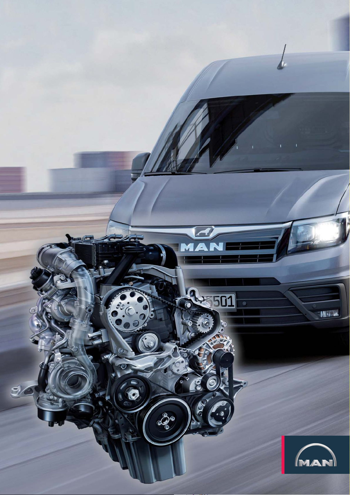
In the MAN TGE, only 2.0-litre turbo diesel engines from the VWnutz modular diesel construction kit are used.
The use of a uniform engine geometry with many identical parts creates high synergy effects and reduces manufacturing and
maintenance costs.
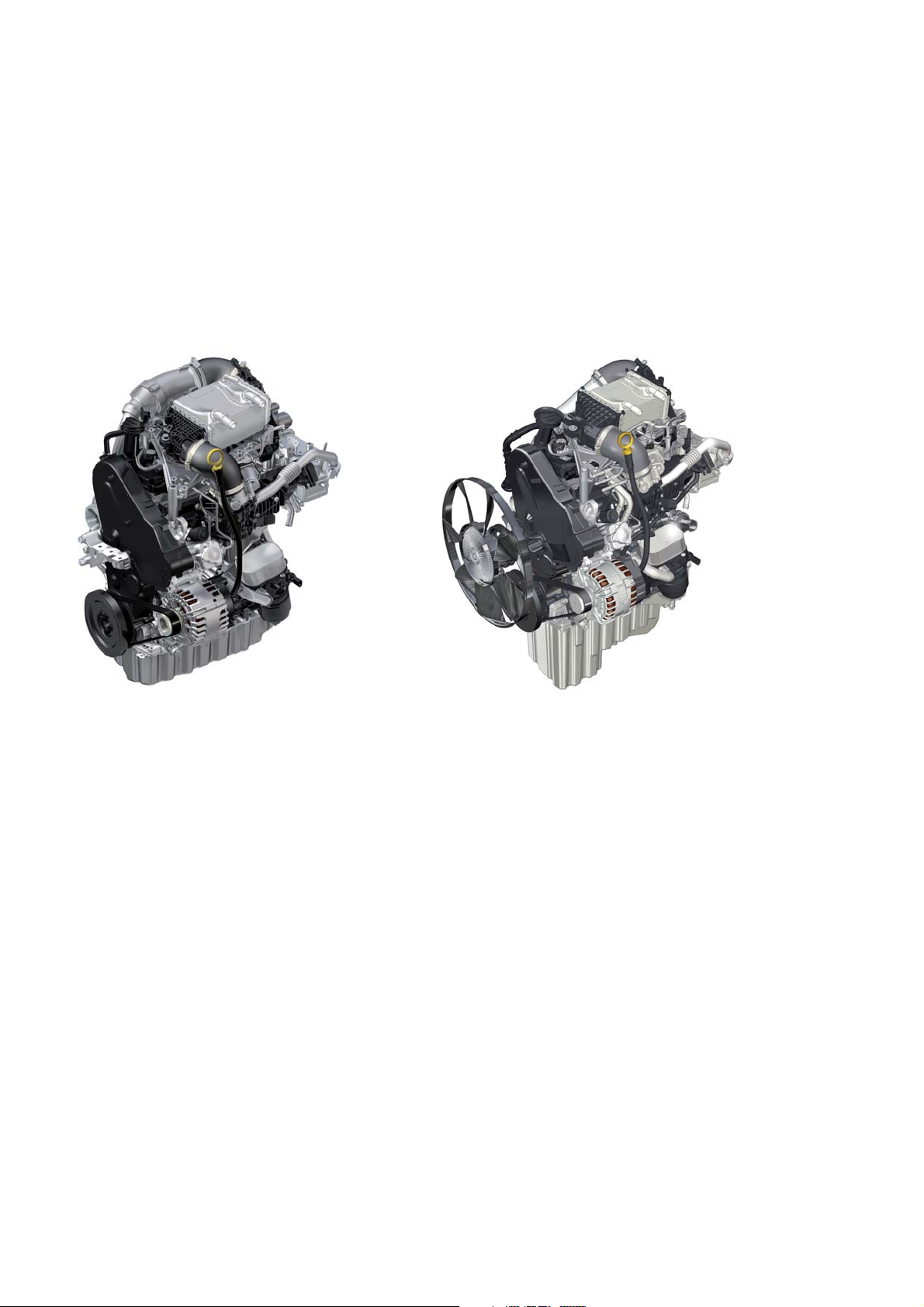
Transverse installation Longitudinal installation
The engines of the MAN TGE have been
specially designed for commercial
vehicles to meet the high requirements
in terms of mileage, driving resistance,
driving profi le and service life. Adjustments were made, for example, to the
intercooling, the cylinder head, the
intake manifold, the EGR cooler, the
turbochargers and the oil pan. The
installation position is adapted to the
commercial vehicle design. Depending
on the drive concept used, the engines
are installed transversely or longitudinally - an absolute special feature within
a vehicle series. In addition, transversely
installed engines are installed at an
angle of 8° to the front in order to make
optimum use of the available installation
space. Longitudinally installed engines
have a larger oil pan and an increased
oil quantity. Engines with one or two
turbochargers are used.
m002_002
A total of up to four power stages are
available, ranging from 75 kW to
130kW. The after-treatment of the
exhaust gases is carried out by an SCR
system for nitrogen oxide reduction.
Additional options, e. g. different
generators and compressors, are
possible with the accessory drive used.
2
Page 3
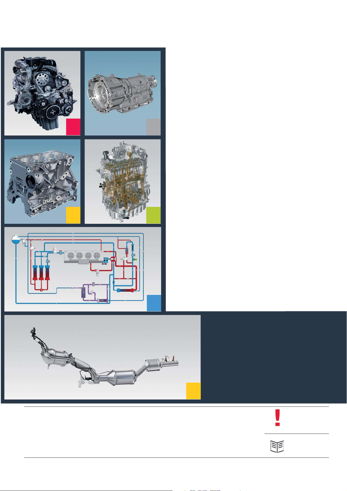
TABLE OF CONTENTS
4 INTRODUCTION
10 GEARBOX
14 ENGINE MECHANICS
4 10
23 OIL SYSTEM
26 COOLING SYSTEM
2314
26
33 ENGINE MANAGEMENT
50 EXHAUST SYSTEM
58 SERVICE
50
The MAN TGE Guide teaches the basics of design and function for sales and after-sales of new vehicle models, new
vehicle components or new technologies.
The MAN TGE Guide is not a sales manual nor a repair guide! Specifi ed values are for the sake of easy understanding
only and refer to the data status valid at the time the MAN TGE Guide was created.
The contents are not updated.
Please use the appropriate technical literature for customer advice, maintenance and repair work.
Hint
Reference
3
Page 4
INTRODUCTION
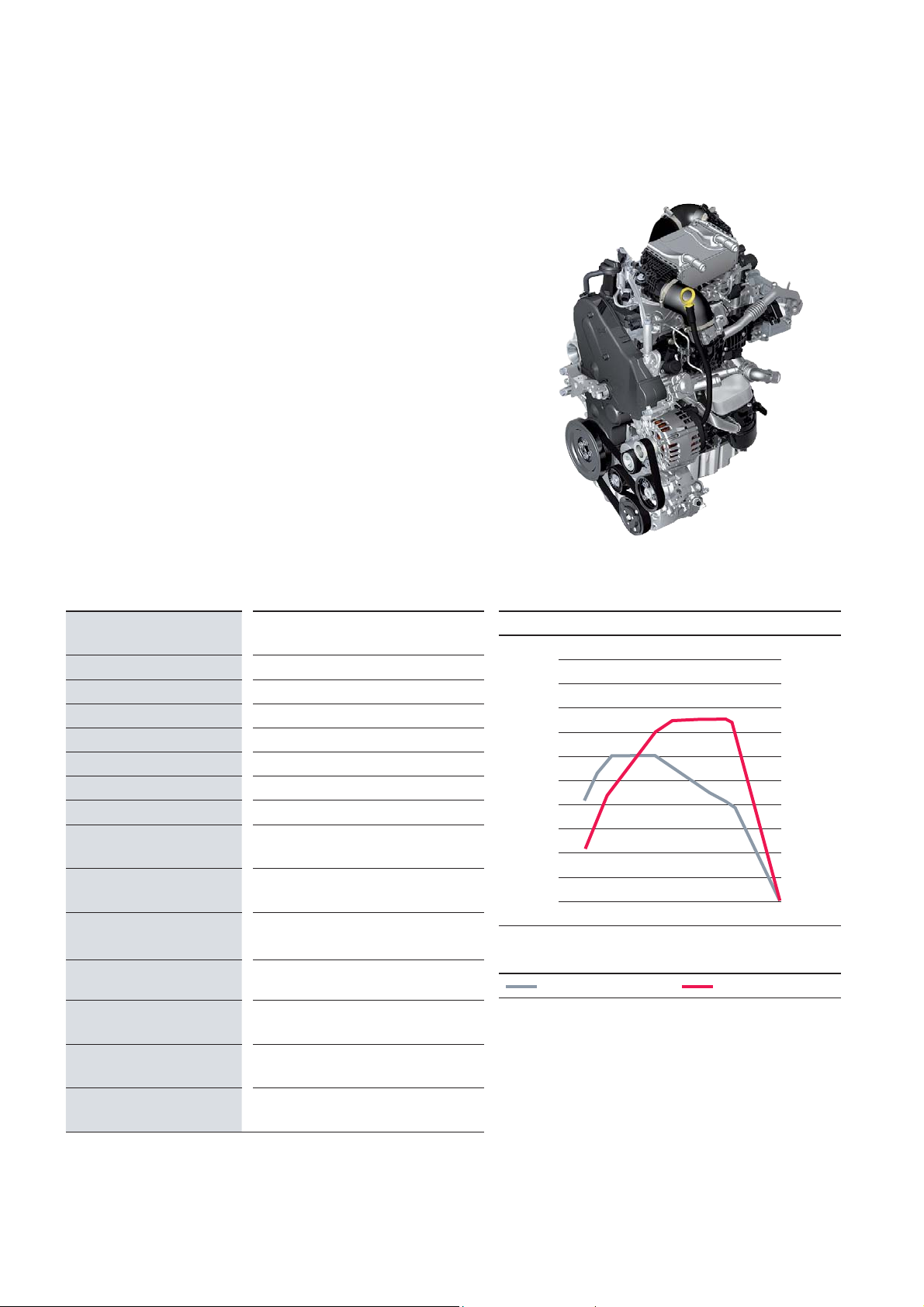
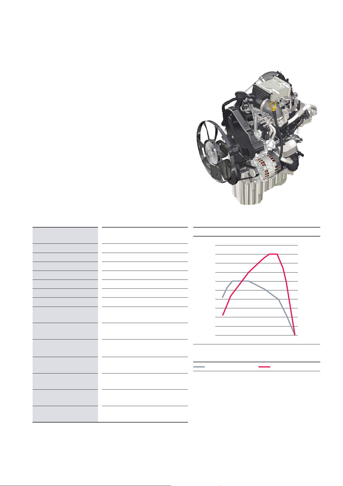
2.0l Turbo diesel - 75 kW - DAUB
Technical features
Transverse installation
Liquid-cooled intercooler
High pressure exhaust gas recirculation
Delphi Common Rail direct injection
Liquid-cooled injector for reduction agent
Injectors with solenoid valve
Single-piston high-pressure pump
(mono turbocharger)
m002_009
Technical data
Engine designation 2.0 l Turbo diesel
75 kW
Engine identifi cation DAUB
Cubic capacity 1968 cm
Engine design 4-cylinder in-line engine
Valves per cylinder 4
Bore 81.0 mm
Stroke 95.5 mm
Compression ratio 15.5: 1
Max. power
at 1/min
Max. torque
at 1/min
Engine management Delphi DCM6.2
Fuel DIN EN 590
Charge Mono turbocharger
3250 – 3500
300 Nm
1400 – 2250
3
75 kW
Torque and power diagram
500 100
400 80
300 60
200 40
Torque [Nm]
100 20
00
1000 2000 3000 4000
Torque [1/min]
Torque Power
Power [kW]
Exhaust gas recirculation yes
Exhaust emission
standard
1)
4
1)
EU6 plus: Light duty homologation <2840 kg reference weight (roller test bench)
EU6 plus
Page 5
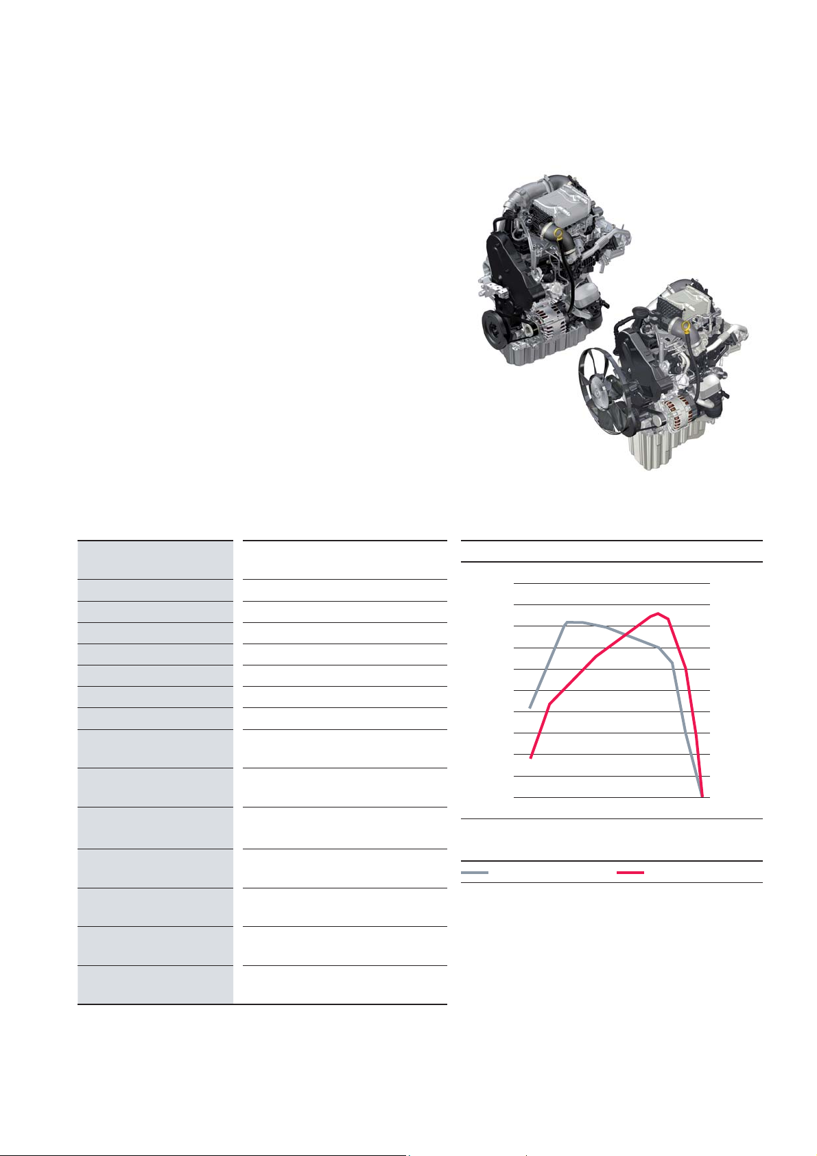
2.0l Turbo diesel - 90 kW - DASA
Technical features
Longitudinal installation
Liquid-cooled intercooler
High pressure exhaust gas recirculation
Delphi Common Rail direct injection
Liquid-cooled injector for reduction agent
Injectors with solenoid valve
Single-piston high-pressure pump
(mono turbocharger)
m002_010
Technical data
Engine designation 2.0 l Turbo diesel
90 kW
Engine identifi cation DASA
Cubic capacity 1968 cm
Engine design 4-cylinder in-line engine
Valves per cylinder 4
Bore 81.0 mm
Stroke 95.5 mm
Compression ratio 15.5: 1
Max. power
at 1/min
Max. torque
at 1/min
Engine management Delphi DCM6.2
Fuel DIN EN 590
Charge Mono turbocharger
3250 – 3500
300 Nm
1400 – 2250
3
90 kW
Torque and power diagram
500 100
400 80
300 60
200 40
Torque [Nm]
100 20
00
1000 2000 3000 4000
Torque [1/min]
Torque Power
Power [kW]
Exhaust gas recirculation yes
Exhaust emission
standard
1)
1)
EURO VI: Heavy duty homologation >2380 kg reference weight (engine test bench)
EURO VI
5
Page 6

2.0l Turbo diesel - 103 kW - DAUA / DASB
Technical features
DAUA - transverse installation
DASB - longitudinal installation
Liquid-cooled intercooler
High pressure exhaust gas recirculation
Delphi Common Rail direct injection
Liquid-cooled injector for reduction agent
Injectors with solenoid valve
Single-piston high-pressure pump
(mono turbocharger)
m002_011
Technical data
Engine designation 2.0 l Turbo diesel
103 kW
Engine identifi cation DAUA / DASB
Cubic capacity 1968 cm
Engine design 4-cylinder in-line engine
Valves per cylinder 4
Bore 81.0 mm
Stroke 95.5 mm
Compression ratio 15.5: 1
Max. power
at 1/min
Max. torque
at 1/min
Engine management Delphi DCM6.2
Fuel DIN EN 590
Charge Mono turbocharger
103 kW
3500 – 3600
340 Nm
1600 – 2250
3
Torque and power diagram
500 125
400 100
300 75
200 50
Torque [Nm]
100 25
00
1000 2000 3000 4000
Torque [1/min]
Torque Power
Power [kW]
Exhaust gas recirculation yes
Exhaust emission
standard
1)
6
1)
EU6 plus: Light duty homologation <2840 kg reference weight (roller test bench)
EU6, EU6 plus
Page 7
2.0l Turbo diesel - 130 kW - DAVA / DAWA
Technical features
DAVA - transverse installation
DAWA - longitudinal installation
Liquid-cooled intercooler
High pressure exhaust gas recirculation
Delphi Common Rail direct injection
Liquid-cooled injector for reduction agent
Injectors with solenoid valve
Double-piston high-pressure pump
(bi-turbocharger)
m002_012
Technical data
Engine designation 2.0 l Turbo diesel
130 kW
Engine identifi cation DAVA / DAWA
Cubic capacity 1968 cm
Engine design 4-cylinder in-line engine
Valves per cylinder 4
Bore 81.0 mm
Stroke 95.5 mm
Compression ratio 15.5: 1
Max. power
at 1/min
Max. torque
at 1/min
Engine management Delphi DCM6.2
Fuel DIN EN 590
Charge Bi-turbocharger
130 kW
410 Nm
1500 – 2000
3
3600
Torque and power diagram
500 150
400 120
300 90
200 60
Torque [Nm]
100 30
00
1000 2000 3000 4000
Torque [1/min]
Torque Power
Power [kW]
Exhaust gas recirculation yes
Exhaust emission
standard
1)
EURO VI: Heavy duty homologation >2380 kg reference weight (engine test bench)
1)
EU6 plus: Light duty homologation <2840 kg reference weight (roller test bench)
EU6, EU6 plus,
EURO V/VI
7
Page 8
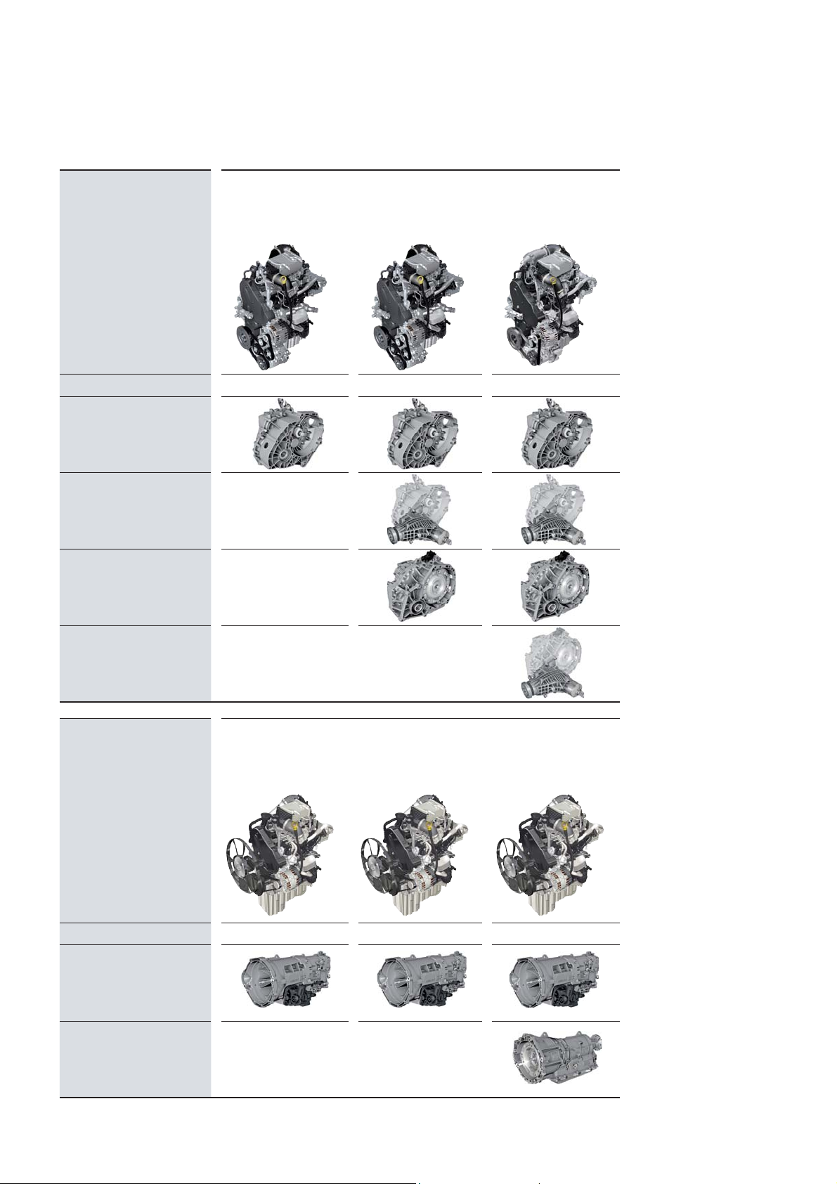
The engine-gearbox combinations
Transverse installation 2.0 l Turbo diesel
75 kW
DAUB
6-speed
manual gearbox
0AX front wheel drive
6-speed
manual gearbox
0AX all-wheel drive
8-speed
automatic gearbox
09Q front wheel drive
2.0 l Turbo diesel
103 kW
DAUA
2.0 l Bi-turbo diesel
130 kW
DAVA
8-speed
automatic gearbox
09Q all-wheel drive
Longitudinal installation 2.0 l Turbo diesel
90 kW
DASA
6-speed
manual gearbox
0F6 rear wheel drive
8-speed
automatic gearbox
0DR rear-wheel drive
2.0 l Turbo diesel
103 kW
DASB
2.0 l Bi-turbo diesel
130 kW
DAWA
8
Page 9

9
Page 10
GEARBOX
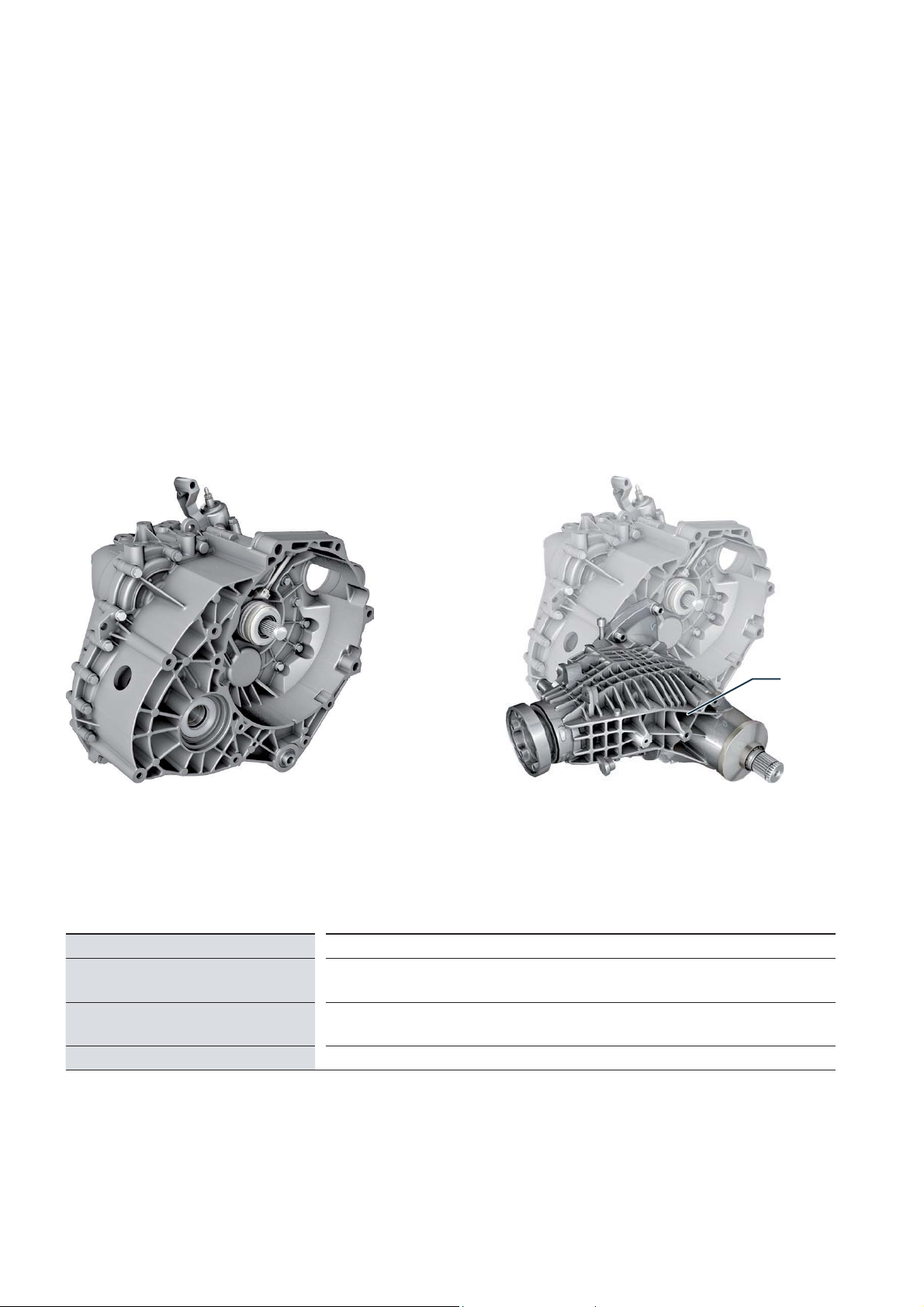
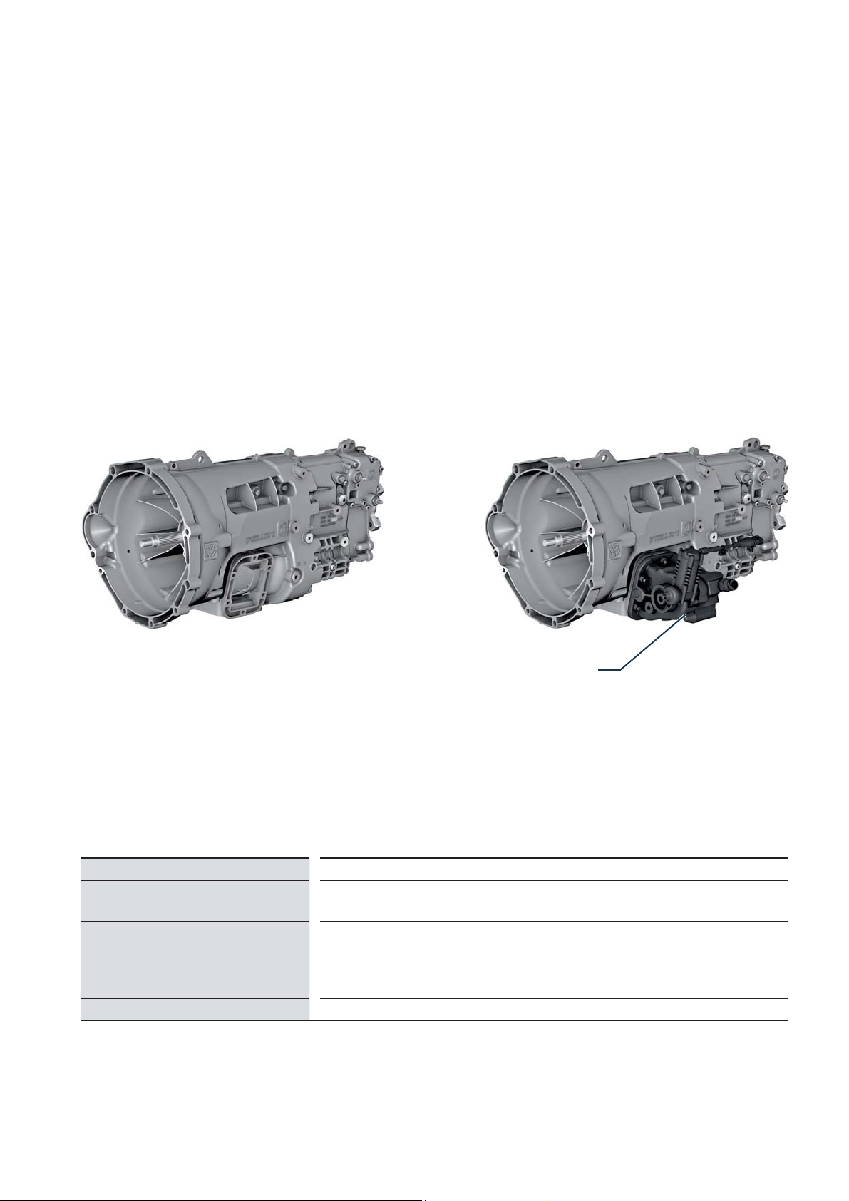
6-speed manual transmission 0AX transverse installation
This transmission is used in front wheel
drive or 4x4 four-wheel drive vehicles.
For use in the MAN TGE, it was
adapted with respect to gear ratios and
to the installation space-specifi c
conditions.
In the MAN TGE, it is used both for
front wheel drive, and with a
fl ange-mounted angle drive
for 4x4 all-wheel drive.
Front-wheel drive All-wheel drive 4x4
Angle drive
Developer/Manufacturer
Gearbox designation
Gearbox characteristics
Torque
m002_080 m002_081
Volkswagen AG
MQ500-6A/-6F
In service code: 0AX
6-speed manual transmission with four shafts and cable control for front-wheel or
all-wheel drive in transverse installation
410 Nm
10
Page 11
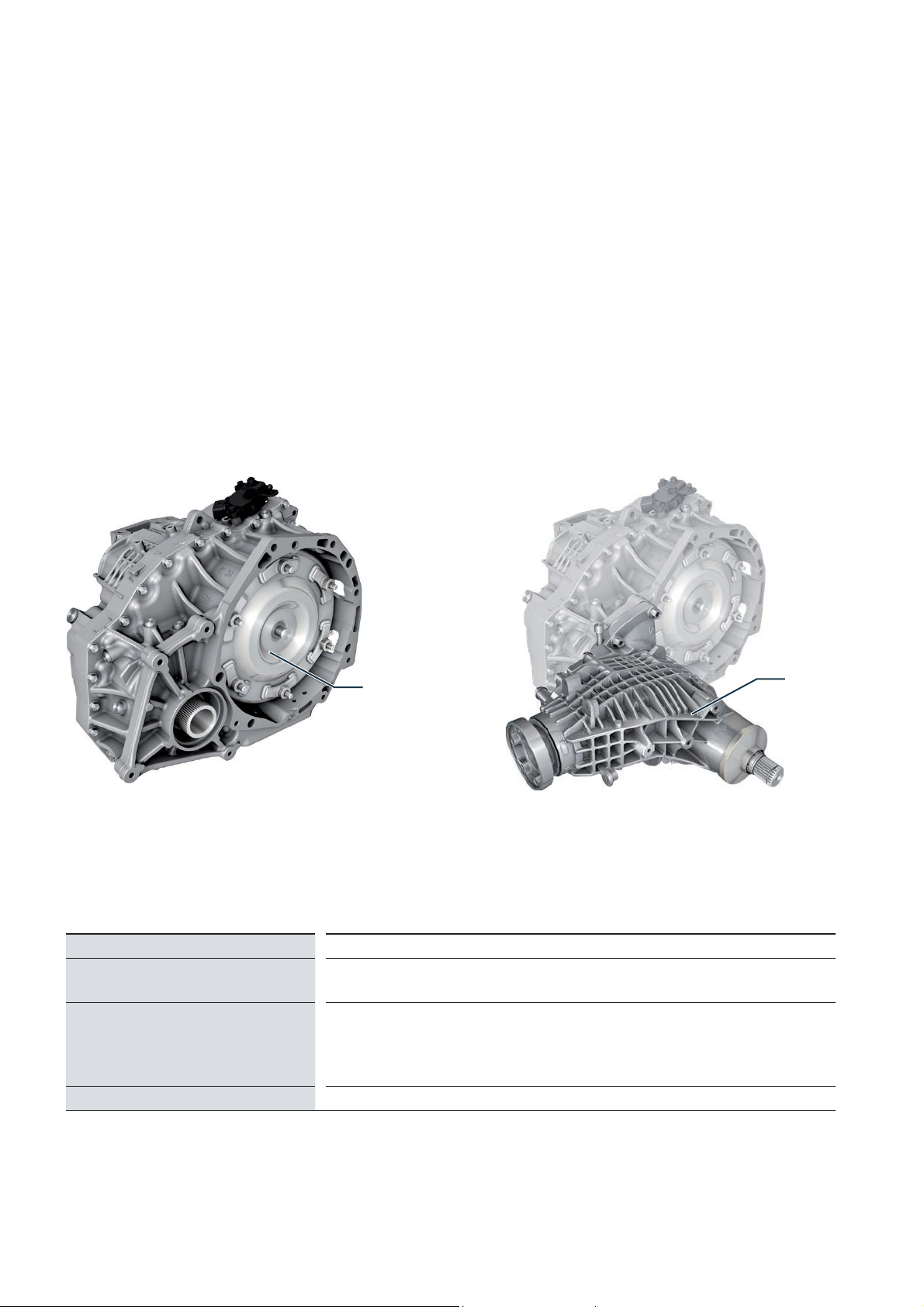
6-speed manual transmission 0F6 longitudinal installation
The newly developed manual transmission is used in rear-wheel drive vehicles.
For the MAN TGE it has been designed
with a correspondingly robust layout.
This applies, for example, to the design
of bearings and synchronization.
A gearbox-side power take-off is available as an option.
Developer/Manufacturer
Gearbox designation
Gearbox characteristics
Torque
m002_082 m002_083
Power take-off
ZF Friedrichshafen AG
ML410-6H
In service code: 0F6
2-shaft manual transmission with single and multiple synchronized speeds.
The gearbox consists of a drive shaft in conjunction with a coaxial output shaft,
a countershaft and a reverse shaft for reverse gear.
The power take-off is driven by the countershaft.
410 Nm
11
Page 12
8-speed automatic transmission 09Q transversal installation
The newly developed automatic transmission is used in front wheel drive or
4x4 four-wheel drive vehicles.
For use in the MAN TGE, care was
taken to ensure a robust design of the
converter, gearbox housing, differential
and parking lock. In all-wheel drive
vehicles, the drive to the rear axle is
provided by a fl ange-mounted angular
drive.
Front-wheel drive All-wheel drive 4x4
Torque converters
Angle drive
Developer/Manufacturer
Gearbox designation
Gearbox characteristics
Torque
m002_078 m002_079
AISIN AW CO., LTD Japan
AQ450-8A/-8F
In service code: 09Q
Electro-hydraulically controlled 8-speed planetary gearbox
(stepped automatic transmission) with hydrodynamic torque converter and slipcontrolled torque converter lock-up clutch for front or all-wheel drive in transverse
installation
410 Nm
12
Page 13
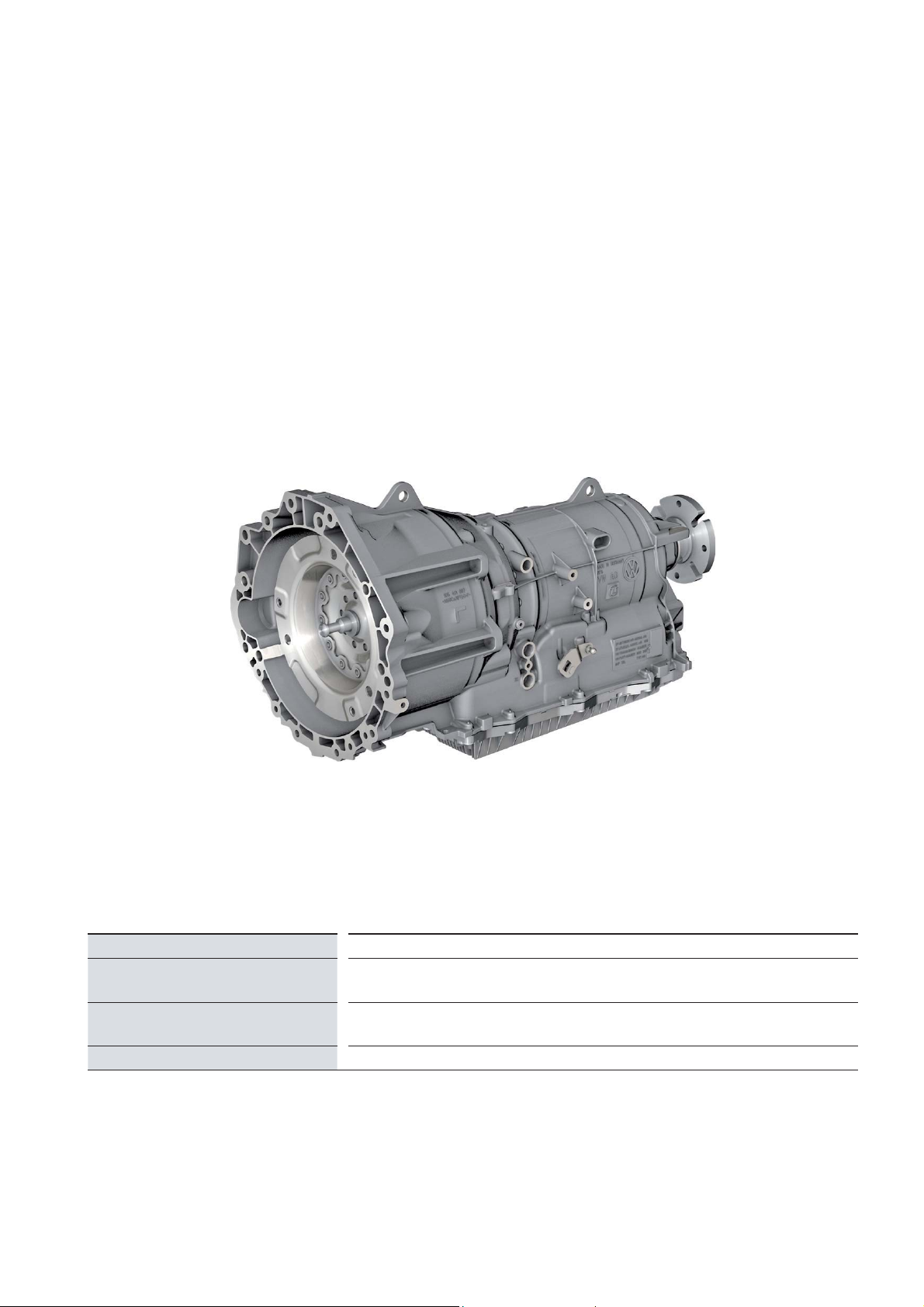
8-speed automatic transmission 0DR longitudinal installation
The newly developed automatic transmission is used in rear-wheel drive
vehicles. For the MAN TGE it has been
designed with a correspondingly robust
layout.
This concerns e. g. the transducer and
the planet set. In addition, the gearbox
housing, lining plates, plate supports
and the parking lock are reinforced.
Developer/Manufacturer
Gearbox designation
Gearbox characteristics
Torque
m002_084
ZF Friedrichshafen AG
AL550-8H
In service code: 0DR
Electro-hydraulically controlled 8-speed planetary gear with hydrodynamic
torque converter with slip-controlled torque converter lock-up clutch
410 Nm
13
Page 14
ENGINE MECHANICS
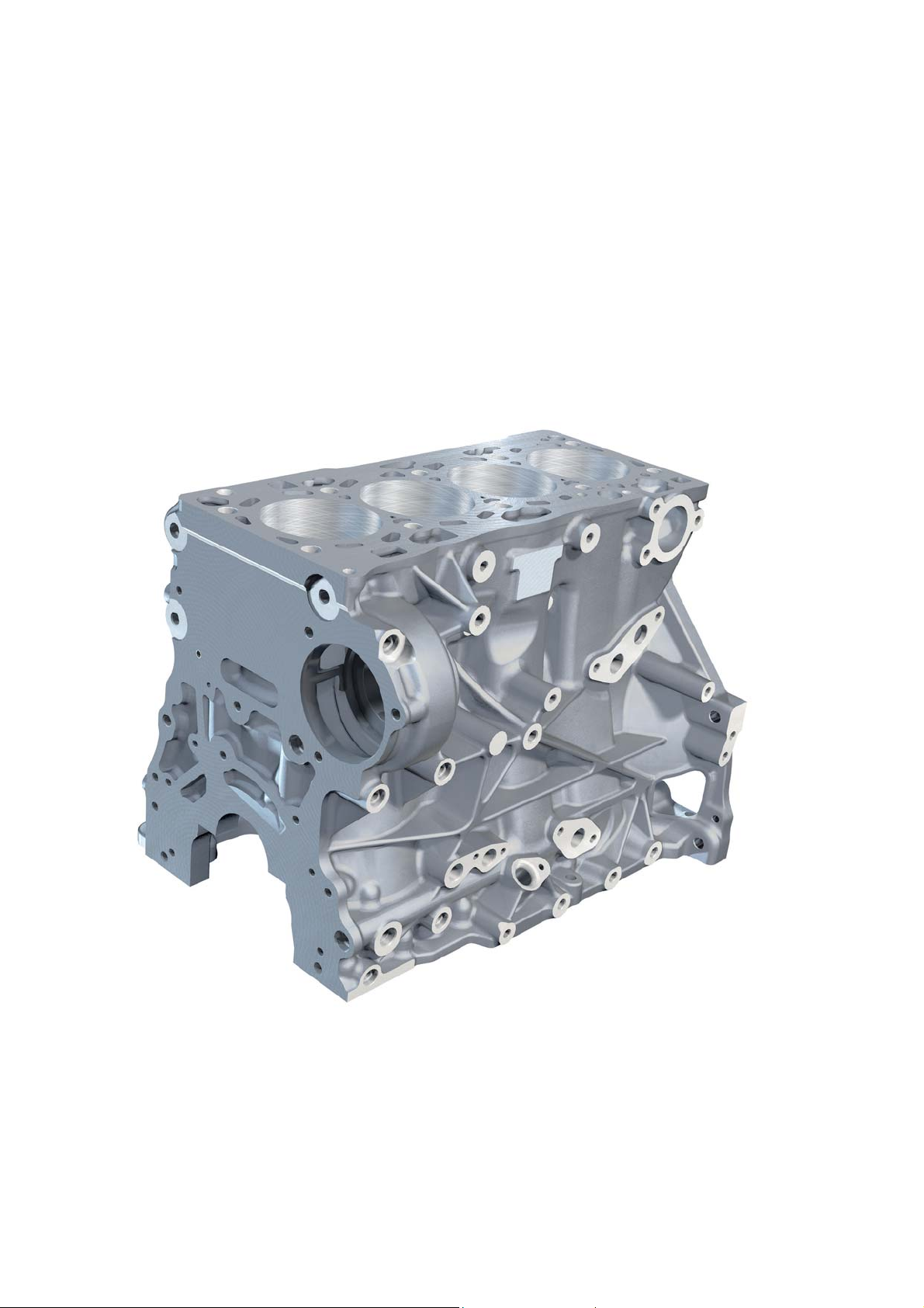
The cylinder block
The cylinder block of the EA288 engine
is made of grey cast iron. This is an alloy
of cast iron with lamellar graphite. The
cylinder block has deep-seated screw
threads for long cylinder head screws.
This achieves a good force fl ow distribution in the structure of the cylinder block
as well as a balanced pressure distribution over the entire circumference of the
cylinder head gasket.
The design of the cooling ducts in the
cylinder block ensures good cooling of
the webs between the cylinders.
14
m002_020
Page 15
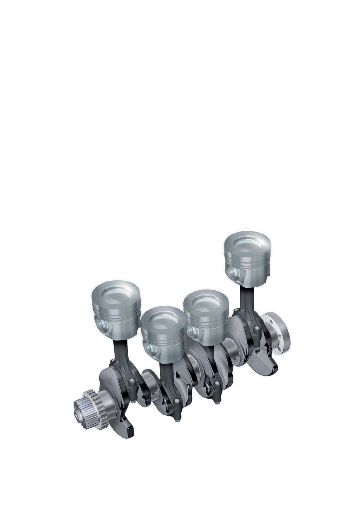
The crank drive
Crankshaft
Due to the high mechanical load, a
forged crankshaft with fi ve bearings is
used in the 2.0l TDI engine. Instead of
the usual eight counterweights, this
Pistons and conrods
The pistons of the EA288 engine have
no valve seat pockets. This design of
the pistons reduces the dead space
and improves the swirl formation of the
crankshaft has four counterweights to
compensate the rotating inertia forces.
This reduces the load on the crankshaft
intake air in the cylinder. The pistons
have an annular cooling channel into
which oil is injected via piston nozzles
bearings. The toothed belt wheel for
driving the oil pump is shrunk on the
crankshaft.
for cooling the piston ring zone. The
connecting rods are designed as
cracked tapered connecting rods.
m002_021
15
Page 16
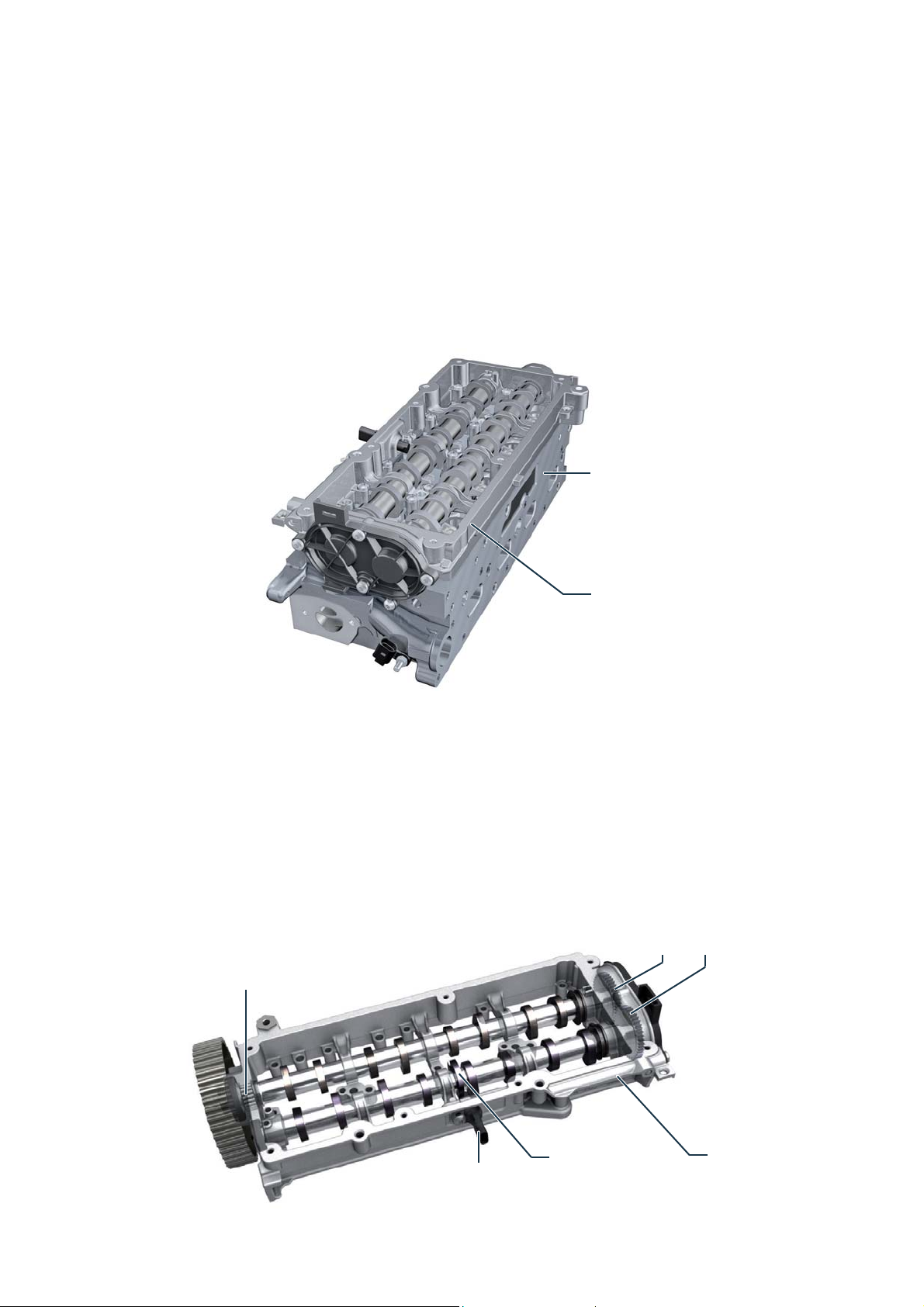
The cylinder head
The cylinder head is made of an aluminium alloy.
Four valves are installed per cylinder.
The valve arrangement is the classic
design, i. e. the inlet valves are located
on the inlet side and the outlet valves on
the outlet side. The valve is actuated by
roller cam followers with compensating
elements.
The combustion chamber pressure
transmitter for cylinder 3 G679 is integrated in the glow plug for this cylinder
and screwed into the cylinder head like
the other glow plugs. In order to
increase service life, the head of the
EA288Nutz has been improved in terms
of thermal management compared to
the basic engine.
Cylinder head
Camshaft housing
Camshaft housing
The camshafts are fi rmly and inseparably integrated into a closed bearing
frame by means of a thermal joining
process. This process enables a very
rigid design of the camshaft bearings
with low weight. In order to reduce
friction, the fi rst bearing, most loaded by
Needle roller bearing
m002_022
the toothed belt drive, is a needle roller
bearing. The encoder wheel for Hall
sensor G40 ins located on the inlet
camshaft. The signal from the Hall
sensor enables the engine control unit
to detect the current position of the
camshafts.
Both camshafts are driven by only one
drive wheel.
The intake camshaft is driven by a spur
gearing from the exhaust camshaft.
This design improves the service life of
the timing belt.
Spur gearing
16
Hall sensor G40
Encoder wheel
m002_023
Bearing frame with
cam shafts
Page 17
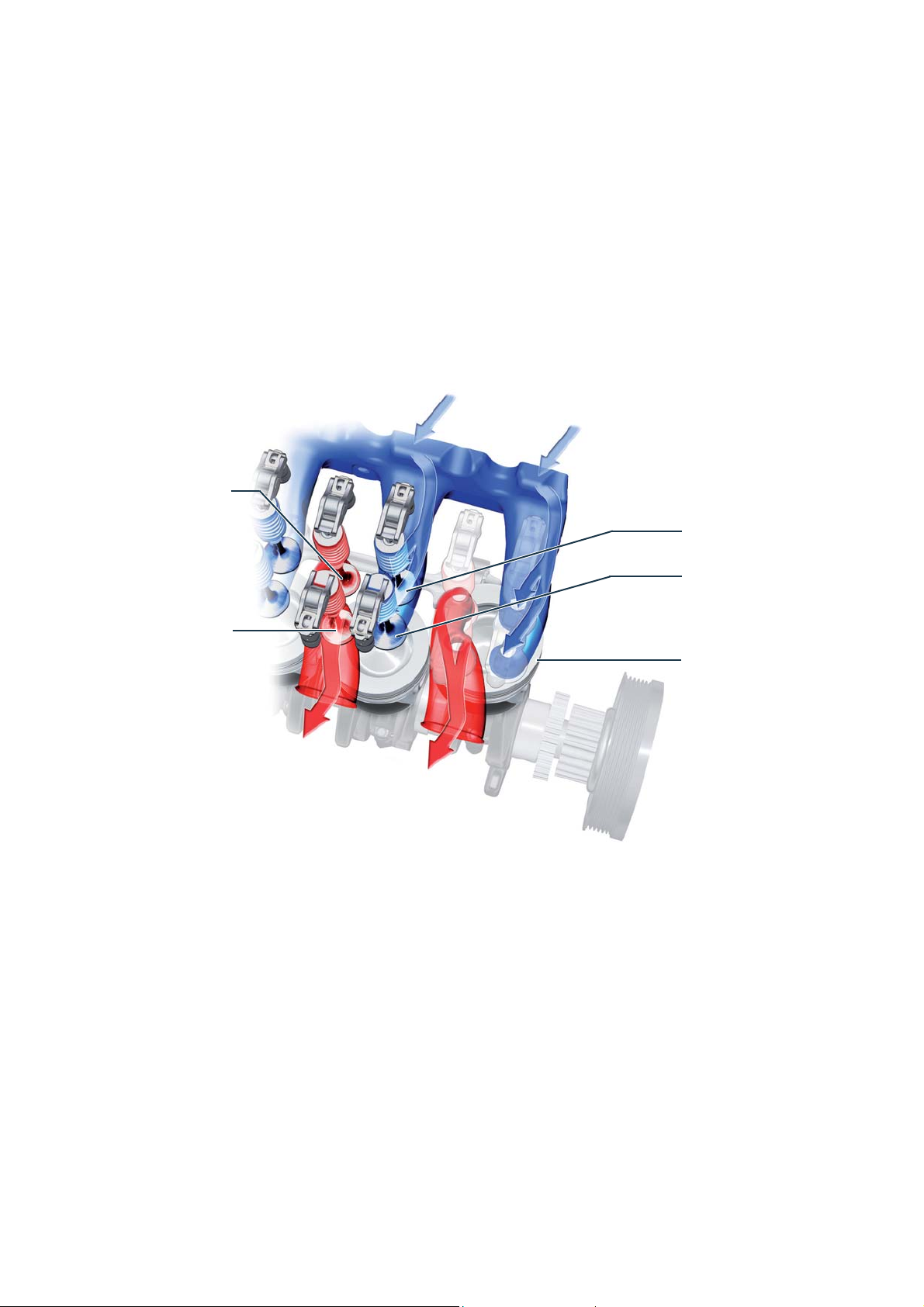
Valve arrangement
In order to meet future exhaust emission
standards, the valve arrangement is
rotated with respect to the longitudinal
axis of the engine. As a result, the inlet
and outlet channels for each cylinder
First exhaust valve
Cylinder 2
Second outlet valve
Cylinder 2
are arranged one after the other in fl ow
direction.
The camshafts thus operate one intake
and one exhaust valve per cylinder. The
Intake air
valve arrangement is designed in a way
that the inlet and outlet ducts achieve a
maximum fl ow rate with good swirl
effect.
First inlet valve
Cylinder 2
Second inlet valve
Cylinder 2
Cylinder 1
Exhaust gas
m002_028
17
Page 18
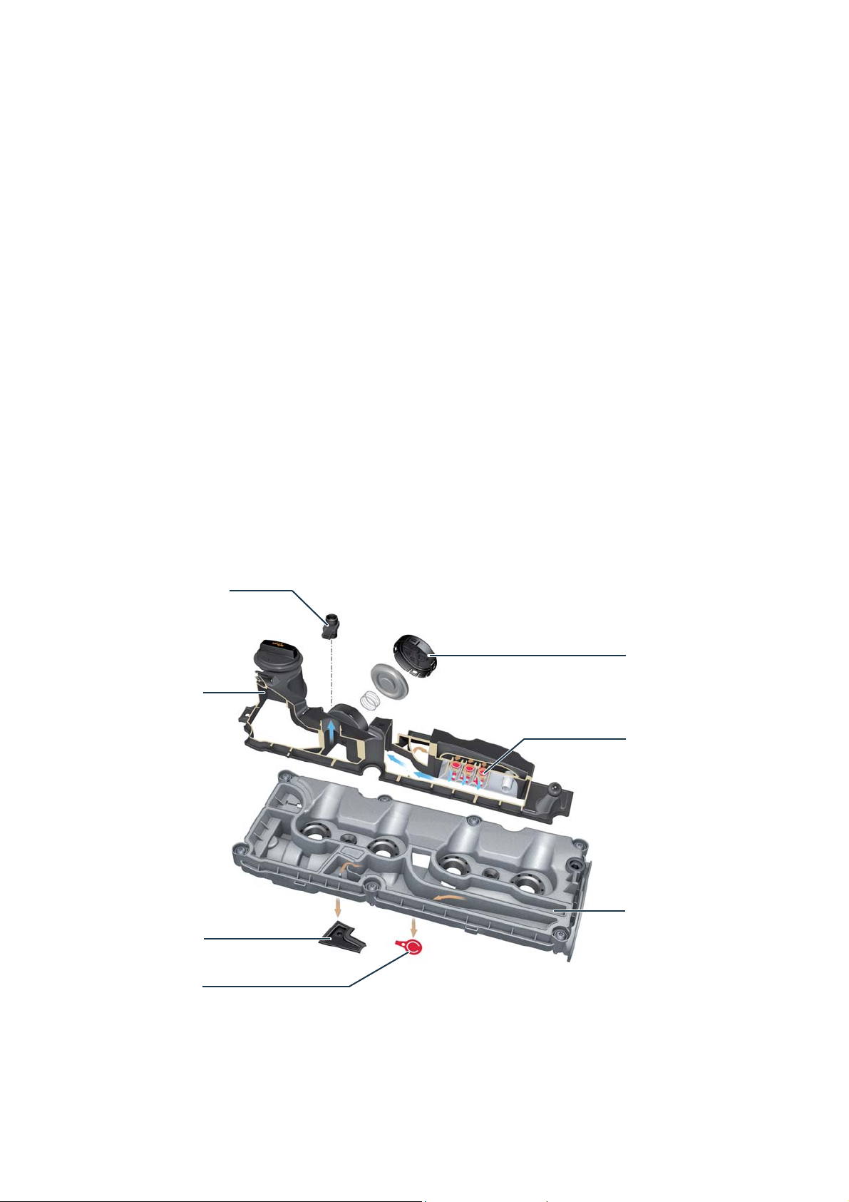
The crankcase ventilation
The components of the crankcase
ventilation system are integrated into the
cylinder head cover, in addition to the oil
fi ller neck and the pressure accumulator
for the engine's vacuum system. The air
currents occurring in combustion
engines between piston rings and
cylinder walls, the so-called blow-by
gases, are returned to the intake area
For countries with a cold climate, the crankcase ventilation is equipped with a heating resistor. The heating resistor prevents
freezing of the line connection from the cylinder head cover to the intake manifold in case of low outside temperatures.
Heating resistor for
crankcase ventilation
via the crankcase ventilation. This
avoids environmental pollution caused
by oil-containing gases. For effective oil
separation, crankcase ventilation is
performed in several stages. First of all,
the blow-by gases from the crankshaft
and camshaft space are transferred to a
calming volume of the cylinder head
cover.
There, the larger oil droplets settle on
the walls and drip into the cylinder head.
Subsequently, the oil-containing gases
are separated off by a cyclone separator.
The purifi ed gases are fed to the suction
pipe via the pressure control valve and
are then lead to the combustion.
Vacuum tank
Oil return from
fi ne oil separator
Gravity valve
for oil return fl ow
Pressure regulator
Fine oil separation
(cyclones)
Calming volume
m002_024
18
Page 19

The toothed belt drive
The components of the control drive are
driven by a toothed belt from the crankshaft. Starting from the crankshaft, the
toothed belt runs to the tension pulley,
via the camshaft drive wheel to the drive
wheel of the high-pressure pump of the
common-rail injection system and the
drive wheel of the coolant pump. The
return pulleys ensure a bigger wrap
angle of the toothed wheels by the
toothed belt. The toothed belt was
reinforced due to the increased loads.
Camshaft drive wheel
Return pulley
High pressure pump
drive wheel
Tension pulley
Coolant pump drive wheel
Return pulley
Toothed belt wheel of crankshaft
The toothed belt is stretched four times per
crankshaft revolution due to the actuation of a
double-piston high-pressure pump.
In order to keep the load on the timing belt low, a
bi-oval toothed belt wheel is installed on the
crankshaft. The bi-oval toothed belt wheel
changes the transmission ratio and thus counteracts the stretching of the toothed belt.
Crankshaft toothed belt wheel
m002_025
Large diameter
Small diameter
m002_026
19
Page 20

Oil and vacuum pump drive
The oil pump and the vacuum pump are
integrated in one housing. The pump
housing is screwed to the underside of
the cylinder block. The pumps have a
common drive shaft and are driven by a
toothed belt from the crankshaft. The
maintenance-free toothed belt runs
directly in the oil and is only tensioned
by the centre distance of the toothed
belt wheels.
Drive via crankshaft
Cylinder block Oil pump
20
m002_027
Vacuum pump
Page 21

Drive of auxiliary units
In order to meet the diverse customer
requirements, an auxiliary unit drive is
used which can be expanded on a
modular basis. In addition to the usual
units, such as generator and air-conditioning compressor, it is also possible to
drive an auxiliary air-conditioning compressor or an additional generator.
This allows to provide the required
energy for vehicles with superstructures,
such as camper vans or refrigerated
boxes, e. g. for air conditioning, cooling,
or for the drive of electrically operated
auxiliary units.
Basic drive AC drive
Generator
(different power
levels)
For a engine with generator, an elastic
belt is used exclusively as V-ribbed belt.
For all other variants, the V-ribbed belt is
tensioned with a belt tensioner.
Generator
(different power
levels)
Auxiliary drive
m002_085 m002_086
Generator
(different power
levels)
AC compressor
Additional generator
(in 180-Aversion)
AC compressor
Generator
(different power
levels)
AC compressor
Auxiliary air conditioning compressor
m002_087 m002_088
21
Page 22

QUESTIONNAIRE
Which answer is correct?
One or more answers of the given ones can be correct.
1. How many counterweights does the crankshaft of the EA288Nutz have?
a) 4
b) 6
c) 8
2. Where does the control unit get the camshaft position signal from?
a) Inductive encoder on the camshaft sprocket
b) Hall sensor at the outlet camshaft
c) Hall sensor at the inlet camshaft
3. Which components are integrated in the crankcase ventilation?
a) Inlet valve, drain valve, positioner
b) Cyclone separator, pressure regulator, gravity valve
c) Glow pin, oil spray nozzle, pressure limiter
4. How many valve pockets do the pistons of the EA288 engine have?
a) 4
b) There are none.
c) 2
5. Which statement about the camshaft housing is correct?
a) The camshaft housing is inseparably integrated into the cylinder head.
b) The camshafts can be replaced individually.
c) The camshafts are inseparably integrated into a closed bearing frame.
d) The camshafts can only be replaced completely with the bearing frame.
22
Solutions: 1) a, 2) c, 3) b, 4) b, 5) c
Page 23

OIL SYSTEM
The oil supply
The oil pressure generated by the
engine oil pump is used to adjust the
camshaft. The oil pump can adjust its
delivery volume in two pressure stages
to the operating conditions of the
engine. In addition, it is driven by the
Oil pressure switch
F1
crankshaft via a maintenance-free
toothed belt. It supplies crank drive,
valve train, high-pressure and lowpressure exhaust turbochargers with
suffi cient engine oil.
The piston accumulator ensures that
there is suffi cient oil volume in the low oil
pressure stage for fast adjustment of
the vane adjuster even during engine
operation.
Oil pressure switch
for reduced oil pressure F378
Oil pressure control
The oil pressure is controlled via two pressure stages.
The change from the low pressure stage with a small
fl ow rate at 2.0-2.3 bar to the high pressure stage with
a large fl ow rate at 3.3-3.8 bar takes place at a speed
of 3000 rpm.
Hint
In order to improve the running-in behaviour of the new engine, the oil pump has been switched to the high oil
pressure stage for the fi rst 1000 km. After the installation of new parts such as engine, engine section, cylinder
head, camshaft housing and exhaust turbocharger, the oil pressure control must be adjusted to the high oil pressure
level for 1,000 km.
The high oil pressure level must be set with the vehicle diagnostic tester.
m002_029
High pressure level
3,3-3,8 bar
Low pressure level
2,0-2,3 bar
Pressure requirement
m002_030
3000 l/min
23
Page 24

Construction of the oil and vacuum pump
Flutter valves
Housing cover
Housing
Drive wheel with
housing cover
Oil pump
The oil pump is a volume-fl ow-controlled vane pump in which the delivery
characteristics of the pump can be
changed by means of an eccentrically
Vane pump
mounted adjusting ring.
The position of the rotating adjustment
ring changes the delivery volume of the
Vacuum pump
Regulating piston
Check valve
m002_031
pump, thus adapting the pump's drive
power to the operating conditions of the
engine.
Vacuum pump
The vacuum pump draws in air from the
brake booster and the engine's vacuum
system via vacuum lines and transfers it
to the cylinder block via the fl utter
24
valves. The extracted air then passes as
blow-by gas through the crankcase
ventilation into the intake manifold and
is fed to the combustion chamber. The
oil used to lubricate the vacuum pump
is fed into the oil pan via the fl utter
valves from the working chamber of the
vacuum pump.
Page 25

25
Page 26

COOLING SYSTEM
The thermal management
The cooling system of the EA288 engine
is controlled by a thermal management
system. The thermal management
serves for the optimum distribution of
the available engine heat, taking into
account the heat and cooling requirements of the interior, engine and transmission.
1
2 3 4
4
5
The thermal management quickly heats
up the engine in the warm-up phase
after a cold start. The heat fl ows generated in the engine are directed to the
components of the cooling system in a
targeted and demand-oriented manner.
The rapid heating of the coolant and the
optimal use of the available heat in the
cooling system mainly reduces internal
engine friction, which contributes to the
reduction of fuel consumption and
exhaust emissions.
In addition, a comfortable air conditioning of the passenger compartment is
achieved.
16 17
76
4
15
18
3
20
Legend
1
2 2/3-way venting valve
3
4
5 2/3-way valve
6
26
Coolant compensation tank
(thermostatically controlled)
Throttle
Check valve
(thermostatically controlled)
Shut-off valve for coolant of heating
system N279
7
8
9
10
11
12 2/3-way valve
Coolant pump for high-temperature circuit
V467
Cooler for exhaust gas recirculation
Pre-cooler for exhaust gas recirculation
Coolant pump
Coolant thermostat
(thermostatically controlled)
Page 27

4
8 4
10
19
22
4
21
23
11 12
4
25
9
4
13
3
14
3
13
14
15
16
17
18
19
24
Pump for exhaust gas recirculation cooler
V400
Temperature sensor
Coolant circulation pump V50
Heat exchanger
Rear heat exchanger
Auxiliary water heating
Engine oil cooler
26
m002_032
20
21
22
23
24
25
26
Coolant regulator
Intercooler
Intercooling pump V188
Reduction agent injection valve N474
Radiator for low-temperature circuit
Check valve
Main radiator
27
Page 28

High-temperature circuit
When the engine is cold, the
coolant circulates from the coolant
pump (10) via the oil cooler (19), the
cylinder head, the cylinder block and
the heat exchanger (16). The 2/3-way
bleed valve (6) is open. It closes at a
coolant temperature of 49 °C. When the
engine has reached operating temperature, the coolant thermostat (11) opens
1
3 4
4
2
5
4
15
at 92 °C. The coolant pump for hightemperature circuit V467 (7) is controlled
depending on the heating requirement
and the coolant temperature. The
heating requirement is sensed via the
control unit of the air conditioning
system. The control is performed by the
engine control unit. The pump for the
exhaust gas recirculation cooler V400
6
7
(13) is controlled by the engine control
unit via a PWM signal with a fl ow rate of
70% after the ignition is switched on. It
runs permanently over all operating
areas. In case of higher EGR cooling
requirements, the control is increased to
100% fl ow rate.
4
4
9
8
10
12
11
3
13
14
16 172018
Legend
1
Coolant compensation tank
2 2/3-way venting valve
(thermostatically controlled)
3
4
5
Throttle
Check valve
2/3-way valve
(thermostatically controlled)
6 Shut-off valve for coolant of heating
system N279
19
25
4
26
m002_034
7 Coolant pump for high-temperature circuit
V467
8
9
10
11
Cooler for exhaust gas recirculation
Pre-cooler for exhaust gas recirculation
Coolant pump
Coolant thermostat
12 2/3-way valve
(thermostatically controlled)
28
Page 29

Low-temperature circuit
The liquid-cooled intercooling enables a
regulation of the air temperature in the
intake manifold to a set point that meets
the requirements. The intercooling
temperature is controlled by the engine
control unit via the activation of the
1
2
intercooling pump V188 (22). The
reference variable for the control is the
intake manifold temperature after the
intercooler. The intercooling coolant
circuit is connected to the engine
cooling circuit for the purpose of fi lling
and venting via a check valve (4) and a
throttle (3). There is no connection to
the engine cooling circuit during operation. The reduction agent injection valve
N474 (23) is integrated in the lowtemperature circuit.
13 Pump for exhaust gas recirculation cooler
V400
14
15
16
17
18
19
Temperature sensor
Coolant circulation pump V50
Heat exchanger
Rear heat exchanger
Auxiliary water heating
Engine oil cooler
Hint
Observe the repair guide when refi lling the coolant.
3 4
22
21
23
24
m002_033
20
21
22
23
24
25
26
Coolant regulator
Intercooler
Intercooling pump V188
Reduction agent injection valve N474
Radiator for low-temperature circuit
Check valve
Main radiator
29
Page 30

Coolant regulator
The coolant regulator is a 3/2-way valve, operated via a wax element. Depending on the coolant temperature, the coolant
regulator switches between the large and the small cooling circuit. This allows the engine to reach its operating temperature
more quickly.
Warm-up phase
During the engine's warm-up phase, the coolant fl ow
from the cylinder block to the main water cooler is
blocked by the large disc of the coolant regulator. The
coolant fl ows directly into the small cooling circuit via
the coolant pump. Due to with the stagnant coolant –
with the coolant pump switched off – the engine
reaches its operating temperature faster. When the
coolant pump is switched on, it is ensured that a
suffi cient amount of coolant fl ows through the cylinder
head and exhaust gas recirculation cooler during the
engine's warm-up phase.
Operating temperature
Coolant from
cylinder block
Connection to
coolant pump
Coolant regulator
Connection to
main radiator
m002_035
Coolant from
cylinder block
At a coolant temperature of about 92 °C, the large disc
of the coolant controller starts to open and thus integrates the main radiator into the large cooling circuit.
At the same time, the small disc of the coolant regulator blocks the direct path to the coolant pump.
Connection to
coolant pump
Coolant regulator
Connection to
main radiator
m002_036
30
Page 31

Coolant temperature sensor G62
The coolant temperature sensor is screwed into the cylinder head near the combustion chamber.
This arrangement enables the engine control unit to determine the engine temperature, independent of the coolant fl ow rates which depend on the operating point.
Signal use
The engine control unit requires the coolant temperature sensor signal as a correction value for
calculating the injection amount, the boost pressure and the exhaust gas recirculation amount.
Thesignal is also used to switch the switchable coolant pump on and off.
Effects of signal loss
If the signal fails, the engine control unit calculates a fi xed replacement value. The switchable
coolant pump remains permanently switched on.
Electronically controlled coolant pumps
Coolant pump for high-temperature circuit V467
The coolant pump for high-temperature circuit is an electronically controlled centrifugal pump with
brushless drive. It draws the coolant from the heat exchanger and delivers it to the combustion
engine. For this purpose, the pump is controlled with a PWM signal as required
by the engine control unit.
Coolant circulation pump V50
The pump for coolant circulation is an electronically controlled centrifugal pump with brushless
drive. It draws in the coolant from the heat exchanger via a check valve and delivers it to the
auxiliary water heating. For this purpose, the pump is controlled with a PWM signal as required by
the engine control unit.
Intercooling pump V188
The intercooling pump is an electronically controlled
centrifugal pump with brushless drive. It draws the
coolant from the intercooler cooling circuit and
conveys it to the intercooler. For this purpose, the
pump is controlled with a PWM signal as required by
the engine control unit.
m002_037
31
Page 32

32
Page 33

ENGINE MANAGEMENT
Injection system
The TGE uses a common rail injection
system made by the company Delphi. It
provides a maximum injection pressure
of 2000 bar.
The 2.0 litre TDI engine 130 kW with
bi-turbo unit is fi tted with a doublepiston high-pressure pump. The rail also
differs in volume and weight.
Injection system with
single-piston high-pressure pump
Since the return lines of the injectors are
connected to the fuel supply, there is a
pressure of 4-6 bar.
Injection system with
double-piston high-pressure pump
m002_038
In addition to the design of the high-pressure pump, the systems differ in the design of the high-pressure accumulator (fuel rail),
in the number of high-pressure pipes and in the size of the bore of the injection nozzles used.
Hint
When replacing the injectors, make sure that you use the injectors specifi ed for the performance variant in MANTIS
(MAN Parts Information System). The different injection nozzles differ only in the bore diameter and can be distinguished externally only by the part number.
33
Page 34

Injection system with single-piston
high-pressure pump
Single-piston high-pressure pump
The high-pressure pump is driven by the
toothed belt drive.
The pressure piston is actuated by a ram
mounted in a roller.
The fuel metering valve N290 is integrated
in the high-pressure pump. The compressed fuel is transferred at a pressure of
up to 2000 bar via a high-pressure pipe to
the high-pressure storage tank.
The maximum pump capacity is 0.42 cm
Drive shaft
3
/r.
Quantity metering valve
Pump head
Pressure piston
High-pressure connection
Fuel fl ow
Fuel return
m002_039
Pump casing
High-pressure accumulator
The high-pressure reservoir has a volume of
12.3 cm
high-pressure pump via a high-pressure line
and slightly shorter than the high-pressure
reservoir of the double-piston high-pressure
pump. The control valve for fuel pressure
N276 and the fuel pressure sensor G247
are screwed into the high-pressure reservoir.
3
. It is connected to the
Control valve for fuel pressure
N276
High-pressure connections
to the injectors
Return
High-pressure accumulator
High pressure connection to
the single-piston high-pressure
pump
Fuel pressure sensor
G247
m002_040
34
Page 35

Overview
7
6
10
4
5
9
2
3
1
9
9
9
8
m002_041
Legend
1
2
3
4
5
6
7
8
9
10
Fuel pump
Fuel tank
Fuel fi lter
Single-piston high-pressure pump
Fuel temperature sensor G81
Fuel pressure sensor G247
High-pressure accumulator (rail)
Control valve for fuel pressure N276
Injection valves N30, N31, N32, N33
Valve for fuel metering N290
Special features
High pressure pump with single piston and one high pressure output
One high-pressure fuel line between pump and high-pressure accumulator
High pressure accumulator with one high-pressure connection
8-hole injector nozzles with 700 ml
High fuel pressure up to 2000 bar
Fuel supply pressure 4.0-6.0 bar
Fuel return pressure from the
injection valves 4.0-6.0 bar
Fuel return pressure 0-0.3 bar
35
Page 36

Injection system with double-piston
high-pressure pump
Double-piston high-pressure pump
This high-pressure pump is also operated
by the toothed belt drive. In contrast to the
single-piston high-pressure pump, the
pressure pistons are actuated by a slider.
The fuel metering valve N290 is integrated
in the high-pressure pump. The compressed fuel is transferred at a pressure of
up to 2000 bar via a high-pressure pipe to
the high-pressure storage tank.
The maximum pump capacity is 0.7 cm
3
/r.
Drive shaft
Pump casing
Pump head
Pressure piston
Quantity metering valve
High-pressure connection
Fuel fl ow
Fuel return
High-pressure connection
m002_042
High-pressure accumulator
The high-pressure accumulator has a
volume of 18 cm
high-pressure pump
via two high-pressure lines and slightly
longer than the
high-pressure accumulator of the singlepiston high-pressure pump. Here too, the
control valve for fuel pressure N276 and the
fuel pressure sensor G247 are screwed into
the high-pressure reservoir.
3
. It is connected to the
Control valve for fuel pressure
N276
High-pressure connections
to the injectors
Return
High-pressure accumulator
High pressure connection to
the
single-piston high-pressure
pump
Fuel pressure sensor
G247
m002_043
36
Page 37

Overview
7
6
10
4
5
9
2
3
1
9
9
9
8
m002_044
Legend
1
2
3
4
5
6
7
8
9
10
Fuel pump
Fuel tank
Fuel fi lter
Double-piston high-pressure pump
Fuel temperature sensor G81
Fuel pressure sensor G247
High-pressure accumulator (rail)
Control valve for fuel pressure N276
Injection valves N30, N31, N32, N33
Valve for fuel metering N290
Special features
Double-piston high-pressure pump with two high-pressure outputs
Two high-pressure fuel lines between pump and high-pressure accumulator
High pressure accumulator with two high-pressure connections
8-hole injectors with 900 ml
High fuel pressure up to 2000 bar
Fuel supply pressure 4.0-6.0 bar
Fuel return pressure from the
injection valves 4.0-6.0 bar
Fuel return pressure 0-0.3 bar
37
Page 38

The injectors
In the two fuel systems, the only difference between the injectors is the bore diameter
of the injection channels. Structure and functionality are identical.
Structure and functionality
A data carrier is located on the head side of the injection valves. A 20-digit correction value for the injection
valves is embossed on this data carrier. The correction
value is determined on a test bench during the production for each injection valve.
It describes the injection behaviour of this unique
injector.
The injectors are fi xed by clamping claws in the
cylinder head. The have the task to inject the correct
amount of fuel into the combustion chambers at the
right time. For this, they are controlled by the engine
control unit.
If the solenoid valve is not actuated, the pressure ratios
at the nozzle needle and in the control chamber are
the same. The injection nozzle remains closed. If the
solenoid valve is actuated, the switching valve opens
the fuel return fl ow and the pressure in the control
chamber is reduced. Now the injection starts. In order
to stop the injection process, the solenoid coil is not
actuated. The switching valve closes the return fl ow,
the pressure in the control chamber rises and the
nozzle needle spring closes the nozzle needle.
Connection to the
high pressure accumulator (rail)
Connection to the
fuel return
Electrical connection
Switching valve spring
Solenoid
Switching valve
Nozzle needle
spring
Nozzle needle
m002_045
38
Page 39

Actuation phases
Characteristic diagram of the actuation phases
The engine control unit requires the input of
the correction value from the head side of the injection
valve in order to individually control the actuation
of this injection valve in the entire map range and to
correct it over the entire correction range. This enables
a precise control of the injection quantities. This helps
to reduce fuel consumption and exhaust emissions as
well as to smoothen the engine operation.
One of the main measurement variables are the signals
from the two knock sensors.
Valve closed and
nozzle needle closed
m002_047
Valve opened and
nozzle needle closed
[A]
Valve opened and
nozzle needle opened
m002_048 m002_049
Control current
m002_046
[μs]
m002_050 m002_051 m002_052
The solenoid valve is actuated.
The control current increases to about
23 A at a voltage of 12 V.
The injection valve remains closed in
this phase.
The switching valve lifts out of its seat.
The control current is regulated to the
holding current of about 9 A.
In this phase, the nozzle needle also
begins to lift.
The nozzle needle is open and the
injection takes place. The injection
quantity is determined by the duration of
the actuation.
39
Page 40

QUESTIONNAIRE
Which answer is correct?
One or more answers of the given ones can be correct.
1. What is the maximum injection pressure for EA288Nutz engine?
a) 1800 bar
b) 2500 bar
c) 2000 bar
2. At what temperature does the coolant regulator start to open?
a) 92 °C
b) 85 °C
c) 87 °C
3. How many pressure stages does the oil pressure control have?
a) 1
b) 2
c) 3
4. What is the fuel pre-pressure for the common rail system?
a) 3-4 bar
b) 4-6 bar
c) 1-2 bar
5. Which is the pressure in the return line of the injector?
a) 0-0.3 bar
b) 4-6 bar
c) 1-2 bar
40
Solutions: 1) c, 2) a, 3) b, 4) b, 5) b
Page 41

The pre-heating system
The 2.0-litre TDI engine with commonrail injection system has a diesel quickstart pre-heating system.
This system allows the diesel engine to
start immediately under all climatic
conditions.
Long pre-heating times are no longer
necessary and the starting process is
comparable to that of a gasoline engine.
Advantages of the pre-heating system
Engine start comparable to that of a gasoline engine at temperatures down to -24 °C
Extremely short heating-up time. The glow plug reaches temperatures of up to 1000 °C in 2 seconds.
Controllable temperatures for pre- and afterglow.
Self-diagnosis capability.
Component of the Euro on-board diagnostic pre-heating system
System overview
Engine speed sensor
G28
Coolant temperature sensor
G62
On-board control unit
J519
Engine control unit
J623
Control unit for automatic glowing time
J179
Diagnostic interface
for data bus J533
Control unit in panel
insert J285
Indicator lamp for
pre-heating time K29
Glow plug 1 Q10
Glow plug 2 Q11
Glow plug 3 Q12
Glow plug 4 Q13
m002_053
41
Page 42

Function
Preheating
The steel glow plugs are controlled in a
phase-shifted way by the engine control
unit via the control unit for automatic
glowing time J179, using a pulse width
modulated signal (PWM). The voltage at
Afterglow
For afterglow, the switch-on time of the
on-board power supply voltage in the
PWM duty cycle is set in such a way
that an effective voltage of 4.4 V results.
Afterglow is carried out up to a coolant
the individual glow plug is set via the
duty cycle of the PWM pulses.
A maximum voltage of 11.5 V is available for a quick start at an outdoor
temperature of less than 24 °C. This
temperature of 24 °C after starting the
engine and for a maximum of 5 minutes.
Afterglow helps to reduce hydrocarbon
emissions and combustion noise during
the warm-up phase. In vehicles with a
ensures that the glow plug heats up to
over 1000 °C within a very short time
(max. 2 seconds). This reduces the
preheating time for starting the engine.
start-stop system, the afterglow process
is not interrupted when the engine stop
function is active. This avoids frequent
temperature changes and thus protects
the material of the steel glow plug.
Phase-shifted control of the glow plugs
In order to relieve the on-board power
supply voltage during the glow phases,
the glow plugs are controlled in a
phase-shifted way. The falling signal
edge always controls the next glow
plug.
Glow plug
Cylinder 1
Cylinder 2
Cylinder 3
Cylinder 4
Time (s)
m002_054
42
Page 43

Cylinder pressure controlled combustion control
In order to achieve a precise fuel injection control, the engine management
takes into account the pressure curve in
the cylinder during combustion.
The engine control unit receives information about the actual pressure curve
in the cylinder from the combustion
chamber pressure transmitter for cylinder 3 G679.
This sensor is integrated in the housing
of the glow plug on cylinder 3.
The cylinder pressure controlled combustion control system is capable of
adjusting the injection timing and thus
the combustion pressure profi le to the
different exhaust gas recirculation rates,
fuel qualities and component tolerances
over the lifetime of the engine. A software model in the engine control unit
calculates the pressure curve for each
cylinder from the signal from the combustion chamber pressure sensor for
cylinder 3 G679 and the signal from the
engine speed sensor G28. Correction
values for the injection time and the
actuation time of the injection valve are
determined in accordance with the
deviations from the nominal/actual
comparison.
Advantages of cylinder pressure guided combustion control
Precise control of injection timing and injection quantities
Adjustment of injection quantity tolerances of the injectors over the running time
Stable and smooth engine running over all cylinders
Adjustment of the injection in case of ignition delay due to high exhaust gas recirculation rates and different fuel qualities
Control of challenging engine operating modes and mode changes, e. g. regeneration of the NOx storage catalyst or
regeneration of the diesel particulate fi lter, without infl uencing the driving characteristics.
Function
The measuring principle of the combustion chamber pressure transmitter for cylinder 3 G679 is based on a heating rod which
moves in axial direction and transfers the combustion pressure in the cylinder to a measuring diaphragm. This measuring
diaphragm is equipped with strain gauges that change their electrical resistance in case of deformation. An integrated electronic
evaluation system calculates an analog voltage signal from the resistance value – in relation to the measured cylinder pressure –
and transmits it to the engine control unit.
43
Page 44

Construction of glow plug 3 Q12 with combustion chamber pressure
transmitter for cylinder 3 G679
Electrical plug-in connection
Sensor plus
Sensor ground
Sensor signal
Electronic evaluation system
Glow plug plus
Diaphragm
Strain gauges
Axially movable heating element
Bellows
(sealing to combustion chamber)
Filament
Combustion pressure
m002_055
Signal use
The signal from the combustion chamber pressure sensor for cylinder 3 G679 is used by the engine control unit for calculating
the correction value for the fuel injection control.
Effects of signal loss
If the signal fails, there is no cylinder pressure controlled combustion control. This can lead to uneven engine running.
44
Page 45

The exhaust turbochargers
Mono turbocharger
The turbocharger is integrated in an
exhaust manifold module.
The turbocharger has adjustable guide
vanes that can infl uence the exhaust
gas fl ow to the turbine wheel. This has
the advantage that an optimum boost
pressure can be achieved over the
entire speed range of the engine. The
guide vanes are adjusted via a linkage
by negative pressure. The vacuum is
controlled by an electro-pneumatic
Vacuum actuator for guide vane adjustment
Vacuum connection
Turbocharger compressor
valve, the valve for boost pressure
limitation. The position sensor for the
boost pressure regulator G581 is integrated in the vacuum actuator of the
turbocharger. This position sensor is a
displacement sensor that enables the
engine control unit to determine the
position of the blades of the turbocharger. The EA288-TDI engine with
EU6 emissions standard has a lowpressure exhaust gas recirculation
system. Here, the exhaust gas is only
taken after the diesel particulate fi lter
and led to the compressor wheel of the
turbocharger. The entire exhaust gas
mass fl ow is thus maintained in front of
the turbocharger's turbine wheel. This
leads to a better response of the turbocharger; thus, higher boost pressures
and thus larger cylinder fi llings are
possible especially in partial load operation.
Operating lever for
guide vane adjustment
Exhaust gas turbine with
guide vane adjustment
Intake air from the air fi lter
Pulsation damper Connection of low pressure exhaust gas recirculation
The pulsation silencer arranged in the direction of fl ow to the intercooler reduces interfering noise in the charge air path.
Exhaust manifold
m002_056
Air control system
The higher demands on exhaust aftertreatment to be expected in future
require an extended control and regulation structure for the engine's air
system. The engine management
system of the EA288 diesel engine is
supported by the engine's air control
system. The air control system is based
on a model that calculates the conditions of the air system in all engine
operating states. All pressure values,
temperature values and mass fl ows are
determined in the intake air, charge air
and exhaust gas section of the engine.
These parameters are used for regulat-
ing the boost pressure, the cylinder
fi lling and the exhaust gas recirculation
rate. The advantage of this model is that
the engine's complex air control system
manages with a limited number of
sensors, despite a large number of
actuators.
45
Page 46

Bi-turbocharger
In the 2.0-litre TDI engines with 130 kW,
two turbochargers connected in series
generate the boost pressure, which
together form a bi-turbocharger unit.
Pressure box for
steering vane adjustment
High-pressure exhaust turbocharger
with adjustable guide vanes
Exhaust manifold
The intake air is pre-compressed at low
engine speeds by the low-pressure
exhaust turbocharger and is fi nally
compressed by the high-pressure
exhaust turbocharger
(two-stage operation). At high engine
speeds, only the low-pressure exhaust
turbocharger compresses the intake air
(single-stage operation).
Compressor bypass valve
Low pressure exhaust
turbocharger
Pressure box for wastegate valve
Pressure box for exhaust gas fl ap
m002_058
Special features of the exhaust turbocharger system with
bi-turbocharger unit
High pressure exhaust turbocharger with adjustable vanes with small turbine wheel and small compressor wheel.
This arrangement results in fast response at low engine speeds.
Low-pressure exhaust turbocharger with large turbine wheel and large compressor wheel. This arrangement results in high
boost pressure at high engine speeds. Consequently, high engine power is achieved at high engine speeds.
Compact construction: High- and low-pressure exhaust turbochargers are installed directly at the exhaust manifold.
46
Page 47

Air control system
In the 2.0-litre TDI bi-turbo engine, two
turbochargers connected in series
generate the boost pressure. The intake
air is pre-compressed at low engine
9
8
1
2
6
10
12
13
7
speeds by the low-pressure exhaust
turbocharger and is fi nally compressed
by the high-pressure exhaust turbocharger (two-stage operation). At high
11
14
15
5
18
engine speeds, only the low-pressure
exhaust turbocharger compresses the
intake air (single-stage operation).
16
17
19
Legend
1
2
3
4
5
6
7
8
9
10
11
12
13
20
4
3
Air fi lter
Airfl ow meter G70
Low pressure turbocharger compressor wheel
Booster pressure sensor 2 G447
Compressor wheel of the high pressure
exhaust turbocharger
Compressor bypass valve
Throttle valve control unit GX3
Booster pressure sensor G31
Intake air temperature sensor G42
Intercooler
Charge air temperature sensor after
intercooler G811
Actuator for exhaust gas recirculation GX5
Cooler for exhaust gas recirculation
23
21
22
24
m002_059
14
15
Exhaust gas temperature sensor 1 G235
Turbine bypass fl ap
16 Pressure box for exhaust gas fl ap with
position sensor 2 for boost pressure regulator
G580
17
18
Valve for turbine switching N529
Turbine wheel of the high-pressure exhaust turbocharger
19
Solenoid valve for boost pressure limitation N75
20 Pressure box for guide vane adjustment with
position sensor for boost pressure regulator G581
21
22
23
Wastegate valve
Pressure box for wastegate valve
Solenoid valve 2 for boost pressure limitation N274
24 Turbine wheel of the low-pressure exhaust turbo-
charger
47
Page 48

Exhaust gas recirculation module
The low-pressure exhaust gas recirculation module consists of the exhaust gas recirculation cooler and the actuator 2 for
exhaust gas recirculation V339. It is located between the diesel particulate fi lter and the compressor side of the turbocharger.
Due to the engine-close arrangement and the compact design, the fl ow losses in the exhaust gas return section are reduced to
a minimum.
Actuator 2 for exhaust gas recirculation V339
Exhaust gas pipe with cooling function for
cooler with longitudinally installed engine
48
Exhaust gas pipe without cooling function for
cooler with transversely installed engine
m002_065
Cooler for exhaust gas recirculation
Page 49

Cooler for exhaust gas recirculation
All recirculated exhaust gases are passed through the exhaust gas recirculation cooler. Due to the fact that the exhaust gases
are colder, a larger amount of exhaust gases can be supplied to the intake air. In addition, the components in the charge air
section are protected from excessively high exhaust gas temperatures.
Filter element
The low-pressure exhaust gas recirculation module consists of the exhaust gas recirculation cooler and the actuator 2 for
exhaust gas recirculation V339. It is located between the diesel particulate fi lter and the compressor side of the turbocharger.
Due to the engine-close arrangement and the compact design, the fl ow losses in the exhaust gas return section are reduced to
a minimum.
Actuator 2 for exhaust gas recirculation V339
The actuator 2 for the exhaust gas
recirculation V339 is controlled by the
engine control unit with a PWM signal
and actuates the throttle valve of the
exhaust gas recirculation system. The
position of the throttle valve, in conjunction with the position of the exhaust fl ap
in the exhaust fl ap control unit, adjusts
the pressure gradient from the exhaust
tract to the intake passage. The amount
of recirculated exhaust gases is regulated by the pressure gradient.
The higher the pressure gradient, the
greater the volume of recirculated
exhaust gases. Since a high pressure
drop occurs at high engine load, the
exhaust gas recirculation rate in this
operating state is controlled by the
actuator for exhaust gas recirculation.
The exhaust gas fl ap remains open for
this.
Effects of failure
If the actuator 2 for exhaust gas recirculation V339 fails, the throttle valve of the exhaust gas recirculation system is closed by a
spring. There is no exhaust gas recirculation.
Potentiometer 2 for exhaust gas recirculation G466
The potentiometer 2 for exhaust gas
recirculation G466 is integrated in the
actuator 2 for exhaust gas recirculation
V339. The signal determines the position of the actuator 2 for exhaust gas
recirculation V339. With this information
the engine control unit calculates and
controls the recirculated exhaust gas
volume.
Effects of failure
If the signal of potentiometer 2 for exhaust gas recirculation G466 fails, the exhaust gas recirculation is deactivated. The actuator
2 for exhaust gas recirculation V339 is no longer activated by the engine control unit and the throttle valve of the exhaust gas
recirculation system is closed by a spring.
49
Page 50

EXHAUST SYSTEM
The design of the exhaust gas aftertreatment system is identical for all
power levels of the
2.0l TDI engine in the MAN TGE. The
oxidation catalyst follows the respective
turbocharger system. With a corrugated
pipe as transition, the diesel particulate
fi lter with SCR blocking catalyst follows
as a module. The injection valve for
reduction agent N474 is installed into
this module. In addition to the exhaust
gas temperature sensors (G235, G448,
G495, G648) and the NO
(G687), a new sensor for detecting the
soot particle emission is installed downstream the SCR blocking catalyst
(particle sensor G784). The injection
valve for reduction agent is supplied
with reduction agent (AdBlue
reduction agent tank via the reduction
sensor
x
®
) from the
agent supply unit (GX19). The reduction
agent tank has a capacity of about 18
litres. The range is about 5200 km. In
addition to a level sensor, the feed
pump and the heating system, a quality
sensor is installed in the feed module to
monitor the quality of the reduction
agent (quality sensor for reduction agent
G849).
Exhaust gas aftertreatment
For vehicles with SCR system (exhaust gas standard EU6), the front exhaust pipe contains a lambda sensor, three temperature
sensors, the reduction agent injection valve and the corresponding catalysts.
Lambda sensor
Temperature sensor 2
Reduction agent
injection valve N474
Oxidation catalyst
Temperature sensor 3
Diesel particulate fi lter
with SCR coating
Blocking catalyst
Particle mass sensor
NO
sensor
x
m002_066
50
Page 51

Reduction agent injection valve N474
Location and task
The reduction agent injection valve N474 is installed
upstream of the module consisting of a diesel particulate fi lter and SCR blocking catalyst. It is integrated
into the low-temperature coolant circuit of the thermal
management system and has the task of introducing
the reduction agent into the exhaust gas stream in
metered quantities downstream of the oxidation
catalyst.
Location and task
Reduction agent
injection valve N474
m002_067
The reduction agent injection valve N474 is installed
upstream of the module consisting of a diesel particulate fi lter and SCR blocking catalyst. It is integrated
into the low-temperature coolant circuit of the thermal
management system and has the task of introducing
the reduction agent into the exhaust gas stream in
metered quantities downstream of the oxidation
catalyst.
Electrical
connection
Solenoid valve
Connection of reduction agent line
Cooling connections
m002_068
Effects of failure
In the event of a defective injection valve, only insuffi cient, too much or no reduction agent can be injected into the exhaust
system. The exhaust gas values can no longer be maintained. Depending on the type of fault, the exhaust gas warning light K83
(MIL) and the AdBlue
®
warning indicator which indicates a fault in the SCR system are switched on in the panel insert display.
51
Page 52

Reduction agent tank
In addition to the fuel tank with a capacity of about 75 litres, there is a tank with
a capacity of about 18 litres of reduction
agent (AdBlue
The consumption of reduction agent
depends on the individual driving style,
the operating temperature of the system
and the ambient temperature.
The reduction agent tank is fi lled via the
fi ller neck for reduction agent underneath the fuel fi ller neck and is closed
by a blue tank cap. The reduction agent
tank is located on the underbody in
front of the fuel tank. In order to be able
to absorb the reduction agent fl owing in
at a high fl ow rate, a compensation
volume has been integrated in the upper
part of the venting system.
®
).
m002_069
Fuel fi ller neck Reduction agent fi ller neck
Assembly
Control unit for
reduction agent heating
J891
Venting membrane
Venting pipe Filler neck
Compensating volume
Filling pipe
Reduction agent tank
52
Conveying unit for
reduction agent dosing system GX19
m002_070
Page 53
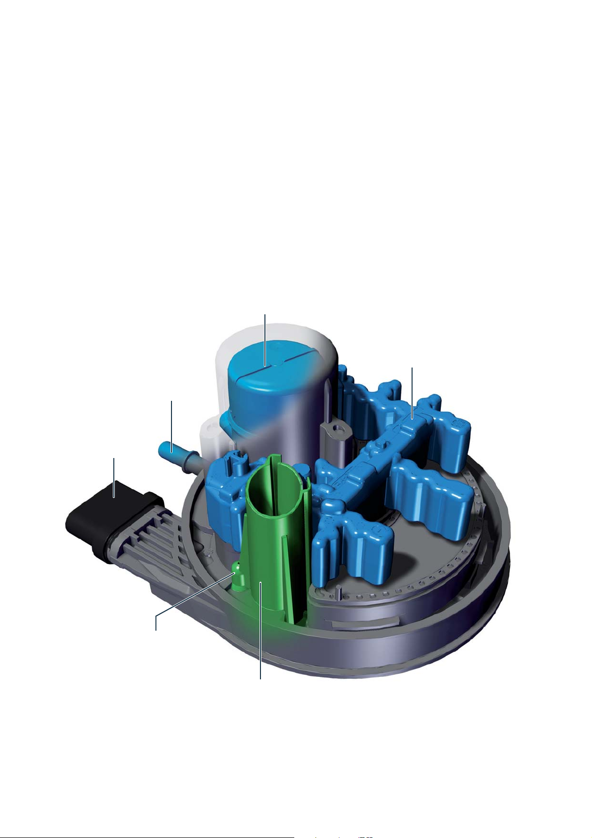
The conveying unit for the reduction agent
dosing system
Location and task
The following components are integrated in the conveying unit for reduction agent dosing system GX19:
Pump for reduction agent V437
Tank sensor for reduction agent G684
Heating for reduction agent tank Z102
Temperature sensor for reduction agent G685
Reduction agent quality sensor G849
Pump for reduction agent V437
Heating for
reduction agent tank Z102
Connection for
reduction agent line
Electrical connection
Temperature sensor for
reduction agent G685
Tank sensor for reduction agent G684
m002_071
53
Page 54

AdBlue® warning indicators for
reduction agent tank
Level warning stage 1
The fi rst prompt to refi ll reduction agent is displayed
when a range of 2400 km can be reached with the
remaining AdBlue
The engine control unit calculates the remaining range
based on the current amount of reduction agent in the
tank and the consumption of reduction agent.
Level warning stage 2
The warning increases when there is less of 1000 km
of remaining range. For this purpose, the warning is
displayed in yellow, supplemented by a warning triangle. The vehicle can only be driven for the displayed
remaining range. If no reduction agent is refi lled in
suffi cient quantity, the engine can no longer be started
after the remaining range has elapsed and the engine
has been switched off.
®
.
m002_072
Level warning stage 3
If there is no more AdBlue® in the reduction agent tank,
the warning symbol is displayed in red. Reduction
agent must be refi lled in order to be able to start the
engine again.
m002_073
m002_074
54
Page 55

QUESTIONNAIRE
Which answer is correct?
One or more answers of the given ones can be correct.
1. What temperature do the glow plugs reach within 2 seconds?
a) 1000 °C
b) 650 °C
c) 800 °C
®
2. What happens if the level of the reduction agent (AdBlue
a) Creep mode
b) Power reduction
c) No engine start possible
3. Which cylinder is used to measure the combustion chamber pressure?
a) 1st cylinder
b) 3rd cylinder
c) 4th cylinder
) is displayed as empty?
4. How is the mono turbocharger regulated?
a) by means of guide vane adjustment
b) by means of the wastegate valve
c) there is no regulation
5. What is the combustion chamber pressure sensor required for?
a) better cold start behaviour
b) combustion control
c) check of mechanical faults
6. How are the glow plugs activated?
a) approximately 12 V are applied at cold start
b) approximately 6 V are applied at cold start in order to relieve the battery
c) they are controlled with a PWM signal
Solutions: 1) a, 2) c, 3) b, 4) a, 5) b, 6) c
55
Page 56

System overview
Sensors
Engine speed sensor G28
Hall sensor G40
Airfl ow meter G70
Coolant temperature sensor G62
and coolant temperature sensor 3 G812
Coolant temperature sensor
at radiator output G83
Booster pressure sensor G31
and boost pressure transmitter 2 G447
Charge air temperature sensor upstream and
downstream the intercooler G810 and G811
Fuel temperature sensor G81
Fuel pressure sensor G247
Exhaust gas recirculation valve 1 GX5
Lambda sensor 1 upstream catalyst GX10
Exhaust gas temperature sensor 1-4
G235, G448, G495, G648
Differential pressure sensor G505
Heating for reduction agent line
(heating circuit 2) Z104
Heating for reduction
agent tank (heating circuit 1)
Z102
Control unit for
reduction agent
heating
J891
Control unit for NOx sensor 2
J881 with NOx encoder 2 G687
Temperature sensors 2 and 3 for
exhaust gas recirculation G690 and G949
Suction pipe encoder GX9
Encoder for variable-length intake manifold
position G513
Throttle valve control unit GX3
Knock sensor 1 and 2 G61 and G66
Position sensor for boost pressure regulator G581
and
position sensor 2 for boost pressure regulator G580
Sensor for reduction agent quality G849
Conveying unit for reduction agent
dosing system GX19
Tank sensor for reduction agent G684
Temperature sensor for reduction agent G685
Encoder for gearbox neutral position G701
Oil pressure switch for reduced oil pressure F378
Oil level and oil temperature sensor G266
Oil pressure switch F1
Control unit for sensor electronics
J849 with particle sensor G784
CAN
data bus
drive
Combustion chamber
pressure transmitter
for cylinder 3 G679
Accelerator pedal
module GX2
Brake light switch F
Clutch position encoder
G476
56
Page 57

Indicator lamp for
preheating time
K29
Actuators
Control unit for fuel pump J538
Fuel supply unit GX1
Fuel pump for pre-supply G6
Exhaust gas
warning light
K83
Indicator lamp for
diesel particulate
fi lter
K231
Control unit in the
panel insert
J285
CAN data bus
comfort
Diagnostic interface
for data bus J533
Injection valves for cylinders 1-4
N30, N31, N32, N33
Valve for fuel metering N290
Control valve for fuel pressure N276
Solenoid valve for boost pressure limitation N75
Solenoid valve 2 for boost pressure limitation N274
Reduction agent injection valve N474
Throttle valve control unit GX3
Diagnostic connector
Engine control unit J623
m002_075
Exhaust gas recirculation valve 1 GX5
Switching valve for exhaust gas recirculation
cooler N345
Intercooling pump V188
Pump for exhaust gas recirculation cooler V400
Coolant pump for high-temperature circuit
V467
Valve for oil pressure control N428
Lambda sensor 1 upstream catalyst GX10
Heating resistor for crankcase ventilation
N79
Control unit for automatic glowing time J179
Glow plugs 1-4 Q10, Q11, Q12, Q13
57
Page 58

SERVICE
Special tools
Denomination Part number Assembly
Hose clamp pliers VAG1275 08.04099-0009 Drive train
Offset screwdriver T10264 08.06125-9059 Engine
Puller T10055 80.99601-6065 Engine
Puller T10537 80.99601-6066 Engine
Puller T10443 80.99601-6067 Engine
Puller T10489 80.99601-6068 Engine
Frontend hook 3370 80.99602-0359 Chassis
Adapter plate T10103/1 80.99602-0360 Drive train
Cylinder screw T10103/2 80.99602-6049 Drive train
Spanner for union nut 3217 80.99603-0440 Fuel system
Multi-tooth adapter SW 17 3400 80.99603-0441 Engine
Wrench T10202 80.99603-0442 Fuel system
Plug insert SW 17 T10491 80.99603-0443 Exhaust system
Socket wrench SW 17 T40055 80.99603-0444 Fuel system
Plug insert XZN 10 T10385 80.99603-0446 Exhaust system
Lever T10468 80.99603-0447 Fuel system
Dismantling tool T40280 80.99603-0448 Chassis
Counterholder T10172A 80.99603-6040 Engine
Tool set T10395A 80.99603-6041 Exhaust system
Mounting sleeve T10377 80.99604-0534 Fuel system
Piston resetting device T10145 80.99604-6075 Brake system
Assembly tool T10146 80.99604-6076 Brake system
Mounting fi xture T10053 80.99604-6077 Engine
Mounting fi xture T10493 80.99604-6078 Engine
Pressure sensor VAG 1397B 80.99605-0308 Engine
Protective caps T10250 80.99605-6047 Chassis
58
Page 59

Special tools
Denomination Part number Assembly
Universal measuring device VW385 80.99605-6048 Drive train
Towing arm 3390 80.99606-0847 Engine
Chocks T10383 80.99606-0848 Chassis
Engine bracket 80.99606-5024 Engine / gearbox
Counterholder 3067 80.99606-5025 Engine
Catching device 10-222A 80.99606-6242 Engine / gearbox
Adapter 10-222A/23 80.99606-6243 Engine / gearbox
Dismantling and assembly device T10133C 80.99606-6245 Engine
Mounting fi xture T10134 80.99606-6246 Engine
Adapter VAG1274/8 80.99607-0257 Cooling system
Adapter VAG1274/9 80.99607-0258 Cooling system
Cable harness repair kit VAS 1978B 80.99607-6106 Electrical system
Test apparatus for charge air
systems
Adapter VAG 1687/10 80.99607-6110 Engine
Compression tester VAG 1763 80.99607-6111 Engine
Guide rods T10228 80.99608-6002 Chassis
Counterholder 3415/1 80.99615-0530 Engine
Adapter kit 3415/2 80.99615-0531 Engine
Positioning tool T10265 80.99617-0240 Chassis
Positioning pin T10492 80.99617-0241 Engine
Mandrel VW222A 80.99617-0242 Engine
Adapter VAS 6291A/4 80.99620-0034 Drive train
Filling device all-wheel clutch VAS 6291A 80.99620-6026 Drive train
Crankshaft stop T10490 80.99622-6039 Engine
Counterholder T50053 80.99622-6040 Chassis
Diagnostic cable VAS 5051/5A 80.99641-0115 Electrical system
VAG 1687 80.99607-6109 Engine
59
Page 60

MAN Truck & Bus
MAN Academy
Dachauer Straße 667
80976 München
www.mantruckandbus.com
MAN Truck & Bus – A company of the MAN group
 Loading...