

Page 1
MAN GUIDE 101
TGE basics
Page 2

With its new TGE, MAN is joining the world of transporters for the first time. What started in the past at
7.5 tons, now begins at maximum permissible weight
of 3.0 tons. Using the new TGE, MAN transfers the
usually customer-focussed truck business to the
category of delivery trucks. The TGE from MAN is a
light commercial vehicle which - flanked by its big
brothers - inspires users with enthusiasm who have
performed professional work with heavy trucks for a
long time. Excellent TGE sales consultants will always
provide a customized solution.
MAN as a full-range offerer
up to 18.4 cubic metres of loading space
engines from 75 kW to 130 kW
standard safety by emergency brake assistants
service and use around the clock
For example, MAN identifies the target groups in the
logistic and construction area. Also, sectoral requirements from handicraft and passenger transportation
businesses can be future applications of the light
“truck” from the MAN Truck & Bus company. All applications have the following in common: Thanks to the
lowest c
its class as well as the lowest maintenance and repair
costs, the best Total Cost of Ownership (TCO) of the
new MAN TGE is inspiring.
-value of 0.33 and the lowest consumption of
W
In addition to the panel van and the glazed estate car,
the chassis with their single-compartment and twincompartment cabs increase the offer of body types.
Two wheelbases, three roof heights and three vehicle
lengths are options. Always available: the loading
space illuminated by LED lamps.
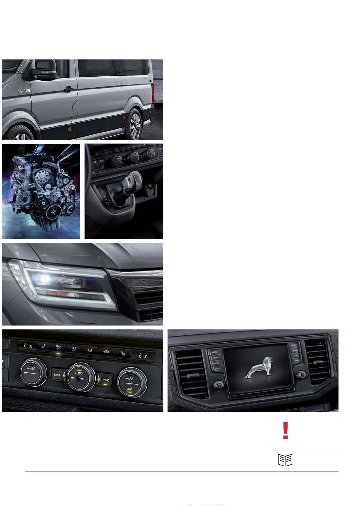
Also, there are lots of drive types. Depending on the
maximum permissible gross weight, front-wheel or
rear-wheel and all-wheel drives are possible, optionally
coupled with a 6-speed manual gearbox or an
8-speed automatic transmission. 2.0L engines with
75kW / 102 HP, 90 kW / 122 HP, 103 kW / 140 HP,
and 130 kW / 177 HP are available.
With its standard emergency brake assist (EBA), MAN
considerably contributes to road-traffic safety. To this
effect, distance sensors review critical distances to the
vehicle in the front, helping reduce the stopping distance. In addition, the integrated city emergency brake
function automatically decelerates the vehicle at low
speeds and thus reduces one of the most frequent
causes of accidents. The adaptive cruise control
system provides great convenience on long highway
distances. The fatigue detection system and the
multi-collision brake have been designed for the safety
of everybody.
m001_002
2
Page 3
CONTENTS
4 INTRODUCTION
14 VEHICLE BODY
16 POWER UNITS
14
22 POWER TRANSMISSION
30 RUNNING GEAR
16
38 ELECTRICAL SYSTEM
22
52 HEATING AND AIR
CONDITIONING
59 RADIO, TELEPHONE AND
NAVIGATION
38
52
The MAN TGE Guide teaches the basics of design and function for sales and after-sales of new vehicle models, new
vehicle components or new technologies.
The MAN TGE Guide is not a sales manual and not a repair guide! The specified values are for the sake of ease of
understanding only and refer to the data status valid at the time the MAN TGE Guide was created.
The contents are not updated.
For customer advice, maintenance and repair work, please use the appropriate technical literature.
59
Note
Reference
3
Page 4
INTRODUCTION
Die Trucknology Generation
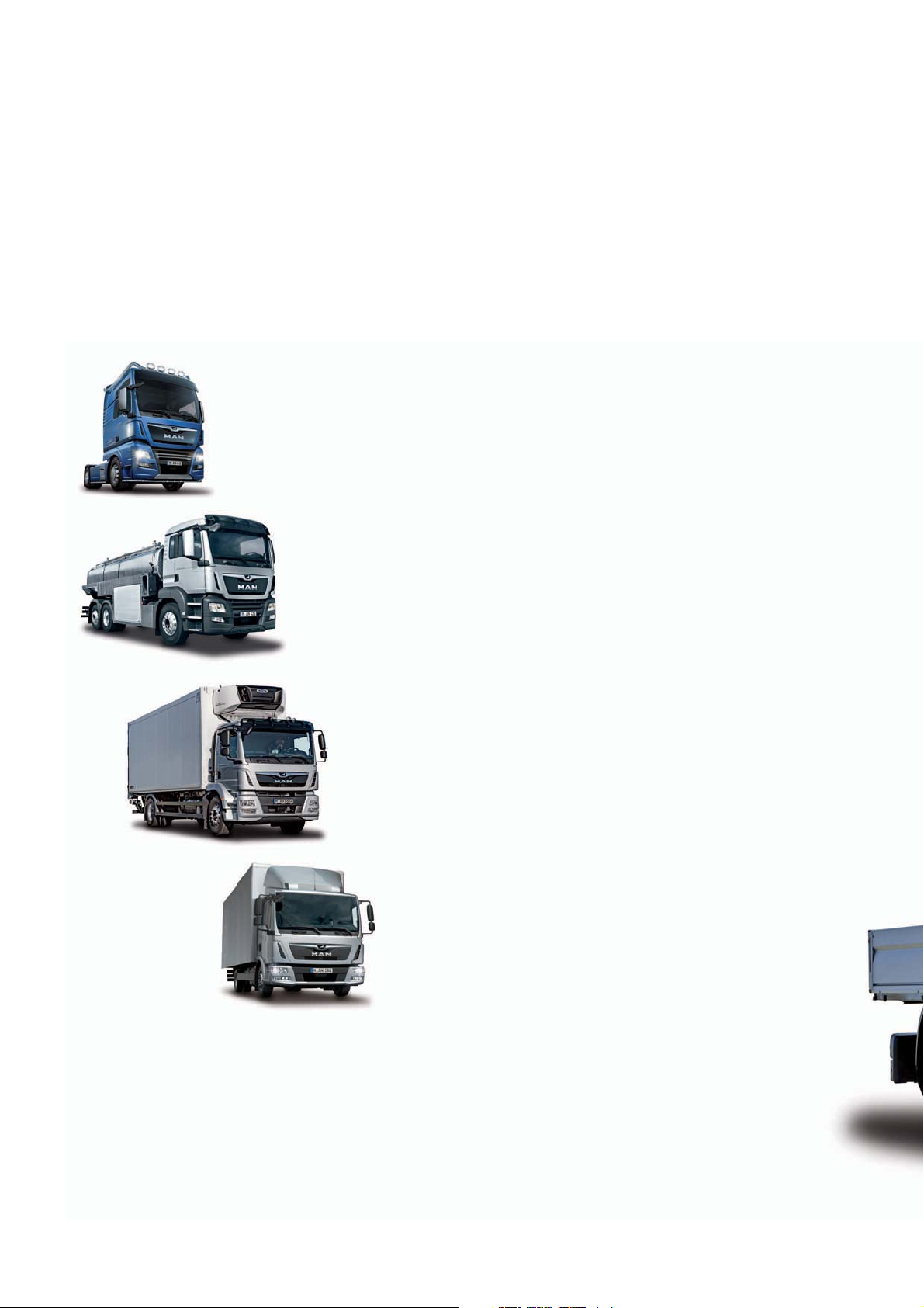
With the newly developed MAN TGE, MAN Truck & Bus is now for the first time making its commercial vehicle expertise in the
range from 3.0 to 41 tons (50 tons) available to all customers, as a full-range supplier.
The TGX, TGS, TGM and TGL series offer the customer the optimum vehicle base for individual transport solutions with total
weights from 7.49 to 41 tons (50 tons) and engine outputs from 150 hp to 640 hp. The MAN TGE now rounds this off between
3.0 and 5.5 tons total weight and an engine output of 105 hp to 175 hp and three drive variants.
MAN TGX To be successful in international long-
distance traffic, to shift up a gear in terms of transport
performance and to put the brakes on costs. This is what
the MAN TGX stands for, setting the standard for maximum
energy efficiency, reliability and economy with its exhaust
gas-optimized engines of up to 640 hp.
MAN TGS The MAN TGS is uniquely versatile:
Whether for heavy-duty local transport, on construction sites,
in municipal transport or as a specialist for special tasks, the
xxx is a versatile truck that is perfectly tailored to every sector
of industry.
MAN TGM In distribution traffic and also in
medium-heavy traction traffic, the MAN TGM is heavily
involved. With tonnages of between 13 and 26 tons and a
first-class payload, it offers economical transport solutions
for construction sites.
MAN TGL The MAN TGL is the solution for fresh
produce, construction, municipal use, furniture transport,
trade and industry. The 7.49 to 12 ton trucks are very
manoeuvrable and combine maximum payload with
dynamic driving characteristics.
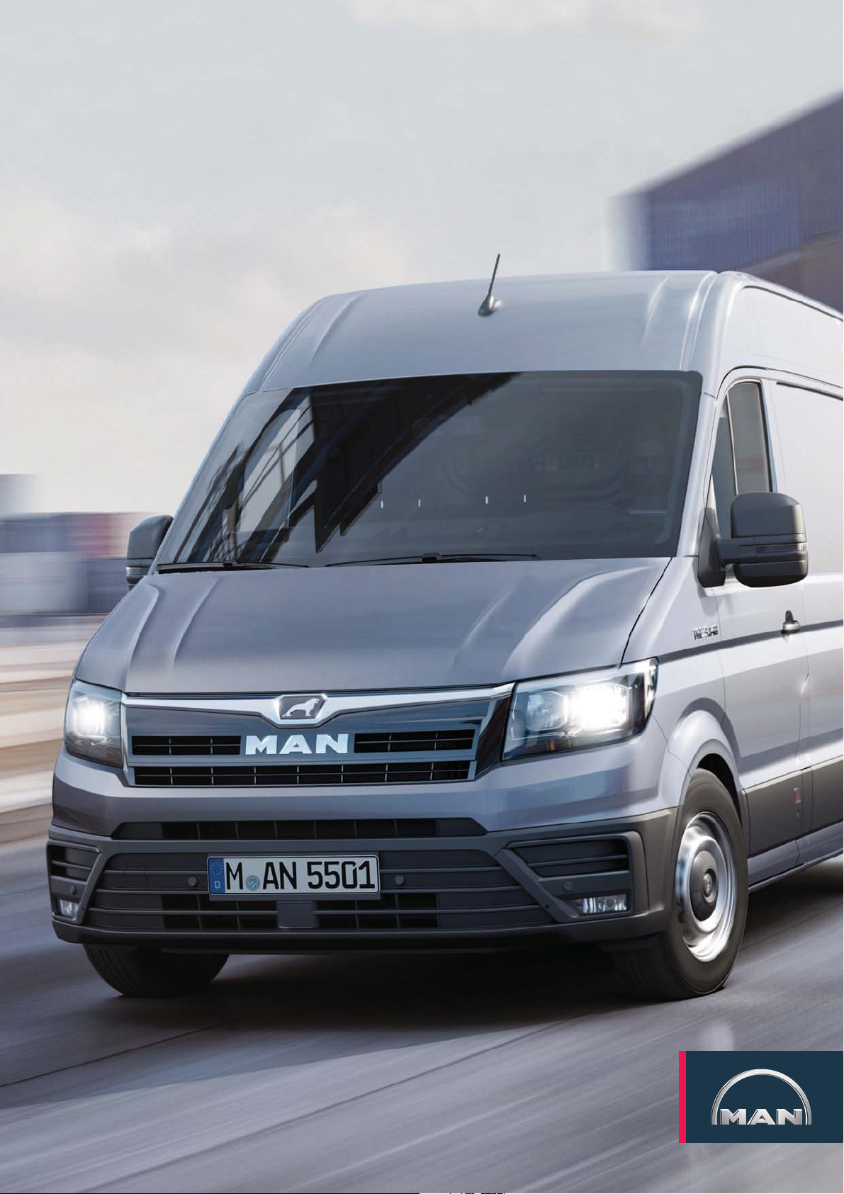
The MAN TGE with its powerful commercial vehicle roots is ideally
equipped to meet the diverse challenges of the transporter market from 3.0 to 5.5 tons.
The MAN TGE always offers the right solution for tough everyday working conditions, be
it in the forest, on the construction site or in the confusing urban jungle. With its outstanding driving comfort, numerous assistance systems and a driver‘s cab at passenger car
level, it is the new benchmark in the transporter segment.
MAN TGE
4
Page 5
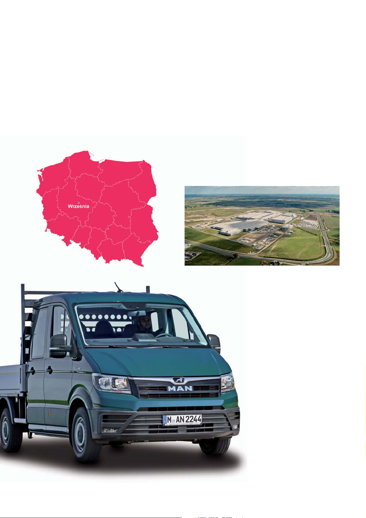
The production site
Since the laying of the foundation stone
in November 2014, Europe‘s most
modern plant of this kind has been built
in Wrzesnia, a city with around 30,000
inhabitants about 50 kilometres east of
Poznan, in just 23 months.
The production of the MAN TGE began
here on April 3, 2017, of which 100,000
units per year are to be produced by up
to 3,000 employees, together with the
identical VW Crafter.
In addition to the production halls for
vehicle assembly, a modern paint shop
and a supplier park with logistics areas
were built on the site. The development
of the supplier network and the service
sector has also created numerous new
jobs in the vicinity of the plant.
m001_216
m001_217
m001_215
5
Page 6
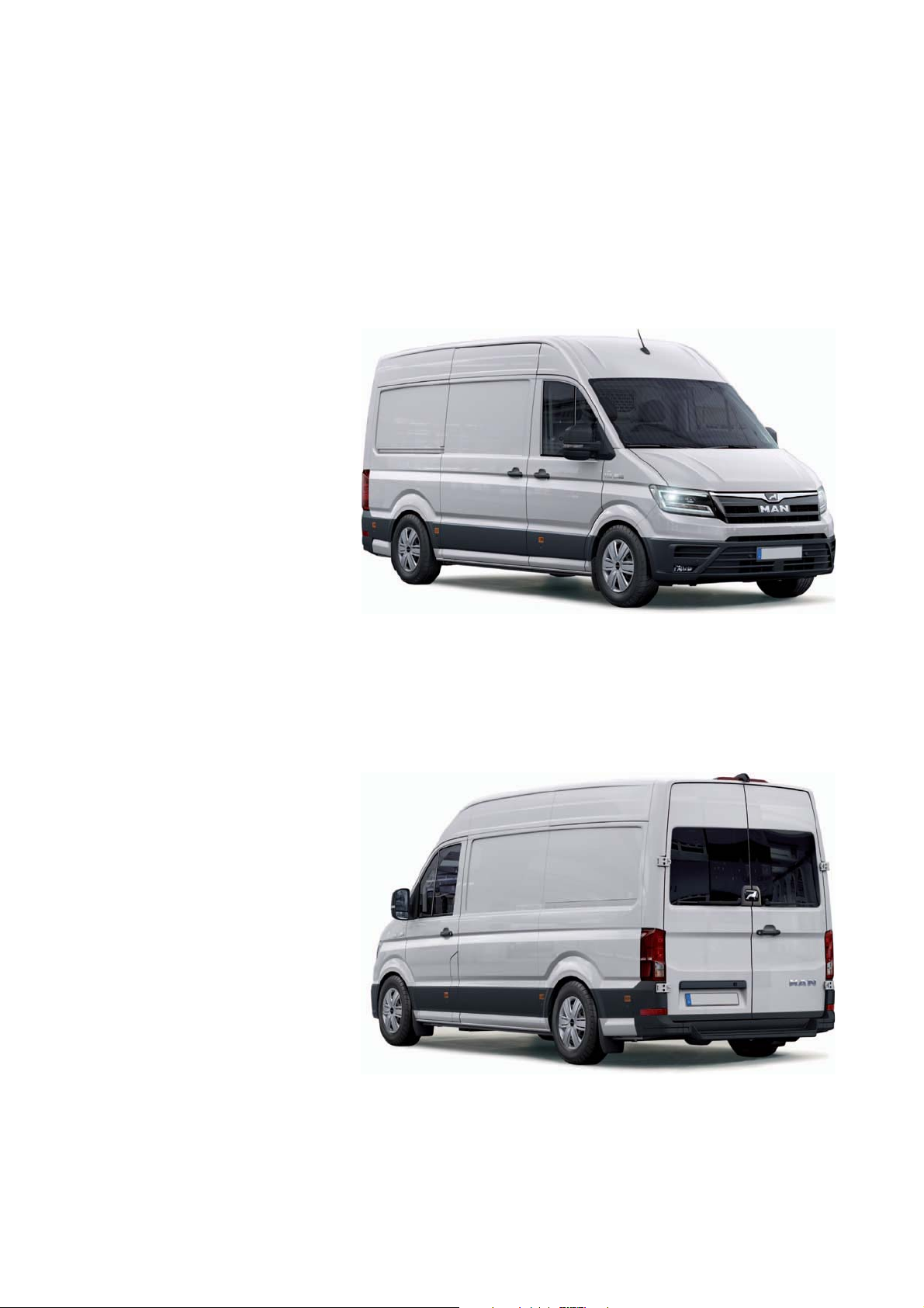
The product features of the MAN TGE
The following overview shows the 25 most important unique selling propositions and „Best in Class“ characteristics.
The safest transporter in its class thanks to versatile equipment and assistance
systems:
Emergency brake assistant as standard
Automatic Post-Collision Braking System
Automatic Distance Control (ACC)
Trailer manoeuvring assist
Lane departure warning
Lane change assistant with parking assistant
Cornering light
Headlights in LED technology
Side wind assistant
ESC with combination stabilization
Most comfortable driver‘s workplace:
Well designed storage compartment concept
Ergonomic seats with optional massage function
230 V socket in the cab
Innovative media systems
Clear displays and instruments
m001_004
Economy to the limit:
State-of-the-art engine-gearbox configurations
Streamlined body shape
Lightweight construction in every detail
Integration into fleet management systems
Versatile solution for every application:
Front, rear and all-wheel drive
Manual and automatic transmissions
Three possible vehicle lengths
Three possible roof heights
Four different body shapes
Universal floor with preparations for built-in
components
Optional longitudinal and transverse rails in the loading floor
Rear end free from technical equipment for various conversion
solutions
m001_005
6
Page 7

The notable characteristics of the MAN TGE
Vehicle front in striking MAN family
design
Modern workstation with ergonomic control panel and clearly
arranged instruments
LED headlights
Adjustable driver and front
passenger seats – also as
swing seat and AGR seat
(with seal of approval from the
campaign for healthy backs)
with electrical lumbar support
Loadspace with universal floor and a
wide variety of installation options
Tail light clusters with connecting character line
m001_082
7
Page 8
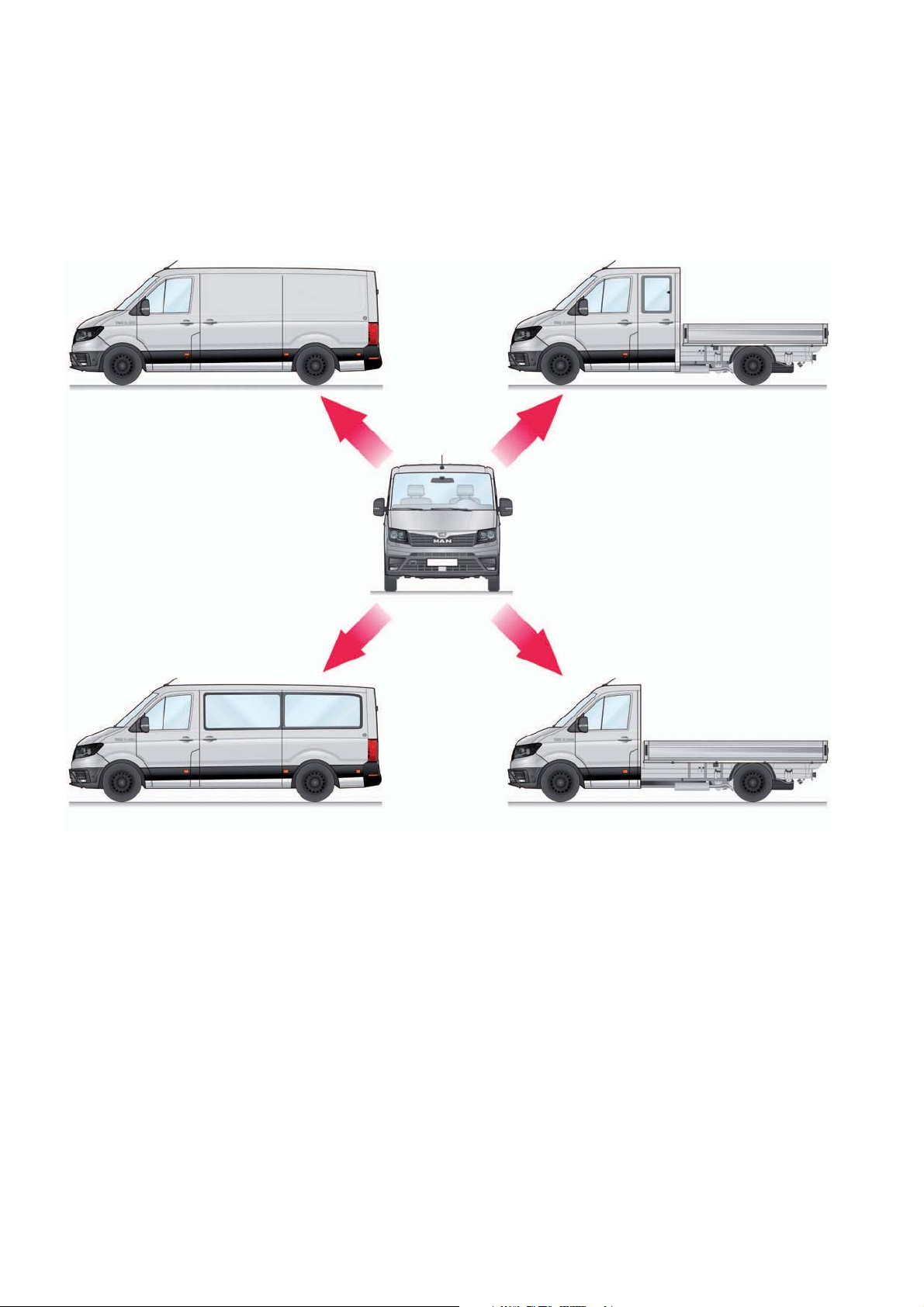
Derivatives
Panel van Double cab
Window van Single cab
The MAN TGE has an extensive range
of models to choose the vehicle best
suited to customer requirements. In
total, there is a choice of 69 body and
powertrain variants.
The four basic variants panel van,
window van and platform van with
single or double cab meet the highest
demands in their respective customer
segments.
The individual body shapes can be
further customized with different wheel
bases and roof heights.
In addition to the standard body
shapes, the following derivatives are
also available for extensive customeroriented special configurations:
Carriage with flat frame chassis
Cowl panel
Platform
m001_218
8
Page 9
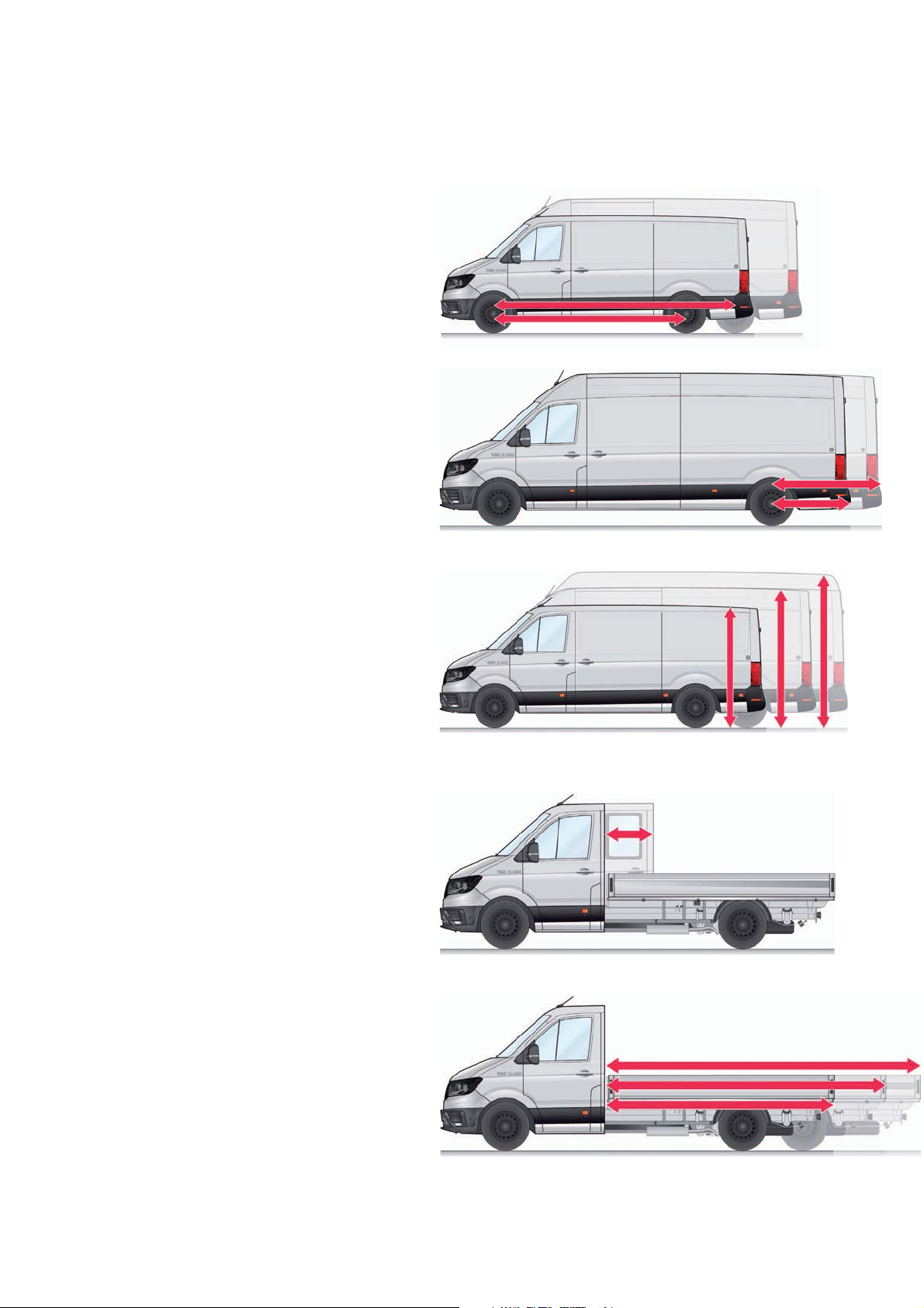
Dimension variants
Wheelbases
Two wheelbases are available.
Standard wheelbase: 3640 mm (L3)
Long wheelbase: 4490 mm (L4/L5)
Rear overhangs
Two rear overhang lengths are available
for the long wheelbase.
Long: 1346 mm (L3/L4)
Extra long : 1901 mm1) (L5)
Roof heights (panel van, window van)
Three roof heights are available.
m001_219
m001_220
Normal roof: 2355 / 2390 mm2) (H2)
High roof: 2590 / 2625 - 2637mm 2) (H3)
Super high roof: 2798 / 2830 - 2835
1), 2)
mm (H4)
Cabs (platform van, chassis)
Two cab sizes are available for the transport of additional
persons:
Single cab with maximum seat configuration 2+1
Double cab with maximum seat configuration 6+1
Platform lengths
Ex factory, three platform lengths are available with single cab (SC) and a further
platform length for double cab (DC).
m001_221
m001_222
Standard single cab: 3500 mm
Long single cab: 4300 mm
Extra long single cab: 4700 mm
Standard double cab: 2700 mm
Long double cab: 3500 mm
1)
Not with window van.
2)
Single/twin tyres
m001_223
9
Page 10
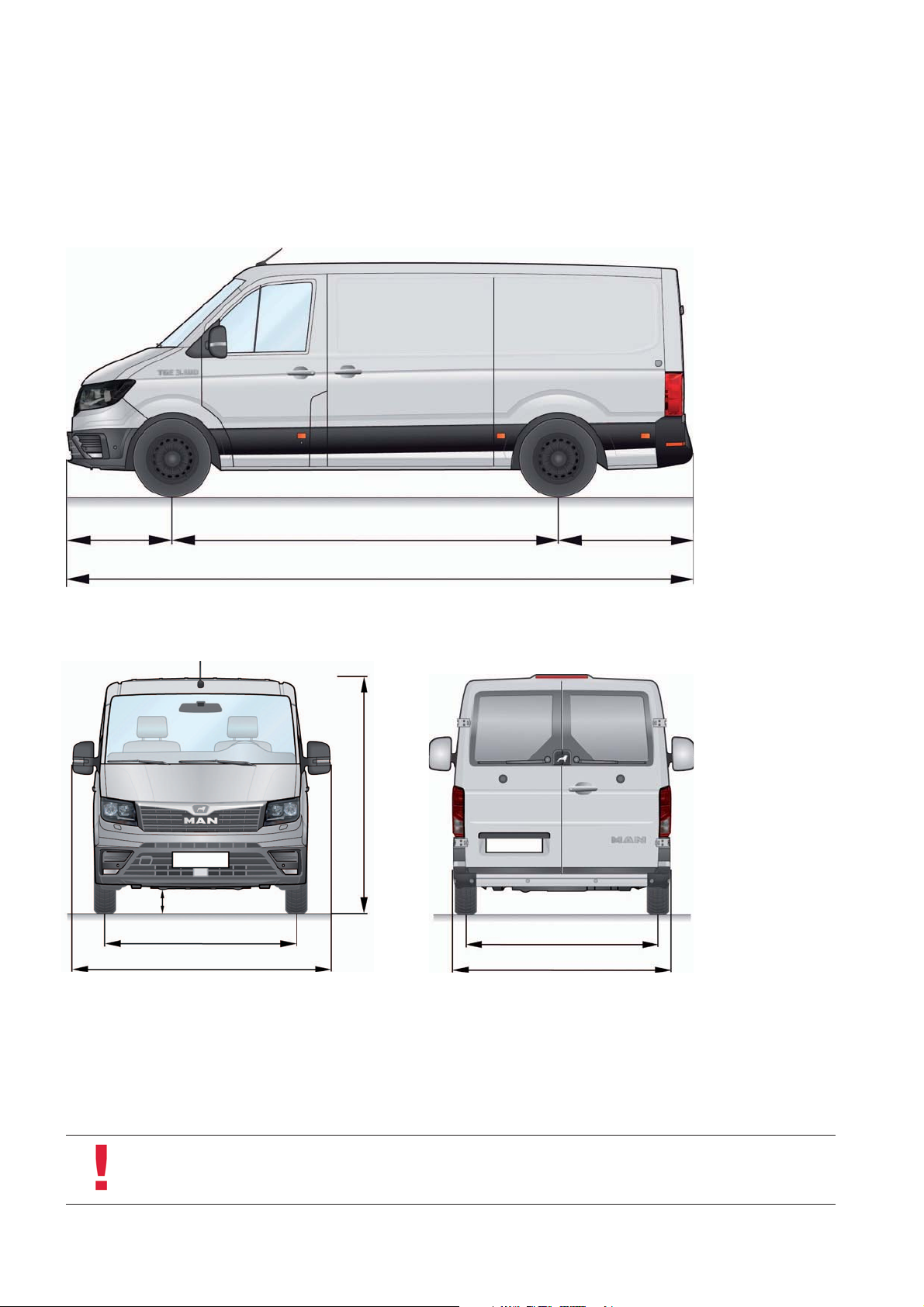
Technical data
Panel van, window van
3640 – 44901000 1346 – 1901
5986 – 7391
m001_224
210 / 214
1773
2425 – 2427
All figures are in millimetres.
Note
The illustrations only show selected variants and their dimensions/dimension areas. For the complete technical data
for the entire model range, please refer to the current sales literature.
10
2355 – 2835
1)
1)
1)
m001_008
m001_225
1766 – 1788 / 1601
2040 / 2069
1)
Single/twin tyres
Page 11

Single cab, double cab
1000 3640 – 4490 1514 – 1914
3500 – 4700
6204 – 7404
m001_226
2321 – 2352 2305 – 2327
2700 – 3500
1000 3640 – 4490 1514 – 1564
6204 – 7004
m001_227
All figures are in millimetres.
11
Page 12
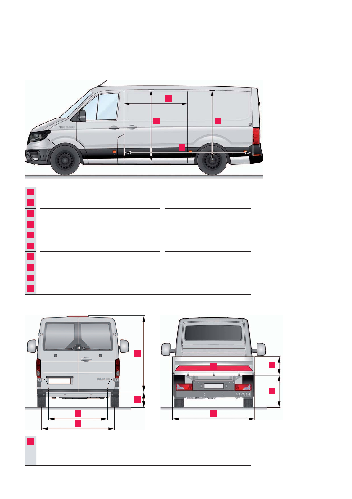
Load compartment measurements
B D
A
Sliding door width 1311
B
Sliding door height 1430 – 1587 / 1668 – 1822
C
Maximum loadspace length 3201 – 4606
D
Maximum loadspace height 1568 – 2196
E
Height of rear wing door 1451 – 1605 / 1684 – 1840
F
Loading height/loadsill 570 – 725 / 1000 – 1050
G
Maximum loadspace width 1832
H
Width between wheel housings 1375 – 1380 / 1030
I
Maximum platform height 400
J
Maximum platform width external 2098
A
C
m001_228
1)
5)
1)
2)
3)
All figures are in
millimetres for vehicles
with front-wheel drive.
1)
Normal roof / High roof,
Super high roof
2)
Panel, window / platform
3)
Single / twin tyres
4)
Front and four-wheel drive /
rear-wheel drive
5)
incl. 15 cm subfloor storage
compartment
Window van, panel van Flatbed
E
F
H
G
K
Maximum loadspace area 5,16 – 8,99 m
m001_012
Maximum trailer weight 3000 / 3500 kg
Gross vehicle weight 3500 – 5500 kg
K
I
F
J
m001_229
2
4)
12
Page 13
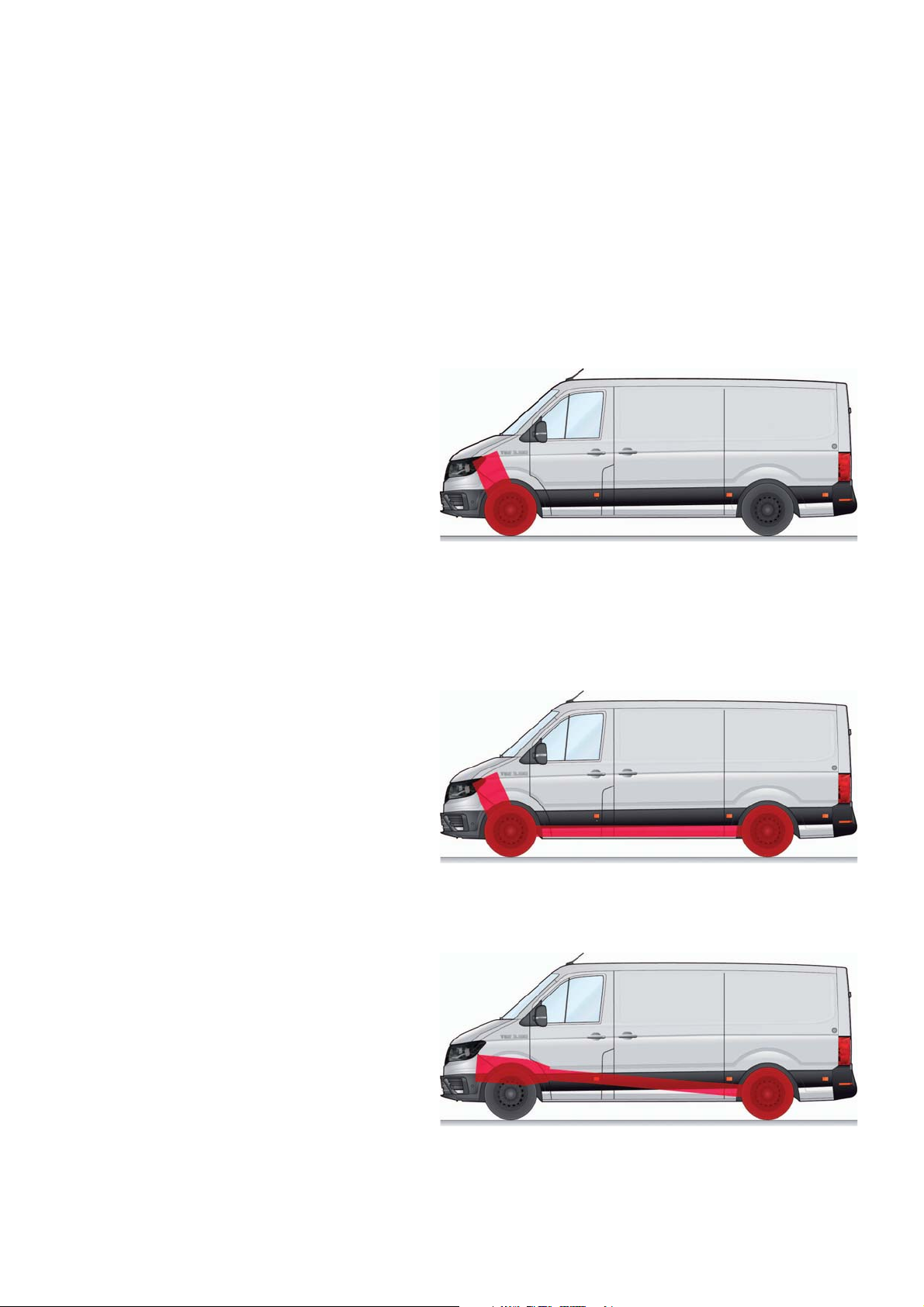
The vehicle concept
Drive system types
Prior to the development of the MAN
TGE, intensive customer surveys were
conducted and market requirements
Front-wheel drive
The drive unit is installed transversally.
Features are:
low loadspace floor (about -100 mm),
thereby increasing the loadspace
volume and reducing the loadsill
height
Rear end without drive technology
Driveline with reduced weight
(approx. 100 kg less), lower fuel
consumption
Applications include courier and
logistics services, joiners/plumbers/
glaziers, etc. and rescue services.
All-wheel drive 4x4
were taken into account in the design
process.
For the first time, three types of drive are
used in the MAN TGE and VW Crafter.
m001_230
The drive unit is installed transversally.
Features are:
Electronically controlled multi-plate
clutch
Optimum traction
Particularly suitable for regions with
poor weather conditions or roads
Applications include the building trade
and forestry as well as the police and
military.
Rear wheel drive
The drive unit is in inline installation.
Features are:
Good traction for high loads
Higher gross vehicle weight rating
possible (up to 5.5 t)
Single or twin tyres at rear
Use of auxiliary drives on the gearbox
(e.g. for body manufacturer) possible
Applications include service vehicles
and mobile workshops with heavy
built-in components as well as special
bodies.
m001_231
m001_232
13
Page 14
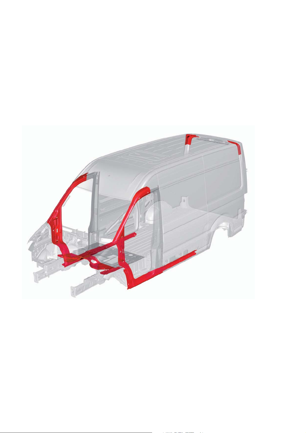
VEHICLE BODY
Body structure
The body of the MAN TGE has been
completely redesigned. In addition to
the modular design, the developers
focused on optimizing weight and
aerodynamics as well as crash safety.
These goals were achieved, among
other things, by the use of higheststrength hot-formed steels. Compared
to conventional steels, these are considerably stronger at a similar weight and
thus make the MAN TGE lighter and
safer.
The following components are made
from hot-formed steel:
Front roof side members
Sill panel reinforcement
Corner reinforcement on the rear roof
m001_083
A-pillar bottom part
Front bulkhead
Longitudinal member reinforcement
for driver‘s cab
14
Page 15
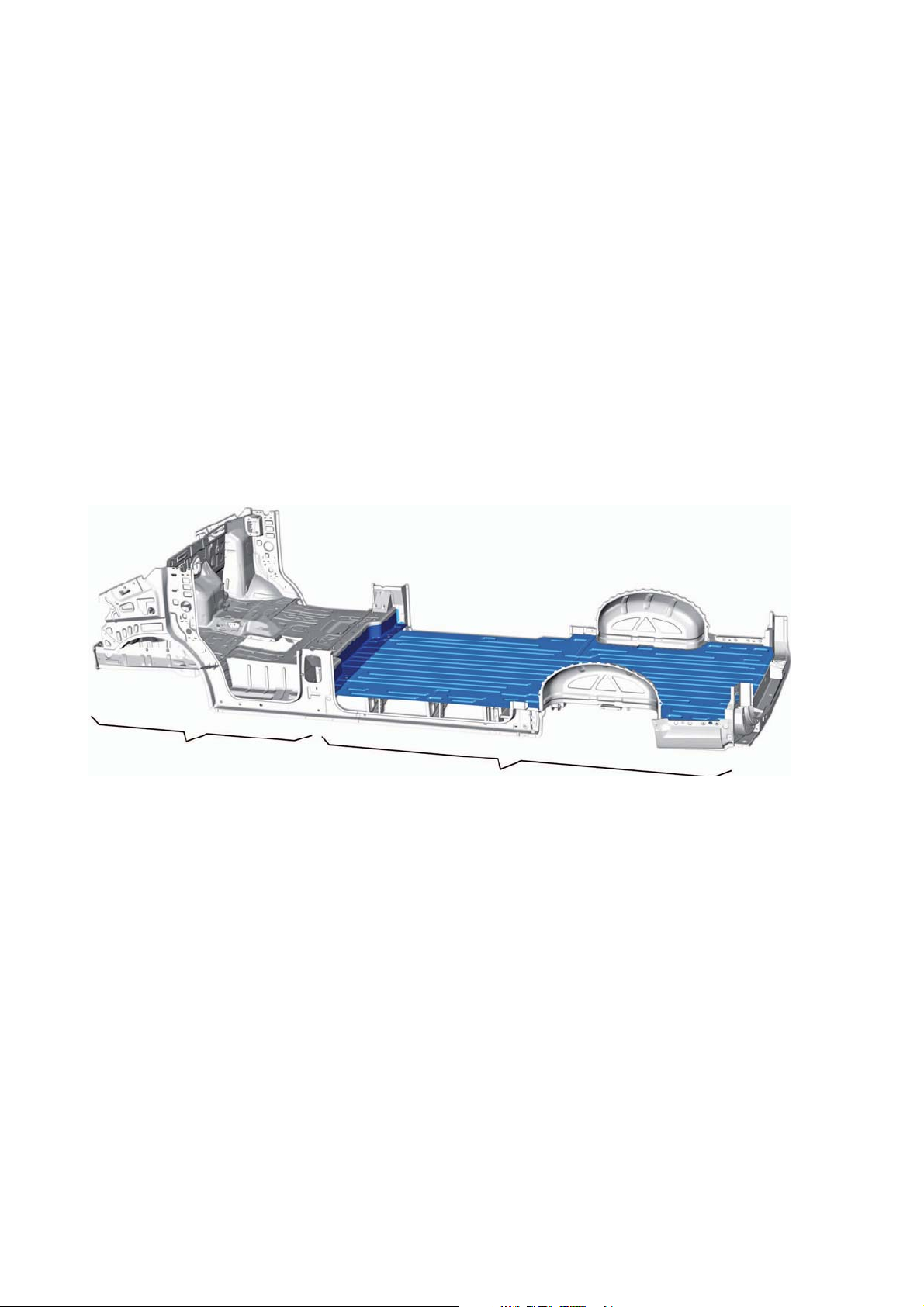
Modular structure
Use of as many identical parts as
possible was an important goal during
development of the body structure. The
objective was to allow the numerous
derivatives and variants such as different
wheelbases and roof heights to be
manufactured with great synergy
effects.
Vehicle front end the
same for all variants
Floor structure
The floor structure of the MANTGE is
the same for all variants in the vehicle
front end area. At the rear end, however,
there are significant differences regarding the floor panel, longitudinal
members, wheel housings and the
corresponding connecting parts as well
Vehicle rear end different depending on
the variant, in this case short wheelbase
with low loadspace floor (-100 mm)
as reinforcements. Their configuration
and design are determined by the
following factors:
Type of drive
Wheelbase
Rear overhang
m001_084
Type of body
Single or twin tyres on the rear axle
15
Page 16
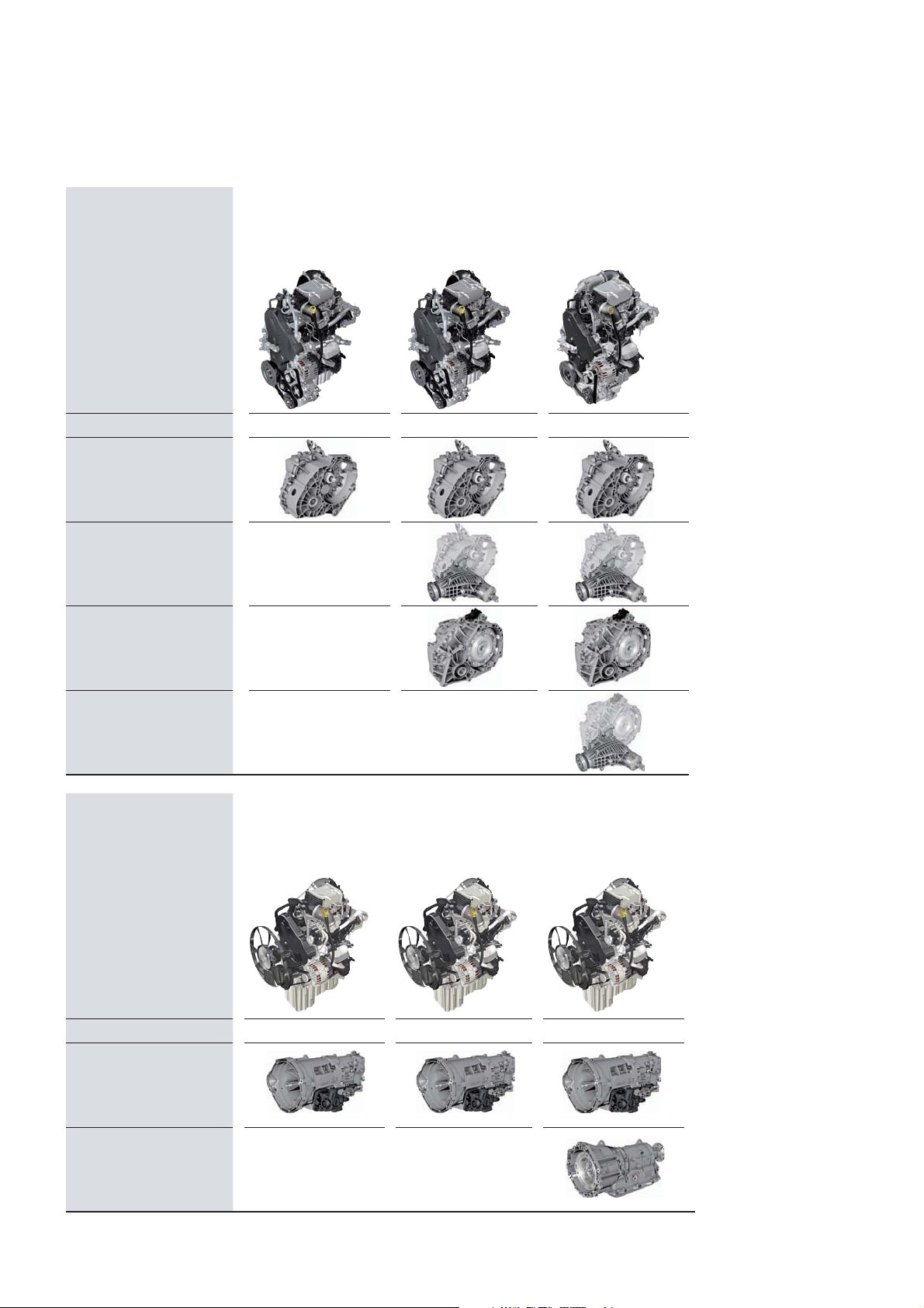
POWER UNITS
Engine/gearbox combinations
Transverse
installation
6-speed
Manual gearbox
0AX front-wheel drive
6-speed
Manual gearbox
0AX four-wheel drive
8-speed
Automatic gearbox
09Q front-wheel drive
2.0l Turbo diesel
75 kW
DAUB
2.0l Turbo diesel
103 kW
DAUA
2.0l Biturbo diesel
130 kW
DAVA
8-speed
Automatic gearbox
09Q four-wheel drive
Longitudinal
installation
6-speed
Manual gearbox
0F6 rear-wheel drive
8-speed
Automatic gearbox
0DR rear-wheel drive
2.0l Turbo diesel
90 kW
DASA
2.0l Turbo diesel
103 kW
DASB
2.0l Biturbo diesel
130 kW
DAWB
16
Page 17
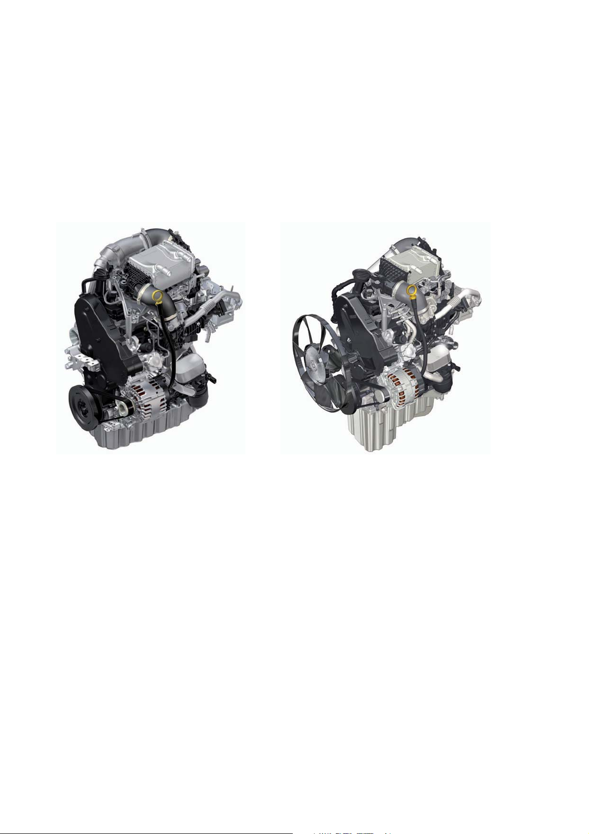
The 2.0 l turbo diesel engines
In the MAN TGE, only 2.0-litre turbo diesel engines from the MDBnutz modular diesel construction kit are used. The use of a
uniform engine geometry with many identical parts creates high synergy effects and reduces manufacturing and maintenance
costs.
Transverse installation Longitudinal installationtion
m001_140 m001_141
The engines of the MAN TGE have been
specially designed for commercial
vehicles to meet the high requirements
in terms of mileage, driving resistance,
driving profile and service life.
Adjustments were made, for example,
to the intercooling, the cylinder head,
the variable-length intake manifold, the
EGR cooler, the turbochargers and the
oil pan.
The installation position is adapted to
the commercial vehicle design.
Depending on the drive concept used,
the engines are installed transversely or
longitudinally - an absolute special
feature within a vehicle series.
In addition, transversely installed
engines are installed at an angle of 8° to
the front in order to make optimum use
of the available installation space.
Longitudinally installed engines have a
larger oil pan and an increased oil
quantity.
Engines with one or two turbochargers
are used. A total of up to four power
stages are available, ranging from 75
kW to 130 kW. The after-treatment of
the exhaust gases is carried out by an
SCR system for nitrogen oxide reduction. Additional options, e. g. different
generators and compressors, are
possible with the accessory drive used.
17
Page 18
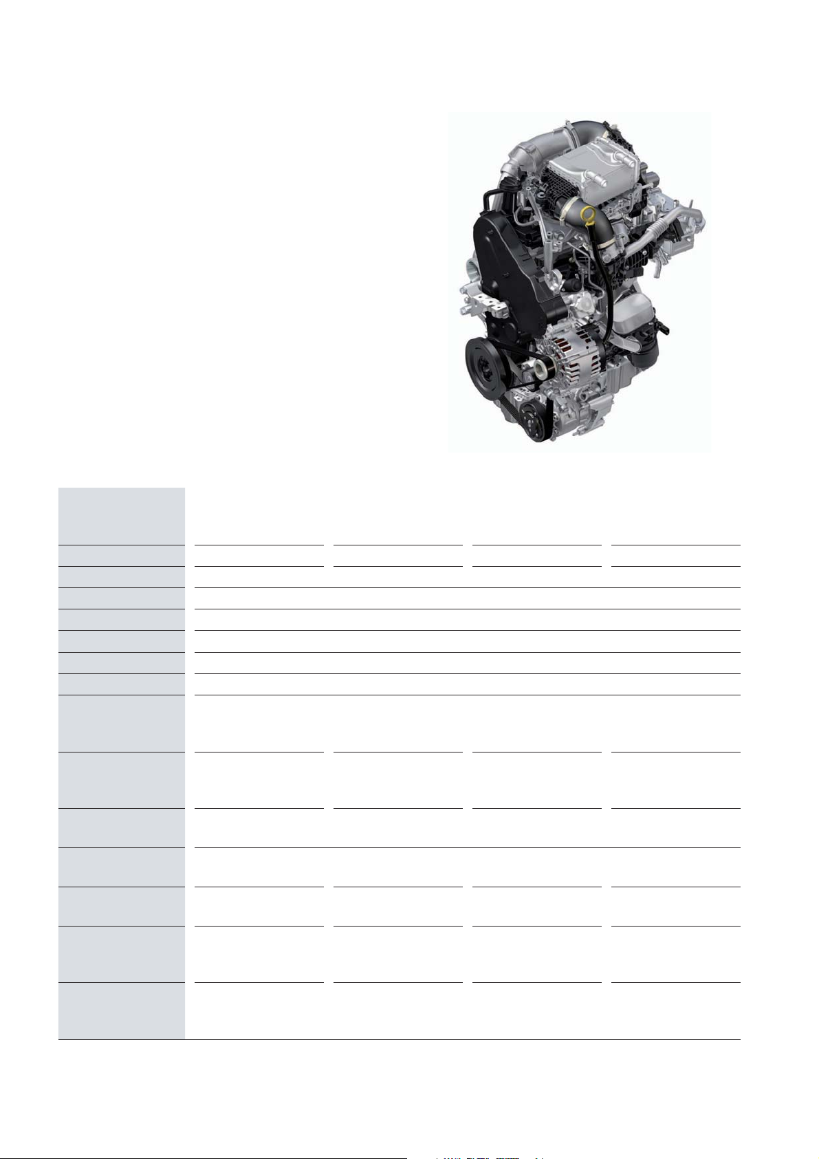
Technical data
The engine is part of the engine series EA288nutz and
is installed in this design – beside the MAN GTE – only
in the VW Transporter and Crafter. The engine is
available in the EU6 plus and EURO VI exhaust emission standards, depending on the application.
Technical features
Liquid-cooled charge air cooler
High-pressure exhaust gas recirculation
Delphi common rail direct injection
Liquid-cooled injector for reducing agent
Injectors with solenoid valve
Single-plunger high-pressure pump (monoturbo),
double-plunger high-pressure pump (biturbo)
m001_052
Motor designation 2.0 l Turbo diesel
75 kW
Engine code DAUB DASA DAUA / DASB
Capacity 1968 cm
Type 4-cylinder in-line engine
Valves per cylinder 4
Bore 81.0 mm
Stroke 95.5 mm
Compression ratio 15.5 : 1
Maximum output
at rpm
Max. torque
at rpm
Engine management Delphi DCM6.2
Fuel DIN EN 590 DIN EN 590 DIN EN 590 DIN EN 590
Forced induction Mono turbo Mono turbo Mono turbo Biturbo
75 kW
at 3250 – 3500
300 Nm
at 1400 – 2250
2.0 l Turbo diesel
90 kW
90 kW
at 3250 – 3500
300 Nm
at 1400 – 2250
2.0 l Turbo diesel
103 kW
1)
3
103 kW
at 3500 – 3600
340 Nm
at 1600 – 2250
2.0 l Biturbo diesel
130 kW
DAVA / DAWA
130 kW
at 3600
410 Nm
at 1500 – 2000
Exhaust gas
recirculation
Emission standard
1)
Longitudinal/transversal
2)
EU6 plus: Light duty homologation <2840 kg reference weight (roller test bench)
EURO VI: Heavy duty homologation >2380 kg reference weight (engine test bench)
18
yes yes yes yes
2)
EU6 plus EURO VI EU6, EU6 plus EU6, EU6 plus,
EURO V/VI
Page 19
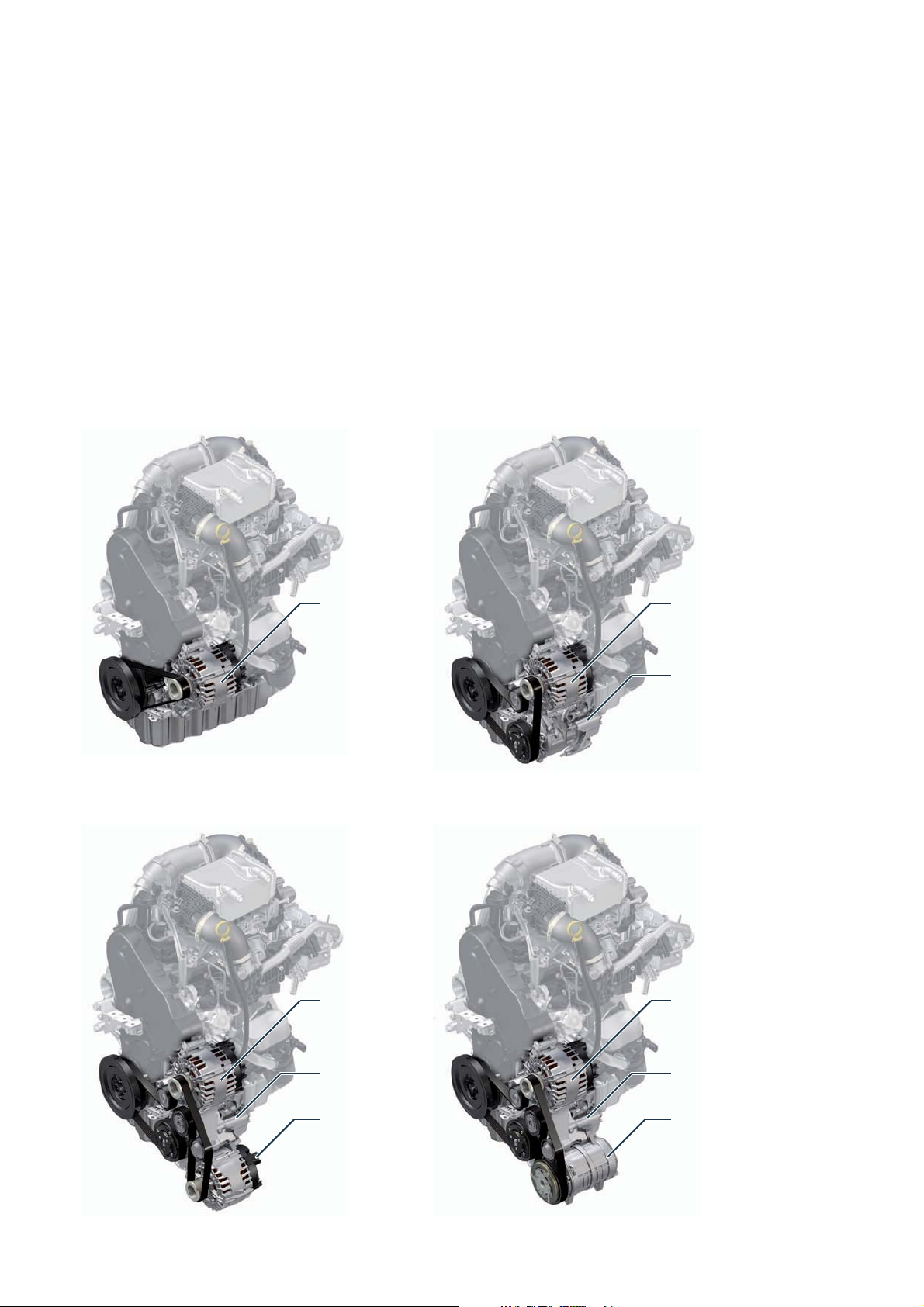
Ancillary drive
An ancillary drive with modular expansion capability is used in response to
the wide variety of customer requirements. In addition to the usual units
such as an alternator and air conditioner
compressor, it is also possible to drive
an additional air conditioner compressor
or additional alternator. In vehicles with
bodies such as camper vans or refrigerated vans, this allows the required form
of energy to be provided, e.g. for air
conditioning, cooling or driving electrically operated ancillaries.
An elastic belt alone is used as the poly
V-belt in an engine with alternator. In all
other variants, the poly V-belt is tensioned using a belt tensioner.
Basic drive Air conditioning drive
Alternator
(various
power levels)
Alternator
(various
power levels)
Air conditioner
compressors
Additional drive
m001_053 m001_054
Alternator
(various
power levels)
Air conditioner
compressors
Additional
alternator
(in 180 A version)
Alternator
(various
power levels)
Air conditioner
compressors
Additional air
conditioner
compressor
m001_055 m001_056
19
Page 20
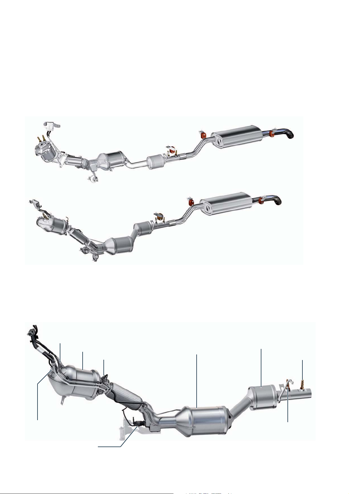
Exhaust system
The exhaust system of the MANTGE is available in various variants. Its structure depends on the engine or body variant, for
example.
Inline installation, EU6
Transverse installation, EU6
m001_058
Exhaust gas treatment
In vehicles with SCR system (EU6 exhaust standard), there is a lambda probe (oxygen sensor) in the front part of the exhaust
pipe as well as three temperature sensors, the injector for reducing agent as well as the corresponding catalytic converters.
Lambda probe
Oxidising catalytic converter
Temperature sensor 3
Temperature sensor 2
Diesel particulate filter
with SCR coating
Trap catalytic converter
Particle mass sensor
sensor
NO
x
20
Injector for reducing
agent N474
m001_060
Page 21

Reducing agent tank
In addition to the fuel tank with a capacity of about 75 litres, there is a tank
with a capacity of about 18 litres of
reducing agent (AdBlue). The reduction
agent consumption depends on the
individual driving style, the operating
temperature of the system and the
ambient temperature.
The tank for reducing agent is replenished via the filler neck for reducing
agent under the fuel filler neck, and is
sealed by a blue tank cap. The tank for
reducing agent is located on the underbody ahead of the fuel tank. A compensation volume has been integrated in
the top part of the vent in order for the
reducing agent flowing in at high speed
to be filled.
m001_061
Fuel filler neck Filler neck for reducing agent
Body
Control unit for reducing
agent heating
J891
Breather diaphragm
Breather line Filler pipe
Expansion section
Filler line
Reducing agent tank
Pump module with:
Heating
Sender for reducing agent tank G697
Filter
m001_062
21
Page 22

POWER TRANSMISSION
Overview
The diverse drive concept means there
are also several variants of power
transmission. The range extends from
straightforward front-wheel drive with
Rear final drive 0AY
manual gearbox through to four-wheel
drive and rear-wheel drive with an
auxiliary drive on the gearbox for additional working implements. In vehicles
with front or four-wheel drive, the
gearbox is installed transversely
whereas vehicles with rear-wheel drive
have an inline gearbox installation.
Electronically controlled multi-disc clutch /
5th generation four-wheel drive coupling
Rear final drive
Vehicles with rear-wheel drive are equipped with rear
axle drive 0HA. Vehicles with all-wheel drive 4x4, on
the other hand, are equipped with a rear axle drive with
four-wheel drive coupling
m001_191
m001_190
Final drive 0HA Rear final drive with four-wheel drive coupling
22
Page 23

Selector mechanism
The gears are changed using a joystick gearshift on
the dash panel. In vehicles with manual gearbox, a
gearshift recommendation is shown on the display of
the instrument cluster.
The automatic gearbox selector lever has a Tiptronic
manual shifting mode. The Tiptronic gear selector lever
has the normal arrangement of speeds as in an automatic transmission in the left row, with a connection to
a second parallel row on the right. In this second row,
shifting is performed one step up (+) or down (-) by
pressing the selector lever. The current selector lever
position is shown on the display of the instrument
cluster.
Selector lever
position display unit
m001_114
Interlock button on
selector lever
Selector lever
position display unit
Selector mechanism via cable
8-speed automatic gearbox 09Q
Final drive gear
m001_072
23
Page 24

The gearboxes
6-speed manual gearbox 0AX
This transmission is used in front wheel
drive or 4x4 four-wheel drive vehicles.
Front-wheel drive All-wheel drive 4x4
For use in the MAN TGE, it was
adapted with respect to gear ratios and
to the installation space-specific conditions.
In the MAN TGE, it is used both for front
wheel drive, and with a flange-mounted
angle drive for 4x4 all-wheel drive.
Final drive
gear
Developer/manufacturer
Transmission designation
Gearbox features
Torque
m001_045 m001_046
Volkswagen AG
MQ500-6A/-6F im
Service code: 0AX
6-speed manual gearbox with four shafts and cable operation for front or fourwheel drive in transverse installation
410 Nm
24
Page 25

8-speed automatic gearbox 09Q
The newly developed automatic transmission is used in front wheel drive or
4x4 four-wheel drive vehicles.
Front-wheel drive All-wheel drive 4x4
For use in the MAN TGE, care was
taken to ensure a robust design of the
converter, gearbox housing, differential
and parking lock.
In all-wheel drive vehicles, the drive to
the rear axle is provided by a flangemounted angular drive.
Final drive
gear
Developer/manufacturer
Transmission designation
Gearbox features
Torque
m001_047 m001_048
AISIN AW CO., LTD Japan
AQ450-8A/-8F
Service code: 9Q
Electrohydraulically controlled 8-speed planetary gearbox (automatic rangechange
gearbox) with hydrodynamic torque converter and limited-slip torque converter
lock-up clutch for front or four-wheel drive in transverse installation
410 Nm
25
Page 26

6-speed manual gearbox 0F6
The newly developed manual transmission is used in rear-wheel drive vehicles.
For the MAN TGE it has been designed
with a correspondingly robust layout.
This applies, for example, to the design
of bearings and synchronization. A
gearbox-side power take-off is available
as an option.
Developer/manufacturer
Transmission designation
Gearbox features
Torque
m001_138 m001_049
PTO
ZF Friedrichshafen AG
ML410-6H
Service code: 0F6
2-shaft manual gearbox with single and multi-synchronised gear stages. The
gearbox comprises an input shaft in conjunction with a coaxial output shaft, as well
as a layshaft and a reverse shaft for reverse gear. The auxiliary drive is driven via
the layshaft.
410 Nm
26
Page 27

8-speed automatic gearbox 0DR
The newly developed automatic transmission is used in rear-wheel drive
vehicles.
For the MAN TGE it has been designed
with a correspondingly robust layout.
This concerns e. g. the converter and
the planetary gear set.
In addition, the gearbox housing, lining
plates, plate supports and the parking
lock are reinforced.
Developer/manufacturer
Transmission designation
Gearbox features
Torque
m001_050
ZF Friedrichshafen AG
AL550-8H
Service code: 0DR
Electro-hydraulically controlled 8-speed planetary gearbox with hydrodynamic
torque converter and torque converter lock-up clutch with controlled slip
410 Nm
27
Page 28

Four-wheel drive coupling
The four-wheel drive coupling in the
rear-wheel drive corresponds to the
5thgeneration of electrohydraulically
controlled four-wheel drive couplings.
It is available either with or without a
differential lock in the MAN TGE.
The differential lock is operated using an
electrically driven actuator.
Four-wheel
drive coupling pump
V181
m001_075
Final drive, here without
differential lock
5th generation four-wheel
drive coupling
Propshafts
Depending on the wheelbase, different
propshafts are used in vehicles with rear
or four-wheel drive. In a short wheel-
Four-wheel drive control
unit J492
base, a propshaft with a universal joint
transmits the drive force to the rear axle,
whereas in a long wheelbase there is a
Short wheelbase
propshaft with two universal joints,
which is also configured in two parts.
Long wheelbase
28
m001_074
Page 29

PTO
An auxiliary drive on the gearbox side is used if high
power is required over a longer period. The manual
gearbox 0F6 (only in vehicles with rear-wheel drive) can
optionally be equipped with an auxiliary drive for driving
additional external devices, such as:
Hydraulic pumps, e.g. for crane/tipper
External underfloor generators
Compressors, e.g. for high-pressure washers
Drain flushing pumps
The auxiliary drive is activated by an electric shift
cylinder. The power is taken off at the side of the
gearbox. The auxiliary drive is available in three different variants:
Power take-off without flange
Auxiliary drive with flange
Auxiliary drive with four-hole adapter sleeve, e.g. for
axial piston pumps
Optionally, the auxiliary drive can be equipped with
additional gear oil cooler for higher power output. In
this case, the transmission has a higher oil quantity.
Observe the notes in the repair instructions and the
assembly guidelines.
Return pipe
Gear oil cooler
Oil temperature controller
(Thermostat)
Shift cylinder for
auxiliary drive
Feedback switch
Supply pipe
m001_135
Intake line
Gear oil pump
Flange for connection
to the manual gearbox
Operation
The auxiliary drive is switched on by button E225. The
optional working speed governor can be engaged
using button E261 when the auxiliary drive is switched
on.
Switch-on conditions:
Road speed = 0 km/h
Parking brake applied
Neutral detected
Engine running (max. 1040 rpm)
Press button E225 and hold it for 2 to 5 seconds
The auxiliary drives is engaged if the clutch is
depressed within 10 seconds following activation
using button E225.
Switch-off condition: press clutch
Power take-off without flange Output shaft
Switch module on left
next to the steering wheel
Button for working
speed governor
E261
Button for auxiliary drive
E225
m001_081
m001_076
29
Page 30

RUNNING GEAR
Overview of the chassis
The overview shows important running gear equipment of the MANTGE that is fitted as standard and optionally. The different
drive concepts mean there have also been corresponding adaptations in the running gear.
Running gear
Technical features
Three-point assembly mountings with
subframe
McPherson strut front suspension
Rear axle as rigid axle with leaf
springs in four variants
16-inch disc brake system front and
rear
17-inch disc brake system front and
rear with 5.5 t
Brake system ESC/ABS 9.2
McPherson suspension struts
in vehicles with rear-wheel drive,
single or twin tyres are an option on
the rear axle
Electromechanical power steering
30
Electromechanical power steering
Drive assembly carrier
Page 31

Disc brake system rear
Rigid axle with leaf springs
(for front-wheel drive)
Parking brake
with folding actuating lever
m001_139
31
Page 32

Overview of the driver assist systems
Available driver assist systems
With about 20 assistance systems, the MAN TGE is the best in its class.
It is the only transporter equipped with the emergency brake assistant as standard; thus, it makes an important contribution to
general road safety.
A special highlight are the various parking
assistants from the side protection via the
parking steering assistance to the trailer range
assistant.
.
Automatic Distance Control (ACC) Main beam assistant
Emergency brake assistant (series))
Automatic Post-Collision Braking
System (series)
Main beam assistant
Automatic Distance Control (ACC))
Trailer manoeuvring assist
Side wind assistant
Speed control system incl. speed
limitation system
Parking assistant
Tire pressure control system
Rain/light sensor
Driver Alert System (DAS)
Park assist steering
Lane departure warning (Lane Assist)t
Traffic sign detection (Sign Assist)
Lane change assistant
Flank protection
Reversing camera (Rearview Camera
System)
Assist system for reversing out of
parking spaces (Rear Cross Traffic
Alert)
Hill Start Assist
Side wind assistant
Assist system for reversing out of
parking spaces (Rear Cross Traffic
Alert)
32
Page 33

Automatic Post-Collision Braking
System
Optical 360° parking system (OPS)
with flank protectionz
Lane departure warning Lane change assistant
Trailer manoeuvring assist
m001_233
Traffic sign detection (Sign Assist)
Hill Start Assist Reversing camera (Rearview
Park assist steering
Camera System)
33
Page 34

Front axle
The front axle in the MAN TGE has a
drive assembly carrier to which the
transverse links are connected. The
drive assembly carrier is bolted to the
body via several mounting points. The
anti-roll bar is located ahead of the axle
McPherson suspension
struts
Electromechanical power steering
and is connected via coupling rods to
the McPherson suspension struts
Coupling rod Anti-roll bar Drive assembly carrier Transverse link
Trim on the transverse left
The aerodynamic package includes underbody paneling and aerodynamic trims at the transverse links. The
clipped-in trims contribute to reducing the drag coefficient and provide protection against stone chippings.
m001_063
34
m001_122
Page 35

Rear axle
A rigid axle with leaf springs is used as
the rear axle in the MANTGE. Depending on the drive type, this has a continuous steel tube (front-wheel drive), a
rear final drive or a four-wheel drive
coupling.
In vehicles with front-wheel drive,
there are two different variants
depending on the height of the body
floor.
For vehicles with rear-wheel drive,
there are two different variants
depending on whether they are
equipped with single or twin tyres.
A four-wheel drive coupling of the fifth
generation is used in vehicles with
four-wheel drive.
Front-wheel drive All-wheel drive 4x4
m001_064 m001_065
Tear-wheel drive with single tyres Rear-wheel drive with twin tyres
m001_066
m001_067
35
Page 36

Brakes
Front brake
The MANTGE‘s front axle is fitted with a 16-inch or
17-inch floating caliper disc brake system with ventilated brake discs. The various double-piston brake
calipers are used depending on equipment:
Front or four-wheel drive: 48 mm
Rear-wheel drive 16-inch: 52 mm
Rear-wheel drive with 5.5 t and 17-inch: 52 mm
Rear brake
Two different versions of the 16-inch brake system and
one of the 17-inch brake system are fitted on the rear
axle.
Vehicles with four-wheel, front-wheel or rear-wheel
drive with single tyres have a 16-inch floating caliper
disc brake with ventilated brake discs and a brake
piston with a diameter of 48 mm.
Vehicles with rear-wheel drive and twin tyres have a
16-inch floating caliper disc brake with ventilated
brake discs and two brake piston with a diameter of
44 mm each. From 5.5 t gross vehicle weight rating
onwards, a 17-inch brake system is fitted with the
same piston diameters.
m001_071
m001_069
Parking brake
Due to the different brake systems on the rear axle,
there are also two different kinds of parking brake:
In vehicles with four-wheel, front-wheel or rear-wheel
drive with single tyres, the parking brake acts
directly on the disc brake.
In vehicles with rear-wheel drive and twin tyres, the
parking brake acts on an internal drum brake which
is integrated in the disc brake. The parking brake is
configured as a duo servo brake in this case.
36
m001_070
Page 37

Electromechanical power steering system
The MAN TGE features electromechanical power steering with axle-parallel
drive (APD). Power steering is provided
as required depending on the vehicle
speed, the steering moment applied by
the driver, the current steering angle and
Bosch APD steering
Adjusting unit for front/rear
and tilt adjustment
the engine speed. Electromechanical
power steering offers many advantages
compared to hydraulic steering.
One major advantage is that when this
steering is used, it is also possible to fit
driver assist systems such as the Park
Assist system, trailer manoeuvring assist
and lane departure warning. In addition,
it is possible to achieve a measurable
consumption advantage compared to
vehicles with conventional power steering.
Bearing plate
Steering moment
sender G269
Locking lever
Universal joint
Steering racks
Electromechanical power
steering motor V187
m001_068
Power steering control unit J500 with
steering angle sender G85
(iLWS = internal steering angle sensor)
37
Page 38

ELECTRICAL SYSTEM
The power supply concepts
For the installation of consumers with high energy requirements, an additional battery can be installed in the MAN TGE.
In the engine compartment on the right
Earth connection for jump start
Jump-start terminall Second battery charging
circuit relay J713
38
Control unit 2 for
battery monitoring
J934
Second battery in the engine
compartment on the left
Battery master switch above
the accelerator pedal
Page 39

Different power supply concepts are available for the MANTGE. This means body manufacturers can select between several
ex-works solutions depending on the application. In addition to the basic equipment with one starter battery and one alternator (140, 180, 250 A), it is possible to select between further variants:
Variant 1
One alternator (140, 180, 250 A):
Second battery with isolator relay
Second battery with isolator relay and
battery monitoring
Variant 2
Two alternators (second alternator
180A, in each case can be combined
with 140A or 180A first alternator):
Second battery with battery monito-
ring
The battery monitoring
The battery monitoring includes second battery energy management. The second battery is monitored by means of an additional date module, the control unit 2 for battery monitoring J934, on the negative terminal of the second battery and the control
unit for special vehicles J608.
Most important highlights
Battery monitoring for starter and
second batteries
Vehicle responses to maximum
second battery charging as well as
body supply
Output of second battery status and
second battery data
Intelligent distribution of external
charging between starter and second
batteries
Emergency start preparation for
engine start from second battery if
the starter battery is insufficiently
charged
Battery monitor control unit J367
Starter battery underneath the driver’s
footwell
m001_125
39
Page 40

The installation locations and safety concept
The vehicle electrical system architecture is adapted to the specific requirements of commercial vehicles.
At the driver seat
230volt socket
with pure sine wave,
300watt continuous
power
SH fuses in the engine compartment on
the left
Fuses in the engine compartment
Starter battery underneath the driver’s
footwell
40
In the instrument panel
Relay carrier and fuse holder C (SC)
with onboard supply control unit J519
Under the driver seat
Relay carrier and fuse
holder B (SB) and D (SD)
Page 41

Residual current circuit breaker
On the rear side panel
230 volt supply
Starter battery underneath the driver’s
footwell
m001_133
Main fuses (SA) of the battery
41
Page 42

Networking concept
The networking concept is based on that of the
Modular Transverse Construction Kit (MQB) and has
been expanded and adapted for the MAN TGE. All
CAN bus systems in the MAN TGE have a transfer
speed of 500 kbit/s. The LIN buses have a speed of
19.2 kbit/s.
The data bus diagnostic interface J533 contains the
control system for several LIN buses and forms the link
between the individual CAN buses as usual.
Further LIN buses are connected to various control
units.
Legend
Powertrain CAN bus
Running gear CAN bus
CAN bus extended
Convenience CAN bus
Infotainment CAN bus
LIN bus
CAN bus line
LIN bus wire
A
Diagnostic CAN bus
CVBS Colour Video Blanking Synchronisation
signal
LVDS
MIB
SF
1)
Low-voltage differential signalling
Modular infotainment matrix CAN bus
Sensor fusion CAN bus
With left-hand drive vehicle; with righthand drive vehicle J388 connected to
J386 (LIN)
2)
Connection of J608 on the powertrain
CAN bus read only
3)
4)
R or J794 depending on equipment
Connection to J364 or J604
CX1
CX2
E857
EX21
G24
G85
G238
G273
G805
G823
H12
J104
J126
J217
J234
J285
J345
J350
J362
J364
J367
J386
J387
J388
Alternator with voltage regulator
Alternator 2 with voltage regulator
Additional display and operating unit 1
Heater and air conditioning controls
Tachograph
Steering angle sender
Air quality sensor
Interior monitoring sensor
Pressure sender for refrigerant circuit
Air humidity, rain and light sensor
Alarm horn
ABS control unit
Fresh air blower control unit
Automatic gearbox control unit
Airbag control unit
Control unit in dash panel insert
Trailer detector control unit
Control unit for hot air blower
Immobiliser control unit
Auxiliary heater control unit
Battery monitor control unit
Driver door control unit
Front passenger door control unit
Rear left door control unit
42
Page 43

m001_094
J389
J428
J446
J453
J492
J500
Rear right door control unit
Adaptive cruise control unit
Parking aid control unit
Multifunction steering wheel control unit
Four-wheel drive control unit
Power steering control unit
J502 Tyre Pressure Monitoring System control
unit
J519
J527
J533
J604
J608
J623
Vehicle electrical system control unit
Steering column electronics control unit
Data bus diagnostic interface
Auxiliary air heater control unit
Control unit for special vehicles
Engine control unit
J685 Display unit for front information display
and operating unit control unit
J791
J794
Park assist steering control unit
Control unit 1 for information electronics
J934
Control unit 2 for battery monitoring
J949 Emergency call module control unit and
communication unit
J1086
J1087
Control unit for blind spot detection
Control unit 2 for blind spot detection
J1144 Control unit for additional blower for air
conditioning
J1145 Control unit for additional blower 2 for air
conditioning
R
Radio
R64 Remote control receiver for auxiliary
heating
R189
R242
R368
Reversing camera
Front camera for driver assist systems
Camera for trailer manoeuvring assist
U13 DC/AC converter with socket,
12 V - 230V
Z35
Auxiliary air heater element
43
Page 44

The installation locations of the control devices
Some of the control units listed in this overview are optional or country-specific equipment. For reasons of clarity, not all of the
control units fitted in the vehicle can be shown.
Display unit for
control unit of the
front information
display and operating unit J685
Control unit for
distance control
J428
Control unit 1 for information
electronics J794
Trailer detection control
unit J345
Control unit for special
vehicles J608
Front passenger
door control unit
J387
Engine control unit
J623
Automatic gearbox control unit
J217
Control unit for ABS
J104
Emergency call
module control unit
and communication
unit J949
Data bus
diagnostic
interface
J533
Control
unit for
park
distance
control
J446
Onboard
supply
control unit
J519
44
Page 45

Information about the precise location description of the control units as well as instructions for installation and
removal can be found in the current service literature.
Front camera for driver
assist systems R242
Control unit for differential
lock J187/control unit for
four-wheel drive J492
Control unit for blind spot
detection
J1086
Reversing camera
R189
Driver door control unit
J386
Radio receiver for
auxiliary heater R64
Tyre Pressure Monitoring
System control unit J502
Camera for trailer
manoeuvring assist
R368
m001_234
Control unit 2 for blind
spot detection
J1087
45
Page 46

Lighting system
Headlights
Halogen headlights H7 and LED headlights can be selected for the MANTGE.
Headlight module H7
The headlight module has an H7 bulb
for the dipped beam. An H15 bulb is
used for the daytime running light and
main beam.
The H7 headlights are equipped with
manual headlight range control which
can be adjusted using a potentiometer
in the instrument panel.
Daytime running lights/
high beam
H15, 15/55 W
Dipped beam
H7, 55 W
Turn signal
H, 21 W
Side light
W, 5 W
m001_235
Headlight module with
LED technology
The light functions are provided by
LEDs, except for the turn signal. One
bulb is used for the turn signal.
The LED unit for the dipped/main beam
uses LED lens technology. The light is
emitted via a lens.
The LED unit for main beam emits the
light using a reflector.
In the headlight flasher, only the inner
LED module provided for the main
beam function is activated.
Main beam
LED
Daytime running/side lights
LED
Dipped beam/main beam
LED
m001_236
Turn signal
H, 21 W
46
Page 47

Tail lights
The rear lights (tail, brake, reflector and
reversing lights) are individually designed
and form a complete unit. In closed
bodies, the light functions except for the
High-level brake light
The high-level brake light is mounted on
the roof cross member above the wing
doors. It is configured with LED technology and has 30 LEDs.
rear fog light are configured with conventional bulb technology. An LED
module is used for the rear fog light.
In addition, high-level turn signals can
be mounted on the vehicle roof.
Tail light/brake light
2 x P 21 W
Reversing light
P 21 W
Turn signal
PY, 21 W
Additional light module
The front fog lights are fitted in the
bumper. They are also used as static
cornering lights.
Rear fog light
LED
m001_098
m001_099
Fog lights/cornering light
H11, 55 W
47
Page 48

The dash panel insert
Two variants of instrument clusters are
available for the MAN TGE. Both contain
the immobiliser control unit J362.
Multi-function display
This variant has a black/white segment
display with a maximum of 480display
segments.
A loudspeaker for playback of warning
signals is integrated in the instrument
cluster. The time can be set, or the trip
recorder can be reset, using a setting
knob.
Equally, the dial is used for calibrating
the tyre pressure monitoring system.
Depending on the equipment, one of
the two variants is used as a multifunction display (MFA):
Multi-function display
Multi-function display „Plus“
m001_090
Multi-function display
„Plus“
This variant has a black/white TFT
display as MFD with a dot matrix of
110x166pixels.
Compared to the instrument cluster with
MFD, it has an advanced display possibility as a precondition for fitting various
equipment items such as driver assist
systems.
48
m001_091
Page 49

The central locking
A locking concept is used in the MAN TGE which makes it possible to lock and unlock the doors of the loadspace and driver‘s
cab jointly as well as separately from one another.
Operation via the ignition key
Pressing the middle button on the
ignition key unlocks the loadspace while
the driver‘s cab is locked at the same
time. This is useful, for example, if you
are working on a building site and you
want to store your personal belongings
safely in the driver‘s cab.
Lock all vehicle doors
Unlocking loadspace/
locking driver‘s cab
Unlock all vehicle doors
Loadspace closing button
The button on the right next to the
steering wheel enables the doors of the
loadspace to be locked or unlocked if
the ignition is switched on.
The warning lamp in the button lights up
if the loadspace has been locked with
the button. The doors of the loadspace
can then only be unlocked and opened
from the inside, not from the outside.
Pressing the loadspace closing button
when the ignition is switched off causes
the loadspace to be locked.
In that case, it can no longer be opened
by pressing the loadspace button again.
This is useful, for example, if the
payload should be kept secure while the
driver‘s cab is open.
m001_100
m001_101
Loadspace closing button
49
Page 50

The control unit for special vehicles
As a result of the increasing requirements of the various bodies and their
signal diversities, the control unit for
special vehicles J608 has been developed for the MAN TGE.
It offers a wide range of functions as
well as analog and digital inputs/
outputs.
Fixed function
packages
Battery monitoring
Free
programmability
Interfaces
CIA447 / J1939
The control unit for special vehicles
J608 is available in the variants BASIC
and MAX.
In addition to the functions of the BASIC
control unit, the MAX control unit offers:
24 outputs
16 digital inputs
A connection for an automotive-
compatible USB cable
A WLAN module (with connection for
an external aerial to increase the
range)
A Bluetooth module
BASIC
MAX
Basic functions (excerpt)
Light: control of exterior lighting, taxi
alarm, additional exterior lighting
Engine: ignition bypass, starter
inhibitor, engine remote start/stop,
auxiliary drive
Note
A special department creates the configuration file for the controller for special vehicles. The configuration file is
integrated into the vehicle via the Offboard Diagnostic Information System.
8 analog inputs
Closing systems: CL status signals,
door status signals
Energy: terminal status, battery
status, overload protection
m001_152
50
Page 51

Immobiliser and component protection
The MANTGE is equipped with the 5th generation immobiliser and component protection.
Legend
J234
J285
J362
J428
J519
J533
J623
J949 Emergency call module control unit and
J794
The MAN TGE uses the immobilizer
system of the fifth generation.
The sequence and selection of the
adjustments to the individual compo-
Airbag control unit
Control unit in dash panel insert
Immobiliser control unit
Adaptive cruise control unit
Vehicle electrical system control unit
Data bus diagnostic interface
Engine control unit
communication unit
Control unit 1 for information electronics
nents of the immobilizer system are
determined by the FAZIT database
(vehicle information and central information tool).
m001_142
Powertrain CAN bus
CAN bus extended
Convenience CAN bus
Infotainment CAN bus
CAN bus line
Immobiliser participant
Component protection participant
This single-head automatic system used
for adapting the immobilizer system
therefore replaces all of the previous
decision-making options.
51
Page 52

HEATING AND AIR CONDITIONING
Overview
The MANTGE can be equipped with the following
systems (the illustration shows the maximum possible
range of equipment):
Heating and ventilation system as basic equipment
Manual air conditioning system “Climatic”
Automatic air conditioning system „Climatronic“
(two or three zones)
Air conditioning variants
The climate zones in the MANTGE can be divided up
as follows:
One-zone heating and ventilation system or air
conditioning
Two-zone air conditioning in the driver‘s cab on the
right/left
Two-zone air conditioning in the driver‘s cab/
passenger compartment
Three zone air conditioning in driver‘s cab on the
right/left and passenger compartment
Additional display and operating unit 1
Air conditioning unit for Climatronic
Air intake system
Capacitor
Supplementary equipment
Additional components can be fitted depending on
equipment:
Roof ventilator for air extraction or blow-in
Water auxiliary heater
Additional air heater (fuel-operated)
Additional air heater (PTC / in air conditioner)
Additional air conditioner compressor for body
manufacturer directly on the engine
Second heat exchanger for loadspace/passenger
compartment
Second evaporator for loadspace/passenger
compartment)
Heated steering wheel
Heated windscreen
Heated rear window
52
Air conditioner compressor
(transverse installation here)
Water auxiliary heater
Page 53

Second evaporator Air duct in the headliner
(window van only)
Temperature sensor in the loadspace
Front operating unit Supplementary air heater
(Fuel)
Note
The refrigerant in the additional refrigerant circuit does not have to be R134a or R1234yf. It is defined by the body
manufacturer according to the requirements of its body.
m001_038
Second heat exchanger
53
Page 54

The operating units
Heating and ventilation system
The control panel of the heating and fresh air system
has three dials and one switch module.
Manual air conditioning
system „Climatic“
The control panel of the manual air conditioning
system has the same design as that of the heating and
fresh air system. However, some function-related
elements are different.
Automatic air conditioning
system „Climatronic“
1
7
8 42
1
7
1
2
3
6
3
6
5
3 1114
4
m001_040m001_035m001_036
5
5
4
In this air conditioning system, different temperatures
can be set for the various climate zones independently
from one another. The blower stages and flap positions
are controlled fully automatically, as is the control of the
air blowing out of the nozzles and the interior temperature.
Key to the figures
1
Seat heating left
2
Heated rear window
3
Air recirculation mode
4
Seat heating right
5
Air distribution
6
Blower speed
7
Temperature
8
Air conditioning system operation
Temperature setting to „LO“,
9
maximum blower output, air distribution to the
nozzles
10
Temperature right
16
Synchronisation of the climate zones to the
11
driver‘s value
Automatic control of the blower, temperature
12
and air distribution depending on the
sunshine intensity, outside and inside
temperatures
Air conditioning regulation for passenger
13
compartment
Use of residual heat when the engine is warm
14
and ignition switched on, used for keeping the
interior of the vehicle warm
Defrost, windscreen heating as well as
15
maximum blower setting and air distribution
towards the windows
16
Temperature left
17
Interior temperature sensor
6 17
13
12 109 82 15
54
Page 55

Additional display and operating unit 1
In vehicles with heating and air conditioning system or with manual air conditioning system, the settings for the additional air
conditioning systems are made using the control panel in the roof console at the front.
Button for temperature selection
Instant heating
Continuous operation (air heating) Call up menu
Setting button
Confirm settings
m001_037
Climatronic equipped with allergen filter
A polyphenol coating has been added
to the dust and pollen filter with activated charcoal. This coating is a natural
product that has anti-inflammatory
properties and occurs in many plants. It
absorbs allergens and renders them
harmless. The yellow-coloured coating
makes the filter easy to distinguish from
conventional dust and pollen filters.
An air quality sensor G238 detects
pollutants in the ambient air. The air
conditioner compressor is activated or
Allergen filter
switched to recirculation mode depending on the pollution of the ambient air,
the interior and outside temperature and
the tendency of the windscreen to mist
up.
2
1
3
Legend
Fleece layer with antibacterial and
1
antiallergenic polyphenol coating
Activated charcoal layer to filter out odours
2
and gases
3
Fleece layer to filter out pollen and dust
Filtered air
m001_039
55
Page 56

Ventilation and air conditioning at rear
Air duct in the headliner
(only in window van)
Second evaporator
In vehicles with closed bodies, it may be
sensible to extend the air conditioning.
This can be in the form of a second
evaporator arranged above the driver‘s
cab and/or a second heat exchanger
fitted under the front passenger seat.
The refrigerant lines for the second
evaporator are routed upwards in the
B-pillar, thus providing the connection to
the vehicle air conditioning system. The
regulated air enters the passenger
compartment via an air duct in the
headliner.
The volume of air flowing out is controlled by the blower speed. The direc-
56
Air outlet in the floor of the
passenger compartment
tion of the air flow can be set using
adjustable vents. The air duct is deleted
in vehicles that are used for transporting
cooled goods such as foodstuffs or
pharmaceuticals. If the second heat
exchanger is fitted, the air is channelled
into the loadspace/passenger compart-
Second heat exchanger
ment via the footwell vents that are at
the level of the B-pillar. In the window
van, there is also an air duct running
under the floor which additionally has
two vents in the floor of the passenger
compartment.
Page 57

Ventilation of the loadspace via the roof ventilator
If explosives or strong-smelling substances are transported, it may be necessary to ventilate the loadspace. This is
done using two different ventilation
systems. Firstly, an electrical fan module
on the vehicle roof which can be operated using two buttons on the left next to
the steering wheel or mechanical venti-
Second evaporator
lation without an electrical fan in the roof
module, although in this case with an
extraction duct on the rear left in the
loadspace floor that is closed from
above by a ventilation grille.
Roof fans
m001_159
m001_118
Operation
m001_119
Ventilation Breather
57
Page 58

Supplementary heater and auxiliary heater
The Thermo Top Evo is used as the supplementary water heating system in the MANTGE. The supplementary air heating
system is the Airtronic M2 D4A which is used as an auxiliary heater and a supplementary heater. It is infinitely variably controllable. In addition, for the first time it is possible to use a system of flaps with an auxiliary heater to control the air distribution forwards and to the rear.
Water auxiliary heater Supplementary air heater
Air intake system
m001_160
m001_086
Heated steering wheel
Optionally, the MANTGE is equipped with a heated
steering wheel that features an incorporated PTC
heating mat. The heating output of the PTC pad is
elevated at the usual hand positions (3 o‘clock and
9o‘clock).
Heater unit Air vent
m001_120
58
Page 59

RADIO, TELEPHONE AND NAVIGATION
The radios and navigation systems
The MAN TGE will be equipped with a
new generation of radios and navigation
systems. These devices are from the
Modular Infotainment System (MIS) of
the second generation that is currently
used in models from Volkswagen Passenger Cars that are based on the
modular transverse matrix (MQB).
For the first time in a commercial
vehicle, the devices now enable vehicle
status information to be displayed and
vehicle functions to be configured
(Carmenu).
CAR button
m001_130
MAN Media Van
The radio “Media Van” is the entry-level
variant of the radio systems for the MAN
TGE.
Technical features
TFT monochrome display
370 x 98 px
Output power of 4 x 20 watt
AM/FM single tuner
MP3, WMA format support
SD card reader
AUX-IN connection
USB connection
Bluetooth interface for mobile tele-
phones (HFP, PBAP, A2DP, AVRCP)
Microphone
m001_127
USB connection
SD card reader
AUX-IN connection
59
Page 60

MAN Media Van Advanced
In the “Media Van Advanced” the
“display unit for front information display
and operating unit control unit J685”
and the “control unit 1 for information
electronics J794” are accommodated
in separate housings.
The “control unit 1 for information
electronics J794” is located in the glove
compartment.
The two components are connected by
the MIB CAN bus and a LVDS cable.
This strategy has also been implemented for the “Media Van Navigation”.
Technical features
Capacitive 8-inch TFT colour display
with touchscreen and proximity
sensors*, WVGA, 800 x 480 pixel
Output power of 4 x 20 watt
FM phase diversity, AM
CD drive
MP3, WMA, AAC, FLAC audio format
support
JPEG viewer
Bluetooth (HFP, A2DP, PBAP, AVRCP,
MAP, 2 mobile phones can be paired
simultaneously via HFP)
SD card reader
USB/AUX-IN connection (with Apple
support) in the storage compartment
of the dash panel above the steering
wheel
Voice control
Optional
DAB+
m001_128
m001_136
SD card reader
* Proximity sensors:
When a finger approaches the display, the virtual buttons are increased in size.
60
Page 61

MAN Media Van Navigation
The “Media Van Navigation” has a
navigation function. The navigation data
is not transferred to the navigation
system, but is called for dynamically,
which means the SD card with the
navigation data must always be left in
one of the two SD card readers of the
two SD card readers in the control unit
1 for information electronics.
One-shot destination entry
The navigation system can be operated
by voice input. The destination is
entered in a coherent spoken phrase
instead of sequential requests for the
address components.
Technical features
In addition to the features of the
Composition Media radio, this device
configuration has the following characteristics:
Second SD card reader
WLAN*
m001_129
m001_105
SD map reader 1 SD map reader 2
* In conjunction with Media Control
61
Page 62

The reversing camera
Fitting location
In the MANTGE, the reversing camera R189 is used and improves visibility to the rear when reversing. In vehicles with closed
bodies, it is attached on the roof above the rear doors and supplies a real video image of the area behind the vehicle. The reversing camera can be combined with the “Media Van Advanced” and “Media Van Navigation” radio or navigation systems.
Radio display
When terminal 15 is on and reverse
gear engaged, the video signal from the
camera is shown on the screen.
The screen shows the real video image.
The static help lines that overlay the
surrounding picture in the colour display
are applied by the screen and are used
for gauging distances better. The reversing camera R189 does not require
calibration.
m001_131
Reversing camera R189
Media Van Navigation display example
62
m001_132
Static lines
Page 63

Aerial systems
In the MANTGE, a rod aerial as well as exterior mirrors with integrated vehicle aerials are used. The illustrations show a rod
aerial and exterior mirrors with the maximum possible vehicle equipment.
Rod aerial
The rod aerial is bolted onto the roof above the driver‘s cab.
m001_110
Aerials in the exterior mirrors
LTE aerial for
telematics preparation
4)
GNSS1) aerial for
telematics preparation
UMTS aerial for control
unit for emergency
call module and
communication unit
J949
DAB aerial
4)
LTE aerial for storage compartment
with interface for mobile phone
5)
R265
Aerial
AM/FM
1)
GNSS
aerial
(GPS2) + LONASS3))
for navigation and
control unit for
emergency call
module and
communication unit
J949
m001_111
Aerial FM2
m001_112 m001_113
1)
GNSS: Global Navigation Satellite System, GNSS is a collective term for using existing and future global satellite systems
2)
GPS: Global Positioning System, also known as NAVSTAR GPS
3)
GLONASS: GLObal NAvigation Satellite System of the Russian Federation
4)
Telematics preparation: interface to fleet management systems
5)
It would be added at a later point
63
Page 64

MAN Truck & Bus AG
MAN Academy
Dachauer Straße 667
80976 München
www.mantruckandbus.com
MAN Truck & Bus – An enterprise of the MAN group
 Loading...