

Page 1
Page 2

03/10
I
CONTENTS
DESCRIPTION PAGE
INTRODUCTION 1
NOTES FOR EASY CONSULTATION 1
SPECIFICATIONS 2
MAIN COMPONENTS 3
IDENTIFICATION DATA: CHASSIS N° / ENGINE N° 3
ANTI-TAMPERING PLATE 3
TIRES 4
PRESSURE 4
FUEL TANK 5
FRONT LUGGAGE COMPARTMENT 5
REAR-VIEW MIRROR 5
HELMET COMPARTMENT 6
LUGGAGE HOOK 6
INSTRUMENT BOARD 6
HANDLEBAR CONTROLS 7
RIGHT HAND CONTROL (FIG. 17) 7
LEFT HAND CONTROL (FIG. 18) 7
CHECKS BEFORE USE 7
MAINTENANCE TABLE 8
TRANSMISSION OIL 8
ENGINE OIL 9
LUBRICANT TABLE 10
SPARK PLUG 10
THROTTLE FREE PLAY ADJUSTMENT 10
CHECKING THE PADS AND DISC OF THE FRONT BRAKE (CONDITION AND WEAR) 11
CHECKING THE REAR BRAKE 11
HEADLIGHT 11
FRONT TURN INDICATOR 11
TAIL LAMP (WITH STOP LIGHT) 12
FUSES 12
BATTERY (12V - 5Ar) 13
BATTERY RECHARGING 13
FAIRING 14
DISMANTLING THE FRONT HANDLEBAR COVER 15
REPLACING THE HEAD LIGHT BULB 15
DISMANTLING THE REAR HANDLEBAR COVER 16
DISMANTLING THE FRONT SHIELD 16
DISMANTLING THE SIDE COVERS 17
DISMANTLING THE TAIL LIGHT ASSY 17
DISMANTLING THE REAR HANDLE 18
DISMANTLING THE HELMET COMPARTMENT 19
DISMANTLING THE FAIRING 19
BATTERY BOX 20
DISMANTLING THE FOOT BOARD 21
DISMANTLING THE LOWER SHIELD AND INNER SHIELD 21
REPLACING THE PARK LIGHT AND TURN INDICATORS BULBS 22
DISMANTLING THE FRONT MUDGUARD 22
FRONT WHEEL 24
DISMANTLING THE FRONT WHEEL 25
DISMANTLING THE FRONT BRAKE CALLIPER 25
DISMANTLING THE BRAKE DISC 25
FRONT RIM CHECK (WHEEL REMOVED) 26
CHECKING THE FRONT WHEEL SPINDLE 26
Page 3

03/10
II
DISMANTLING THE BRAKE PAD SET 26
FRONT FORK 28
DISMANTLING THE FORK 29
REPLACING CAPS AND STEERING CONES 29
DISMANTLING THE FORK 30
OIL LEVEL CHECK 30
MAIN IGNITION SWITCH 31
REAR WHEEL AND SHOCK ABSORBER 31
DISMANTLING THE REAR WHEEL 32
DISMANTLING THE BRAKE SHOES 32
DISMANTLING THE SHOCK ABSORBER 32
CHECKING THE BRAKE HUB 33
CHECKING BRAKE SHOES 33
CHECKING THE SHOCK ABSORBER 33
DISMANTLING THE MAIN STAND 34
REMOVING THE ENGINE FROM THE CHASSIS 34
CHECKING THE END COMPRESSION PRESSURE 39
ENGINE DISMANTLING 40
DISMANTLING THE CLUTCH COVER 40
DISMANTLING THE ASSY PRIMARY PULLEY 41
DISMANTLING THE REAR CLUTCH ASSY 41
DISMANTLING THE STARTER MOTOR 42
DISMANTLING THE ETC INTAKE MANIFOLD 42
DISMANTLING THE AIR CONVEYORS 42
DISMANTLING THE VALVE COVER 43
DISMANTLING THE SECONDARY AIR VALVE 43
DISMANTLING THE ROTOR 44
DISMANTLING THE STATOR AND PICK-UP 45
DISMANTLING THE CHAIN TENSIONER 45
DISMANTLING THE HEAD 46
DISMANTLING THE ROCKER ARMS 47
DISMANTLING VALVES AND VALVE STEM SEALS 47
DISMANTLING THE CYLINDER 48
DISMANTLING THE PISTON 49
DISMANTLING THE OIL SUMP 49
DISMANTLING THE OIL PUMP 50
DISMANTLING THE RIGHT CRANK CASE 51
DISMANTLING THE CRANK SHAFT 51
CHECK CONNECTING ROD ASSEMBLY 51
DISMANTLING THE TRANSMISSION COVER 52
ASSEMBLY 53
CRANKCASE ASSEMBLY 53
ASSEMBLE THE OIL SUMP 54
ASSEMBLING THE STATOR AND PICK-UP 55
ASSEMBLING THE PISTON RINGS 56
ASSEMBLING THE PISTON 56
ASSEMBLING THE CYLINDER 57
ASSEMBLING THE HEAD 57
TIMING 58
HEAD CYLINDER TIGHTENING 58
CHECKING TIMING 59
VALVE TIMING ADJUSTMENT 59
VARIOUS INTERVENTIONS 60
DISMANTLING THE STARTING SYSTEM 60
ASSEMBLING THE STARTING SYSTEM 60
DESCRIPTION PAGE
Page 4

03/10
III
REPLACING CENTRIFUGAL ROLLERS 61
DISMANTLING THE CLUTCH ASSY 61
ASSEMBLING THE CLUTCH ASSY 62
DISMANTLING THE CARBURETTOR 62
DISMANTLING THE STARTER 62
DISMANTLING THE VALVE 63
DISMANTLING THE FLOAT, NEEDLE AND JET 64
REMOVE THE IDLE SCREW AND IDLING ADJUSTING SCREW 65
CYCLE TIGHTENING TORQUES 66
ENGINE TIGHTENING TORQUE 67
TIGHTENING TORQUE (GENERIC TABLE) 68
FRAME DIMENSION CHECKS 68
ELECTRICAL PART LOCATION 69
SWITCH CHECKS 71
CHECK FUEL LEVEL GAUGE 71
CHECK FUEL LEVEL SENSOR 72
IGNITION 72
HT COIL 72
SPARK PLUG CAP 72
STATOR (POWER 70W) 72
WIRING DIAGRAM 73
DESCRIPTION PAGE
Page 5

03/10
1
INTRODUCTION
- MALBO Line makes on-going efforts to perfect all its
vehicles as well as the manuals supplied with them.
- MALBO Line reserves the right to modify its models
without notice; therefore, kindly check if the vehicle
meets your expectations before purchasing it.
- All MALBO Line vehicles are designed and built with
their common use in mind: therefore, any special use
of MALBO Line vehicles is excluded unless expressly
approved in writing by MALBO Line.
- The vehicle observes the emission limits provided
for by the European directive for motorcycles.
- Exclusively refuel your vehicle with: UNLEADED PET-
ROL.
The muffler irradiates heat even after the engine has just
been turned off. We therefore recommend you to carefully read the following instructions:
- Always allow the engine and muffler to cool down be-
fore any maintenance operation, in order to avoid hot
surfaces.
- Make sure you do not park nor stop your vehicle on
grass, paper, deadleaves or other easily inflammable
materials.
- The passenger should get on and off the vehicle from
the opposite side of the muffler, in order to avoid hot
surfaces.
NOTES FOR EASY CONSULTATION
For a quick and easy interpretation, symbols have been
used to highlight situations requiring extra attention,
practical advice or just information.
ATTENZION! Tips and precautions regarding
the safety of the rider (motorcycle user) and the
maintenance of vehicle integrity.
IMPORTANT! Subject matter for which you
must pay special attention.
Page 6

03/10
2
SPECIFICATIONS
MALBO Line reserves the right to modify the specifica-
tions at any time without prior notice.
Dimensions
Wheel base (A-Fig. 01) m .....................................1,200
Max. length (B-Fig. 01) m ......................................1,640
Max. width (C-Fig. 01) m ......................................0,685
Max. height (D-Fig. 01) m ......................................1,075
Kerb weight kg ...........................................................85
Max. load with rider, passenger and luggage Kg .....160
Capacity
Engine oil cm
3
........................................................ 800*
Transmission oil cm
3
.............................................. 120*
Fuel tank capacity (reserve) l .......................... 6,0 (1,5)*
Engine: single-cylinder - 4-stroke
Type ................................................................ 139QMB
Cylinders ......................................................................1
Bore x stroke mm ........................................ Ø 39 x 41,4
Capacity cm
3
..............................................................49
Compression ratio ..............................................10,5 : 1
Cooling ............................................................forced air
Starting system ...................electrical and/or kickstarter
Lubrication system ........................... by wet crank case
Spark plug
Type ....................... NGK CR7HSA - A7RTC - LDA7TC
Transmission
Primary: automatic speed variator by V-belt.
Final: by gears.
Automatic centrifugal dry clutch.
Fuel system
Automatic starter
Fuel: unleaded petrol.
*Indicative Value
Ignition
Electronic.
Brakes
Front brake:
disk type, Ø 155 mm
transmission and hydraulic calipers.
Rear brake:
drum Ø 110 mm
mechanical transmission.
Chassis
High resistance tubular steel frame.
Suspensions
Front: hydraulicall fork Ø 26 mm.
Rear: Swinging engine with hydraulic shock absorber
featuring helical spring.
Battery
12V, 5Ah, maintenance-free.
Tires
Front: .........3.50 - 10 42J (tubeless)
Rear: .........3.50 - 10 42J (tubeless)
It is possible to use tires with load-capacity and
speed indexes that are higher than or identical
to those indicated.
It is however necessary for the speed indexes
to be identical for both tires.
Fig. 01
Page 7
03/10
3
MAIN COMPONENTS
1 - Headlight
2 - Front turn indicator
3 - Passenger footboard
4 - Centre stand
5 - Battery - Protection fuses
6 - Helmet compartment
7 - Tail lamp
8 - Number plate holder
9- Muffler
10 - Luggage hooks
11 - Front luggage compartment
12 - Ignition key
13 - Mirror
14 - Instrument board
15 - Twin seat
16 - Fuel tank cap
17 - Passenger handles
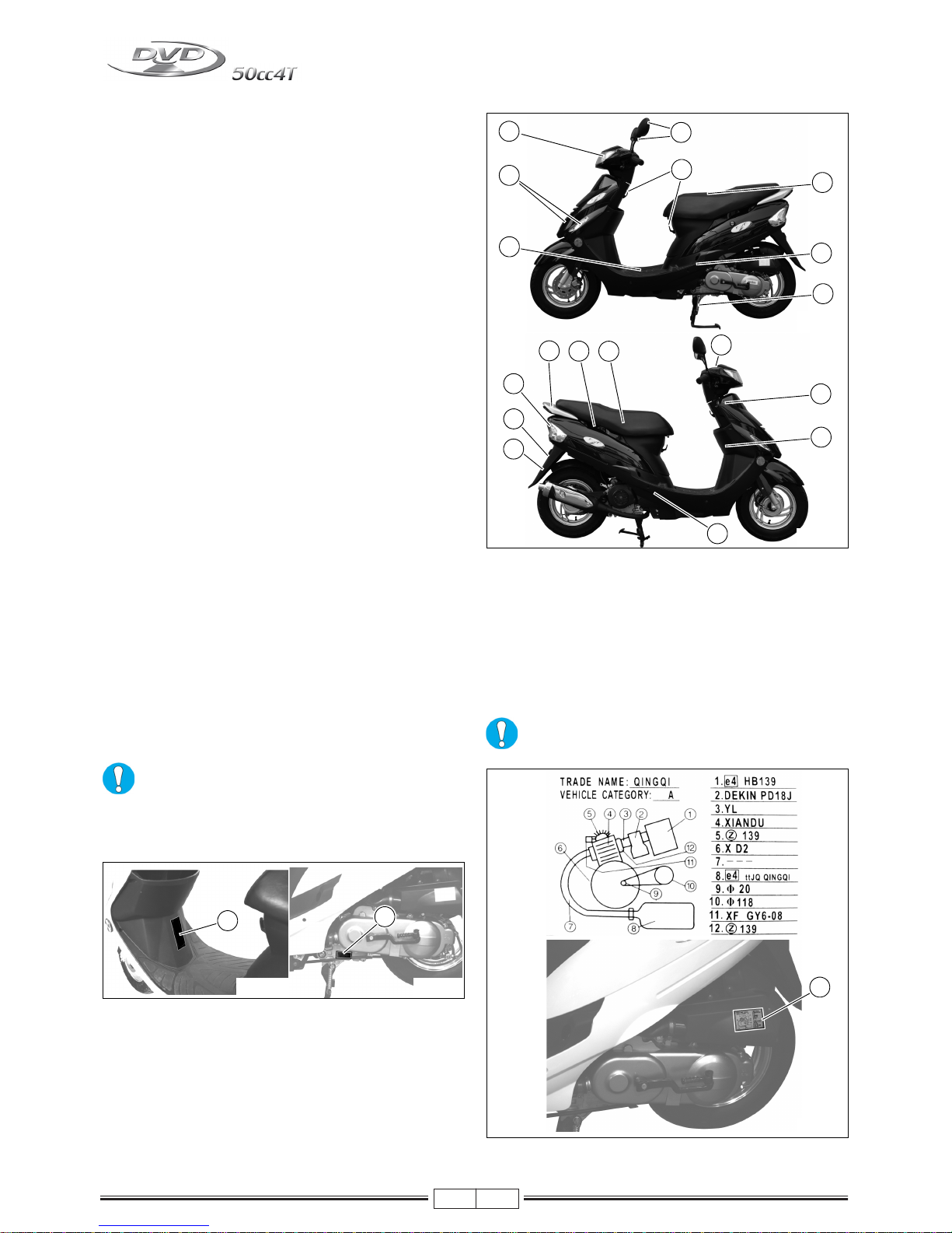
IDENTIFICATION DATA: CHASSIS N° /
ENGINE N°
- The type approval and vehicle numbers (VIN) are
stamped on the vehicle’s chassis in the positions
shown in the photos (A-Fig. 04).
- Engine identification data are visible on the left engine
crankcase (B-Fig. 05).
Altering identification data will be punished according to the law.
- When ordering spare parts, also quote the vehicle
identification data.
ANTI-TAMPERING PLATE
An anti-tampering plate (C-Fig. 06), bearing all vehicle
identification data required by Directive 97/24/CE
Chap. 7, is fitted on the filter box. If you have the filter box
replaced, make sure the plate is fitted too.
This label must be neither removed nor
changed.
10
13
1
2
5
6
3
4
11
12
14
7
8
9
17
16 15
3
Fig. 03
Fig. 02
A
B
Fig. 05Fig. 04
C
Fig. 06
Page 8
03/10
4
TIRES
Type: Tubeless (without inner tube)
It is possible to use tires with load-capacity and
speed indexes that are higher than or identical
to those indicated.
It is however necessary for the speed indexes
to be identical for both tires.
USE ONLY HOMOLOGATED TIRES.
Check the tire conditions (before every journey): if they
are broken (cracked) or cut, have them replaced as soon
as possible.
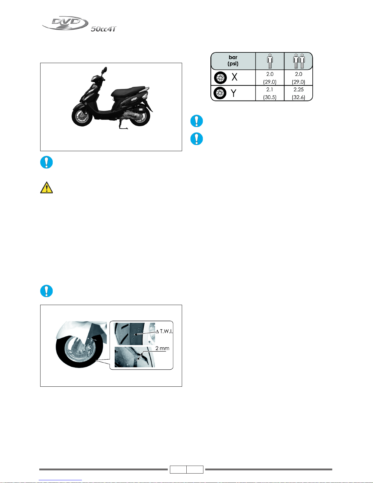
“T.W.I.” marks are provided all around the tire side walls.
These correspond to tire wear indicators, which are situated in the tire’s tread; if there is no difference between
the thickness of these indicators and the tread depth itself, the tire must be replaced.
Minimum tread depth (front and rear) is 2 mm
(Fig. 08).
PRESSURE
The pressure of tires must be adjusted while
the tire is at ambient temperature.
Pressure differing from that indicated can lead
to higher fuel consumption, irregular wear of
the tire, impaired vehicle performance and riding conditions.
X
3.50-10 42J
Y
3.50-10 42J
Fig. 07
Fig. 08
Page 9
03/10
5
FUEL TANK
To gain access to the fuel tank, proceed as follows:
- Place the vehicle on the centre stand.
- Take the ignition key out of the ignition barrel and insert it into the lock on the left hand side of the seat (A-
Fig. 09).
- Open seat by turning ignition key clockwise (Fig. 10).
- Remove the cap (B-Fig. 09) and fill the tank.
- After refuelling, immediately remove any possible traces of fuel from the vehicle body, since fuel may deteriorate the vehicle’s outer surfaces.
- The quantity of fuel, as well as a low fuel level, are displayed by the corresponding indicator on the right
hand side of the instrument board (5-Fig. 16).
- Use UNLEADED PETROL.
Important: do not overfill the fuel tank. Overflowing fuel may damage the vehicle.
Petrol is extremely inflammable; avoid approaching the fuel filler - also during filling with lit cigarettes or naked flames (for instance
matches). Danger of fire!
*Indicative value in litres
FRONT LUGGAGE COMPARTMENT
This is located at the centre of the lower fairing (AFig. 11). It can be used for storage small and light ob-
jects.
It is advisable not to leave any documents or
valuables inside these compartments.
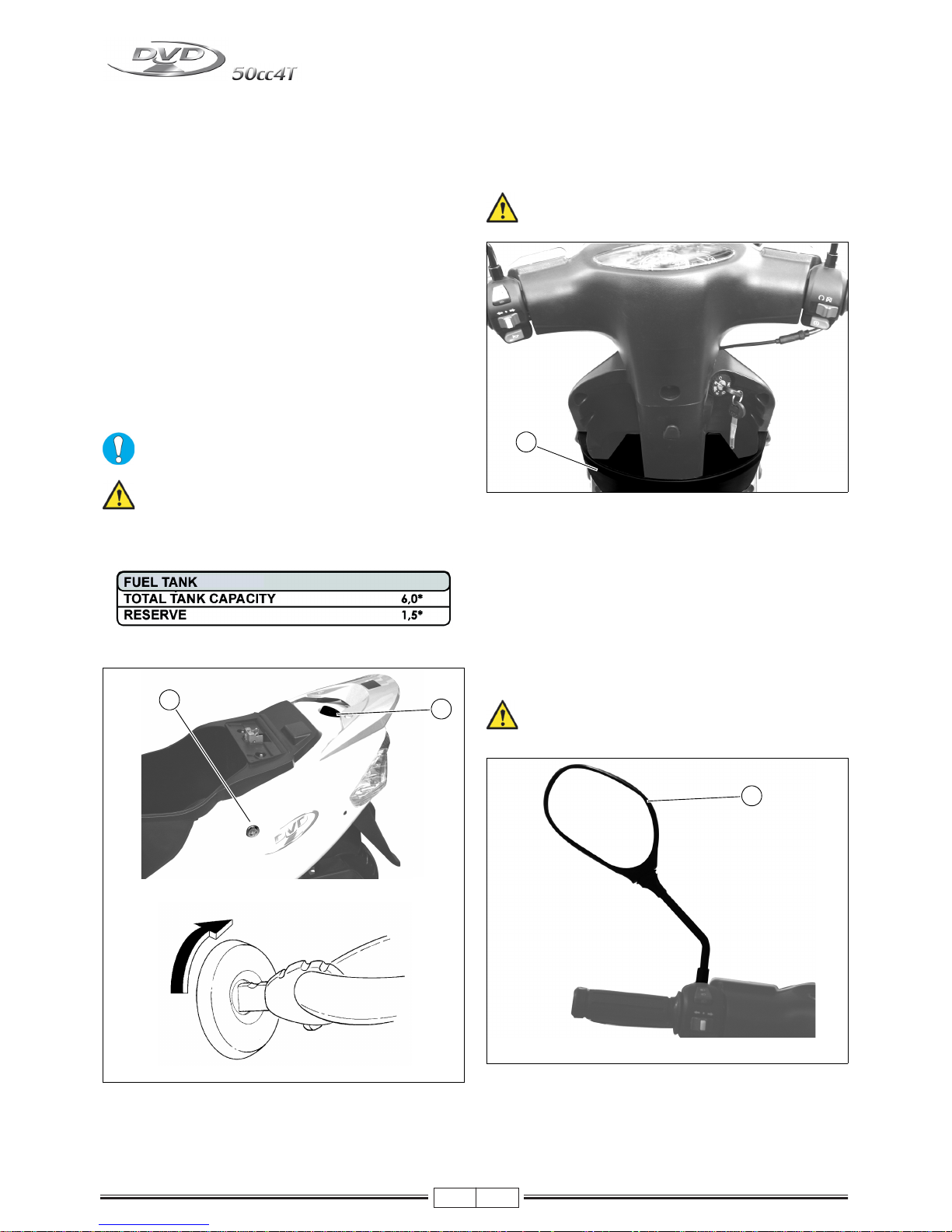
REAR-VIEW MIRROR
The left hand rear view mirror must be fitted to the handlebar, in its special seat and firmly secured in place.
Adjust the visual angle of the mirror, while you are sat in
riding position on the vehicle in riding order, by turning
the mirror until you obtain the best conditions of visibility
(P-Fig. 12).
Objects that are visible in the mirror are actually closer
than they seem.
Do not adjust rear-view mirror while driving. Always wait to stop at a traffic light, for example.
A
B
Fig. 10
Fig. 09
A
Fig. 11
P
Fig. 12
Page 10
03/10
6
HELMET COMPARTMENT
- This is located under the seat. The helmet compartment can contain a Jet helmet. Some types of helmet
may not fit into the compartment. Before purchasing
your helmet, make sure it fits into the compartment.
- To gain access to the helmet compartment, put the vehicle on its stand; take the ignition key out of the switch
block and insert it into the lock on the left hand side of
the seat (Fig. 13).
The helmet compartment can be used to carry
light objects. They shall be stored in such a
way as not to compromise the vehicle’s stability while riding. Do not store objects which are
not temperature resistant (lighters, inflammable liquids, perishable goods, etc.). Do not
leave documents or valuables inside the helmet compartment.
LUGGAGE HOOK
The vehicle is fitted with two luggage hooks (G-Fig. 15)
on which you can hang small objects or bags. One of the
hooks is located at the centre of the lower fairing, the other is in centre position, under the seat. They must be
used only for holding light and stable loads.
Never use these hooks for loads that alter your
riding position or put the vehicle’s stability at
risk. The load must never protrude from the
sides of the vehicle.
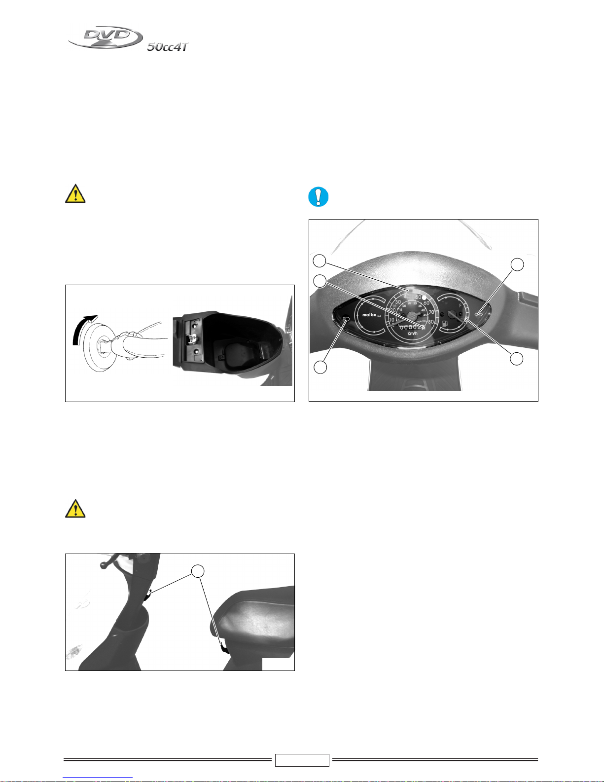
INSTRUMENT BOARD
1- Analogue instruments, Speedometer
This indicates the current speed in kmh or mph.
2- Odometer
This indicates the total distance travelled in km.
3 - Green turn indicator light
4 - Blue high beam indicator light
5- Fuel level indicator
This displays the level of fuel in the tank.
Red zone: reserve - REFUEL!!
To prevent damage, avoid washing instruments with pressurised system.
Fig. 14Fig. 13
G
Fig. 15
3
5
1
2
4
Fig. 16
Page 11

03/10
7
HANDLEBAR CONTROLS
RIGHT HAND CONTROL (FIG. 17)
1) Throttle grip
2) Front brake lever
3) Engine stop:
right = Position - Engine stop
left = Position - Engine starting
4) Electric starter button.
LEFT HAND CONTROL (FIG. 18)
1) Rear brake lever
2) Horn button.
3) Turn indicator switch.
4) Button for turning off indicator lights
5) Light switch:
high beam
low beam
PASSING High beam “flash” lever
CHECKS BEFORE USE
4
1
2
3
Fig. 17
1
5
4
2
3
Fig. 18
Part Check
Fuel Enough fuel
Transmission oil - Engine oil Level within limits specified. Check for leaks
Tires Check pressure/wear/damage
Nuts, screws, bolts Check tightness
Steering Free movement from one end to the other
Front/Rear brakes Working properly and not worn; if necessary, adjust or replace
Throttle Operation should be smooth, if necessary lubricate or adjust
Lights and indicators Proper working conditions
Stand Operation of stand and return springs
Loads
Make sure loads and accessories (e.g. rear case) are firmly secured to
vehicle
Page 12

03/10
8
MAINTENANCE TABLE
NOTE - Maintenance operations should be performed more frequently if the vehicle is used in rainy weather, in dusty
places or on rough terrain.
Due to their simplicity, checks featuring an asterisk CAN also be carried out by technicians not authorised by MALBO Line or MALAGUTI, but under their direct responsibility.
TRANSMISSION OIL
Checking level/topping up every 5,000 km/3,120
miles or 12 months
1 - Park the vehicle on a level surface on its centre
stand.
2 - Unscrew the dipstick (A-Fig. 19)
3 - If necessary, top up until it overflows.
4 - Refit and tighten the oil filling screw. Recommended
oil: Q8 T35 - 80W
Renew after the first 500/1,000 km (312/624 mi) and
every 10,000 km (6,240 mi) or 24 months
1 - Park the vehicle on a level surface on its centre
stand.
2 - Put a container under the drain cap.
3 - Remove the oil filler screw (A-Fig. 19).
4 - Unscrew the oil drainage screw (B-Fig. 19) and
drain out the entire oil content.
5 - Clean the drainage screw and refit it.
6 - Fill with new oil of the recommended type until you
notice oil overflowing.
Recommended oil: Q8 T35 - 80W
Capacity: 120 cc.
7 - Refit the oil filler screw and wrench in place.
Perform this operation with the engine off and
cold.
Prevent foreign matters from getting into transmission crankcase during checks or oil changes. Prevent oil dripping on tires or wheels.
A
B
Fig. 19
Page 13
03/10
9
ENGINE OIL
Check oil level EVERY 500 KM (310 MILES)
As far as four-stroke engines are concerned, engine oil is
used to lubricate distribution components, base bearings
and the thermal unit. An insufficient oil quantity or use
a poor quality oil can seriously damage the engine.
In all four-stroke engines, deterioration of the oil and a
certain consumption are to be considered normal. Consumption, in particular, strictly relates to conditions of usage (oil consumption increases if the vehicle is used with
the throttle fully open).
To prevent trouble, check the oil level more frequently with respect to the indications given in the MAINTENANCE TABLE, especially before long journeys.
Checking the oil level
This check should be performed when the engine is cold,
as described below:
1 - Park the vehicle on flat ground and put it on its cen-
tre stand.
2 - Stop the engine and wait a few minutes for the oil to
stabilise.
3 - Unscrew the cap/dipstick (A-Fig. 20), dry it with a
clean cloth and refit it, without wrenching it
.
4 - Remove the cap/dipstick and make sure the level
falls between the MAX and MIN notches; if neces-
sary, top up with Q8 CLASS 10W40 oil.
5 - Refit the cap/dipstick (A-Fig. 20).
When checking the oil level, make sure the vehicle is upright; slight tilting may alter the readings.
If you need to check the level when the engine
is warm, remember that the level line will be
lower. It is best to wait at least 10 minutes from
stopping the engine in order to have a correct
reading
Topping up
Before topping up, check the oil level and in no case
allow the level to rise above the MAX notch.
Never allow the level to rise above the MAX
mark! Excessive internal pressure can impair
performance and cause malfunctioning or
damage to the engine.
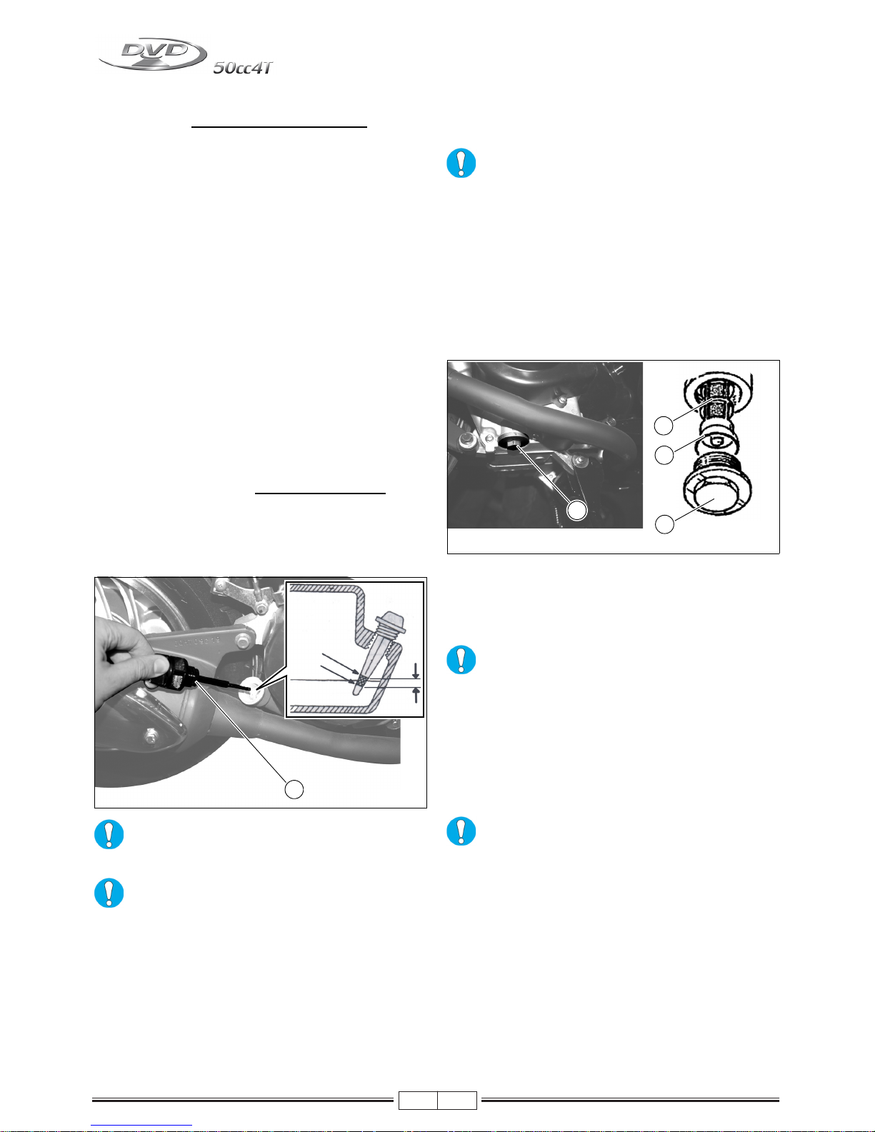
Change engine oil and clean the filtering net every
2,500 km/1,560 miles or 6 months
1 - Warm the engine up for a few minutes.
2 - Stop the engine and put an oil container under the
engine.
3 - Remove the drainage plug of the filtering net (A-
Fig. 21-22) and the dipstick, then let oil flow out.
4 - Clean the filtering net (C-Fig. 22) with a suitable
solvent and blow dry with compressed air.
5 - Refit the filtering net, a new O-ring (B-Fig. 22) and
the drain cap.
Make sure the O-ring is correctly seated.
6 - Tighten the drain cap at the requested torque set-
ting: Tightening torque: 25-28 Nm/2.5-2.8 kgm
7 - Fill the engine with 800 cc of Q8 CLASS 10W40 oil
and top up if necessary. Refit the dipstick.
8 - Run the engine and let it warm up; check for any
leaks. If leaks are noted, stop the engine and locate
their cause.
Letting the engine run with an insufficient
amount of lubricant or with the wrong types of
lubricant causes wear to moving parts and can
in the long run cause serious damage.
A
Max
Min
Fig. 20
A
C
B
A
Fig. 22Fig. 21
Page 14

03/10
10
LUBRICANT TABLE
NOTE - The vehicle’s life depends also on the care devoted to lubricating it.
SPARK PLUG
Replace every 5,000 km (3,120 mi)
The spark plug is an essential component:
1 - Proper care of the plug is important for maintaining
the engine in perfect working order.
2 - For maintenance, remove the centre partition under
the seat (P-Fig. 23) , by unscrewing the three fixing
screws (V-Fig. 24) (2 on the footboard and one
inside the helmet compartment) and raising the bot-
tom profile (with the aid of a screwdriver) sealed
onto the two teeth of the footboard. Carefully
remove the cap by turning it clockwise and anti-
clockwise alternatively (C-Fig. 24); now, unscrew
the spark plug using the special wrench supplied
with the vehicle (all operations on the spark plug
must be performed when the engine is cold).
3 - Examine the spark plug conditions after a reasona-
bly long drive (10-15 km) and after letting the
engine cool down (at least 10-15 minutes), since
the sediments and the colour of the insulator can
provide useful information about the heat rating of
the spark plug, carburetion, lubrication and general
conditions of the engine. A light brown colour of the
insulator, around the central electrode, indicates
good working order.
4 - After disassembling the spark plug, suitably clean
the electrodes and the insulator using a metal
brush. Adjust the electrode gap using a filler gauge:
the gap should range from 0,5 ÷ 0,6 mm.
5 - Blow onto it so as to prevent possible residues from
entering the engine, then refit it, by wrenching until
finger tight. Then, using the special spark plug
wrench, wrench it to the recommended torque
wrench setting: 17.5 Nm / 1.75 kgm.
Spark plugs with a heat rating differing from
the recommended one may seriously damage
the engine.
It is imperative that any spark plug exhibiting
cracks on the insulator or corroded electrodes
be replaced.
THROTTLE FREE PLAY ADJUSTMENT
Check that the throttle grip idle stroke is 1-3 mm (measured on the end of the throttle grip).
0,5в0,
Fig. 24Fig. 23
V
P
C
Page 15
03/10
11
CHECKING THE PADS AND DISC OF THE
FRONT BRAKE (CONDITION AND WEAR)
1 - We recommend you to check the front pads and disc
every 2,500 km (1,560 mi).
2 - The minimum thickness of the brake lining shall not
be less than 2 mm (Fig. 25). Check the thickness of
the brake pads as illustrated in Fig. 26.
3 - If the thickness of the pads is close to the lowest per-
mitted limit or if they are damaged, have them
replaced immediately.
CHECKING THE REAR BRAKE
- Check whether the lever’s stroke is as illustrated in
Fig. 27. The idle stroke of the lever is approximately 10
mm.
- To adjust the rear brake, turn the adjuster under the en-
gine, as illustrated in Fig. 28.
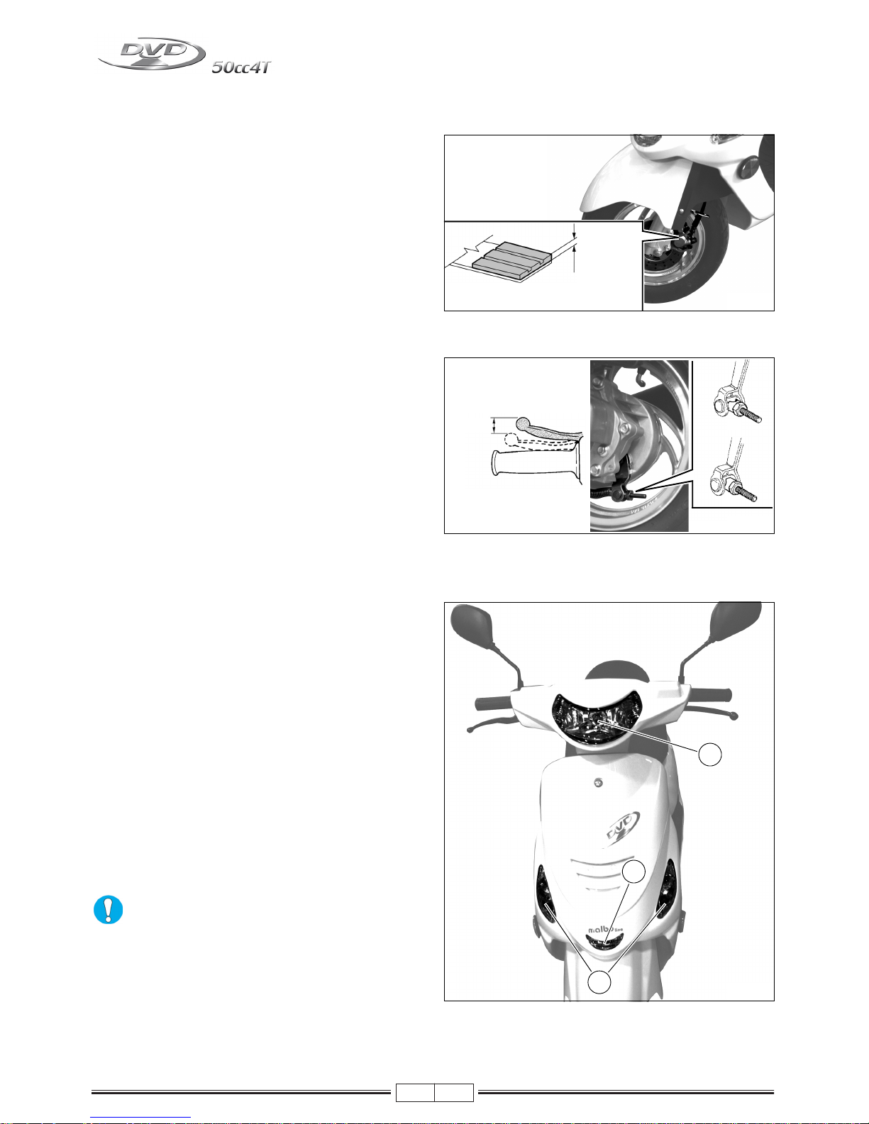
HEADLIGHT
To increase visibility at night, quartz (halogen) type headlights are fitted.
- Low beam / high beam (A-Fig. 29)
Bulb 12V - 25/25W
- Parking light bulb (B-Fig. 29)
Bulb 12V - 5W
NOTE - We advise you to check if the replaced bulb works
properly before refitting the headlight unit definitively.
FRONT TURN INDICATOR
- Front turn indicator (C-Fig. 29)
Orange lamp 12V - 10W
The rate at which the turn indicator warning light
on the instrument board flashes will increase to
signal that one of the four indicators is not working.
MIN. 2mm
Fig. 26Fig. 25
Fig. 28Fig. 27
NO
OK
10 mm
Fig. 29
B
A
C
Page 16
03/10
12
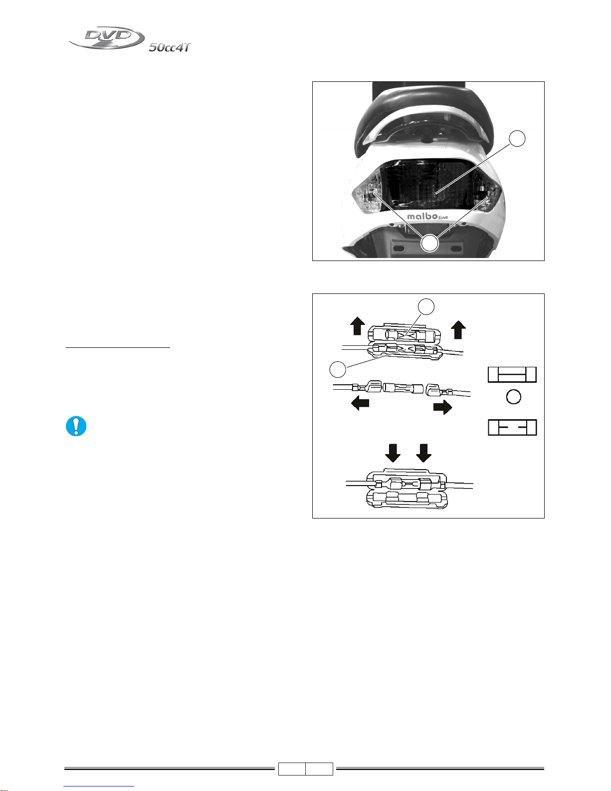
TAIL LAMP (WITH STOP LIGHT)
- Parking/Stop light (B-Fig. 30)
Bulb 12V - 21W/5W
- Rear turn indicator (E-Fig. 30)
Bulb 12V - 10W (R10W)
NOTE - Visually check if the stop light works properly, by
pulling one of the two brake levers.
FUSES
The electrical equipment includes a fuse protecting the
main components against faults. It is located close to the
battery (F-Fig. 31).
REPLACING THE FUSE
To replace the fuse, just open the battery compartment, extract the blown fuse and replace it with one of the same capacity. Inside the fuse box, you will find a spare fuse (S-
Fig. 31). Check that the fuse you are using has the same
amperage of the fuse you are replacing.
Do not replace the fuse with one having a higher
capacity, as it could seriously damage the electrical equipment and cause a fire on the vehicle in
the event of a short circuit.
Fig. 30
B
E
Fig. 31
F
S
Page 17
03/10
13
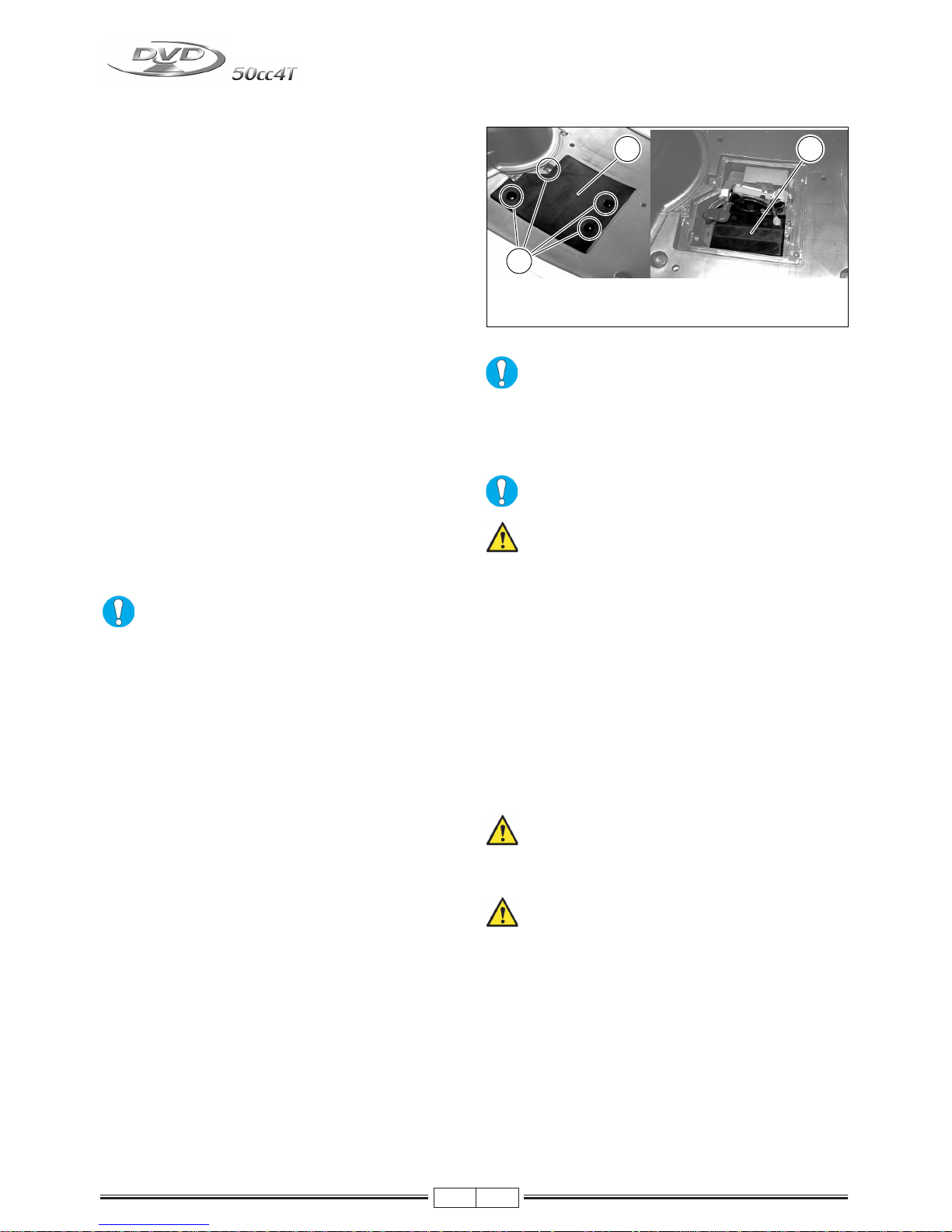
Battery (12V - 5Ar)
The battery compartment is located in the front section of
the vehicle.
Fitting battery
(operation performed before delivery)
To fit battery, proceed as follows:
- Take a previously charged battery.
- Remove the rubber mat.
- Loosen the four screws (V-Fig. 32) and remove the battery cover (C-Fig. 33).
- Remove the 10A general protection fuse.
- Insert the battery (B-Fig. 33) and make sure it is correctly seated.
- Connect the battery wiring:
- positive pole (+) to the RED - RED/BLUE cables
- negative pole (-) to the BLACK cables.
- Wrench down the battery terminals.
- Refit the 10A general protection fuse previously removed.
- Check that the battery and the wiring harness are correctly installed.
- Refit the battery cover and the rubber mat.
NEVER invert the cable connections.
Do not use the vehicle if the battery has not
been fitted correctly and connected to its cables.
This may cause failures and short circuit of the electrical
system and its components.
If the battery remains flat it will be seriously
damaged.
We advise you to use protective gloves and
goggles while removing the battery from its
compartment, for example to recharge the battery.
BATTERY RECHARGING
- To perform this operation, it is recommended to take
the battery out of its compartment.
- Disconnect the cables.
- It is good practice to recharge with amperage of 1/10
with respect to that of the charged battery.
- Refit the battery, being careful to connect the positive
cable (red) to the + pole and the negative cable (black)
to the - pole.
- Wrench down the battery terminals.
- The battery must always be kept completely charged.
During winter or when the vehicle is not used, charge
the battery at least once a month.
Danger of explosion! Never use open flames
(lighters, matches, etc.) to check the battery liquid level.
The battery contains sulphuric acid, which is
highly toxic. Avoid any contact with eyes, skin
or clothes.
Fig. 33Fig. 32
BC
V
Page 18
03/10
14
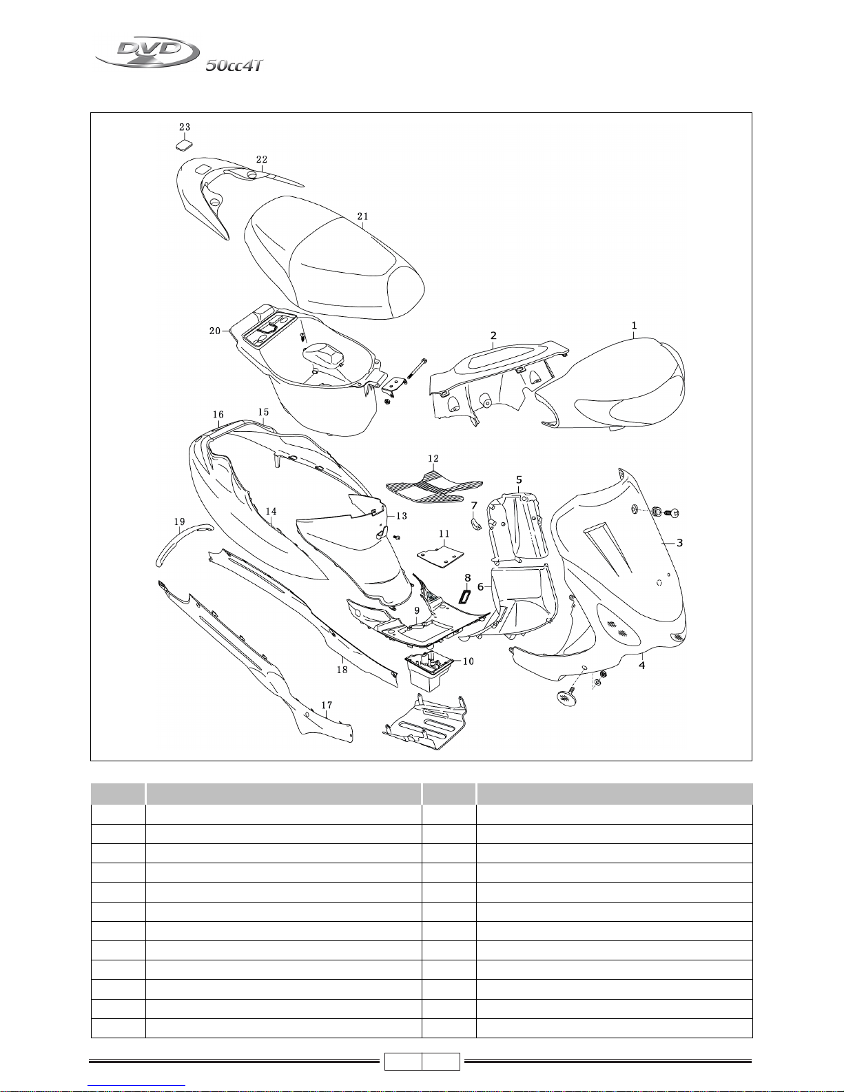
FAIRING
Fig. 01
Nr. Item Nr. Item
1 Handlebar cover (front) 14 Rear fairing r/h
2 Handlebar cover (rear) 15 Rear fairing l/h
3 Front shield 16 Central fairing
4 Shield (lower) 17 Side cover r/h
5 Inner shield (upper) 18 Side cover l/h
6 Inner shield (lower) 19 Central fairing
8 VIN number cover 20 Helmet compartment
9 Foot board panel 21 Seat
10 Battery box 22 Rear handle
11 Battery cover 23 Plug
12 Mat set
13 Side cover mounting
Page 19
03/10
15
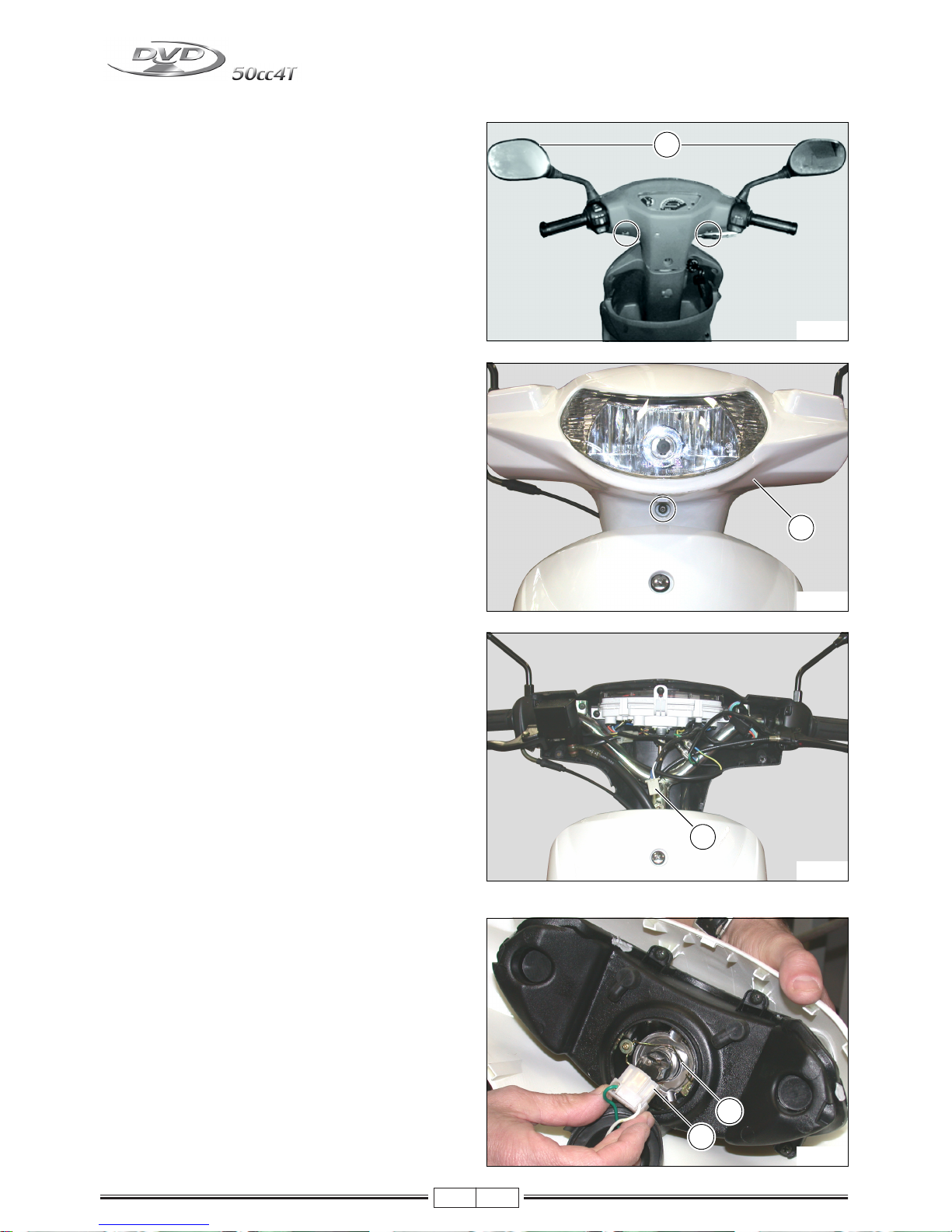
DISMANTLING THE FRONT HANDLEBAR COVER
- Remove the RIGHT and LEFT mirrors (1)
- Remove the front handlebar cover (2).
- Disconnect the connector (3).
REPLACING THE HEAD LIGHT BULB
- Disconnect the connector (1) and replace the light
bulb (2).
1
Fig. 02
2
Fig. 03
3
Fig. 04
1
2
Fig. 05
Page 20
03/10
16
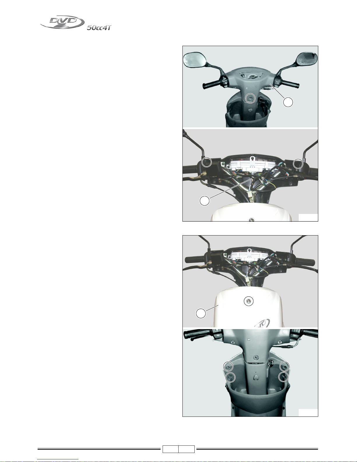
DISMANTLING THE REAR HANDLEBAR COVER
- Remove the rear handlebar cover (1).
- Remove the speedometer cable (2).
DISMANTLING THE FRONT SHIELD
- Remove the front shield (3).
2
1
Fig. 06
3
Fig. 07
Page 21
03/10
17
DISMANTLING THE SIDE COVERS
- Remove the central fairing (1).
- Remove the right and left side covers (2).
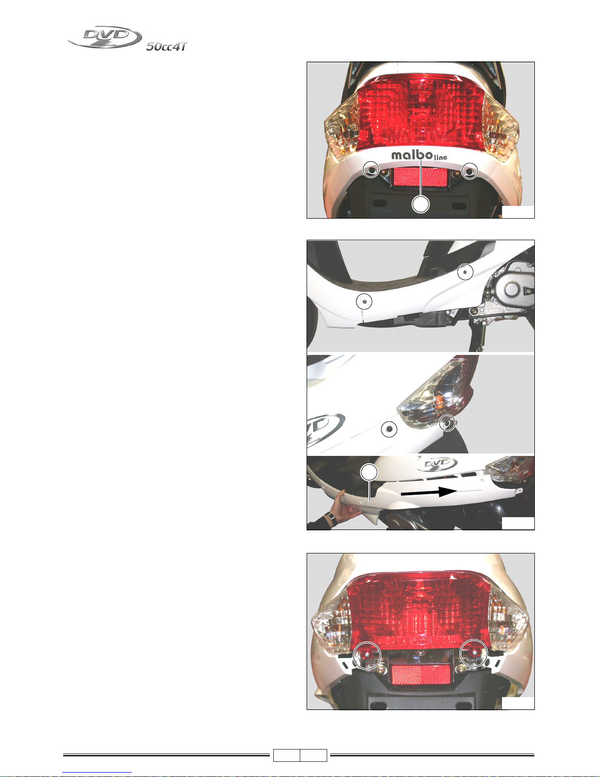
DISMANTLING THE TAIL LIGHT ASSY
- Unscrew the tail glass screws.
1
Fig. 08
2
Fig. 09
Fig. 10
Page 22
03/10
18
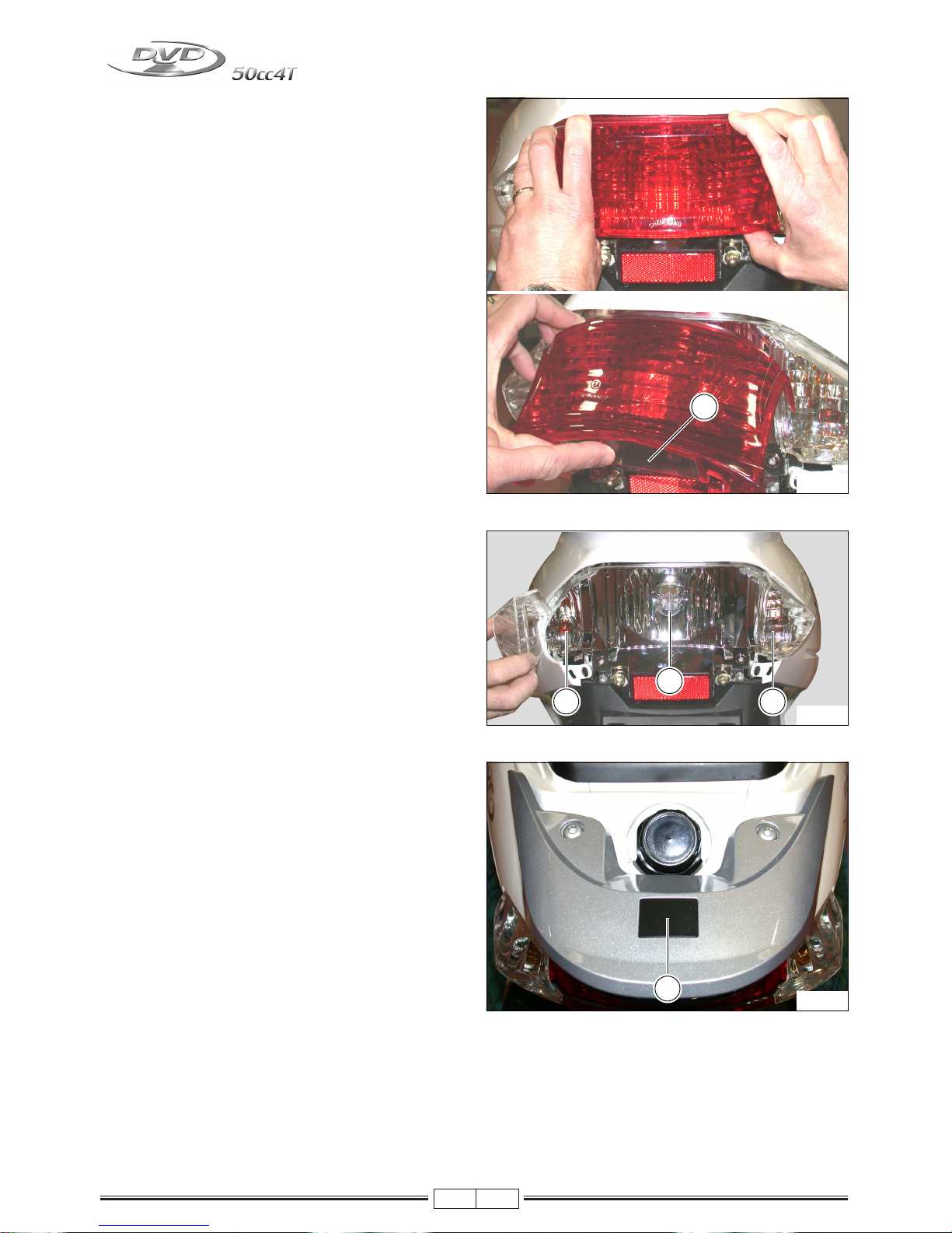
- Release the tail cover glass by slighting pushing your
thumbs on the illustrated points.
NOTE - Be careful not to push too hard on the point (1); the
glass could break.
- Tail light bulb (2).
- Turn indicator light bulbs (3).
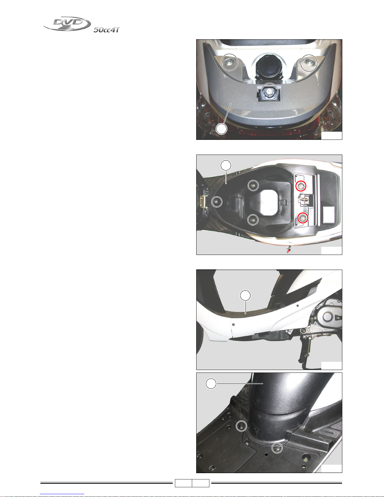
DISMANTLING THE REAR HANDLE
- Remove the plug (1).
1
Fig. 11
2
3
3
Fig. 12
1
Fig. 13
Page 23
03/10
19
- Remove the rear handle (2).
DISMANTLING THE HELMET COMPARTMENT
- Open the seat.
- Unscrew the illustrated screws and nuts.
- Remove the helmet compartment (1).
DISMANTLING THE FAIRING
- Remove the mat set (1).
- Remove the side cover mounting (2).
2
Fig. 14
1
Fig. 15
1
Fig. 16
2
Fig. 17
Page 24
03/10
20
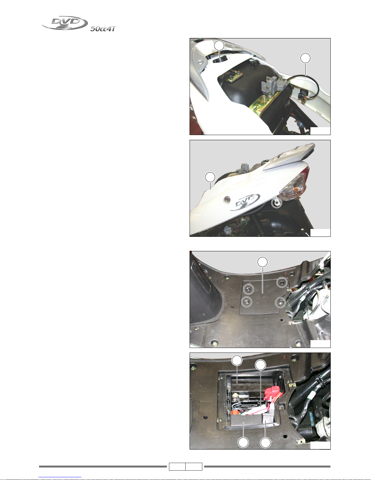
- Unscrew the fuel tank cap (3).
- Before removing the fairing, release the seat opening
cable (4).
- Remove the fairing (5).
BATTERY BOX
- Remove the battery cover (1).
- Remove the battery (2).
- Remove the 10 Ampere fuse box holder (3).
- Remove the CDI unit (4).
- Remove the starter relay (5).
4
3
Fig. 18
5
Fig. 19
1
Fig. 20
2
4
5
3
Fig. 21
Page 25

03/10
21
DISMANTLING THE FOOT BOARD
- Remove the battery (see specific chapter).
- Remove the foot board (1).
DISMANTLING THE LOWER SHIELD AND INNER SHIELD
- Remove the ignition barrel cover (1).
- Remove the bag handle hook (2).
- Remove the screws and remove the inner shield (3) and
lower shield (4).
NOTE - Before removing the lower shield (4), remove the
front wheel and front mudguard as indicated in the
specific chapters.
1
Fig. 22
1
Fig. 23
2
3
4
Fig. 24
Page 26

03/10
22
REPLACING THE PARK LIGHT AND TURN INDICATORS BULBS
- Pack light bulb (1).
- Turn indicator light bulb (2).
DISMANTLING THE FRONT MUDGUARD
- Release the two front mudguard halves (wheel side and
shield side).
- Remove the wheel as indicated in the specific chapter.
- Release the two mudguard halves (wheel and shield
sides) from the bracket (1).
1
2
Fig. 25
Fig. 26
1
Fig. 27
Page 27

03/10
23
- Remove the rear part (2) and front part (3).
2
3
Fig. 28
Page 28

03/10
24
FRONT WHEEL
Fig. 29
Nr. Item Nr. Item
1 Front rim 7 Brake disc
2 Front tyre (Tubeless) 8 Bolt M8x24
3 Spacer 9 Spacer front brake
4 Bearing 6002 (ø15x32x9) 10 Nut M12
5 Bearing 6003 (ø17x35x10) 11 Front wheel spindle
6 Oil seal 12 Speedo drive
Page 29

03/10
25
DISMANTLING THE FRONT WHEEL
Check perfect vehicle stability, positioned on the
main stand.
- Disconnect the speedometer cable (2).
- Unscrew the nut (1).
DISMANTLING THE FRONT BRAKE CALLIPER
- Unscrew the front brake calliper screws (3).
- Lift the vehicle using the lift and remove the wheel.
DISMANTLING THE BRAKE DISC
- Unscrew the 3 illustrated screws and remove the brake
disc.
1
Cs - N*m
53
2
1
Fig. 30
3
Cs - N*m
26
3
Fig. 31
V3
Cs - N*m
23
Fig. 32
Page 30

03/10
26
FRONT RIM CHECK (WHEEL REMOVED)
Check front rim oscillation (Radial and Axial) and make
sure it does not exceed the service limit. If oscillation was
caused by the bearing, the rim may be reused after replacing the bearing. Otherwise, replace with a new rim.
Oscillation limit = 2.0 mm
CHECKING THE FRONT WHEEL SPINDLE
Check front shaft oscillation with a centesimal gauge and
replace it if it exceeds the service limit.
Measurement instrument: Micrometer
Linearity limit: 0,25 mm
DISMANTLING THE BRAKE PAD SET
Do not pull the brake lever before installing the pad
set.
- Remove the screw (4).
- Rotate the calliper away from the cover.
- Remove the calliper cover.
Fig. 33
Fig. 34
4
Cs - N*m
26
4
Fig. 35
Page 31

03/10
27
When reassembling:
- Mount the springs (5) as indicated.
- Mount the pad set (6) facing them in the indicated directions (flat side (7) facing towards the cover).
When reassembling the pad set, fully push the
piston into its housing.
After reassembling, pull the brake lever several
times to position the pad set in contact with the
brake disk.
5
6
7
Fig. 36
Page 32

03/10
28
FRONT FORK
Grease parts Nr. 8, 9, 10, 11, 12, 13, 26.
Tighten parts Nr. N. 3, 4, 15, 17, 29 to the specified tightening torque.
Fig. 37
Nr. Item Nr. Item
1 Handlebar 17 Plug
2 Bolt 18 O-Ring
3 Nut 19 Spring
4 Bolt 20 Piston tube
5 Screw 21 Seeger
6 Lock nut 22 Return spring
7 Lock washer 23 Fork tube
8 Adjustable cone 24 Dust seal
9 Steering ball cages N° 26 (ø 5/32) 25 Seeger
10 Upper washer 26 Oil seal
11 Lower washer 27 R/h fork leg assy
12 Steering ball cages (lower) N° 29 (ø 5/32) 28 Copper washer
13 Steering cone 29 Screw
14 Bottom yoke
15 Screw
16 L/h fork leg assy
Page 33

03/10
29
DISMANTLING THE FORK
- Remove the handlebar cover.
- Unscrew screw (1) and screw (2).
- Remove the front wheel.
- Remove the front mudguard.
- Remove the calliper.
- Remove the front shield
- Slide the handlebar off the fork tube.
- Unscrew the steering lock nut (3).
- Slide off the lock washer (4).
- Unscrew the adjustable cone (5).
- Slide out the fork, being careful of ball cages.
REPLACING CAPS AND STEERING CONES
- Using a wrench, remove the steering caps.
- Using a chisel, slide off the steering cone (6).
Fig. 38
1
2
4
3
5
Fig. 39
6
Fig. 40
Page 34

03/10
30
Install the following new parts:
- Fork cone (7).
- Steering caps (8).
DISMANTLING THE FORK
- Lubricate the caps
- Install 26 ball cages (9) for the upper cap and 29 ball
cages (10) for the lower cap (ø 5/32).
- Insert the fork in the steering shaft.
- Install and tighten the adjustable cone (11).
- Loosen and re-tighten the adjustable cone.
- Position the lock washer (12).
- Install and tighten the steering lock nut (13).
OIL LEVEL CHECK
- Insert a stick or gauge and check that oil is 110 ±5 mm
from the upper edge of the rod (move the rod to end
stop).
If necessary, top up with oil: Q8 FORK OIL
8
7
Fig. 41
13
Cs - N*m
30
11
13
9
12
10
Fig. 42
Quantity per tube ~ 40 cc
Fig. 43
Page 35

03/10
31
MAIN IGNITION SWITCH
- Remove the front shield.
- Unscrew the fixing screws.
- Disconnect the connector.
- Remove the key switch (1).
REAR WHEEL AND SHOCK ABSORBER
1
Fig. 44
Fig. 45
Nr. Item Nr. Item
1 Rear rim 8 Nut M6
2 Rear tire 9 Washer
3 Brake shoes 10 Wheel nut
4 Spring 11 Shock absorber
5 Cam 12 Bolt M10x71
6 Brake lever 13 Nut
7 Bolt M6 x 28 14 Bolt M8x24
Page 36

03/10
32
DISMANTLING THE REAR WHEEL
- Remove the exhaust.
- Unscrew the nut (D).
- Remove the rear wheel.
DISMANTLING THE BRAKE SHOES
- Remove the rear wheel.
- Unscrew the screw (V).
- Remove the brake shoes (1) being careful not to damage the springs (M).
DISMANTLING THE SHOCK ABSORBER
- Remove the rear fairing.
- Remove the air filter.
- Unscrew the screws (V
2).
- Remove the rear shock absorber.
D
Cs - N*m
120
Fig. 46
D
1
Fig. 47
V
M
V2
Cs - N*m
29
Fig. 48
V2
Page 37

03/10
33
CHECKING THE BRAKE HUB
Check the INTERNAL DIAMETER of the brake hub and replace the rim if the INTERNAL DIAMETER exceeds wear
limits.
Wear limit: 120.7 mm
CHECKING BRAKE SHOES
Make sure brake shoes are not worn or damaged and replace the complete brake shoe set if necessary.
CHECKING THE SHOCK ABSORBER
Make sure the shock absorber does not leak and that it is
not damaged. Replace if necessary.
Fig. 49
Fig. 50
Fig. 51
Page 38

03/10
34
DISMANTLING THE MAIN STAND
Secure the vehicle so that it does not fall when the
main stand is removed.
- Remove the split pin (1).
- Remove the spring (2).
- Slide out the pin (3) and remove the main stand.
REMOVING THE ENGINE FROM THE CHASSIS
- Remove the helmet compartment (1).
1
Fig. 52
3
2
Fig. 53
1
Fig. 54
Page 39

03/10
35
- Remove the right and left side covers (2).
- Disconnect the carburettor starter connector (A) and
stator connector (B).
- Release the throttle cable (3), the fuel hose (4) and depression hose (5).
- Unscrew the filter box clamp (6).
2
Fig. 55
Fig. 56
A
B
5
4
6
3
Fig. 57
Page 40

03/10
36
- Disconnect the positive and negative starter motor cables (7).
- Remove the rear brake cable adjustment nut (8).
- Remove the filter case (9).
- Unscrew the rear shock absorber screw (10).
7
Fig. 58
8
Fig. 59
9
Fig. 60
10
Fig. 61
Page 41

03/10
37
- Slide off the spark plug cap (11).
- Remove the main stand (see specific chapter).
- Unscrew the nut (12), slide off the engine pin and remove the engine from the frame.
- Unscrew the screws (13).
- Unscrew the exhaust manifold screws (14) and remove
the exhaust.
11
Fig. 62
12
Fig. 63
13
Cs - N*m
24
13
13
Fig. 64
14
Cs - N*m
10
14
14
Fig. 65
Page 42

03/10
38
- Unscrew the nut (15) and remove the rear wheel.
15
Fig. 66
Page 43

03/10
39
CHECKING THE END COMPRESSION PRESSURE
- With the engine cold, remove the spark plug cap
- Remove the spark plug.
- Fit a compression testing pressure gauge in the spark plug seat with a spark plug fitting and tighten it.
- Run the engine using the starter motor and with the carburettor fully open, until the reading on the pressure gauge
is stable.
- If the pressure is normal, remove the device and reassemble the dismantled parts.
- If the pressure readings are below those indicated, check the rpm used for the test, if it is low, check the starter
system. If the number of rpm is perfect or slightly above, make sure the correct seal has been chosen for the cylinder base and check the seals of the thermal part ( elastic bands- valves etc...)
IF YOU HAVE A HARD TIME INSERTING THE PRESSURE GAUGE FITTING, DISCONNECT THE ENGINESWING ARM CONNECTION PIN AND PULL BACK THE ENGINE AS REQUIRED TO INSERT THE FITTING.
Technical specifications
Spark plug fitting
10 mm
Rpm
~ 800 rpm (starting speed).
Compression end pressure
14 ÷ 15 BAR
Page 44

03/10
40
ENGINE DISMANTLING
- Place the engine on a suitable support.
- Unscrew the engine oil tank cap (1).
- Unscrew the cap (2) and drain oil.
Note: the filtering net (3) must be cleaned and the
gasket replaced at each oil change.
DISMANTLING THE CLUTCH COVER
- Unscrew the 8 cover fixing screws.
- Remove the clutch cover.
- Remove the gasket.
- Remove the 2 bushes.
Replace the gasket each time the cover is dismantled.
2
Cs - N*m
20
Fig. 01
Fig. 02
V8
Cs - N*m
10
Fig. 03
Page 45

03/10
41
DISMANTLING THE PRIMARY PULLEY ASSY
- Unscrew the nut (1) and remove the washer (2).
- Remove the kick starter plate (3).
- Remove the fan (4).
- Remove the primary fixed half pulley (5).
- Remove the V-belt.
- Remove the clutch assy (6) and bush (7).
- Remove the washer (8).
- Dismantle the starter pinion unit assy (9).
DISMANTLING THE REAR CLUTCH ASSY
- Lock the clutch housing using the specific tool.
- Unscrew the nut (1).
- Dismantle the clutch housing and the rear clutch assy.
1
Cs - N*m
50
Fig. 04
Fig. 05
1
Cs - N*m
50
Fig. 06
Page 46

03/10
42
DISMANTLING THE STARTER MOTOR
- Remove the 2 fixing screws (1).
- Remove the starter motor (2) after disconnecting the
positive wire.
Check starter motor O-Ring conditions.
DISMANTLING THE ETC INTAKE MANIFOLD
- Unscrew the 2 intake manifold fixing nuts.
- Remove the intake manifold.
- Remove the two O-Rings.
If necessary, replace the O-Rings.
DISMANTLING THE AIR CONVEYORS
- Remove the 4 fixing screws (1).
- Remove the conveyor (2).
- Unscrew the fixing screw (3).
1
Cs - N*m
10
Fig. 07
1
Cs - N*m
10
Fig. 08
Fig. 09
Page 47

03/10
43
- Unscrew the 2 air conveyor fixing screws (4) on the
clutch side.
- Remove the air conveyors.
- Remove the gasket (5).
DISMANTLING THE VALVE COVER
- Unscrew the 4 fixing screws (1).
- Unscrew the 2 secondary air hose screws (2).
- Remove the valve cover with its gasket.
The gasket must be replaced at each dismantling.
DISMANTLING THE SECONDARY AIR VALVE
- Remove the secondary air filter.
- Unscrew the 2 screws (1).
- Unscrew the screw (2).
- Remove the air valve cover (3).
- Remove the air valve (4).
Fig. 10
1-2
Cs - N*m
10
Fig. 11
Fig. 12
Page 48

03/10
44
DISMANTLING THE ROTOR
- Unscrew the fan fixing screws (V
4).
- Remove the fan.
- Lock the rotor with the specific tool.
- Unscrew the nut (D).
Warning: using an unsuitable tool may deteriorate the magneto flywheel coils.
- Screw in the flywheel extractor (E) on the rotor (2) and
screw in the central screw until the rotor detaches.
V4
Cs - N*m
10
D
Cs - N*m
50
FLYWHEEL EXTRACTOR Code
64023700
Fig. 13
V4
Fig. 14
D
Fig. 15
E
Page 49

03/10
45
DISMANTLING THE STATOR AND PICK-UP
- Unscrew the 2 pick-up fixing screws (1) and two stator
fixing screws (2).
- Remove the stator and pick-up.
DISMANTLING THE CHAIN TENSIONER
- Unscrew the screw, O-Ring and chain tensioner
spring (1).
- Unscrew the 2 chain tensioner screws (2).
- Remove the chain tensioner and pull it by the lock
tab (A).
- Remove the gasket.
1
Cs - N*m
6
2
Cs - N*m
8
Fig. 16
1
Cs - N*m
8
2
Cs - N*m
10
Fig. 17
Fig. 18
Page 50

03/10
46
DISMANTLING THE HEAD
- Remove the spark plug.
- Manually rotate the engine shaft in the operating direction to correctly align the rocker arm with the cam (A).
- Loosen the 2 screws (1).
- Gradually loosen the four head nuts (2) in crossed order.
- Remove the 4 nuts, washers and 2 screws.
- Remove the valve rocker arm bracket (3).
- Remove the timing chain (4).
- Slide out the cam shaft (5).
- Remove the head, the head gasket (6) and 2 pins (7).
- Remove the timing chain sliding shoe (8) (located in the
cylinder on the exhaust side).
Fig. 19
Fig. 20
Fig. 21
Fig. 22
Page 51

03/10
47
DISMANTLING THE ROCKER ARMS
- Remove the 2 rocker arm pins (1).
- Remove the intake (2) and exhaust (3) rocker arms.
DISMANTLING VALVES AND VALVE STEM SEALS
- Compress the valve spring using the specific tool.
- Remove the 2 valve stem halves (1).
- Decompress the spring and remove the tool.
Remove:
- Upper valve cup (2).
-Springs (3).
- Lower washer (4).
- Valve (5).
- Remove the second valve following the same procedure.
Fig. 23
Fig. 24
Fig. 25
Page 52

03/10
48
When one valve is removed, always replace the
relevant valve stem seals.
- Using a specific tool, install a new valve stem seal.
- Reassemble valves, springs (7) and 2 valve stem
halves (6) in the upper valve cup.
When reassembled, thoroughly grease the rocker
arm shafts, cams and contact points between the
rocker arm and valve to avoid jamming when the
engine is started (use Molykote type grease).
Valve stem seals must be lubricated.
DISMANTLING THE CYLINDER
- Remove the cylinder (1).
- Remove the base cylinder gasket (2) and 2 pins (3).
- Remove the timing chain sliding shoe (5) screw (4).
- Slide out the timing chain sliding shoe.
Fig. 26
Fig. 27
4
Cs - N*m
10
Fig. 28
Fig. 29
Page 53

03/10
49
DISMANTLING THE PISTON
- Remove one of the seals (1).
- Remove the piston pin.
- Remove the piston (2).
DISMANTLING THE OIL SUMP
- Unscrew the 4 screws (1) (85 mm).
- Unscrew the 4 screws (2) (100mm).
No tool is required to remove the oil sump.
- Remove the oil sump (3).
- Remove the 2 pins (4) and the gasket (5).
Fig. 30
1-2
Cs - N*m
10
Fig. 31
Fig. 32
Page 54

03/10
50
DISMANTLING THE OIL PUMP
- Lock the shaft.
- Unscrew the oil pump pinion nut (1).
- Remove the oil pump pinion (2).
- Unscrew the 3 oil pump screws (3).
- Remove the oil pump.
When the oil pump is removed, always replace the
2 O-Rings (3).
Before reassembling the oil pump, submerge it in
a container with specific engine oil.
3
Cs - N*m
10
Fig. 33
Fig. 34
Fig. 35
Page 55

03/10
51
DISMANTLING THE RIGHT CRANK CASE
- Remove the two O-Rings (1).
- Remove the oil pump pin (2).
- Remove the fixing screw (3).
- Remove the right crankcase (4).
- Remove the 2 pins.
- Remove the gasket.
DISMANTLING THE CRANK SHAFT
- Remove the crank shaft (1).
- Remove the timing chain, marking the rotation
direction (2).
CHECK CONNECTING ROD ASSEMBLY
- Check connecting rod axial play using a thickness
gauge.
- Maximum admitted connecting rod axial play must not
exceed: 0.55 mm.
3
Cs - N*m
10
Fig. 36
Fig. 37
Fig. 38
Page 56

03/10
52
- Eccentricity values read at the end of the crank shaft
must not exceed 0.10 mm.
- 35 mm transmission side (A).
- 27 mm flywheel side (B).
DISMANTLING THE TRANSMISSION COVER
- Drain oil through the drain cap (1).
- Fill and check oil level through the cap (2).
- Unscrew the 2 screws (3) (30 mm).
- Unscrew the screw (4) (35 mm).
- Unscrew the 3 screws (5) (40 mm).
- Remove the transmission cover.
- Remove the 2 pins and the gasket.
Fig. 39
2
Cs - N*m
12
3-4
5
Cs - N*m
12
Fig. 40
Fig. 41
Fig. 42
Page 57

03/10
53
- Remove the spacer (1) and idle gear assy (2).
- Remove the drive shaft assy (3).
- Remove the wheel axle (4).
- Remove the primary drive shaft (5).
ASSEMBLY
CRANKCASE ASSEMBLY
The oil seals must be replaced each time the
crankcase is dismantled.
- Replace crankcase oil seals.
- Mount the engine shaft and timing chain in the left crankcase.
Fig. 43
Fig. 44
Fig. 45
Page 58

03/10
54
- Mount the 2 pins (1).
- Assemble the gasket (2).
- Assemble the right crankcase with the left crankcase.
- Tighten the screw (3).
- Mount the oil pump pin (4) and 2 O-Rings (5).
- Assemble the oil pump.
- Tighten the 3 screws.
- Assemble the oil pump pinion (6).
- Assemble the gasket and 2 pins.
ASSEMBLE THE OIL SUMP
- Position the oil seal (1) using a suitable tool.
The oil seals must be replaced each time the
crankcase is dismantled.
Fig. 46
Fig. 47
Fig. 48
Fig. 49
Page 59

03/10
55
- Assemble the right crankcase (2).
- Tighten the 4 screws (3) (85 mm).
- Tighten the 4 screws (4) (100mm).
- Make sure the crank shaft freely rotates in the crankcase.
ASSEMBLING THE STATOR AND PICK-UP
- Position the stator as indicated.
- Tighten the 2 screws (1).
- Tighten the 2 screws (2).
Check correct woodruff key (3) position as indicated in the figure, before mounting.
- Position the rotor on the crank shaft.
- Lock the rotor with the specific tool.
- Position and tighten the rotor nut to the indicated tightening torque (Page 44 - Fig. 14).
3-4
Cs - N*m
10
Fig. 50
1
Cs - N*m
6
2
Cs - N*m
8
Fig. 51
Fig. 52
Page 60

03/10
56
ASSEMBLING THE PISTON RINGS
- Position the spring (1) (no assembly direction).
- Position the 2 piston rings (2) next to the spring, offsetting the two openings (no assembly direction).
- Position the piston ring (3) with reference "A" facing up.
- Position the upper piston ring (4) with reference "A" facing up.
ASSEMBLING THE PISTON
- Assemble the piston so that the "IN" reference is on the
intake side.
Piston pin circlips must be replaced each time
the piston is dismantled.
- Piston pin circlip opening (1) must face either up or
down, but never to the side.
Fig. 53
Fig. 54
Fig. 55
Page 61

03/10
57
ASSEMBLING THE CYLINDER
- Install a new base gasket and 2 pins on the crankcase.
- Position piston ring opening as follows.
- A. Upper seal piston ring opening
- B. Lower seal piston ring opening
- C. Upper piston ring opening.
- D. Lower piston ring opening
Lubricate the cylinder.
- Pass the timing chain through the cylinder slot.
- Manually compress piston rings and individually mount
them in the cylinder.
- Mount the timing chain sliding shoe, fitting it in the cylinder housing (A) on the exhaust side.
ASSEMBLING THE HEAD
- Position the 2 pins (1) and the cylinder head gasket (2)
on the cylinder.
- Pass the timing chain through the head slot.
Any intervention that requires head dismantling
requires always timing phase tuning.
Fig. 56
Fig. 57
Fig. 58
Page 62

03/10
58
TIMING
- Position the rotor on the crank shaft, making sure it correctly fits on the key.
- Turn the magneto flywheel (1) to position the "T" reference in front of the crankcase stud (2) (clockwise).
- Position the cam shaft pinion references as on the reference (3).
- Position the timing chain on the cam shaft pinion (5).
- Make sure the cam shaft references (3) are parallel to
the head level (4).
- Position the valve rocker arm bracket.
HEAD CYLINDER TIGHTENING
- This operation is performed in several steps:
- Slightly grease the stud bolts.
- Position the 4 washers.
- Snugly fit the 4 nuts (6) and 2 screws (7).
- Tighten the 4 nuts in crossed order.
- Tighten the 2 screws (7).
Fig. 59
Fig. 60
6
Cs - N*m
18
7
Cs - N*m
8
Fig. 61
Page 63

03/10
59
- Position the chain tensioner and 2 fixing screws (8).
- Position the spring (9).
- Position the screw (10) and gasket (11) (checking gasket conditions, replacing it if necessary).
CHECKING TIMING
- Rotate the crank shaft 2 turns in the engine rotation direction (clockwise).
- Turn the magneto flywheel (12) to position the "T" reference in front of the crankcase stud (13).
- Make sure the cam shaft references (14) are parallel to
the head level (15).
If references are not aligned, repeat the timing
procedure.
VALVE TIMING ADJUSTMENT
- Manually rotate the crank shaft in the operating direction
to correctly align the rocker arm with the cam (A).
- Loosen the rocker arm adjusting screw locknut (1).
- With a thickness gauge, adjust timing on each valve, using the rocker arm adjusting screw (2).
Timing:
•
0.10 mm intake.
• 0.10 mm exhaust.
- Lock the rocker arm adjusting screw.
- Tighten the locknut.
8
Cs - N*m
10
10
Cs - N*m
8
Fig. 62
Fig. 63
Fig. 64
Fig. 65
Page 64

03/10
60
VARIOUS INTERVENTIONS
DISMANTLING THE STARTING SYSTEM
- Unscrew the 8 clutch cover screws.
- Remove the gear cover.
- Remove the gasket.
- Remove the 2 pins.
Replace the gasket each time the cover is dismantled.
- Manually start the kick starter shaft (1), removing the
washer and pinion (2).
- Remove the kick starter screw (3).
- Remove the kick starter (4).
- Remove the seeger.
- Remove the washer, the kick starter shaft (1) and the
spring (5) from the gear cover.
- Remove the roller bearing (6).
ASSEMBLING THE STARTING SYSTEM
- Position the spring (1), hook the longer side on the cover
pin (A).
- Position the roller bearing (2).
- Position the kick starter shaft (3) in the previously
greased housing.
- Hook the other side of the spring (B) to the kick starter
shaft.
- Load the spring until the kick starter shaft is positioned
on the cover lock (C).
- Turn the cover, position the seeger and washer on the
kick starter shaft.
- Position the washer on the bush housing.
- Load the kick starter shaft about 1/8 a turn and position
the starter pinion (4).
- Position the starter spring (5) on the notch (D) protruding
from the cover.
V8
Cs - N*m
10
Fig. 66
Fig. 67
Fig. 68
Page 65

03/10
61
REPLACING CENTRIFUGAL ROLLERS
- Unscrew the 8 cover screws.
- Remove the gear cover.
- Remove the gasket.
- Remove the 2 pins.
Replace the gasket each time the cover is dismantled.
- Unscrew the nut (1) and remove the washer (2).
- Remove the kick starter plate (3) and fan (4).
- Remove the primary fixed half pulley (5).
- Remove the V-belt.
- Remove the clutch assy (6) and bush (7).
- Remove the washer (8).
- Remove the 3 plate (10) screws (9).
- Remove the plate (10).
- Remove the housing cap (11) and 3 dowels (12).
- Remove the 6 centrifugal rollers (13).
Centrifugal rollers must be replaced if abnormally
worn.
Assembly:
- Proceed in reverse dismantling order without greasing
the centrifugal rollers.
DISMANTLING THE CLUTCH ASSY
- Unscrew the 8 cover screws.
- Remove the clutch cover.
- Remove the gasket.
- Remove the 2 pins.
Replace the gasket each time the cover is dismantled.
- Lock the clutch housing using the specific tool.
- Unscrew the nut.
- Remove the clutch housing, rear clutch assy and fan
belt.
- Compress the rear clutch assy using the specific tool
and insert it in the clamp.
- Unscrew the nut (1).
- Decompress the specific tool.
1
Cs - N*m
50
Fig. 69
Fig. 70
Fig. 71
Page 66

03/10
62
- Remove the clutch assy (2), the spring holder cup (3),
spring (4) and pulley side cup.
- Slide out the guide pins (6).
- Separate the secondary fixed pulley (7) and secondary
mobile pulley (8).
ASSEMBLING THE CLUTCH ASSY
- After ensuring that the 2 oils seals (1-Fig. 73) and mobile pulley O-Rings (2) are in good conditions, grease
the 3 guide pins (6) and install parts in reverse dismantling order.
- Tighten the nut (1-Fig. 72).
DISMANTLING THE CARBURETTOR
DISMANTLING THE STARTER
- Remove the starter cover (1).
- Remove the screw (2) and starter plate (3).
- Remove the starter (4) marking its direction.
Fig. 72
1
Cs - N*m
50
Fig. 73
Fig. 74
Page 67

03/10
63
- Remove the 2 starter mounting screws (5).
- Remove the starter mounting and relevant gasket.
DISMANTLING THE VALVE
- Remove the 2 valve cover screws (1).
- Remove the valve cover (2).
- Remove the spring.
- Remove the needle, valve and diaphragm.
- Remove the needle lock (1) and relevant spring (2) rotating it ¼ a turn.
- Remove the needle and relevant washer (3).
The needle position is adjusted by the manufacturer and cannot be modified.
Fig. 75
Fig. 76
Fig. 77
Page 68

03/10
64
DISMANTLING THE FLOAT, NEEDLE AND JET
- Remove the 3 float chamber screws (1).
- Remove the float chamber (1) and relevant O-Ring.
- Remove the float (2), relevant float pin (3) and needle
(4).
- Remove the idle jet (5) (Ø 30).
- Remove the max jet (6) (Ø 78).
- Remove the atomizer (7).
Fig. 78
Fig. 79
Fig. 80
Page 69

03/10
65
Check the conditions of the needle and its housing (A).
Check chamber O-Ring conditions.
REMOVE THE IDLE SCREW AND IDLING ADJUSTING SCREW
- Turn the idle screw (1) clockwise, counting the number
of turns until stop.
This operation allows it to be replaced in the same
regulation position when reassembled.
- Turn the screw (2) clockwise, counting the number of
turns until stop.
This operation allows it to be replaced in the same
regulation position when reassembled.
- Clean the carburettor and parts with specific solvents.
- Spray all carburettor body ducts and its jets with compressed air.
Do not use metallic tools which could ruin ducts
or some elements.
Fig. 81
Fig. 82
Fig. 83
Fig. 84
Page 70

03/10
66
CYCLE TIGHTENING TORQUES
Fig. 85
Fig. 87
Fig. 89
Fig. 91
Fig. 86
Fig. 88
Fig. 90
Fig. 92
Page 71

03/10
67
ENGINE TIGHTENING TORQUE
Fig. 93
Fig. 94
Nr. Item Nm Kgm Figure
1 Front wheel spindle 53 5,3 85
2 Handlebar screw 49 4,9 86
3 Front fork nut 30 3,0 86
4 Handlebar positioning screw 25 2,5 86
5 Fork leg screw (botton yoke) 45 4,5 87
6 Brake pump jumper screw 10 1,0 88
7 Brake hose bolt 23 2,3 89
8 Caliper screw 26 2,6 90
9 Clamp drain valve 7,5 0,75 90
10 Front disc screw 23 2,3 90
11 Rear wheel nut 120 12 91
12 Shock absorber screw 29 2,9 92
13 Rear brake lever nut 11 1,1 93
14 Engine mount pivot 98 9,8 94
15 Engine pivot 80 8,0 94
Item Nm Kgm Figure
Cylinder head screw 10 1,0 -
Cam shaft nut 18 1,8 -
Rocker arm nut 10 1,0 -
Crankcase cover screw 10 1,0 -
Clutch housing nut 50 5,0 -
Clutch assy nut 50 5,0 -
Kick starter screw 10 1,0 -
Rotor nut 50 5,0 -
Stator screw 8 0,8 -
Page 72

03/10
68
TIGHTENING TORQUE (GENERIC TABLE)
FRAME DIMENSION CHECKS
If even slight frame deformation is suspected after an accident, check frame dimension.
Control quota A = 750 mm (tolerance ± 5 mm)
If a quota is found out of tolerance, replace the frame.
Deforming the frame to return the quota (A) to its
original settings is strictly prohibited.
Pick-up screw 6 0,6 -
Oil pump gear nut 10 1,0 -
Oil filter cap 20 2,0 -
Starter motor screw 10 1,0 -
Gear motor oil level screw 12 1,2 -
Gear motor crankcase screw 12 1,2 -
Oil pump screw 10 1,0 -
Crankcase screw 10 1,0 -
Cylinder stud bolt 25 2,5 -
Cooling fan screw 8 0,8 -
Intake manifold screw 10 1,0 -
Spark plug 18 1,8 -
Item Nm Kgm
M5 nut and bolt 4 0,4
M6 nut and bolt 9 0,9
M8 nut and bolt 12 1,2
M10 nut and bolt 26 2,6
M12 nut and bolt 39 3,9
Item Nm Kgm Figure
Fig. 95
Page 73

03/10
69
ELECTRICAL PART LOCATION
Legend
1 - Ignition switch
2 - Regulator
3- Horn
4 - Resistance
5- Relay
6 - Front stop switch
7 - Rear stop switch
8 - Right switch connector
9 - Left switch connector
5
1
2
3
4
Fig. 96
6
9
7
8
Page 74

03/10
70
Legend:
10 - Battery
11 - Fuse box holder (10 A)
12 - CDI unit
13 - Starter relay
14 - Fuel level gauge
15 - Fuel level gauge connector
16 - Tail light wiring connector
17 - Flywheel connectors
18 - HT coil
19 - Starter motor wire connector (+)
20 - Ground wire
18
17
19
10
12
13
11
20
Fig. 97
16
15
14
Page 75

03/10
71
SWITCH CHECKS
Engine stop button
Light switch
Indicator switch
Start
Horn
Front/rear brake switch
Main ignition switch
CHECK FUEL LEVEL GAUGE
- Disconnect the fuel level sensor connector (1).
- Bridge the White/Black wire with the Yellow/White
wire.
- Turn the key to "ON". The fuel level gauge should be po-
sitioned on the "F" symbol (FUEL). If the gauge remains
on "E", check Yellow/White wire and White/Black wire
(GROUND) continuity If necessary, replace the dashboard
NOTA - The White/Blue wire controls the fuel reserve
warning signal
Position
White/
Black
Red/
Black
- Off
- On
Position
White/
Blue
Blue White Black
High beam
Low beam
Passing
Position Orange Grey
Light
Blue
L
R
Position
Yellow/
Green
Yellow/
Red
Push
Position Black
Light
green
Push
Position Black
Green/
yellow
Off - lever idle
On - lever pulled
Position B-N VR VR R N
Key “OFF”
Key “ON”
1
Fig. 98
Page 76

03/10
72
CHECK FUEL LEVEL SENSOR
- Remove the helmet case.
- Disconnect the fuel level sensor connector.
- Remove the sensor (1) from the tank.
- Measure sensor resistance as per the table.
If the measured values are different, replace the
sensor.
IGNITION
Ignition type: Advance variable
HT COIL
SPARK PLUG CAP
STATOR (POWER 70W)
1
Fig. 99
Float position Resistance
"F" position 6-10 Ω
"E" position 90-100 Ω
F
E
Fig. 100
Resistance
Winding
Primary
0,45Ω ± 10%
at 25°C
Winding
Secondary
3KΩ ± 20%
at 25°C
Resistance 5KΩ ± 20%
Component Resistance
Pick-up (Blue/yellow wire) 153Ω ± 10%
Coil (Red/Black wire) 420Ω ± 10%
Light supply
(Yellow wire)
0,9 Ω
Battery charge
(White wire)
1 Ω
Battery charge voltage 14 ± 0,5V
Page 77

03/10
73
WIRING DIAGRAM
AZ
10
W
1010
W
5
W
AR
VR
VR
M/B
GL
B/N
35
35
AZ
B
VR
B
BL
B/N
VR
AZ
B/N
N
GL/V
LG
B/N
AR
B/N
B/N
GL
AR
AZ
N
GL/B
GL
BL
AR
AZ
N
GL/B
B/BL
B/BL
GL
GL/B
AR
N
B/N
GL/R
VC
AZ
N/R
GL/V
VC
GL
N/R
B/BL
GL/R
GL/B
AR
AZ
GL/V
GL
B/N
VR
B-N
OFF
ON
VR
R
N
N
G
R
B/N
R
L
AR
GR
AZ
N
B/
/
N
B
GL/
R
N/R
ON
0FF
GL/R
GL/V
N/R
B/N
/RN
NB/
NB
/
R
N
N
+
-
R
R
10A
R
GL/R
B/R
GL/V
R
B/N
B/N
LG/
BL
GL/N
/NB
N/R
N/R
N
N/R
N/R
GL/BL
GL/BL
GL
B
GL
GL
GL/BL
B
B
R
B/N
B/N
GL/N
G
L
/
N
+12V
/
BN
V
C
B/B
L
BLB
/
GL/B
G
L/B
L
G
/
N
B
/N
W
W
10
10
5
21
W
AZ
M
VR
GL/V
AR
AR
GL/V
B/N
GL
AZ
ON
0FF0FF
N
B
L
B
RA
GR
ZA
N
CV
B/B
L
B
BL
AR
GR
AZ
N
VC
VC
BL
B/BL
B
N
VR
GL
VR/N
VR
5
-
5W
GL
N
VR
W
VR
B
E
L
3 4 5 6
7
1
2
9
8
12
14
19
20
21
23
25
26 27 28 29
30 31
24
22
18
16
15
17
13
11
10
Fig. 101
Page 78

03/10
74
Colour legend Component legend
1 - Flasher relay
2 - Dashboard
3 - Left turn indicator
4 - Park light
5 - High/low beam
6 - Right turn indicator
7 - Stop switch
8 - Light switch
9- Passing
10 - High beam
11 - Low beam
12 - Indicators
13 - Horn
14 - Left switch
15 - Right switch
16 - Engine Stop
17 - Start
18 - Ignition switch
19 - Horn
20 - Fuel level sensor
21 - Flywheel
22 - CDI unit
23 - Regulator
24 - Battery
25 - Starter resistance
26 - Electric starter
27 - Left turn indicator
28 - Stop light
29 - Right turn indicator
30 - Coil
31 - Starter motor
Code Colour
AR Orange
AZ Light Blue
B White
B/N White/Black
B/BL White/Blue
B/R White/Red
BL Blue
GL Yellow
GL/B Yellow/White
GL/BL Yellow/Blue
GL/N Yellow/Black
GL/V Yellow/Green
GL/R Yellow/Red
GR Grey
M Brown
N Black
N/R Black/Red
R Red
VR Green
VC Light green
 Loading...