

Malaguti Madison3 250ie Workshop Manual

WORKSHOP MANUAL
FRAME AND RUNNING GEAR

3 05/06
A
1
MADISON 3
250 ie
FRAME AND RUNNING GEAR
INTRODUCTIONINDEX
1 - INTRODUCTION
INTRODUCTION..................................................... 5
Manual updates ................................................................ 5
NOTES FOR EASY CONSULT ATION..................... 5
Modified pages ................................................................. 5
Additional pages ............................................................... 5
Configuration of the pages................................................ 5
Symbols ............................................................................ 6
Abbreviations .................................................................... 6
Units of measurement....................................................... 6
Recommendations ............................................................ 7
GENERAL WORK PROCEDURES. ........................ 7
Suggestions ...................................................................... 7
OPERA TING SYMBOLS......................................... 9
2 - GETTING TO KNOW YOUR SCOOTER
TECHNICAL DAT A.................................................. 10
Dimensions ....................................................................... 10
Capacity ............................................................................ 10
Engine: 4-valve single-cylinder Piaggio............................ 10
Spark plug......................................................................... 10
Transmission..................................................................... 10
Fuel system....................................................................... 10
Electronic ignition.............................................................. 10
Brakes............................................................................... 10
Frame................................................................................ 10
Suspension ....................................................................... 10
Battery............................................................................... 10
Tyres ................................................................................. 10
DIMENSIONAL CHECK OF FRAME. ..................... 11
3 - MAINTENANCE
MAINTENANCE T ABLE. ......................................... 12
4 - DISASSEMBLY
REAR-VIEW MIRRORS. ......................................... 13
CENTRAL F AIRING................................................ 13
CHANGING THE FRONT TURN INDICAT OR BULB.14
WINDSHIELD.......................................................... 15
UPPER HANDLEBAR CO VER............................... 16
ACCESSIBILITY. .................................................... 16
RIGHT-HAND CONTROL. ...................................... 17
LEFT-HAND CONTROL.......................................... 17
AMBIENT TEMPERA TURE SENSOR..................... 18
HANDLEBAR LOWER COVER. ............................. 19
SUB PANEL . .......................................................... 20
ACCESSIBILITY. .................................................... 21
SPEEDOMETER SENSOR. .................................... 22
FRONT BRAKE CALIPER...................................... 22
Checking front brake wear................................................ 22
FRONT WHEEL . .................................................... 23
FRONT BRAKE DISC ............................................ 25
FRONT MUDGUARD.............................................. 25
FRONT FAIRING .................................................... 26
ACCESSIBILITY. .................................................... 28
MAIN SWITCH. ....................................................... 29
REPLACING THE HEADLIGHT BULBS................. 30
Low beam / high beam bulbs (A) ...................................... 30
Parking light (B) ................................................................ 30
SIDE COVERS. ....................................................... 30
RIDER SEA T........................................................... 31
PILLION SEA T ....................................................... 31
ACCESSIBILITY. .................................................... 32
BATTERY................................................................ 32
SEA T LOCK............................................................ 33
HELMET COMP AR TMENT .................................... 34
ACCESSIBILITY. .................................................... 35
REPLACING THE T AILLIGHT BULBS.................... 36
Turn indicator bulb ............................................................ 36
Rear taillight bulb .............................................................. 36
PILLION GRAB HANDLE....................................... 36
REAR F AIRING....................................................... 37
ACCESSIBILITY. .................................................... 38
INSTRUMENT PANEL. ........................................... 39
LOWER FAIRING AND FOOTBOARD. .................. 40
ACCESSIBILITY. .................................................... 43
MUFFLER. .............................................................. 43
EXHAUST MANIFOLD............................................ 44
REAR SHOCK ABSORBERS................................. 45
REAR BRAKE CALIPER. ....................................... 45
Check the disc and pads of the rear brake for wear......... 46
REAR WHEEL......................................................... 46
REAR DISC............................................................. 48
FIL TER BOX............................................................ 49
ENGINE................................................................... 50
SIDE ST AND........................................................... 54
Side stand switch .............................................................. 54
FUEL T ANK............................................................. 55
FUEL LEVEL SENSOR. ......................................... 56
HANDLEBAR.......................................................... 56
SUB-FAIRING. ........................................................ 57
FRONT FORK......................................................... 58
FRONT DAMPER.................................................... 59
Right.................................................................................. 59
Left .................................................................................... 59
Checking the oil level in the damper................................. 6 0
Changing the fork oil ......................................................... 61

4 05/06
A
1
MADISON 3
250 ie
FRAME AND RUNNING GEAR
INDEX
RADIATOR.............................................................. 62
RADIA TOR (assembly) . ........................................ 64
HORN ..................................................................... 65
BRAKE CALIPERS OVERHAUL. ........................... 65
Overhaul of rear caliper .................................................... 65
Overhaul of front caliper ................................................... 67
BRAKE MASTER CYLINDERS . ............................ 69
BLEEDING THE BRAKE SYSTEM. ........................ 70
Rear brake caliper ............................................................ 70
Front brake caliper............................................................ 70
SECURING CLAMPS. ............................................ 71
5 05/06
A
1
MADISON 3
250 ie
FRAME AND RUNNING GEAR
A
YX
WW
Z
INTRODUCTION
• This Workshop Manual describes the main electrical/mechanical checks, the essential checks and the assembly
of components supplied disassembled in order to deliver a brand new vehicle (the sequence of operations is not
binding).
• It is essential to follow the instructions with great care. Work carried out carelessly or, worse still, work that has not
been accomplished, can cause injuries and damage or, in the less serious cases, complaints.
NOTE These manuals provide the necessary information and instructions for routine maintenance and serv-
icing.
Some information has been given to us by the engine manufacturers. We therefore decline all respon-
sibility for any error, omission or misrepresentation.
MALAGUTI reserves the right to make any changes and modifications hereto it deems necessary
without prior notice.
MANUAL UPD ATES
• The updates will be sent by us (in a reasonable time). Every CD-Rom you receive will supersede the one already in
your possession.
• The table of contents will be duly updated in the event that new pages are inserted, which render the consultation
of the manual difficult.
• IMPORTANT! The Workshop Manuals are to be considered as essential tools to be properly kept up-to-date so as
to maintain their validity over time.
NOTES FOR EASY CONSULTATION
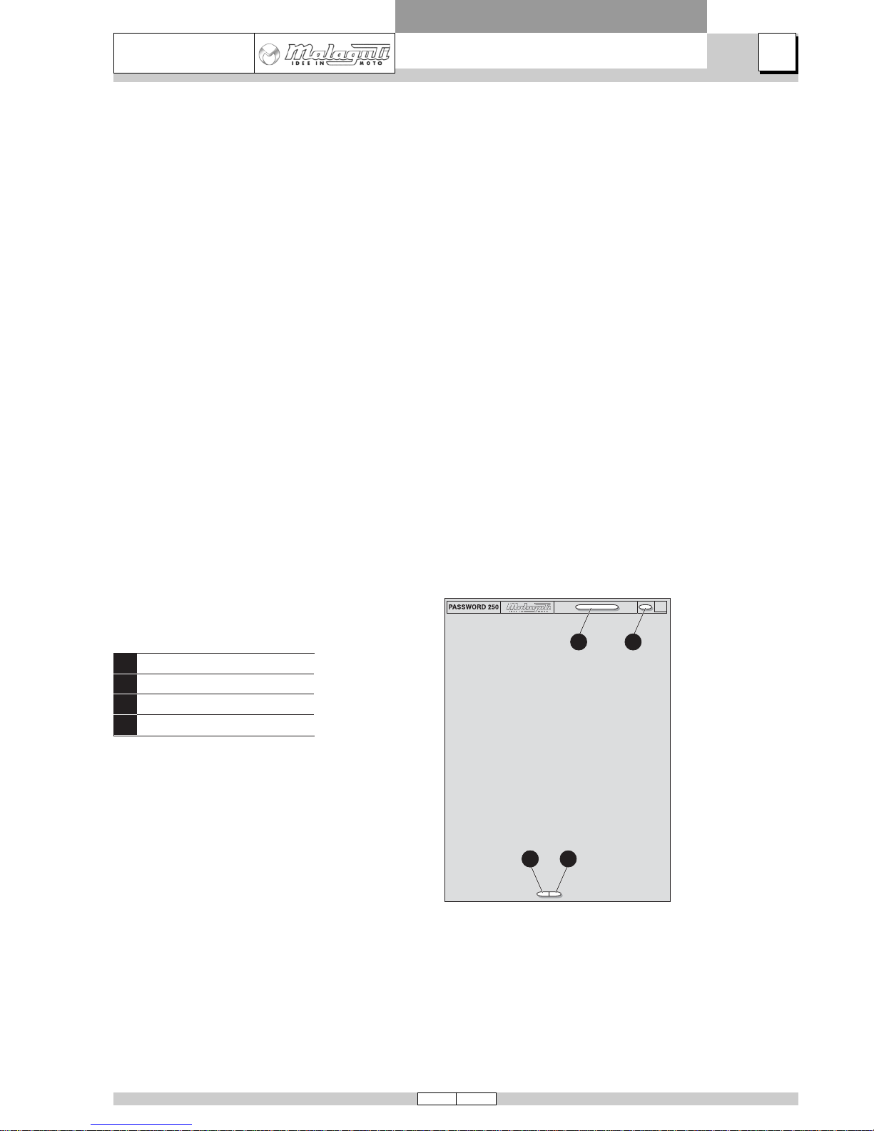
CONFIGURATION OF THE PAGES
MODIFIED P A GES
• Pages that have been modified will bear the same number as the same page of the previous edition, followed by a
letter M and, in the relative box, the new date of issue.
ADDITIONAL P AGES
• Any additional pages shall bear the last number of the section to which they belong, followed by the letter A and the
new edition date.
INTRODUCTION
Y
X
W
Z
Chapter
Section title
Page N°
Date of issue

6 05/06
A
1
MADISON 3
250 ie
FRAME AND RUNNING GEAR
INTRODUCTION
SYMBOLS
• Symbols are provided for quick and easy reference (see the relevant heading), identifying situations requiring
utmost attention or providing practical suggestions or simple information.
• These symbols may appear next to a text (in which case they refer solely to the text itself), next to a figure (in
which case they refer to the topic illustrated in the figure and to the relative text), or at the top of the page (in which
case they refer to all the topics dealt with in the page).
NOTE The meaning of the symbols should be duly memorised as their scope is to avoid having to repeat
basic technical concepts or safety recommendations. They are therefore to be considered as “memory tags”. In case of any doubt as to their meaning, consult the page in which they are fully described.
UNITS OF MEASUREMENT
All the dimensions in this Manual are shown in mm.
NOTE The letter V in the illustrations refers to fixing or adjusting screws. The number following this letter
refers to the number of the same type of screw in the unit or component described and illustrated. A
letter without a number indicates quantity 1. In case of different screws being referred to in the illustration, the letter V is followed by a number and a lower case letter. Example: (V4a).
Unless otherwise specified, units and components are reassembled by proceeding in the reverse
order of removal.
F
Cs
P
Pr
S
Sc
T
V
Figure
Tightening torque
Page
Paragraph
Section
Diagram
Table
Screw
F
Cs
P
Pr
S
Sc
T
V
ABBREVIATIONS
7 05/06
A
1
MADISON 3
250 ie
FRAME AND RUNNING GEAR
INTRODUCTION
GENERAL WORK PROCEDURES
• The ad vice, recommendations and warnings given hereafter are aimed at ensuring maximum work safety as well
as at considerably reducing the risk of accidents, personal injury, equipment damage and idle times. We therefore
recommend observing such advice, recommendations and warnings scrupulously.
SUGGESTIONS
• Only use top quality tools and equipment.
• Only use equipment conforming to EU Directives for lifting the vehicle.
• During all operations keep tools close at hand, ideally in accordance with a predetermined sequence of use, and
anyway never leave tools on the vehicle or in concealed or hard to reach positions.
• Always keep the work area clean and tidy.
• When tightening screws or nuts, start with the larger diameter or inner fasteners, and tighten them in a “crosswise
pattern” in successive “torquing steps”.
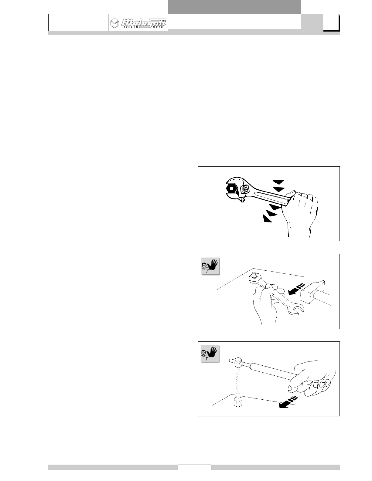
• Preferably use open-end wrenches and tighten by exerting “pulling force” rather than “pushing force”.
• Adjustable wrenches should only be used in case of
emergency, i.e. when a properly sized wrench is not
available. During the torquing stage the movable jaw
tends to open thus risking damaging the screw head or
achieving unreliable tightening torque values. In any
case, when using an adjustable wrench, take care to
proceed as shown in the figure.
• Except in the case of occasional services, prepare a
work sheet for the customer, on which to take a note
of all the work performed and write memos relating to
any future checks that may be required.
RECOMMENDATIONS
• Before carrying out any work on the vehicle wait for
all the parts to cool down completely.
• For operations requiring two mechanics, make sure that
the various steps to be performed by each of them are
clearly defined and coordinated beforehand.
• Make sure that each component has been properly fitted before proceeding with the next one.
• Lubricate all parts (where applicable) before reinstalling them.
• Gaskets, oil seals, snap rings and cotters must be re-
newed at every refitting.
• The torque settings specified in the manuals refer to
the “final torque”, which must be reached progressively
by steps.
• Loosen and tighten aluminium alloy parts (covers) only
after the engine has cooled down fully.
• Only use screwdrivers of suitable sizes in relation to
the screws to be loosened or tightened.
• Work in a comfortable position and ensure that the vehicle is stable.
• Never use a screwdriver as a lever or chisel.
• Never use pliers to loosen or tighten screws or nuts because, in addition to not providing a sufficient clamping force,
they may also damage the screw head or nut hex.
• Never tap wrenches with a hammer (or other similar tools) to loosen or tighten screws and nuts.
• Never attempt to increase leverage by attaching tubes, etc. to wrenches.
8 05/06
A
1
MADISON 3
250 ie
FRAME AND RUNNING GEAR
INTRODUCTION
A
Never use open flames for an y reason.
Never leave open containers or containers not suitable for holding fuel in passageways, close to
heat sources. etc.
Never use petrol to clean the vehicle or the workshop floor. Al ways use low flash point solvents to
clean the vehicle components.
Never suck from or blow into the fuel pipe.
When welding, make sure that there are no flammable liquids in the vicinity. Always remo ve the fuel
tank, even if completely empty, and disconnect the negative cable (-) from the battery.
Never leave the engine running in closed or poorl y ventilated areas.
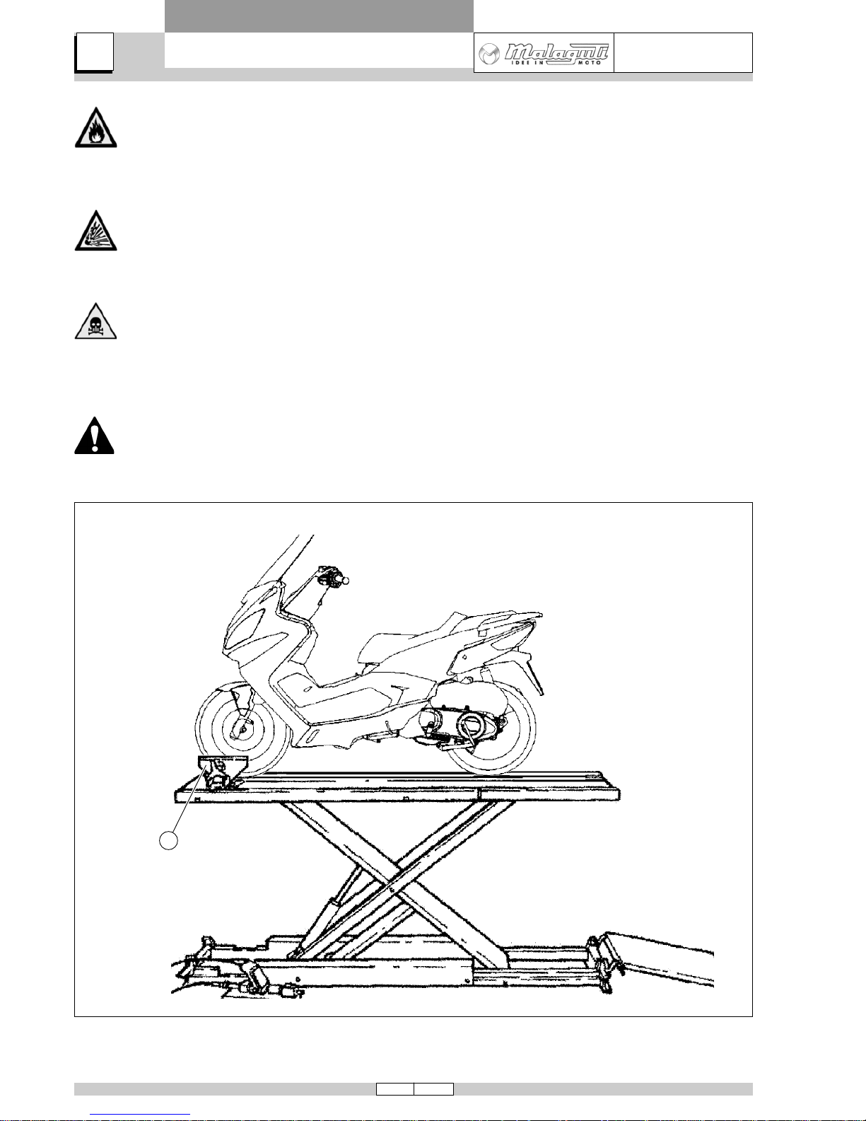
Before any servicing, make sure that the vehic le is perf ectl y stable.
The front wheel should preferably be anchored to fixture (A), which is integral with the lift platf orm.

9 05/06
A
1
MADISON 3
250 ie
FRAME AND RUNNING GEAR
INTRODUCTION
OPERATING SYMBOLS
IMPORTANT!
CAUTION! - Descriptions concerning operations that are potentially hazardous for the maintenance
mechanic or repairman, other workshop personnel or extraneous persons, for the environment, for the
vehicle, and for the tools and equipment.
DISCONNECT POWER - Before performing the work described, disconnect the battery negative cable.
RISK OF FIRE - Indicates operations that may constitute a fire hazard.
EXPLOSION HAZARD - Indicates operations that may constitute a risk of explosion.
TOXIC FUMES - Indicates the risk of intoxication or inflammation of the respiratory tract.
NO! - Operations to be absolutely avoided.
SYMMETRICAL OPERA TIONS - Operations to repeat on both sides of the unit or component in question.
ENGINE WORKSHOP MANUAL - Information that can be found in the engine workshop manual.
FITTING AND ASSEMBLY OPERATIONS
REMOVAL AND DISASSEMBLY OPERATIONS
10 05/06
A
2
MADISON 3
250 ie
FRAME AND RUNNING GEAR
C
A
B
D
06039483
TECHNICAL DATA
MALAGUTI SpA reserves the right to modify technical data at any time without prior notice.
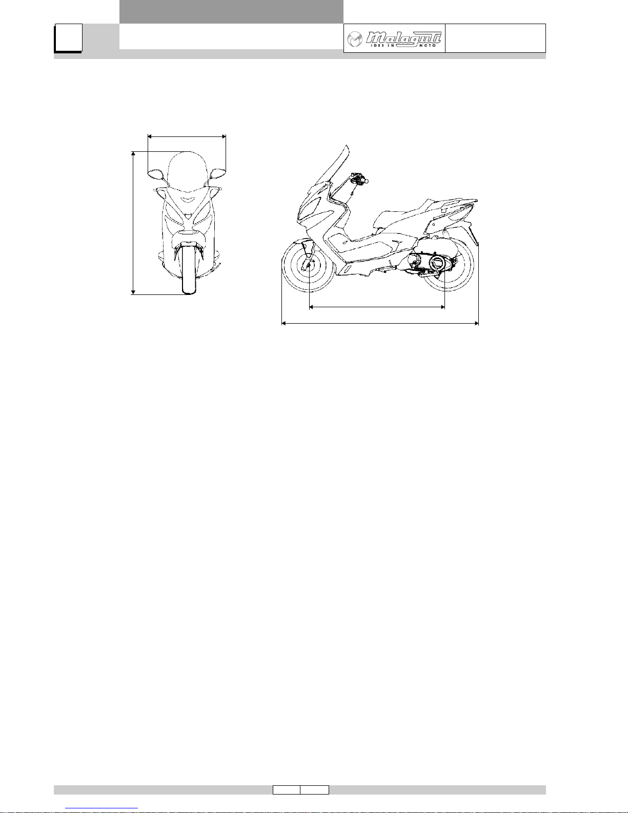
DIMENSIONS
wheel base (A), m .................................................1.410
max. length (B), m .................................................1.980
max. width (C), m ..................................................0.790
max. height (D), m .................................................1.640
kerbside weight, Kg ..................................................165
max. load with rider, pillion and luggage, Kg .............185
CAPACITY
engine oil, cc ........................................................ 1300*
transmission oil cc .................................................. 250*
fuel tank (reserve), l...........................................8.5* (3*)
* Guideline value
ENGINE: 4-VAL VE SINGLE-CYLINDER PIAGGIO
type ....................................................................M366M
n° of cylinders...............................................................1
bore x stroke, mm........................................... Ø 72 x 60
displacement, cm3....................................................244
compression ratio ...........................................11±0.5 : 1
cooling................................................................... liquid
starting system ........................................ electric starter
lubrication system........................................... wet sump
SPARK PLUG
type: .............................................CHAMPION RG4 HP
...........................................................NGK CR8EB
TRANSMISSION
Expandable pulley automatic variator, V-belt, automatic dry
centrifugal clutch, secondary drive gearbox and transmission housing with forced circulation cooling system.
FUEL SYSTEM
Electronic injection with electric fuel pump.
Fuel: unleaded petrol.
ELECTRONIC IGNITION
High efficiency inductive coil integrated with injection, variable ignition advance and separate H.T. coil.
BRAKES
Front: 240 mm disk with hydraulic transmission and
calliper with two pistons
Rear: 240 mm disk with hydraulic transmission and
calliper
FRAME
Frame made with single steel tube split at footboard level.
SUSPENSION
Front: Hydraulic fork Ø 36 mm - travel: 130 mm
Rear: N.2 hydraulic shock absorbers with adjusta-
ble spring preload - travel: 75 mm.
BATTERY
Type: 12V, 12Ah; sealed unit.
TYRES
Front: ————— 120/70 - 14 55P
Rear: ————— 140/60 - 14 64P
It is possible to use tyres with load and speed indexes that
are higher than or identical to those indicated. It is however necessary for speed indexes to be identical for both
tyres.
GETTING TO KNOW
YOUR SCOOTER
11 05/06
A
MADISON 3
250 ie
GETTING TO KNOW
YOUR SCOOTER
FRAME AND RUNNING GEAR
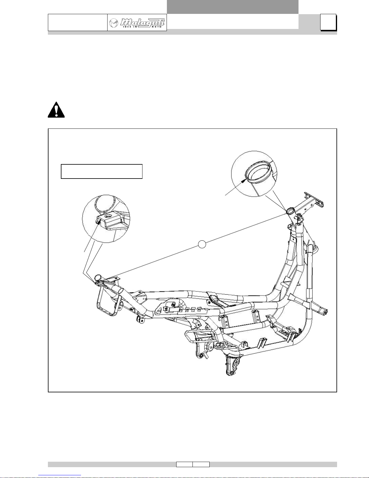
A = 1220 ± 2 mm
A
06039484
DIMENSIONAL CHECK OF FRAME
If the scooter has been involved in an accident and you suspect even slight distortion of the frame it is essential to
perform the dimensional checking procedure before any further “repair or set-up” work.
Control dimension (A) must be 1220 mm with a tolerance of ± 2 mm.
Do not attempt to bend the frame to restore the original “A” measurement.

12 05/06
A
3
MADISON 3
250 ie
FRAME AND RUNNING GEAR
1
2
3
4
**
*
*
*
5
6
7
8
9
*
*
**
*
*
*
*
*
*
**
*
*
*
**
**
*
**
*
*
*
**
*
*
*
*
*
**
*
*
*
*
*
*
**
**
*
**
**
*
*
*
**
*
**
**
*
**
**
*
**
**
*
**
**
*
**
**
*
**
**
*
**
*
*
*
**
**
*
MAINTENANCE T ABLE
= first service
= change
= adjustment
= clean = inspection
CHECKS AND REPLACEMENT OPERATIONS
FIRST 1000km5000 km
or
10 months
10000 km
or
20 months
15000 km
or
30 months
20000 km
or
40 months
25000 km
or
50 months
30000 km
or
60 months
35000 km
or
70 months
40000 km
or
80 months
45000 km
or
90 months
50000 km
or
100 months
55000 km
or
110 months
60000 km
or
120 months
65000 km
or
130 months
70000 km
or
140 months
75000 km
or
150 months
80000 km
or
160 months
Spark plug
Engine oil and oil filter
Gearbox oil
Valves
Drive belt
Variator shoes / rollers
Tightness of brake lines - Injection system
Fuel pump filter
Air filter
Drive belt housing air filter
Electrical system, battery and charge level
Brake pads - condition and wear
Level and density of coolant (change every 2 years) –
Correct fitting and tightness of hoses
Brake fluid circuit
Wheel bearings
Frame linkages
Steering operation and play (lubricate if necessary)
Operation and oil-tightness of fork and shock absorbers
Tightness of nuts and bolts
Tightness of side and centre stands – Pivot lubrication
Operation of side stand switch - Lubrication
Throttle control
Tyre pressure – Tread wear
Final check:
Condition of tyres - Pressure – Lights Indicators - Switch functions - Road test
If the periodic drive belt inspection (every 10000 km) reveals excessive wear in relation to the conditions of use,
reduce the intervals between future services.
The maintenance schedule is based on average riding conditions. Machines subject to severe use or ridden in unusually wet or dusty conditions or off the road require more frequent servicing.
Certain simple checks, i. e . those marked with an asterisk, MAY be performed under the direct responsibility of technicians not specifically authorised by MALA GUTI.
Every 2000 km
Every 20 months or 10000 km
MAINTENANCE

13
A
4
05/06
MADISON 3
250 ie
FRAME AND RUNNING GEAR
06039057_1
06039029_1
06039035_1
A
V2
D
A
REAR-VIEW MIRRORS
• Lift rubber boot then undo nut (D) and mirror (A).
RIGHT-HAND MIRROR is fitted by screwing
it COUNTER-CLOCKWISE.
LEFT -HAND MIRROR is fitted b y screwing it
CLOCKWISE.
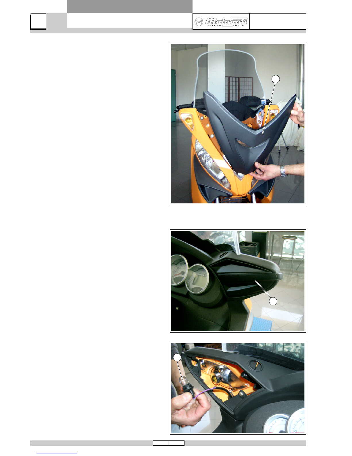
CENTRAL FAIRING
• Remove panels (A) by prising with a screwdriver.
• Undo screws (V2).
DISASSEMBLY
14 05/06
A
4
MADISON 3
250 ie
FRAME AND RUNNING GEAR
DISASSEMBLY
06039041_1
06039032_1
06039029_1
B
A
B
• Disengage central fairing (B) and remove it from scooter, rotating it forwards.
CHANGING THE FRONT TURN INDICA TOR
BULB
• Remove panels (A) by prising with a screwdriver.
• Turn bulb-holder ringnut (B) counter-clockwise and
remove.
• Extract bulb by pulling it.
15
A
4
05/06
MADISON 3
250 ie
FRAME AND RUNNING GEAR
DISASSEMBLY
06039045_1
V6
V6
A
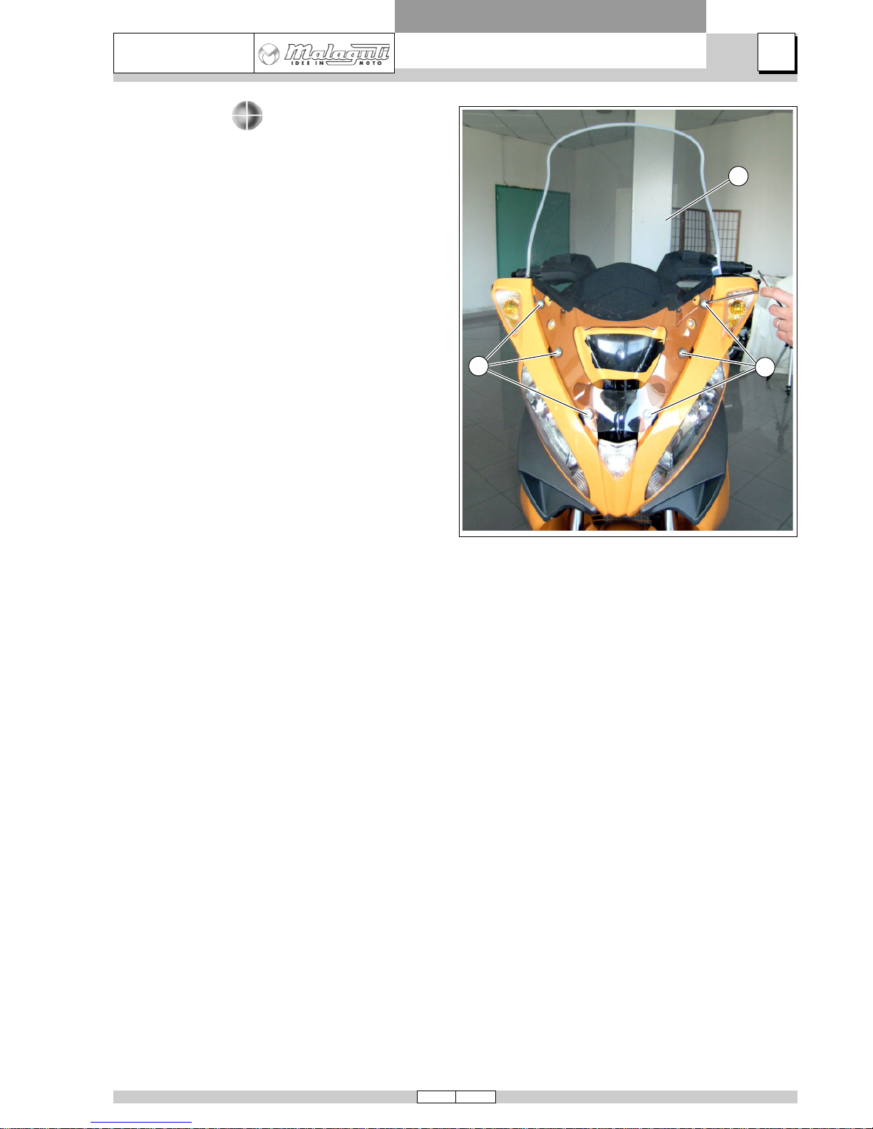
WINDSHIELD
• (Remove central fairing).
• Undo screws (V6).
• Remove windshield (A).
• Recover the rubber grommets under the screws.
16 05/06
A
4
MADISON 3
250 ie
FRAME AND RUNNING GEAR
DISASSEMBLY
06039048_1
06039059_1
06039060_1
V2a
A
V2b
G
F
D
A
E
C
H
S
B
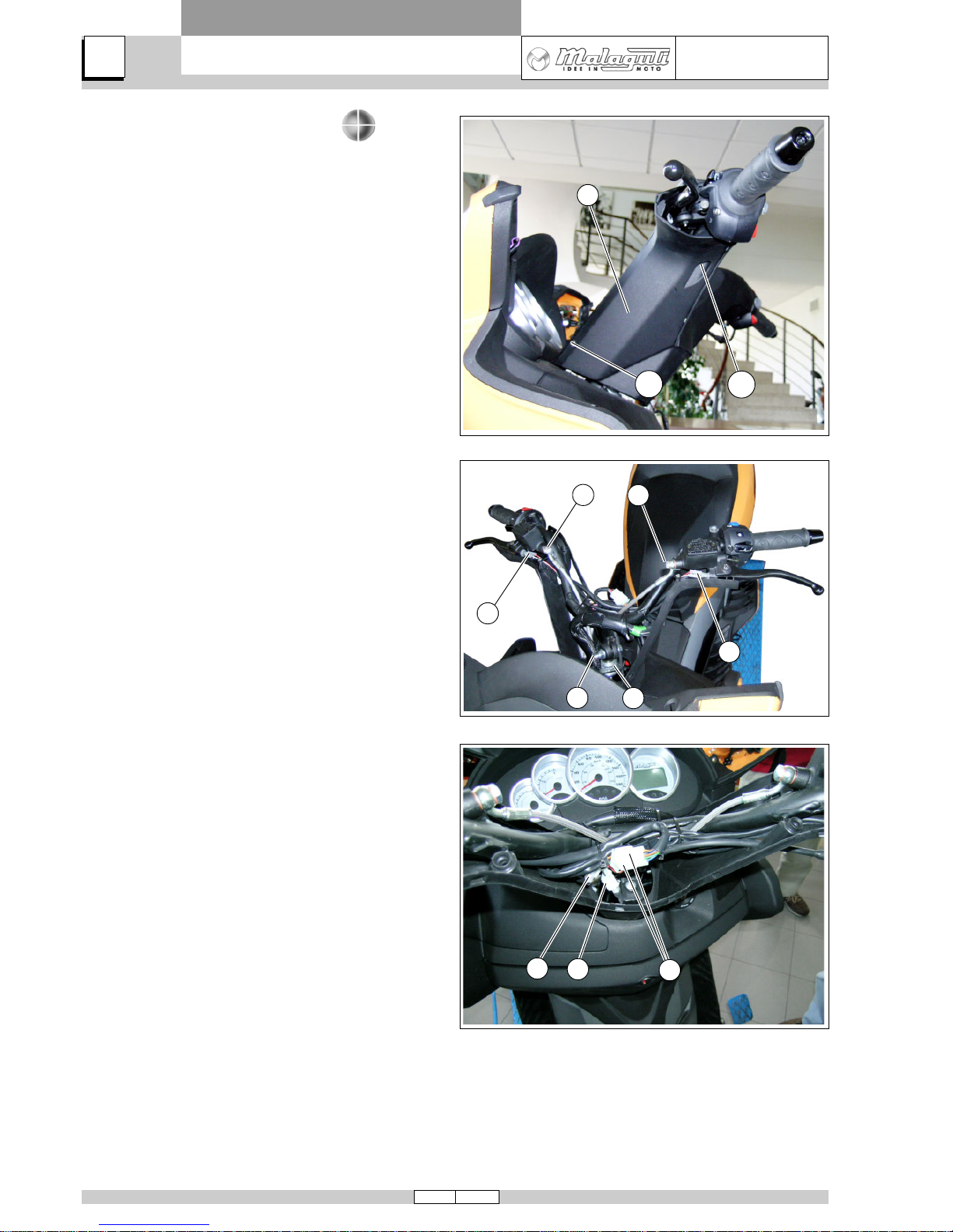
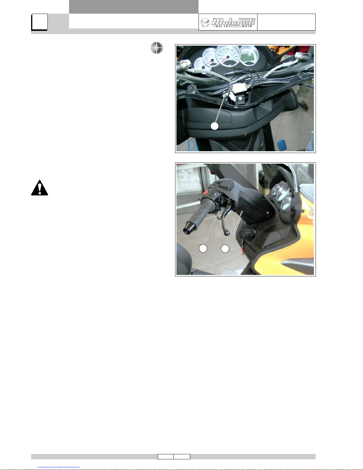
UPPER HANDLEBAR COVER
• (Remove rear-view mirrors).
• Undo screws (V2a) and (V2b).
• Remove upper handlebar cover (A).
ACCESSIBILITY
Removing the front handlebar cover provides access to
the following components:
• Handlebar screw (A);
• connector for LH handlebar control (B);
• ambient temperature sensor connector (C);
• RH control STOP switch (D);
• LH control STOP switch (E);
• rear brake master cylinder union (F);
• front brake master cylinder union (G);
• resistance connector (H);
• steering adjustment ringnuts (S).
17
A
4
05/06
MADISON 3
250 ie
FRAME AND RUNNING GEAR
DISASSEMBLY
06039385
06039386
V2
V
A
B
V
V2
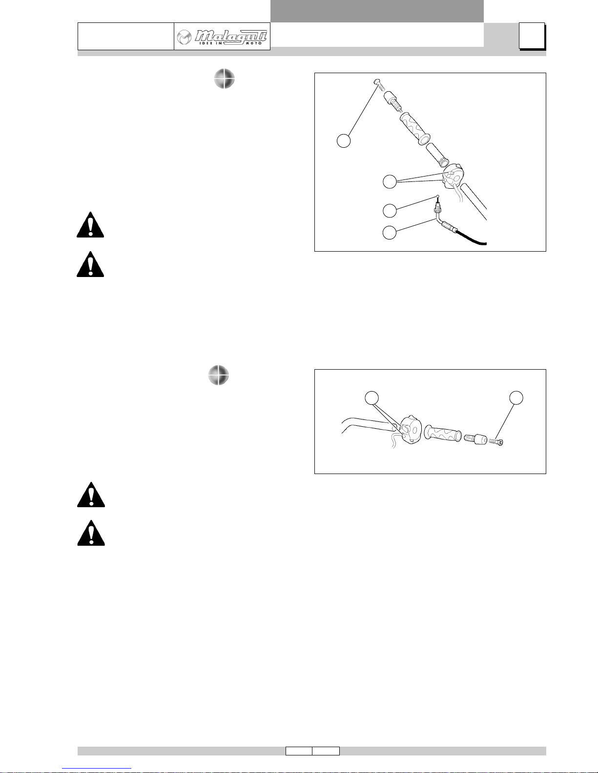
RIGHT-HAND CONTROL
• (Remove rear-view mirrors).
• (Remove upper handlebar cover).
• Unscrew union (B).
• Undo screw (V) and remove counterweight.
• Disconnect wiring connectors.
• Undo screws (V2) and remove throttle control.
• Disconnect throttle opening (A) cables.
Use compressed air to reduce friction when
removing and refitting the twist grip.
At time of reassembly shorter screw (V2)
must be located in UPPER part of control.
LEFT-HAND CONTROL
• (Remove rear-view mirrors).
• (Remove upper handlebar cover).
• Disconnect switch connector.
• Undo screw (V) and remove counterweight.
• Undo screws (V2) and remove LH control.
Use compressed air to reduce friction when
removing and refitting the twist grip.
At time of reassembly shorter screw (V2)
must be located in UPPER part of control.
18 05/06
A
4
MADISON 3
250 ie
FRAME AND RUNNING GEAR
DISASSEMBLY
06039021_1
06039060_1
A
B
C
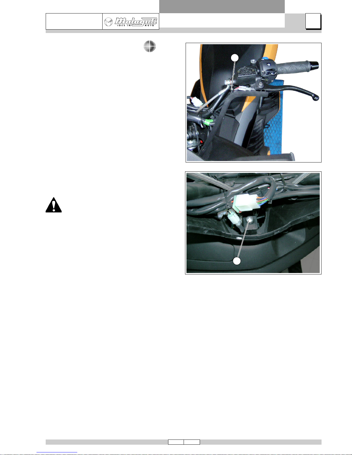
AMBIENT TEMPERATURE SENSOR
• (Remove rear-view mirrors).
• (Remove upper handlebar cover).
• Detach the connector (A).
• Remove sensor (B) from lower handlebar cover (C).
The sensor must be mounted EXTERNALLY to the lower handlebar cover, as shown
in the figure.
19
A
4
05/06
MADISON 3
250 ie
FRAME AND RUNNING GEAR
DISASSEMBLY
06039061_1
06039062_1
V2
V
HANDLEBAR LOWER COVER
• (Remove rear-view mirrors).
• (Remove upper handlebar cover).
• (Remove right-hand control).
• (Remove ambient temperature sensor).
• Undo screws (V2).
• Undo screw (V).
• Remove lower handlebar cover.
To remove handlebar cover completely, disconnect the two right-hand control connectors.
20 05/06
A
4
MADISON 3
250 ie
FRAME AND RUNNING GEAR
DISASSEMBLY
06039085_1
06039082_1
06039086_1
V
V4a
V4b
A
B
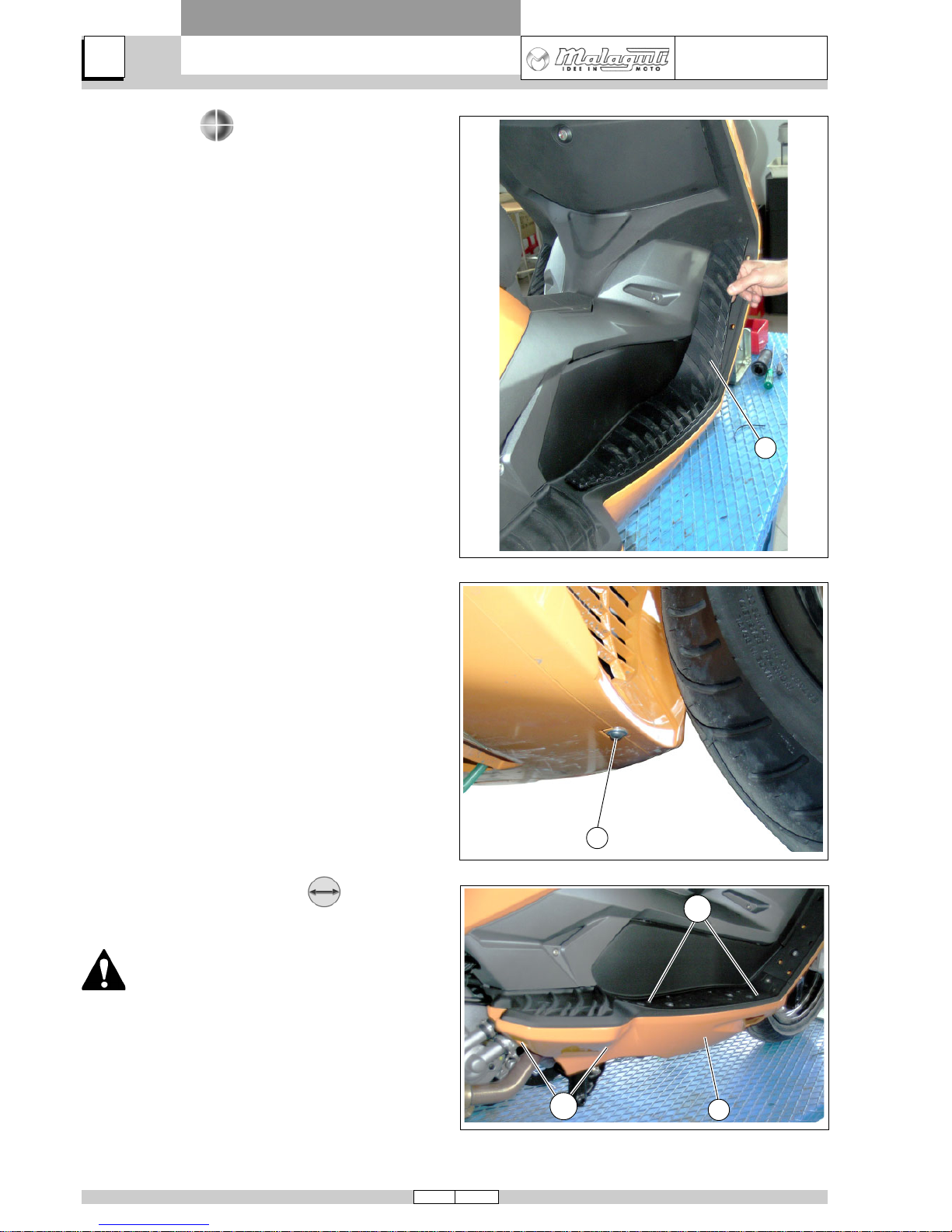
SUB PANEL
• Remove footboards (A).
• Undo screw (V).
• Undo screws (V4a) and (V4b).
• Remove sub-panel (B).
Screws (V4a) are longer than screws (V4b).

21
A
4
05/06
MADISON 3
250 ie
FRAME AND RUNNING GEAR
DISASSEMBLY
06039090_1
06039088_1
06039227_1
C
D
B
A
ACCESSIBILITY
Removing the sub panel provides access to the following
components:
• Ignition coil (A).
• Bank angle sensor (B).
• Radiator drain plug (C).
• Side stand switch (D).
22 05/06
A
4
MADISON 3
250 ie
FRAME AND RUNNING GEAR
DISASSEMBLY
06039095_2
06039095_2
V2
30 ± 20%
2 mm
V
V2
V
V
20 ± 10%
SPEEDOMETER SENSOR
• Undo screw (V) ensuring the spacer does not fall.
• Disconnect the electronic transmission connector.
When refitting, use a feeler gauge, to check
that the sensor - disc gap is 1÷2 mm.
• Remove the sensor complete with the transmission.
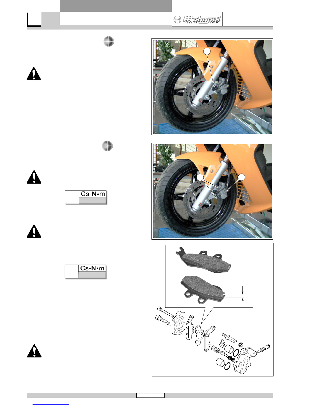
FRONT BRAKE CALIPER
• Undo the screw of the hydraulic transmission (V) and
remove the hydraulic transmission and its gaskets.
When reassembling, replace the gaskets of
the hydraulic transmission.
• Undo screws (V2) and free the complete caliper.
After having removed the hydraulic transmission and the caliper from its seat, place a recipient under it to collect the brake
fluid. Dispose of used brake fluid in compliance with statutory legislation.
CHECKING FRONT BRAKE WEAR
• Take the opportunity to check also wear of the brake
disc. If they are scored or unevenly worn, they can be
reground.
If disc thickness has worn to less than 3.5 mm the
discs must be changed.
Minimum thickness of the pads is 2 mm.
Note For overhauling the caliper, see the specific
Chapter.
23
A
4
05/06
MADISON 3
250 ie
FRAME AND RUNNING GEAR
DISASSEMBLY
D
80 ± 10%
06039093_1
06039096_1
06039095_2
D
V
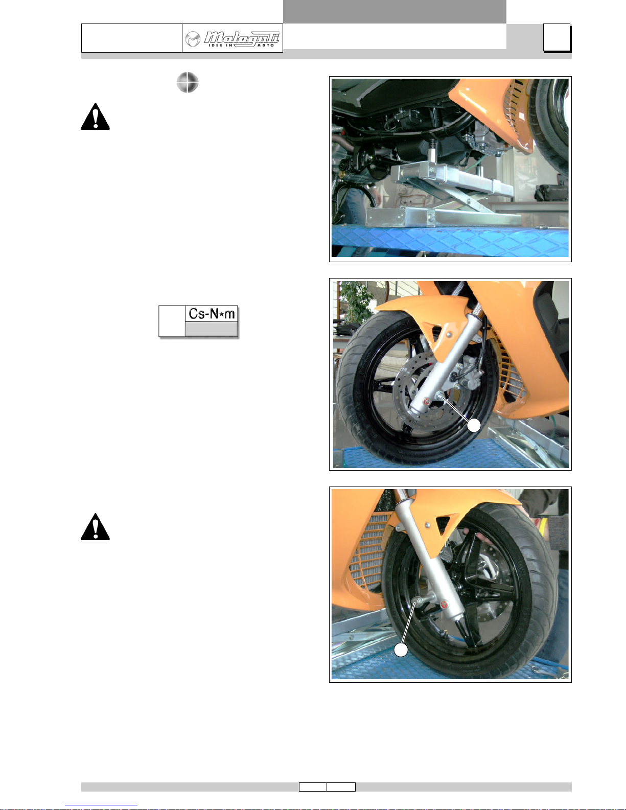
FRONT WHEEL
Before disassembly , support the frame at the
centre to prevent the scooter from falling.
For this purpose, remove sub-panel and place a stand under frame cradles as shown.
• Undo the nut (D).
• Pull out the spindle (V); then remove the wheel.
Pay attention to spacer s located on spindle
(V).
 Loading...