

Malaguti MADISON 3 125 cc Workshop Manual

MADISON 125 cc. - Euro 3
B
TROUBLESHOOTING
ELECTRICAL SYSTEM
WORKSHOP MANUAL
2 08.06
B
MADISON 125 cc
Introduction
CHAPTER
PAGE ISSUE
ENGLISH
X
Y
Z W
J
INTRODUCTION
- This publication describes all necessary steps for troubleshooting concerning the electrical system and
the possible service operations, which are necessary for their solution. It supplies the trade technicians
(Authorised Service Centres) with the necessary information for operating in compliance with the modern concepts
of “good practice” and “safety at work”.
- Further information can be derived from the “Chassis” Workshop Manual - from the “Engine” Workshop
Manual - from the Spare Parts Catalogue.
- All described operations must be performed by technicians with the necessary skill and experience.
- The steps for removal of body parts and of electrical and mechanical components, to allow access to wiring or
electric components to service, can be taken from the “Chassis” Workshop Manual.
- We recommend you follow the information given in this publication with care.
- For any further information you may need, refer to the Malaguti S.p.A. Technical Department.
- It is essential to follow the instructions with great care. Work carried out carelessly or, worse still, work that
has not been accomplished, can cause injuries and damage or, in the less serious cases, tiresome complaints.
NOTES FOR EASY CONSULTATION
PAGE LAYOUT
X
Y Chapter
X Motor vehicle model
J Section
W Page N
Z Date of issue
ABBREVIATIONS
F. Figure
Pag. Page
Pr Paragraph
S Section
Sch Diagram
T Table
MODIFIED PAGES
- Modified pages shall bear the same number as those in the previous edition, followed by the letter M, with the
new date of issue appearing in the appropriate box.
- Modified pages may contain new illustrations; in this case, the added illustration (or illustrations) will bear the
number of the former illustration, followed by a letter.
- Negative illustration numbers (such as for instance F. 5 ) mean that the previous numbers have been
intentionally omitted.
ADDITIONAL PAGES
- Any additional pages shall bear the last number of the section to which they belong, followed by the letter A and
the new date of issue.
08.06 3
MADISON 125 cc
Introduction
B
CHAPTER
ISSUE PAGE
ENGLISH
FIRST EDITION : 08/06
OPERATIONAL SYMBOLS
IMPORTANT!
CAUTION! - situations entailing the risk of personal injury to maintenance or repair mechanics, other
workshop personnel or third parties, or damage to environment, vehicle or equipment.
ENGINE OFF - operations to be informed with the engine off.
CUT OFF POWER - before performing the operation described, disconnect the battery negative.
MECHANICAL MAINTENANCE - operations to be performed only by an expert mechanic.
ELECTRICAL MAINTENANCE - operations to be performed only by an expert electrical/electronic
technician.
NO! - Operations to be absolutely avoided.
WARNINGS
- Before any servicing, make sure that the vehicle is perfectly stable.
The front wheel should preferably be anchored to the equipment integral with the lifting board.
- For checks and calibration, use tools of an ascertained quality and never empirical means or tools with a
limited reliability.
- “Malaguti S.p.A.” declines all responsibility for damage of any kind caused by use of inadequate systems for
checking the electrical and electronic equipment.
- “Malaguti” reserves the right to make any and all changes to its vehicles as it deems fit and appropriate at any
time without prior notice.
- No part of this publication, whether text or illustrations, may be reproduced or circulated. “Malaguti”
reserves all rights over this publication. Reasons must be given for any request for permission (written) thereto.

4 08.06
B
MADISON 125 cc
Introduction
CHAPTER
PAGE ISSUE
ENGLISH
Table of contents
Page
Introduction 2
Checking Switches 6
Fuses 8
General Wiring Diagram 11
Ignition System 14
Charging System 16
Electrical Starting System 18
Light System 20
Signalling System 25

08.06 5
MADISON 125 cc
Introduction
B
CHAPTER
ISSUE PAGE
ENGLISH
TECHNICAL TERM DICTIONARY
• Multimeter (Tester) (code n° 08609500)
• V = (DC): direct current (supply from battery)
• V ~ (AC): alternating current (supply from flywheel)
• A: Ampere = the unit of electric current
• W: Watt = the unit of electric power (result of Volts by Amps A x V = W)
•
::
::
:?: OHM = the unit of electrical resistance
• Infinite OHM = tester prods disconnected or cable interrupted
• OHM = 0: continuity with tester prods connected and cable not interrupted
• PIN: connector terminal
• Line: cable between two PINS
• < = less than
•
= less than or equal to
• > = greater than
•
= greater than or equal to
• KPa (o bar): the unit of pressure (100 KPa = 1 bar)
• ÷ = from - to
• ~ = approximately
6 08.06
PAGE ISSUE
B
MADISON 125 cc
Checking Switches
CHAPTER
ENGLISH
CHECKING SWITCHES
CHECKING PROCEDURES
- Using a Tester (code n°08609500), check switches. In particular, check continuity between terminals to make
sure they are correctly connected.
- Replace the switch, even if only one of the possible combinations does not give the requested result.
Set the tester to function
::
::
:.
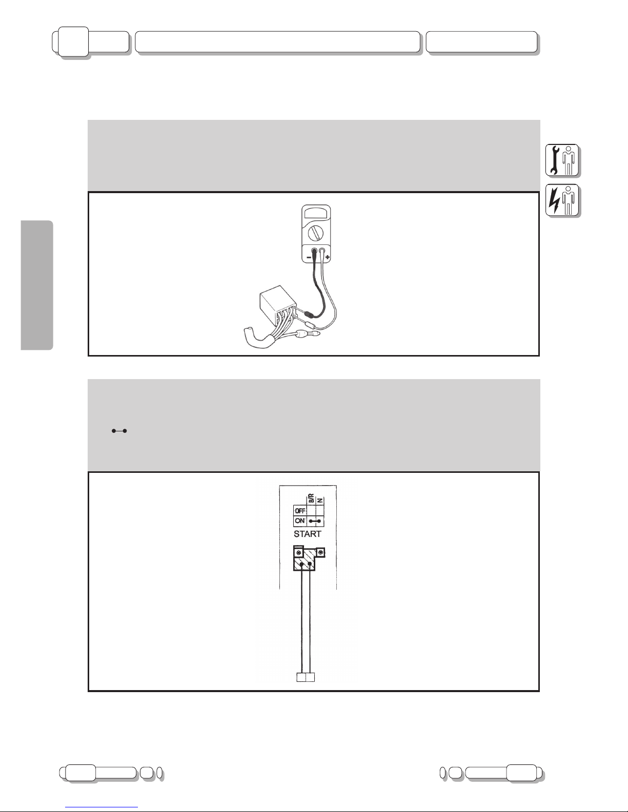
CONNECTION OF SWITCHES DESCRIBED IN THIS MANUAL
- This manual contains connection diagrams, like the one illustrated here below, which illustrate how switch
terminals should be connected (key switch, brake switch, “Mode” button, etc.).
- The first column from the left indicates the different positions of the switch, the top line the colour of the wires
connected to the switch terminals.
- The symbol identifies terminals in which there is a condition of continuity, i.e. a closed circuit, in a certain
position of the switch.
- In this diagram:
- “B/R” and “N”: there is continuous contact when the switch is “ON”.
F. 1
F. 2

08.06 7
ISSUE PAGE
MADISON 125 cc
Checking Switches
B
CHAPTER
ENGLISH
9
10
11
3
2
1
6
7
8
1
4
3
2
5
6
7
8
9
10
11
12
13
B-GR
R
ON
0FF
LO
HI
AZ-B
GL-N
B-N
AR
N
B-GR
R
0FF
ON
ON
0FF
GL-N
RS
RS
BL
B-R
N
GL-BL
GL-B
B-BL
R
OFF
ON
BL-N
VR-N
N
BL
GL-B
BL-R
13
12
N
N
N
5
4
ON
0FF
R
L
BL
B-N
M
VL
VR
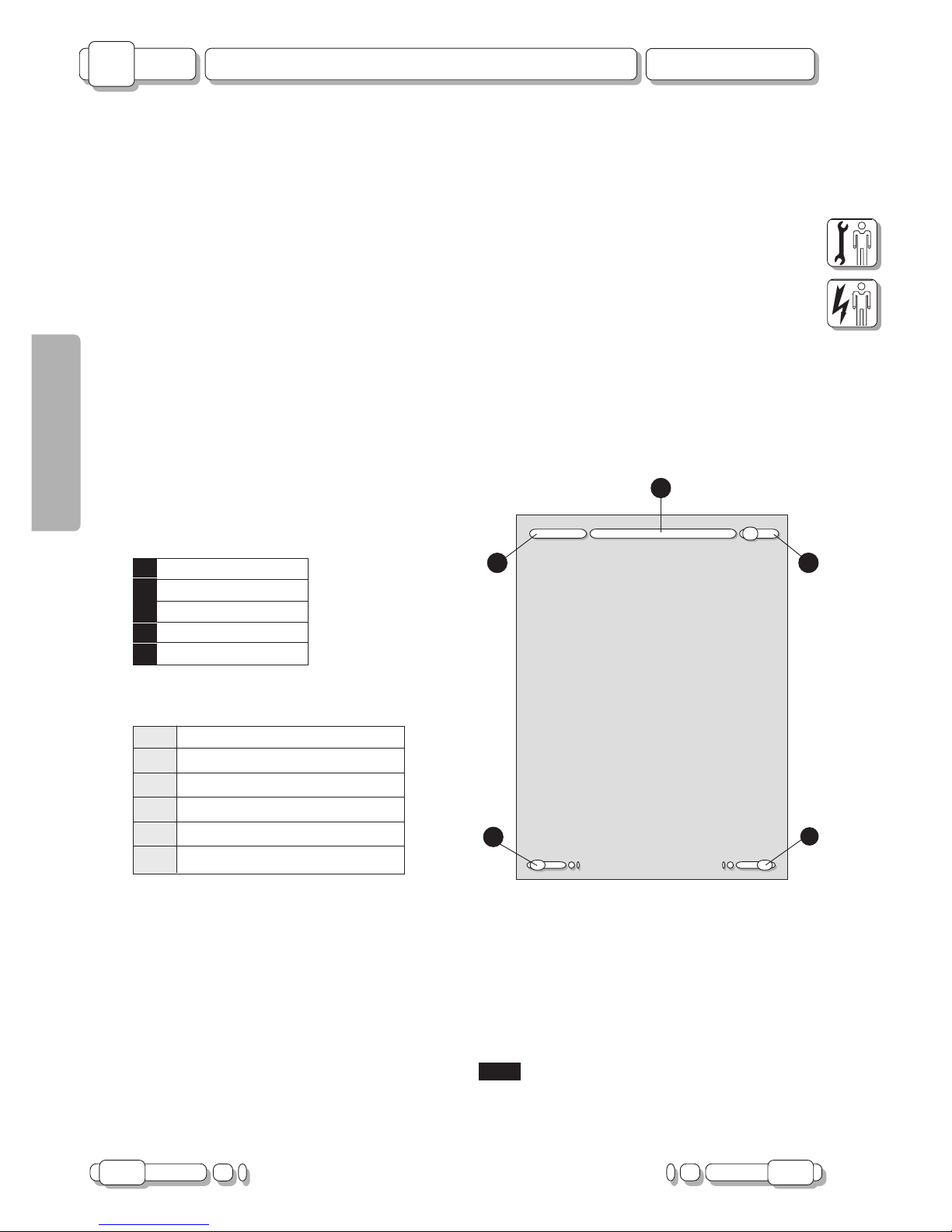
POSITION OF SWITCHES AND CONNECTION OF CONNECTORS
1) Rear stop switch 8) Engine start switch
2) Horn control 9) Engine stop switch
3) Light switch 10) Mode
4) Passing 11) Key switch
5) Turn indicator switch 12) Side stand switch
6) Front stop switch 13) Fuse carrier
7) Main light switch
NOTE: the start switch is closed when the START button is pressed.
The side stand switch is closed when the stand is idle.
The STOP switch is closed when the brake lever is operated.
8 08.06
PAGE ISSUE
B
MADISON 125 cc
Fuses
CHAPTER
ENGLISH
F. 3
FUSES
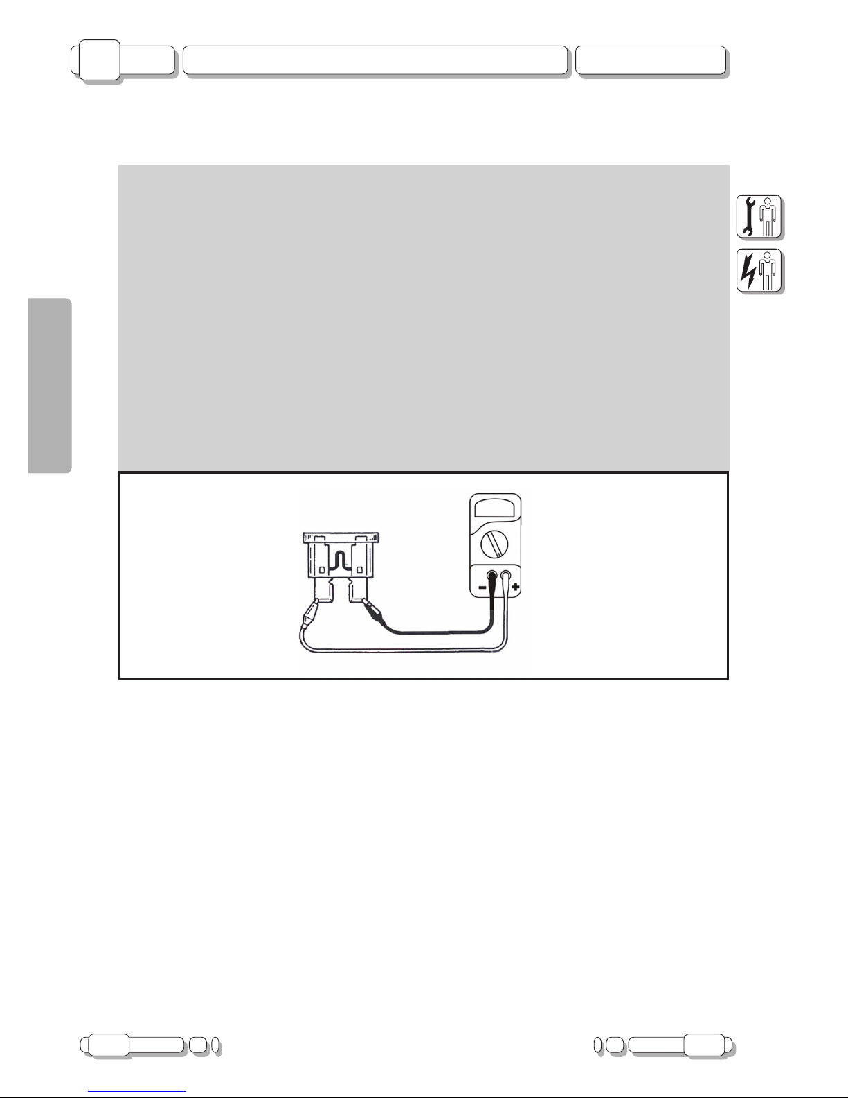
CHECKING FUSES
CAUTION: when checking fuses, always turn the main switch “OFF” or short-circuits may occur.
Checking procedure:
- Connect Tester (code n°08609500) to fuse and check continuity.
NOTE: put the Tester on “
::
::
:” (sound-emitting function).
- If the tester is showing “I” and no sound is given, replace the fuse.
Replacing procedure:
- Turn key “OFF”.
- Fit a new fuse with a correct amperage rating.
- Turn key “ON”.
- Turn switches on to check operation of the relative electrical systems.
- If the fuse blows again, check the relative circuit.
CAUTION: never use fuses with an amperage differing from that indicated. Use only fuses and never
other materials.
An unsuitable fuse can cause extensive damage to the electrical system, malfunctioning of the ignition
and light systems and even fires to break out.

08.06 9
ISSUE PAGE
MADISON 125 cc
Fuses
B
CHAPTER
ENGLISH
1 2 3 4 5 6 7 8
FUSES
The electrical equipment includes 10 fuses.
Before replacing a fuse, locate and eliminate the fault causing its interruption.
F. 4
F. 5
9) 30 A Recharge protection fuse
1) 15 A Lights
2) 7.5 A Turn indicators/stop
3) 3 A “ENGINE STOP”
4) 10 A Key
5) 30 A Main
6) - Not active
7) 7.5 A Radiator fan
8) 5 A 12 V Socket
10 08.06
PAGE ISSUE
B
MADISON 125 cc
Fuses
CHAPTER
ENGLISH
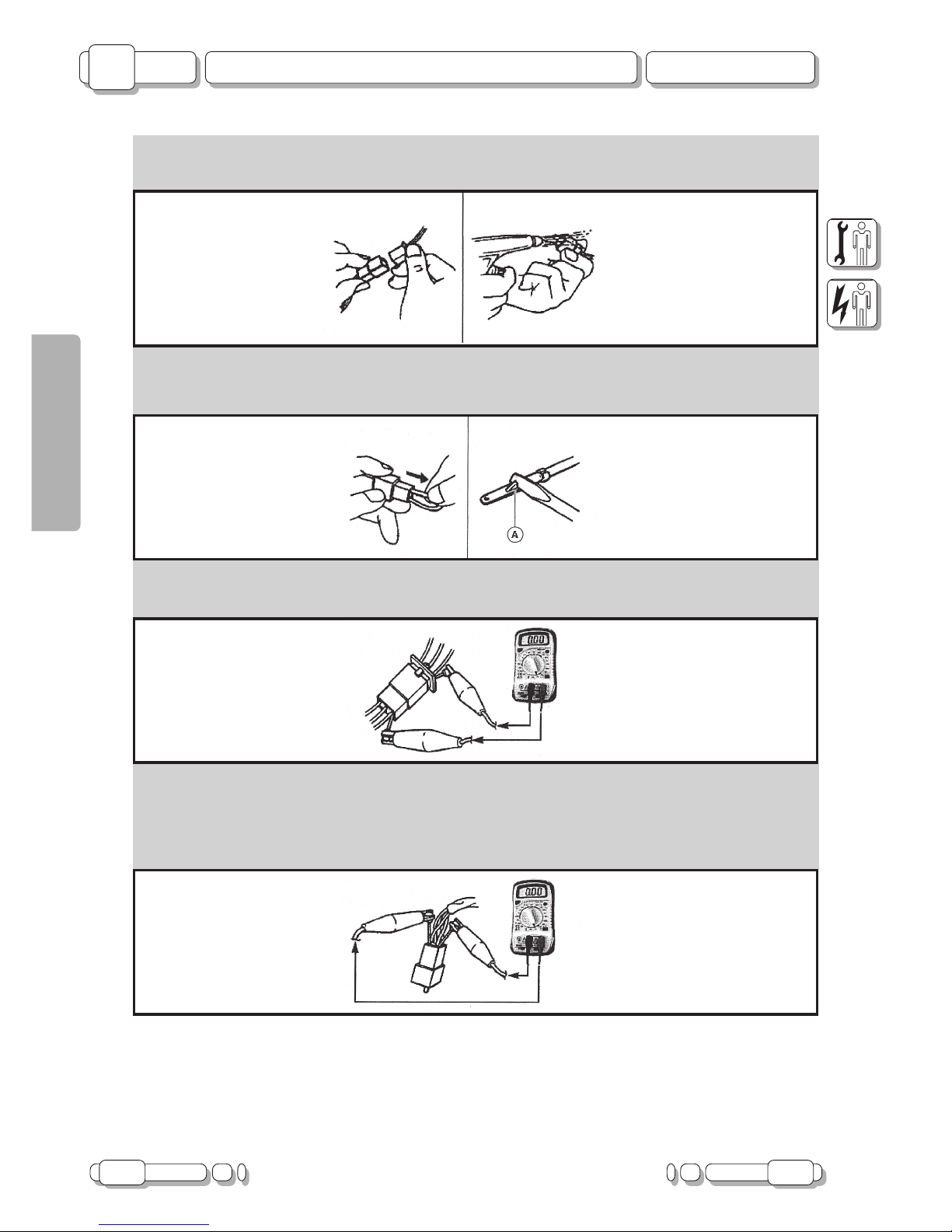
CHECKING CONNECTORS
- Check connectors for corrosion and damp.
- Disconnect connectors.
- Dry terminals with compressed air.
- Connect and disconnect connector two or three times.
- Pull connector to make sure it is correctly plugged in.
- If terminal is disconnected, bend stop (A) and refit terminal in connector.
- Plug in connectors.
NOTE: the “click” sound means that all connector parts are correctly assembled.
- Check continuity with a Tester.
NOTE: if there is no continuity, clean terminals.
As a temporary solution, use a contact cleaner.
Follow the instructions above to check the electrical equipment.
Use Tester as shown in the illustration.
F. 6
F. 7
F. 9
F. 8
08.06 11
MADISON 125 cc
General Wiring Diagram
B
CHAPTER
ENGLISH
ISSUE PAGE
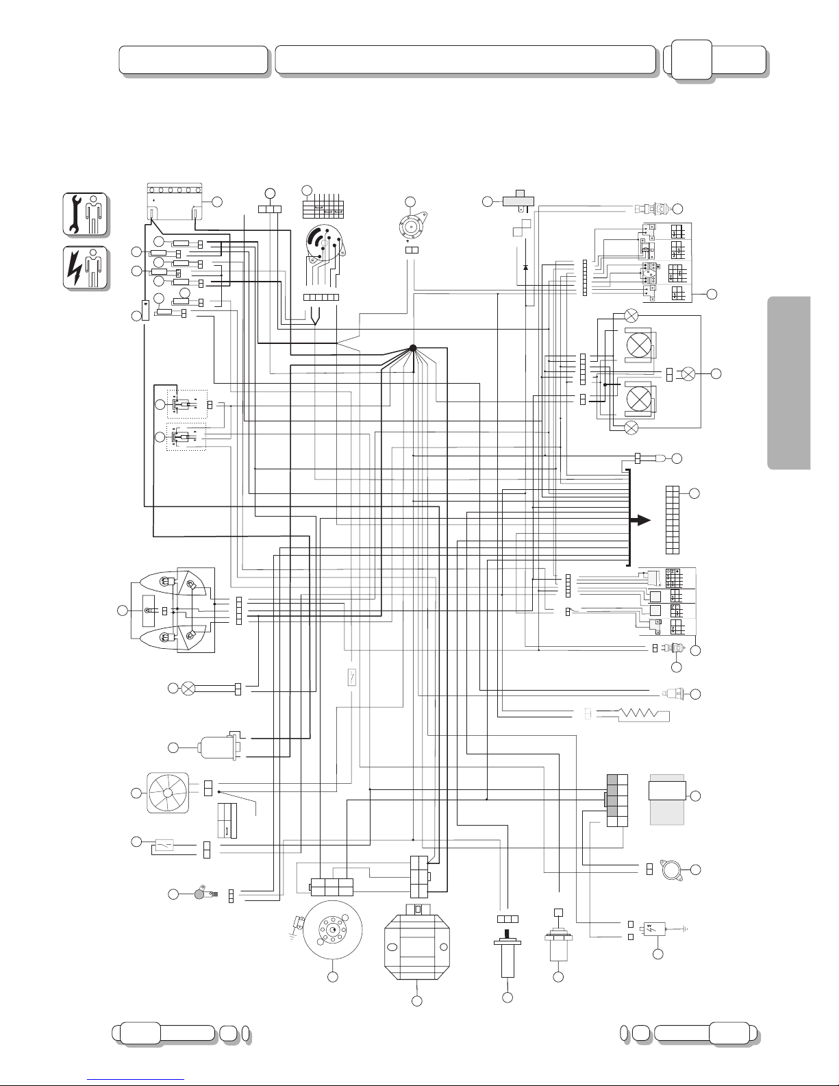
GENERAL WIRING DIAGRAM
FUSE15 A
3A
N
FUSE7.5 A
30A
BLBL
M-NM-N
VR
VR
VLVL
ARAR
ARAR
N
GL-N
GL-N
GL-NGL-N
BL
BL
B-NB-N
B-N
B-N
VRVR
VLVL
N
R-VRR-VR
AZ-BAZ-B
AZ-BAZ-B
M
VLVL
RSRS
R
N
VR
VR
VLVL
R
N
VR
VR
N
N
B
GL-BLGL-BL
R
BL
BL
R-VR
R-VR
GL-BGL-B
GL-NGL-N
BLBL
RSRS
RSRS
B-RB-R
B-R
B-R
N
R
GR-RGR-R
BL-N
BL-N
R
B-GRB-GR
R
R
B-BL
B-BL
MODE
0FF0FF
ONON
ENGINESTOP
START
LIGHTS
N
R-B
R-B
GL-B
GL-B
GL-BL
GL-BL
RSRS
BLBL
BLBL
ONON
0FF0FF
N-RN-R
CONN
ETORE
CRUSC
OTTO
CONN
ET
ORE
CRUSC
OTT
O
ONON
0FF0FF
ONON
0FF0FF
R
LOLO
HIHI
LUCI
HORN
PASSING
R
L
TURN
B-GRB-GR
N
N
1
2
3
4
5
6
7
8
9
10
10
1111
1212
2424
2323
2222
2121
2020
1919
1818
1717
1616
1515
1414
1313
1
2
3
5
7
8
9
10
10
1111
1313
1515
1616
GL-BGL-B
N
B-VR
B-VR
GRGR
VLVL
B-NB-N
GR-RGR-R
B
BL-R
BL-R
B-VLB-VL
GL-BLGL-BL
BLBL
R-NR-N
RSRS
AZ-BAZ-B
VRVR
GL-RGL-R
N
B-N
B-N
N
B-N
B-N
AZ-BAZ-B
AZ-BAZ-B
B-GRB-G
R
M-N
M-N
NODOMASSE ZONA
TELAIOREGOLATORE
NODOMASSE ZONA
TELAIOREGOLATORE
ARAR
BLBL
VLVL
N
VR
VR
B
R
1616
1616
W
W
35w
35
w
35w
35
w
35w
35
w
35w
35
w
5
W
N
N
N
RSRS
BLBL
B-NB-N
AZ-B
AZ-B
GL-NGL-N
B-N
B-N
VL
VL
VRVR
M
AR
AR
N
B-BLB-BL
GL-BGL-B
N
R
R.P.M
R.P.M
R
B
RSRS
N
RSRS
N
GL-NGL-N
OFFOFF
ONON
BAR- OILBAR- OIL
TEMPERATURAH2OTEMPERATURAH2O
LIVELLOCARBURANTELIVELLOCARBURANTE
5w
21w
5w
21w
5w
21w
5w
21w
10W10
W
10W
10
W
5W5W
2
W
Diodo2ADiodo
2A
N
OpenOpen
CloseClose
RSRS
B-NB-N
AZ-BAZ-B
N
RSRS
B-NB-N
AZ-BAZ-B
N
N
N
VLVL
VRVR
BL-NBL-N
VR-NVR-N
N
BLBL
GL-BGL-B
BL-RBL-
R
BL
BL
N
GL-B
GL-B
BL-RBL-
R
VR-NVR-N
BL-NBL-N
BLBL
BL-RBL-R
BL-RBL-R
GL-VLGL-VL
R-BLR-BL
BLBL
R-VRR-VR
B-GRB-GR
BL-N
BL-N
GL-VLGL-VL
R
BL-R
BL-R
GLGL
BLBL
AZ-GRAZ-GR
10A
N
R-VRR-VR
N
GL
GL
GRGR
N
GL-NGL-N
GL-BGL-B
N
CAVALLETTOCA
V
ALLETT
O
12V
12Ah
12V
12Ah
GRGR
N
<18B<18
B
13B>13 B>
7B<7B<
N
RS
RS
N
RS
RS
>
1/4W 1KS1/4
W
1KS
N
N
VLVL
VRVR
N
VLVL
N
VRVR
>
>
B-VRB-VR
4 5
6
7
8
3
GLGL
GLGL
INTERRUTTORE
TERMICOVENTOLA
100º- 95º
020.023.00
INTERRUTT
ORE
TERMICOVENT
OLA
100
º95
º
020.023.00
B
N
VR
VR
VRVR
VRVR
VRVR
VRVR
VRVR
B-VLB-VL
GL-RGL-R
M-BM-B
GL-RGL-R
M
AR
AR
N
N
VR
VR
ARAR
N
M
BLBL
GL-BGL-B
N
BAR- OILBAR
OIL
7.5A
5A
M-BM-B
GL-B
GL-B
N
N
B-RB-R
B-RB-R
B-RB-R
AZ-GRAZ-GR
AZ-GR
AZ-GR
GL-NGL-N
GL-NGL-N
<1B<1B
<19B<19B
<8B<8B
N
N
B
B-RB-R
AR-BLAR-BL
BLBL
R
M-BM-B
<
<
<
<
<
<
<
PICKUPPICK
UP
0241290002412900
3>3>
8>8>
7>7>
5>5>
6>6>
>
>
ENGINESTOP
ENGINE
ST
OP
MASSAAL
RADIATORE
MASSA
AL
RADIA
T
ORE
3030
3131
3232
3333
3434
3535
3636
2929
1
22
3
4
5
6
9
1010
1111
1212
1313
1414
1515
1616
1717
2020
2121
2222
2323
2424
2525
2828
2727
+12DIRETTO BATTERIA
SOTTOCHIAVE
MODE
SONDAC/KM
SEGNALESONDA C/KM
8
7
1818
1919
2626
CHASSIS MASS NODE
IN REGULATOR ZONE
12 08.06
B
MADISON 125 cc
General Wiring Diagram
CHAPTER
PAGE ISSUE
ENGLISH
KEY TO GENERAL WIRING DIAGRAM
1) BATTERY
2) PROVISION FOR ANTI-THEFT SYSTEM
3) SWITCH WITH KEY
4) HORN
5) FLASHLIGHT
6) REAR LEFT STOP SWITCH
7) LEFT SWITCH
8) HEADLIGHTS
9) AMBIENT TEMPERATURE PROBE
10) INSTRUMENT BOARD
11) RIGHT SWITCH
12) REAR RIGHT STOP SWITCH
13) POWER SUPPLY SOCKET FOR RECHARGING (12 V)
14) ELECTRONIC CONTROL UNIT
15) ELECTRIC STARTER ON CARBURETTOR
16) COIL
17) WATER TEMPERATURE SENSOR
18) FUEL PROBE
19) VOLTAGE REGULATOR
20) FLYWHEEL
21) REV COUNTER SENSOR
22) SIDE STAND SWITCH
23) RADIATOR FAN
24) STARTER MOTOR
25) HELMET COMPARTMENT LIGHT
26) REAR LIGHTS
27) REMOTE SWITCH
28) REMOTE START SWITCH (BLACK)
29) FUSE, 30 A
30) FUSE, 5 A
31) FUSE, 7.5 A
32) FUSE, 30 A
33) FUSE, 10 A
34) FUSE, 3 A
35) FUSE, 7.5 A
36) FUSE, 15 A
 Loading...