

Page 1
F12R L.C. 50 cc. - Euro 2
B
TROUBLESHOOTING
ELECTRICAL AND IGNITION SYSTEM
WORKSHOP MANUAL
Page 2
2 02.07
B
F12R L.C. 50 cc.
Introduction
CHAPTER
PAGE ISSUE
Table of contents
Sez. Pag.
INTRODUCTION 1 3
Manual updates 1 3
Notes for easy consultation 1 4
Page layout 1 4
Modied pages 1 4
Additional pages 1 4
Editing symbols 1 4
Abbreviations 1 6
ELECTRICAL COMPONENTS 2 7
GENERAL WIRING DIAGRAM 2 8
Colour key 2 9
Key to general wiring diagram 2 9
Congurazione connettore cruscotto 2 10
CHECKING SWITCHES 2 11
Checking procedures 2 11
Connection of switches 2 11
Position of switches and connection of connectors 2 12
FUSE 2 13
Checking fuses 2 13
IGNITION SYSTEM 2 14
Troubleshooting 2 14
STARTING SYSTEM 2 17
Troubleshooting 2 17
CHARGING SYSTEM 2 21
Troubleshooting 2 21
LIGHTING SYSTEM 2 23
Troubleshooting 2 23
SIGNALLING SYSTEM 2 28
Troubleshooting 2 28
Page 3
02.07 3
F12R L.C. 50 cc.
Introduction
B
CHAPTER
ISSUE PAGE
• Malaguti reserves the right to make any and all changes to its vehicles as it deems t and appropriate at any
time without prior notice.
• No part of this publication, whether text or illustrations, may be reproduced or circulated. Malaguti reserves
all rights over this publication. Reasons must be given for any request for permission (written) thereto.
INTRODUCTION
• This publication describes all necessary steps for troubleshooting concerning the electrical system (Elec-
tronic Injection System) and of the possible service operations, which are necessary for their solution. It
supplies the trade technicians (Authorised Service Centres) with the necessary information for operating in
compliance with the modern concepts of “good practice” and “safety at work”.
• Further information can be derived from the “Chassis” workshop manual, from the “Engine” workshop
manual and from the Spare Parts catalogue.
• All described operations must be performed by technicians with the necessary skill and experience.
• The steps for the removal of body parts and of electric and mechanical components, to allow access to wiring
or electric components to service, can be taken from the “Chassis” Workshop Manual.
• We recommend you follow the information given in this publication with care.
• For any further information you may need, refer to the Malaguti S.p.A. Technical Department.
• It is essential to follow the instructions with great care. Work carried out carelessly or, worse still, work that has
not been accomplished, can cause injuries and damage or, in the less serious cases, tiresome complaints.
MANUAL UPDATES
• Any subsequent updates applying to this Manual will be sent in a reasonable time.
• The table of contents will be duly updated in the event that new pages are inserted, which render the con-
sultation of the manual difcult.
• IMPORTANT! The Electrical System Troubleshooting Manual is to be considered as an essential tool to be
properly kept up-to-date so as to maintain its “validity” over time.
FIRST ISSUE : 02/07
Page 4
4 02.07
B
F12R L.C. 50 cc.
Introduction
CHAPTER
PAGE ISSUE
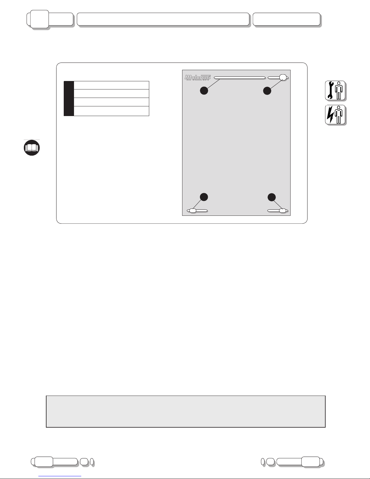
NOTES FOR EASY CONSULTATION
MODIFIED PAGES
• Modied pages shall bear the same number as those in the previous edition,
followed by the letter M, with the new date of issue appearing in the appropriate box.
• Modied pages may contain new illustrations; in this case, the added illustration (or illustrations) will bear the
number of the illustration on the former page, followed by a letter.
ADDITIONAL PAGES
• Any additional pages shall bear the last number of the section to which they belong, followed by the letter A
and the new date of issue.
EDITING SYMBOLS
• Symbols have been provided for quick and easy reference (see page 6), identifying situations requiring
utmost attention or providing practical suggestions or simple information.
• These symbols may appear next to a text (in which case they refer solely to the text itself), next to a gure
(in which case they refer to the topic illustrated in the gure and to the relative text), or at the top of the page
(in which case they refer to all the topics dealt with in the page).
Note:
the meaning of the symbols should be duly memorised as their scope is to avoid having to repeat basic technical
concepts or safety recommendations. They are therefore to be considered as veritable “memory tags”. In case
of any doubt as to their meaning, consult the page in which they are fully described.
W
Z
Y
X
Y Chapter
X Section title
W Page N°
Z Date of issue
(RIGHT HAND PAGE)
PAGE LAYOUT
Page 5
02.07 5
F12R L.C. 50 cc.
Introduction
B
CHAPTER
ISSUE PAGE
R
M
L
H
F
A
B
D
C
I
G
E
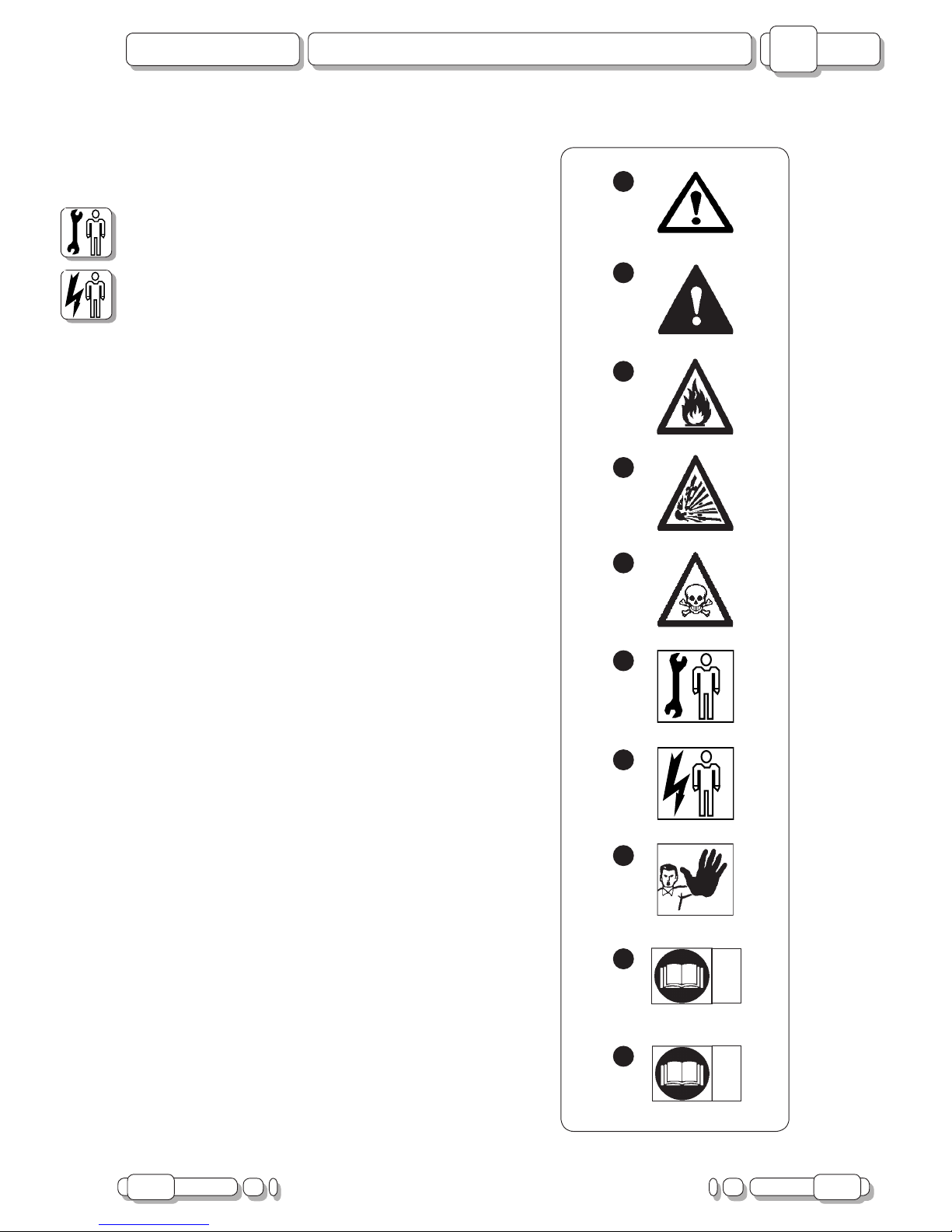
A) CAUTION! Recommendations and precautions
regarding rider safety and motor vehicle integrity.
B) WARNING! Situations entailing the risk of personal
injury to maintenance or repair mechanics, other
workshop personnel or third parties, or damage to
environment, vehicle or equipment.
C) FIRE HAZARD
Indicates operations which may constitute a fire
hazard.
D) RISK OF EXPLOSION
Indicates operations which may constitute a risk of
explosion.
E) TOXIC FUMES
Indicates a possibility of intoxication or inammation
of the upper respiratory tract.
F) MECHANICAL MAINTENANCE
Operations t o be performed only by an expert
mechanic.
G) ELECTRICAL MAINTENANCE
Operations be performed only by an expert electrical/
electronic technician
H) NO! Operations to be absolutely avoided
I) ENGINE SERVICE MANUAL
Indicates information which may be obtained by
referring to said manual.
L) SPARE PARTS CATALOGUE
Indicates information which may be obtained by
referring to said catalogue
Page 6
6 02.07
B
F12R L.C. 50 cc.
Introduction
CHAPTER
PAGE ISSUE
ABBREVIATIONS
A
F Figure
Cs Tightening torque
P Page
Pr Paragraph
S Section
Sc Diagram
T Table
V Screw
Note:
the letter V in the illustrations refers to retaining or adjusting screws. The number following this letter refers to
the number of the same type of screw in the unit or component described and illustrated. Letters not followed
by a number indicate a single screw. In case of different screws being referred to in the illustration, the letter
V is followed by a number and a small letter, for instance: (V4a).
Unless otherwise specied, units and components are reassembled by proceeding in the reverse order of
removal.
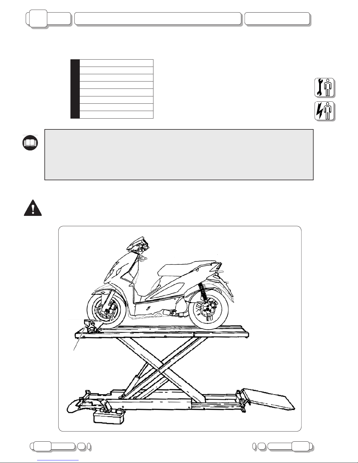
Before any servicing, make sure that the vehicle is perfectly stable.
The front wheel should preferably be anchored to the equipment integral with the lifting board.
Page 7
02.07 7
F12R L.C. 50 cc.
Electrical Components
B
CHAPTER
ISSUE PAGE
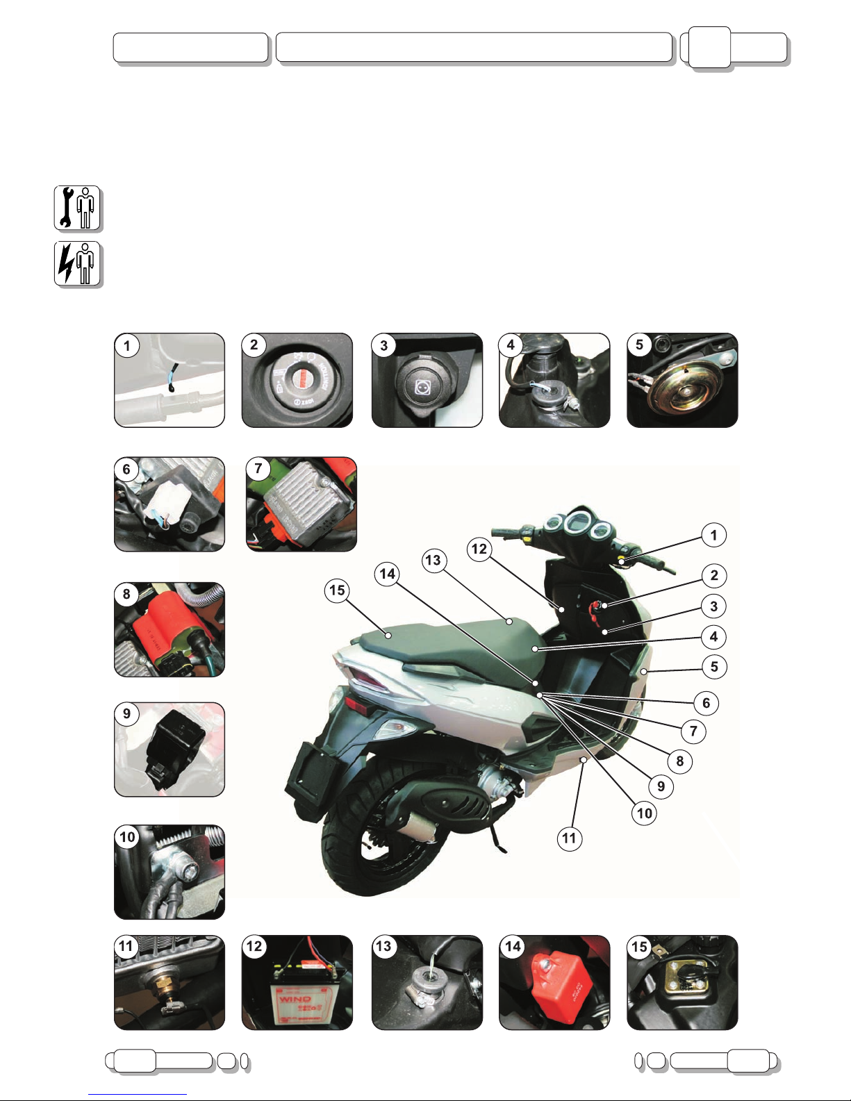
ELECTRICAL COMPONENTS
1) AMBIENT TEMPERATURE PROBE
2) KEY SWITCH
3) RECHARGING SOCKET
4) OIL INDICATOR SWITCH
5) HORN
6) FLASHLIGHT
7) VOLTAGE REGULATOR
8) “CDI” CONTROL UNIT
9) STARTING RELAY
10) GROUNDING WIRE TERMINALS
11) H
2
O TEMPERATURE SENSOR
12) BATTERY
13) FUEL RESERVE SWITCH
14) CHOKE CONTROL
15) FUEL LEVEL SENSOR
Page 8
8 02.07
B
F12R L.C. 50 cc.
General Wiring Diagram
CHAPTER
PAGE ISSUE
ON
0FF
ON
0FF
N
N
N
VL
N
VR
VR
VL
AR
N
N
B-R
VR
VR
VL
VR
B
GL
R
AR
HORN
R
L
TURN
N
START
BL
N
BL
B-R
R
+
-
VL
RS
R
N
VR
M
R
BL
BL
R
BL
VL
VR
PREDISPOSIZIONE
ALLARME
N
N
BL
B
N
N-
R
1
2
3
4
5
6
7
8
9
10
11
12
24
23
22
21 20
19
18
17
16
15
14
13
10
W
10
W
10
W
35
W
35
W
10
W
OFF
ON
N
BL
GL
-B
BL
-R
VR
-N
BL
-N
ON
0FF
BL
MODE
VL
AR
N
VL
RS
RS
BL
N
VR
VL
AZ
M-
N
M-
N
GR-RGR
-R
N
N
B-R
BL
GL-BL
GL
-B
GL
-B
N
AZ
BL
BL
-R
BL
-R
BL
-R
BL
-R
N
R
AZ
BL
RS
R
R-
VR
N-R
N
N
BL
B-
VL
N
B-
VR
GR
N
GL
GL-R
M-
N
N
N
NN
N
VR
VL
R
RS
10
A
7.5
A
RS
RS
RS
N-R
BL
GL
-B
L
B-
VL
BL
-R
B
GR
-R
VL
N
GR
B-
VR
BL
-V
R
RS
RS
RS
N
N
BL
-N
VR
-N
VR
N
N
5 A
N-
R
GL
+
M-
N
AR
AZ
N
BL
-R
B-
VL
BL
VR
N
BL
BL
-V
R
VR
N-R
N
GR
-R
B-R
A
AB
B
AZ
BL
-R
Inte
rr
uttore
spia
olio
m
ix.
Inter
r
uttore
riser
va
carburante
Sonda
livello
carburante
MODE
Signal
rinvio
Alim
. 5
V
Alim
.
12V
V
.bat.
Alim
.
12V
sotto
chiave.
Sensore
temperatura
acqua.
Run STOP
Pick UP
Uscita ricarica / luci
A
lim
.
Centralin
a
<
>
>
>
>
>
>
>
>
>
>
>
>
>
>
>
Imp. Luci / starter
<
>>>
<
>
>
>
>
<
>
BL
-R
GR
-R
GR
B-
VR
B
GL
-BL
BL
-V
R
N
BL
B-
VL
RS
RS
RS
VR
VL
N-R
H8 H8
1
2
3
4
5
6
7
8
9
10
11
12 13
14
15
16
17
18
19
20
21
22
23
24
25
26
27
28
29
30
31
32
Page 9
02.07 9
F12R L.C. 50 cc.
General Wiring Diagram
B
CHAPTER
ISSUE PAGE
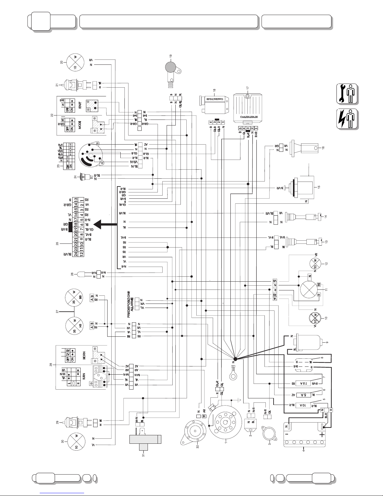
GENERAL WIRING DIAGRAM
GL-B YELLOW/WHITE
GL-V YELLOW/GREEN
GL-R YELLOW/RED
GR GREY
M BROWN
M-N BROWN/BLACK
M-B BROWN/WHITE
N BLACK
N-R BLACK/RED
R RED
R-VR RED/GREEN
RS PINK
VL PURPLE
VR GREEN
KEY TO GENERAL WIRING DIAGRAM
1) FLYWHEEL MAGNETO
2) CHOKE CONTROL
3) ELECTRICAL STARTER
4) BATTERY
5) FUSE, 10 A
6) FUSE, 5 A
7) FUSE, 7.5 A
8) STARTING RELAY
9) STARTER MOTOR
10) REAR LEFT TURN INDICATOR
11) 5W PARKING LIGHT / 10W STOP LIGHT
12) REAR RIGHT TURN INDICATOR
13) OIL INDICATOR SWITCH
14) FUEL RESERVE SWITCH
15) H
2
O TEMPERATURE SENSOR
16) FUEL LEVEL SENSOR
COLOUR KEY
AR ORANGE
AR-BL ORANGE/BLUE
R-VR RED/GREEN
AZ LIGHT BLUE
B WHITE
B-VL WHITE/PURPLE
B-VR WHITE/GREEN
B-VL WHITE/PURPLE
B-BL WHITE/BLUE
B-R WHITE/RED
BL BLUE
BL-R BLUE/RED
BL-VR BLUE/GREEN
GL YELLOW
GL-BL YELLOW/BLUE
17) VOLTAGE REGULATOR
18) “CDI” CONTROL UNIT
19) SENSOR TRANSMISSION
20) FRONT LEFT TURN INDICATOR
21) FRONT STOP SWITCH
22) RIGHT HAND SWITCH
23) KEY SWITCH
24) RECHARGING SOCKET
25) INSTRUMENT BOARD
26) AMBIENT TEMPERATURE PROBE
27) DOUBLE HEADLIGHT
28) LEFT SWITCH
29) REAR STOP SWITCH
30) FRONT LEFT TURN INDICATOR
31) FLASHLIGHT
32) HORN
Page 10
10 02.07
B
F12R L.C. 50 cc.
Checking Switches
CHAPTER
PAGE ISSUE
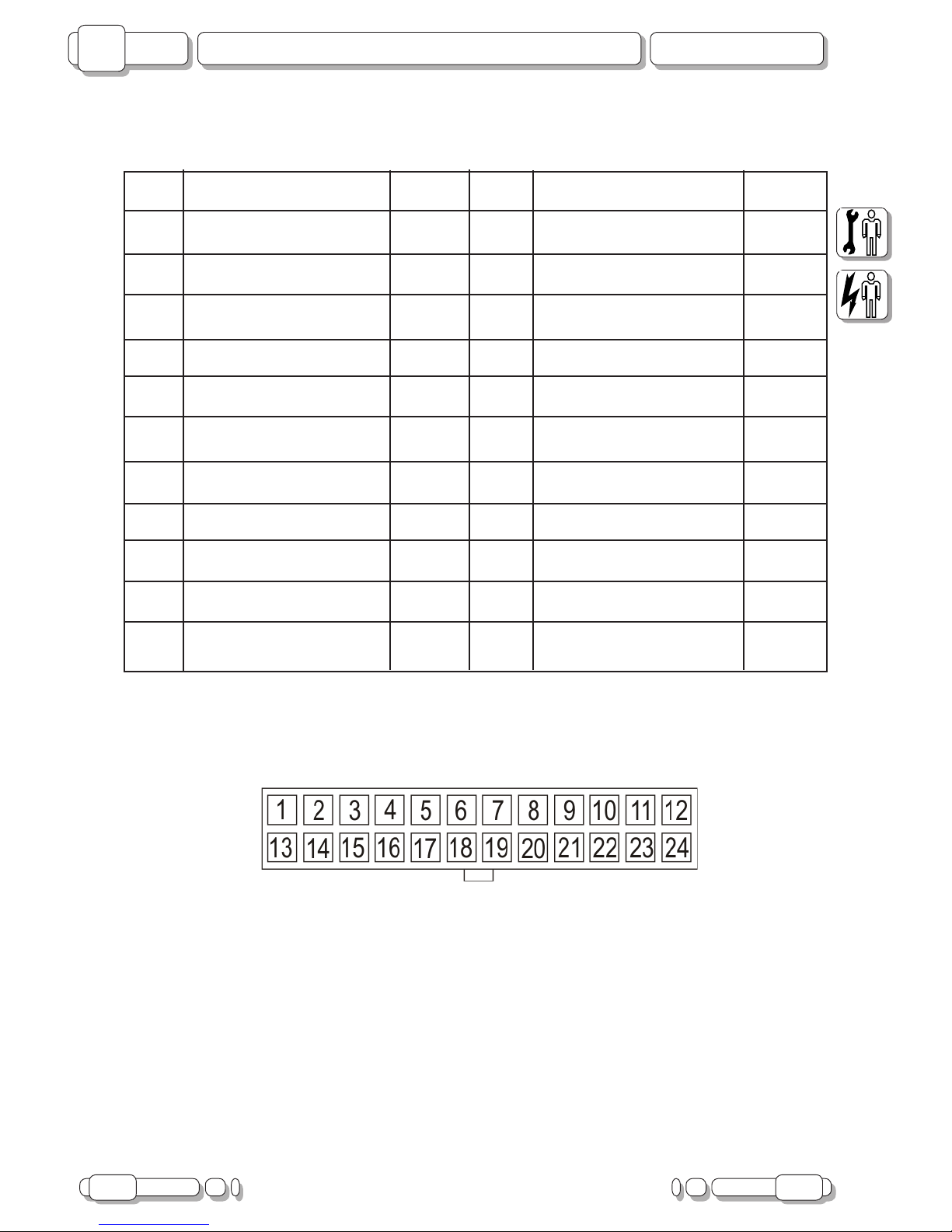
INSTRUMENT BOARD CONNECTOR CONFIGURATION
1) RPM RS
2) RIGHT TURN INDICATOR VR
3) LIGHT INDICATOR RS
4) BACKLIGHTING RS
5) AMBIENT TEMPERATURE N-R
6) KEY ACTIVATION (+12V) BL
7) VDC HALL SENSOR (+5V) GL-BL
8) MIXTURE OIL B-VL
9) BATTERY POSITIVE BL-R
10) - -
11) - -
12) - -
13) HALL SENSOR SIGNAL B
14) MODE BUTTON GR-R
15) - -
16) LEFT TURN INDICATOR VL
17) GND (-) N
18) FUEL PROBE GR
19) WTEMP RESIST. PROBE B/VR
20) - -
21) - -
22) - -
23) - -
24) FUEL RES. WARNING LIGHT BL-VR
24 PIN
Page 11
02.07 11
F12R L.C. 50 cc.
Checking Switches
B
CHAPTER
ISSUE PAGE
F. 1
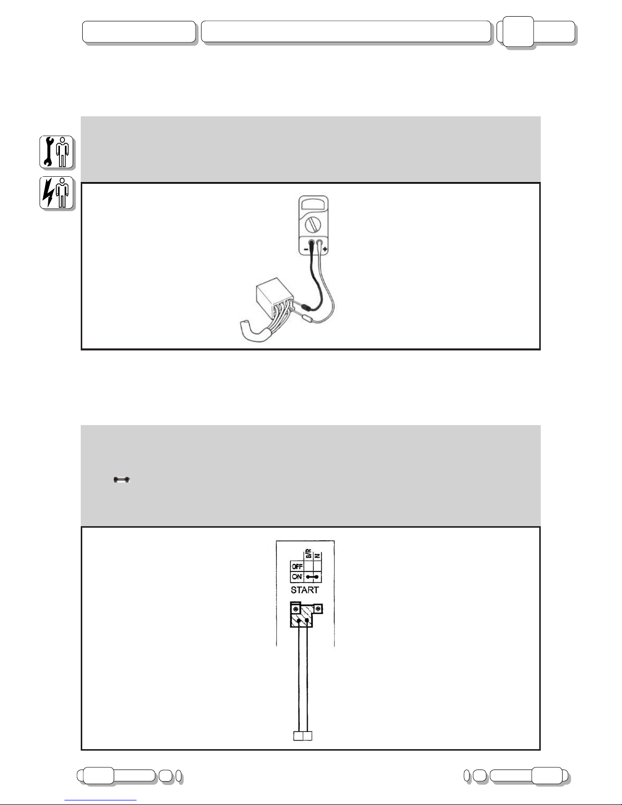
CHECKING SWITCHES
CHECKING PROCEDURES
- Using a Tester (code n°08609500), check switches. In particular, check continuity between terminals to
make sure they are correctly connected.
- Replace the switch, even if only one of the possible combinations does not give the requested result.
Set the tester to function Ω.
F. 2
CONNECTION OF SWITCHES DESCRIBED IN THIS MANUAL
- This manual contains connection diagrams, like the one illustrated hereby, which illustrate how switch
terminals should be connected (key switch, brake switch, “Mode” button, etc.).
- The rst column from the left indicates the different positions of the switch, the top line the colour of the
wires connected to the switch terminals.
- The “ ” symbol identies terminals in which there is a condition of continuity, i.e. a closed circuit, in a
certain position of the switch.
- In this diagram:
- “B/R” and “N” there is continuous contact when the switch is “ON”.
Page 12
12 02.07
B
F12R L.C. 50 cc.
Checking Switches
CHAPTER
PAGE ISSUE
1
2
3
4
5
6
7
7
1
2
3
4
5
6
R
BL
R
L
VR
VL
M-
N
ON
0FF
AR
AZ
R
BL
ON
0FF
BL
GR
-R
ON
0FF
N
B-R
OFF
ON
N
BL
GL
-B
BL
-R
VR
-N
BL
-N
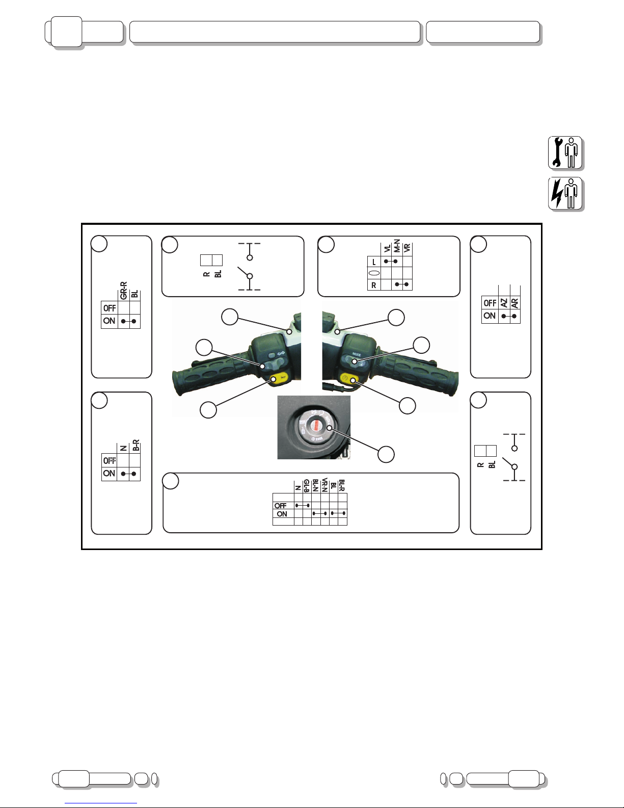
POSITION OF SWITCHES AND CONNECTION OF CONNECTORS
1) REAR STOP SWITCH
2) TURN INDICATOR SWITCH
3) HORN CONTROL
4) FRONT STOP SWITCH
5) “MODE” BUTTON SWITCH
6) START SWITCH
7) KEY SWITCH
NOTE: the start switch is closed when the START button is pressed.
The STOP switch is closed when the brake lever is operated.
Page 13
02.07 13
F12R L.C. 50 cc.
Fuses
B
CHAPTER
ISSUE PAGE
C
B
A
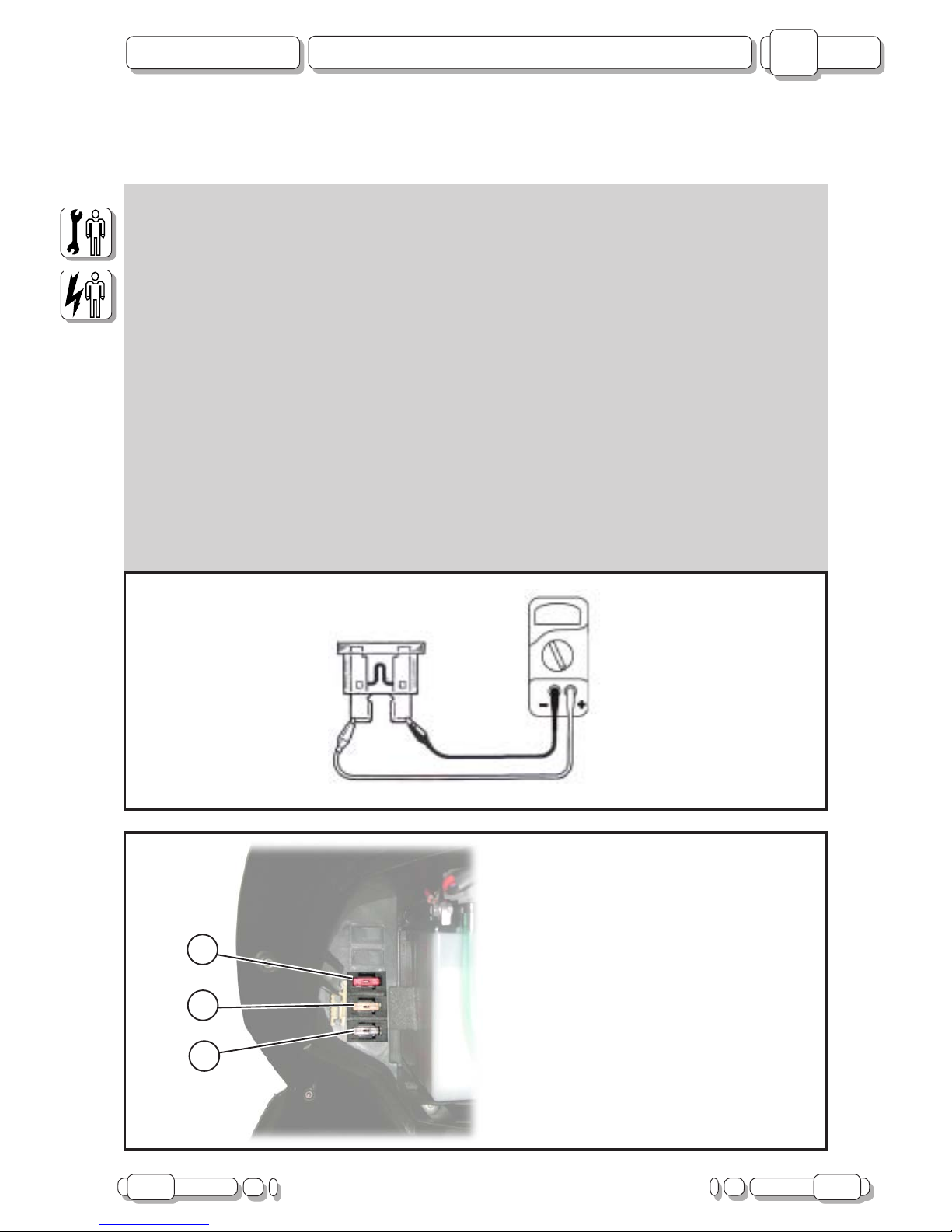
A) 10A Main / Recharging
B) 5A Stop / Turn indicators / Horn
C) 7.5A Lights / Starter
FUSES
CHECKING FUSES
CAUTION: when checking fuses, always turn the main switch “OFF” or short-circuits may occur.
Checking procedure:
- Connect Tester (code n°08609500) to fuse and check continuity.
NOTE: put the Tester on “Ω” (sound-emitting function).
- If the tester is showing “I” and no sound is given, replace the fuse.
Replacing procedure:
- Turn key “OFF”.
- Fit a new fuse with a correct amperage rating.
- Turn key “ON”.
- Turn switches on to check operation of the relative electrical systems.
- If the fuse blows again, check the relative circuit.
CAUTION: never use fuses with an amperage rating differing from that indicated. Use only fuses and
never other materials.
An unsuitable fuse can cause extensive damage to the electrical system, malfunctioning of the ignition
and light systems and even res to break out.
F. 3
F. 4
Page 14
14 02.07
B
F12R L.C. 50 cc.
Starting System
CHAPTER
PAGE ISSUE
IGNITION SYSTEM
If the ignition system is not working, check:
1) CONDITION OF SPARK PLUG
2) SPARK PLUG CAP RESISTANCE
3) RESISTANCE OF “CDI” CONTROL UNIT
4) RESISTANCE OF START PICK-UP
5) CONTINUITY OF KEY SWITCH
6) CONNECTIONS OF IGNITION SYSTEM
2
1
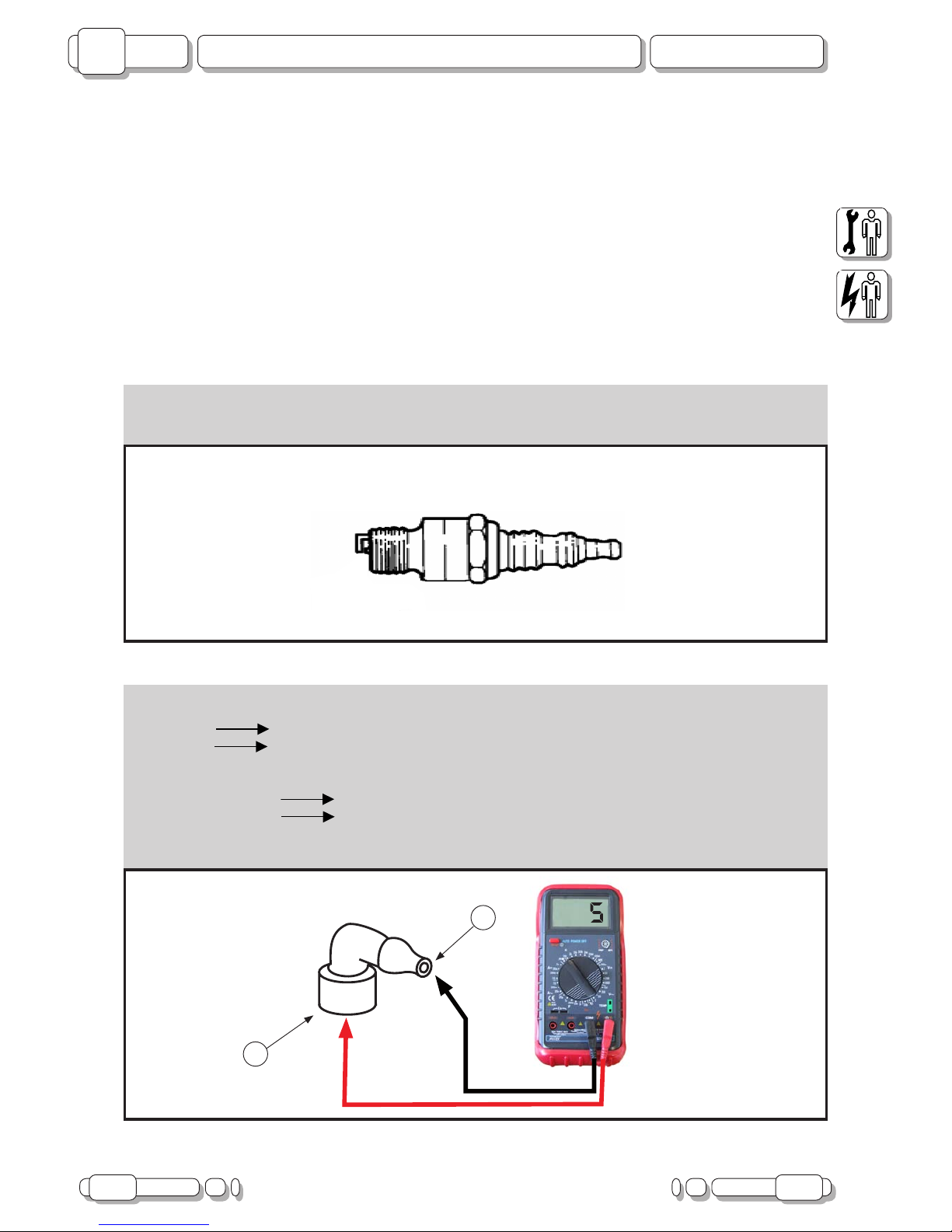
2. Spark plug cap resistance
- Remove spark plug cap.
- NOTE: when removing spark plug cap, do not pull.
- To remove
turn anti-clockwise.
- To connect
turn clockwise.
- Before connecting the spark plug cap, check the HV cable and cut off a piece of approximately 5 mm.
- Connect Tester (KΩ) to spark plug cap, as follows:
- Terminal (+) of Tester
Spark plug side (1).
- Terminal (-) of Tester
High voltage cable side (2).
- Spark plug cap resistance: 5 KΩ at 20°C.
- Not compliant: replace spark plug cap.
1. Condition of spark plug
- Check condition of spark plug.
- See Engine Workshop Manual.
- Not compliant: replace spark plug.
F. 5
F. 6
Tester (kΩ)
Page 15

02.07 15
F12R L.C. 50 cc.
Starting System
B
CHAPTER
ISSUE PAGE
3. Resistance of “CDI” control unit (red)
- Connect Tester (2kΩ) to “CDI”, as follows:
- Terminal (+) of Tester
HV screw (V).
- Terminal (-) of Tester
PIN 1 (GND).
- Resistance: 525 ÷ 640 Ω at 20°C (F.7a).
- Terminal (+) of Tester
PIN 1 (GND).
- Terminal (-) of Tester
PIN 2 (PICK-UP).
- Resistance: 335 ÷ 385 Ω at 20°C (F.7b).
- Not compliant: Replace “CDI” control unit (code n° 02411000).
4. Stator pick-up resistance
- Remove two-way connector of wiring.
- Connect Tester (Ω) to connector of ywheel magneto (V).
- Terminal (+) of Tester
Red cable (1).
- Terminal (-) of Tester
Ground (2).
- Stator pick-up resistance: 195 ÷ 205 Ω at 20°C.
- Not compliant: replace stator.
F. 7a
1
V
1
2
1
F. 7b
GL
R
F. 8
2
V
Tester (2kΩ) Tester (2kΩ)
Tester (Ω)
Page 16

16 02.07
B
F12R L.C. 50 cc.
Starting System
CHAPTER
PAGE ISSUE
6. Connections of ignition system
- Check connections of ignition system.
- NOTE: pay attention to correctly insert cables into connector (C) of “CD1” control unit.
- Not compliant: resume connections of ignition system.
See "Wiring Diagram”.
5. Continuity of key switch
- Disconnect key switch from system.
- Connect Tester (Ω) as follows:
- Terminal (+) of Tester
Yellow/white cable (1).
- Terminal (-) of Tester
Black cable (2).
- Turn key “OFF” and then “ON”.
- Check continuity of key switch.
- Not compliant: replace key switch.
see “Checking switches” on page 11
F. 9
OFF
ON
N
BL
GL
-B
BL
-R
VR
-N
BL
-N
1
2
C
F. 10
1
2
3
4
POS. CABLE DESTINATION
1 GND (N)
2 PICK-UP (GL/R)
3 ENGINE STOP (GL/B)
4 REGULATOR (B)
Tester (Ω)
Page 17

02.07 17
F12R L.C. 50 cc.
Ignition System
B
CHAPTER
ISSUE PAGE
STARTING SYSTEM
If the starting system is not working, check:
1) CONTINUITY OF 10A / 5A FUSE
2) CONDITION OF BATTERY
3) OPERATION OF STARTER MOTOR
4) OPERATION OF STARTING RELAY
5) KEY SWITCH
6) FRONT/REAR STOP SWITCH
7) START SWITCH (START)
8) CONNECTION OF STARTING SYSTEM
1. Continuity of 10A / 5A fuse
- Remove fuse.
- Connect Tester (Ω) to fuse.
- Check continuity of fuse.
- Not compliant: replace fuse.
2. Condition of battery
- Check condition of battery.
- Minimum voltage: 12.5 V.
- Density of electrolytic solution: 1.280 g/dm
3
- Not compliant: clean terminals.
Recharge or replace battery.
F. 11
F. 12
BATTERIA
+
-
12
V
5Ah
Tester (Ω)
Page 18

18 02.07
B
F12R L.C. 50 cc.
Ignition System
CHAPTER
PAGE ISSUE
3. Starter motor
- Use a bridge cable (3) to connect the positive battery terminal (1) to the cable of the starter motor (2), as
shown in the gure.
WARNING: for the bridge, use a cable that can withstand the power draw of the starter motor otherwise
it would burn out.
- Check operation of the starter motor.
- Not compliant: replace starter motor.
4. Starting relay
- Connect the battery to the terminals of the starting relay (4) using bridge cables (1), as follows:
- (+) cable of battery
Red cable.
- (-) cable of battery
Red/white cable.
CAUTION: never invert battery connections.
When connecting the battery to the relay, avoid triggering short-circuits between the
positive and negative terminals.
- Check operation of the starter motor.
- Not compliant: replace starting relay.
F. 13
1
2
3
F. 14
1
B-R
R
RBL
R
B-R
R
BL
4
Page 19

02.07 19
F12R L.C. 50 cc.
Ignition System
B
CHAPTER
ISSUE PAGE
5. Key switch
- Disconnect key switch from system.
- Connect Tester (Ω) as follows:
- Terminal (+) of Tester
Blue/Red cable (1).
- Terminal (-) of Tester
Blue cable (2).
- Turn key “OFF” and then “ON”.
- Check continuity of key switch.
- Not compliant: replace key switch.
see “Checking switches” on page 11
6. Front/rear stop switch
- Disconnect switch cables (A).
- Connect Tester (Ω) to terminals (T1-T2).
- Check continuity between terminals.
- Not compliant: replace stop switch.
See “Checking switches” on page 11
F. 15
OFF
ON
N
BL
GL
-B
BL
-R
VR
-N
BL
-N
F. 16
A
T.1 T.2
1
2
1) Front or rear brake lever
pulled
2) Front or rear brake lever
not pulled
Tester (Ω)
Tester (Ω)
1
2
Page 20

20 02.07
B
F12R L.C. 50 cc.
Ignition System
CHAPTER
PAGE ISSUE
7. Start switch (START)
- Detach four-way connector of right hand switch.
- Connect Tester (Ω) to connector, as follows:
- Terminal (+) of Tester
White/red cable (1).
- Terminal (-) of Tester
Black cable (2).
- Press “START” button.
- Check continuity.
- Not compliant: replace right hand switch.
8. Connections of starting system
- Check connections of starting system.
- Not compliant: resume connections of starting system.
See “Wiring Diagram”.
ON
0FF
N
START
ON
0FF
BL
MODE
GR
-R
N
B-R
BL
GR
-R
B-R
F. 17
Tester (Ω)
2
1
Page 21

02.07 21
F12R L.C. 50 cc.
Charging System
B
CHAPTER
ISSUE PAGE
CHARGING SYSTEM
If the charging system is not working, check:
1) CONTINUITY OF 10A FUSE
2) BATTERY CHARGING VOLTAGE
3) CHARGING COIL RESISTANCE
4) CONNECTIONS OF RECHARGING SYSTEM
1. Continuity of 10A fuse
- Remove fuse.
- Connect Tester (Ω) to fuse.
- Check continuity of fuse.
- Not compliant: replace fuse.
2. Battery charging voltage
- Connect inductive rev counter to spark plug cable
- Connect Tester (20 VDC) to battery, as follows:
- Terminal (+) of Tester
(+) terminal of battery (1).
- Terminal (-) of Tester
(-) terminal of battery (2).
- Start engine and run it at 5000 RPM.
- Check battery voltage.
- Charging voltage: 13.5 ~ 14.5 V.
- Not compliant: continue searching.
- NOTE: use a fully charged battery.
F. 18
BATTERIA
+
-
12
V
5Ah
2
1
F. 19
Tester (Ω)
Tester (DC 20 V)
Page 22

22 02.07
B
F12R L.C. 50 cc.
Charging System
CHAPTER
PAGE ISSUE
3. Charging coil resistance
- Detach connector of ywheel magneto.
- Connect Tester (Ω), as follows:
- Terminal (+) of Tester
Yellow cable (1).
- Terminal (-) of Tester
Ground (2).
- Charging coil resistance: 1 ÷ 1.2 Ω at 20°C.
- Not compliant: replace stator.
4. Connections of recharging system
- Check connections of recharging system.
- Compliant: replace voltage regulator (code n° 02602600).
- Not compliant: resume connections of recharging system.
See “Wiring Diagram”.
1
GL
R
2
F. 20
Tester (Ω)
Page 23

02.07 23
F12R L.C. 50 cc.
Lighting System
B
CHAPTER
ISSUE PAGE
LIGHTING SYSTEM
If the lighting system is not working, check:
1) CONTINUITY OF 7.5A FUSE
2) RESISTANCE OF LIGHTING SYSTEM COIL
3) CONTINUITY OF YELLOW CABLE
4) VOLTAGE REGULATOR
5) CONNECTION OF LIGHTING SYSTEM
1. Continuity of 7.5A fuse
- Remove fuse.
- Connect Tester (Ω) to fuse.
- Check continuity of fuse.
- Not compliant: replace fuse.
2. Lighting system coil resistance
- Detach connector of ywheel magneto.
- Connect Tester (Ω), as follows:
- Terminal (+) of Tester
Yellow cable (1).
- Terminal (-) of Tester
Ground (2).
- Lighting system coil resistance: 1 ÷ 1.2 Ω at 20°C.
- Compliant: continue searching.
- Not compliant: replace stator.
F. 21
GL
R
F. 22
Tester (Ω)
Tester (Ω)
1
2
Page 24

24 02.07
B
F12R L.C. 50 cc.
Lighting System
CHAPTER
PAGE ISSUE
3. Continuity of yellow cable
- Connect connector of ywheel.
- Disconnect regulator connector.
- Connect Tester (Ω), as follows:
- Terminal (+) of Tester
Yellow cable (1).
- Terminal (-) of Tester
Black cable (2).
- Resistance: 1 ÷ 1.2 Ω at 20°C.
- Not compliant: yellow cable interrupted between ywheel connector and regulator connector. Repair.
See “Wiring Diagram”.
4. Voltage regulator
- Connect Tester (20 V AC) to connector of regulator (leaving it plugged in), as follows:
- Terminal (+) of Tester
Red/green cable (1).
- Terminal (-) of Tester
Black cable (2).
- Run engine at 5000 RPM.
- Voltage: > 12 V.
- Not compliant: replace voltage regulator (code n° 02602600).
5. Connections of lighting system
- Check connections of lighting system.
- Not compliant: resume connections of lighting system.
See “Wiring Diagram”.
BL-R
N
B
R-
VR
GL
1
2
F. 23
BL-R
N
B
R-
VR
GL
2
1
F. 24
Tester (Ω)
Tester (AC 20 V)
Page 25

02.07 25
F12R L.C. 50 cc.
Lighting System
B
CHAPTER
ISSUE PAGE
If the headlight is not working, check:
1) CONTINUITY OF LIGHT BULB AND RELATIVE COUPLING
2) VOLTAGE DELIVERED TO LAMP SOCKET
2. Voltage delivered to lamp socket
- Connect Tester (20 V AC) to connector of headlight, as follows:
- Terminal (+) of Tester
Pink cable (1).
- Terminal (-) of Tester
Black cable (2).
- Run engine at 5000 RPM.
- Voltage delivered to lamp socket: > 12 V.
- Not compliant: pink cable is interrupted. Repair.
See “Wiring Diagram”.
N
35
W
35
W
RS
RS
N
A
AB
B
H8 H8
F. 25
1 2
1. Continuity of light bulb and relative coupling
- Remove light bulb.
- Connect Tester (Ω) to light bulb.
- Check continuity of light bulb.
- Not compliant: replace light bulb.
Tester (AC 20 V)
Page 26

26 02.07
B
F12R L.C. 50 cc.
Lighting System
CHAPTER
PAGE ISSUE
If the instrument board indicator lights are not working, check:
1) VOLTAGE DELIVERED TO INSTRUMENT BOARD
F. 26
1
2
3
4
5
6
7
8
9
10
11
12
24
23
22
21
20
19
18
17
16
15
14
13
RS
RS
RS
N-R
BL
GL
-BL
B-
VL
BL
-R
B
GR
-R
VL
N
GR
B-
VR
BL
-V
R
VR
PIN 17
PIN 3
Tester (AC 20 V)
1. Voltage delivered to instrument board
- Connect Tester (20 V AC) to instrument board connector, as follows:
- Terminal (+) of Tester
Pink cable (PIN 3).
- Terminal (-) of Tester
Black cable (PIN 17).
- Run engine at 5000 RPM.
- Voltage delivered to instrument board: > 12 V.
- Compliant: replace instrument board.
- Not compliant: pink cable is interrupted. Repair.
See “Wiring Diagram”.
- NOTE: if the indicator light does not come on during the “CHECK”, replace the instrument board.
Page 27

02.07 27
F12R L.C. 50 cc.
Lighting System
B
CHAPTER
ISSUE PAGE
If the rear light is not working, check:
1) CONTINUITY OF LAMP
2) VOLTAGE DELIVERED TO LAMP SOCKET
1. Continuity of lamp
- Remove light bulb.
- Connect Tester (Ω) to light bulb.
- Check continuity of lamp.
- Not compliant: replace lamp.
2. Voltage delivered to lamp socket
- Connect Tester (20 V AC) to connector of headlight, as follows:
- Terminal (+) of Tester
Pink cable (1).
- Terminal (-) of Tester
Black cable (2).
- Run engine at 5000 RPM.
- Voltage delivered to lamp socket: > 12 V.
- Not compliant: pink cable is interrupted. Repair.
See “Wiring Diagram”.
F. 27
1
2
Tester (AC 20 V)
Page 28

28 02.07
B
F12R L.C. 50 cc.
Signalling System
CHAPTER
PAGE ISSUE
SIGNALLING SYSTEM
If the signalling system is not working, check:
1) CONTINUITY OF 10 A FUSE
2) CONDITION OF BATTERY
3) KEY SWITCH
4) CONNECTIONS OF SIGNALLING SYSTEM
1. Continuity of 10A fuse
- Remove fuse.
- Connect Tester (Ω) to fuse.
- Check continuity of fuse.
- Not compliant: replace fuse.
2. Condition of battery
- Check condition of battery.
- Minimum voltage: 12.5 V.
- Density of electrolytic solution: 1.280 g/dm
3
- Not compliant: clean terminals.
Recharge or replace battery.
F. 28
BATTERIA
+
-
12
V
5Ah
F. 29
Tester (Ω)
Page 29

02.07 29
F12R L.C. 50 cc.
Signalling System
B
CHAPTER
ISSUE PAGE
3. Key switch
- Disconnect key switch from system.
- Turn key “ON”
- Connect Tester (Ω), as follows:
- Terminal (+) of Tester
Blue/Red cable (1).
- Terminal (-) of Tester
Blue cable (2).
- Check continuity of key switch.
- Not compliant: replace key switch.
See “Checking switches” on page 11
4. Connections of signalling system
- Check connections of signalling system.
- Not compliant: resume connections of signalling system.
See “Wiring Diagram”.
F. 30
OFF
ON
N
BL
GL
-B
BL
-R
VR
-N
BL
-N
1
2
Tester (Ω)
Page 30

30 02.07
B
F12R L.C. 50 cc.
Signalling System
CHAPTER
PAGE ISSUE
If the horn is not working, check:
1) HORN SWITCH
2) VOLTAGE DELIVERED TO HORN
3) GROUNDING OF HORN
1. Horn switch
- Disconnect six-way connector of left hand switch.
- Press Horn button to activate horn.
- Connect Tester (Ω) to connector, as follows:
- Terminal (+) of Tester
Orange cable (1).
- Terminal (-) of Tester
Light blue cable (2).
- Check continuity of switch (with button pressed).
- Not compliant: replace left hand switch.
2. Voltage delivered to horn
- Connect Tester (20 V DC) to horn, as follows:
- Terminal (+) of Tester
Orange cable (1).
- Terminal (-) of Tester
Chassis grounding (2).
- Turn key “ON”.
- Press Horn button.
- Voltage delivered to horn: > 12 V.
- Not compliant: resume connections of horn power supply circuit.
See “Wiring Diagram”.
ON
0FF
VR
HORN
R
L
TURN
VL
AR
VR
VL
M-
N
M-
N
AR
AZ
AZ
F. 31
AR
N
+
1
2
F. 32
2
1
Tester (Ω)
Tester (DC 20 V)
Page 31

02.07 31
F12R L.C. 50 cc.
Signalling System
B
CHAPTER
ISSUE PAGE
3. Grounding of horn
- Disconnect black cable from terminal of horn.
- Connect a bridge cable (1) between terminal (2) and grounding point of chassis (3).
- Turn key “ON”.
- Press Horn button to activate horn.
- Compliant: resume connection between black cable and chassis grounding.
See “Wiring Diagram”.
- Not compliant: replace horn.
IIf stop light is not working, check:
1) CONTINUITY OF 5 A FUSE
2) CONTINUITY OF LIGHT BULB AND RELATIVE COUPLING
3) FRONT AND REAR BRAKE SWITCH
4) VOLTAGE DELIVERED TO LIGHT BULB COUPLING
1. Continuity of 5A fuse
- Remove fuse.
- Connect Tester (Ω) to fuse.
- Check continuity of fuse.
- Not compliant: replace fuse
- NOTE: if 5A fuse is not compliant, the ashlight will not be working.2.
F. 33
AR
N
+
3
1
2
F. 34
Tester (Ω)
Page 32

32 02.07
B
F12R L.C. 50 cc.
Signalling System
CHAPTER
PAGE ISSUE
2. Continuity of light bulb and relative coupling
- Remove light bulb.
- Connect Tester (Ω) to light bulb.
- Check continuity of light bulb and its coupling.
- Not compliant: replace light bulb or coupling.
3. Front and rear brake switch
- Disconnect switch cables (A).
- Connect Tester (Ω) to terminals (T1-T2).
- Check continuity between terminals.
- Not compliant: replace stop switch.
See “Checking switches” on page 11
4. Voltage delivered to light bulb coupling
- Connect Tester (20 V DC) to connector of light bulb coupling, as follows:
- Terminal (+) of Tester
Red cable (1).
- Terminal (-) of Tester
Black cable (2).
- Turn key “ON”.
- Pull front or rear brake lever
- Voltage delivered to light bulb coupling: > 12 V.
- Not compliant: red cable interrupted. Resume connection.
See “Wiring Diagram”.
- NOTE: if the grounding connection is interrupted, the rear light will not be working.
F. 35
T.1 T.2
1
2
1) Front or rear brake lever
pulled
2) Front or rear brake lever
not pulled
F. 36
1
2
A
Tester (Ω)
Tester (DC 20 V)
Page 33

02.07 33
F12R L.C. 50 cc.
Signalling System
B
CHAPTER
ISSUE PAGE
If the turn indicators and the relative indicator lights are not working, check:
1) CONTINUITY OF 5 A FUSE
2) TURN INDICATOR SWITCH
3) VOLTAGE DELIVERED TO FLASHLIGHT
4) CONTINUITY OF BROWN/BLACK CABLE
1. 5 A fuse
- Remove fuse.
- Connect Tester (Ω) to fuse.
- Check continuity of fuse.
- Not compliant: replace fuse.
2. Turn indicator switch
- Disconnect six-way connector of left hand switch.
- Connect Tester (Ω) to cables, as follows:
- Activate right turn indicators:
- Terminal (+) of Tester
Brown/Black cable (1).
- Terminal (-) of Tester
Green cable (2).
- Activate left turn indicators:
- Terminal (+) of Tester
Brown/Black cable (1).
- Terminal (-) of Tester
Purple cable (3).
- There must be continuity in both cases.
- Not compliant: replace left hand switch.
F. 37
ON
0FF
VR
HORN
R
L
TURN
VL
AR
VR
VL
M-
N
M-
N
AR
AZ
AZ
F. 38a
1
3
ON
0FF
VR
HORN
R
L
TURN
VL
AR
VR
VL
M-
N
M-
N
AR
AZ
AZ
1
2
F. 38b
Tester (Ω)
Tester (Ω) Tester (Ω)
Page 34

34 02.07
B
F12R L.C. 50 cc.
Signalling System
CHAPTER
PAGE ISSUE
3. Voltage delivered to ashlight
- Detach ashlight connector.
- Connect Tester (20 V DC), as follows:
- Terminal (+) of Tester
Blue cable (1).
- Terminal (-) of Tester
Chassis grounding (2).
- Turn key “ON”.
- Voltage delivered to ashlight: > 12 V.
- Not compliant: blue cable interrupted. Repair.
See “Wiring Diagram”.
4. Continuity of brown/black cable
- Detach ashlight connector.
- Disconnect left hand switch connector.
- Connect Tester (Ω) to terminals of respective connectors.
- Check continuity of brown/black cable
- Compliant: replace ashlight.
- Not compliant: brown/black cable between ashlight and left hand switch interrupted. Repair.
See “Wiring Diagram”.
F. 40
1
2
F. 39
M
BL
M-
N
M
BL
M-
N
ON
0FF
VR
HORN
R
L
TURN
VL
AR
VR
VL
M-
N
M-
N
AR
AZ
AZ
Tester (DC 20 V)
Tester (Ω)
Page 35

02.07 35
F12R L.C. 50 cc.
Signalling System
B
CHAPTER
ISSUE PAGE
If right or left turn indicators are not working, check:
1) CONTINUITY OF LIGHT BULB AND RELATIVE COUPLING
2) VOLTAGE DELIVERED TO RIGHT OR LEFT LAMP SOCKET
1. Continuity of light bulb and relative coupling
- Remove light bulb.
- Connect Tester (Ω) to light bulb.
- Check continuity of light bulb.
- Not compliant: replace light bulb.
See “Checking switches” on page 11
2. Voltage delivered to right or left lamp socket
- Connect Tester (20 V DC) to connector of light bulb coupling, as follows:
- Left turn indicator (A):
- Terminal (+) of tester
Purple cable (1).
- Terminal (-) of Tester
Chassis grounding (2).
- Right turn indicator (B):
- Terminal (+) of Tester
Green cable (3).
- Terminal (-) of Tester
Chassis grounding (4).
- Turn key “ON”.
- Operate switch to activate left turn indicators (A)
- Operate switch to activate right turn indicators (B)
- Voltage delivered to lamp socket: > 12 V.
- Not compliant: resume connection between switch of turn indicators and connector of light bulb coupling.
See “Wiring Diagram”.
F. 41a
4
3
1
F. 41b
N
VL
10
W
N
VR
10
W
2
A B
Tester (DC 20 V) Tester (DC 20 V)
Page 36

36 02.07
B
F12R L.C. 50 cc.
Signalling System
CHAPTER
PAGE ISSUE
If “MODE” button is not working, check:
1) CONTINUITY OF “MODE” BUTTON
2) VOLTAGE DELIVERED TO “MODE” BUTTON
3) CONTINUITY OF GREY/RED CABLE
1. Continuity of “MODE
” button
- Disconnect four-way connector of right hand switch.
- Connect Tester (Ω) to connector, as follows:
- Terminal (+) of Tester
Blue cable (1).
- Terminal (-) of Tester
Grey/red cable (2).
- Press “MODE” button.
- Check continuity.
- Not compliant: replace right hand switch.
ON
0FF
N
START
ON
0FF
BL
MODE
GR
-R
N
B-R
BL
GR
-R
B-R
F. 42
1
2
Tester (Ω)
Page 37

02.07 37
F12R L.C. 50 cc.
Signalling System
B
CHAPTER
ISSUE PAGE
3. Continuity of grey/red cable
- Connect Tester (Ω), as follows:
- Terminal (+) of Tester
Grey/red cable (right hand switch) (1).
- Terminal (-) of Tester
Grey/red cable (PIN 14 of instrument board) (2).
- Compliant: replace digital instrument.
- Not compliant: grey/red cable is interrupted. Repair.
See “Wiring Diagram”.
2
2. Voltage delivered to “MODE” button
- Connect Tester (20 V DC) to connector (system side), as follows:
- Terminal (+) of Tester
Blue cable (1).
- Terminal (-) of Tester
Chassis grounding (2).
- Turn key “ON”.
- Voltage delivered to right hand switch: > 12 V.
- Not compliant: blue cable interrupted. Repair.
See “Wiring Diagram”.
ON
0FF
N
START
ON
0FF
BL
MODE
G
R-
R
N
B-
R
BL
G
R
-R
B-R
F. 43
1
2
Tester (DC 20 V)
ON
0FF
N
START
ON
0FF
BL
MODE
GR
-R
N
B-R
BL
GR
-R
B-R
1
2
3
4
5
6
7
8
9
10
11
12
24
23
22
21
20
19
18
17
16
15
14
13
RS
RS
RS
N-R
BL
GL
-BL
B-
VL
BL
-R
B
GR
-R
VL
N
GR
B-
VR
BL
-V
R
VR
1
Tester (Ω)
F. 44
Page 38

38 02.07
B
F12R L.C. 50 cc.
Signalling System
CHAPTER
PAGE ISSUE
If H2O temperature indicator is not working,
check:
1) RESISTANCE OF H2O TEMPERATURE PROBE
- NOTE: the LED and relative icon on the display will start ashing to signal that the probe is not
connected.
F. 45
1. Resistance of H2O temperature probe
- Measurement of H2O temperature is performed in accordance to the following table:
Liquid temperature alarm
When temperature of liquid reaches its threshold (the last segment of the bar graph comes on), the
relative alarm is activated.
The liquid temperature warning light will come on.
To avoid false alarms, this alarm is activated only if the contact remains grounded for a period of
more than ten seconds.
F. 46
L
H
°C Resistance (Ω) Segments
≤ 30 >2060 0
30 ÷ 39 2059 ÷ 1249 1
40 ÷ 49 1250 ÷ 891 2
50 ÷ 59 890 ÷ 591 3
60 ÷ 79 590 ÷ 281 4
80 ÷ 94 280 ÷ 161 5
95 ÷ 99 160 ÷ 151 6
100 ÷ 104 150 ÷ 134 7
>105 ≤ 133 8
Page 39

02.07 39
F12R L.C. 50 cc.
Signalling System
B
CHAPTER
ISSUE PAGE
If the mixture oil signal
is not correct
, check:
1) OIL PROBE
2) VOLTAGE LEVEL CHECK
1. Oil probe
- Detach connector of oil probe and take it out of tank.
- Connect Tester (Ω) to connector, as follows:
- Terminal (+) of Tester
Coupling (1).
- Terminal (-) of Tester
Coupling (2).
- Check continuity of oat (A). In there is continuity, the oat will move freely and position itself at the base
of the probe.
- Not compliant: replace oil probe.
F. 47
2. Check voltage level
- Connect Tester (20 V DC) to connector (system side), as follows:
- Terminal (+) of Tester
Blue cable (1).
- Terminal (-) of Tester
Chassis grounding (2).
- Turn key “ON”.
- Voltage delivered to oil probe: > 12 V.
- Compliant: white/purple cable interrupted between probe and digital instrument (PIN 8). Repair.
See “Wiring Diagram”.
- Not compliant: blue cable interrupted. Repair.
See “Wiring Diagram”.
Tester (Ω)
1
2
Tester (DC 20 V)
1
B/VL
2
F. 48
A
BL
Page 40

40 02.07
B
F12R L.C. 50 cc.
Signalling System
CHAPTER
PAGE ISSUE
NOTE: every time the sensor closes (V dc), the system activates the alarm procedure, which consists
in the oil icon lighting up on the display along with the relative red warning light. The system
will in any case remain fully operative. To avoid false alarms, this message appears only if
the contact remains closed in positive mode for at least 15 seconds.
The alarm is displayed irrespective of the function selected.
F. 49
If the fuel level signal is not correct, check:
1) RESISTANCE OF FUEL PROBE
2) CONTINUITY OF GREY CABLE
F. 50
F. 51
- NOTE: the information is displayed in graphic form by means of a bar graph with eight segments
located on the bottom right of the display and accompanied by the “fuel” icon.
- CAUTION: the relative icon will start ashing if the probe is not connected.
Page 41

02.07 41
F12R L.C. 50 cc.
Signalling System
B
CHAPTER
ISSUE PAGE
- Detach the connector of the fuel probe (S).
- Provide a jumper (1) between grey cable and black cable of connector (system side).
- Turn key “ON” and wait a few seconds (THE INDICATOR/WARNING LIGHT CHECK IS PERFORMED).
- Bar graph with 0 segments: continue searching.
- Bar graph with 8 segments: replace fuel probe.
F. 52
GR N
~
~
1
S
Fuel level (litres) Resistance (Ω) Segments
2.5 not readable
3.5 ≥ 85 1
6 - 6.5 75 ÷ 84 2
6.51 - 7 64 ÷ 74 3
7.1 - 7.5 52 - 63 4
7.6 - 8 41 ÷ 51 5
8.1 - 8.5 30 ÷ 40 6
8.6 - 9 15 ÷ 29 7
9.2 ÷ 9.9 (full) ≤ 14 8
1. Resistance of fuel probe
- Probe readings take place in accordance to the following table:
Page 42

42 02.07
B
F12R L.C. 50 cc.
Signalling System
CHAPTER
PAGE ISSUE
2. Continuity of grey cable
- Connect Tester (Ω).
- Check continuity of grey cable between fuel probe connector (1) and instrument board connector (PIN 18) (2).
- Compliant: black cable interrupted (probe connector). Repair.
See “Wiring Diagram”.
- Not compliant: grey cable interrupted. Repair.
See “Wiring Diagram”.
F. 53
2
1
2
3
4
5
6
7
8
9
10
11
12
24
23
22
21
20
19
18
17
16
15
14
13
RS
RS
RS
N-R
BL
GL
-BL
B-
VL
BL
-R
B
GR
-R
VL
N
GR
B-
VR
BL
-V
R
VR
1
GR N
Tester (Ω)
Page 43

02.07 43
F12R L.C. 50 cc.
Signalling System
B
CHAPTER
ISSUE PAGE
Fuel level alarm
This alarm is activated by a switch located in the front section of the tank.
When the level of fuel in the tank drops to its minimum threshold (less than 2.5 litres), the rst segment
of the relative bar graph will start ashing along with the ‘fuel’ icon to warn the user that the vehicle’s
reserve level has been reached.
To avoid false alarms, this alarm is activated only if the contact remains grounded for a period of
more than ten seconds.
F. 54
- CAUTION: If the probes are faulty, the alarm condition will be displayed by the ‘fuel’ icon and contour
of the bar graph ashing but no segment will come on.
To avoid false alarms, this alarm is activated only if the contact remains grounded for a
period of more than ten seconds.
F. 55
Page 44

44 02.07
B
F12R L.C. 50 cc.
Signalling System
CHAPTER
PAGE ISSUE
If the instrument board (speedometer function) is not
functioning correctly
, check:
1) VOLTAGE DELIVERED TO REV COUNTER SENSOR
2) SIGNAL SENT TO INSTRUMENT BOARD
3) CONTINUITY OF WHITE CABLE
1. Voltage delivered to rev counter sensor
- Disconnect three-way connector of rev counter sensor.
- Connect Tester (20 V DC) to connector, as follows:
- Terminal (+) of Tester
Yellow/blue cable (1).
- Terminal (-) of Tester
Black cable (2).
- Turn key “ON”.
- Voltage delivered to rev counter sensor: 5
±0.5
V.
- Not compliant: check continuity of black cable (-) and of yellow/blue cable (+5V), (see wiring diagram).
- If cables are in good repair, replace digital instrument board.
F. 56
Tester (DC 20 V)
N
B
N
BL
B
GL-BL
2
1
Page 45

02.07 45
F12R L.C. 50 cc.
Signalling System
B
CHAPTER
ISSUE PAGE
- Turn key “ON”.
- Let wheel run in riding direction and check power as follows:
- Sensor (3)
Slot on disc (4).
- Voltage: 5
±0.5
V.
- Sensor (3)
Disc body (5).
- Voltage: 0.20
±0.15
V.
- Not compliant: continue searching.
Tester (DC 20 V)
3
4
Tester (DC 20 V)
3
5
F. 57b F. 57c
2. Signal sent to instrument board
- Connect Tester (20 V DC) to connector of instrument board (without disconnecting it), as follows:
- Terminal (+) of Tester
White instrument board cable (PIN 13) (1).
- Terminal (-) of Tester
Black cable (PIN 17) (2).
1
2
3
4
5
6
7
8
9
10
11
12
24
23
22
21
20
19
18
17
16
15
14
13
RS
RS
RS
N-R
BL
GL
-BL
B-
VL
BL
-R
B
GR
-R
VL
N
GR
B-
VR
BL
-V
R
VR
Tester (DC 20 V)
1
2
F. 57a
Page 46

46 02.07
B
F12R L.C. 50 cc.
Signalling System
CHAPTER
PAGE ISSUE
3. Continuity of white cable
- Check continuity of white cable between connector of
rev counter sensor
(1) and instrument board connector
(PIN 13) (2).
- No continuity: white cable interrupted. Repair.
See “Wiring Diagram”.
2
1
2
3
4
5
6
7
8
9
10
11
12
24
23
22
21
20
19
18
17
16
15
14
13
RS
RS
RS
N-R
BL
GL
-BL
B-
VL
BL
-R
B
GR
-R
VL
N
GR
B-
VR
BL
-V
R
VR
1
N
B
N
BL
B
GL-BL
Tester (Ω)
F. 58
ICE alarm
When temperature read by the sensor is less than or equal to 4°C, the system activates the alarm
procedure to signal that the road may be icy (this message appears irrespective of the function displayed). The relative alarm icon (ICE ALARM) will come on.
This alarm message does not have any effect on operation of the instrument: all functions are therefore available.
The alarm condition ends when temperature rises above 5°C.
F. 59
 Loading...