


Makita PC7614V, PC7612V Manual
Original Instruction Manual Instructions d’emploi d’origine Originalbetriebsanleitung Manuale di istruzioni originale Originele gebruiksaanwijzing
Instrucciones de manejo originales Instruções de serviço original Original brugsanvisning
Πρωτότυπο εγχειρίδιο οδηγιών
Important:
Read this instruction manual carefully before putting the Power Cutter into operation and strictly observe the safety regulations!
Keep this instruction manual!
Important :
Veuillez lire attentivement ce mode d’emploi avant d’utiliser la découpeuse thermique et respectez strictement les consignes de sécurité !
Conservez ce mode d’emploi !
Wichtig:
Lesen Sie vor Verwendung des Trennschleifers diese Bedienungsanleitung aufmerksam durch und halten Sie die Sicherheitsregeln strikt ein!
Bewahren Sie diese Bedienungsanleitung auf!
Importante:
Leggere attentamente il presente manuale di istruzioni prima di mettere in funzione la sega circolare e rispettare scrupolosamente le norme per la sicurezza.
Conservare il manuale di istruzioni.
Belangrijk:
Lees deze gebruiksaanwijzing aandachtig door voordat u de doorslijpmachine in gebruik neemt en houdt u te allen tijde aan de veiligheidsinstructies!
Bewaar deze gebruiksaanwijzing!
Importante:
Lea atentamente este manual de instrucciones antes de utilizar el cortador y cumpla estrictamente la normativa de seguridad. Conserve este manual de instrucciones.
Importante:
Leia cuidadosamente este manual de instruções antes de utilizar a Cortadora a Gasolina e cumpra todas as normas de segurança! Guarde este Manual de instruções!
Vigtigt:
Læs denne brugsanvisning omhyggeligt igennem inden du anvender den skæremaskinen og overhold sikkerhedsbestemmelserne til mindste detalje!
Gem denne brugsanvisning!
Σημαντικό:
Πριν θέσετε σε λειτουργία τον Βενζινοκίνητο Κόφτη διαβάσετε προσεχτικά το εγχειρίδιο οδηγιών και εφαρμόσετε αυστηρά τους κανονισμούς ασφαλείας.
Κρατήστε αυτό το εγχειρίδιο χρήσης!
PC-7612V
PC-7614V

English |
(Original instructions) |
Thank you for purchasing a DOLMAR product!
Congratulations on choosing a DOLMAR Power Cutter! We are confident that you will be satisfied with this modern piece of equipment.
We want you to be satisfied with your DOLMAR product.
In order to guarantee the optimal function and performance of your
Power Cutter and to ensure your personal safety we would request you to perform the following:
Read this instruction manual carefully before putting the Power
Cutter into operation for the first time, and strictly observe the safety regulations! Failure to observe these precautions can lead to severe injury or death!
For European countries only EC Declaration of Conformity
The undersigned, Tamiro Kishima and Rainer Bergfeld, as authorized by Dolmar GmbH, declare that the DOLMAR machine(s):
Designation of Machine: Power Cutter
Model No./ Type: PC-7612V, PC-7614V
Specifications: see “Technical data” table. are of series production and
Conforms to the following European Directives:
2000/14/EC, 2006/42/EC
And are manufactured in accordance with the following standards or standardised documents:
EN ISO 19432
The technical documentation is on file at:
Dolmar GmbH,
Jenfelder Straße 38, Abteilung FZ,
D-22045 Hamburg
The conformity assessment procedure required by Directive 2000/14/EC was in Accordance with annex VIII.
Notified Body:
TÜV Rheinland LGA Products GmbH Tillystraße 2
D-90431 Nürnberg
Identification number 0197
Measured Sound Power Level: 113 dB (A)
Guaranteed Sound Power Level: 114 dB (A)
14. 1. 2011
Tamiro Kishima |
Rainer Bergfeld |
Managing Director |
Managing Director |
Table of Contents |
Page |
Packing............................................................................................ |
2 |
Delivery inventory........................................................................... |
3 |
Symbols........................................................................................... |
3 |
SAFETY PRECAUTIONS................................................................. |
4 |
General precautions................................................................... |
4 |
Protective equipment.................................................................. |
4 |
Fuels / Refuelling........................................................................ |
5 |
Putting into operation.................................................................. |
5 |
Cutoff discs................................................................................. |
6 |
Kickback and lock-in................................................................... |
7 |
Working behavior / Method of working....................................... |
7 |
Cutting metals............................................................................. |
8 |
Cutting masonry and concrete.................................................... |
8 |
Transport and storage................................................................. |
9 |
Maintenance............................................................................. |
10 |
First aid..................................................................................... |
10 |
Technical data............................................................................... |
11 |
Denomination of components..................................................... |
12 |
PUTTING INTO OPERATION......................................................... |
13 |
Mounting the cutting disc.......................................................... |
13 |
Tightening the V-belt / Checking V-belt tension........................ |
14 |
Before operating....................................................................... |
14 |
Operating....................................................................................... |
16 |
Starting..................................................................................... |
16 |
Adjusting the carburetor.............................................................. |
17 |
MAINTENANCE.............................................................................. |
17 |
V-belt ........................................................................................ |
18 |
Cleaning the protection hood.................................................... |
18 |
Cleaning/changing the air filter................................................. |
19 |
Spark plug maintenance........................................................... |
20 |
Replacing the suction head...................................................... |
20 |
Cleaning the starter.................................................................. |
21 |
Changing the cutting attachment position (central/side)........... |
22 |
SPECIAL ACCESSORIES.............................................................. |
23 |
Diamond cutting discs............................................................... |
23 |
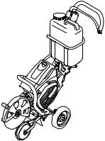
Guide trolley.............................................................................. |
23 |
Water tank (the component of trolley)....................................... |
23 |
Mains/pressure water system................................................... |
23 |
Maintenance chart......................................................................... |
24 |
Fault location................................................................................. |
24 |
Troubleshooting............................................................................ |
25 |
Storage........................................................................................... |
26 |
Packing
Your DOLMAR Power Cutter is packed in a cardboard box to prevent shipping damage.
Cardboard is a basic raw material and is consequently reuseable or suitable for recycling (waste paper recycling).
2
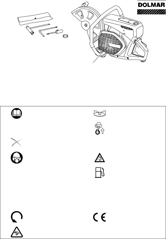
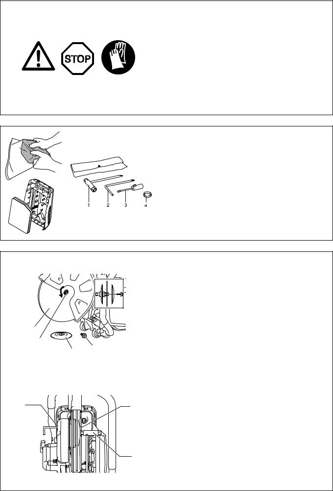
Delivery inventory
|
|
|
|
|
|
|
|
|
|
|
|
|
|
|
|
|
|
|
|
|
2 |
3 |
4 |
5 |
|||
1.Power Cutter
2.13/19 AF combination wrench
3.Star-shaped wrench
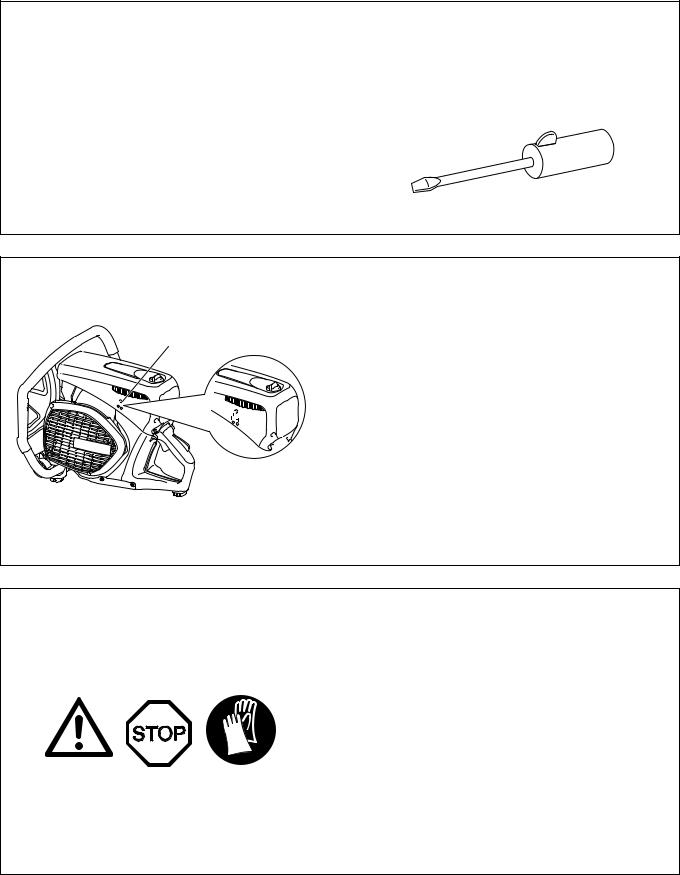
4.Carburetor adjustment screwdriver
5.Adapter ring (Tools for some countries may not require this ring.)
6.Instruction manual (not shown)
1
In case one of the parts listed should not be included in the delivery inventory, please consult your sales agent.
Symbols
You will notice the following symbols on the saw and in the Instruction Manual:
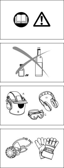
Read instruction manual and follow the warning and safety precautions!
Particular care and caution!
Forbidden!
Wear protective helmet, eye and ear protection, and respiratory protection!
Cutting disc dimensions
Engine-Manual start
Stop engine!
Warning! Kickback!
Wear protective gloves! |
Fuel (Gasoline) |
No smoking! |
First Aid |
No open fire! |
Recycling |
Direction of cutting wheel rotation |
CE - Marking |
WARNING: the max. peripheral |
|
speed of the cutting disc is 80 m/s! |
|
3
SAFETY PRECAUTIONS
General precautions
-- The operator MUST read this instruction manual to ensure safe operation
(even if you already have experience in using cutoff saws). It is important to be familiar with the operation of this particular cutoff saw. Users insufficiently informed will endanger themselves as well as others due to improper handling.
-- Let only persons who have experience in using cutoff saws work with this unit.
When letting another person use the Power Cutter, this instruction manual must be provided along with it.
-- First-time operators should ask a specialist to instruct them in working with gasoline-powered cutoff saws.
-- Children and persons under 18 years of age must not be allowed to use this Power Cutter. Persons over the age of 16 years may, however, use the Power Cutter for the purpose of being trained as long as they are under the supervision of a qualified trainer.
-- Working with the Power Cutter requires high concentration.
-- Operate the Power Cutter only if you are in good physical condition. If you are tired, your attention will be reduced. Be especially careful at the end of a working day. Perform all work calmly and carefully. The user has to accept liability for others.
-- Never work while under the influence of alcohol, drugs, medication or other substances which may impair vision, dexterity or judgement.
-- A fire extinguisher must be available in the immediate vicinity.
-- Asbestos and other materials that can release toxins may be cut only with the necessary safety precautions and after notification of the proper authorities and under their supervision or that of a person appointed by them.
Protective equipment
-- In order to avoid head, eye, hand or foot injuries as well as to protect your hearing the following protective equipment must be used during operation of the Power Cutter:
-- The kind of clothing should be appropriate, i. e. it should be tight-fitting but not be a hindrance. Clothing in which grains of material can accumulate (trousers with cuffs, jackets and trousers with wide-open pockets, etc.) must not be worn, particularly when cutting metal.
-- Do not wear any jewellery or clothing that can get caught or distract from the operation of the Power Cutter.
-- It is necessary to wear a protective helmet whenever working with the Power Cutter. The protective helmet (A) is to be checked in regular intervals for damage and is to be replaced after 5 years at the latest. Use only approved protective helmets.
-- The helmet visor (B) protects the face from dust and material grains. In order to prevent injuries to eyes and face, always wear protective goggles (C) or visor when using the Power Cutter.
-- To prevent hearing damage, always wear suitable personal hearing protection (ear muffs (D), ear plugs, etc.). Octave brand analysis upon request.
-- When dry-cutting dust-producing materials such as stone or concrete, always wear approved respiratory protection (E).
-- Work gloves (F) of tough leather are part of the required work kit of the Power Cutter and must always be worn when working with the Power Cutter.
1
2
3
E F
4
4

-- Always wear safety shoes or boots (G) with steel toes, non-skid soles, and leg protectors when working with the Power Cutter. Safety shoes equipped with a protective layer provide protection against cuts and ensure a secure footing.
-- Always wear a work suit (H) of sturdy material.
Fuels / Refuelling
-- Go to a safe, level place before refuelling. Never refuel while on scaffolding, on heaps of material, or in similar places!
-- Switch off the engine before refuelling the Power Cutter.
-- Do not smoke or work near open fires (6).
-- Let the engine cool down before refuelling.
-- Fuels can contain substances similar to solvents. Eyes and skin should not come in contact with mineral oil products. Always wear protective gloves when refuelling
(not the regular work gloves!). Frequently clean and change protective clothes.
Do not breathe in fuel vapors. Inhalation of fuel vapours can be hazardous to your health.
-- Do not spill fuel. If a spill occurs, clean off the Power Cutter immediately. Fuel should not come in contact with clothes. If your clothes have come in contact with fuel, change them at once.
-- Ensure that no fuel oozes into the soil (environmental protection). Use an appropriate base.
-- Refuelling is not allowed in closed rooms. Fuel vapors will accumulate near the floor (explosion hazard).
-- Ensure to firmly tighten the screw cap of the fuel tank.
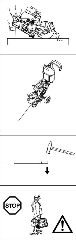
-- Before starting the engine, move to a location at least 3 meters
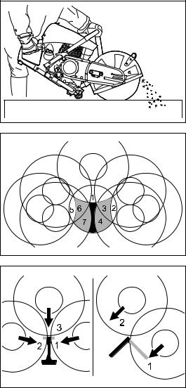
(approx. 3 1/4 yards) from where you fuelled the Power Cutter (7), but not within the extended swing range of the cutting disc (direction of sparks).
-- Fuel cannot be stored for an unlimited period of time. Buy only as much as will be consumed in the near future.
-- Use only approved and marked containers for the transport and storage of fuel. -- Keep fuel away from children!
Putting into operation
-- Do not work on your own. There must be someone around in case of an emergency (within shouting distance).
-- Observe all anti-noise regulations when working in residential areas.
-- Never use the Power Cutter near inflammable materials or explosive gases!
The Power Cutter can create sparks leading to fire or explosion!
-- Make sure that all persons within 30 meters (33 yards), such as other workers, are wearing protective gear (see “Protective equipment”) (8). Children and other unauthorized persons must remain more than 30 meters away from the working area. Keep an eye out for animals as well (9).
-- Before starting work the Power Cutter must be checked for perfect function and operating safety according to the prescriptions.
In particular, make sure that the cutting wheel is in good condition (replace immediately if torn, damaged or bent), the cutting wheel is properly mounted, the protection hood is locked in place, the hand guard is properly mounted, the V-belt has the proper tension, the throttle moves easily and the grips are clean and dry, and the combination switch functions properly.
-- Start the Power Cutter only after complete assembly and inspection. Never use the Power Cutter when it is not completely assembled.
5
6 |
3 meters |
7 |
30 m
= wearing Protective Equipment
8
9
5
Cutoff discs
-- The protection hood must always be on! Change discs only with the engine off!
-- There are two basic types of cutoff discs: -- For metal (hot cutting)
-- For masonry (cold cutting)
NOTE:
When using diamond cutoff discs, always make sure to observe the “direction of rotation” markings. Diamond discs should only be used for cutting masonry/brick/ concrete etc.
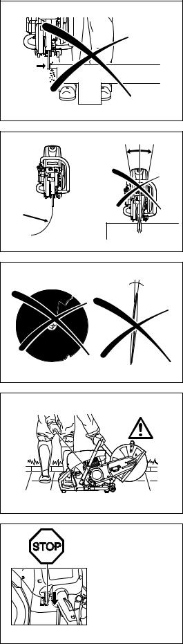
-- Cutoff discs are intended only for radial loading, i.e. for cutting.
Do not grind with the sides of the cutting disc! This will break the disc (10)!
 CAUTION:
Never change direction (turning radius less than 5 meters / 5 1/2 yards), exert lateral (sideways) pressure, or tip the Power Cutter during cutting (11)!
-- Use a cutting disc only for cutting the materials it is intended for. The proper type of disc must be used, for either metals or masonry.
-- The arbour hole (bore) of the cutting disc must fit the shaft exactly. If the arbour hole is larger than the shaft diameter, a spacer ring must be used (accessories).
-- Use only cutting wheels approved by the DSA (German Abrasive Disc
Committee) or equivalent organisation for freehand cutting at up to 4,370 RPM
(= 80 m/sec. at circumference) for 14”/355 mm discs, or up to 5,100 RPM
(= 80 m/sec. at circumference) for 12”/300 mm discs.
-- The disc must be free of defects (12). Do not use defective cutting discs.
Always tighten the cutting disc mounting bolt to a torque of 30 Nm. Otherwise, the cutting disc can twist.
-- Before starting the cutting disc, make sure you have a steady footing.
-- Put the Power Cutter into operation only as described in this instruction manual (13). Always place your left foot in the rear handle and grasp the other handle firmly (with thumb and fingers). Other starting methods are not allowed.
-- When starting the Power Cutter it must be well supported and securely held. The cutting disc must not be touching anything.
-- If the cutting disc is new, test it by running it at least 60 seconds at top speed. When doing this, make sure that no persons or body parts are in the extended swing range of the disc, in case it is defective and flies apart.
-- When working with the Power Cutter always hold it with both hands. Take the back handle with the right hand and the tubular handle with the left hand.
Hold the handles tightly with your thumbs facing your fingers.
-- CAUTION: When you release the throttle lever the disc will keep spinning for a short period of time (free-wheeling effect).
-- Continuously ensure that you have a safe footing.
-- Hold the Power Cutter such that you will not breathe in the exhaust gas. Do not work in closed rooms or in deep holes or ditches (danger of poisoning by fumes).
-- Switch off the Power Cutter immediately if you observe any changes in its operating behavior.
-- Switch off the engine before inspecting the V-belt tension or tightening it, replacing the cutting wheel, repositioning the cutter attachment (side or middle position) or eliminating faults (14).
-- Turn off the engine immediately and check the disc if you hear or feel any change in cutting behaviour.
-- Turn off the Power Cutter when taking a break or stopping work (14). Place the unit in such a way that the disc is not touching anything and cannot endanger anyone.
-- Do not put the overheated Power Cutter in dry grass or on any inflammable objects. The muffler is very hot (danger of fire).
-- IMPORTANT: After wet cutting, first turn off the water feed and then let the disc run at least 30 seconds, to fling off the remaining water and prevent corrosion.
10
min. 5 m
11
12
13
• Maintenance
• Refuelling
• Changing cutoff discs
• Repositioning the cutting attachment
• Stopping work
• Transport
• Putting out of function
14
6
Kickback and lock-in
-- When working with the Power Cutter there is a danger of kickback and lock-in.
-- Kickback occurs when the top of the cutting disc is used for cutting (15).
-- This causes the Power Cutter to be thrown back toward the user with great force and out of control. Risk of injury!
To prevent kickback, observe the following:
-- Never cut with the section of the cutting disc shown in figure 15.
Be especially careful when reinserting the disc into cuts that have already been started!
-- Lock-in occurs when the cut narrows (crack, or workpiece under stress).
-- This causes the Power Cutter to suddenly jump forward, out of control and with great force. Risk of injury!
To prevent lock-in, observe the following:
-- When reinserting the disc into previous cuts, have the Power Cutter running at top speed. Always cut at top speed.
-- Always support the workpiece so that the cut is under tension (16), so that the cut does not press together and jam the cutting disc as it proceeds through the material.
-- When starting a cut, apply the disc to the workpiece with care.
Do not just shove it into the material.
-- Never cut more than one piece at a time! When cutting, make sure that no other workpiece comes into contact.
Working behavior / Method of working
-- Before starting work, check the work area for any hazards (electrical wires, inflammable substances). Clearly mark the work area (for example with warning signs or by cordoning off the area).
-- When working with the Power Cutter hold it firmly by the front and rear handles.
Never leave the Power Cutter unattended!
-- Whenever possible run the Power Cutter at the rated arbour speed (see
“Technical data”).
-- Only use the Power Cutter during good light and visibility periods.
Be aware of slippery or wet areas, and of ice and snow (risk of slipping).
-- Never work on unstable surfaces. Make sure that there are no obstacles in the working area, risk of stumbling. Always ensure that you have a safe footing.
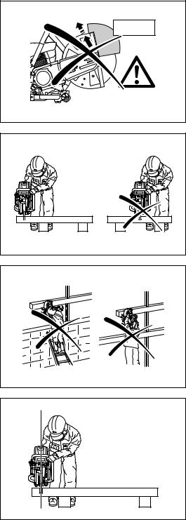
-- Never cut above your shoulder height (17). -- Never stand on a ladder to cut (17).
-- Never use the Power Cutter while standing on scaffolding.
-- Do not lean over too far when working. When putting down and picking up the Power Cutter, do not bend over from the waist, but instead bend in the knees. Save your back!
-- Guide the Power Cutter in such a way that no part of your body is within the extended swing range of the disc (18).
-- Use cutting discs only for the materials for which they are designed!
-- Do not use the Power Cutter to lift up and shovel away pieces of material and other objects.
Important! Before cutting, remove all foreign objects, such as rocks, gravel, nails etc. from the cutting area. Otherwise, such objects can be flung away by the disc with great speed. Injury hazard!
-- When cutting workpieces down to length use a firm support. If necessary, secure the workpiece from slipping, but do not steady it with your foot or allow another person to hold it.
-- When cutting round items, always secure them against rotation.
-- When guiding the Power Cutter by hand, use the side mounting position of the cutter attachment only when actually necessary.
Otherwise, always use the central position. This gives the unit a better balance, for reduced operator fatigue.
15 |
16 |
17
18
7
Cutting metals
 IMPORTANT!
Always wear approved respiratory protection!
Materials that can release toxic substances may be cut only after notifying the proper authorities and under their supervision or that of a person appointed by them.
 CAUTION:
The rapid rotation of the cutting disc heats metal and melts it at the point of contact. Swing the guard as far down as possible behind the cut (19) in order to direct the stream of sparks forward, away from the operator (fire hazard).
-- Determine the direction of cutting, mark the cut and apply the disc to the material at moderate speed, to cut a guide groove before going to top speed and applying more pressure to the Power Cutter.
-- Keep the disc straight and vertical. Do not tip it, as this can break it.
-- The best way to get a good, clean cut is to pull or move the Power Cutter back and forth. Do not simply press the disc into the material.
-- Thick round stock is best cut in stages (20).
-- Thin tubing and pipes can be cut with a simple downward cut.
-- Cut large-diameter pipes as for round stock. To prevent tipping and for better control, do not let the disc sink too deeply into the material. Instead, always cut shallow around the whole piece.
-- Worn discs have a smaller diameter than new discs, so that at the same engine speed they have a lower effective circumferential speed and therefore do not cut as well.
-- Cut I-beams and L-bars in steps; see Figure 21.
-- Cut bands and plates like pipes: along the wide side with a long cut.
-- When cutting material under stress (supported material or material in structures), always make a notch in the thrust (pressure) side, and then cut from the tension side, so that the disc does not lock in. Secure cutoff material from falling!
 CAUTION:
If there is a chance that the material is under stress, be prepared for it to kick back. Make sure you can get out of the way if you have to!
Be particularly careful in scrap-metal yards, junkyards, at accident sites, and with haphazard piles of material. Precariously balanced pieces or pieces under stress can act in unpredictable ways, and may slide, jump out, or burst. Secure cutoff material from falling! Always exercise extreme caution and use only equipment that is in perfect working order.
Observe the accident-prevention rules and regulations of your employer and/ or insurance organization.
Cutting masonry and concrete
IMPORTANT!
Always wear approved respiratory protection!
Asbestos and other materials that can release toxic substances may be cut only after notifying the proper authorities and under their supervision or that of a person appointed by them. When cutting prestressed and reinforced concrete piles, follow the instructions and standards of the responsible authorities or the builder of the structural member. Reinforcement rods must be cut in the prescribed sequence and in accordance with applicable safety regulations.
NOTE:
Mortar, stone, and concrete develop large quantities of dust during cutting. To increase the lifetime of the cutting disc (by cooling), to improve visibility, and to avoid excessive dust creation, we strongly recommend wet cutting instead of dry cutting.
19
20
21
8
In wet cutting, the disc is wetted at an equal rate on both sides by a trickle of water. DOLMAR offers the right accessories for all wet cutting applications (see also
“SPECIALACCESSORIES”).
-- Remove foreign objects such as sand, stones and nails found within the working area. CAUTION: Watch out for electric wires and cables!
The rapid rotation of the cutting disc at the point of contact throws fragments out of the cut groove at high speed. For your safety, swing the protection hood down as far as possible behind the cut (23), so that material fragments are thrown forward, away from the operator.
-- Mark the cut, and then make a groove about 5 mm (just under 1/5”) along the entire length of the planned cut. This groove will then guide the Power Cutter accurately guring the actual cutoff.
NOTE:
For long, straight cuts we recommend using a trolley (24, see also “SPECIAL
ACCESSORIES”). This makes it much easier to guide the unit straight.
-- Perform the cut with a steady back-and-forth motion.
-- When cutting slabs to size, you need not cut through the entire material thickness (creating unnecessary dust). Instead, simply make a shallow groove, and then knock off the excess material cleanly on a flat surface (25).
CAREFUL!
When cutting into lengths, cutting through material, making cutouts, etc., always
make sure to plan the direction and sequence of cuts in such a way that the disc does not get jammed by the cut-off piece, and that no persons can be injured by falling pieces.
Transport and storage
-- Always turn off the Power Cutter when transporting it or moving it from place to place on a site (26).
-- Never carry or move the unit with the engine on or the disc moving!
-- Carry the unit only by the tubular (middle) handle with the cutting disc pointing behind you (26). Avoid touching the exhaust muffler (burn hazard!)
-- When moving the Power Cutter over longer distances, use a wheelbarrow or wagon.
-- When transporting the Power Cutter in a vehicle, make sure it is securely positioned in such a way that no fuel can leak out.
Always remove the cutting disc before transporting the unit in a vehicle.
-- The Power Cutter should be stored safely in a dry place. It must not be left outdoors! Always dismount the cutting disc before storage. Keep the Power Cutter away from children.
-- Before long-term storage and before shipping the Power Cutter, follow the instructions in the chapter on “Storage”. ALWAYS empty the fuel tank and run the carburetor dry.
-- When putting cutting discs in storage, be careful to: -- Clean and dry them well.
-- Store them lying down flat.
-- Avoid dampness, freezing temperatures, direct sunshine, high temperatures and temperature fluctuations, as these can cause breakage and splintering.
-- Always check new cutting discs or cutting discs that have been in storage to make sure that they are free of defects.
23 |
24 |
25 |
26
9
Maintenance
-- Before performing maintenance work switch off the Power Cutter (27) and pull out the plug cap.
-- Always check the Power Cutter before using it to make sure that it is in good working order. In particular, make sure that the cutting disc is properly mounted. Make sure that the cutting wheel is undamaged and suitable for the job it will be used for.
-- Operate the Power Cutter only at a low noise and emission level.
For this ensure the carburetor is adjusted correctly.
-- Clean the Power Cutter regularly.
-- Check the fuel tank cap regularly for good sealing.
Observe the accident prevention instructions issued by trade associations and insurance companies. NEVER make any modifications to the Power Cutter! You will only be putting your own safety at risk!
Perform only the maintenance and repair works described in the instruction manual. All other work must be carried out by DOLMAR Service (28).
Use only original DOLMAR spares and accessories.
The use of non-DOLMAR spares, accessories, or cutting discs increases the risk of accident. We cannot accept any responsibility for accidents or damage occurring in association with the use of cutting discs or accessories other than original DOLMAR.
27
SERVICE
28
First aid (29)
Make sure that a first aid kit is always immediately available close by. Immediately replace any items used from the first aid box.
When calling for help, give the following information:
-- Place of the accident -- What happened
-- Number of injured people -- Kind of injuries
-- Your name!
NOTE:
Individuals with poor circulation who are exposed to excessive vibration may 29 experience injury to blood vessels or the nervous system.
Vibration may cause the following symptoms to occur in the fingers, hands or wrists:
“Falling asleep” (numbness), tingling, pain, stabbing sensation, alteration of skin colour or of the skin.
If any of these symptoms occur, see a physician!
10
Technical data
Item |
|
Model |
|
PC-7612V |
|
PC-7614V |
|
||
|
|
|
|
|
|||||
|
|
|
|
|
|
|
|
|
|
|
|
|
|
|
|
|
|
|
|
Engine |
Displacement |
cm3 |
|
|
|
75.6 |
|
|
|
|
Bore |
mm |
|
|
|
51 |
|
|
|
|
Stroke |
mm |
|
|
|
37 |
|
|
|
|
Max. power |
kW |
|
|
|
3.0 |
|
|
|
|
|
|
|
|
|
|
|
|
|
|
Max. torque |
Nm |
|
|
|
4.6 |
|
|
|
|
|
|
|
|
|
|
|
|
|
|
Idling speed |
min-1 |
|
|
|
3,000 |
|
|
|
|
Clutch |
|
|
|
Auto centrifugal system |
|
|||
|
Clutch engagement speed |
min-1 |
|
|
|
4,200 |
|
|
|
|
Engine speed limitation |
min-1 |
|
|
|
9,100 |
|
|
|
|
Max. spindle speed |
min-1 |
|
|
|
4,300 |
|
|
|
|
Carburetor |
|
|
|
Diaphragm type |
|
|||
|
Ignition system (with speed limitation) |
|
|
|
Non-contact, magnet type |
|
|||
|
|
|
|
|
|
|
|
||
|
Spark plug |
Type |
|
|
NGK CMR6H |
|
|||
|
|
|
|
|
|
|
|
|
|
|
Electrode gap |
mm |
|
|
|
0.5 |
|
|
|
|
|
|
|
|
|
|
|
||
|
Starting system |
|
|
|
Recoil system |
|
|||
|
Fuel consumption at max. load per |
kg/h |
|
|
|
1.2 |
|
|
|
|
ISO 8893 |
|
|
|
|
|
|
|
|
|
Specific consumption at max. load per |
g/kWh |
|
|
|
400 |
|
|
|
|
ISO 8893 |
|
|
|
|
|
|
|
|
|
Fuel |
|
|
|
Automobile gasoline (petrol) |
|
|||
|
|
|
|
|
|
|
|
|
|
|
Fuel tank capacity |
l |
|
|
|
1.1 |
|
|
|
|
Lubricant (engine oil) |
|
API grade SF class or higher SAE 10W-30 oil (automobile 4-stroke engine oil) |
||||||
|
Lubricant quantity |
l |
|
|
|
0.22 |
|
|
|
|
|
|
|
|
|
|
|
|
|
Cutting disc for 80 m/sec. or higher 1) (DSA approved): |
mm |
|
300/20.0/5 2) |
|
350/25.4/5 2) |
|
|||
dimensions |
|
|
|
|
|
|
|
|
|
Sound pressure level (LpA) per EN ISO 19432 3) |
dB (A) |
|
|
|
92.7 |
|
|
||
|
Uncertainty (K) |
dB (A) |
|
|
|
2.5 |
|
|
|
Sound power level (LWA) per EN ISO 19432 |
dB (A) |
|
|
|
104.6 |
|
|
||
|
Uncertainty (K) |
dB (A) |
|
|
|
2.5 |
|
|
|
|
|
|
|
|
|
|
|
|
|
Vibration acceleration ah, w per EN ISO 19432 |
|
|
|
|
|
|
|
|
|
- Front handle (idle/rated spindle speed) |
m/s2 |
|
|
|
2.7 |
|
|
||
|
Uncertainty (K) |
m/s2 |
|
|
|
2.0 |
|
|
|
- Rear handle (idle/rated spindle speed) |
m/s2 |
|
|
|
1.8 |
|
|
||
|
Uncertainty (K) |
m/s2 |
|
|
|
2.0 |
|
|
|
Arbor diameter |
|
mm |
20.0 |
|
25.4 |
|
20.0 |
|
25.4 |
Spindle diameter |
mm |
|
|
|
17 |
|
|
||
Minimum flange outside diameter |
mm |
|
|
|
102 |
|
|
||
Max. cutting depth |
mm |
|
100 |
|
116 |
|
|||
|
|
|
|
|
|||||
Power Cutter Dimensions (overall length x overall |
|
761 mm x 310 mm x 435 mm |
|
780 mm x 310 mm x 455 mm |
|||||
width x overall height) |
|
|
|
|
|
|
|
|
|
V-belt no. |
|
no. |
|
|
|
225094-6 |
|
|
|
Overall weight (tanks empty, without cutting disc) |
kg |
|
12.7 |
|
12.9 |
|
|||
1)Circumference speed at max. engine speed
2)Outside diameter / arbor hole / thickness
3)At the workplace (at user’s ear)
11
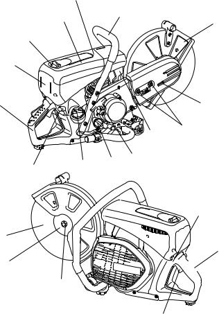
Denomination of components |
|
5 |
|
|
|
|
1. |
Rear handle |
4 |
|
|
6 |
7 |
2. |
Filter cover |
|
|
|
||
3. |
Lock screw |
|
|
|
|
|
4. |
Top cover for air filter and spark plug cap |
3 |
|
|
|
|
5. |
Top cover |
|
|
|
|
|
6. |
Front handle |
2 |
|
|
|
|
7. |
Protection hood |
|
|
|
|
|
8. |
Tensioning screw |
|
|
|
|
|
9. |
Hex. nut |
|
|
|
|
|
10. |
Muffler |
1 |
|
|
|
|
11. |
Starter grip |
|
|
|
8 |
|
12. |
Oil tank cap |
|
|
|
|
|
13. |
Fuel tank cap |
|
|
|
|
|
14. |
Fuel pump (Primmer) |
|
|
|
|
9 |
15. |
Cutting disc |
|
|
|
|
10 |
16. |
Outer flange |
|
|
|
|
|
17. |
Hex bolt |
|
|
|
|
11 |
18. |
Switch |
|
13 |
12 |
|
|
19. |
Safety locking button |
14 |
|
|
||
|
|
|
||||
20. |
Throttle lever |
|
|
|
|
|
|
|
|
|
|
||
|
|
|
|
|
|
18 |
15


 19 16
19 16 


17
20
12
PUTTING INTO OPERATION
 CAUTION:
Always turn off the engine and pull off the spark plug cap before doing any work on the Power Cutter! Always wear protective gloves!
 CAUTION:
Start the Power Cutter only after complete assembly and inspection.
For the following work, use the assembly tools included with delivery:
1.13/16 AF combination wrench
2.Star-sharped wrench
3.Carburetor adjustment screwdriver
4.Adapter ring
Place the Power Cutter on a stable surface and carry out the following assembly steps:
 No air filter is installed!
Before operation, squeeze the supplied filter several times so that oil is evenly immersed in the entire filter. Insert an oiled foam filter (pre-filter), as shown in the adjacent illustration! To do this, take off the filter cover (see the chapter on Cleaning/ changing the air filter).
Schematic drawing
4
5
6 7
8 |
6 |
2
1
Mounting the cutting disc
WARNING:
•When installing a diamond cutting disc, be sure to mount it so that the arrow is in the same direction as the outer flange (6) rotates. Mounting the diamond cutting disc (4) with its arrow direction opposite to that on the wheel cover may cause chipping of the disc edge and personal injury.
•When installing a cutting disc (4), always use the ring that matches the bore of the cutting disc and the diameter of the spindle (5). Failure to use rings that mate may cause tool vibration resulting in serious personal injury.
•Only use cutting discs with the bore that matches the diameter of the ring(s) provided. Using discs that do not mate may cause tool vibration resulting in serious personal injury.
•Inspect a cutting disc for damage. (see the section titled
“Cutoff discs” in SAFETY PRECAUTIONS.)
1.Insert the star-shaped wrench (2) into the hole (8) to prevent the spindle (5) from rotating.
NOTE: When the holder of the pressure water system is installed in the hole in the tool, remove it before mounting the cutting disc.
2.While holding on the wrench (2) in that position, use the combination wrench (1) provided and turn the bolt (7) securing the disc counterclockwise and remove the bolt (7) and outer flange (6).
3.Mount a diamond cutting disc/cut-off abrasive disc (4) on the arbor (5). And then put the outer flange (6) on the spindle so that the two parallel flat surface on the outer flange fit the
spindle flat surface and firmly tighten the bolt clockwise.
To install a cutting disc, mount a ring with the same matching diameter as the disc bore and the O ring provided to retain the ring on the spindle before installing a diamond cutting disc. And then install the cutting disc.
NOTE: Tighten the hex bolt firmly (25 - 31 Nm), as otherwise the cutting wheel may slip during cutting.
13
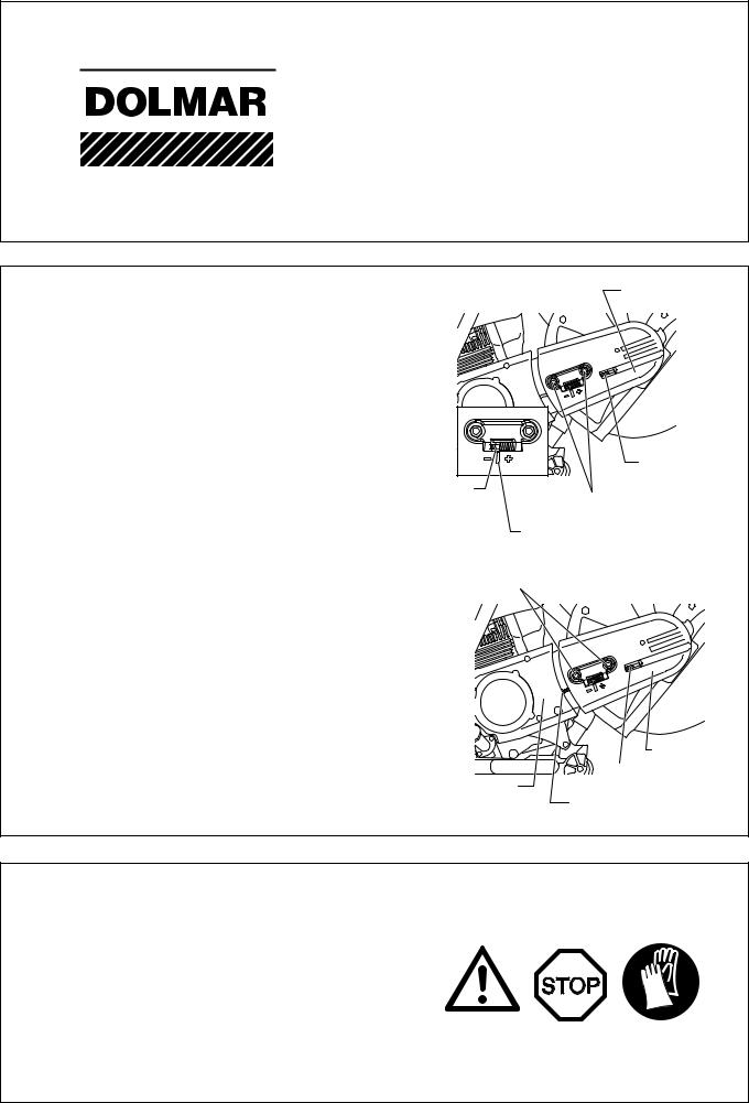
Tightening the V-belt / Checking V-belt tension
IMPORTANT:
Exact V-belt tension is essential for maximum cutting performance with minimum fuel consumption. Improper V-belt tension will result in premature wear to the V-belt and V-belt wheel or damage to the clutch bearing.
NOTE: The two hex. nut (9) must be loosened before tightening the V-belt or checking the tension.
To increase the belt tension, turn the tension screw (10) to the right (clockwise) with the combination wrench included with the
Power Cutter.
The belt tension is correctly adjusted when the nut (11) is located as shown in the figure compared to the position of the mark (12).
IMPORTANT:
•After tightening/inspection, make certain to tighten the hex. nut (9) (25 - 31 Nm).
•Do not adjust the belt tension while the machine is hot. There is a risk of burn injury.
11
10 9
12
Before operating
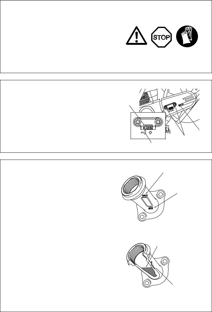
1. Checking/replenishing engine oil
•With the engine in a cool state, check/replenish engine oil in the following way.
•Position engine on a flat level, and check to see whether oil is within the range of MAX and MIN of the oil tank.
•If oil is insufficient (near the MIN mark of the oil tank), fill the oil tank with oil to the MAX mark.
•Oil quantity can be checked externally without removing the oil cap as the oil level can be seen at the external, see-through, measuring mark window.
•For reference, oil needs to be replenished every ten operating hours (one tank of oil for ten fuel refuels).
•Replace extremely dirty or discolored oil.
<Recommended oil>..... |
Use API grade SF class or higher SAE |
|
10W-30 oil (automobile 4-stroke engine |
|
oil). |
<Oil quantity>................ |
0.22 L (220 mL) |
NOTE:
•If the engine is not stored in the upright position, oil will circulate through the engine, which will mean that there will be excessive oil in the Power Cutter when replenishing.
•If oil exceeds the MAX mark, it may leak out causing dirtying or white smoke.
Oil replacement Point 1 <Oil cap>
Interval of replacement: Initially, after 20 operating hours, and subsequently every 30 operating hours.
•Clean away the dirt from around oil filling neck and then remove oil cap.
•Place the oil cap on a surface where it will not pick up grit and dirt. If the cap is put back on in a dirty state, oil circulation may deteriorate and engine parts become worn, which may cause mechanical failure.
MAX mark
MIN mark
Oil
The oil is visible from here, so the MAX and MIN marks can be used to check the quantity of oil.
14
Oil tank cap
Fuel tank cap
Level

 Fuel MAX
Fuel tank
(1)Place engine on the level and remove oil cap.
(2)Replenish oil to the base of the oil filling neck.
When replenishing oil, use a proper lubricant container for refilling.
(3)Firmly tighten oil cap. If oil cap is loose, oil may leak out.
Oil replacement Point 2 <What to do if oil is spilled>
If oil is spilt between fuel tank and engine, and the Power Cutter operated, oil will be sucked in via the cold air intake, which may cause dirtying. Always wipe off spilt oil before using the power cutter.
2. Refueling
WARNING:
•Always observe the following items when refueling. Failure to do so may cause flames or fire.
•Refuel away from flames. In addition, never smoke or bring any form of flame near to fuel or power cutter during refueling.
•Stop the engine and let it cool down before refueling.
•Always open fuel tank cap slowly to release internal pressure in a controlled manner. Failure to do so may cause fuel to spray out because of internal pressure.
•Be careful not to spill fuel. If fuel is spilt, fully wipe away fuel.
•Refuel in a well-ventilated location.
•Always handle fuel with full care.
•If fuel comes into contact with skin and/or eyes, it may cause an allergic reaction and/or inflammation.
In cases of such allergic reactions and/or inflammation, etc., seek medical advice from a specialist doctor immediately.
<Fuel storage period>
As a rule, fuel held in a proper fuel container, in a shaded location, with good ventilation, should be used up within four weeks. If a proper fuel container is not used and/or the cap is left off, etc., and the season is summer, fuel may deteriorate in one day.
Storing the Power Cutter and fuel container
•Store Power Cutter and fuel container away from direct sunlight in a cool location.
•Do not leave fuelled up Power Cutter or fuel container in automobile or automobile trunk (boot).
<Fuel>
The engine is a four-stroke engine, so use automobile gasoline (regular gasoline/petrol) to run the engine.
Fuel points
•Do not use a gasoline mixture (engine oil mixed with gasoline). Doing so may cause carbon build up and mechanical failure.
•The use of old fuel may cause poor engine startup.
<Refueling>
Always stop the engine and let it cool down before refueling.
<Usable Gasoline> ..... Automobile gasoline (petrol)
•Slightly loosen the fuel tank cap to release pressure and thus equalize external and internal air pressure.
•Remove fuel tank cap and refuel. (Do not fill to the top of the tank neck.)
•After refueling, firmly tighten on fuel tank cap.
•The fuel tank cap is a consumable product. Therefore, if it shows wear or other abnormalities, replace it. (Rough guide to replacement is once every two or three years.)
15
Operating
Starting
 WARNING:
Do not start the engine in locations where refueling has taken place. Move at least three meters away from the place where the Power Cutter was fuelled.
• Failure to do so may cause flames or fire.
 CAUTION:
Before starting engine, be sure to check that the cutting disc is not touching the ground or any other obstacle.
• If the cutting disc is touching the ground or other obstacle, it may cause an accident.
As soon as the engine starts, the cutting disc will rotate, so be fully aware of nearby people and obstacles.
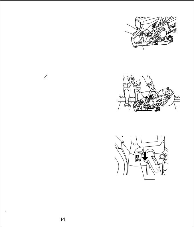
1. Cold-starting
(1)Repeatedly press primer pump until fuel enters it.
(2)Flip switch in direction of  (choke).
(3)Hold down rear handle with a foot and firmly hold down tubular handle with a hand.
(4)Vigorously pull the start handle repeatedly until the first firing up sound is heard.
Warming up
•Once engine starts, hold down safety lever, and squeeze and release throttle repeatedly for one or two minutes to warm up the engine.
•Once engine speed stabilizes and it revs smoothly from low to high speed, warming up is complete.
2. Starting up when engine is warm
Press the primer pump several times. From the outset, place the switch in the [I] (operating) position, and start the engine using task (3) of procedure 1 above.
NOTE:
•Repeatedly pulling and releasing the starter grip with the switch set to choke will flood the engine with fuel, making start up difficult.
•When the engine stops, never squeeze the throttle lever. Unnecessarily squeezing the throttle lever with the engine stopping will flood the engine with fuel, making start up difficult.
•If the engine does become flooded with fuel, remove the spark plug, and slowly pull the starter handle several times to remove the excess fuel. Also, dry the electrode section of the spark plug.
•Do not pull starter handle to the limit of the rope, as doing so shortens the lifespan of the rope. Furthermore, gently return the starter handle without suddenly letting go of it.
•Avoid letting the Power Cutter run at maximum idling speed, as doing so will shorten the lifespan of the engine.
3. Stopping
To stop the engine, release the throttle, and set the switch to the
 (Stop) position.
If the choke lever is wrongly moved to the  position to stop the tool, use half throttle to restart.
Starter grip
Switch
Safety locking button
Throttle lever
Switch
16
Adjusting the carburetor
NOTE: This engine is equipped with an electronic ignition to limit the speed. The carburetor also has a fixed jet which cannot be adjusted.
At the factory the idling speed has been set to
approx. 3,000 1/min., but the running-in process of a new engine may require slight readjustment of the idling speed.
Set the idling speed with a screwdriver (width of blade: 4 mm).
A screwdriver with a molded-on lug, supplied as an optional accessory, is useful for the adjustment.
|
4. Idling adjustment |
Adjusting screw |
CAUTION: Carburetor adjustment may only be done by a |
specialist DOLMAR service center! |
|
|
Do not undertake any adjustments to adjusting screws (H) |
|
and (L) without a tachometer! Incorrect adjustment can lead |
|
to engine damage! |
|
A tachometer is needed for adjustments to adjusting screws |
|
(H) and (L), because if the engine runs over its maximum |
|
rated speed, it can overheat and run out of lubricant. This |
|
can damage the engine! |
|
Only adjusting screw (T) can be manipulated by the user. If |
|
the cutting disc moves in idle (i.e. without the throttle being |
|
pressed), it is imperative to correct the idle speed! |
|
Idle speed adjustment must only be undertaken when the |
|
engine is warm, with a clean air filter. |
|
Use a screwdriver (4 mm blade) for idle adjustments. |
MAINTENANCE
 CAUTION:
• Before doing any work on the Power Cutter stop the engine and let it cool down, remove the cutting disc, pull the plug cap off the spark plug and wear protective gloves!
Carrying out maintenance directly after stopping the engine or with the plug cap on the spark plug may cause burns from hot engine or injury from inadvertent start up.
• Start the Power Cutter only after complete assembly and inspection.
• Never use gasoline, benzine, thinner, alcohol or the like. Discoloration, deformation or cracks may result.
NOTE:
• Wipe off dirt from the Power Cutter and then select a clean workplace to carry out maintenance.
17
SERVICE
IMPORTANT:
Because many of the parts and assemblies not mentioned in this Instruction Manual are vital to the safety of the unit, and because all parts are subject to a certain amount of wear and tear, it is important for your own safety that you have the unit checked and maintained regularly by a DOLMAR service center.
IMPORTANT:
If the cutting wheel breaks during cutting, the Power Cutter must be repaired by a DOLMAR service centre before being used again!
V-belt
1. Adjusting V-belt tension
•If the cutting disc halts in mid operation easily, the V-belt has slackened. If this is the case, adjust tension using the
following procedure.
(1)Loosen belt cover tightening nuts.
(2)Turn the tension adjustment screw to the right (clockwise) until the indicator nut reaches the marked position in order to increase the tension of the V-belt.
(3)Once V-belt tensioning is complete, firmly retighten the belt cover tightening nuts.
•If the cutting disc stops easily even though the tension of the V-belt has been adjusted, or the V-belt breaks, replace with a new V-belt.
2. Changing the V-belt
(1)Loosen tightening nut, and turn tension adjustment screw to the left until the end of the screw is visible.
(2)Remove tightening nuts, and then remove belt cover.
(3)Next, remove the three mounting screws, and remove the clutch cover.
(4)Remove the old V-belt, and fit on a new V-belt. Now, remount the clutch cover followed by belt cover.
(5)Adjust tension as shown in the Adjusting V-belt tension section.
Belt cover
Tensioning screw
Indication nut
Hex. nut
Mark
Hex. nut
Belt cover
Tensioning screw
Clutch cover
End of screw
Cleaning the protection hood
Over time, the inside of the protection hood can become caked with material residue (especially from wet cutting), which if allowed to accumulate can hinder the free rotation of the cutting disc. For this reason the hood must be cleaned out from time to time.
Take off the cutting wheel and remove the accumulated material from inside the hood with a strip of wood or similar implement.
Clean the shaft and all disassembled parts with a cloth.
NOTE: To install the cutting wheel see “Mounting the cutting disc”.
18
Top cover
Cover lock
Loosen
Prefilter |
Top cover |
Filter cover |
|
|
Star-shaped |
Star-shaped |
screws |
screws |
|
Inner filter
Air filter
Dust bag filter
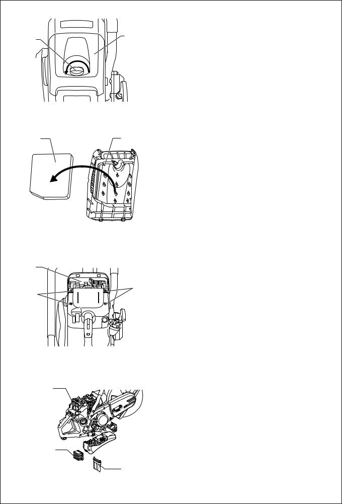
Cleaning/changing the air filter
•If the air filter becomes clogged, it may cause poor engine performance. Therefore, every time after using the Power
Cutter, be sure to clean the air filter in the following way.
•Turn the cover lock to the left and remove it.
•Remove the top cover after blowing off dust from it.
•Next, remove the prefilter.
•Remove the four star-shaped screws.
•Remove the filter cover.
•Remove the air filter.
•Remove the dust bag filter from the filter cover and gently tap and blow on it to clean.
•Gently tap and blow on the inner filter to remove dirt and dust.
Also, periodically wash the inner filter in soapy water and dry thoroughly.
•To clean the air filter tap it gently. If an air compressor is to be used, blow the compressed air onto the inside of the air filter.
Do not wash the air filter.
•Blow off dust from around the filters.
•Reassemble the air filter to filter cover once cleaning is finished.
•Tighten the cover lock firmly.
19
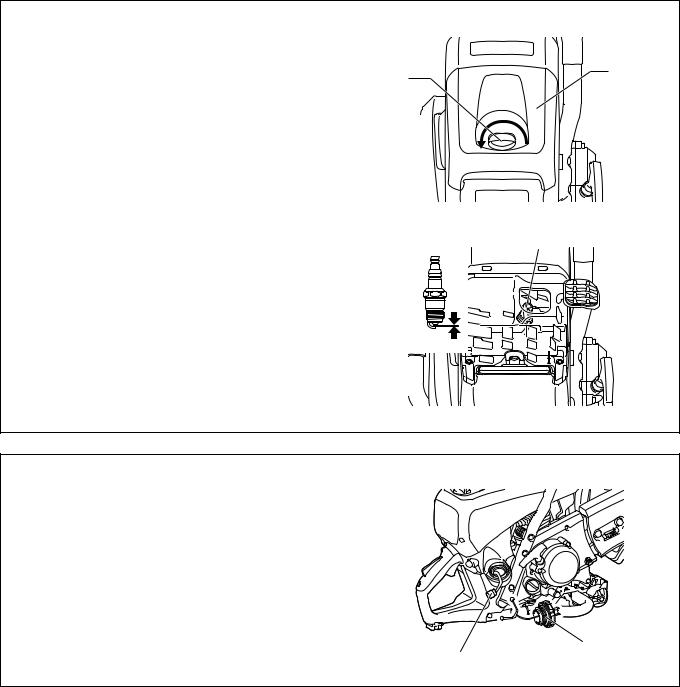
Spark plug maintenance
(1) |
Loosen the cover lock and remove the top cover. |
|
|
|
(2) |
Open plug cover, remove plug cap, and remove spark plug. |
|
Top cover |
|
(3) |
Check to see whether or not the electrode gap is 0.5 mm. If |
Cover lock |
||
|
||||
|
the gap is too big or too small, adjust it to 0.5 mm. |
|
Loosen |
|
(4) |
If carbon and/or dirt has gathered on spark plug, clean, |
|
||
|
and then remount. An excessively worn or burnt spark plug |
|
|
|
|
should be replaced with a new one. |
|
|
|
(5) |
After carrying out maintenance on the spark plug, remount it, |
|
|
|
|
attach plug cap, and then secure plug cover. |
|
|
Plug cap
0.5 mm
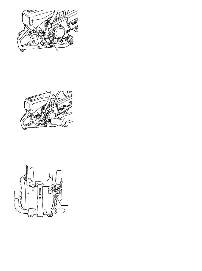
Replacing the suction head
The fuel tank filter (13) of the suction head can become clogged. It is recommended to replace the suction head once every three months in order to ensure unimpeded fuel flow to the carburetor.
Unscrew the fuel tank cap (12) and pull the loss-prevention stopper out.
Empty fuel tank.
To remove the suction head for replacement, pull it out through the tank filler neck using a piece of wire bent at one end to form a hook.
 CAUTION: Do not allow fuel to come into contact with skin!
13 |
12 |
|
20
Cleaning the starter |
14 |
When the starter doesn’t work well, for example the starter rope doesn’t return to initial position, it is necessary to blow off dust from the starter (14) and the clutch (15).
To clean the starter and the clutch, remove three screws (16) for access.
15
16
21

Mounting direction
A B
Fig. 1
Tension adjustment screw
Hex. nuts
End of screw Belt cover
Hood
Fig. 2
V-belt
Fig. 3
Changing the cutting attachment position (central/side)
Mounting direction of hood
•The Power Cutter’s cutting attachment is mounted in the direction shown in Fig. A. If desired, use the following procedure to mount it in the direction shown in Fig. B.
Mounting in direction B
(1)Loosen tightening nut, and turn tension adjustment screw to the left until the end of the screw is visible. (Fig. 1)
(2)Remove tightening nuts and remove belt cover. (Fig. 1)
(3)Rotate the hood to the broken line position. Remove V-belt and then remove cutting attachment from the Power Cutter. Reposition the grip. (Fig. 2)
(4)Pick up the lock shaft with a slotted screwdriver or a plier.
(Fig. 3)
(5)Rotate the arm until it contacts the grip and return the lock shaft to the original position by hand. (Fig. 4)
Reposition the grip. (Fig. 5)
(6)Turn over the removed cutting attachment, pass bolt through hole, and remount in direction B.
Remount the V-belt to the pulley. (Fig. 6)
(7)Mount belt cover. (Fig. 7)
Turn the tension adjustment screw to adjust the tension of the
V-belt. Once tension adjustment is finished, firmly tighten the tightening nut.
Plier
Lock shaft
Fig. 4
Arm
Grip
V-belt
Relocate |
Holes |
|
|
|
|
|
|
Bolts |
|
Belt cover |
|
|
|
|
|
Grip |
|
|
|
|
Pulley |
Belt cover |
|
|
Bolts |
|
|
Fig. 5 |
Fig. 6 |
Hex. nut |
Fig. 7 |
22
SPECIAL ACCESSORIES
Diamond cutting discs
DOLMAR diamond cutting discs meet the highest demands in working safety, ease of operation, and economical cutting
performance. They can be used for cutting all materials except metal.
The high durability of the diamond grains ensures low wear and thereby a very long service life with almost no change in disc diameter over the lifetime of the disc. This gives consistent cutting performance and thus high economy. The outstanding cutting qualities of the discs make cutting easier.
The metal disc plates give highly concentric running for minimal vibration during use.
The use of diamond cutting discs reduces cutting time significantly.
This in turn leads to lower operating costs (fuel consumption, wear on parts, repairs, and last but not least environmental damage).
Guide trolley
The DOLMAR guide trolley makes it much easier to do straight cuts, while simultaneously enabling almost untiring working. It can be adjusted for the operator’s height, and can be operated with the cutting attachment mounted in the middle or on the side.
A depth limiter can be added for still easier and more accurate cutting. It makes it possible to maintain a precise predetermined cut depth.
To keep down dust and for better cutting-disc cooling, DOLMAR offers several options for wetting the disc during operation.
•Trolley set
This is useful for road bed cutting
•Filter set
Prefilter (5 filters) Air filter (1 filter)
Dust bag filter (1 filter)
Water tank (the component of trolley)
The water tank is designed to be mounted on the guide trolley.
Its high capacity makes it especially suitable for situations involving frequent site changes. For filling or for fast changing to reserve tanks, the tank can be simply lifted off the trolley.
The water tank comes with all necessary connections and hoses.
Mounting to the trolley and Power Cutter are very fast and simple.
Mains/pressure water system
The mains/pressure water system is designed to be mounted on the Power Cutter. It can be used with or without the trolley, but is especially suitable for applications involving hand-held, stationary cutting. The water line has a fast-release connection, and can be fed either from a mains supply or from a pressure tank (7).
The water system comes with all necessary connections and lines.
It can be quickly and easily mounted on the Power Cutter.
23
Maintenance chart
Item |
Inspecting |
Regularity |
Engine oil |
Inspection/clean |
Before commencing work |
|
Replace |
Initially, after 20 operating hours, and |
|
|
subsequently every 30 operating hours |
Wheel, tightening bolt, hood |
Visual inspection |
Before commencing work |
|
|
|
Throttle system |
Functional check |
Before commencing work |
|
|
|
Air filter |
Gently tap or replace. |
Monthly (every 50 operating hours) |
Dust bag filter |
Clean or replace. |
Weekly (every 20 operating hours) |
Prefilter |
Rinse off coarse dirt in running water or |
Daily (every 8 operating hours) |
|
replace, and apply oil. |
|
Spark plug |
Visual check … Clean, adjust, or replace |
Implement as you think proper |
V-belt |
Visually inspect status of wear (take |
Before commencing work |
|
care about excessive tension at time of |
|
|
replacement). |
|
Fuel tank filter |
Visually inspect, and replace depending on |
Implement as you think proper |
|
level of dirtiness. |
|
Nuts and bolts |
Visually inspect, and correct. |
Before commencing work |
|
|
|
• Be sure to use designated and genuine parts and consumables.
Fault location
Fault |
System |
Observation |
Cause |
Cutting disc does not |
Clutch |
Engine runs |
Damage to clutch |
start turning |
|
|
|
Engine does not start |
Ignition system |
Ignition spark O.K. |
Fault in fuel supply or compression system, mechanical defect |
or with difficulty |
|
No ignition spark |
STOP-switch operated, wiring fault or short circuit, spark plug or |
|
|
|
connector defective, ignition module faulty |
|
Fuel supply |
Fuel tank filled |
Incorrect choke position, carburetor defective, fuel supply line bent or |
|
|
|
blocked, fuel dirty |
|
Compression system |
No compression when |
Cylinder bottom gasket defective, crankshaft seals damaged, cylinder |
|
|
pulled over |
or piston rings defective or improper sealing of spark plug |
|
Mechanical fault |
Starter not engaging |
Broken starter spring, broken parts inside of the engine |
|
Clutch |
Contamination |
Ratchet spring contaminated and opened, have it cleaned |
|
|
adheres to clutch and |
|
|
|
around parts |
|
Warm start problems |
Carburetor |
Tank filled, ignition |
Carburetor contaminated, have it cleaned |
|
|
spark existing |
|
Engine starts, but dies |
Fuel supply |
Tank filled |
Incorrect idling adjustment, suction head or carburetor contaminated |
immediately |
|
|
Fuel tank vent defective, fuel supply line interrupted, cable or STOP- |
|
|
|
switch faulty |
Insufficient |
Several systems may |
Engine idling poor |
Air filter contaminated, carburetor contaminated, muffler clogged, |
performance |
simultaneously be |
|
exhaust duct in the cylinder clogged |
|
affected |
|
|
24

Troubleshooting
Before making a request for repairs, check a trouble for yourself. If any abnormality is found, control your machine according to the description of this manual. Never tamper or dismount any part contrary to the description. For repairs, contact Authorized Service Agent or local dealership.
|
|
|
State of abnormality |
Probable cause (malfunction) |
|
|
Remedy |
|||||
|
|
|
|
|
|
Failure to operate primer pump |
Push 7 to 10 times |
|||||
|
|
|
|
|
|
Low pulling speed of starter rope |
Pull strongly |
|||||
|
|
|
|
|
|
Lack of fuel |
Feed fuel |
|||||
|
|
|
|
|
|
Clogged fuel filter |
Clean |
|||||
|
|
|
|
|
|
Broken fuel tube |
Straighten fuel tube |
|||||
|
|
|
|
|
|
Deteriorated fuel |
Deteriorated fuel makes starting more difficult. |
|||||
|
|
|
|
|
|
|
|
|
Replace with new one. (Recommended |
|||
|
|
|
|
|
|
|
|
|
replacement: 1 month) |
|||
|
|
|
|
|
|
Excessive suction of fuel |
Set throttle lever from medium speed to high |
|||||
|
|
|
|
|
|
|
|
|
speed, and pull starter handle until engine |
|||
|
|
|
|
|
|
|
|
|
starts. Once engine starts, cutting disc starts |
|||
Engine does not start |
|
|
|
rotating. Pay full attention to cutting disc. |
||||||||
|
|
|
If engine will not start still, remove spark plug, |
|||||||||
|
|
|
|
|
|
|
|
|
||||
|
|
|
|
|
|
|
|
|
make electrode dry, and reassemble them as |
|||
|
|
|
|
|
|
|
|
|
they originally are. Then, start as specified. |
|||
|
|
|
|
|
|
Detached plug cap |
Attach securely |
|||||
|
|
|
|
|
|
Contaminated spark plug |
Clean |
|||||
|
|
|
|
|
|
Abnormal clearance of spark plug |
Adjust clearance |
|||||
|
|
|
|
|
|
Other abnormality of spark plug |
Replace |
|||||
|
|
|
|
|
|
Abnormal carburetor |
Make request for inspection and maintenance. |
|||||
|
|
|
|
|
|
Starter rope cannot be pulled |
Make request for inspection and maintenance. |
|||||
|
|
|
|
|
|
Abnormal drive system |
Make request for inspection and maintenance. |
|||||
|
|
|
|
|
|
Contaminated clutch and around parts |
Clean |
|||||
|
|
|
|
|
|
Insufficient warm-up |
Perform warm-up operation |
|||||
|
|
|
|
|
|
Choke lever is set to “ |
|
” although engine is |
Set to “ON |
|
” |
|
|
|
|
|
|
|
|
|
|||||
Engine stops soon |
warmed up. |
|
|
|
||||||||
Clogged fuel filter |
Clean |
|||||||||||
Engine speed does not increase |
||||||||||||
Contaminated or clogged air cleaner |
Clean |
|||||||||||
|
|
|
|
|
|
|||||||
|
|
|
|
|
|
Abnormal carburetor |
Make request for inspection and maintenance. |
|||||
|
|
|
|
|
|
Abnormal drive system |
Make request for inspection and maintenance. |
|||||
Cutting disc does not rotate |
Loosened cutting disc-tightening bolt |
Tighten securely |
||||||||||
|
|
|
|
|
|
Abnormal drive system |
Make request for inspection and maintenance. |
|||||
|
|
|
|
|
|
|
|
|
|
|
|
|
|
Stop engine immediately |
|
|
|
|
|
|
|
||||
|
|
|
|
|
|
|
|
|
|
|
|
|
Main unit vibrates abnormally |
Broken, bent or worn cutting disc |
Replace cutter blade |
||||||||||
|
|
|
|
|
|
Loosened cutting disc-tightening bolt |
Tighten securely |
|||||
|
|
|
|
|
|
|
|
|
|
|
|
|
|
|
|
|
|
|
Abnormal drive system |
Make request for inspection and maintenance. |
|||||
|
Stop engine immediately |
|
||||||||||
|
|
|
|
|
|
|
|
|||||
|
|
|
|
|
|
|
|
|
|
|
|
|
Cutting disc does not stop immediately |
High idling rotation |
Adjust |
||||||||||
|
|
|
|
|
|
Detached throttle linkage |
Make request for inspection and maintenance. |
|||||
|
|
|
|
|
|
|
|
|
|
|
|
|
|
|
|
|
|
|
Abnormal drive system |
Make request for inspection and maintenance. |
|||||
|
Stop engine immediately |
|
||||||||||
|
|
|
|
|
|
|
|
|||||
|
|
|
|
|
|
|
|
|
|
|
|
|
Engine does not stop |
Detached connector |
Attach securely |
||||||||||
|
|
|
|
|
|
Abnormal electric system |
Make request for inspection and maintenance. |
|||||
|
|
|
|
|
|
|
|
|
|
|
|
|
|
Run engine at idling, and set choke lever |
|
|
|
|
|
|
|
||||
|
to “ |
|
” |
|
|
|
|
|
|
|
||
|
|
|
|
|
|
|
|
|||||
|
|
|
|
|
|
|
|
|
|
|
|
|
|
|
|
|
|
|
|
|
|
|
|
|
|
When the engine does not start after warm-up operation:
If there is no abnormality found for the check items, open the throttle by about 1/3 and start the engine.
25
Storage
 WARNING:
When draining out fuel, always stop the engine, let it cool, and then drain fuel.
• Draining fuel directly after stopping the engine may cause flames or fire, which could cause burn injuries.
 CAUTION:
If the Power Cutter is not to be used for a prolonged period, drain out all the fuel, and store the Power Cutter in a dry, clean location.
• Use the following procedures to drain out fuel from fuel tank and carburetor.
(1)Remove fuel tank cap, drain out fuel until tank is empty.
At this time, check to see if there is foreign matter inside the fuel tank. If there is, remove.
(2)Use a piece of wire, etc., to pull out fuel filter from neck of tank.
(3)Press the primer pump until all of the fuel is forced back into the fuel tank, and then be sure to clean out this fuel from the fuel tank.
(4)Return the fuel filter to its position in the fuel tank, and then firmly retighten fuel tank cap.
(5)Finally, run the engine until it stops.
(6)Remove the spark plug, and drain out the few drops of engine oil from the socket hole.
(7)Slowly pull the starter handle, to circulate oil throughout the engine, and then remount the spark plug.
(8)Place the drained off fuel in a proper fuel container, and store in a shaded place that is well ventilated.
26

Français |
(Instructions d’origine) |
Merci d’avoir acheté un produit DOLMAR !
Félicitations d’avoir choisi une découpeuse thermique DOLMAR ! Nous sommes convaincus que cet outil moderne satisfera à vos exigences.
Notre souhait est que vous soyez satisfait(e) de votre produit DOLMAR.
Afin de garantir des performances et un fonctionnement optimaux de votre découpeuse thermique tout en assurant votre sécurité personnelle, nous vous prions de bien vouloir tenir compte des recommandations suivantes :
Avant la première mise en marche de la découpeuse thermique, veuillez lire attentivement ce mode d’emploi et respecter scrupuleusement les directives de sécurité. Le non-respect de ces précautions peut entraîner des blessures graves, voire le décès !
Pour les pays d’Europe uniquement
Déclaration de conformité CE
Les soussignés, Tamiro Kishima et Rainer Bergfeld, tels qu’autorisés par Dolmar GmbH, déclarent que les outils DOLMAR :
Nom de la machine : Découpeuse thermique N° de modèle/Type : PC-7612V, PC-7614V
Spécifications : reportez-vous au tableau « Caractéristiques techniques ».
sont fabriquées en série et
sont conformes aux directives européennes suivantes :
2000/14/CE, 2006/42/CE
et sont produites conformément aux normes ou documents de normalisation suivants :
EN ISO 19432
La documentation technique se trouve dans les locaux de l’entreprise sise :
Dolmar GmbH,
Jenfelder Straße 38, Abteilung FZ, D-22045 Hamburg
La procédure d’évaluation de la conformité requise par la directive 2000/14/CE est conforme à l’annexe VIII.
Organisme notifié :
TÜV Rheinland LGA Products GmbH Tillystraße 2
D-90431 Nürnberg
n° d’identification 0197
Niveau de puissance sonore mesurée : 113 dB (A) Niveau de puissance sonore garantie : 114 dB (A)
14. 1. 2011
Tamiro Kishima |
Rainer Bergfeld |
Directeur général |
Directeur général |
Table des matières |
Page |
Emballage...................................................................................... |
27 |
Matériel fourni............................................................................... |
28 |
Symboles....................................................................................... |
28 |
PRÉCAUTIONS DE SÉCURITÉ..................................................... |
29 |
Précautions générales.............................................................. |
29 |
Dispositifs de protection............................................................ |
29 |
Carburant/Ravitaillement.......................................................... |
30 |
Mise en marche........................................................................ |
30 |
Disques de coupe..................................................................... |
31 |
Retour de choc et blocage........................................................ |
32 |
Comportement et technique de travail...................................... |
32 |
Découpe de métal..................................................................... |
33 |
Découpe de pierre et de béton................................................. |
33 |
Transport et rangement............................................................ |
34 |
Maintenance............................................................................. |
35 |
Premiers secours...................................................................... |
35 |
Caractéristiques techniques........................................................ |
36 |
Désignation des pièces................................................................ |
37 |
MISE EN MARCHE......................................................................... |
38 |
Montage du disque de coupe................................................... |
38 |
Serrage de la courroie trapézoïdale / |
|
Vérification de la tension de la courroie trapézoïdale............... |
39 |
Avant utilisation......................................................................... |
39 |
Fonctionnement............................................................................ |
41 |
Démarrage................................................................................ |
41 |
Réglage du carburateur................................................................ |
42 |
ENTRETIEN.................................................................................... |
42 |
Courroie trapézoïdale .............................................................. |
43 |
Nettoyage du capot de protection............................................. |
43 |
Nettoyage/remplacement du filtre à air..................................... |
44 |
Entretien de la bougie............................................................... |
45 |
Remplacement de la tête d’aspiration...................................... |
45 |
Nettoyage du démarreur........................................................... |
46 |
Changement de position de l’accessoire de coupe |
|
(centrale/latérale)...................................................................... |
47 |
ACCESSOIRES SPÉCIAUX........................................................... |
48 |
Disques de coupe diamant....................................................... |
48 |
Chariot de guidage................................................................... |
48 |
Réservoir d’eau (composant du chariot)................................... |
48 |
Réseau de distribution/dispositif d’eau sous pression.............. |
48 |
Tableau d’entretien....................................................................... |
49 |
Résolution de pannes................................................................... |
49 |
Dépannage..................................................................................... |
50 |
Entreposage.................................................................................. |
51 |
Emballage
Votre découpeuse thermique DOLMAR est emballée dans une caisse en carton pour éviter tout dommage lors du transport.
Le carton est une matière brute et peut donc être réutilisé ou recyclé (recyclage de papier).
27

Matériel fourni
|
|
|
|
|
|
|
|
|
|
|
|
|
|
|
|
|
|
|
|
|
2 |
3 |
4 |
5 |
|||
1.Découpeuse thermique
2.Clé mixte 13/19 AF
3.Clé en étoile
4.Tournevis de réglage du carburateur
5.Bague pour douille (dans certains pays, les outils n’ont pas besoin de cette bague.)
6.Mode d’emploi (non illustré)
1
Si l’une des pièces répertoriées n’est pas incluse dans votre colis, consultez votre revendeur.
Symboles
Vous rencontrerez les symboles suivants sur la découpeuse et dans le mode d’emploi :
Lisez le mode d’emploi et suivez les avertissements et les précautions de sécurité !
Mises en garde particulières !
Interdit !
Portez un casque protecteur, des lunettes de protection, des protège-oreilles et un équipement de protection respiratoire !
Dimensions du disque de coupe
Démarrage manuel du moteur
Arrêtez le moteur !
Avertissement ! Choc en retour !
Portez des gants de sécurité |
Carburant (Essence) |
Ne fumez pas ! |
Premier secours |
Pas de feu en plein air ! |
Recyclage |
Sens de rotation de la meule |
Signe CE |
AVERTISSEMENT : la vitesse |
|
périphérique maximale du disque de |
|
coupe est de 80 m/s ! |
|
28

PRÉCAUTIONS DE SÉCURITÉ
Précautions générales
-- Vous DEVEZ lire ce mode d’emploi pour garantir le fonctionnement sûr de l’outil (même si vous avez déjà utilisé des découpeuses thermiques). Il est important de vous familiariser avec le fonctionnement de ce type de découpeuse thermique. Sans ces informations, vous risquez de vous mettre en danger ou de blesser d’autres personnes en raison d’une utilisation incorrecte.
-- Seules les personnes ayant déjà utilisé une découpeuse thermique doivent
être autorisées à travailler à l’aide de cet outil. Si vous prêtez la découpeuse thermique à un tiers, fournissez-lui également le présent mode d’emploi.
-- Les personnes utilisant cet outil pour la première fois doivent demander à un spécialiste de leur apprendre à travailler avec une découpeuse thermique à essence.
-- Les enfants et les jeunes âgés de moins de 18 ans ne doivent pas utiliser cette découpeuse thermique. Toutefois, les personnes de plus de 16 ans peuvent l’utiliser à des fins de formation, dans la mesure où ils sont sous la supervision d’un formateur agréé.
-- L’utilisation de la découpeuse thermique nécessite beaucoup de concentration.
-- Utilisez la découpeuse thermique uniquement si vous êtes en bonne condition physique. Si vous êtes fatigué(e), votre attention sera réduite. Soyez particulièrement prudent(e) à la fin d’une journée de travail. Effectuez tout le travail avec calme et prudence. Vous êtes responsable par rapport aux autres personnes.
-- Ne travaillez jamais sous l’emprise de l’alcool, de drogues, de médicaments ou d’autres substances susceptibles de gêner votre visibilité, votre dextérité ou votre jugement.
-- Un extincteur doit être facilement accessible.
-- La découpe de l’amiante et d’autres matériaux susceptibles de libérer des toxines ne doit être effectuée qu’en prenant les précautions de sécurité nécessaires, après notification aux autorités compétentes et sous leur supervision ou celle d’une personne nommée par celles-ci.
Dispositifs de protection
-- Pour éviter de vous blesser à la tête, aux yeux, aux mains ou aux pieds et pour éviter toute lésion de l’ouïe pendant l’utilisation de la découpeuse thermique, utilisez les équipements de protection suivants.
-- Les vêtements doivent être pratiques, c’est-à-dire ajustés, sans être gênants. Ne portez pas de vêtements dans lesquels des particules de matériaux peuvent s’accumuler (pantalons avec des poignets, vestes et pantalons avec des poches ouvertes, etc.), en particulier lors de la découpe de métal.
-- Ne portez pas de bijoux ni de vêtements susceptibles d’être happés ou de se dérober de la découpeuse thermique.
-- Vous devez porter un casque de protection lors de l’utilisation de la découpeuse thermique. Contrôlez régulièrement le casque de protection (A) afin de vérifier qu’il n’est pas endommagé et remplacez-le tous les 5 ans au minimum. N’utilisez que des casques de protection agréés.
-- Le viseur du casque (B) protège le visage de la poussière et des particules de matériau. Pour éviter de vous blesser les yeux et le visage, portez toujours
des lunettes de sécurité (C) ou un viseur lors de l’utilisation de la découpeuse thermique.
-- Pour éviter d’endommager votre ouïe, portez toujours un dispositif de protection de l’ouïe personnel adapté (protège-oreilles (D), bouche-oreilles, etc.). Analyse de la marque Octave sur demande.
-- Lors du découpage à sec de matériaux produisant de la poussière, tels que de la pierre ou du béton, portez toujours un équipement de protection respiratoire
(E) certifié.
-- Portez les gants (F) en cuir épais fournis dans le kit de travail de la découpeuse thermique lors de chaque utilisation de celle-ci.
1
2
3
E F
4
29
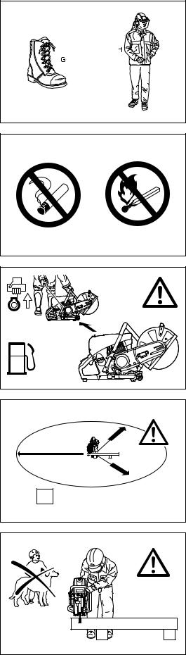
-- Portez toujours des chaussures ou bottes de sécurité (G) munies d’embouts de sécurité, de semelles antidérapantes et de jambières lors de l’utilisation de la découpeuse thermique. Les chaussures de sécurité équipées d’une couche de protection protègent contre les coupures et garantissent une bonne position d’équilibre.
-- Portez toujours des vêtements de travail (H) solides.
Carburant/Ravitaillement
-- Avant de procéder au ravitaillement, rendez-vous dans un lieu sûr et plat.
N’effectuez jamais le ravitaillement sur un échafaudage, sur un tas de matériaux ou dans des endroits de ce type !
-- Coupez le moteur avant de ravitailler la découpeuse thermique.
-- Ne fumez pas et ne travaillez pas à proximité de feux en plein air (6).
-- Laissez le moteur refroidir avant de procéder au ravitaillement.
-- Le carburant peut contenir des substances similaires aux solvants. Les yeux et la peau ne doivent pas entrer en contact avec les produits pétroliers. Portez toujours des gants de protection lors du ravitaillement (et non des gants utilisés
pour les travaux courants !) Nettoyez fréquemment vos vêtements de protection et changez-en souvent. Ne respirez pas les vapeurs de carburant. L’inhalation des vapeurs de carburant peut être dangereuse pour votre santé.
-- Ne renversez pas de carburant. En cas de déversement, nettoyez immédiatement la découpeuse thermique. Le carburant ne doit pas entrer en contact avec les vêtements. Si vos vêtements sont entrés en contact avec du carburant, changez-en immédiatement.
-- Assurez-vous que le carburant ne coule pas sur le sol (protection de l’environnement). Utilisez une bâche appropriée.
-- Il est interdit de procéder au ravitaillement dans une pièce fermée. Les vapeurs de carburant s’accumuleraient près du sol (risque d’explosion).
-- Veillez à visser à fond le bouchon du réservoir de carburant.
-- Avant de démarrer le moteur, rendez-vous à 3 mètres au moins de l’endroit où vous avez procédé au ravitaillement de la découpeuse thermique (7), mais en dehors du rayon de projection du disque de coupe (sens des étincelles).
-- Le carburant ne peut pas être conservé pendant une durée illimitée. N’en achetez que pour une consommation à court terme.
-- Utilisez uniquement des récipients certifiés et colorés pour le transport et le stockage du carburant.
-- Gardez le carburant hors de portée des enfants !
Mise en marche
-- Ne travaillez pas seul(e). Une personne doit toujours se trouver à proximité en cas d’urgence (à portée de voix).
-- Respectez les réglementations antibruit lorsque vous travaillez dans un quartier résidentiel.
-- N’utilisez jamais la découpeuse thermique près de matériaux inflammables ou de gaz explosifs ! La découpeuse thermique peut provoquer des étincelles entraînant un incendie ou une explosion !
-- Assurez-vous que toutes les personnes situées dans un rayon de 30 mètres, par exemple les autres travailleurs, portent des équipements de protection
(voir « Dispositifs de protection ») (8). Les enfants et les autres personnes non autorisées doivent rester à plus de 30 mètres de la zone de travail. Gardez également un œil sur les animaux présents (9).
-- Avant d’utiliser la découpeuse thermique, vérifiez qu’elle fonctionne parfaitement et en toute sécurité, conformément aux recommandations.
En particulier, assurez-vous que la meule est en bon état (remplacez-la immédiatement si elle est cassée, endommagée ou déformée), qu’elle est correctement installée, que le capot de protection est bloqué, que le protègemain est bien fixé, que la tension de la courroie trapézoïdale est correcte, que l’accélérateur peut être aisément déplacé, que les poignées sont propres et sèches et que l’interrupteur à prise de courant fonctionne correctement.
-- Démarrez la découpeuse thermique uniquement après avoir procédé à son montage complet et à son examen. N’utilisez jamais la découpeuse thermique si elle n’est pas complètement assemblée.
5
6 |
3 mètres |
7 |
30 m
|
= port d’un équipement de |
8 |
protection |
|
9
30
 Loading...