

Page 1
REPAIR INSTRUCTIONS,
PART 1
1.
Assémb e lhe slii'ener
wilh ñN lasl6n€c. Do NOT
plale
NO'E
fh6 6ngin6 siilf€ning fame
f4tene6 are ONE TIME USE
lasleóers musl be installed.
The aváilable lool, 9994649, cañ ba usd io
hold slifening lEme iñ
lnsrallthe oil
cfo$o@r
Using a lorque w rench, lighle¡ lhe alaching
fasl€néB in s€quénc6 amording lo
pfé$uB pipé
p¡pe
bet)€ tofqu+l¡ghtenlng the
Oil Pump Pipes and
lnslallation
aíachlnq
ONLY N&
posillon
wfile
and lh6
Stráiner
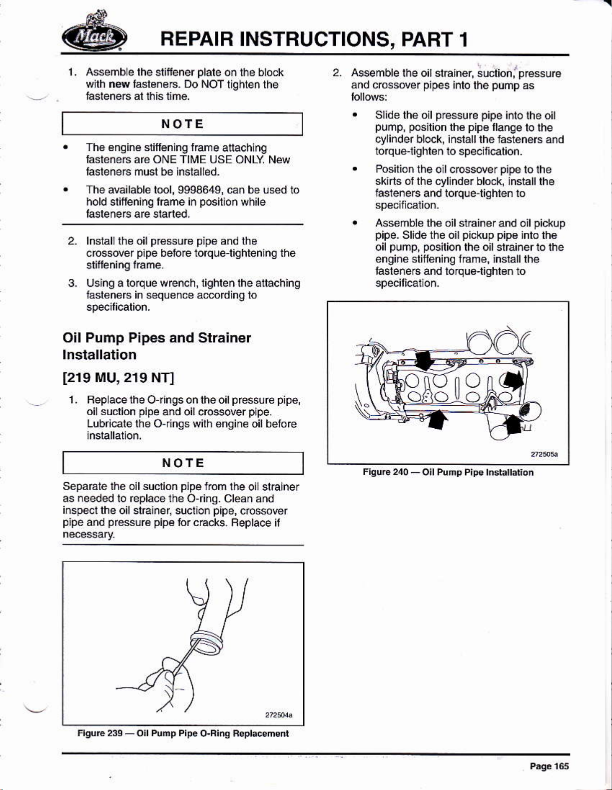
2. Asemblelhe
8nd ccsové¡
slide thé oil
punp, posilion
ct4inder block, ¡nslall the lasténéfs
torqué'lighren
Posilion
sklrls óf lhe cyllnder blo¿*,
hsteneE and lorqüetighten to
¡6s¿mblé lhé otl slrainér
pipe-
Slidé the oil
pump, posirion
oil
én9in6 stif€ning fÉmé, insrall rhe
IasteñéE and bJqué'lighlen lo
oi¡ siáher, ;udioni
pipes
inlo lhe
pessure pipe
lhé
to 6pe6ili@tion.
lhe o I ccsder
púñp
pipé
llanqe
p¡pe
and oil
pickup
rhe oil srfa¡ner ro ihe
pip€
pEs6u@
as
inlo lhe oit
lo lhe
and
lo ihe
lnstall the
pickup
inlo lh€
[219
MU,219
NT]
1, Bepacelheo t¡ngsonlheol
oi! suclion
Lubricate the O-dngswith 6ngine
sépaÉte th¿ oil suclion
as needed lo Éplace the o,finq.
iñspect
prpe
lhe oil stEi¡er, suclion
pr6ssuré
and
pipe
and oil dosever
NOTE
pipé
pipá
ror c€cks.
l¡om
p¡pe,
pressúfe pipé,
plpe.
oilbetoe
!hé oil stEiner
cléan and
cos$@r
Feplace il
o
o
o
o
Page 2
FEPAIR INSTBUCTIONS, PART
1
Front Eng¡ne
1299
Gvl
Support lnsta¡lation
1- ¡l €m@d, dsenbte the loni enqiñé
suppo mounring bfaokel ro rhe
block and lishleñ hsleneB lo specili€llo¡.
qlindef
NOTE
Tho bdckél also setu4 as lhe ¡/C @ñpre$or
2. Assemble lhe lon¡ engine suppo.! onlo lhe
moudád bBckéts a¡d iñslaLlthé sit
bl@k
3. Using a lolque wénch, tghle¡ all lasteneA
iñ sequen@ ro sp6ilicarion.
Pr6r.
l2
2. Apply á 2 mm
lvAcK approred sal¡cone seálañl to thé r6ar
lácé
lhé der
ol
(5/g
lnch) bead
ac@ding to the
sp*ar stes 170
ot
patern
Crankshatt Front Cover and Seal
lnstallatlon
[211
JBl
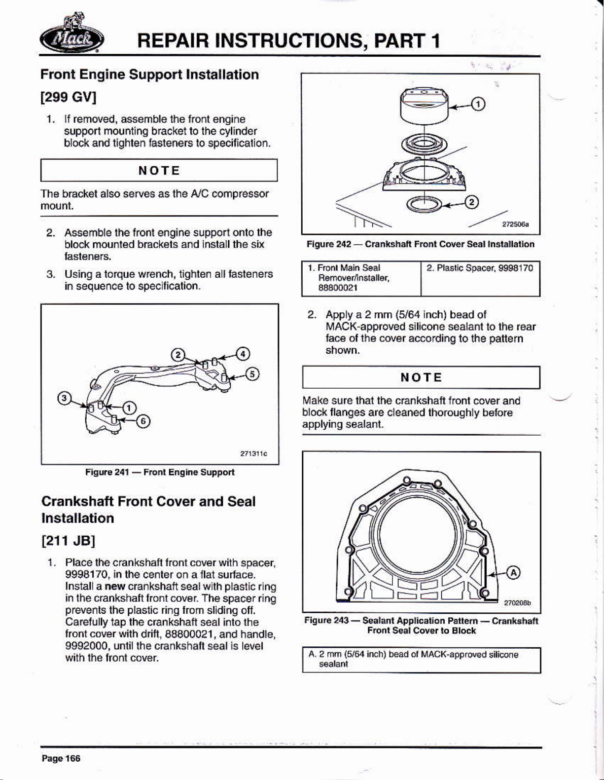
1. Pla@ lhe cánkshaft lronl cowr wftn
9998170, in lhe cenler oñ a llal sufface.
lnstal
¡n lhe cánkshalt lrcnt mr The
prryenls
carelully lap the crankshatt seát intó lhe
lronr co€r with
9992000, unlii lhe
a
ns
cErkshaft seal wllh
plás1ic
the
fing lrcm
d tl, 68400021
cEnkshaft *d ls le@l
plasl¡c
spacer ¡ng
sljding olf'
and handte,
,
6pacer.
rlng
NOTE
Make sure lhai the cÉnksháft lonl
block tlanges are cleaned thoroughly b6lor6
a 2 mm
(re
inch) bead o' MAcK¡ppr@3
@ver and
siticone
Page 3

REPAIR
INSTBUCTIONS, PART
1
3. Within 20 minulés
inslall lhe font wer to the éngine bl@k.
Cenle.lhe cEnkshaf lóñl 6v€r againsl rhe
c.anksháf
lnrall lhe
4.
usinq lhe
font @wr Note that the6 a¡€
For éarliéf typé
lnstallal¡on ¡ñstructioñs ápply:
lnsla
ll Ih e bo¡is wiihoui 1¡ghGñh g lh em
Using a stEighrédgé
the cder is flush wilh the leer édaé
ol sealanl appl¡calion,
pl4lic
fiñg.
(a),
rhe
tol¡Nirg
ru e, make sure
ol
F.uE245-FE6vdrÓiquós¿qenc8
5. RemoE the
hub. Dn@ in lh6 cÉnkshaft
48400021
d ft bónoms
plaslic
ring fom the crankshan
sea wilh dr¡ll,
and handle, 9992000, unlil lhe
,
against the c€nkshatt.
For lárér
rype
(B),
the iolrowlng
irsl¿llát¡on inslructoN
lnslallthe bolls in bolh boh ho es lhal
gn
al
Tiohtén by hand so lhállhe
lúed,
cove¡
lhé
lo lhe @@t
lnsiallihe remaininq bo[s.
NOTE
For lho laler
smallerand lhe righr-hánd hole
change
5. Us¡ng a torque wén.h
capscrews iñ sequonc6á@dinq
lvpé @ver, the tef hand hol€ is
lows
a
the laler mrer io bé coreclly
lighlen the
apply:
posltun.
cder is
is ovat. Thts
lo
Page 4
BEPAIB INSTRUCTIONS,
PART 1
Tim¡ñg
1211
AAI
Gear
Plate lnstallation
NOfE
Roiale the engine b ock so the rear sur'a@ is al
NOTE
fthe cyr¡nder head is lnsralled atrer lhe riminq
geaf plale
cylinder
h€ad ár€a uniil Éády lo as*mble lhe
1. Clean lhe limino
Clean lhé @ñlacl
blockánd cylinde¡heád. Bém@ealing
compolnd fom rhe
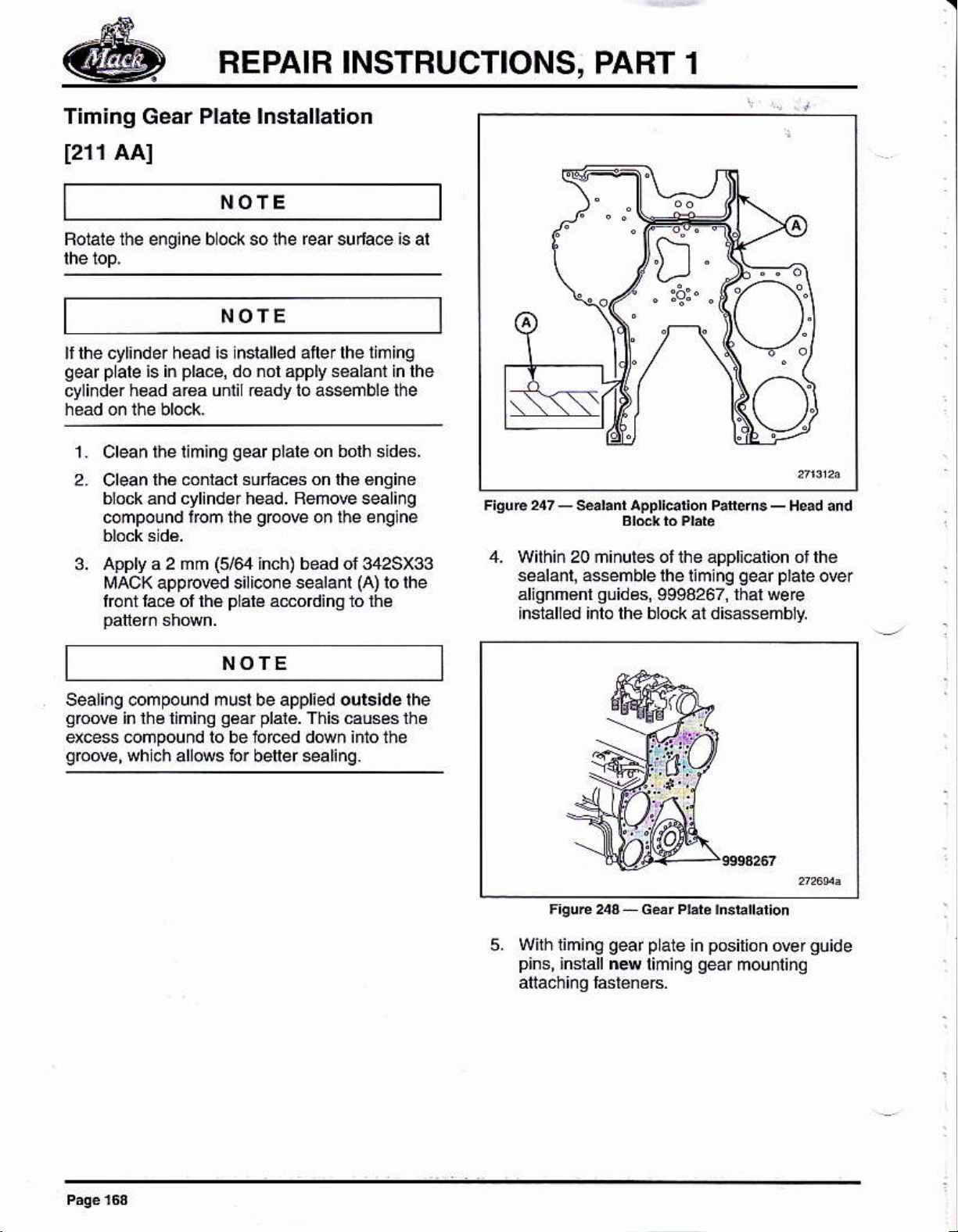
Apply
3.
MACK appr@d sili@ne sealanl
lronl laÉ of lhé
i6 in
2 mm
a
pla@,
6/e
do nol apply séáhfn in lhe
qear plale
sulácés on lh€ €nqine
grcoE
inch) bead ol 342SX33
plal€
on bolh sidés.
on rhe englne
(A)
adording lo lhé
lo lhe
4. with¡¡ 20 ñinutes ol ihe appli€iion ot lhe
sealanl¡ assemblelhel¡ming
¿lianm€nl
lnsialied lnlo lhe bloók at disassembly.
quides,
9998267,
gear p¡aie
lhal wee
orer
NOTE
Sealióg @mpound musl be applied ours¡de the
aoM
excess @npound lo be iofced down lffo the
sb@,
in lhe limino
whicn
a[@5 b¡ betersalinq.
oáá¡
plalé.
This causés lhé
Wilhliming
5.
pins.
gear p
inslall n4
ate iñ
liminq
posilion
qea.
@rguide
mounl¡no
Page 5
REPAIR INSTRUCTIONS,
PART
1
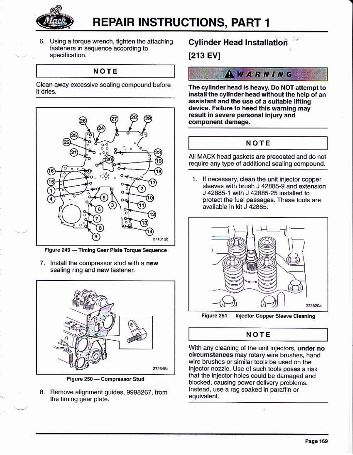
6. Uslng a iorque wénch, tighián
lasléneF in sequen@ ace¡di¡g lo
lhé afia.hing
NOfE
Cl@n away excessive sealing compóund betoré
Cyl¡nder Head lnslallation
[213
The cylind€r h€ad
¡mtatt lñe cyt¡ndér héád wiihout
áasisiánt
dd¡@. FsiluEto h*d
r6ult ln sevée
EVI
b heavy. Do NOT alléñpl to
and lhe us ol a suit¿blé ¡ifi¡nq
thls warnlng may
personal
¡ñjury ánd
the hetp ot ar
NOTE
all lr¡acK héad
g*k¿ts
equire añy lypé ot áddnional s6¿ling
1. lrnéc¿ssary
sle6v€s wilh brush
J 42445 1 w¡th J 42445-2 5 :nslalled lo
pfolécr
aúilábl€ in kil J 4245.
clean lhe unit injetorcopper
lhe fue
paseges.
pÉ@ated
arc
J 428a5-9 and extens¡on
fhess bols á16
and do not
compound,
7. lnslall the compressr slud wnh
sealing ring and n4lasle¡el
a. Rémore alignment
guides,
9994267, Ióm
a
new
Fieure 2sr hj*br
c¡pFr srp{e cr¿án¡nq
NOTE
Wilh any
c¡tcuñsláncea may
wife brushés orsimilarl@s
inieclor
thal the inj¿clor holes
b ocked, eusinq
lnslead, use a Éq soak€d ¡n
cleaninc ol lhé unit iniéctoB,
@lary wúe brushes¡
nozle. Usé ol such rools
@uld be &maged
p@er
delivery
u¡der no
hand
be used óñ th€
poses
probrems.
páEf
a ns k
and
n
or
Page 6
REPAIR INSTRUCTIONS, PABT 1
2. lnsiall fuél lnlector boé
Ensuro thal ths €ngin€ block ánd dtrk
clean and iree lom any dirt,
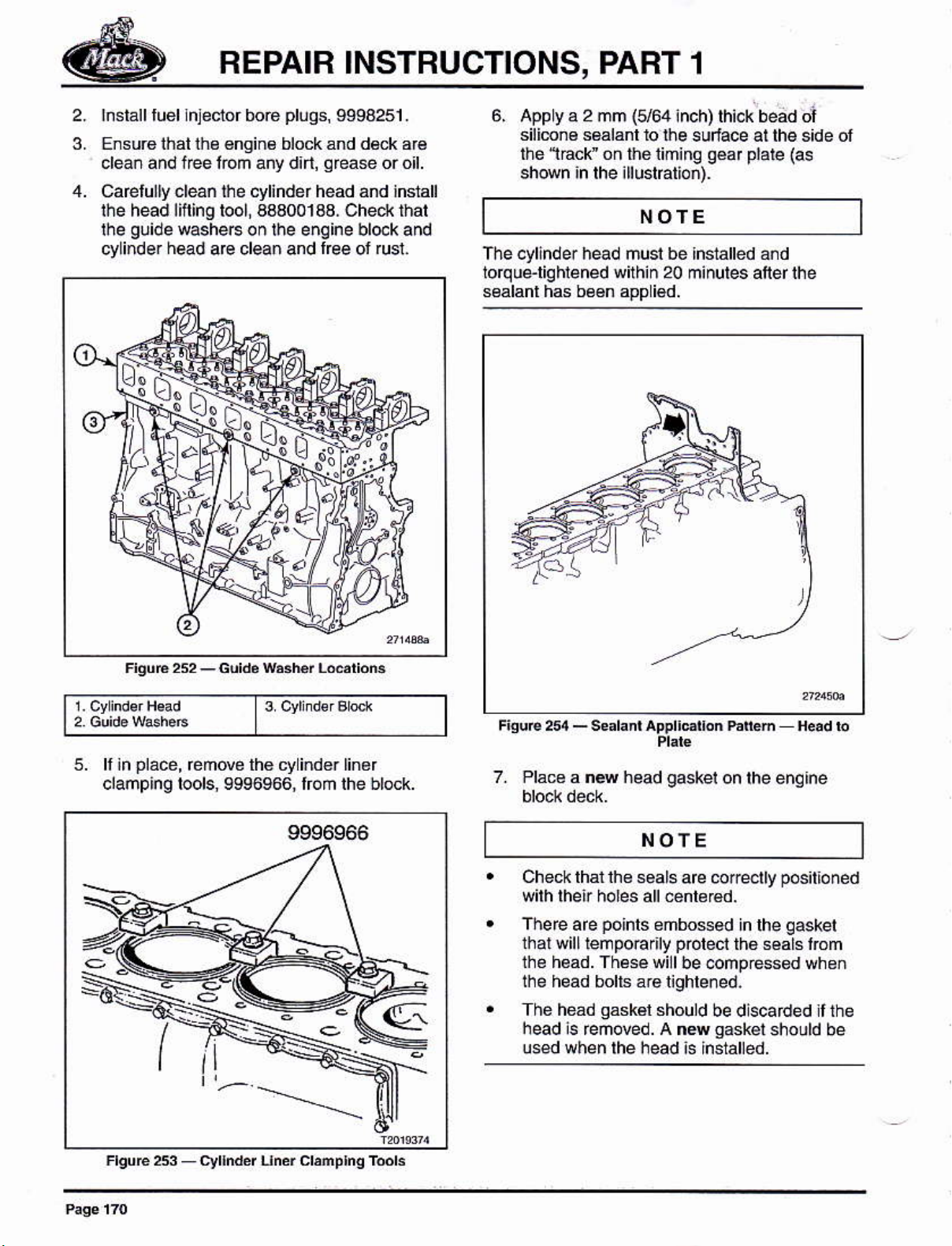
Caelú¡ly ¿léáñ rhe cylindd head and indall
the head lifting tool a3a001aa. ched< that
guide
ihe
cyli.de.
washeF on lhe e¡qine bl@k and
head
aE clean and
plúqs,
lree
9994251 .
qfeae
or rusi.
ffi
*fl3fi
ar€
or ol.
6,
App y a
silimn6 s6álánl 10
thé 1ácr ón thé liminq
sh@n in lhe illuslalioñ).
2
mm
(164
üe sudace at tho s¡de ol
NOTE
Tlre cylinder nead musl be
ioq ue-liq hrened
sealanl hs be6n app i€d.
wilhin
20
¡nch) lh¡ck bead cil
géar plate
{as
5. ll in
Place,
clañping lools, 9s96966, Iom
éñde thé cy ind€r
9996966
FlquE253_cy[ddln¿rcl,mplnqTml3
FiguB254_€e¡l¿nlApplldl.nh¡MH¿adb
a ns head
gaskel
on lhe enq¡ne
NOIE
Check that lh€
wilh lheir ho¡es all €ñt¿Bd.
There
lhal will lempoErfy
thé h€ad. Th66e wi I
the head bolls a.€ lighlened.
The héád
head is Emoved. A nN
u6ed whén rhé héád is lñ$ánéd
are
seals are coreotly
pohls
gásk€l
embo$ed
polect
be @mpÉss€d wheñ
should
be dlscaded ilthe
sasker
pos¡l¡oned
qasket
in lhe
th6 s€als ióm
should be
Page 7
REPAIB INSTRUCTIONS,
PABT 1
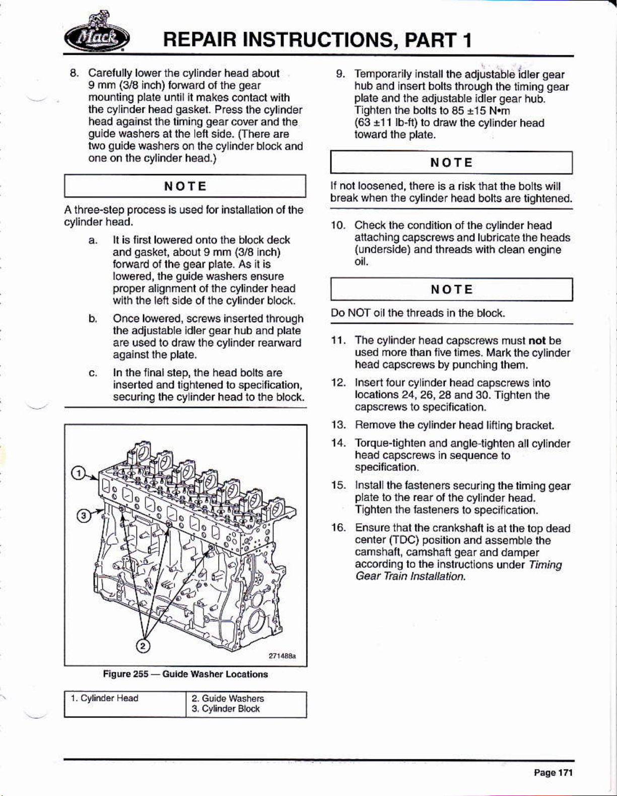
a. Caelllly lowerñ€ cylndér hsd
mm (3ts
I
mou¡ling
the cylind€r h€ad
head againl lhe liniñg
guide
guide
lwo
on6 on lhé cylinder head.)
inch) lotuad ol thé
plale
unlilil makes co¡lácl wilh
gaskel.
washeB ar rhe efi side.
Pfe$ lhe cyllnder
g6ar
corer and
w$he6 or lhe ctlinder block and
ÑOTE
A th@-slep
prcce$
ll is li6l l@e@d onro lhe bl@k dek
qásket,
and
bNad oi rhe
Iowered,lhe
pópd
wirh rhe bn slde ol the cyl¡ndef block.
O¡ce lweed, screG i¡serled lhouqh
thé adiustáblé idlér
is used tor inslallalion ol lhe
about I ñm
geaf plare.
quide
washeB
alignñé¡l ol lhe cyliñdér héad
qéar
a€ used io draw lhe cyliñder Éafrard
ln lh6lnalsláp,lhe head
inserted and tighlgn€d lo sp€cllicalion,
securinq lhe cy ¡rdef head io ihe block.
aboul
qéár
(Ih€f€
(3/3
hch)
A5 ¡r is
ensu¡e
hub ánd
bot6 are
lhe
a€
plalé
L TeñpoÉrry rnsrall
hub a¡d lnsért bolr€
plare
and rhe adjlstábra idre.
Tighléñ lhé
(63
i11 lb-ñ) lo dÉw
bolts b a5 +15 N.m
rhe adjosrablo idr€r
lhrough the lim¡ng
gear
the 6ytlnder head
q€ar
hub.
NOTE
h@d botts aÉ tightened.
10. Check the úndilion of lhé cfinder head
anachi¡g €pscf4s and lub¡l€te the heads
(undé6idé)
añd rh€áds with
crean engine
NOTE
Dó NoT o r rhé rhreáds in thé hr6rr<
11,
The cylinder head cap*rews ñust ñot bé
used ñ016 lhan fi@
head @pscBm by
12. lnsert lour cy indér h€ad capsc€ws
l@alions
mpsc@ws
24, 26, 2a a¡d 30. Tighlen
to specil¡cation.
times. Mark the cylinder
punchi¡g
lhem,
lnto
lhe
qear
ffi
13. Remo€ lhé cylinde r
14. Torque-lighlen
head cap*rews ñ s¿quén.e
lnslal
15.
p
lhe lasle¡e 6 secur ñg lhé liminq
á16 to thá rear
¡ghleñ lhs lásle¡eF
Ensure that lhé c€nkshalt
cenre¡
camshalli
(Toc) posilion
ác6rdi¡q ro ihé inslrucl
a nd angtet¡ghten att cyt ñdé I
oi lhe cyl nder h€ad.
camshail
head llfr ing b racksl.
io
to specifcal¡on.
is át th6 lop d€ad
and 4sembe the
géar
ánd dámper
ons und€r Itnt4g
gear
Page 8

REPAIR INSTRUCTIONS, PABT 1
Camshatt lnstallation
1213
Thé cáñ3hált ¡s h4vy. Do NoT álléñpl to
CHI
¡nsláll lhé cañsh¿ll wilhórd thé hélp ol ar
ássistant or thé use ol a sulable flting
de!¡ce. Falture to heed thls
resut ¡n severe
peBon.l
war¡¡ng máy
injury ánd
ll rcmov6d, iñslaLlthe canshati bear¡ng
saddlesiolhe odginal
lap lhe bea ng saddles onlo
using a soit-la.€d haññé¡ until lully sealed.
lnsenlh6 €mshafi low6r bearings and
2,
appry aceñefous c@1n9 ol clean engine oil
lo lhe camshaí
3,
Make suré
lowér beárlng saddle. The beaf¡ng insefls ai
béarlngs.
lhe¡€ b a b¿áing insrt on each
lhe No. 7 camshat
posilions.
jouhal
Ca€lully
guide pins
th e
haw lnlégEl
6,
lnslalllhe camshai uppe¡ b€aring
iñto lhé.ánshafr bea ñg caps, ¡úbricále thé
inseds
beannls añd l¡siall lhe beariñg caps lo lhe
respeclive bea¡ing saddles. Use a soflaced
mallet tó séal thó b6áriñg €ps d$ th6
lnsen and hand i¡gh1en lhe dhaust slde
beari¡g cap
bolts
and lighien lo
spd¡licalion. Fjnal liohl€nina lo lh€
speil¡ed lofque %lue wlll be done laler
when rhe rccker arm shafi is insralled.
3,
¡¡stallrhe bearing ep
r€qukád) al lh¿ numbér7ánd lhe number
p¡ess
i@r
(1wo
bea ñq €ps ás sh@n in lh8 illuslÉlion.
1
4. C ean and inspect the canshalt usinq
solwnl and comp@sed a¡r
Lower
5
lhe
lifiing lool, 45109034. Folalé lhe
bY hand io énsure tho emshaft is nol
b¡¡ding on the l@er beár¡no saddlés.
ihe camshafl caretully into
lower
bearlnq edd es and €move lhe
place
camshaft
on
NOTE
fhe lootis used when adlústing thétimtng
backlash when
lhe ocker shafi assembly is ¡ot
g€ar
Page 9

REPAIR INSTRUCTIONS,
PART 1
Timinq Gear Train lnstallatlon
NOfE
Apply á liQhr coal
DO NOI ovdlightú thé Mlkg awé
lastenets when instalkg añy ol the
t¡n¡ng
qeat
ol clean engine oil lo all
^caurroN
géaÉ
tak. oveñjgl,ten¡ng the hstaets
an @M sriwad fh@ds i¡ lhé ct4indd blúk.
1. As*ñbl6 á r4 o dnq on lhe chnkshafr
2. Apply a l¡lm ol ol io lhe O ring and ssemble
lhé chnksháí
Leaw two fáléneÉ lo6e
luming lhe cEnkshatl wilh
gáar
on lh€ c€nkshal hub.
NOTE
pa¡ts
ln the
3. Assembb rhé adiusrábré i¿b;
Figurc
and laslereG
3.adjGbbre dsGs
260), hub, bushins, lhrusl washer
plate.
Hand llohi€n lhé
adlus* rd!¿r &ár
ráñden Puñr
t6
FisuE e
o¡ the
-
I Gd,
7.Af
|
hec<f D,ñe
b@loem
Df 6
3 in
FiguÉ259_cEnk3hliGsrlaHubtrséñbly
4,
Chéck l¡al lhe @mshatl is
posilioned
at
Page 10
REPAIB INSTRUCTIONS, PART
1
Align lh€
leeth 10 sláddle the al¡gnmenl hole in lhe
riming
gear
Figur€ 262- lnslall
J 4451,1-1?\, using f¡ositior B of th6
p
ate 1oo lo scufe the camshait
punch
geaf plare
wirhoú lhe
márks on lhá camshaft
and inrallrhe camshan
peras
d
1ie
clamp
shan n
plate
geá¡
géa¡
lool,
gaugé
to the
úmshalr and loosely inrall the rwo
7
Femove
lool from
v bdl¡on dampgrand clamp
lasleners- T¡ghlén thé lastenec io
lhe aliqnmenl
camshatr
rhé
pln
¿nd cl¿mpplare
gear
and lnsrall rhe
plale
using n4
NOfE
Mafk the bolrs ro aid ln righrening rhe borts 10 thé
degr¿e rclalion
a. hselta0.1 mm
gauqe.
slighr
Tiqhten ihe bolts bV hand onht
sp&ilicalion.
(0.004iñch)thickhess
Adjur rhe idler
pr€ssu€
onlhé lhickn6ss
geaf
so thar thele is
gaugé.
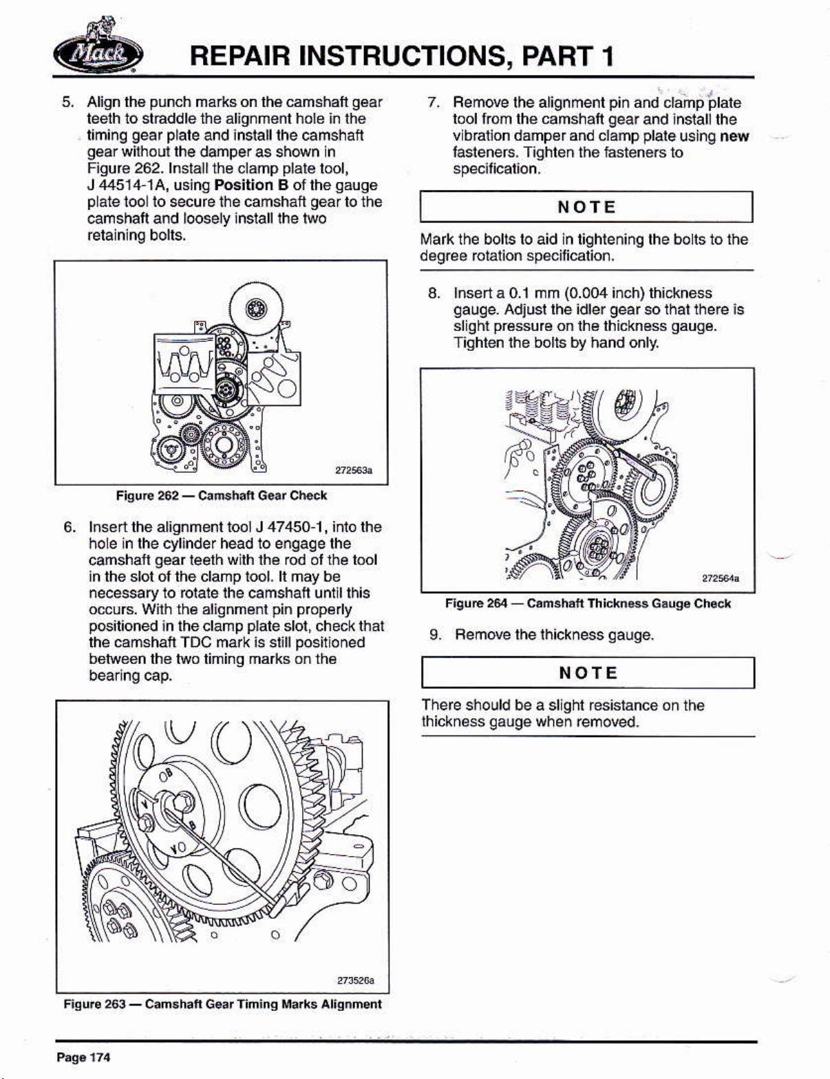
6. lnsed the alignmenl lool J 47,150.1, iñió lhe
hole in lhe cyl¡nde r hed 10 engaq e lhe
cúshatl
in the slol of the clamp tool- ll may be
necessafy to forare rhe camshafr unul rhis
gear
omuB. Wilh lh6 alignménl
p6ilioned
lhe camshail TDC mark is sl¡ll
¡n theclanp
bo¡reen lh€ lwo limi¡g mafts on lh6
¡eelh
w lh lhe ód
pin prcpé y
plale
sloi, checkihat
po6ilioned
l¡e lool
ol
9. Femde lhelhickness
t'¡oTE
a sllghl resislance on th6
qauqe.
F¡4uÉ263_can.h¡fG.¡l'in¡iqlla*s^liqnmnl
Page 11
REPAIR INSTRUCTIONS,
PABT
1
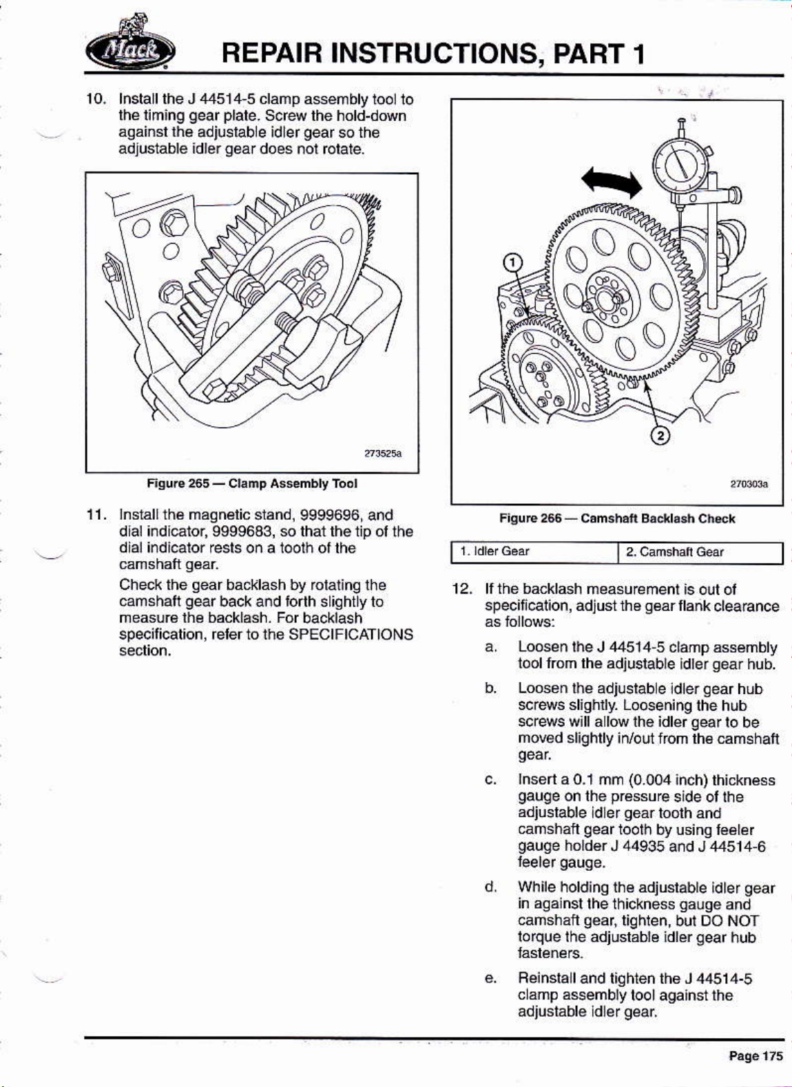
10. lnslall the J
thé timang
asainsl ¡¡a
adluslablé idl6r
'V66
,1451,1,5
oear
adjusrab e idler
plate-
q6a¡
clamp
S6re the hotd-down
doés
asémbly tool 10
gear
s the
nol rctaie.
11. lnsrallrhá maqnálic sránd,
dlal i¡dl€tor, 9999643, $ that lhe 1ip ol
dial irdi€lor resls o¡ a 1@th ol thé
Ched< the
@mshati
measuÉ lhé backlash. For
specilicatton, éler to ihe SPEctFtcATtoNS
qear
bacJilash by rotalinq lhe
g€r
back and torrh s iChtly ro
9999696, and
backlash
th¿
12- ll thé backldh
specif@lion, adjust th6
Loós¿n
iool rrom rhé ádjustable
Loossn
lhe J 44514 5 ddp ássémbly
r¡¿ adjustab e ¡d¡er
$r4s slighlly. LoGening
sc@s w¡llalúihé idlérqearlo
mov€d
¡nsert
gauge
adjusrable
cañshafl
gauge
Wh ile holdino th€ adjuslable
in aoa nsl
ۖshaft
lorque lhé adjuslablé idler
slighlly irvoui nom lh€ ám6haÍ
a 0.1 mm
on lhe
hóldér J 44935
measurement is olt ol
llank
sۇr
(0.0er
prássue
qéár
ld er
qear
toolh
loolh by using lۇler
a¡d J
the th¡ckne$
géar,liqhlen,
cleaBnce
gear
ldrer
Oear
the hub
inch) thicknése
side ol the
and
,t4514,6
ld le r
qauoe
but DO NOT
ged
hub.
hub
be
gear
and
hub
Fein6lall and tiqhien th6 J 44514-5
c 5mp a$embly
tool against the
Page 12

REPAIR INSTRUCTIONS,
PART 1
I Remove thé leeler
adjustabe dler
g.
Fecheck
spécilied b@klashallained¡ repla@
6ach adiuslablé idlér
with ns and lighlen the scrows to
spe¡licarion one ar a rime so rhe
anained backlash is nol d¡slurbed.
lhe backl4h, Wilh lhe
gáuq€
gear
and camshán
aear
13. rnsiarlthe inrermediare idle¡
gearsel
(2)
to lhe timing
gear plare,
from lhé
hub M.ew
(double
idLer)
us
nq
15,
Tiqhten lhe inlemediale
ér)
id
mounl¡ng bo¡ls in seque.ce to
seá6ál
(doutlé
16. lnslalllheauxiliaryidlergearonlothétiñino
17. Bemovelhobea
45109204.
Unit
1221
lnjector lnstallation
GPI
og
cap
pre$
tools,
NOfE
€used, il
1. f not
pr*
sleeve, J 42435-25, a¡d clean the unll
injeclor mppér dé4é
ously
pericrñed,
wilh
musl
be lited
insla I
lhe
app@priale
lo lhe
prol€clive
FisuE 2t rnkrdúr. ¡dr$
|
14. Checklhalnté idlér
the markinqs on the crankshafi
gearmarking
(eude
6 r eñtumpDre
rdre4 G¿'rd
allg¡s with
leelh.
oeár
ir
Frquc te uñn hEdor
Afér cleaning
the inside sulace ollhe
bonom sulace wh6ré lhe injeotor
Any
¡emainir
and musl bé
indicaton ol a discrepancy
aboul súlabilityoflhe sleere lor réuse,
lhe @pper deM, carelully inspe.t
g
contaminalion is u
removed. Also, if lher6 is any
coo@r sreeve creaninq
NOTE
sleeve, espécs ly lhé
seat is ocaled.
na.ce
lhal ra¡ses conceh
olabte
repta@ il
Page 13

FEPAIR INSTRUCTIONS,
PART 1
Betore
rsquiréd to
Berc're doing ar'y c éaning, rhe injelor
inlel and oullel
connec¡or opening musl be covered lo
prdé¡l
pfo@ss-
¡¡sialled ¡n lhe lnlecior Relérto'uNlT
INJEoToF oLEANING'on
3.
Ren@ lhe boe
9S94251.
FiquÉ 270
1 uni¡ lnlsdo' Prcrdion
Busing añ i.jector, cle inq
€nsure suilability tor éuse.
ports
ánd lh6 el€crical
dnlminarion lrom
Also, lh€ré musl
proieolion
Unft rn¡dor Borc PEr€dion sre#
-
lhe cl4ning
no Lower
be
pag6
deM,
lr.'rnirlnlebeE
js
tuel
o{ing
244 lor
0
FsuE 21
Somé ea
orjginal design copp€r déms with iniegEl
y pbduclion
laised bead ar rhe bonom or rhe copper sr66vé.
rhis désign doés NOT
between lhe ¡njecior tip 5nd the
These oriqinal Eised¡ead d6lon copD6r
sledescan b€ idénrir
gbove
The curent
@pper sle4esi wh¡ch reqúi€ me
sásher) ár lhé
lwo
al all around ih8 upp¿r circumie¡ence,
prod
groov€
áround th¿ uppér circunle¡en@
hFdor Nde G*H
ÑOTE
MP3
engines ced lhe
gaskel
use a
@pper slewe,
ed by a single
uclion 'flal-botom'
gask€t (llat
iniécrór rip¡ can be identmed by
washeD
llat
groo@,
design
orno
ol
4. lnlallñ6w O{ings on lhe
.
Upper nnS larSé dlamelor, viol¿l
.
Lower ring smalldlañ6i6r, violál
Lubr¡€¡e
5.
inj¿cror boré wilh
hstarr a ñe inieclio¡ noz
washer)
push
seated againsr lhé bofiom
NOT
secure lhe
ñust bé inslalled
pojections
ot lhis
boih Ojlngs and fis cyl nd¿r head
clean eng¡ne o¡1.
on the i¡jéclor, usinq hand
il
@. lhe l¡p and down uñii it is fully
géas6
use
gaskel
or any olher
gaskel
(srippé6)
to lhe ¡¡jetor the
dry Three sñal
on rhe inside dlameler
rctaiñ il to ih€ injéclor during
injecloras
unil
gaskel
e
ot the injecror Do
{ital
lorce to
nale a¡ lo
gskér
F¡sur€2 copF.
srd.
tshwn
¡snmd ror
Page 14
BEPAIB INSTBUCTIONS,
PABT 1
NOTE
A rwied
rubber maling for impMd séaling was
implemenled ln
2003. Serul.e replacement
rubber coaling, DO NOT remove lhe rubber
The
g4kel
qaskel
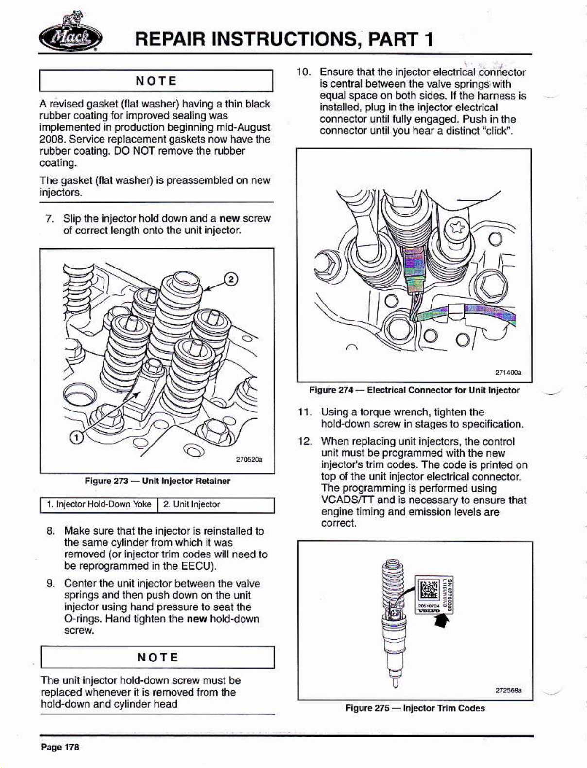
7, SLip lhe injécior hold
of cor€ct l6ñoth oñlo lhe lnll ¡nieolol
pbductlon
(llal
washer) is
(llal
washeo havinq a lhln blac(
begln¡lng ñld-auqusl
qaskels
p€assembled
d@n and á n4 srew
n@ have ihe
on new
10. Ensure rhar thé i¡jdtor érécld€r
is @ntEl betreen thé hh€ springd
€qual
@nnector únlll tully enqag¿d. Push in
space on borh sides. ll rhe hañess is
insiállod,
@nnec!o. unlil
pluq
in lhé ¡njecior
you
electrical
hear a diliñct'tlicl\¡.
o
@nllecbr
wilh
the
Fiore2n-Unft ¡nidorRd¡iner
1 nltuf Nod DM %k
Make sue that lhe inletor ts einstatted lo
same cylinderfom
lhé
reñóred
be rep@gEmmed h ihe EEcu).
Cenler lhe un¡l ¡njector ben@en tha Elvé
9.
sp nqs
inj¿clor using
O rings. Hand lighlén lhé nil hold-down
(or
inieclor lrim óds will need
and rhen
hand
2 udrhFdr
I
which il Ms
plsh
down on the lnf
pre$¡re
lo seal lhe
NOTE
lo
Fioue274-Erd c¡rconn*brbrunnh,¿dór
11. Using á lorqué
hold dowñ scéw in daqés to speflicarion.
12_ When Éplacjhg lnil ini€clo6,
unil musl be
injécro/s ldm
lop olthé unit injector élécl
prcgrammi¡O
The
vCADSm
8ñqiné limina
w€nch, l¡ghlen lhe
lhe @nlol
prcqrammed
@des, The code is
silh lh6 .s
plnled
cal.onneotol
péfom€d
ls
and is ne@ssary lo ensub lhál
and emission levels aé
6inq
:3
:E
on
Thé unil ini€clor hold-down
roplac6d when€vér il is rcmMd l.om lhé
hold doM áñd cylinder head
scra
musl
be
Fisure ¿5
rnjedq frm ed6
-
Page 15

BEPAIR INSTRUCTIONS,
PART 1
NOTE
Due to the Enginé El&lronic
(EECU)
nemssary
PaÉmetórs
enq¡ne ielaled mmponents.
EECU lo leárn the nd @ñpon€nts
behavioi After sedcinq ¡s coñp ete,
pelon
ll rBinstallinq an in¡eclor inlo lhe sané
ocatioñ, rcprooámm nq is not Équned.
sell learn¡ng Épábrity, it is
lo es1 ¡eahed EECU
aftér s¿ruicing
lhé "L¿a¡néd Dala
Cónlol Unit
some
This dlM lhe
Fesef
13. Fepear rhe insrallarion sreps tor the
valve Yoke
t213
NVI
(Br¡dqe)
lnstallalion
NOfE
l6ated
in
yokes
tüáke sufé rhal
Rocker Arm
on
rheir rcspeclive úd€
lhey afe
Shattand Engine Brake
lnstallat¡on
[213
LPI
1. Oillhé vál€
2.
Using lhe lilling toot, a5109250, and an
Gsislanr,
posl¡on
yokés
placé
on ihe inboard sido ol lhe camshaft
and lh¿ camshaÍ
lhe
shall
wilh fockef
NOTE
enq¡ne bÉke, ihe exhaust
an inleg@ ulve
pbpery
lobes
arms in
pisron.
and
yokes
Uséd
Yokes belng returñed 10 seflicé musl bé inslalled
in lhe
same cylinder ¡ocalion lroñ which they
1
, Lubri€le ihe ilp ol a valve stem wilh a small
dop olc éan éngine
2. LubriBr6 lhe
ol clean e.glne oil¡n each o¡e.
have éslablishéd
oil.
yoké
so.*ets with a smatt drop
wear
patterns.
Fsu,€22 Fodersh¿fi
a*ñbthdár'dór
t,
3. Femo@
tlghlen lhe mker
lime, *dy across lhe
lhe
tüake sur€ lhal the rocker
pfoper¡y
béai¡gcaps.
ongin€ bEké, ¡em@
bands oflie slaps) secufi¡g
lhe titling bot. Then,
arm shatt boils á Inb
shail does nol bmme dislórred bént .r
NOTE
arm shan is sealed
guide
ln ihe
On engines equjpped wilh
dowels
lhe fesiáinls
IDB
Fódef
a*mb y
shar
i¡statt and
enti€ shatt so thal
ol the oamsháft
an
(rubbef
lhe exhaust Mker
al a
Page 16

REPAIR INSTRUCTIONS, PART 1
7. Torqué-lighlgn and
camshaft beadng €p añd óckér
anqle-lighlen all
an
shal
bo[6 in sequence a@rdlno 10 spédfcaton.
NOfE
The bohs have llmired reusabrr¡g and must be
(A)
ma¡kéd
iñslalled i¡ sedice. Bolls wilh lour
when remNd he been lighlened live i¡mes
wilh a
punch
áách limé lhey
punch
ae
márks
Lub.icalé lhé ó.k€r arm bl é8.
lnsen
5,
F¡gúre 279) lhóuqh the shafl, camshan
bearing cap6 and
üe bng
lasleneG
inlo
(Nos.
lhe ctlinder head.
8-20
in
g.
Feplace
6nsine b@ke
eno¡ne báke) oro now adaDier
lhe O{lng al the botlom ot lh€
conrrcl€@
(¡f
equ¡pped w¡rh
NOfE
On eñgines withoul th¿
adapter is used ¡¡
is mounlád in
head ánd is installed
enqine b6ke cofrtrolvdB in sléps S rhrough 13.
fhe
adapler
the eme localioñ on lh€ cytinder
p@¡des
engine bEke, an o¡t ltow
place
ol the oil mnl@l valre. lt
in lhe same mannerasthé
oll to the bckor
shaft-
Page 17
REPAIR
INSTRUCTIONS, PART 1
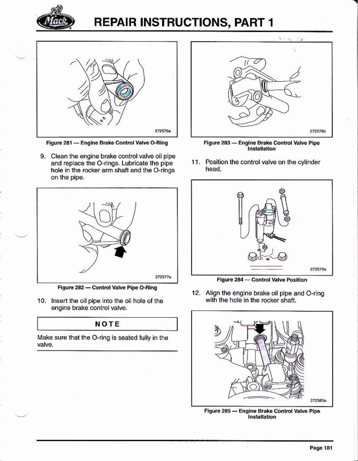
9. Clean
aód @p ace lhe O-nngs, Lubn@le lhe
holá i¡ lhe b.*ér am shaii and lhá Oiings
l0- lnsn ñ6 o lpip€ lnlo lhe
engine bÉke cofrtol valre.
ths €nsins brák€ control valÉ oil
holeollhe
oi
NOTE
plpe
pipe
1 1 . Pos¡tion lhe @ntol válvg on lh€ cylind€r
12.
Align lhe englne bÉke oil
wilh lhé holé in rhé ró.i€r sh.fr
pipe
and Or nq
Mak6 suÉ ihár lhe
Ojing is s@ted lully iñ ihe
Page 18
REPAIR INSTBUCTIONS, PART 1
NOTE
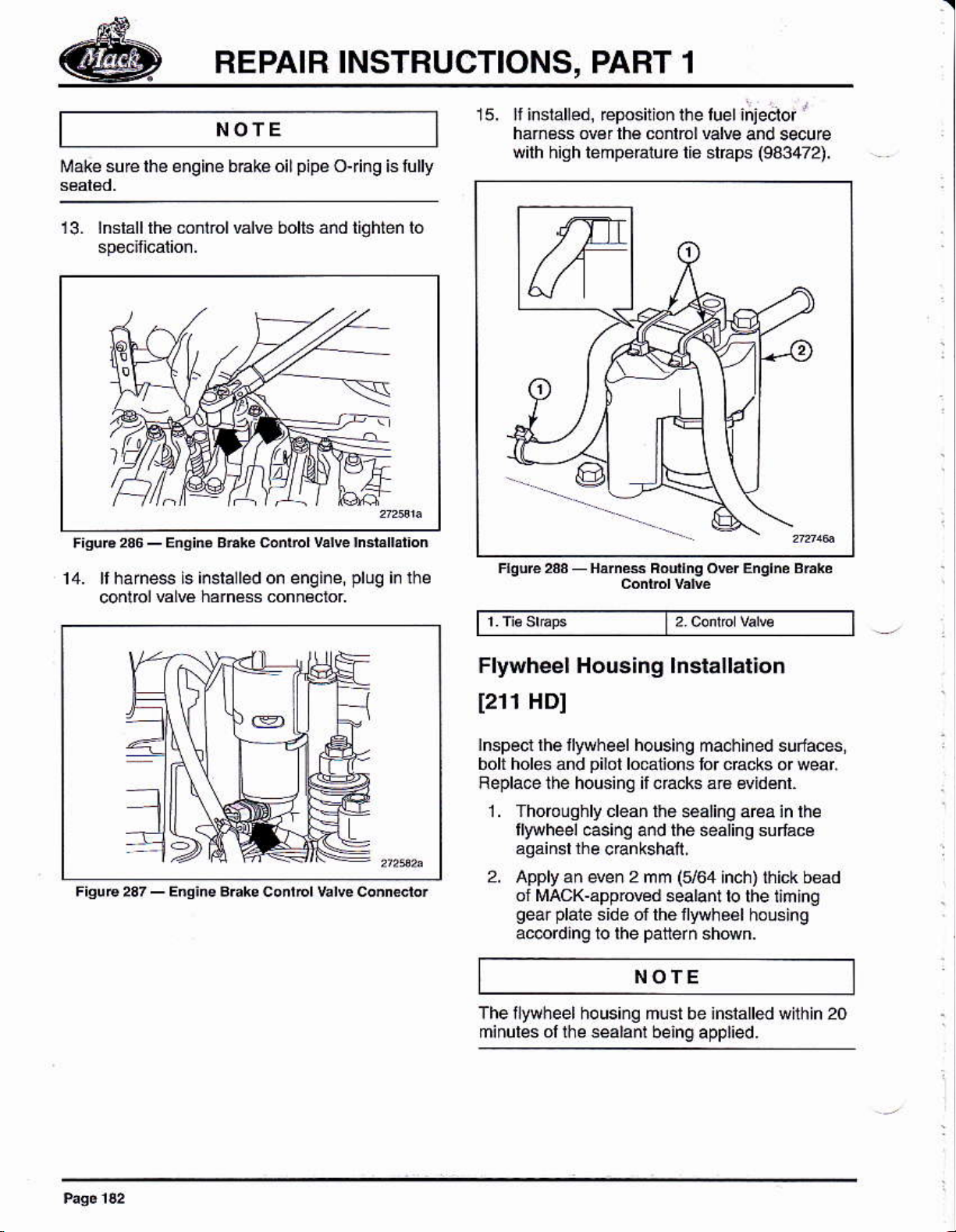
surerhe enqine bake oil
¡¡ak€
13. lnsrállrh6 mnlrolválve bolts añd tighten lo
pipe
ojing is
lully
15. ll
inslalled,
hám€ss ov€r lhé conlrol vdre
qilh
high lehperature tie stráps
eposition rhe
luel
injecior
'
and secure
(943472).
14. rrharnes isinsralledon enqine,
conlbl
EIE harnéss conn€cror
plug
irlhe
Flyürheel Housing lnstallat¡on
f211
lnspecl lhe llyrheel housi¡g
bolt hole! ánd
Feplace the housing il .acks á16 widénl.
HDI
pilot
lo€1ions
1. Thoro!
llywheel
aqáinsl rhe
2. Apply
ol MAcK-app¡owd sealant
gear plaié
ac@rding to the
qhly
clean tho sealing a€a
€sinq and the sealinq suláco
crankshall,
an even 2 mm
side ol the fyrheel
patterñ
ma.hi¡ed suriáces
cEcks
lor
(164
inch) lhick bead
to the liming
or wear,
in lhe
holsing
shówn.
NOTE
The llywheel ho using mu st be inslalled whh in 20
minules
ol
lhe
sealanl
being appl¡ed.
Page 19

REPAIR
INSTRUCTIONS, PART 1
NOTE
F¡q!rc2s9_Flwt¡élfi.Gi.qs€al,i'Ap.ljolion
NOfE
Be
sure lo apply beads oi salanl around the
holos in the bo$6s ás sh¡M inthé
qEphic,
li ihe enQlne Msorg
gear
idler
bé u
bolts, lhe llyNh€61 housing may need
pdaled
lo block l¡re dler
plugandw6herfrcm pluq
followinq
prccedu
nally buill wllh lhe onger
qear
boll hole w lh
kii21090322. Uselhe
ré lo thr€ad lhé hole
a. Using a 3/4 16 UNF x 11.5 lap, lhroad
lhe hol¿ indicáled in Fig!re290,
b. Apply lh€ad locling .ómpound
(Loclrle@
üreads ol lhe
c. lnÉerr rhe
ro spécilicalion.
2z or €qu €len1l
p
uq,
plug
wirh washef and tiqhren
and
ro
rh€
to
a
nslall
femporari
llyryhee hoLs¡ng
y
irstall
glide pins
in lhe l$o lower
mouding holes i¡lhéliminq
3. Wlhin 20 ñinuiés ol lhe application ol lhe
séalanl,
the
4. lnsrl and hánd-t
Femow the te
a$emble the tlylvheel h ousinq de r
quid8
pins
ín lh€nminq
ghlén
the á¡aching
quide pins
plale.
oéar
áñd inslalt lh€
bolls.
5. Using a lolqu¿
bolls in sequ€nc€ ac@din
Femove any ex€s
6
lnsIalllhe limi¡g
7.
housing bohs
wrench, liqhten thé atla¿hinq
gear plate
(ilem
NOfE
llem
1 s€úés lh6
pump
h6m 3 smures
ilyryheel housing and
i¡slallálion inló thé chassis
mounling
and is not insia
lhe rear engine mounl lo lhé
g
lo specif .a1lon.
sealanl.
to the iywheet
2 in
Figúre 291).
powér
sleering and tuet
led al this
will be instalt upoñ
Page 20
REPAIR INSTBUCTIONS, PART 1
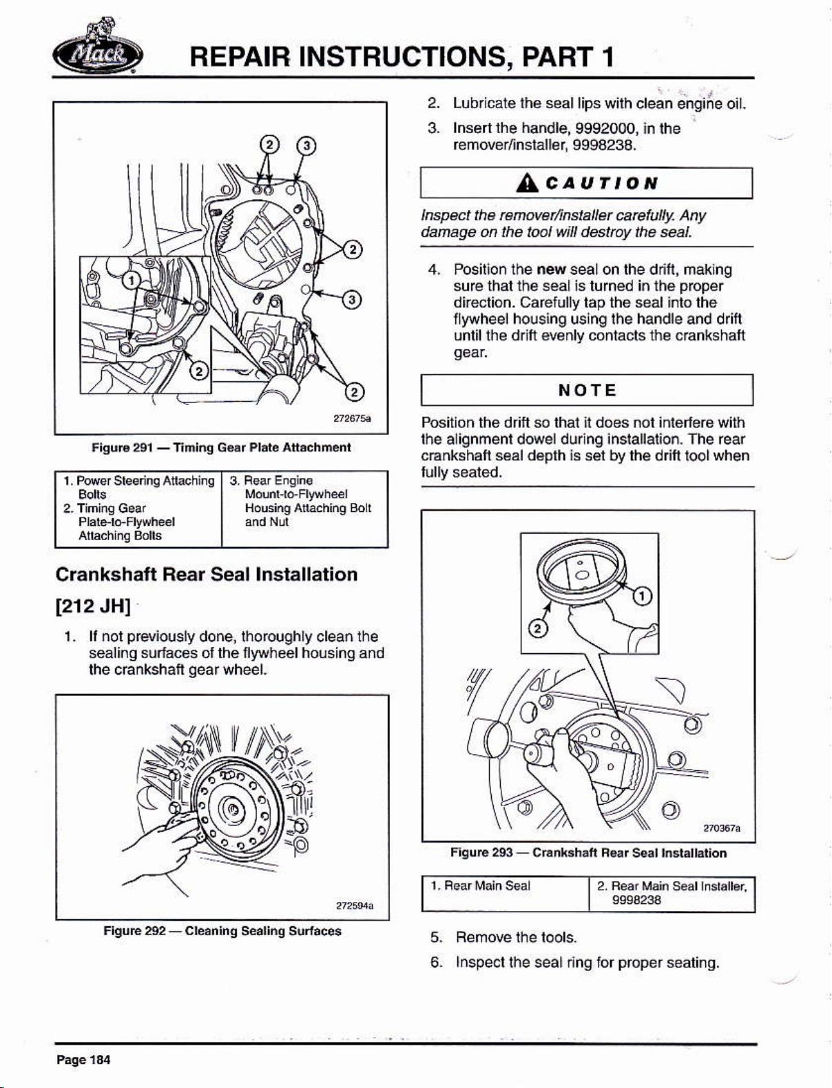
Lubricaté lhe seallips
2.
wilh clean engiÁe oil.
1 Pore¡ sbs'inq Aturrinq
BsarE¡qhs
13.
Mdún, ro Fr!}hel
I
ándNú
|
lnsenlhe handle,
3.
f emover/inslaller 9994233.
9992000, in lhe
AcaurloN
|repe.x lhe rcnNét/¡rstalü
@elully.
datuae ú lhe loal \|¡I d4ttay lhe ffi|.
4. Posilion lhe n4 seal on lhe dn'f, mak ng
sufé thal thé séaL !s luméd i¡ rhé
dkelióñ. cafelully tap the seal into lhe
llyohe el housing uslng ihe handle and d ritl
unlil lhe dr fi e€nly conlacls th¿ cEnkshalt
NOTE
Position the drift so lhat it does ¡ot iñierleG with
rhe alignmenr dowel durlng insrallarioó. The rear
cEnkshaft seal déplh is sél by lhe
d l loolwhen
y
At
pppér
Crankshatt
[212
JH]
1. li ¡ol
sealinq súlaces ol lhe Íyryheel housing and
lhe cÉnkshaf
Rear
p
€viously done, lho
Seal
qearwheel.
lnstallation
rough
ly clean lhe
5.
lnspecl
t2
lhe seal inO ior
Féáf Mañ s¿ar
proper
sealinq.
mratb.
Page 21
FEPAIR
INSTBUCTIONS, PART
1
Flywheel and Pilot Bearing
lnstallation
1212VCl
AcaurroN
AtÍerre ¡fackg,
balance hol6 ón tÉ ctutd1 Bida @]JJ¡6
rcbalañ¡ns by a Mch¡he shop.
vehicles
On
üansmiss on, il may bé néc€ssary 10 insláll
dllferenl componenls lo ihe fywheel relalnlng
hsleneB Feter io lhe Automalic Tbnsmi$¡on
D vé Arsngeménl Assémbly lnslruclions¡
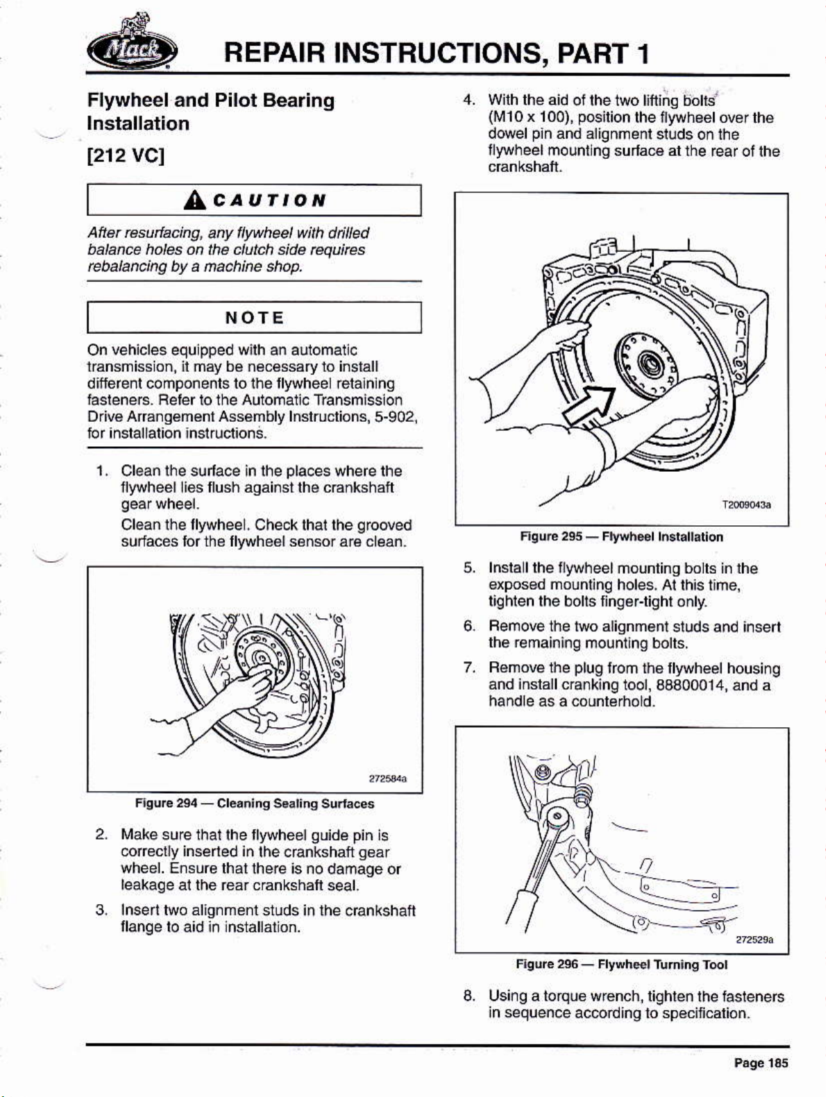
1.
Clean lhe sulace in lhe
flywheél li6 llush ágái¡st lhé c€nkshafi
anyíy hel úth dt¡¡led
NOTE
pped
equ
w¡lh an aulomallc
pla.es
5-902,
where lhe
4. Wilh lhé
(rü10x
dowetp¡n and atignment
f'ryheel mountlng surla€ al
aid of lhe 1wo lifiñg bohs'
pcirion
100),
7
rhe iyvhgérowr lhé
studs onlhe
the ear ot the
\+
)
Cl€an rhe tlywheel, Ch4klhal lhe
surfaces lor the llyuh66l sénsor ará cléan
lüake
su€lhallhe fywheelguidá
@fecl¡y inséled in
wheel. Ensure lhalihe@
leakaqe ai thé éa¡ canksháft seal.
3.
lnserihro áliqnmenl
llanqe to a¡d ¡ñ nstattátio¡.
lhe eEnkshafr
is no damaqe of
sluds in lhe oEnkshan
qroded
pin
i6
gۇr
Fqué 2es
lnsla I
dposed mounlinq
liqhlen lhe bolts liñg¿Flighr only,
6.
Femove the two alignmant
lhe re
BémoE the
and inslall cE¡king1ool,
lhe ¡ywheel nounling bo ls in lhe
main ing mou nting bolts.
F¡Éh*r
-
holes, Ai lh¡s t¡me,
plug
lroñ ths llyryhéel housinq
I
ó,--5'
r.d.lldioñ
studs and ¡nsert
3aa00014, ánd a
8, Using a to¡quo w€nch,
in sequence ac@rdino
Page 22
BEPAIB INSTBUCTIONS, PART 1
,AcauÍtoN
Do tut ¡lghten aqa@nt úM seq@nüatty.
Dokg@@nre
Fa¡luté to h@d th¡s
¡t ¡n meven lwee¡ allgnñút.
@ut¡@ @n @lt ¡n se!ere
@
plug.
n{
cEnking
pllol
lool, lnsérihe
bearing in lh6llywhoel
9.
FemoBlh¿
Using lool asembly, 9991S01 and 9992564,
inslalla
AcauÍtoN
Fot lh¡s eng¡¡e, llo shap ing ¡s Eqúircd on lhe
pilot
b@ n9. Do Nof subs¡¡tute
lhal do nal beat lhe @tred
awliB¡ion. Fzilute tc, h@d ds aú¡¡on ñay
Esu¡t k sete ens¡re danase.
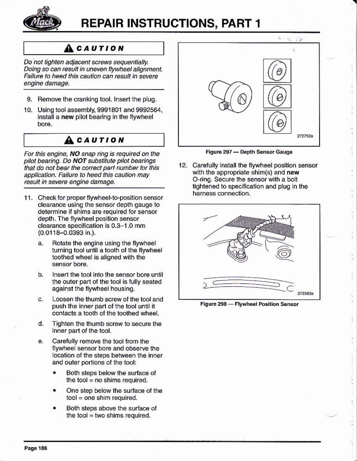
11.
éck
Ch
cleadñcé using the sénsrdelh
delermlne ¡l shims are ¡equ red ior sereor
déplh. Th6 nywhel
cleaÉnce specii€l¡on ls 0.3 1.0 mñ
(0.0118-0,0393
to r
p@pér
llywh€el-lo-positió
pos
n,),
a. Boiare rhe enqine using the lllrvheel
tuñinq lml unlil a lmlh ol ths fwhéél
loolhed wheél is al¡gned with lhe
p¡bt
pan
nunbü bt ¡f'¡s
lion sonsor
b@n@s
ñ senso r
gaooe
lo
@
t@t
FisuF 24
12.
Cárélully
with ihe approp ale shim(s) and new
Or¡nq. S@ure the sensor with a boli
lighléned io spécmcaion
-
jnslalllhe
@'
llywh éél
s€No. Galsa
and
pósilion
plug
sensor
in lhe
b. hs6n ú€ bol inro lhe sener
the ouiér
asainsr the llywheel housinq.
Locen lhelhumbscÉw ol the tool and
pushlhe
conlacls á toolh ol lhe loolh€d wh6¿1.
Tighten the thúmb screw to sécurc
Ca@lully remow ihe lool irom the
llywhoeL sensr bore
ocation ol fte sl6ps béiween rhe inner
and outer
.
.
.
pa¡i
ol the i@l is lully s€ated
inn¿¡pa ót
portlons
Bolh steps bdN lhé suffa@ ol
Ihe l@l
One step bélow th6 surlaÉ ol rhé
Iool = one sh m Équiéd.
Boih slePs abó@ the surfac6 ol
the l@l : iwo shiñs reqúúed.
no shims ¡equned.
=
the lool unli
and observe the
ol the tool:
bo@ until
il
lh¿
Page 23

Pan lnstallaiion
Oil
BEPAIR INSTRUCTIONS,
PABT 1
I21r
NBI
lhe
(0.079
llyvhee¡
plale,
inch) wide béad oi
houslngand lhel¡htho
Alsq appya 2 mm
1 , Apply a 2 mm
lrAcK-apprcred s€lant ar thé *ams
be¡reen
g6ar
mounling
(0.079
seams belweeh thetmlng
plale
inch) wid€ béad ol sáálánl al rhe
and lhe enqine bock.
Aeár
mounling
3. For
plasl¡c pañ
pan
seal inlolhe
Check thal the séal lo@lnq
prcperlyáliqned
holeson
lie mounÍnqfanqé.
appli.alions, ¡nslá I rhs oil
gb@
and seal€d
ol the ollpañ.
tabs a€
jnrh€
locali¡g
2. Applv a 2 mm
MACK approled sealant lo lh€ seam
belwéén lhé lro¡l seál ¿over ánd the blo.k
(0.079inch)
bead oi
Page 24
REPAIB INSTBUCTIONS,
PART f
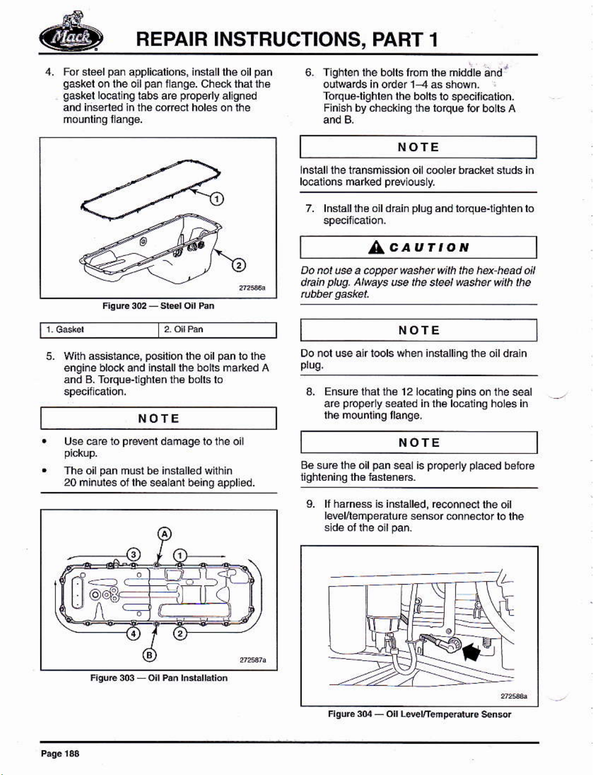
4. For steelpan applicalions, inslalllhe oilpan
qaskel
qaskel
iñsened
and
on lhe oil
lo@1
pán
ilange. check thal tha
ng labs are
.or¿cl
in the
properly
hds on lhe
allgned
6. ¡ghreñ rhe borrs lóm lhé mid;b
dd
l
oul@ds in oder 1 -4 as shówh-
Torqu&lighle¡
Flnish bv ch€ckino the loque
rhe bolrs ro specillcatióñ.
tor bolts A
NOTE
lnsiall lhe tbnsñission oil .oo 6r bEckér studs iñ
l@arions marked
7. lnslalllhe oil dráin
prwlously,
pluq
and lorqué-nghlen lo
LcauÍtoN
Do not u@ a @ppet washet with
ptug.
dta¡n
At$ys
u@ the steel
NOTE
5. Wilh assistance,
engine block and ¡nsrallrhe bolrs ma*ed A
ánd B. Tofquo-r
pGitbn
qhl€n
the of
rh6 bolls lo
pan
NOTE
ca€
Use
The oil
20 minules of lhe sealanl being appled.
Q)(
pr*nl
lo
pan
must bo iñstallod wilhin
damagelolhe oil
to thé
Do nol use alr lools wheñ inslallingihe oild€in
3. Ensurá
popery
aré
rhal ihé 1 2 localinq
seabd inlh6l@alino holes in
pins
on the seal
NOTE
aé suré lhé
oil
pan
seal is
L lf harnBs is inslalled, reconnect
level/leñpe¡alure sensor mnñe.lor
properly pláced
lhe ott
bslirr€
lo lhe
Page 25
REPAIR
INSTRUCTIONS, PART 1
Oil F¡ller P¡peand D¡pstick Pipe
lnstallation
1 . lnsla I a nw O r ng on lhs oil lill lube ánd
inslalllhe
lneallrhé oilfi
tube to lhe s¡de oftheollpan.
lrube lasrenerc and rlghrenlo
2. lnstall a new O dng on lhe dlpsnck tube,
rhen nsrall rhe iube and secu fe wnh lhe
laslen€r lnsláll rhe dipslick.
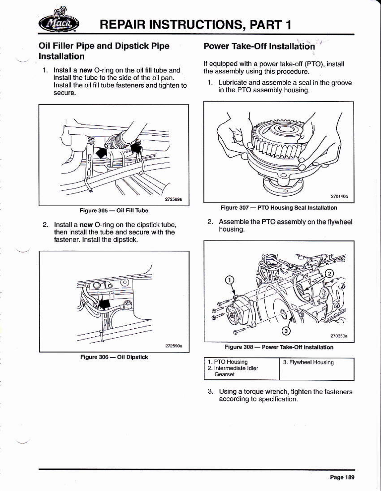
Power Take-Off lnstallation
equipped
li
the asámbly
1 . Lubicale
ln the PfO ássémbly housing.
wilh a
2. ¡Gsmb ¿ lhe PTO
ptuer
lsing this
and Nemble a seal iñ lhe
iakg'off
pbcedure.
ssembry o¡ the llywheel
(PTO),
'
inslall
qrcM
3. Fwheer Hds nq
3. Usingalorquewrcnch
ac.ord ¡. o lo specilicalio¡.
lighlen lhe lasteners
Page 26
REPAIR INSTRUCTIONS, PART 1
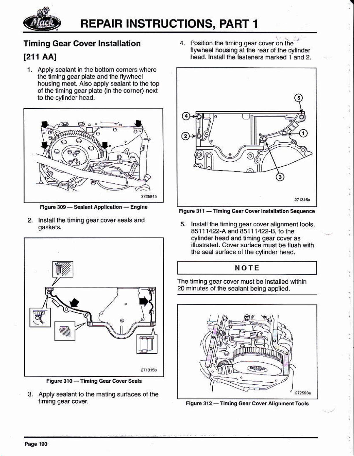
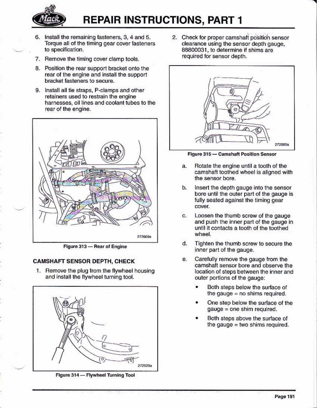
Timing Gear Cover lnslallation
1211
AAI
1 . Apply sealanl in the botlom corneÉ wheÉ
the limirg
houing mééI. Als apply s6ala.l lo lh6 lop
of th6 liming
to thé cylinder héad.
gear plale
geár plale (in
and lhe llywheel
t¡_Le corner) next
4. Posftlon ihe liñi¡g
go¿¡
cowr on
fyvheel housi¡g al the rear ól th6
héad. lnsiall rhé f¿sré¡eE márkéd 1 and 2
I
lhe
q/lindér
2, lnsrall rhe riminq
qeaf
@Er sea s and
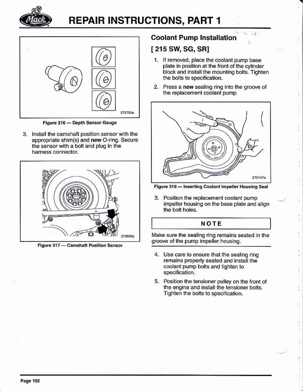
5. lnstall lh€ nming
451 11422 A and 351 1 1422-8, to lhe
cylinder
illusrral€d. CNér suda.e must
lhe seal sulace of lhe cylinder head.
head
qéar
órer
and liming
qed
NOTE
fhe liming
20 mindes
gear
cover must b6 inslalled wilhin
ol lhe sealant bei¡q ápptied.
ignment
a
cover as
be l¡ush with
toolsj
3. Apply sealáñt to the matlng súóces of the
Page 27
BEPAIB INSTRUCTIONS,
PART 1
lnslalllhe fema¡nl¡q faslené6,3, 4 áñd 5.
Toque all ol rhe liming
Rémów lhé liming
Posilion
8.
Éár ófth¿ énginé
lhe @r supporl brackel onto the
gear
cMr lasten6rs
@@r .lamp l@ls.
inlalllhe
and
supporl
brrck l l'srsnáB ió s¡.x¡.
lnstallalltiá sl€p3. P-clampl
9.
¡6lain€B Esd lo r6slrain lh€ €ngin6
harnesses, o¡l l¡nes and c@lanl lubes lo lhe
and olher
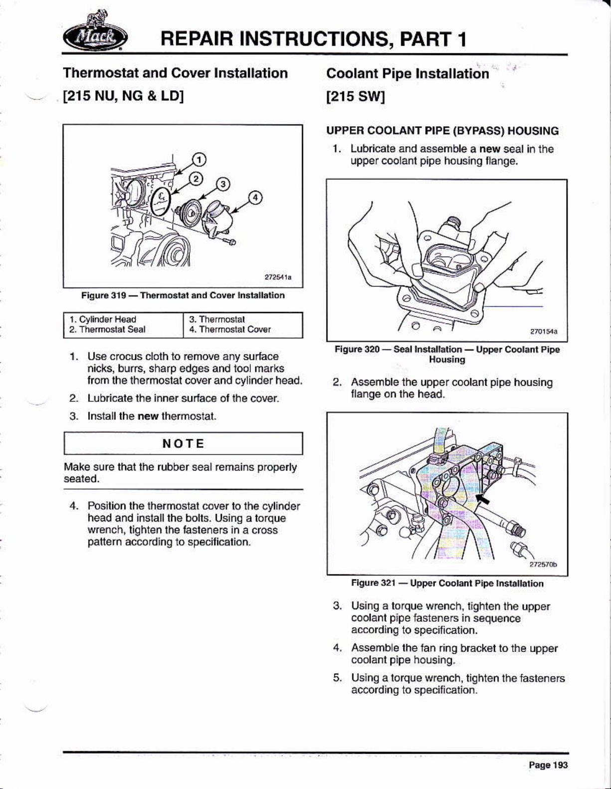
2.
Check tor
cléa€nce
43400031,ló délBñiñe it
required lor ssn$r déplh.
prcper
using lhe senerdeplh
a. Fotát6 lhe éngine
@mshai i@thed wheél is aliqned uilh
enshai
unlil a loolh of lhe
póaito'n
qáuqé,
shims are
sensor
CAMSHAFT SENSOB DEPTH, CHECK
1. Beñ@ lhs
inslall
and
plug
lom lh6llyuheel holsing
lhe fywheel lur¡¡¡q lool.
b, lnse lhe depih
boé unlil ü6 oulér
lully seated aqahsi the nhhq
c. Looeén lhe
and
until il coólacfs a tooih d ln€ loolhod
Tigr'ién rhe thumb
Ca€lulry réño€ lhé
camshaf señsor bor€ and
localion
outer
.
.
.
thó i¡n€rpa oflhégaugéin
Púsh
ot steps belweén ihe inn6r áñd
pódionsol
Bolh
sleps bel@ lhe sula@ of
gauq6
ihe
Oño slsp b¿low
qauge
Borh steps abM lhe
gauqe
lhe
qauqe
lhumb $r4 ol lhe
inlo lhe sensor
pán
ol tre
$f4 io *curc the
gauge
gauge:
rhe
no shims required.
=
lhe su¡la@ ol lhe
oné shim €qunéd.
=
lwo shims equi6d.
=
gauge
gear
gauge
fom the
obsetue lhe
suúce ot
is
(d,---
-5r
Page 28
REPAIB INSTRUCTIONS, PART 1
Coolanl Pump lnstallation
@
@
@
3, l.slall
appópnab shrñ(s) and n4 o¡ng. secufe
lhe sersor with a boll and
lhe camshaft
positlon
plug
señsor wlh lhe
in lhé
215 SW
[
remded,
l. lf
plale
block and install the mounling bolts.
the bolls to speoil¡@t¡on.
SG, SBI
posilion
in
placelhe
al rhe font
c@lánt
ot the cytinde¡
púñp
2. Prcss a ns selinq dhQ inlo lhe
repla.emenl
the
@olanl
pump.
b66
Tighleñ
grodé
ol
3. Posilion lh6 €placémérl coolani
hpellerhousing on the base
plalo
NOfE
¡rake sur6lhé
qbde
of the
sealinq ng reñains seaied h ihe
PUnP
imp6llérhous
nq.
4, lJse caE to éhsúre that ihe seal
@mains
mo ant
5. Poslion lh6 l6nsionér
lhe engine and ¡nsialllhe tension$ bolts.
Tlghlen
pbpeny
pump
lhe bolls lo speciñcation.
sealed and inslállrh6
bolts
and lighle¡ lo
pulley
on lhe f.ont of
pump
and a ion
ng r ng
Page 29
REPAIR
INSTRUCTIONS, PART
1
Thermostat and
[215
NU, NG & LD]
l
Ct,nderH€¿d
Uss cocus cloth 10 r€mow ány su¡lacé
nicks, buft, sharp edges añd lool ñarks
Cover
t
lnstallation
3.Th€,mo,Lar
fom lhe rhermoslal @ver and d/linder head.
Lubn.alé lh€ inner
suda.e ol lhe co@r
Coolant P¡pe lnstallation
[215
UPPEB COOLAI¡II PIPE (BYPASS)
SWI
1 . Lubricato ánd asémble
upper coolanl
p¡pe
housing lláng€.
uppercoolant
a
ñ4
Pipé
HOUSING
seal in the
housing
lnslall lhé néw lhémGral.
3-
NOTE
Make sure lhai the tubber *al remáins
4- Pcilioñ thé lh6moslal cóver lo
head and inslalllhe bolls. Using a lorque
w€nch,liqhien
paliem
acerding lo sp€cilicárión.
lhe lasleneE an a cross
lhe .ylinde¡
proD6
v
FrsuE o1
Using á lo
coolanl
aúoding
Asseñb e lhe lan r¡ng b6ck6l lo the upper
using
ac@rdinq to spéciñcalion
upper cooranr
-
que
wren. h, l¡ghlen thé upper
p¡pe
fa$enere in
lo specinatun.
loque
a
w@nch, liqhten thé lasteneE
p¡pé
hsbÍa
sequence
on
Page 30
REPAIR INSTRUCTIONS, PART 1
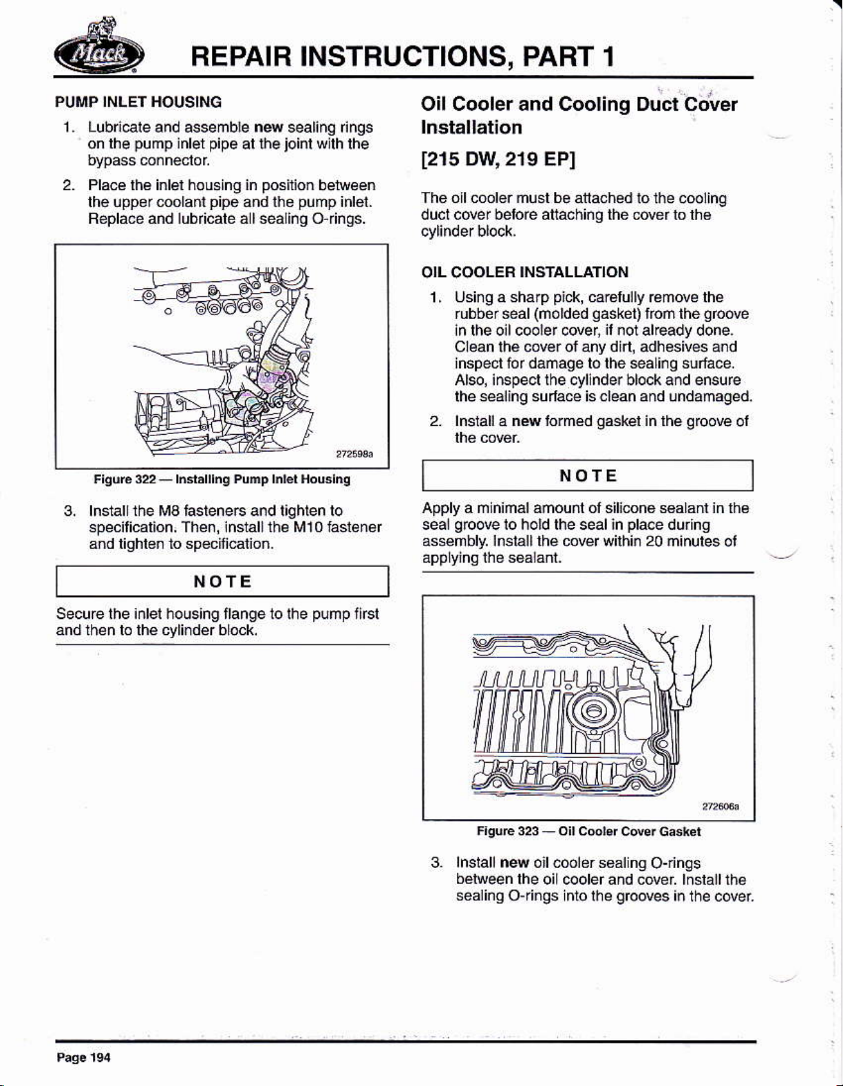
PUMP INLET HOUSING
1 Lubndeand assemble nssealing Íngs
on lhe
pump
inbr
pipe
ar r-he
2. Plae lhá inlel housing in
th6 uppereolantpipo and the
Replacé and lubficale á I sea lno o finos.
joinr
posil¡on
pump
wjlh
belweén
inlei.
rhe
Oil Coolerand Cooling Duct cover
[215
The oll coolor músl be atached
duct cover belo€ aftaohing the Ó@r b lhé
OIL COOLER
Dw' 2r9 EPI
the cooling
1o
INSTALLATION
1
Using a shálp
,
rubber sear
¡n lheoilcooler c@er,
Clean lhe
inspect for danage ló lhe *a inq sulfáce.
Ale, inspecl thecyllnderblocka¡d ensure
lheséaling
2. lnslall a nN lo¡med
pick,
carBlully remde lhe
(norded
cover of ány din, adhesives a¡d
sulae is clean
qasket)
il
notal€ady done.
'fon
and undamagéd.
g*kel
in lhe
the
grcove
g@ove
NOTE
ol
3. lnstall the Ma hsleneG and tiqhlen lo
specilicalión,
3ñd liqhbn to specifiatioñ.
Th€n,
housing trange 10 lhe
inslallrh¿ M10 faslen6r
NOTE
pump
flrsl
Apply a ñ ñimal ámouñt ol slicona saLant in lhs
grcove
sea!
as*nbly.
lo hold rhe seal in
lnslalllhé
mq
3. lnslallnq oil6lers6alng
bé¡reen
sealingojings nto
lhe oi cooler ahd covel lnslallrhe
wilhin
lhe
prace
20
O-nnqs
grooves
durng
minules ot
¡¡ the cover
Page 31

REPAIR
INSTRUCTIONS,
COOLING DUCT COVER ¡NSTALIAT¡ON
PABT 1
1. Feplace lhe Mler
lormed ¡ubber
Lubricále néw
2. Wilh assislance.
assembly h
gasket
gaslel
pláce.
NOTE
pump
sel the c@ling duct cder
inler
hbuslng
wlih a ñew
upo¡ i¡sta laton.
lnslalllhé uppé¡ éí
gsket,
5,
Using a lorque wrench, t¡qhien the tasteñers
iñ sequgncé amoding ro
lnslallrhe
cooler T¡qtfen tóténaB 1o spécilicalion
oi @derll@
speitiellon.
plate
over the oit
This mouñilng lo@l
3. Using lh€ ass€mb
the cover loeard lo cómp€ss lhé lomed
rubbé¡
the upper ¡iahl corner l4lener
gaskel
on is sloted lor¿dtúsrm€nr.
y
lool,
3a300022,
al lhe waler
pump
NOTE
A small
kéep fóm
lool fool is
p¡e.e
ol ñétál srock
deiormlng thé slamped
pressi¡g
aqainsl.
should be used b
cwer that the
push
inbr. hsla I
frsu6
3¿
coo¡ins oud ca$ adjudm¿ ródl
-
Page 32

REPAIR INSTRUCTIONS, PART
1
4. Adiusl 6wr as €qui€d
rówéf énrér lasrénéfs ró
NOTE
The uppér cenler mourninq location h6 á liqht€r
ldeÉñe than olher moúñ1iñ0 locaiions.
5. slart a I reñalnlhg m@r lastene6 ahd
lolqle üg}nen bsleners to speciti€lion,
Oil Filter Housing
[21e
EPI
L hsla I the ea¡
wlh a new
clamps in
cde¡, insla I lhe iasleneG and lighlen lo
gaskei.
posilion
lnstallalion
pipe
lo lhe oil @oler
Place lhé rálaining
on lhe oilmolerducl
cow¡
and
gasket
posil
on lhe rear
to the engi.é btock
pipe.
pipe
ear
lnslalllhe
3.
lnsrall rhe oil li[er housing onro rhé énsina
block
lnslall lhé fásl6nérs to rhe
fller hous¡ng. Toque the bolls to
lnstall the lont
lhéoi
fllerhousngandlheóil@o¡ercovei
p¡pe
wilh n4 seals belleeñ
Torqle lhe
n the olt
2. lnsialllwo allgnñenl
gskél
in
place
ard 10 aid in lhe alignmenl oi
pins
-),
to holdlho
pipes
7. hstáll all hárd
(molaff
and oil) lo lhá
ollcooler@rel Beplace and lubricate all
sealinq
O{in$, Alsq Bpla@ sealing
w6he6forlhe banio finino on lhé oil@oler
covei Tiqhlen banjo lili¡nqs to specifications.
Page 33

REPAIB INSTRUCTIONS,
PART 1
Exhaust
1214
Manifold lnstallat¡on
EGI
NOTE
The éxhaust manilold mounling laslene6
used lire l¡mes u¡less the mánffold ls béino
rcpla@d.lflhe manitold is being éplaced, use
can be
1, Clean lhe manilold mounling suriace on lhe
2. T¿mpoÉrily insláll án alignm6d slud at each
exhaust manfold fanqe bcal¡on on lhe
NOfE
This is don€ lo hold lhé manifold whil¿
the manifold
gaskels
lof ¡nslallal¡on ol lhe bons
posilioning
o
1. Múibrd s ds
4. Apply ánli-séizá.ompou¡d
and under ths h6áds or contacl
áll lhe mánilold laslé¡e6
(ftbl)
NOTE
2. cv ndsr Hd se
l
(wih
to the threads
sula@s ol
o' o
ae\
(_ll
,o
F'Urc3sAl¡gnm¿dPhh3bll¡lio.
3. lnsrall néw
wilhthe s€a
qaskéts
The
aid i¡ ¡nsla lation. Mak€ su@ lo
gaskel
lhe
gEphil¿
libn side
qakets
side
oñlo lhe
lacing
NOTE
ár€ malkéd "MANIFOLD
lMrd lhe exhaúst ñan told. The
gaskel
ol lhe
ój
l¡re
SIDEI 10
this side ol
da@
laces lhe cyllndar
Anli-s€izé hélps
cofosioñ and ¡€duces ficlion
inlended clamp load oñ the compo¡énl whe¡
qhléning
1
rhé
5. lnsiall lhe dhausl mániióld
alignmenl
in lhé low.
p¡nsen
@placed wnh ñounling lásleneF
p@nt
hsleneF to specifi€lion.
plns.
holes, Now lhe upper alignm¿nr
b6 émowd o¡e
iasiener oxidatioñ
lo help ach¡eve the
oEr lhe
l6tállfast€náE wilh
ala lme and
and the
spacers
NOTE
M¿ké surelhe
in themdilold
Exhaúst man lold laslene6
Tiqhlen
6.
lhe l¿s16n6rs lo
sp¡@É ¿r€ seated
siep bore hole
€n bB uséd
speciti€l¡on.
p@pe¡ y
loc¿xon.
up
Page 34

REPAIR INSTBUCTIONS, PART 1
Turbocharger lnslallat¡on
[214
SCI
Lcaurror,
Use oity ¡ev md aryove.t
w aB a¡t. oil 4d dhaust Mnectare ¡a
tuftnchatgú. Avaid the @ of *al¡ng d
Le
jakt
úrpoúds ar a|¡ l¡anged @nñec1¡ore.
fhopuoh
pañ¡des
¡nducled dutkg
te to
ha nd I i n
Aftét únpte¿ns úq¡he ea*ñt)ly, l¡¡l the
tutbocharyet ol
o¡l belote sbn¡N
ptace¿úe
ENG¡NE PBEPABA|ION
1.
tnspecl the i¡1ake ánd exhaust systems
leading to and
máke suG there is no foreign ñálelal
incudi¡g búiÍs and ooe lining fagments.
.lea¡tress ¡s rcqu¡ted. Sna
ñ úúse @vee b¡ü danage
h¡gh-speed opetut¡ü. Bé
plug
the inlal and últel
g
th e tu tuocha
undet Tutbocharyet ¡n ¡he
l@n
ry
paege
lha éNke. Befer ló the
lhe
gaskets
q.
wnh dean
AND
lurbochalgér lo
po¡/l'
at the
il
wh¡|e
eryke
z lnsrallrhe rurbochargertlanqe nurs and
spacers ro rh€ Bxhausr mán lold and
to¡qúe t¡ohien to specilletions.
NOTE
Clean the co¡iact suface oñ the *hausl
manifold,
Relaln the
lu¡bochaqe.
oil €lurn/d@ln back
polectl@
po
€ps @f the
s
lo keep deb'is and dúl
oulollho lurbdharger as
apply añi¡ se¡2e ófrpouñd to lhe théads
and under
the fasleneG. Anli-soiz€ h€lps
hstener ox dalio. @clon and redues
l clon ro help
load on the componont when lighlening
'aslene6
5,
lnstaf nee h
betweén
6,
Pósilion lhe lubocharqer and
aqainsl rh€ Bxhausr manilold.
lhe heads
achiwe lhe
to spec¡iielioñ.
gh
the tulbo fange and
or conl,aol sula@s ot
tempé¡á1uÉ
p pé
gngine
pt€wnl
¡ntended
gaskets
qhausl
gaskels
and
clamp
lhé
y
app
undér lhé conlá.i surláés ol lhe laslénérs
a¡i¡-se¡ze compound tó lhe théáds ánd
Page 35

REPAIR
INSTRUCTIONS, PART 1
a. lnstall the lúrb@hárg¿r oil
9.
(lower)
lnsral
gasket.
with a nN
the oil suppt
Totque-lighlen tho bolts lo
oaskel.
line (uppe4
E¡rrn
pipe
wilh a new
Exhaust Pressure covernortEPG)
lnstallation
gD
234
1. Lower lhe EPG housinq inlo
bétuéen
lhe exhaus!
p¡pe
2. lnsrall a nM hiqhreñpehtué
ho usin
g
and éxhausl
pipe.
posirion
and lurbocharqár
o6két
EPc
/AcauÍtoN
Pra-lill Ihé tutbodÉger w¡lh
S¡añlhg the eñgiñe wiktut oil
Ary" lubaúaget @ dmage lhe luúo.
cl@n úgjre oi¡.
pressure
and
a
3. Tighton lhe clamp
pipe
lo EPG housina.
atiaching lhe dhausi
Page 36

REPAIR INSTRUCTIONS,
PART
1
4. lnslalllhe dhausl clamp lom
EPGrorubocharger
lhe
Siarter lnslallation
1272
The staner is held ln
Nér sruds ireérléd in the bró.k rr á sr'd ii
DHI
plács
by nuls
1 . Using a loque wrcnch,
siuds a@ordhg lo spéciñcalion.
lighten repla@ñóñt
assembled
2. Asseñble lh€ süner on the sruds
in lhe
5. Con¡eclthea¡r súpoly li¡e to lhé EPG.
F.goÉ343_shghbra¡on
3. Using a torqu€ wEnch,
ac@d¡nq to spejlicarion.
lghten the nLns
Page 37

REPAIR
Air Compressor lñstallation
1261
CKI
INSTRUCTIONS, PAFT
2,
Asemble lhe alr coñprá;ior
moonring llange
ollhetimi¡q
1
on ine
géar plate.
1- lnsiall a nNseal inlhe
housinq hou¡lihg fl
ange.
alrcompEssor
3.
Using a lorque wrench, iighleh ihe atlaching
¡úls iñ two slages
aeodlnq lo specitlcatlóó.
Page 38

REPAIR
INSTRUCTIONS, PART
d
1
lnsláll1he cmlanl linás lo lhe
5.
lnslall the lubication tiñes to the an
Tandem Pump
(Fuel
and Power
Steering) lnstallat¡on
[231
AA,262 EBI
1-,nsiall
landeñ
a na OÍng in the
pump
mounlinq llange.
2- Assmble lh€ tándem
pump
ai
qrcove
on
lhe lttaheet
on the
LL)
F¡surc 7-r.nd.ñ
3, Using a b¡que wrcnch,
hsteneB accordinq tosp€cilicalion,
Punp
(Fuer
tighten the attachiñg
'nd
pú.r
srs nq)
Page 39

REPAIR
lnlet Manifold lnstallation
INSTBUCTIONS,
PAHT 1
[214
HD]
1. Usinq a 6haD
rubb€r sai (nolded
¡n the lntaké nañilóld, il nol alréady done.
Clean lhe úanifold ol arry din, adhésivos
and inspeci lor aw damaqe io the séarñq
su¡lace Also, nspecl lhe cylinder head and
ensu¡e
the
2. lnslall a ns rubbor s6ál
lnto the
gl@e
plck,
carelullv renove ths
qaske0
8€alinq sudace
ol lhe iffake man¡hld.
is
(mold€d
lrom the
clean and
s6k€t)
groove
NOTE
Apply a m i¡ imal amo unr ot sil¡cone seala nt in rhe
growe
s@l
a$eúbly. lnslalllhé ñáñilód wilhln 20 ñl¡utes
lo hold
lhe seal
nplacedu ng
Torqle-righren
s6q u€ nce lo sp ecifi@lio..
the
iniake
manilold bolts in
SeuBlhé 6noiné hamésslolhe inlake
ná¡ihld usi.g
l¡siáll rhé
ai l€mp€Elur6 sn.or localed
the inlake and *curelhe hahé* wlh li6
pdiously
eLeclrical con¡ecto. to the charge
r€mowd
on the lop oi
Posirio¡
3.
pGviou!¡y
molnt¡ng bolis with mounring
hold ihe man lold
alig nm€ rn
ma¡¡hld bolts wilh spáÉB.
the intake nanifotd onlo lhé lwo
imlalled
pins
aligrmenl
placé,
in
and install the ¡ema¡n¡no
NOfE
use f4 scf6m wllh mounling
¡nslall¡rg lhe ¡¡lake mañilold.
piós.
siarl hro
space6lo
ihen r6move lhe
spacefs when
(Bocr)
7
Using á torquo wench,
a€oding
io spec licaton.
sen$'
I
qhlen
the sensor
Page 40

REPAIR INSTRUCTIONS,
Englne Prehealer/Spacer
lnstallation
PART 1
[214
HL]
1. Cléán
intak€ ñdilold, ai
lhé lomd $aling sudae on
preheargr
or spac€r, and
2. Posilion lh6 inlál adepr€r and inlér áir
p¡ehearer
n4
$an $e bolls lo hold lh€ Gsémbly
using a 1o¡qué wreñch, tighten lhó lástgnéB
ió
a crcss
lnsrall rhe lan ñnq suppon bEcket mounr¡ng
fásl6ñ6r Torqu€-tqhl6n lhé boh ló
(rf
equ¡pped), of spacer brock w¡rh
gaskers
onro rhe inrake ñanilold, Nexl,
Figu65_l¡l3lAd¡pl€l
patlern
a@ordlng lo specitldlion.
rhé
lo lhé
EECU
t230
EKI
añd Cooler
lnstallation
NOfE
The sóquénc6 iñwhich lhá luél iinér
housing, luel lines and EECUar6asmbled
lhe engine depends on the
uséd. For €nginé slánds rhar
atáched lo th€ l€lt sid6 ol lhe
.omponenis cannol be ¡¡sialled unt¡laltd lhé
6ngiñé hás béé. Émw€d lrcm
Fuél lEsh lróm
EECU. Th6 mol6r
the luel lrcm the lank inló lhs lu6lpump.
the tank serves as @otant tor lh€
@nnets into lhe line cary¡nq
Vpe
use an adaplef
engine, lhese
ELve
ol enqhe sland
lhe fepa¡f sláñd.
on
plate
f equapped,
p€hearer
10 ths mounring surla@
man¡bld. conne.t and seué the
ground
and
postt
on añd iñstátt thé intél air
relay
bE ker
cables é marked al
(wlrh
on lhe
élay atrached)
inlake
pMér
NOTE
l¡ake sure the @olinq
1. PGilionlhe
insiall ihe ñóunling la6te¡e6.
plar€
EECU on the engine btok and
and EECU mat¡ng
Page 41

REPAIR
NOfE
INSTRUCTIONS,
4.
Uslng alorque sr6nch,lighteñ1hé
in séquence
PART 1
hstenere
adordinq to spéciÍcation.
i¡áke suÉ lhal rubber isolatoE
¡nsialled and thal lh€
Usi.q a
adording to specil ca1 on.
Assemblé lhe coo 6ron lh€ EECU. When
loque wrench,
pcilioning
snalgmund sl@p
unil s
properly
grcund
lhe module, ñake sureihallhe
al lhe uppef r¡stf oi ihe
secured ánd
áre corectty
sl@p is
riqhlen rhe fasieners
prcssád
gounded
in
10
Fuel L¡nes añd Filter
Housing
lnstallation
NOTE
Thesequencéinwhichthéluélf ltérhous¡¡q,
lines and EECU
depends on lh€
engine slands that lse án adápler
lo lhe láft side ol
cannol bé inst¿l sd uff I altér lhe
been removed lom lhe ¡epair sland.
areassembled on lhe enqiné
ol
Vpé
lhe engine,lhese componéñ1s
engine siand ced. For
plalé
ana.hed
engine has
tuet
NOfE
FisuEs
1,
Asemble lh€ tuél finer
2,
Using á lorquo w€nch.
Fü.r Firsf ¿nd HoG¡nq asñbt
acmding lo speciliEi on.
3. Allach
al lhe réaf
p¡pe
lhe
bellveen
a¡d the lilte.hous ng.
housing onlh6 btock.
t¡ghten the taslénerc
the s¡de ot the h€ád
Page 42

REPAIR INSTRUCTIONS, PART
1
Atach the
lnslalllhé iuél rélum liné
cyliñder h*d at lh€ lorn and lh€ lifter válw
lnsrallrhe line ro rhe b¡ock w¡rh P-clamps.
lnsrall lhe lue I relu
line
lo the bl@k with a
line
rn
be¡réen
con¡ect lng the
P-clamp,
rhe
liller Etue housing lo thé EECU ód¿i
lnsrall lh6 lu€l supply and ré1un I nes
belween lhe lue¡
L
U3ing
llttlnqs accordino to specif calio¡.
aloque wE¡6h,lighlen
pump
and thelillér
lhe bahlo
Lop.P,eure Fler
5.
súpp¡y
Pump
Crankcase Ventilation
1.
Clean lhe cankÉse venlilallon sepaáto¡
malinq sulacé o. lhe éngine
n4 rubber
aáskel
iffo {ré s6pa6ror
(Mounr€d
ro Poref
Separator
btock. lnstalt a
2. Assemble the sepaábr on lhe blóck
and
Page 43

BEPAIB INSTRUCTIONS,
PART
1
3. l.rsing a ioque w€nch, l¡ghlen lhe lasleneB
ac6rdi¡g
4. Assemble
ou el conneclor a¡d instal hose clámps.
lo
specif calion
lhe ouíel hose on lhe separalor
5. ljslng a torque wrench, liqhlBn the hc6
clamp
6. Assmblé 1¡e lnler hce
inlel and
in a iulu@ slep, lnsiattho* ctamps.
7.
Using a lorque wench, tlghlen the h66
clamp tasl€nerc ác@.ding
laslenerc
pr€pa€
ac@rding !o sp4¡l¡*¡on.
on the separator
fo¡ € re cov6r
connslion
lo sp4iti€lion.
1. Assémblé the
ánd I¿¡
.Enkshafl vibration'damper
puloyon
rhe
cÉñlshail hub Ging
NOTE
F¡duress.FanDvePu'le'.ndc
virüaion o¿npér
t2
c,¡nrshaft Hub
t3
Crankshaft Vibration Damper and
Fan
Pulley lnslallatlon
[212
RB,2'16'tA]
AcaurroN
When
to dañage llÉ fo6kg. Denls
hús¡ng
v¡b@üú
h*d ¡h¡s autim nay
lnspecllhe vibElion
llu d leaks in lhe outer housing. ll any
widénr, rhe
clos€ cloaEnce
¡nd lhe rolorinsids, denrs ór nrcks
conlact belween lhe two componenls.
will dele o¡ate lhe dampeñi¡q eftucl oJ rhé
handling a tbnton darpéL bé a6tul
ln the au¡er
s¡l¡ rcndq the danpet
danpe. @nnol be Epated. Failure to
re'u|t in see engine
damper lof dents, n¡cks or
dampermustbe reptac6d. Duelolhe
beñveen lhe damper housing
inefecfive. rhe
oi l¡ese are
nayeuse
Fluid loss
na¡
Using aloquewcnch,tghlenlhe
l6léneF in
a@odhg to sp6cilicalion.
3.
Asseñb e lh€ fonl
(FEPTO)
last6néc in
a@ordina ro
sequence in two stéps
engine
il equ¡pped. Tighrén rhe
sequencé in ldo sleps
spe.ilication.
p@er
ataching
láke of
atachlng
Page 44

BEPAIR INSTBUCTIONS, PART
A*emble
6.
compGssoron lhei
the allernalor and reriqeÉ;l
1
pads.
F¡qure 3@
-
FDnt
E
Po@ Tar.¡r
qiru
Alternator and Ref r¡gerant
Compressor
1271
C8,264
Assemble lhé allémalo. mouñrinq brackel
onlo lho cylind6r block. Ighlon ih6
Iastere6 a.cordang to spe¡licalion.
2,
ll ¡emoved and nol
á$émbl6lhé lronl énginé supporl mounling
báckel on lhe cy inder block. This brackel
pr@ldes
also
Using á lorque wBnch,lighlén
lor the b€ckei ánd ñou áccording lo
lf €mN¿d,
Using a lorqúe wrench,
ácordino to specf cár on.
lnstallation
DP1
ppiolsly
lhe mounlinq
assemb e the bett tensioñ idter
lighlen lhe lalene6
installed,
poinls
lhé
(FEProl
io¡ lhe
lasleneB
s. m 6mp,ésor
I
6. Mounr¡m Bccb| Fron'
|
Enané súppod
I
usinq alorque wrench, l¡ghlenlhelasleñefs
a€oding lo specmcatun.
ll a hárnBss is installéd. secuely
the eLectlical wi nqáslagg€ddu ng
L
Assemble lhe be I
and
compressor hubs, r reñóved.
pulleys
on lh€ állénaror
connect
Page 45

REPAIB INSTRUCTIONS,
Wiring Harness lnstallat¡on
wñqHafÉss
l3
PABT 1
1. Roule añd
engine s noled durlng di6a6sembly,
2. lnsén lhé unil injéclor
throqgh the holé l¡ the tlñlnq
pGition
the harnéss on fie
ponion
ol lhe h.me$
gear
housi¡g.
3. Connecl ihe hamess lo each iñiectóf.
4, Conneclthehamessiotheengiñébáké
mnlrcl valve t
Usinq hioh-lémpéÉlue wne
aliach ihe harness lo lhe cyLinder head.
previously
¡t nol
6.
wiring harness
valve. secure the hafn€ss lo lhé cónrfol
Blve as shown iñ Figué 363. i¡ák€ suro
thal lhé ham€s is
the boss al the lóp of the Elw assémbly.
lnslalléd.
Íes. 983472,
done, caelul
@er lhe engine brake control
pGilioned
y
ror,lo lhe
lo the s¡de of
/AcaurroN
Do Nof mute
lop oÍ the engine tuake
enough deatatu belween the valve
wive
@ver far lhe hatñess when rhe
insblled. fhe hatress
s¡de af the b6s ro awid da@ge
the hames o@¡ the bos at rhe
@nlrcl hlve. Therc ¡s nat
añd the
@ver
ñusl be
pós¡ioned
¡o the hahess.
is
¡ó lhe
2. cúLrclva €
|
ahe énernal
encGed in a@fdion lubinq. Th€rá afa séváEl
unils éách of which
permn
thai
allachmerl
CONNECTING THE EECU
L Ch€ck l¡\é lénsio.
p¡ns
podon
.o¡veniont st
lo the block in úrious localions.
úshq ihe tésl
ol lhe w
¡s tilled w¡lh end connecto6
ol lhe lermanal ¿on n6cto I
pins
ng hame6s is
jóininq
ging
n
¡
roól
kit 999000a.
a¡d
NOfE
ll
lerminal
2.
pins
are damaged
or coroded, ¡ep ace
Caelullyengagetheuppera¡dlowerwiring
haiñess connécroF
lhe connecloG are lalched
lo lhe EEcu. v€rify lhai
propedy
and
Ue aE to
aE sla¡qft an.l undanaged,
^caurroN
entute ¡hat the EECU teminat
pks
Page 46

REPAIR INSTRUCTIONS, PABT 1
3. lnslall lhe bolls
lo
secufe
lh6 wiing hafness
Cylinder Head
(Valve)
Cover
lnslallation
[211
JBI
1.
ean lhé
C
cylhder héad. The su¡la@s shóuld bó cléár
of a¡y di¡l or debrls and l¡ee ol any oil.
2. lnspecl lhe
@pla€mént
ñe
lhat I ¡s
@nrour
g6két
gaskel
is necéssary caEtully
gdk6t
intó the channel, ñákiño sué
propeny
of rhé chanñé|.
sáaling
lof damage. li
sllace ol lhe
*aled and tollds lhe
r
plácá
a
Cónnecl thé vanous le¡mináls as lagged al
di*ssembly lo áll ssnso6, rslays áñd
componenls such as ihe stailef, allernalof
and Élli96€nl cómprcssrámong olhé6.
Anach rh€ clamps lo hold lhe hamess
5.
on lhe
FlguEscyn.&fH*dcov¿lG'3k¿t
3. Appry a 2 mm
i0.079
séalanliolh¿ areawhere lhe liming @ver
ándlhecylinderhoad mééi. This
is on bolh s¡des of the cyli¡der héád.
Ca€lully
cylindsr h6ad and make
rema¡ns
posilion
pope y
¡nch) bead of MAoK
valve
lhe
séátéd.
cover on the
lhal
su€
paning
liné
lhe seal
Page 47

REPAIR
INSTRUCTIONS,
PART 1
4. lñstálllhé sp ngloaded
covei Tofqúe tlqhloñ lha
sequen@
io speoilication.
bolts ¡n lhe utve
@l€ cover bolts in
NOTE
The cyl¡nder head cdór musl b€
wilhin 20 mi¡utes ol lhe séálánl beinq
inlake
pov¡de
manitold. Torquerlghlen
e@n te¡sion on lhé
The boll springs
lnsla¡llh€ last€néB securino lhe
5.
venl¡bnon tube and bÉcket lo the vd@
cover and
lh€ fásl€néc lo specilicalion.
in$aned
c@nkcse
NOTE
l¡spetthecEnkcase ventllatión lubóOjing and
Fan Hub
[216
and Drive Beli lnstállation
AAI
1. Pla@ lhe iáñ hub bráckét
pos
lion
al lhe f@nl of ihe cylind$ héad
block. lnslalllhé
lighleó 10 sp4jfi calion.
mounting tasleneG and
a$embly ¡n
and
t1&€soryod€Bd
Puñe Bor'
I
Pláce lhe 1áñ
lens¡oneriñ
housing.
ll nor ¿keády
drire bsll i€nsioner
cylindef block. lnsralllhe l4te¡e6
Check lhe @nd¡llóñ of borh of rhé óridi¡sr
A/c/áltemalor
Check tor dry
@Place wilh nd b€lls I ány
P€rlhe
¡Llo/alterñalo¡ and lan/water
d ve and
posirion
lnslatt lh6 tasleners
done,
a¡d waier
cEcks or scuf marks ánd
ac@$ory rouling d8cal, bure
puñp
on lhe coohfn
pt¿c6 rhe
pGrlonon
m
pumpÍan
rssiomf
driw beh
pump
and l¡qhten ló
a@essory
th6
and
belrs.
ol these
lhe
pump
betts.
Page 48

REPAIR INSTRUCTIONS, PART 1
7. Using lool
/14392,
J
eay fom ihe ran and wátér
and insralllhe belt. Reléass lh€ lénsion
pry
lhe be¡l lens¡oner
pump
dnw beh
Removing Engine ftom Eng¡ne
Sland
and
6. Place a 1/2-¡nch Elchel or speclal lool
J4€92inlhéa@essoryd
nolch. lñs1álllh6 dfive belt by
lenslonef away fom lhe bell lo €li4e lhe
lénsion on lhé adiúste! ánd állow thé bélt lo
srip ó¡io ihe ¡l/c @npfes$r
Feleaé the léñsion and r¿move lhe tod .
vebelllánsionér
pryiñ0lhe
purréy.
t200
fhe
ñwr he exnise.l whíle
the stan !. Faitut¿ to u*
aDd ,allure to keep
in e¡iffi
EBI
qglre
ls very heaw an.¡ at@e úuüú
¡t is belng úfted lrcn
p*@I
pñpü
yoú
bo.,y ct@t ñay re tt
¡n¡ury
éqlipúent
ot.l@th ÍtE
úgíre shoúLt la d s¡r.rdúly ah¡ft
1. Atach
J 47033-6 and
a. S idé lhé
b Placelhe
c. Sl¡de thé réár lifting
d,
engine lifung ioo s J 47033-1,
4703a4
J
centerengine liftiñq barder
thé cylind€r head
cl4is
clévis lo
ey€s ánd s*ure
pin.
Connect thé c€nlé¡ lifiing
lhe chain on lhe hoisl.
l¡fing cha¡n toihe é¡giná tift
lifting bar and iñslalllh6
goll
on lhe floñt sectioñ ol lh€ 6ng ne
lifting bBckel
installth6
lo lhe cyl¡nde¡ héád áñd
pin
in
as lottows:
cwerard instal lhe
lhe chain lo th6
plare
inlo
pin.
lhe bai
out of
bar
the @nter
é. Torqué'lighlen litt ng
bracket hslene6
Page 49

REPAIB INSTRUCTIONS,
PART 1
U* on¡y the ch¿¡ns, ctév¡B dnd tiking
prov¡ded
úé ¡hé @ret
¿Iów lhé úg¡re to fa,
pet@nal
3.
wilh th* spec¡al tals. Fail* Io
sp@lal too¡ @nponents náy
@u.¡ng 4 @5
ln¡úry ú rlééth.
Supportlheweighl of th6 én9in6 usinq a
mobile ll@rcEnesuch as OfC 16.1313 or
equivalentcrane capable ot lifing lhe
€ngi¡é. Posilion th6 cEné and hook up ló
the bar as d6e as
slighrly ro apply rension rolhe chain.
With
€ngi¡e
fasleneBlrom the enq¡ne stánd.
Using theenlhe hoisl,
suitable supporr Éck or insiall rhe engine i¡
lhe @hicle
REPATR TNSTFUCIIONS,
the
w€ight,
lifting
(sée
pos
ble. Baiso lhe cnno
device now suppo ing rhe
@mov€
F¿o,h€ /rs¿tlrli¿, in lhe
the mou¡ling
pla@
lhe engine in a
PART 1 secrion).
pla¿e
1. r nól ak€ady don
oompo¡enls onlh6 éngine
p
ocedu fes cove red ea i6r in this
.
Enginewkins harné*
I
cfa¡kcase ventilát on lubing
.
EEC|Jandcoolinqplal6
Fuel l¡lter valve hóusing and luéllines
Cra.kcase venlilalion sepa€lor
e, asser; blé thd lottowjns
using lhe
6eclion.
F¡lters and Miscellaneous
Components
[219
This seclion coveG lnslallation ol lill6B ánd olhér
componenls thar might
a$embly opéaiions and to which nólhing is
EV,2t5 LDI
lnstallation
gel
in
lhe way 01 olher
NOfE
Ths sequ6nc¿ in which
housing, tuell¡nesá.d EECU ဠssembled
lh6 ¿nq né dépendsoñ
u@d. Fof engin€ slands thal
attached lo lhe len s¡dé of lh6 ánginé, rhese
cóñpoñ6¡ls cannol
engine h6 b$n fomoved t@m
the luell¡ller hl@
the lype ól6nQiné sland
use an adapler
be ¡nslalled uñti aft€flhe
lhe repa¡¡ siand.
on
p
até
i . Eno n6 w?iñq
Hamess
I
I
I
2. Assem ble thé fu ll-llów
lo
.onlacl
Assemblelhe
3.
contácr
assémble
contáó1Plus 3/4 lo 1
plus
3L/4lo I lurn.
Plus
bypasso nleránd
3/4 lo 1 lurñ.
lhe coolanl flteránd tghren 10
4. EECU
6.Cankasvéñúárón
s+¿mbr
oil tilte 6 and tig ht€n
Ughtenlo
lurn.
Page 50

REPAIR INSTRUCTIONS, PART 1
ENGINE INSTALLATION
Special Tools
General lnstructions
Détails
lfom one Éhicle to snolier This setioñ
gene@l guidelin6
oi
rhé
enqine
insla
Jor insralling an MPB enqine in
lalion
p.océdue
prdidos
NOTE
Belore insiafing lhe enqin6, mak8 su€
equipme¡t a@ inspecred lor sfety and
1. Positlon the vehiclo 0n a fat, lwel 6u.lace
Apply lhe
wheels.Obse@allsatelypreautións.
parklng
brako añd block ihe
Ery
NOfE
R6rer to th€ SPECIFICATIONS
lnirfrá¡oñ ¿boll lhe laslénéB mé.lioned
Some
sp€cilc sequence,
speciñed i¡ the lorquo sp€cili@tion
groups
ot
Paflens ol sequence are also
'aslene6
lnsrallation
Thé engine ¡3 obv¡ously
handle. Obta¡n a helper
l¡ftlng devlce to support il salély during
iBrállátion-
esú ir séveÉ
FailüE to hedthis r¿rniñg ñáy
p€bonal
and
section lor
musl be tlqhtened in a
seclion,
heavy and difñcult lo
prd¡de
a súitable
¡njury
be ou
Page 51

REPAIR INSTRUCTIONS,
PART 1
wh¡lé i.sratl¡ng
lhal ñay ktañée. such ae eng¡ne
@rnpúeñl' bhcke.ls, clanps and other
a¡tached to the lqñe and @b. Fá¡lurc to heetl
¡h¡B 6úim n6y
ghe
aúl other
1
Cryérlhé
^caurroN
the engke, wat h lot abstucl¡ús
and chassÉ
pañs
Esult
in
sevee danage to ¡he
@pú4ts.
valvé méchanism and
géarlÉin
wlh a suitable clolh or simlaf covedng 10
p@enl
3,
Aiach the €ngina lifting tool, J 47034, lo ñe
e ñOine. Secure lhe enq lne llftlng tool to lhe
ircnl ol rhe cylinder head and ro lhe rear al
di¡l and debris lom enleing lhe
thelywh6el housinq. Adlusllhá1oo to
hsral lhe
w¡ench, 1
screws ácerding 10
Wlhdaw lh6 lEnsmission
12.
a. lf hañual lE nsm iss
rEnsmr$ron ahd, u]eind a
ghlen
the l€nsmissiú áltaching
specilicalion,
io n. atlach lhe
. uich linkage añd bfacker Gia¡ñing
b, lf aulomatic
tofque conrener accéss
Aflach the h@d esl crossmember ll
Co¡nect slartBr wnes and cables,
15.
Attach thé
AIlach lhe exhausl syslem braókels.
17.
Aliach lhe exhaust syslém lo lhe
peérsiée
fansmission, attach ihe
ng hoses
jack.
pan€l
lorque
and
and
Ensurc aI bofts a'.t
posl
the eng¡ne stú.1, Fallwe to
bóIts ¿nd
rcsult ¡n
one.r
píre
petsorat
priot
to rñoúng thé úg¡re hoñ
ól lhé éng¡n. lifting tool en
ínjury .ltor dédh.
4. Usinq lhé €ngine iiftinglool,
wlih lhe ald of the helper, lifi and lower lhé
Alig n lhé áng i¡e wilh
5.
lnslalland, using a
lhe rear engine suppon aftaching screws
amo dinq
lnslall and,
lhe lóñt enqin6 suppó
a@ofding 10 specllication
Femo@lhe
L App
y
án évén 2
s€lantátlhe
cyli¡der head a¡d tholiming óEr,
pe.ll¡catlo
1o s
u6¡ng a loque we¡ch, lighlen
engine litl¡.o lool lrcm lhé
joinr
arc @récüy
üns
propúly
47034,
J
lhe I ransm¡sslo n.
toque wEnch, tiqhten
n.
aiaching scr4
(t64
mm
lines
inch) bead ot
between the
lnaan an
and
The rád¡álor and CAC ásseFbly
ls hdy and
d¡fi¡culllo handle, Prcvidé á su¡tablé lifiing
dev¡e á¡d á hélpér
lnslallation, Failuré to héed this
Esult
19.
To all@ Jór chssis
appllcatlohs, tho lan
ilush
qap
belween the fonl lacé ot
lhé back lacé óf lhé rán sh.ó'
in
severc
Anach
agai¡st1he shroud on cU modetchass¡s.
of 15-20 mm (0.59
ihe adialor and CAC 6sembly.
lo supporlltsalelydur¡ng
waming may
Dersonal
N OTE
anlculatlon in s6ver6 service
¡n¡ury.
ing rubbefsea doés notlil
4.79 iñch) disls
the aluminuñ tan nng b
'd
A
NOTE
¡stalllhe va@ 6v€r wilhin 20 minules oi
10. lnslá lrhé varvé cóvér
Page 52

BEPAIB INSTBUCTIONS,
PART 1
21- Co.necl üE
fan
aclualor
22. Connecl lhe engine c@lanl lemp€@luré
23. All5ch the chafge air @oler oullel
24. Atach the charge
air
cmlér
inlél
25. Aia.h thé dolant dpanslon lank.
29. IttheBhicLs is €qu¡pped wlh;ú "
@nd¡lio¡¡.9:
a. Conñ€ct lh€ ¡/C comprGso¡
r
di$harge
h conner rhe ¡Jc ln6 al tho
c.
Connel
d. coñn6ct ih6low
lhe
p@ssu@
présuÉ
s¡l6h on lhe
cutour
e, Recharqe lhe NC syreñ wnh
réfigéErn
usiñg cl
dd recycling equipñenl for R134A.
30. lnstall lhe ¡nlei a¡r system componénls
31. Connecl lhe ¡nlel a.r healer ¡,
32. Atach lhe oil and tuel t¡lle6 and lhe coolanl
Closé all dhins ánd dain Elwa
33.
04. Connect all so¡so6 a¡d acluatoB,
gérant
p€senl.
rccd6ry
26. Anach ihs l@sr Édiálor lube.
27. Conn4l the eb h@ler and luel heáer
c@lanl
€rurn lines ¡o rhá ld6r Ediaror
24. atlach ihé úpper radlalor lubé.
Add oil and molant. lf
36-
qtEclor¡njeclorwhen
aEilable, use @dal
add¡nq óolánt.
37. Atiach the h@d, or Épla@ lhá lih€d
cab.
Page 53

REPAIR INSTRUCTIONS, PART 2
Page 54

REPAIR INSTRUCTIONS, PART 2
rN-cHASSTS
PART/COMPONENT
PROCEDURES
This séclion
opeálions wh¡ch €n bé doñé in chasis withóú
a comprere enqlne @fhau¡. The* ope€rions
.
CAMSHAFÍgEAFINGBFACKETS,
BEPLACEMENT
.
OIL fHEBMOSTAT ANO
SAFETY VALVE
.
CFANKSHAFT
!
CRANKSHAFT
.
CBANKCASE VENIIIAfION
SEPAFATOF
.
OIL
.
INJECTORCOPPERSLEEVE
pÉsenls
PUMP REPLACE¡'ENT
slandalone rcplacemenl
PFESSURE
BEPLACE¡¡ENÍ
FBOÑT
BEARSEA!
REPLACEI¡ ENT
SEAL
{CCV)
CAMSHAFT BEARING
BRACKETS, REPLACEMENT
(MACK
[2r3
This inlorñátióñ cdé6
€placing iaclory or aferñárkél camshalr báárino
bEckets
Preliminary Steps
fh. lóllówing eñFótunts m¿d lo b.
retuved ¡ú a@ss to the @ñ.haft bñing
CompEsion BEke Solenoid Valve
'
t
Camshaft Assembly
MP8 ENGINE)
CJ]
(lMr
jourñals)
guidélinés
on ihe MAoK MPB
wheñ
.
UNIfINJECfOFCLEANING
.
VALVÉ STEM HEIGHT MEASUFEMENT
.
VALVE STEM SEAL REPLACEMENT
Du€lólháEngine Eléctronic
sell lear¡iñg capability, il is nsBssary lo €s€l
learned EECU
€nainé{élá16d componénis, This állNslhe
EECU lo leañ lhe new conponsnts béhávior
After sedl.inq is comp ele,
pa€melers
Codról Uni
atlerseruic¡ng some
pefom
(EECo)
lhe 'Leamed
General lntormallon
Cams hatl bearinq
wilh malchina uppér
nole and mark the 6resp¡ndino
numbeF and insralllhem i¡ rhe cofecr *quén6
wirh marchéd uppérand lwer
jou
rnals are nuñbered 1 7,
lower
and
halves. Ae sure 10
iournal
halves,
Page 55

REPAIB
INSTRUCTIONS, PART 2
Camshaft lnsp€ction
F¡gUl¿3ñfubñB¿'ngBrcchlL¡krHátr
WHEN BEPLACING FACTOBYINSIALLED
JOUFNALS
.
rt a camshaf
túlx á r€plácaménl báaring bEckél wirh rh6
o rig lnal laclory-inslalred bearinO brack€rs.
This is
were alion bored whe¡ lhé 6ñ0iné wás
manutacluEd. A lsden bEckels must be
bsause lhe o¡iqinal bearing b€ckels
jourñar
has se¡zed, Do NoT
To arcid
lhoroogh iñsp€clio¡
feinsralling áner fépracing lhe
u¡neoe$ary derhaúti.o, co¡duct
ol lhe camshait b€for€
beafing báckei
Brackel Replacement Procedure
L Bemow lh€ lower
pry
bar The rearnosl Nó 7 b€ckál €n bé
Bnded
tapping sid€ lo sidé.
should come oll the cyl¡nder héád with lhó
bEc*érs. lr ¡or, remove
by usinq a soft-hced manet and
bea¡inq b€.kets us¡ng a
Crhealignmenl
pins.)
the
pins
a
.
Wheñ réptácing a cylindér héád.
¡4 bearing b6ckelswith original b€ánng
bEckers |lom
onlv new beá n0 bÉckéls on a néw cvlinder
WHEN REPLACING¡NSTALLING
AFTERMARXEfJOURNALS
.
ll the@ are aleady repla@nént b€arlng
bEcksl assmblies
or ñore ass€mblies áre
4senblies nusl be eplaced. Raplac€ménr
backét assmblies
dal-shaped aliqnm6ff
.
For replacement báck6l assmblies
lo€lions 2lhrough
holes ar6 oval-shaped
adjushenl. For bdckéls used in
and 7,
for l@nr-lo{ear
hole is ound wirh an á ignmenl
lüárk thé boaring caps lo lndi€le
allermaiket beáing back6t
ássémblies haE béén in$ánéd
onealiqnméntpin hol6 is
lhe old cytinder head. Use
on the eng¡né, a¡d on€
damaged¡ all s*n
can be ¡defillied by lh6
pin
holes,
6, both alignm6rf
iof sideles¡de
oval-shaped
adjushert ihe se6nd
pln
and cap
nol mix
do
usd ln
pin
lo@lions 1
piñ
lhal
2.
Clean lhe conlact sulacés of rhe
hóád and lhe
3. Usinq
mark thé ñ4 beanng
wilh
a meiatstamp or e édric éiching
lhe nuñb6rs, 1
loclion
Do not e dces¡@
l@e¡ béa ng bráckets.
b€ckeis and caps
th@ugh 7, ¡¡dlcaliñg the
¿r whch eách ¿ssémblywilrbe
^caurtoN
lc@ la
asñü$ whú ñatk¡ng rheit
ctündet had. Dañage
lo úrponenE
pnch
p6il¡an
oylinder
tool,
lhe ba.ker
on the
ca, resu¡¡.
Page 56

REPAIB INSTBUCTIONS, PART 2
lnslall 12 nM l@liro
ar rhe ctlinder head ocalions illuslhled
(Fisur6
to dahaÍe the lomlina
5,
lnsrallrhe
378).
new
Uێ a
lower bea
lhei €spocliw marked
plns
plasüc
plns.
positions
lóh the
mallel
ng
brackels al
p¿¡ls
so as nol
on ihe
kil
F¡nal Sleps
lnstall ihe followíig cñpóNnta which
rcmoved fot @s to lhe añshak beaúng
bttukets
insbnatun
!
r
r
.
1. lnsiall all
(eé
dppto4iate
cmporent lor
ptuédrcs):
Camshaft Asambly
Compbssion Braké Sol€noid VaN€
Va w and Unn lniéclor Adiushénr
Va vé Cd¿r A$6mbly
prdiously
qbund (negatrve)
rémowd €blés to lh6
báttery temrñars.
2. Stárl lhe énoine, check lo¡ léáks áñd
@re
pópór
6.
Chec* lhal lhe bearing bEckels can m@
s¡iqhly on the
.
B€ckér Nos. 1 and 7 shoub rurn
sllghlly lodard ahd bad< at one side.
.
Braoket N6. 2 fióuSh 6 should ñove
localing
pins.
Page 57

BEPAIR
INSTRUCTIONS, PABT
OIL THERMOSTAT AND
PRESSURE SAFEW VALVE
REPLACEMENT
2
Pressure Safety Valve
Belo¡e aliehpthg to rehde lh6 oil
salely El@, apply the
parkirg
Removal
pbssuré
báké, shifi ido
¡ellaland ¡horoughly d@n arcund lhe salely
FiguÉ331_oilPresuEs¿le¡ybfudbd
2. Clen ihe cder and cll ndét
block s@ling
3. Fepl&e lhe O-ihq on the 6€L
2'olP'sUes¿felyv¿b
1. Us¡ng tho
lhe salély klve úer and wlv6 as a uni.
Ensuré lhal
cover and É¡w. Dispose
Ivdw sekel
o
lhe seal is de remowd wilh tha
J43051,remde
ol lhe valre.
'iguE3P-nemd¡ngs.l.lyva¡wcdeldn¡ng
4. lnsl¿l a n4 valve
5. lnslal
6. Usiñg
ac@¡dino to sDécilicalion.
the new Elve and tur inlo lhé
a lDrqué w€nch, lighlen lhe valve
¡n lhe cder
Page 58

BEPAIR INSTRUCTIONS,
PART 2
Thermostat Valve Replaceñent
Oil
Beloé allempling lo rende the theftuslat
valve, apply the
and lhoouqhly
parking
clean
b6ke, shift ¡nlo ne{nÉ¡
aDU¡d rhé válve head.
1. Femow rhe rhem6rá1 Éúe norith.i oir
tille.
housing and diserd,
2,
2.orPrc!&€s¿htv¿E
|
3,
¡¡srall a nM rhé.moslat vdw wnh a ¡éw
Slart the engine ahd check lor loaks.
Page 59

REPAIR INSTRUCTIONS,
CRANKSHAFT FRONT SEAL REPLACEMENT
Spec¡al Tools
PART
2
Handls D h Erious u*s
(rb
25 mm hob)
Seal
Removal
1 , Femove lhe fan b ade fóñ lh6 lan clulch
2.
Comp@ss rhe berr re ns¡o ne r
io éleáse
pump
pr6ssu€
dd@ belland remow th6 b€lt.
on lhé fáñ
(u
shg J 44392)
and @olanl
Comp¡4s lh6 accessry
(lsing
lrcm rhá vibBlion
compfessof
lf equipp€d, rcmove
Femove ihe mounring lasleneF
lhé drjve
lh€ cr¿ntshafi
J 44392)and rem@ lhé
damper
pulley
bell
ard alternalor
pulley
hub. Sep¡raF rh€
belt lensioner
puttey,
lhe font engina PfO
and übralion
ve
d
beLl
r6f'iqe€rf
pulley.
thal secufs
damper 1o
pulléy
ánd
Page 60

REPAIR INSTRUCTIONS, PART
Seal lnslallallon
1.
Clean lhe seal sealing surbce ¡ñ the
cáñkshalt lrcnl cowr ánd
suface ol the cfánkshalt hub.
2
lhe sealing
3 cEnk hdfi fub
l
/AcaurroN
When handlkg a v¡bñnú danper be @@tut
ro damgÉ tha housing. Dals k lhe óútd
hoB¡ñg ún rcndet the danpet ireíect¡@.
dafuged, the
repaired and ñBl be rcPlá@d.
6. Fem@ lhe 6rank6haft seal as tollowsl
viúa¡ion danper @nnat be
2. A$emblé thé handl6
mai¡ seal removerlnslálLer
(9992000)
(33300021).
and lbnl
3. Place a ¡ew c€nkshail flonl seal on the
cÉnkshatlfbnl seal rémowr¡nslallé.
NOfE
The cankshaft lront sۇl
4, Posilion lhe cankshatl fronl seal
cEnkshalt húb ánd cEnkshaf font cowr
Careiully dri@ the seal i¡lo lhe @rer unlil
lhé lool bonoms agáinsl thé cankshaft hub
not
t¡
A,
Apply
chips lom
grease
c,
D lrl@
lhe ñetal rim ól thé cr¿nkshalt llo¡t
s@1.0se lhe holes in the im ol lhe
lmnt main
(33300021)ásaaulde.
mm (0.138 inch) holes in
3.5
rémoEr¡nslaller
s€L
NOTE
on lhe end ol the dnl bil ró
geflinq
Using rwo solhappi¡g M5
su¡lable lengt\ anách lhe dánkshan
l@nl
using Nvo M 10 iasleneB ihfeaded lnto
r6mMr¡nsraller, remrye lhe
i¡lo lhe enqi¡e,
6ea¡ removetiñslal er lo lhe seal.
pr*nl
screws ol
Femove the looland nspecl th6 seallo
maké surá lhai i! is
Pl@e lhe vibalion
the crankshái hub and áiiqn
ho es. lnlalland Íghl€n rtu mounüna
lalene6ln
fivo sleps lo specf¡cat¡on.
pfopefly
damper and lan
i.staLled.
lhe tuslener
pulley
on
Page 61

REPAIR INSTRUCTIONS,
PART
2
l3
7. ll equapped, ¡nstalllhe
fasléne6. Tighlen
lhe
Pulbylñd,úálioñ
c'alshafi Hub
c¡mp@s6
(úsino
lhe cánkshalt
9.
Conpress the lower béll
J 44:192)
cáñkshaft
Fhu6
lile ac@s$ry ¿íü bei
,14392)
J
pulléy
od install the d¡iv6 boft Ner
pulley,
3e0
Dnw Bd rsn6roner ftor
-
rensioner
and insian fié driv6 bé[
pu
lénsioner
pulley
lley and
lusing
áñd
lan
tan d ve
drl@
@r
the
Page 62

REPAIR INSTRUCTIONS,
CBANKSHAFT NEAR SEAL FEPLACEMENT
Special Tools
PART 2
Handre *irh vai s usas
náopÉno tvpa si
Neoprene Seal Removal
{fib
(Esnrian
25 ññ horo)
2. lnslall
lwo M10 screws to use as handl6s lo
/Acau¡toN
The
wh@l
the twh@l wjthtut
su¡ta é ifl¡ng devi@. Íeitue
ñaY @tt k @vde
1. C¿ Elu ly rem@
É lEaw Do nc,t atén1pt to Enove
¡lE heb of an ass¡staht ú a
P*tut
llywheel
lhe
heed
t
kiuty éñd
senso(
Lk¡s @ut¡ú
uapeñy
3. F€more lhe llyryheel.
4.
U6inglhepuler,9990192, and the st¡dé
hañmér, 9s96400.
caE u0y
rem@
the
Page 63

REPA]R INSTRUCTIONS,
Neoprene Seal lnstallation
PABT
2
L CIۇn lhe llywheel,
2. Align
prop€rly
on ihe s€l hstál ér, S998238
hous¡ng ánd c€ñkshaf
and 4semble lhe ñew seal
Freun @-
lnsert
5.
lighr. R¿move
remálnlnq ñounting sr4s.
lhe llyoheel mouff ns sc@s
Fwhé.t ttuhnad
lhe M10 scfss ló hsért thé
N}
linger
3. using lhe handle, 9992000, and lhé
inslallgr, ca@tully
tlywheel houshg uñtil th6€ is
Using lhe M10 scrows as ha¡dles,
help
ol an Gsistant o¡ a tnhg ddiE,
asseñble lhé fyryheel
alignnent
sluds on lh6 mount
lap the seat ¡nto the
@n contact.
o@r the d@d a¡d
ng su¡face.
seal
w¡lh the
using a tofqu€ w@¡chi
scEws in sequenc6 acddiñg
Ca€lully inslallthe
connecl n lo thé hañess
i¡ghlen lhe moufthg
llywheet s6nsór ánd
lo
Page 64

REPAIR INSTRUCTIONS, PART 2
Teflon@ Séal Removal
Ihé
whed
¡s hav/. Do tul atteñpl lo etuve
^caurtoN
tE flywheel wlhaut the help ol añ a*idant ü a
suitane tilt¡ng dqi@, Fa¡|u@ to h@d ¡h¡s autiú
nay rcsult ¡n sevqe
L Remwe
lh6 clulch Gsénbly
2. Ca@fuly
3,
¡¡stall t¡lo
5.
Usingi¡e
pe6úa1
rámoB lhé llywheel señsr
M1O
scr6m
puller,
haññer, 9996400, É€lully
Mak€ su¡é thal the tools are lee ol
seal.
kjLty and
lo úse as handl€ lo
S9S0192, and the s¡ide
rémow lhe
ptapérly
NOfE
Tetlon@ Seal lnstallation
1- lnsialllhé
9990166, ro rhe c6nkshalt. fiohign lh€
4sembry sc@ws *cu€ly,
platé
ánd lhrust sw
pa
oll@1,
NOfE
firake suB lbal lhe
propo y
nát aga¡nsl the c€nkshall belbfe lighiening lhe
in lhé c€nkshal inl6rnalgu dé and is
plale
ol the looL
pGilioned
is
fake cae
llywhéal soáling súrf¿ces. Slant the tools inMrd
gel
lo
not lo
qood grip
a
damagé
on the c€nkshall rear 6eal.
lhé cEnkshan or
lscldA$¿mbly
2. lnslall the spa@r. a8aaofi 3. ot toot.
9S90166, on lhé rhru6t
NOTE
Ths spac€r is imponad
lhe ¡nstallalion deplh ol lhe c€nkshaf
screw.
beause il delerm¡nes
@ar seal.
fap oul lh€ cEnkshalt €ar sal.
6.
Thorcughly cláan lhá séaling sudaes oJ thé
7.
nylvhBel, flwh€al housinq and cÉnkshaft.
Page 65

REPAIR INSTRUCTIONS, PABT 2
Th8séaling ng is
3.
¡nsla lalion ¡g that shóuld bé eft
supplied wllh a
5. hstall fté cowr
assembly. cénl€r rhá
cBnkshaf feaf seal and thféád lhe
ló kép lhé cover
and ha¡dle o@r úe
c@¡ oEr he
pos¡lion.
in
handle
4. lnsralllhéséalwlhourrcmovingrh€
installato¡ ring o@¡ lhe thrusl sc€w, speór 6, Turn
/
ih¿ handle lo
seal óver lh6 c€nkshal
l¡ruheel hous¡ng, when ihe cdér bonoms
od áqáinsl the .pacer,
7. Bem@ lhe c6ñkshall €ar séal
pre$
lhe crankshail Éar
inlo
úd
the rear s€l ts in
lhe
installation
Page 66

REPAIB INSTRUCTIONS, PART 2
7N
\+
lnséri rh€ nywh€elmou¡ting
l¡qhl. Rémow ihe Mlo *Éws
emaining mouñllng sctu.
úsing a lorque w¡ench, llqhtén thé
e@E in *quence a@od¡no 10
1
caÉfully in€lall i¡e
1
,
\
^
llywheel sen$r and
rcreB lthqer
lo inse the
nounri.g
F¡Ñf.sss_Fl9$li*l|rel.lljlon
Page 67

REPAIR INSTRUCTIONS,
PABT 2
CRANKCASE VENTILATION
(ccv)
SEPARATOR
REPLACEMENT
CCV Separalor Removal
1. D¡sennect thé batt€ries, or iurn of lhé main
2- Clean the cyliñder block afound lh€ ccv
sepaÉlo¡ mounli¡g.
3_
Remow the ccv sepaátor foñ the
OIL PUMP REPLACEMENT
t219
MUI
(IN
Special Tools
CCV Separalor lnstallation
1, Clean the mounlingsudaces
block and lhe CCV sápaGloi
2.
Using a re
sepaElor
3. Usinq alorque wrehch, tighten
amording 10
4. Anach r,há
5. Turn on lha
6. Slart the enline and chdk for leaks.
CHASSIS)
on th6 cytinder
gaskél,
on lhe cy inder block.
6peclical¡on.
CCV hoses.
main
assémble the CCV
swit6h,
or r@nnect thé
'
thé screws
FrpheelTunie roor
(Bsén¡aD
Page 68

REPAIB INSTRUCTIONS, PART 2
'7'\'\''
o
311
O
i#btlionsysl¿m
2PUmpodlelP'pe
Oil Pump Removal
1 . ll nol akeady done, remow tre oil
2. R€mov€ the
3. Bemde lhe
pump
púhp
4. Reñove lhe cbssder
5. Beñow lhe blod( st¡lle¡e¡
iñlet
outlet
p pe.
pipe
and straiñer
plpe.
platé.
AcaurtoN AcauÍtoN
gloves
Weat
platé.
h has .haP edg6. Faitu@ to heed
úu¡¡on @old Esúlt in sMre
whú hand¡ng ¡he úock st¡ienet
pe@ml
pan.
th¡s
¡niurv.
ll
6.
necessary,
wáy usinq llywh€61 turning lool, aBa0O014.
7. Remove lhe oil
rctalé
pump
cBnkshan oul oi
thé
lom lhé béárjna €p.
Oil Pump lnstallation
1. Clean a[
2. Atlach the oil
pans
b be ¡eúsed.
puñp
lo the No. 7 main
3. Usinq a lorque wrenoh, liqhten the scé6
amordino to speciñcalio¡.
Make cenak hat
cohdinú and
@p. Fai¡ue lo h*d ¡h¡s aut¡on nay esul
everc mnp@eit
Using ¡€w scréws
9994649, anach üé block slitlener
lhe block. Oo NOT lorque-1ighlBn the M@ws
lhe b@ing ¡reeú ¡s ¡n
propely
insfaled
dañage.
a¡d asseñbly 1oo¡,
on the búing
g@d
plale
t¡¿
in
lo
Lub
5.
cale and 4semble na O nhgson lhe
i¡lát, crossowr
and
oul
el
pipes.
Page 69

REPAIB
INSTRUCTIONS,
PART 2
Aseñbl6 lh¿ cro*@er
pump
lhe
scrcws ro
Usiñg a lóqle
plalé
in sequence ác6ding to sp€cifi€tio¡.
a.
Ass€mbl6lhe inlel
Asémblálhe
housi¡g and on lh€ block.
housing ed instal ih¿
secufe rhe
wre¡ch, lighteñ thé slif6nér
*r€ws
(incruding pipe
pipe
and oullei
plpe
lranses lo lhe
p pe
and strainei
and slEiner inlhe
Usi.g á loqu€ wrcnch, liqhlén lhe
á@ordlng to specil et on.
11.
lnspecl thé oll
neéssary Lubricale
pan
séal ánd réplae il
and assemble thé sear
p¡pes
molnt¡ng
llange scr&s)
pump
6c@s
jl
¡n
12. Apply a 2 mm
¡rAcK-appoved
bel@¡
geaf plale
and lhe cyli¡der block.
lhe
¿nd béhreen
inch)
t5/64
seah¡n b lhá
llywheel
bead ol342sx33
wms
housing and timrnq
lhe mouni¡na
p
até
appry
¡,IACK appoved
belw@n lhe lronl s65l 6ver
attách lhé
14.
a
2
nm
o¡l
(164
¡nch) bead or
sealan¡ to thé *áms
ard the cyt¡ndér
pa¡
to the cytindér btock,
Usingáloquewénch,nghlénrhesc@wsln
seqúen¿o ádcódinq
lospecilicalion.
AcaurtoN
Use a s,leel washer
Do
not u@ an ¡npac¡ wrcnch
plúq.
Fa¡luÉ to h@d
16.
Check sysl6m oil
1T_
pressure
Do rct use a úWet
¡h¡s @u¡ion nay
pre$uc
sensor
poa.
in
lo insta rha da¡n
through
lhe oil l¡ller housing.
342sx33
@sher
resu? ¡n
lhe
Page 70

REPAIR INSTRUCTIONS, PART 2
INJECTOB COPPER
[213
Tools and Equlpment
Ev]
lñledr coF sleN r4
rnjeb copper sre4 EnHior
SLEEVE
itu*dial)
REPLACEMENT
unr hledo' P'ord'on sr*€s
unr ¡n¡dd Bo€ cdb'y *a¡nq Fñqs
unii rnidor BoE seafú Pruo
uñir hje see
f¿p (Esedd)
(&d'áD
(Es^riaD
0
))
Page 71

REPAIR
INSTRUCTIONS,
PART
2
unr ñ16ftf sre&F¿namf
F *heerluñriE Éd
sre¡q¡nq rm bf hr'a iq
(Esdiat)
(E$ádiar)
uñi!rñjdü
unir
hiftre.rc cre ino K[
(EssrhL)
t__-l I
r
offi
Page 72

REPAIR INSTRUCTIONS, PART
Preliminary Steps
2
fha lolow¡ng
.@po@ts need to be
ñovérl fú ¿@s to tlÉ ¡njEclot @PFt
sl@@s
.
Copper Sleeve Removal
1.
(@
Et'¡Gr'lE DrsassEMBLv Íor
Cyliñdér Head Cover
lf
inj€clor d6w6 is nót bei¡g reñoved
lhe
lñmedlately, ¡nslalllhe
lhe unll ¡njeclo¡ boe
pDlecl
itl@m d6bris.
pfoleclive plug
or lhé cyrindér head to
inlo
NOfE
Twosealing nqs are required lo coverlhe luel
Esuée
unr
hFcbf
2. lnsialltwoseal¡nqr¡ngs
én16 ng lh€luéigalléry
Eo6 Pd¿di@ Pruq
3. Bemow lhé
lhellywheelhousi¡g and ¡nsrall lhe llyryheel
lurning tool. Turn lhe i
ls át its lów6st
plug
lrcm lh6 lówer i@nl
ywheel
posilion
in lhe
unl¡l lhe
oylinder.
side oj
plston
F¡sur€ 4o5
Fwheer tumrnq roor
-
Page 73

REPAIR INSTBUCTIONS,
PART 2
NOTE
This is lo
lool does ¡ot damagé
E¡súétheluming lool
afl emPi¡¡o ló lurn th6 nwvhéé|.
ensure lhat the @pper slede iappinq
pislo.
the
is we lqreased beloé
due lo tool
4. Adjusl the I nm ráp s lhal il éré¡ds
mlnimum ol25 mm o¡ t hch
l¡óm
lhe e¡d ol lhe lappiñg lool.
(dimension
NOTE
Applying
prryenl
6- Th€ad lhe
a
A)
gÉas6
lhem l@m lal ing dMn inlo
the lap and w
sleevé shaüñgs. Apply fésh
reinslall
the copp6r sleéve.
thread lhe tap a I lhe w5y lhrcuqh lhé copper
slerye
túr.sf¡eelrTáppino in small
rem@ing lhe shaviñgs ñinimzeslh6
chance ol
and the sledo lurn ng in
Ensure lhal thé 1ap is coñplBl€ly through rhe
willcaplure
lap in small lhdemenls. Bemo@
pe
olf
copper cuttlngs and
the oytinder
grease
the
añd óopper
greas,
l¡e lapp¡ng looland th6ad mo€ ol
C.ñiinue this
unlil no res¡slance is iélt ánd the rap
shavings talling into the cttinder
lhe
process
inc@menIs and
cylinder
head.
to
NOTE
This é¡slres
lapped ál the way throuqh,
thatihe tip ot the copper stérye is
AcauÍtoN
tt
the @pper sleere is not @nptete¡y
thtoúü to
the t¡p nn brcak
5. Llbrl€lo the iip oi lhe
lhe apen¡hA of the liD. an end
off and fall kto tÉ cylkdet
I mm
tapped
p¡@
ol
FlguEoT_f¿pP¡ngTodhddl'oi
Í
tueads are no¡ cú conplelely
¡he cappet
¡nlolhe cyl¡nd¿
.ylindet
^caurtoN
sleeve, lhe t¡p @n béak
fh¡tdñ rcsu ndan¿qetothe
p'ston.
vatves ar turbochatueL
thtough the t¡p ot
7. Femove the tap and lappinq
L Us¡ng the chipÉcuum, remove
remaininq
shavinqs lóm lhé coppér sleeve.
oll an t la
t@ .
any
Page 74

REPAIB INSTRUCTIONS, PAFT 2
L lñsiall lhe énddor boli in10 the ehd of the
qrfacror
approximalely
end or the lool
rool. Adjust rhe bolr unrl ir exrends
22 mm
(dimension
(0.9
inch)
A).
beyond ihe
AcaurtoN
Make
cñplelely into the 6ppet
atle¡npl¡hg lo rúove ¡l ar the np af the elee@
nay úeak oft as ¡t ¡s ewed. Th¡s btatén
steM tip en súiusty
thé extÉ.ror
e
bo¡¡ ¡s ¡tneaded
ele* belae
danage the
p¡ston,
Fsur€ .oa
ghlen
T
10.
secure the bolt- Makesuéü1atlhe set sc@
is seated against
ad¡usrino copper sl*rc Enccbr Eoh
-
lhé sél scréw of lhe exlEclor lml lo
rhe llat
pan
ol lhe
qt€.tor
11. Plac6lh€ 6n.aclor lool w lh lhé boll inro th6
¡njeclor bore, Make sure lhe nut oñ lhe
sp¡ndlé is backed ofi so that
end can be coúplelely installed lhrouqhlhe
copper sle4e 1
bonons oul in lhé déM.
p,
Hand lighlen unlll the boli
lhé lhréadéd
NOTE
When lhe coppei deM is rémov€d, maké
lhal lne exlEclor
th¡ead beyond lhe coppér slede.
sufe thal no
of ánd lallén i¡lo
Do not ue .n
danaae to lhe ¡n¡ectot bore
bolt is extended at teast one
It not, make
paft
oilhe copper déM has
lhe ctlinder
^cauÍtoN
bds la Eño@ úwet d@ws, ot
@ñ t*ult_
sure
broken
Page 75

REPAIR IÑSTRUCTIONS,
13. Fem@e lhe leo @aliñO rings ffom rh¿ luel
p6sage.
any remáining débis
using rhe chip Éeuum, rem@
fom lhe injector bore.
PART
2
\r
lnslall lhé ¡nletor bore ealino lool
(J 42885-25)
área and
lhe unh ¡njeclor hold ddn boll io seu6 lh€
15.
Usins
lhe @pper sle* seal of thó ¿-ylinder héád.
prd€nl
lh€ inislor
prc1e6r
ro
rhe tuel
déb sfom
bo@ clea¡ing kil clean
pássge
enle ng, Use
NOTE
Thé i¡j€c¡or
pBsnl
bo€ seali¡g tool ñust b6 us6d lo
did lrcm
€nlenna fte tuelpasege.
16. Using lhe bfush, clean the cyllnder héád
iñiécld boÉ wáll6 lor
lhe @pper deM.
NOTE
The inje.lor bore seallng toor musr b¿ used
prwenl
d€bris from
e¡leÍnq lhe iuel
passáoe.
to
Page 76

REPAIR INSTRUCTIONS, PART 2
17. Using lhe brush, 6lean
opening ¡n lhe cylindé.
Frqurc 4r4
crdn¡nq hl*r fp BoE
-
:tr>.-
fr
\/
Copper Sleeve lnstallation
place
pisron
l¡e
is at the lMst
piston
al its l@ost
1 . Ensuó lhé
the cyllnder ll not, us6 lh€ ryryheel
lool lo
r
.
positlon
luming
oGilion.
iñ
NOfE
Thé injéclor boré saling lml musl bá uséd lo
prdent
when replac¡ng lhe copper sleeves, ¡l ¡s
impódanl lo check lhal
cylind€r hsad is lrs€ from any carbon d€posils or
olher Esidue
nstalling a ¡éwcoppér dé*. Réclean ii
10
debfis lfom enrering the luel
lhá .lewe bo€
pie@s
0.e,,
U6ing lhe chipEcuuñ, remove álldebris
from lhs @pp€r sle@
ol O ¡ing, eic,) beloe
bore.
p6sge.
in
ihe
SEFVICE HINI
so can resuli in eyé i¡iúrv.
19
Bemow ¡he inleelor bore searins lool rom
the cylinder head, Using lhe chip vacuum,
róñow árry rémáiniñg deb
s.
Flsuɿ15_Fly}hsdruninlftol
NOfE
This is 1o sNuB lhál lh€
installation t@t does ¡ot damaqe the
@pper slese
piston
dué
Page 77

REPAIR
INSTRUCTIONS,
PART 2
2. BéfoB inslalling
fo ensure th6t It is th€ 6r@l
3. Lub cale a néw @pper sleqe Ojinq wilh
c@lanl. lnslall lhe O ngóñth6mpp€r
dee and
Always use a nN
Place the n* @pper s e€v6 on lhé
the copper steeve, ¡nspect tt
pa¡t.
lub
cale again w¡lh coolanl.
Oii¡g.
AcauÍroN.
Failute
btffik¡ng of klo
lo u@ lhe
proper
the cyt¡nc!ü head.
bi¡
can result ¡n the b¡l
AcauÍtoN
qelorc
t@¡, ¡nsp@¡ lhe taol lo ensurc lhat n
l@1. The úrdt taol ¡s ¡dentil¡ed
su¡la@ lhal has a nachked
of a ¡@l wnh a
dafuqé to the úpper
insta ing ¡he slee@
penedu
on the ¡ñs¡a at¡ón
flal bonon ñay
s¡eqe.
5. Us¡ng .alip66, measu@
make suré lhal lhe
u*d, Measuremenl shou d €ad
appmximarely 7
ength of lh6 Medgi¡g
pDper
I mm. Also, vefily lhal the
by a bonM
c¡rculat rcces. Use
ihe $edoing bil lo
swedqing lool ¡s
bil is 10a mm.
js
he carect
esult ¡n
Filure413-sred!¡n!B¡rv¿rl||¿afon
Page 78

REPAIR INSTRUCTIONS,
PART 2
6. Thread th€ sw€dging bll complelely inlo
llaringiool undl lt siops
(linaertiqht).
NOTE
Swédqinq bil cañ bo ord€réd s á sparé
pad
i¡e
if
s. cafelurry
(w¡lh
unil injeclor
Carelully
irno lhe njector bor€ so lhar lhe
guided
is
cyli¡der
iñslallalion lool using hand
coppei sledé downwad until it bonoms óL¡
on
lhe injeclor sle* seal ¡n the bottom ol
lhs ini€clor bor6.
dow¡ and bolt to hold ihe lool in
énsuré
lh€ cy ind6r h€ád,lighlén lhá unil inietor
hold down bolt io speilication.
pra€
the slé4
new copper deM anachéd) inio
bo¡e ol the eylrnder háad.
lhe
moE
.opper deae dMwárd
insialláion l@l
$edging bn
inlo ihe injector tip boB in
h@d. Push downwárd on lhe
torce io move lhe
lhé
Usé
thal lhe @ppef sleere ¡s bollomed iñ
unil
rhé
ini4lor
pc
hold
lion. To
the
NOTE
ñemo@ any oll lom lhe iñiector hold down bo l
holes
1o a@id
whon tho inieclof is lnsla led.
trydraulic
l@k lor lhis slep and
7. Loosenlhe s€dq ng b 1a0deqrcésbéiórc
installing the tool n lhe cytinder héád.
Failure to l@en
lhe bit bekg twE¡ed ot bfaken.
^caurroN
the s@dg¡ng bit ún re ¡¡ in
a. Lublcale the swedginq
Page 79

REPAIR
INSTHUCTIONS, PART
2
10. Fla€ lhé coppe¡slede
(1)
clockwlsewhrle holdlng lhe spindlé unlil
lhe swedqinq bil has been
lhrcugh
the copper sleere,
^caurtoNFa¡lute ta hold ¡he spkdie an esuh in a twisléd
by turning the nui
pul
ód complétélv
Flnal Steps
1 1 . Remove the s ewe inslallárion rml from lhe
NOTE
Itlhe inleclor is ¡or being
¡nstal lhe folowlng
rcñove.r fot
sl*v6
.
Cy inder Head Corer
@s Io the inlector coppü
(@
ENGt|r'E EEASSEMBLV
coñpo@ts wh¡ch were
lot
Page 80

REPAIR INSTRUCTIONS,
PART 2
UNIT INJECTOR
CLEANING
Prel¡minary Sleps
Rem@
ángine (s€é ENGINE DISASSE¡¡BLY
.
.
lnslalllhé s¿áling
iñiector bore ol the cyl ndér héád io
and debris foñ entering lhe bo€,
lhe ioll@ing .omponents rom thé
inder
Cy
Rocker Arn ShanA$embly
l¡@d Cove¡
plug,9998251,
inlo th¿ u¡it
ior
pfaént
dirt
Cleaning and Inspect¡on
NOTE
Since the lnil iñjectors opeEle
injeclion
añd lhe inmédiale
rehain cl6an and l¡é6
leaves the cap nut seai suffacB as lhé ónly
sudas which requires
cleán rhe injeclor cáp nut
1. Fen@
2. Cov€r lh€
pEsures,lhé
lhe two Ojiñgs foñ the ¡njector
ánd d¡scard th€ O{ings.
O{
arca between the
equi€lenl lo
q6lling
inlo lhé iniecloi
no2zlolip spEy
a¡ea around the spEy holás
ol @|bon depG¡ls. This
a thorouqh cleañinq.
g@@es
ns
qroóvés
prdent
3. Cdérlhé opéning lorll)e
4- Sr¡de a shoii séctióñ of 6 mm
hose
over lie injeclor nozzle lip untl il
cov€B apprcÍmalely
length. Thls is ñécassary ro
no¿le
cl€aning lhe
sp€y hobs nom dámaséwhen
cap ñul sal suface.
at very h¡gh tue
holes
surface 6lotl@s:
and the conplete
with lapá o¡
conlaminanls lrom
elect.i€l
inch)
{0.25
halt lhe nozzle 1¡p
prcrecl
lhe
lD
FisúÉ
¡r23
rn:brrins ¡n¡sdo' BoE s¿ar.E Pruq,
-
r.rnjeddc6eNds¿¡r
H@lrurn4
2
rip)
Nd¿6
Page 81

REPAIR INSTRUCTIONS, PART
2
5. with th€
prolected,
sulace of hard caóon deposits úsing
unil iñjéclor nozzle lip sp6y holes
Éretullv d€ú lh¿ €p nln
seal
wlb
a
whsl. Apply o¡ly ligh¡ nominalprasué ló
hold lh€ wiré whéél
suÉáce tor short
425
Frsu6
Cr..n¡nq
-
agaiEt lhe injector
périods
rñl.0ror
ót llmé.
Nor
c,p
s6r srÍac.
AcaurroN
rhe@úonwi
mow. Aw¡d the I dercy to
p@e
ínjé.tü úp nut Eurta@. E@4¡@
danúge ¡ha cap nú tucé, naking ¡lB kjectü
¡n hald¡ng ¡lÉ wlre wh@l aga¡nst lhe
be
very
had añ d¡fi¡@ü ¡o
@
qc*g¡ve
lot@ @n
cl6aD any
lools slch a
Ailer clean¡nq, iñspecl th€ iniácto.
cap
nul seal6ufla@ bf
dáñage. lf lhée i!
@maining @rb;n tjs¡nd hañd
hand MEper
a
or medium
nozle
pttiñq
piting
or €laléd
or olher danage,
NOTE
Piting on sufaces olher lhan thó €p nd s6ar
does ñol
3, lnsrall new o rings ¡¡ rhe
9.
F¡ñal
lnslallthé ñ.llowhq 6ñpoñéñts on lhá é¡gine
{s@
.
.
atfecr rhe tuncüon ol rhe unir i¡jeciof and
gfooves
Lubncale
rhe
injslor
Ojings wilh clean
Steps
ENGINE
Rocker Arm Shaft Assoñbly
FEASSEMBLY lor
CllinderÉ4d C¡rer
pócedur6s):
o¡ me
git
Page 82

REPAIB INSTRUCTIONS,
VALVE STEM HEIGHT
MEASUREMENT PROCEDURE
PART 2
I213
On enginés exhlbllng
(ar
symproms
honet, may be an indicalion ot
€cássion. A d€.É6é in ¿r¿ádñcó
b6iw6en the valÉ rocke¡ and válve
can be measured al lhe valves 10 delermine ii
seal e@ssioñ
fece$ion
cañ be úsed 10 ñeasue valve slem heighl, fo
peíorm
measu€me¡l
depth ñicómeler are requúed.
FBI
poor péforman€,
i¡mes) and a noriceabre enq¡¡e m¡ss
gefling
is suspscr6d, lh6 following
lhis
worce as rhe engine
valve
is occufinq. ll vdre sáal
measuremenl.
sauss
(lool
val€ slém hélghl
a
No. 35112461) ánd a
seal
(Élv6
yoke
p@edúfe
smok€
(wirh
gers
lásh)
(bridge)
rhe
NOTE
For deta¡led
r€movál and installalion
appl¡cable sclion ot lhis service mañual.
I . Femo@
inlorñation
conporénls
on rccker am
procodures,
as necessary 10
á@es to lhe cy inder héad
reler to lhe
(€lw)
sh¡ft
gain
creL
2. Remove the cylinder head cover and r@ker
On énak6 équipped wjk an
su¡¡able ¡ie s¡Eps ü ñehaniB w¡e lo eták Lhe
pi.tús
tke
Fe¡lure L. s@ute the úgine bñke
in
p¡store
rcmv¡ng thé teker
pist@s
lf a
to drcp fton Ihe búe of the
p¡stan
nay be dit'ficulf ta
the borc al ¡he rcclér am. Also,
nalú-l¡¡ lo lhe bciet am, and só ¡nadve ent
nk-Lp of úatpúúts
A*end¡¡ig tha
apeat¡hg an úq¡he w¡th tÉ Bng¡ne Úaké
ñot fully
btakage al
siq"iliBnt engine danage.
^caurtoN
t@ket
the
and rccket
añ' fhe ñatch betweeñ
ams
6halt as@nbly, allows the
enq¡ne bek, use
nust
be nakta¡ned,
p¡stús
befo6
ocket atns,
drcps au¡, ¡¡ ñigt¡t not be tut¡@d. at n
p6h
¡he
pjston
fu¡|y back ¡nto
pislons
are a
nust be avoided.
@cket an shalt to lhe eng¡ne, or
pjs¡ús
et@¡ed
(ot
ñ¡ss¡ns), rcsLlE ¡n
vahe
tñ¡n @nponents and
3. Femore lheulre
yokes
{bridses).
NOfE
The valve
sel of válws thal lh€y wa€ removed lrcm.
femoving lhe valve
lhek l@alion
hstalled válve
damaqe due lo a dropped valve. For
yok€
appbpriaie *ctioñs in lhs séruic¿
yokes
removál
musi be installed on the same
yokes,
and or¡enlaüon, A¡ in@fecily
yok€
caus¿s sdéc e¡glne
inslalLalion,
and
mafk lhem lo id€nlify
propér
fetef lo lhe
ma¡ual.
Beio@
valvé
2. hbr brF b'c
I
Page 83

REPAIR INSTBUCTIONS,
PART 2
4. Fém@lhescrews
¡hjecior ha.nss
Slide lhe lié bar outward to
deaEn@ lor lhe lalve steh height
m@surcmenr
Él@ springs. Do nol d sconnecl
harness únnecio6 lrom ttu un¡t iniéclors
cul the lie st€ps lhat secu€ the hanó$ b
secur¡ng lhe unit
bar
lié
qauge
lo the cylinder head.
ro be insialled orer rhe
prwldé
lhe
suficient
o¡
6.
Plae lhe valve slem helqk rigadlrcmáff
(loor
No.
oause
spring ol the vatué
85112461) der the vatue
bé
lo
measu@d_ Make
sue lhe lool is lully seabd on a clean
NOfE
Mak€ sur6
bébveen the bottom of lhé valvé slem height
measuremenl
lhéE aB no
gauge
sul@8. Parlicl$ belween
cylinder hed súlacé r$olls in an i¡mnlé
parlicles
and the eyllndei head
lhe
ol a¡y k¡nd
qauge
and lhe
|1wnryH
res
5. Set lhe doplh m cromálér b A.l0 mm
(0,319
lnch) ro meas!rc slem
pfot¡usron-
il
FiqJE4_seD4üjMi@mder
Page 84

REPAIR
INSTRUCTIONS, PART 2
Plácá lh€ déplh micromeler
€lve siem helghl ñeásuréñént
nole i, Ihere is cleá€nce bétueeñ lhé end ol
on lop ot lhe
gaugé
and
fre micomeler spindle and lhe lip ol lhe
.
ll lhere is cl€aEncé b€rweenlhe
lhe va¡w slem and thé lip
micromeref spindre, €rve hólghl is
wilhin spécilicat¡o..
€lve sl6ñ héighl Ginq
.
li El@ stem height is l€s lhán
8.10 mm
thé lip ot thé déprh
(0.319
Measure lh€ n€xl
lhe same
i¡ch), as ¡ndrÉted by
mi.rcmete¡ spindle
corfacli.g lhé lip ól th€ válve srém, lhé
valve
seal is rece$ed, Fepla@me¡l ol
thé ¿rliñdér héad is n#$áry
Posnion lhs unil inj€cIor haméss lie
ihe cylindef head,lnslalllhe sc@s and
righleñ adording lo speciicalior.
¡nsrall rhe vdre
9,
lnsla I lhé rock€r am
¡emove the élalneÉ sécuñnq thé éñ9in6
bEke
1l_
pislons.
lñslalllhé cyl¡nder háad
yokes
to rheir o
shaft ssembly and
Adjur vdE lash as
@Ei
tD ol
of lhe depth
lo
bar
ginar
lnslall lh€
qah
components lhat were removed to
access 10 the cvliñdé¡ héad cov€r
Page 85

REPAIB INSTRUCTIONS,
PART 2
VALVE STEM
[2r3
Special Tools
MVI
vár€ sFne compresor
SEAL REPLACEMENT
{EssiiáD
ñ
Fwhed fúninq
Toor
(E€snriar)
Page 86

REPAIR INSTBUCTIONS, PART 2
Prelim¡nary Steps
fhé fo ow¡ng @po¡ent nee.r b be
túóvéd fú ae*s to thé váIvé sléñ $áIs
(*
EN6lt'lE D¡SASSEúBLV lú
.
cyliñdérHéadc@r
.
Focke. Am Shaft Assembly
Seal Removal
NOTE
pro@.¡urcs):
When eplaciñq
musl
thal the ulves do nol dop inlo lhe cvlind€r.
al fDc when the vd6 are fele4ed so
bé
lhé vd€ sléñ sals, lhe
p¡slons
1, Usinglhelywh€ellurninglool,43400014,
pan
ol cylind6B
p¡slons
rclale the cÉ.kshafl so lhal the
al TDC ior lhe app¡opr
álé
wh6€ stom *ds are belno épla@d.
are
3. Beóore and dl*ad lhe valve steñ seals.
4. Uslng a dean clo1h, thoouqhly clea¡ all
lolhe
guid€
it
as
qulde.
lool
is
eñgine oi¡ of lhe €lve slem and valve
Seal lnstallation
L Applyálhinllmolcleanéngi¡eoi
outsidé d¡aneter ol thé Él@ seal
and ro the sealing ¡ips oa rhe n4 var@ stem
soal lo ávoid damaqe lo lhe séal
NOTE
Do NoT apply o¡t 10 the ¡ñner suda@s ot thó s6a
thal conlacl rhe valve
2. Place th6 s€a!
posilion
onlhe valve stém.
guide.
qDidé
These suriaces ñust
lml¡
8890001 1 , in
2, Usinq lhe valve spr¡¡g @mpressor l@1,
9090210,
a liúe) and .emove rhe valw r€rainérs
spfinqs fo f lhe cylinder
prored¡ve gogglés
Use
prcss
down on l,te springs (one
or éye in¡ury could
and
al
3. Place a n* útue sr€m s6al in
guide
lhe
Using
inslsllalion lool,
slem seal o. lho vd€
lapping lhe ¡nstallation lml wirh a ljghl
plaslicor
tullyseat6d, a nomd"sp ng-bacL
sealwlll occur, le inq a mdmun
apprcximately 0.5 mm
ih6 boltom of lhé séal
sula@ on theElw
lool a¡d onlo ihe válve st6m.
lhe
appoprialé eñd ol lh€ seal
851 12460i seal the vatve
guide
rubber mallel. when ihe séális
(0.02
and lhe shoulder
9ud€.
by
¡nch) betrveeñ
posilion
genlly
otlhe
gap
over
of
Page 87

REPAIR
LcaurroN
Usé óhty
salkg ¡he séal ¡o awid danage
6kg as wdl as tlé lop t¡hbet
g4
é taps wik
the haññet when
INSTBUCTIONS,
5. Usins lhe Élw spriño comp¡d6sdr,
9990210,
relain€B. CaBtully
to the sea¡
potliú
at ¡,re
wilh a
i¡at lhé
PART 2
installthe valve spring ánd val@
lap on the €tve st6m
pl4l¡c
or rubb€¡ hammer
€lve leepeE aB
1o ensu@
pG¡lioned
NOTE
seal inrallarion r@1, 851 12460, is deslgned ior
use or MP7, MPO and MP10 enqines, U* lhe
apptopriat6 énd of ihe toól lór lhé éngine b6ing
preiéct¡É goggl€s
use
6. Mo€ lh6 wtué spring
ndl cylinder ol th€ cylinder
prc@do¡e.
lhe
piíons
thé
palr
and repeal lhe
Final
Steps
and €péat lh6
á16 ar TDc fór rhe nen
or eyé lnlury
comp@$r to the
pai
Foiate ihe cEnkshaf so lhat
prcc€dure-
pl@duelorlhenñal
IñhI tlÉ lóllowing coñponents
rffiove.! ¡ot @ss to llB valve
(ee
ENGNE
.
Bocker Arm Shatt Assembly
.
c\,tinder Head cover
REASSEMBLY tot
@úld
and epeal
cylinder
Conlinue on
vh¡.h werc
slen seals
ptuce.ruñs):
Page 88

REPAIR INSTRUCTIONS, PABT 3
MP8 EURO 3
ENGINE
SETUP
AND ADJUSTMENT
[200
EA]
NOfE
Due lo lhe Eng¡¡e Eleclbnic Conlrol Unil
sell-le n¡nq capabilily, il is n€.6áry
learned EECU
enginé{élaléd
EECU lo l€arn the ñew componenl s behávior
Alld seMcang is @mpLele,
Dará R6él" ocáréd in vcaDs.
paEmelers
cómpónents. Th¡s allM lhe
ár€r sgflicinq soñe
pelfom
Special Tools
(EECU)
lo ési
lhá "L€afned
Page 89

@
REPAIR
rnrno
Gd cM Aiqnmd tul
INSTRUCTIONS,
PABT
3
Page 90

REPAIR INSTBUCTIONS, PART
3
Valve and Un¡t lnjector Adjustmenl
[213
GENERAL INFORMAT¡ON
NB,222 KGI
(4
c.p
Rúr¿r
sh.wn)
NOTE
4 Focker Markedas E1 E6.
3 Fockér Márkéd ás v1-v6
apply thá
eng¡ne ovei Remove rhe EMS
luse lo avo¡d
unidédioñally- M¿kó su6 lhal lrré
rrársmission ls not ¡n
Wilh lhe e¡qlnecold,60'C
and adjusr the Elves and ¡njecrof as req!úed lor
each cylinder belo¡e
üris soqu e¡ce ol cylindeG wh6n ád
cleaEnces: 5, 3, 6, 2, 4 and 1.
párk¡nq
b¡áké bélofé bá¡iinq thé
stá¡ting rhé éng¡né
gear
moving
p
er suppry
(1,10'D
to lhe nd], Foll@
or l6ss, ch{k
na
iusi
1. Usingthellylvheeliuñingiool,3a300o14,
bar lhe enqiné
apprcpriál€ camsháñ ma*ing fór
adJusimeni ot the ¡nlet valres and iniéclor for
over
manuallylolhe
fimi¡g ma*s tor basic camshalt liminq and
adjusrménl of lhá valves úd u.ir injécroG a€
located at ihe lont of the @mshaft
lhé No 1 fonl bearinq
lop ollhe lrod benng cap má¡k lhé alignménl
poinl
The top dead cenler
camshan
lhe 1wo ljnes oñ the lonr camsháll béa nq
whenlhefly{heel
The
b6lorá
cámshalt
.
pG¡l¡onlng
lor
tm ng. The TDC ñalk musl be beleeen
engine musl be cod,60.C
making rhese adjushe¡rs.
na¡kings lor settlng ot valles á.d
w¡rhout
apply ro adiuslmenl
valves and injecloG.
W¡ih PowerLéashr": Marki¡Ss 1-6 apply lo
ádjuslneni ol inLel valres and injoclors.
MarkinosEl E6/V1 V6 apply lo adjuslñeñt
Powerlashr rMarkinSs 1 6
journal.
ol the @mshan and ñakihg
(Toc)
¡sal0'
Two llnes al lhe
márk is used for basic
(opdead
(140.F)
nlél
of
EN€s, exhausl
lotuard of
lust
centerror
or r6ss,
cap
2.
Using a Geler
b€ñeén lhe rocker arm
the valve
Beter
lo
gauge,
yoke (bndse)
Figure
I
chec* the e eaÉn@
adjusling sdew and
ol lh6 inl€l valvés.
436,
+
@-
Page 91

REPAIR INSTRUCTIONS,
PART
3
3- lf lhá d@6nce
looseñ llló locknul and adiusl
4. Hold rhe adjusliñq s. lo
luhing and l¡ghlen the lockñúl to
is nol wilhin specllcalion,
the 6leaance
p¡weni
n
r@m
5. Recheck lhe clearance aller tlqhtenlng th6
6, Mark lhe @ker arm when adjusiñe¡n ls
UNfT INJECTOF ATUUSTMENT
Th€ unil i.iéclor adiushénl is doná wilh lhé
enqine a¡d cahshaf ¡n the sañe
lhe inlel valve adjshenl on each 6ylinder
Lo6en lhe lnjeclor rccker arm adlusl¡ng
1,
scréw
(couniercrockwi@)
out
Turn the adjusr¡ng sc€w h
I I mly coniacls
iam
nú and
lurn
lhé injécloi Do lol
lo felieve tbe
poshon
lhe
adiusli¡g scr¿w
(crockwrse)
6 for
péroad.
uniir
EXHAT
POWERLEASHT¡)
1. Al lhe
ST VALVE ATUUSTMÉNi (Wlnlouf
curenl camshalt soiing
¡nlet válws,
tolld¡nq thé sam€
adjusrmed ol me irrér varEs,
valv€ cl€aBnce
adjut the exhalsl wñEs
specilicaion is difisrénr.
pr@edu@
u6ed lor the
descrbed ror
H{)wef, rhe
Túrn lhe adjust¡nq scew ln a lúrther 240'
(tour
llals
on lhe hq head).
0-
@
Fiqufs 437
adjudhq únh ¡ntedor
-
creÉnce
Malk üe
t slngüo llywhéeliuming
engineoverñánuallylo
maÁing
%lBq un¡l inieclor
rccker arm whén adjushenl
tof $e nexl cvljndeL adiusl lhe
and
qháusi
iool, bar the
lhéappopr¡ale
valv6
is
i¡let
al
Hold
lhe adjusllng scre to
iurning
nqhbñ rh6
t'rark the
luarher and, using a torque wre¡ch,
jam
r@ker arm when adjushenl is
prmnt
nll ro spsmcaio¡.
il lrom
Page 92

REPAIR INSTRUCTIONS, PART
3
EXHAUST VALVE AOJUSÍMENT
+BOCKER POWEFLEASHTT)
(WITH
NOTE
The ¡umbe6 o¡ the camshalt
ae used lo adjust lhe exhausl valves when lhe
e¡gine is equipped wlh Pore
I.
Using lhe
bar
lhe
numb3r mafkinq lor the respeclive exhausl
valve is be1{een lhe lines on lhe cañshal
Press down on lhe
Figuré
bÉké
al ihe same lime 4 lhe
p€sséd
wilh the valve slem. Use a sl@ng wie wilh a
hooked end lo @lch and
spring. When the
lwhed
engine over so thal the appropriate V
439. ll the rocker arm spnngsi the
p
sron spring should be
d@n lo make ánd ensúre @ntact
lurning lool,98800014,
rockér arm ás shown in
pislon
tom its sear, rhe residual oil iilm €raininq
lhá 6pr ng is
adJuslment sel¡nq to be moE accufale.
punclur€d,
preceded
-eashrM,
pul
r@ker
compráss lh6
spring is looséned
allowing lh€
by a v
ed ourwad
is
arm
4. lf clea.ance is nor withiñ specii cation, adjusr
cléaEncé as rcquned, lsing shims
üe
(Fiqure
441)
pláced
óñ top ol lhé válv€
yók6
a. Femove rhe shim fetain¡ng screw and
Emove lhé shim(s).
b, Delérminé
équifed to malch lhé measuréd
lhe rhicknessotlhe shim(s)
3. Measurá üe cleaEnce belwee¡
pislon
ah
lbridoe)
and the shim on lop ol thé
as sh(M in Fioure440.
the @cke¡
yoke
6. Make sure lhai lhe vd@
shim(s) are 6lean. Place rhe shim(s) in
position
on lhé valve
yoke
voke.
NOTE
DO NOT use ñoé lhan tuo shims.
aEilable in 0,05 mm
lhé lhickness
are requir€d io lák6 up lhé cleaance,
should be ol neadv equal thicknéss.
ma*ed on lhe su¡t¿ce. lt Nlo shims
(0.002
inch) increnerns with
Shims are
S-
and
the shims
F¡quE er Enqrn¿ conpEs¡on BFh.
adiu.rú6¡
Page 93

REPAIB INSTRUCTIONS, PART
3
wirh
rhe requifed sh¡ñ(s) in
rétain¿r *wseunng
yokó
valve
lhe
toke
6.
Fecheok lhe clearance behreen thé dhausl
w vá r@ker
d liahlén lo .pecilical
securely while llohtenina the
arm and lhe valve
pra@,
lhe shim(s)lolhe
yoke.
SEFVICE HINT
Mark lh€
adiuslm€nl is 6mpléled.
EXHAUSf VALVE
4-FOCKEB POWERLEASHT¡)
The nlmbe6 oñ ü€ cmshafi
Éspel
ae used ro adjusl rhe
enoi.é is équipDed wilh Püvé[eash¡M.
ve
rccker arm as each va w
ADJUSTMENT
(WIH
NOTE
pr€€ded
qhausr
varves when the
hsian the
on. Hold
by an E
Loose¡
l.
lo € éae lhe
énginé bbk6 ¡ocké.
lhe sces holdinq thé
spri¡gs
spring lens¡on agdlñst th€
a.ms,
d¡le
Enginos €quipped
bEke have iwo rmkér
@mbinalion 1o mnlm¡1he
aE lhe exhaust rockef afñ and rhá
reck6r árn which
dekibed in lhe lollowing
w¡th the Powe 6sh
ans workiñg in
qhaust
are adllsted sepa@lely
p@edu€.
vatres. They
brake
e¡gine
as
Using lhe iLywheel lurn ns roor,
ba¡ lhé éngine
over e that lhe appóprial6 E
¡umbermarkinq ! bénreen rhe
Íionl
@mshaí beárins ep.
i¡easu@
3.
@ker am
valve
lhe clearance bétw€én rhe
yoke
pislon
(bndse)
and the shim on lop ol
6 shown n F¡gurc 444.
80800014,
llnes oñ thé
qhaust
the
Page 94

REPAIR INSTBUCTIONS,
PART
3
4. ll cleaÉnce is nol wlhin spéciñcalion, adiusr
lhe cleaEn@ as lollows, using shims
lFigu@
Adjusl
441)
ng Exhaust
pla@d
Focké. Arm CleaEnce
oñ Iop ol lhe Élve
yoké
a. Flemove lhe shim relaining screw a¡d
@mow l¡e 6him(s).
b, oerermine rhe Ihickness ol the shh(s)
requircd ro
c,
¡¡aké
shiñ(s) áfe creañ. Pracé thé shim(s) in
posn¡on
rhe eiaining
lo spdilicalion.
DO NOT úse mofe than hdo shlñs. shlms aé
a€ilable in 0,05 ñm
lh6 lhicknss már*6d on th€ sulác6. lf lwo shims
ae requircd lo iake up the cleaÉ.@, the shlms
should bé ol nea
p@ide
su@
on the va !e
thal
lhe valw
sre.
NOTE
(0.002
y
équallhic¡<nes.
lhe specitied
yoke
and
yoke
and inslall
Tiqhrén
inch) inc@menls wllh
lhe scre
Usins th6 dial
ere¡s¡on and b6é
851 I 1493 and 999s6s6),
ollhe dia
possibls
as
indicator wilh ángÉl
(9989876,.
gauge
on the
io lhé ro.ker
p¡acé
yókó
afm
the iip
6 closé
yoke
pad.
5. Leave ihé lééler
exhaust rockor am
yoke
shim and adjusl the b¡ake rccker
Adjusling
B€ke Bocker Ah clearánce
gauge
pislon
a. Loosen lhe iocknLn A on the
fooker arm adiusiihq srew
S-
pla@
i¡
belrveen the
and lhe Elre
bBke
arm
Fisure 446
Bhke R.cbr h adtBrñod
-
lBAdusrinqscrew
c. fghlen lhe tuckér am adjusiinq
B
unlil lhe dial shows that the
pushed
beon
d, Loosen lhe rockér
accord¡nq to sp6cilicalion.
d@nward
arm adjusling sre
e Hold ihe adjusting scrs
rrom
lurn¡n! lurherand, using
wrench, 1¡ghlen
Femove thé dial indicator
6.
Usinq a leeler
belwéen
cam lobe. ¡llhe cléafance
repeal the bako rockér arm
Oaugé,
lhe brake rocker árm rcller
the locknul to
and the teeter
checklhe
¡s ¡ncórect,
clearancé
lo
prevent
lo
clearance
Inh Diar
scr4
yoke
has
aloque
and the
il
Page 95

REPAIB INSTRUCTIONS,
PART
3
a. Mark rh€ resp€clivo .ocker
am as each
El@ adjuslmenl ¡s compléled.
CONTINUAT'ON OF ADJUSIMENTS
Conli¡ue lh€
lhe apprcplale liñiñq marks and adiust na
válves
cylandes. Fo lów th€ sl6ps désc¡ibed
ádjusl lhe inlel
For €nginás
añd unit injeclors al each or lhe ¡emáiñiñg
Po@fl€ash¡N e¡gine
sp ng afiach¡nq screws b speciñ.arion
válv¿ ánd unil injeclo¡
prccéduré
and exhausl valves, and unil
equipped wllh lhe 4,rock€r
by bari¡g
brake, lighten the
adjustmenls hav€ been
the englne to
ábove to
ptate
after lhe
the
OPEBATIONAL
Ane¡ lh€ vaLve
been compleled, .heck énglné
1.
Usinq I he llywheel turñiño ioo, barrhe
eñ9iñ6 owr ñanualLy
rerclulions to 6nsu¡e
contacl o€urs. lf contáct doós mcur,
readjusi rhé Élves
2, Slaftlhe engi¡e ánd
opeÉling
CHEC(
and unil injeclor adjushenis have
opeEtion as
nro @ñpl€16
lhal no
as needed BEFoRE
bring
p¡slonlo
it
utj to ñofña
lempeatuf€.
3. Or@ normal opé¡á1ing rámpeEtuÉ
álráinéd, ler
tlve minules. Du
engiñe manaoem6nr sysrem (EMS)
p¿dorm
in smooth éngine
oO NOT u$ ¿ny r.o
equipñenl,
whon cyl
nde r balancino isbeina cadedout
lhe engihe idt6 tor
nq thist¡me, the ét€ctronic
irs
own eylindof bálanclno
idling-
NOTE
p@er
ol
such as PTo
or air cond oninq,
añ additionat
onsum nq
valw
is
wjtt
j resulinq
Page 96

BEPAIB INSTRUCTIONS,
Checking and Adjusl¡ng Tim¡ng
Gear
Backlash
PABT 3
(Camshaft
Apply the
eng¡ne ovér Réno@ lhé EMS
Gear to ldler Gear)
park¡ng
b¡aké beloE
bar¡ng
pó@r
lú$ to 4oid slarling lhe engine
únlntentlonally, lrrake sure lhat the
lransmiss¡o¡
RemoElh€16r€rainingsc@sandsp nqs
añd émove the varve @ef lom rhe cylinder
D¡sconn4l lhe wiring harness
unil inielors and camshalt sensor
coñneclor Plllthe hame$ outlhfouqh lhe
3, FemoE lhe
Loosén and rémow lhé capsréws s€cu ng
theiimhg
Renow lhe liminq
e¡gine. lJse care w¡ren remding the cder
lo
abid
llywhee I housinq. Beúde the ¡ubber seals
lbm rhe cover and dls.ard.
¡5 nol ¡n
.omp¡e6sor @olanl lines.
qear
lhé rubber seals
geár
leads
úer lo the cyl¡nder héád.
qearc@rlrcm
falling inlo lhe
thé
supPly
lhe
al
lhé
i@,-
(
_/_-'_=\
7. Loosen añd feñore r¡6 six scr€ws sécu ng
lhe vibralion damperand
€mhan.
Bemove lhe damper fon the
€ñshait, but DO NOT rémw6 ñé €mshall
3. lnstalllhe
gauqe plalet@1,
qeariome
J 4451{-lA.
6. Usingrhé llywheelturning
enqlne orer manually s lhal lhe camshail
posirioned
aligning lhe TDc márkon the eñshaft with
thé liming marks on lhe No. 1 oamshatl
ar top déád @nref
tool, barlhe
(TDc)
by
lnsen$e
is
9.
liminq
géa¡
of lhe 6lanp tool. Rolale lh€ camshati
a iqnmentbolin lhe hole in
gear plale
teeth wlh the rcd
lo engaqe ihe camsháf
ol the toot in the stot
the
until
Page 97

REPAIR
INSTRUCTIONS, PART
3
Tighlén
10,
camshafi s€l al fDc, lhá doublá
malks on lhe
lhe malking hole i¡ the
¡nstallthe ctamp aseñbty toot, J 44514 5.
11.
¡nstall a diar
€mshafi
gear
qear
The backlash read¡nq should be wllhin
lhe bolt6lo specijicalion. W¡lh lhe
qear
should be allgned sith
qearplale.
gauge
qear
locked in
back and
against a toolh on lhe
(Figufe
posilio¡,
lorlh
452), W¡ih the idref
@lale lhe camshan
measuré
lo
liming
bacidash.
Whil€ holdins thé idler
lhe lh¡ckn6s
qear,
lighlen, bul DO NOf torqu6, rhe
Tjghl¿n r¡á clamp
Reheck lhe
f.
gauqe
backlash, Wlh lhe
gear
ánd emshaft
$semb¡y tool.
spelffed ba.klash atainsd, réplacá
each adJusrable ldler
w¡lh ñew
and liqhten lhe sorss lo
geár
/n aqainst
hub scf4
13, ¡i lhe backlash measuéñef$ is óut of
spécifiÉron,adjusrrhe
geartlankcleaance
a. Looson lhé clamp assembly looL.
Loosen
b.
rhe @mshaft idler
scrss. Looseninglh¿ hub scBs will
all@ lhe idlergearlo be mowd siigtfly
in/oull@m lhe €mshaft
qear
qear
hub
F¡qu6 453
14,
Fémow rhe
camshalt
gear
15.
Fei¡stalllhe
ánd cahshafi] lnsralli¡e
screws añd tighlen lo sp€cilicalion,
APPIY a 2 mñ
MAo(-approved
@¿r mounli¡g
rubber seals
rdl.. Gsa. Frank crüEnF Adiudns
-
gauge plale
g€ar
rema¡¡s ¡n
v b€tion damper on the
(Figuré
ca@ lo
Use
p
ácé dd
(5/54
inch) béád ól
sealañt on lh€ limina
surf¿ce and ¡nsiall new
454).
loolss! nqlhe
ensurc lhal lhe
p¡opé
six new mounling
yalign¿d
géar
qear
c. lnsela0.l mñ
galqe
and camshaft
on rhe
p€ssufe
séar
(0.004
léélh
inc h) lhickn ess
s¡de ot rhe idrer
(Fiquré
453).
Page 98

BEPAIR INSTRUCTIONS,
Using alignmenttoots, s5111422Aán;
051114228, ensurclhallheuppe¡á¡dlower
seals are
suíace ol the cóv6r sflushwilhlhelopoi
lhe cylinder head
PART 3
prcpedy
sealed
(poi¡ts
and lhal lhe upper
A in Fisuro 4s5).
17. Pla@ lheliming
lhé ángi.¿.lnslállrwo
Fiqúfe 455) áñd hañd
gear
lnslall lhe ihree remaininq cápscr€ws
in Fiqure 455)
Fe@n¡ecr rhe wúing harne$ leads ai thé
jniéclo.s
unil
appry añ e@n 2 mñ
sealarr ar rhe
lhé cy ind6r háad and the liming covel
lnstall lhe válvé covér and r¡é 16 rélain ng
screws and splnos. Tighten lhe scéús io
and lighlen lo specil¡€tlon.
and camsháll sénsor
(5/64
iñch) béád or
joint
lines
(polnrA)
(ir€m
berween
2
Page 99

REPAIR INSTRUCTIONS,
PABT 3
ENGINE FINAL PREPARATION
AND
Afler Engine
OPERATIONAL CHECK
Overhaul
Procedures
Filter Element lnstallation
Al
ille6 and @olanl condilioneE mus!mee!
1. lnslallá nd airlihérin lh6 airfih$ housi¡g.
2. Usiño á tórqué wréñch,lighlén lhé átláchi¡g
Using a tltér wrerch, tighten
Aliach lhe nte6
5,
Using a
6.
íllerwrench. lighten
lhe valw
lo
PRIMING
1. Filllhe ensine cránkc66with
2. Usinq
THE !I.tBBICATION sÍSTÉM
quanli¡/
specilied oil,
syslem lbf a mln mum ol liw
of lhe specilied éñqin¿ o
pressu¡e prelubri€ror
a
p
me
the engtne tubrication
lhespecilied
L
lilléd wiln
minutes.
3. Cheklhe cnnk€se oill4l,
4, li ne@ssary, ádd oil to 6ach lhe FUL!
NOTE
the
mafk
Engine Lubdcation
An of lilm c@ls rclal¡nq
ov6rhauléd 6nginé, bur rhis may nol
sufñclenl lubricatio. whsn lh€ €nginé is daned
ior
the liFt lime, Followi¡q is the rMmmended
pro@duié
for
oovidinq
System
pads
and beaflngs ol án
p@ide
ad€quáré lubd@lion
/Ac^urroN
Do rc¡ n¡x bñnds or typés ol htbdcar¡s.
Chúi@l add¡l¡v$ nay be ¡Mr@at¡t e and ñav
cútlbute lo lhe t ¡mtm ol 61udge,
Fa¡lute
lo heed lhis aúú ñay rcsuft k severe
SERVICE HINT
vánous
lih6 may be opened,
use lhe o¡lpéssurá sénsor
points
a.jd and
on lhe engiñé
bul ii no
Page 100

REPAIR
INSTRUCTIONS,
PART
3
Turbocharger
LcaurtoN
ll is
n*essary to
p@.l|bt¡ñlDn
rct
been apeñtéd lot
lo évaid
en ded
l@
dañage to rhe
pe¡¡od
¡he bahg
1. R€move
supply ljñ6wirh
no¡ilaññabl€
allowellenllo
debris lh€n blów lhé I'ne dtu wirh .léáñ
comp@ssed
perfotm
pa@du@
¡he
anylme the
pet¡ad
a
sysbnl
dceed¡ñg
twbochaqs¡ Durkg
alt a¡l w¡tl
and shah sudaces
and iush th€ luóocharge¡
a suilabte, ctean,
solrenr.
have dñtned aw¿v
SERVICE HINT
run r¡roughrhehne
alr
/AcaurroN
b lurhany
rehicte has
30 davs
th¡s
oit
Fuel
Beforc
l¡É
neutal .nd
th¡s wahihg
no@ení
lo
a¡ry
tt lh¿
sudaces, ot wheo
úg¡re.
resull in lhe
P*ñl
System
wrkíng
pa*|ng
and
avoi.!
potentiat
part
ol thé Í!él sys.b'm
préerc
Fallurc to hed
in¡ury
oo ot ¡nspect¡ng
bhke,
btock the whÉts.
@n resuk ¡n
@4 séé
ol llams,
which can
q
p¡a@
t¡re haá¡d, do
thé tánsmi*¡a
Fa¡|ure
unexpéctéd vdrtdé
peEonat
white snoklng
spa*s ot hot
woúinq on
this wam¡ng
prcduce
dealh.
an ooentinq
a vehicte,
to h@d
jniuty
not seru¡ce
.an
*verc
set
io
ot
A ¡utbo.haryet lailure
cútan¡@hng
is
EATBEMELV
and thaoughly
enqne Faitue
seveE Mparen¡
2.
Feinratt rhe
the t|rbochane¡
tMpoRtANf to ffi.vp trt<h
.iea.
¡a haed th6
and
oit suppty tine.
3. Pr¡ñe lhé lubr¡cation
prccedufe
4. Foil@¡ng
diáqnosticcómpule¡to
gemdrylurbochaqér
Cooling
1.
Chéck
piugs
a€ ¡nslalled
2.
Mak6 sure
3.
lnslallanqcoota
Fill the system
tüake su€
d6sc
¿ngine
System
ihe @oli¡g
a¡d coolánl dEin
and a€ light.
lhe lhermctat
w¡th lhe ¡ecoñnended
NOTE
lhal all air is
can rcsuÍ ¡n
oil supDty
the hne
pdot
au an my
g¡ne
damge.
syslem
bed eafte. in
owrhaut,
syslem. ¡rake
nfter
puEed
uselhé
catibEtélhe
quick
is insla ted.
fmm lhe
debns
hne.
b sta¡1na Lhe
tst
tolowino lhe
lhs section.
váriabte
su€ á I
dis@¡neds
cootinq
n
W4t adequaté ptutectl@
sh¡é14 h*w
Mútng
bum lrú
Fail@ lo heed
.ew
Do ñot work
pe@nat
ror¡ng.
gloves,
on d hot
ensi;e to
.!íect contact
Ih¡s wn¡ng
¡nluty ot .reath.
nésrrhetun
The
engiñ. tá¡
aÍtrcn,
.nyl¡mee¡thoutsañi.g.
w¿rning
Beloré turninqlh€
one ls
warni¡q
1.
2. Slat
ca¡ résu[
nerrhei¿n.
ca¡ fesun
Check thé luélsyslem
ennections
the eñginé and
approximalely
fapped in
¡n sewré
iqnitlon
Fá¡tufe
¡n séve¡e
áre
light.
5 minuleslo
the tuelsyslem
ctothins
etc.) when
eu
viÍh hot
cú But
w¡th rhe
car bécome
(tacé
d a@intt
fGL
iñ
enqine
active
Fa[úróto hee.Ilh¡s
peFonat
on. make
lo h€ed
peBonát
lo
make suré1hal
tun il al idte
remwe
i¡iury,
suré no
tñ¡s
tniury.
irr
a f
at
au
 Loading...