

Page 1
MACK® MP8
DIESEL ENGINE
SERVICE MANUAL
(’07 EMISSIONS REGULATIONS)
JULY 2009
(REVISED)
5-113
Page 2
MACK® MP8 DIESEL ENGINE
SERVICE MANUAL
('07 EMISSIONS REGULATIONS)
1
JULY 2009
(REVISED — SUPERSEDES ISSUE DATED JANUARY 2009)
© MACK TRUCKS, INC. 2009
ENGINE 5-113
Page 3
ATTENTION
The information in this manual is not all inclusive and cannot take into
account all unique situations. Note that some illustrations are typical and
may not reflect the exact arrangement of every component installed on a
specific chassis.
The information, specifications, and illustrations in this publication are
based on information that was current at the time of publication. Note that
illustrations and instructions are based on information that is subject to
change as new engine/chassis development continues.
No part of this publication may be reproduced, stored in a retrieval
system, or be transmitted in any form by any means including (but not
limited to) electronic, mechanical, photocopying, recording, or otherwise
without prior written permission of Mack Trucks, Inc.
Page ii
Page 4

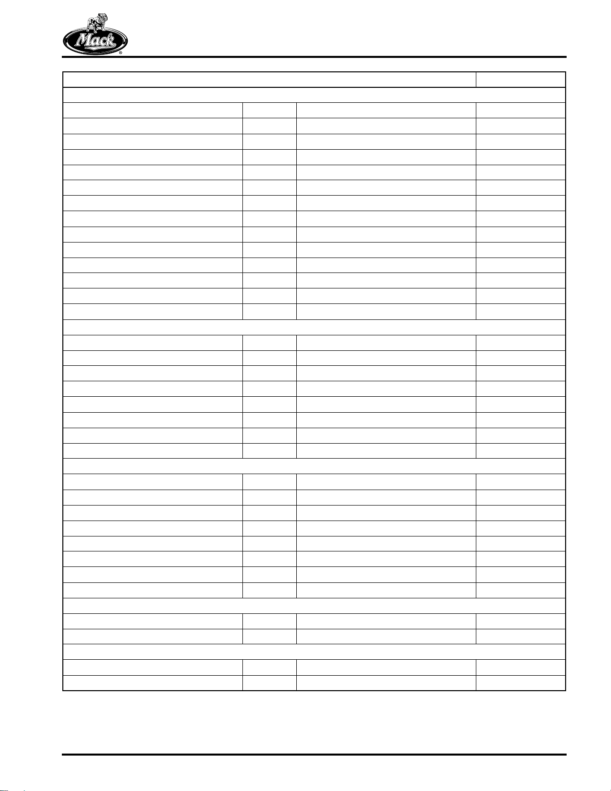
TABLE OF CONTENTS
TABLE OF CONTENTS
Page iii
Page 5

TABLE OF CONTENTS
INTRODUCTION . . . . . . . . . . . . . . . . . . . . . . . . . . . . . . . . . . . . . . . . . . . . . . . . . . . . . . . . . . . . . . . . . . . 1
SAFETY INFORMATION . . . . . . . . . . . . . . . . . . . . . . . . . . . . . . . . . . . . . . . . . . . . . . . . . . . . . . . . . . 2
Advisory Labels . . . . . . . . . . . . . . . . . . . . . . . . . . . . . . . . . . . . . . . . . . . . . . . . . . . . . . . . . . . . . . 2
Service Procedures and Tool Usage . . . . . . . . . . . . . . . . . . . . . . . . . . . . . . . . . . . . . . . . . . . . . . 3
EXPLANATION OF NUMERICAL CODE . . . . . . . . . . . . . . . . . . . . . . . . . . . . . . . . . . . . . . . . . . . . . 5
CONVERSION CHART . . . . . . . . . . . . . . . . . . . . . . . . . . . . . . . . . . . . . . . . . . . . . . . . . . . . . . . . . . . 6
ABOUT THE MACK MP8 ENGINE . . . . . . . . . . . . . . . . . . . . . . . . . . . . . . . . . . . . . . . . . . . . . . . . . . 9
Service Precautions Summary . . . . . . . . . . . . . . . . . . . . . . . . . . . . . . . . . . . . . . . . . . . . . . . . . . 11
VISUAL IDENTIFICATION . . . . . . . . . . . . . . . . . . . . . . . . . . . . . . . . . . . . . . . . . . . . . . . . . . . . . . . . . . 13
MP8 ENGINE MODEL IDENTIFICATION . . . . . . . . . . . . . . . . . . . . . . . . . . . . . . . . . . . . . . . . . . . . 14
Engine Information Plate . . . . . . . . . . . . . . . . . . . . . . . . . . . . . . . . . . . . . . . . . . . . . . . . . . . . . . 14
Engine Serial Number Identification . . . . . . . . . . . . . . . . . . . . . . . . . . . . . . . . . . . . . . . . . . . . . . 14
DESCRIPTION AND OPERATION . . . . . . . . . . . . . . . . . . . . . . . . . . . . . . . . . . . . . . . . . . . . . . . . . . . . 15
MACK MP8 US07 ENGINE DESIGN FEATURES . . . . . . . . . . . . . . . . . . . . . . . . . . . . . . . . . . . . . 16
Engine Components . . . . . . . . . . . . . . . . . . . . . . . . . . . . . . . . . . . . . . . . . . . . . . . . . . . . . . . . . 17
Lubrication System . . . . . . . . . . . . . . . . . . . . . . . . . . . . . . . . . . . . . . . . . . . . . . . . . . . . . . . . . . 25
Crankcase Ventilation . . . . . . . . . . . . . . . . . . . . . . . . . . . . . . . . . . . . . . . . . . . . . . . . . . . . . . . . 27
Fuel System . . . . . . . . . . . . . . . . . . . . . . . . . . . . . . . . . . . . . . . . . . . . . . . . . . . . . . . . . . . . . . . . 28
PowerLeash™ Engine Brake . . . . . . . . . . . . . . . . . . . . . . . . . . . . . . . . . . . . . . . . . . . . . . . . . . . 33
Exhaust Gas Recirculation System . . . . . . . . . . . . . . . . . . . . . . . . . . . . . . . . . . . . . . . . . . . . . . 34
Exhaust Aftertreatment System . . . . . . . . . . . . . . . . . . . . . . . . . . . . . . . . . . . . . . . . . . . . . . . . . 36
Air Intake System . . . . . . . . . . . . . . . . . . . . . . . . . . . . . . . . . . . . . . . . . . . . . . . . . . . . . . . . . . . . 39
Variable Geometry Turbocharger . . . . . . . . . . . . . . . . . . . . . . . . . . . . . . . . . . . . . . . . . . . . . . . 40
Cooling System . . . . . . . . . . . . . . . . . . . . . . . . . . . . . . . . . . . . . . . . . . . . . . . . . . . . . . . . . . . . . 40
Engine Management System . . . . . . . . . . . . . . . . . . . . . . . . . . . . . . . . . . . . . . . . . . . . . . . . . . . 41
GLOSSARY OF TERMS . . . . . . . . . . . . . . . . . . . . . . . . . . . . . . . . . . . . . . . . . . . . . . . . . . . . . . . . . 44
COMPONENT LOCATOR . . . . . . . . . . . . . . . . . . . . . . . . . . . . . . . . . . . . . . . . . . . . . . . . . . . . . . . . . . . 47
MP8 ENGINE COMPONENT LOCATION VIEWS . . . . . . . . . . . . . . . . . . . . . . . . . . . . . . . . . . . . . 48
TROUBLESHOOTING . . . . . . . . . . . . . . . . . . . . . . . . . . . . . . . . . . . . . . . . . . . . . . . . . . . . . . . . . . . . . 53
ENGINE SYMPTOM DIAGNOSIS . . . . . . . . . . . . . . . . . . . . . . . . . . . . . . . . . . . . . . . . . . . . . . . . . . 54
Troubleshooting Technique . . . . . . . . . . . . . . . . . . . . . . . . . . . . . . . . . . . . . . . . . . . . . . . . . . . .54
Noise and Vibration . . . . . . . . . . . . . . . . . . . . . . . . . . . . . . . . . . . . . . . . . . . . . . . . . . . . . . . . . . 55
ENGINE CHECKS AND TESTS . . . . . . . . . . . . . . . . . . . . . . . . . . . . . . . . . . . . . . . . . . . . . . . . . . . 56
Special Tools . . . . . . . . . . . . . . . . . . . . . . . . . . . . . . . . . . . . . . . . . . . . . . . . . . . . . . . . . . . . . . . 56
Camshaft Sensor Depth, Check . . . . . . . . . . . . . . . . . . . . . . . . . . . . . . . . . . . . . . . . . . . . . . . . 59
Camshaft Timing, Check . . . . . . . . . . . . . . . . . . . . . . . . . . . . . . . . . . . . . . . . . . . . . . . . . . . . . . 60
Crankcase Ventilation, Check . . . . . . . . . . . . . . . . . . . . . . . . . . . . . . . . . . . . . . . . . . . . . . . . . .60
Cylinder Head, Pressure Test . . . . . . . . . . . . . . . . . . . . . . . . . . . . . . . . . . . . . . . . . . . . . . . . . .61
Cylinder Liner and Piston Wear, Check . . . . . . . . . . . . . . . . . . . . . . . . . . . . . . . . . . . . . . . . . . . 63
EGR Cooler, Pressure Test . . . . . . . . . . . . . . . . . . . . . . . . . . . . . . . . . . . . . . . . . . . . . . . . . . . .64
Engine Compression, Test . . . . . . . . . . . . . . . . . . . . . . . . . . . . . . . . . . . . . . . . . . . . . . . . . . . . . 65
Flywheel Housing Runout, Check . . . . . . . . . . . . . . . . . . . . . . . . . . . . . . . . . . . . . . . . . . . . . . . 67
Oil Cooler, Pressure Test . . . . . . . . . . . . . . . . . . . . . . . . . . . . . . . . . . . . . . . . . . . . . . . . . . . . . . 69
Rocker Arm, Check . . . . . . . . . . . . . . . . . . . . . . . . . . . . . . . . . . . . . . . . . . . . . . . . . . . . . . . . . . 69
Thermostat, Check . . . . . . . . . . . . . . . . . . . . . . . . . . . . . . . . . . . . . . . . . . . . . . . . . . . . . . . . . . . 72
Valve Guide Wear, Check . . . . . . . . . . . . . . . . . . . . . . . . . . . . . . . . . . . . . . . . . . . . . . . . . . . . . 73
Page iv
Page 6

TABLE OF CONTENTS
MAINTENANCE . . . . . . . . . . . . . . . . . . . . . . . . . . . . . . . . . . . . . . . . . . . . . . . . . . . . . . . . . . . . . . . . . . 75
LUBRICATION SYSTEM MAINTENANCE . . . . . . . . . . . . . . . . . . . . . . . . . . . . . . . . . . . . . . . . . . . 76
Special Tool . . . . . . . . . . . . . . . . . . . . . . . . . . . . . . . . . . . . . . . . . . . . . . . . . . . . . . . . . . . . . . . . 76
Oil Level Check . . . . . . . . . . . . . . . . . . . . . . . . . . . . . . . . . . . . . . . . . . . . . . . . . . . . . . . . . . . . . 76
Oil and Filter Change Procedure . . . . . . . . . . . . . . . . . . . . . . . . . . . . . . . . . . . . . . . . . . . . . . . .77
Crankcase Ventilation System . . . . . . . . . . . . . . . . . . . . . . . . . . . . . . . . . . . . . . . . . . . . . . . . . .77
FUEL FILTER REPLACEMENT . . . . . . . . . . . . . . . . . . . . . . . . . . . . . . . . . . . . . . . . . . . . . . . . . . . 78
Fuel Filter Change . . . . . . . . . . . . . . . . . . . . . . . . . . . . . . . . . . . . . . . . . . . . . . . . . . . . . . . . . . . 78
COOLING SYSTEM MAINTENANCE . . . . . . . . . . . . . . . . . . . . . . . . . . . . . . . . . . . . . . . . . . . . . . . 79
Special Tool . . . . . . . . . . . . . . . . . . . . . . . . . . . . . . . . . . . . . . . . . . . . . . . . . . . . . . . . . . . . . . . . 79
Coolant Drain Outlets . . . . . . . . . . . . . . . . . . . . . . . . . . . . . . . . . . . . . . . . . . . . . . . . . . . . . . . . . 80
Coolant Filter . . . . . . . . . . . . . . . . . . . . . . . . . . . . . . . . . . . . . . . . . . . . . . . . . . . . . . . . . . . . . . . 80
EXHAUST AFTERTREATMENT SYSTEM MAINTENANCE . . . . . . . . . . . . . . . . . . . . . . . . . . . . . 81
Special Tools . . . . . . . . . . . . . . . . . . . . . . . . . . . . . . . . . . . . . . . . . . . . . . . . . . . . . . . . . . . . . . . 81
Diesel Particulate Filter . . . . . . . . . . . . . . . . . . . . . . . . . . . . . . . . . . . . . . . . . . . . . . . . . . . . . . . 82
Aftertreatment Fuel Injector (AFI) . . . . . . . . . . . . . . . . . . . . . . . . . . . . . . . . . . . . . . . . . . . . . . . . 87
DRIVE BELT REPLACEMENT AND TENSIONING . . . . . . . . . . . . . . . . . . . . . . . . . . . . . . . . . . . . 90
General Information . . . . . . . . . . . . . . . . . . . . . . . . . . . . . . . . . . . . . . . . . . . . . . . . . . . . . . . . . . 90
Automatically Tensioned System . . . . . . . . . . . . . . . . . . . . . . . . . . . . . . . . . . . . . . . . . . . . . . . . 90
REPAIR INSTRUCTIONS, PART 1 . . . . . . . . . . . . . . . . . . . . . . . . . . . . . . . . . . . . . . . . . . . . . . . . . . . . 91
ENGINE REMOVAL . . . . . . . . . . . . . . . . . . . . . . . . . . . . . . . . . . . . . . . . . . . . . . . . . . . . . . . . . . . . . 92
Special Tools . . . . . . . . . . . . . . . . . . . . . . . . . . . . . . . . . . . . . . . . . . . . . . . . . . . . . . . . . . . . . . . 92
General Instructions . . . . . . . . . . . . . . . . . . . . . . . . . . . . . . . . . . . . . . . . . . . . . . . . . . . . . . . . . . 93
Removal . . . . . . . . . . . . . . . . . . . . . . . . . . . . . . . . . . . . . . . . . . . . . . . . . . . . . . . . . . . . . . . . . . . 93
ENGINE DISASSEMBLY . . . . . . . . . . . . . . . . . . . . . . . . . . . . . . . . . . . . . . . . . . . . . . . . . . . . . . . . . 96
Special Tools . . . . . . . . . . . . . . . . . . . . . . . . . . . . . . . . . . . . . . . . . . . . . . . . . . . . . . . . . . . . . . . 96
General Instructions . . . . . . . . . . . . . . . . . . . . . . . . . . . . . . . . . . . . . . . . . . . . . . . . . . . . . . . . . . 99
Mounting the Engine on a Repair Stand . . . . . . . . . . . . . . . . . . . . . . . . . . . . . . . . . . . . . . . . . . 99
EGR Crossover Piping Removal . . . . . . . . . . . . . . . . . . . . . . . . . . . . . . . . . . . . . . . . . . . . . . . 101
EGR Venturi Tube Removal . . . . . . . . . . . . . . . . . . . . . . . . . . . . . . . . . . . . . . . . . . . . . . . . . . . 102
Cylinder Head (Valve) Cover Removal . . . . . . . . . . . . . . . . . . . . . . . . . . . . . . . . . . . . . . . . . . 102
Engine Wiring Harness Removal . . . . . . . . . . . . . . . . . . . . . . . . . . . . . . . . . . . . . . . . . . . . . . . 103
Aftertreatment Fuel Injector (AFI) and Diffuser Removal . . . . . . . . . . . . . . . . . . . . . . . . . . . . . 104
Timing Gear Cover Removal . . . . . . . . . . . . . . . . . . . . . . . . . . . . . . . . . . . . . . . . . . . . . . . . . . 104
Camshaft Gear and Vibration Damper Removal . . . . . . . . . . . . . . . . . . . . . . . . . . . . . . . . . . . 106
Rocker Arm Shaft Removal . . . . . . . . . . . . . . . . . . . . . . . . . . . . . . . . . . . . . . . . . . . . . . . . . . . 106
Valve Yoke (Bridge) Removal . . . . . . . . . . . . . . . . . . . . . . . . . . . . . . . . . . . . . . . . . . . . . . . . . 108
Camshaft Removal . . . . . . . . . . . . . . . . . . . . . . . . . . . . . . . . . . . . . . . . . . . . . . . . . . . . . . . . . . 109
Unit Injector Removal . . . . . . . . . . . . . . . . . . . . . . . . . . . . . . . . . . . . . . . . . . . . . . . . . . . . . . . . 110
Starter Removal . . . . . . . . . . . . . . . . . . . . . . . . . . . . . . . . . . . . . . . . . . . . . . . . . . . . . . . . . . . . 115
Turbocharger Removal . . . . . . . . . . . . . . . . . . . . . . . . . . . . . . . . . . . . . . . . . . . . . . . . . . . . . . 116
EGR Hot Pipe (Cooler Inlet) Removal . . . . . . . . . . . . . . . . . . . . . . . . . . . . . . . . . . . . . . . . . . . 118
EGR Valve Removal . . . . . . . . . . . . . . . . . . . . . . . . . . . . . . . . . . . . . . . . . . . . . . . . . . . . . . . . 118
EGR Cooler Removal . . . . . . . . . . . . . . . . . . . . . . . . . . . . . . . . . . . . . . . . . . . . . . . . . . . . . . . . 120
Exhaust Manifold Removal . . . . . . . . . . . . . . . . . . . . . . . . . . . . . . . . . . . . . . . . . . . . . . . . . . . 121
Oil Filter Housing Removal . . . . . . . . . . . . . . . . . . . . . . . . . . . . . . . . . . . . . . . . . . . . . . . . . . . 122
Coolant and Pump Inlet Housings Removal . . . . . . . . . . . . . . . . . . . . . . . . . . . . . . . . . . . . . . 122
Cooling Duct Cover and Oil Cooler Removal . . . . . . . . . . . . . . . . . . . . . . . . . . . . . . . . . . . . . . 123
Drive Belts and Fan Hub Removal . . . . . . . . . . . . . . . . . . . . . . . . . . . . . . . . . . . . . . . . . . . . . . 124
EGR Mixer Removal . . . . . . . . . . . . . . . . . . . . . . . . . . . . . . . . . . . . . . . . . . . . . . . . . . . . . . . . 125
Crankcase Ventilation (CCV) Separator Removal . . . . . . . . . . . . . . . . . . . . . . . . . . . . . . . . . . 125
Page v
Page 7

TABLE OF CONTENTS
Fuel Lines and Filter Housing Removal . . . . . . . . . . . . . . . . . . . . . . . . . . . . . . . . . . . . . . . . . . 126
EECU and Cooling Plate Removal . . . . . . . . . . . . . . . . . . . . . . . . . . . . . . . . . . . . . . . . . . . . . 127
Inlet Manifold Removal . . . . . . . . . . . . . . . . . . . . . . . . . . . . . . . . . . . . . . . . . . . . . . . . . . . . . . 129
Tandem Pump (Fuel and Power Steering) Removal . . . . . . . . . . . . . . . . . . . . . . . . . . . . . . . . 129
Air Compressor Removal . . . . . . . . . . . . . . . . . . . . . . . . . . . . . . . . . . . . . . . . . . . . . . . . . . . . . 129
Flywheel and Pilot Bearing Removal . . . . . . . . . . . . . . . . . . . . . . . . . . . . . . . . . . . . . . . . . . . . 130
Power Take-Off (PTO) Assembly Removal . . . . . . . . . . . . . . . . . . . . . . . . . . . . . . . . . . . . . . . 131
Flywheel Housing Removal . . . . . . . . . . . . . . . . . . . . . . . . . . . . . . . . . . . . . . . . . . . . . . . . . . . 131
Crankshaft Rear Seal Removal . . . . . . . . . . . . . . . . . . . . . . . . . . . . . . . . . . . . . . . . . . . . . . . . 132
Timing Gear Train Removal . . . . . . . . . . . . . . . . . . . . . . . . . . . . . . . . . . . . . . . . . . . . . . . . . . . 132
Timing Gear Plate Removal . . . . . . . . . . . . . . . . . . . . . . . . . . . . . . . . . . . . . . . . . . . . . . . . . . . 134
Alternator and Refrigerant Compressor Removal . . . . . . . . . . . . . . . . . . . . . . . . . . . . . . . . . . 134
Thermostat and Cover Removal . . . . . . . . . . . . . . . . . . . . . . . . . . . . . . . . . . . . . . . . . . . . . . . 135
Coolant Pump Removal . . . . . . . . . . . . . . . . . . . . . . . . . . . . . . . . . . . . . . . . . . . . . . . . . . . . . . 135
Cylinder Head Removal . . . . . . . . . . . . . . . . . . . . . . . . . . . . . . . . . . . . . . . . . . . . . . . . . . . . . . 136
Crankshaft Vibration Damper and Fan Pulley Removal . . . . . . . . . . . . . . . . . . . . . . . . . . . . . 138
Crankshaft Front Cover Removal . . . . . . . . . . . . . . . . . . . . . . . . . . . . . . . . . . . . . . . . . . . . . . 138
Crankshaft Front Seal Removal . . . . . . . . . . . . . . . . . . . . . . . . . . . . . . . . . . . . . . . . . . . . . . . . 138
Oil Fill Pipe and Dipstick Retainer Removal . . . . . . . . . . . . . . . . . . . . . . . . . . . . . . . . . . . . . . 139
Oil Pan Removal . . . . . . . . . . . . . . . . . . . . . . . . . . . . . . . . . . . . . . . . . . . . . . . . . . . . . . . . . . . 139
Front Engine Support Removal . . . . . . . . . . . . . . . . . . . . . . . . . . . . . . . . . . . . . . . . . . . . . . . . 140
Block Stiffener Plate Removal . . . . . . . . . . . . . . . . . . . . . . . . . . . . . . . . . . . . . . . . . . . . . . . . . 140
Oil Pump Removal . . . . . . . . . . . . . . . . . . . . . . . . . . . . . . . . . . . . . . . . . . . . . . . . . . . . . . . . . . 141
Piston and Connecting Rod Assembly Removal . . . . . . . . . . . . . . . . . . . . . . . . . . . . . . . . . . . 142
Main Bearing Cap Removal . . . . . . . . . . . . . . . . . . . . . . . . . . . . . . . . . . . . . . . . . . . . . . . . . . . 143
Crankshaft Removal . . . . . . . . . . . . . . . . . . . . . . . . . . . . . . . . . . . . . . . . . . . . . . . . . . . . . . . . 144
CYLINDER BLOCK RECONDITIONING . . . . . . . . . . . . . . . . . . . . . . . . . . . . . . . . . . . . . . . . . . . . 145
Tools and Equipment . . . . . . . . . . . . . . . . . . . . . . . . . . . . . . . . . . . . . . . . . . . . . . . . . . . . . . . . 145
Piston Cooling Spray Nozzle Removal . . . . . . . . . . . . . . . . . . . . . . . . . . . . . . . . . . . . . . . . . . 146
Cylinder Liner Removal . . . . . . . . . . . . . . . . . . . . . . . . . . . . . . . . . . . . . . . . . . . . . . . . . . . . . . 146
Block Cleaning and Inspection . . . . . . . . . . . . . . . . . . . . . . . . . . . . . . . . . . . . . . . . . . . . . . . . . 147
Liner Height Measurement . . . . . . . . . . . . . . . . . . . . . . . . . . . . . . . . . . . . . . . . . . . . . . . . . . . . 148
Cylinder Liner Installation . . . . . . . . . . . . . . . . . . . . . . . . . . . . . . . . . . . . . . . . . . . . . . . . . . . . . 149
FLYWHEEL BENCH PROCEDURES . . . . . . . . . . . . . . . . . . . . . . . . . . . . . . . . . . . . . . . . . . . . . . 150
Flywheel Ring Gear Replacement . . . . . . . . . . . . . . . . . . . . . . . . . . . . . . . . . . . . . . . . . . . . . . 150
CONNECTING ROD AND PISTON BENCH PROCEDURES . . . . . . . . . . . . . . . . . . . . . . . . . . . . 151
Connecting Rod — Piston Disassembly . . . . . . . . . . . . . . . . . . . . . . . . . . . . . . . . . . . . . . . . . 151
Piston Inspection and Cleaning . . . . . . . . . . . . . . . . . . . . . . . . . . . . . . . . . . . . . . . . . . . . . . . . 152
Piston Ring Inspection and Replacement . . . . . . . . . . . . . . . . . . . . . . . . . . . . . . . . . . . . . . . . 153
Connecting Rod — Piston Assembly . . . . . . . . . . . . . . . . . . . . . . . . . . . . . . . . . . . . . . . . . . . . 154
CYLINDER HEAD OVERHAUL . . . . . . . . . . . . . . . . . . . . . . . . . . . . . . . . . . . . . . . . . . . . . . . . . . . 156
Tools and Equipment . . . . . . . . . . . . . . . . . . . . . . . . . . . . . . . . . . . . . . . . . . . . . . . . . . . . . . . . 156
Inlet and Exhaust Valve Removal . . . . . . . . . . . . . . . . . . . . . . . . . . . . . . . . . . . . . . . . . . . . . . 160
Cylinder Head Cleaning and Inspection . . . . . . . . . . . . . . . . . . . . . . . . . . . . . . . . . . . . . . . . . . 161
Valve Guide Replacement . . . . . . . . . . . . . . . . . . . . . . . . . . . . . . . . . . . . . . . . . . . . . . . . . . . . 161
Valve Spring Inspection . . . . . . . . . . . . . . . . . . . . . . . . . . . . . . . . . . . . . . . . . . . . . . . . . . . . . . 163
Injector Sleeve Replacement . . . . . . . . . . . . . . . . . . . . . . . . . . . . . . . . . . . . . . . . . . . . . . . . . . 164
Expansion Plug Replacement . . . . . . . . . . . . . . . . . . . . . . . . . . . . . . . . . . . . . . . . . . . . . . . . . 171
Valve Inspection . . . . . . . . . . . . . . . . . . . . . . . . . . . . . . . . . . . . . . . . . . . . . . . . . . . . . . . . . . . . 171
Valve Installation . . . . . . . . . . . . . . . . . . . . . . . . . . . . . . . . . . . . . . . . . . . . . . . . . . . . . . . . . . . 172
Page vi
Page 8

TABLE OF CONTENTS
ROCKER ARM SHAFT BENCH PROCEDURES . . . . . . . . . . . . . . . . . . . . . . . . . . . . . . . . . . . . . 173
Description . . . . . . . . . . . . . . . . . . . . . . . . . . . . . . . . . . . . . . . . . . . . . . . . . . . . . . . . . . . . . . . . 173
Rocker Arm Shaft Disassembly . . . . . . . . . . . . . . . . . . . . . . . . . . . . . . . . . . . . . . . . . . . . . . . . 174
Inspection . . . . . . . . . . . . . . . . . . . . . . . . . . . . . . . . . . . . . . . . . . . . . . . . . . . . . . . . . . . . . . . . . 174
Rocker Arm Shaft Assembly . . . . . . . . . . . . . . . . . . . . . . . . . . . . . . . . . . . . . . . . . . . . . . . . . . 174
CAMSHAFT BENCH PROCEDURES . . . . . . . . . . . . . . . . . . . . . . . . . . . . . . . . . . . . . . . . . . . . . . 175
Camshaft Inspection . . . . . . . . . . . . . . . . . . . . . . . . . . . . . . . . . . . . . . . . . . . . . . . . . . . . . . . . 175
COOLING SYSTEM COMPONENTS BENCH PROCEDURES . . . . . . . . . . . . . . . . . . . . . . . . . . 176
Special Tools . . . . . . . . . . . . . . . . . . . . . . . . . . . . . . . . . . . . . . . . . . . . . . . . . . . . . . . . . . . . . . 176
Oil Cooler Reconditioning . . . . . . . . . . . . . . . . . . . . . . . . . . . . . . . . . . . . . . . . . . . . . . . . . . . . 177
EGR Cooler Cleaning . . . . . . . . . . . . . . . . . . . . . . . . . . . . . . . . . . . . . . . . . . . . . . . . . . . . . . . . 177
EGR Cooler Pressure Test . . . . . . . . . . . . . . . . . . . . . . . . . . . . . . . . . . . . . . . . . . . . . . . . . . . 179
ENGINE REASSEMBLY . . . . . . . . . . . . . . . . . . . . . . . . . . . . . . . . . . . . . . . . . . . . . . . . . . . . . . . . 182
Special Tools . . . . . . . . . . . . . . . . . . . . . . . . . . . . . . . . . . . . . . . . . . . . . . . . . . . . . . . . . . . . . . 182
General Instructions . . . . . . . . . . . . . . . . . . . . . . . . . . . . . . . . . . . . . . . . . . . . . . . . . . . . . . . . . 187
Crankshaft Installation . . . . . . . . . . . . . . . . . . . . . . . . . . . . . . . . . . . . . . . . . . . . . . . . . . . . . . . 187
Main Bearing Cap Installation . . . . . . . . . . . . . . . . . . . . . . . . . . . . . . . . . . . . . . . . . . . . . . . . . 188
Piston and Connecting Rod Assembly Installation . . . . . . . . . . . . . . . . . . . . . . . . . . . . . . . . . . 190
Oil Pump and Block Stiffener Plate Installation . . . . . . . . . . . . . . . . . . . . . . . . . . . . . . . . . . . .193
Oil Pump Pipes and Strainer Installation . . . . . . . . . . . . . . . . . . . . . . . . . . . . . . . . . . . . . . . . . 194
Front Engine Support Installation . . . . . . . . . . . . . . . . . . . . . . . . . . . . . . . . . . . . . . . . . . . . . . . 195
Crankshaft Front Cover and Seal Installation . . . . . . . . . . . . . . . . . . . . . . . . . . . . . . . . . . . . . 195
Timing Gear Plate Installation . . . . . . . . . . . . . . . . . . . . . . . . . . . . . . . . . . . . . . . . . . . . . . . . . 197
Cylinder Head Installation . . . . . . . . . . . . . . . . . . . . . . . . . . . . . . . . . . . . . . . . . . . . . . . . . . . . 198
Camshaft Installation . . . . . . . . . . . . . . . . . . . . . . . . . . . . . . . . . . . . . . . . . . . . . . . . . . . . . . . . 201
Timing Gear Train Installation . . . . . . . . . . . . . . . . . . . . . . . . . . . . . . . . . . . . . . . . . . . . . . . . . 202
Unit Injector Installation . . . . . . . . . . . . . . . . . . . . . . . . . . . . . . . . . . . . . . . . . . . . . . . . . . . . . . 205
Valve Yoke (Bridge) Installation . . . . . . . . . . . . . . . . . . . . . . . . . . . . . . . . . . . . . . . . . . . . . . . . 208
Rocker Arm Shaft and Engine Brake Installation . . . . . . . . . . . . . . . . . . . . . . . . . . . . . . . . . . . 209
Flywheel Housing Installation . . . . . . . . . . . . . . . . . . . . . . . . . . . . . . . . . . . . . . . . . . . . . . . . . . 212
Crankshaft Rear Seal Installation . . . . . . . . . . . . . . . . . . . . . . . . . . . . . . . . . . . . . . . . . . . . . . . 213
Flywheel and Pilot Bearing Installation . . . . . . . . . . . . . . . . . . . . . . . . . . . . . . . . . . . . . . . . . . 214
Oil Pan Installation . . . . . . . . . . . . . . . . . . . . . . . . . . . . . . . . . . . . . . . . . . . . . . . . . . . . . . . . . . 216
Oil Filler Pipe and Dipstick Pipe Installation . . . . . . . . . . . . . . . . . . . . . . . . . . . . . . . . . . . . . . . 218
Power Take-Off Installation . . . . . . . . . . . . . . . . . . . . . . . . . . . . . . . . . . . . . . . . . . . . . . . . . . . 218
Timing Gear Cover Installation . . . . . . . . . . . . . . . . . . . . . . . . . . . . . . . . . . . . . . . . . . . . . . . . . 219
Coolant Pump Installation . . . . . . . . . . . . . . . . . . . . . . . . . . . . . . . . . . . . . . . . . . . . . . . . . . . . 221
Thermostat and Cover Installation . . . . . . . . . . . . . . . . . . . . . . . . . . . . . . . . . . . . . . . . . . . . . . 222
Coolant Pipe Installation . . . . . . . . . . . . . . . . . . . . . . . . . . . . . . . . . . . . . . . . . . . . . . . . . . . . . 222
Oil Cooler and Cooling Duct Cover Installation . . . . . . . . . . . . . . . . . . . . . . . . . . . . . . . . . . . . 223
Oil Filter Housing Installation . . . . . . . . . . . . . . . . . . . . . . . . . . . . . . . . . . . . . . . . . . . . . . . . . . 225
Exhaust Manifold Installation . . . . . . . . . . . . . . . . . . . . . . . . . . . . . . . . . . . . . . . . . . . . . . . . . . 226
EGR Valve Installation . . . . . . . . . . . . . . . . . . . . . . . . . . . . . . . . . . . . . . . . . . . . . . . . . . . . . . . 227
EGR Cooler Installation . . . . . . . . . . . . . . . . . . . . . . . . . . . . . . . . . . . . . . . . . . . . . . . . . . . . . . 229
EGR Hot Pipe (Cooler Inlet) Installation . . . . . . . . . . . . . . . . . . . . . . . . . . . . . . . . . . . . . . . . . . 230
Turbocharger Installation . . . . . . . . . . . . . . . . . . . . . . . . . . . . . . . . . . . . . . . . . . . . . . . . . . . . . 232
Starter Installation . . . . . . . . . . . . . . . . . . . . . . . . . . . . . . . . . . . . . . . . . . . . . . . . . . . . . . . . . . 235
Air Compressor Installation . . . . . . . . . . . . . . . . . . . . . . . . . . . . . . . . . . . . . . . . . . . . . . . . . . . 235
Tandem Pump (Fuel and Power Steering) Installation . . . . . . . . . . . . . . . . . . . . . . . . . . . . . . 237
Inlet Manifold Installation . . . . . . . . . . . . . . . . . . . . . . . . . . . . . . . . . . . . . . . . . . . . . . . . . . . . . 237
EGR Mixer Installation . . . . . . . . . . . . . . . . . . . . . . . . . . . . . . . . . . . . . . . . . . . . . . . . . . . . . . . 238
Page vii
Page 9

TABLE OF CONTENTS
EECU and Cooler Installation . . . . . . . . . . . . . . . . . . . . . . . . . . . . . . . . . . . . . . . . . . . . . . . . . 239
Fuel Lines and Filter Housing Installation . . . . . . . . . . . . . . . . . . . . . . . . . . . . . . . . . . . . . . . . 240
Crankcase Ventilation Separator . . . . . . . . . . . . . . . . . . . . . . . . . . . . . . . . . . . . . . . . . . . . . . . 241
Crankshaft Vibration Damper and Fan Pulley Installation . . . . . . . . . . . . . . . . . . . . . . . . . . . . 242
Alternator and Refrigerant Compressor Installation . . . . . . . . . . . . . . . . . . . . . . . . . . . . . . . . . 243
Wiring Harness Installation . . . . . . . . . . . . . . . . . . . . . . . . . . . . . . . . . . . . . . . . . . . . . . . . . . . 243
Cylinder Head (Valve) Cover Installation . . . . . . . . . . . . . . . . . . . . . . . . . . . . . . . . . . . . . . . . . 245
EGR Venturi Tube and Crossover Piping Installation . . . . . . . . . . . . . . . . . . . . . . . . . . . . . . . 246
Fan Hub and Drive Belt Installation . . . . . . . . . . . . . . . . . . . . . . . . . . . . . . . . . . . . . . . . . . . . . 248
Removing Engine from Engine Stand . . . . . . . . . . . . . . . . . . . . . . . . . . . . . . . . . . . . . . . . . . . 249
Filters and Miscellaneous Components Installation . . . . . . . . . . . . . . . . . . . . . . . . . . . . . . . . . 250
ENGINE INSTALLATION . . . . . . . . . . . . . . . . . . . . . . . . . . . . . . . . . . . . . . . . . . . . . . . . . . . . . . . 251
Special Tools . . . . . . . . . . . . . . . . . . . . . . . . . . . . . . . . . . . . . . . . . . . . . . . . . . . . . . . . . . . . . . 251
General Instructions . . . . . . . . . . . . . . . . . . . . . . . . . . . . . . . . . . . . . . . . . . . . . . . . . . . . . . . . . 251
Installation . . . . . . . . . . . . . . . . . . . . . . . . . . . . . . . . . . . . . . . . . . . . . . . . . . . . . . . . . . . . . . . . 252
REPAIR INSTRUCTIONS, PART 2 . . . . . . . . . . . . . . . . . . . . . . . . . . . . . . . . . . . . . . . . . . . . . . . . . . 255
IN-CHASSIS PART/COMPONENT PROCEDURES . . . . . . . . . . . . . . . . . . . . . . . . . . . . . . . . . . . 256
CAMSHAFT BEARING BRACKETS, REPLACEMENT . . . . . . . . . . . . . . . . . . . . . . . . . . . . . . . . . 256
Preliminary Steps . . . . . . . . . . . . . . . . . . . . . . . . . . . . . . . . . . . . . . . . . . . . . . . . . . . . . . . . . . . 256
General Information . . . . . . . . . . . . . . . . . . . . . . . . . . . . . . . . . . . . . . . . . . . . . . . . . . . . . . . . . 256
Camshaft Inspection . . . . . . . . . . . . . . . . . . . . . . . . . . . . . . . . . . . . . . . . . . . . . . . . . . . . . . . . 257
Bracket Replacement Procedure . . . . . . . . . . . . . . . . . . . . . . . . . . . . . . . . . . . . . . . . . . . . . . . 257
Final Steps . . . . . . . . . . . . . . . . . . . . . . . . . . . . . . . . . . . . . . . . . . . . . . . . . . . . . . . . . . . . . . . . 258
OIL THERMOSTAT AND PRESSURE SAFETY VALVE REPLACEMENT . . . . . . . . . . . . . . . . . 259
Pressure Safety Valve Removal . . . . . . . . . . . . . . . . . . . . . . . . . . . . . . . . . . . . . . . . . . . . . . . 259
Oil Thermostat Valve Replacement . . . . . . . . . . . . . . . . . . . . . . . . . . . . . . . . . . . . . . . . . . . . . 260
CRANKSHAFT FRONT SEAL REPLACEMENT . . . . . . . . . . . . . . . . . . . . . . . . . . . . . . . . . . . . . . 261
Special Tools . . . . . . . . . . . . . . . . . . . . . . . . . . . . . . . . . . . . . . . . . . . . . . . . . . . . . . . . . . . . . . 261
Seal Removal . . . . . . . . . . . . . . . . . . . . . . . . . . . . . . . . . . . . . . . . . . . . . . . . . . . . . . . . . . . . . . 262
Seal Installation . . . . . . . . . . . . . . . . . . . . . . . . . . . . . . . . . . . . . . . . . . . . . . . . . . . . . . . . . . . . 262
CRANKSHAFT REAR SEAL REPLACEMENT . . . . . . . . . . . . . . . . . . . . . . . . . . . . . . . . . . . . . . . 264
Special Tools . . . . . . . . . . . . . . . . . . . . . . . . . . . . . . . . . . . . . . . . . . . . . . . . . . . . . . . . . . . . . . 264
Neoprene Seal Removal . . . . . . . . . . . . . . . . . . . . . . . . . . . . . . . . . . . . . . . . . . . . . . . . . . . . . 264
Neoprene Seal Installation . . . . . . . . . . . . . . . . . . . . . . . . . . . . . . . . . . . . . . . . . . . . . . . . . . . . 265
Teflon
Teflon
CRANKCASE VENTILATION (CCV) SEPARATOR REPLACEMENT . . . . . . . . . . . . . . . . . . . . . 268
CCV Separator Removal . . . . . . . . . . . . . . . . . . . . . . . . . . . . . . . . . . . . . . . . . . . . . . . . . . . . . 268
CCV Separator Installation . . . . . . . . . . . . . . . . . . . . . . . . . . . . . . . . . . . . . . . . . . . . . . . . . . . 268
OIL PUMP REPLACEMENT (IN CHASSIS) . . . . . . . . . . . . . . . . . . . . . . . . . . . . . . . . . . . . . . . . . 269
Special Tools . . . . . . . . . . . . . . . . . . . . . . . . . . . . . . . . . . . . . . . . . . . . . . . . . . . . . . . . . . . . . . 269
Oil Pump Removal . . . . . . . . . . . . . . . . . . . . . . . . . . . . . . . . . . . . . . . . . . . . . . . . . . . . . . . . . . 270
Oil Pump Installation . . . . . . . . . . . . . . . . . . . . . . . . . . . . . . . . . . . . . . . . . . . . . . . . . . . . . . . . 270
INJECTOR COPPER SLEEVE REPLACEMENT . . . . . . . . . . . . . . . . . . . . . . . . . . . . . . . . . . . . . 272
Tools and Equipment . . . . . . . . . . . . . . . . . . . . . . . . . . . . . . . . . . . . . . . . . . . . . . . . . . . . . . . . 272
Preliminary Steps . . . . . . . . . . . . . . . . . . . . . . . . . . . . . . . . . . . . . . . . . . . . . . . . . . . . . . . . . . . 274
Copper Sleeve Removal . . . . . . . . . . . . . . . . . . . . . . . . . . . . . . . . . . . . . . . . . . . . . . . . . . . . . 274
Copper Sleeve Installation . . . . . . . . . . . . . . . . . . . . . . . . . . . . . . . . . . . . . . . . . . . . . . . . . . . . 278
Final Steps . . . . . . . . . . . . . . . . . . . . . . . . . . . . . . . . . . . . . . . . . . . . . . . . . . . . . . . . . . . . . . . . 281
®
Seal Removal . . . . . . . . . . . . . . . . . . . . . . . . . . . . . . . . . . . . . . . . . . . . . . . . . . . . . . . 266
®
Seal Installation . . . . . . . . . . . . . . . . . . . . . . . . . . . . . . . . . . . . . . . . . . . . . . . . . . . . . 266
Page viii
Page 10

TABLE OF CONTENTS
UNIT INJECTOR CLEANING . . . . . . . . . . . . . . . . . . . . . . . . . . . . . . . . . . . . . . . . . . . . . . . . . . . . 282
Preliminary Steps . . . . . . . . . . . . . . . . . . . . . . . . . . . . . . . . . . . . . . . . . . . . . . . . . . . . . . . . . . . 282
Cleaning and Inspection . . . . . . . . . . . . . . . . . . . . . . . . . . . . . . . . . . . . . . . . . . . . . . . . . . . . . 282
Final Steps . . . . . . . . . . . . . . . . . . . . . . . . . . . . . . . . . . . . . . . . . . . . . . . . . . . . . . . . . . . . . . . . 283
TURBOCHARGER SMART REMOTE ACTUATOR (SRA) REPLACEMENT . . . . . . . . . . . . . . . . 284
Preliminary Steps . . . . . . . . . . . . . . . . . . . . . . . . . . . . . . . . . . . . . . . . . . . . . . . . . . . . . . . . . . . 284
Turbocharger SRA Removal . . . . . . . . . . . . . . . . . . . . . . . . . . . . . . . . . . . . . . . . . . . . . . . . . . 284
Turbocharger SRA Inspection and Installation . . . . . . . . . . . . . . . . . . . . . . . . . . . . . . . . . . . . . 286
Final Assembly . . . . . . . . . . . . . . . . . . . . . . . . . . . . . . . . . . . . . . . . . . . . . . . . . . . . . . . . . . . . . 289
VALVE STEM HEIGHT MEASUREMENT PROCEDURE . . . . . . . . . . . . . . . . . . . . . . . . . . . . . . . 290
VALVE STEM SEAL REPLACEMENT . . . . . . . . . . . . . . . . . . . . . . . . . . . . . . . . . . . . . . . . . . . . . 293
Special Tools . . . . . . . . . . . . . . . . . . . . . . . . . . . . . . . . . . . . . . . . . . . . . . . . . . . . . . . . . . . . . . 293
Preliminary Steps . . . . . . . . . . . . . . . . . . . . . . . . . . . . . . . . . . . . . . . . . . . . . . . . . . . . . . . . . . . 294
Seal Removal . . . . . . . . . . . . . . . . . . . . . . . . . . . . . . . . . . . . . . . . . . . . . . . . . . . . . . . . . . . . . . 294
Seal Installation . . . . . . . . . . . . . . . . . . . . . . . . . . . . . . . . . . . . . . . . . . . . . . . . . . . . . . . . . . . . 295
Final Steps . . . . . . . . . . . . . . . . . . . . . . . . . . . . . . . . . . . . . . . . . . . . . . . . . . . . . . . . . . . . . . . . 295
REPAIR INSTRUCTIONS, PART 3 . . . . . . . . . . . . . . . . . . . . . . . . . . . . . . . . . . . . . . . . . . . . . . . . . . . 297
MP8 ENGINE SETUP AND ADJUSTMENT . . . . . . . . . . . . . . . . . . . . . . . . . . . . . . . . . . . . . . . . . 298
Special Tools . . . . . . . . . . . . . . . . . . . . . . . . . . . . . . . . . . . . . . . . . . . . . . . . . . . . . . . . . . . . . . 298
Valve and Unit Injector Adjustment . . . . . . . . . . . . . . . . . . . . . . . . . . . . . . . . . . . . . . . . . . . . . 300
Checking and Adjusting Timing Gear Backlash . . . . . . . . . . . . . . . . . . . . . . . . . . . . . . . . . . . . 305
ENGINE FINAL PREPARATION AND OPERATIONAL CHECK . . . . . . . . . . . . . . . . . . . . . . . . . 309
Filter Element Installation . . . . . . . . . . . . . . . . . . . . . . . . . . . . . . . . . . . . . . . . . . . . . . . . . . . . . 309
Engine Lubrication System . . . . . . . . . . . . . . . . . . . . . . . . . . . . . . . . . . . . . . . . . . . . . . . . . . . 309
Turbocharger . . . . . . . . . . . . . . . . . . . . . . . . . . . . . . . . . . . . . . . . . . . . . . . . . . . . . . . . . . . . . . 310
Cooling System . . . . . . . . . . . . . . . . . . . . . . . . . . . . . . . . . . . . . . . . . . . . . . . . . . . . . . . . . . . . 310
Fuel System . . . . . . . . . . . . . . . . . . . . . . . . . . . . . . . . . . . . . . . . . . . . . . . . . . . . . . . . . . . . . . . 310
Engine Operational Check . . . . . . . . . . . . . . . . . . . . . . . . . . . . . . . . . . . . . . . . . . . . . . . . . . . . 312
REBUILT ENGINE RUN-IN PROCEDURES . . . . . . . . . . . . . . . . . . . . . . . . . . . . . . . . . . . . . . . . . 312
General . . . . . . . . . . . . . . . . . . . . . . . . . . . . . . . . . . . . . . . . . . . . . . . . . . . . . . . . . . . . . . . . . . 312
Run-In Check . . . . . . . . . . . . . . . . . . . . . . . . . . . . . . . . . . . . . . . . . . . . . . . . . . . . . . . . . . . . . . 312
SPECIFICATIONS . . . . . . . . . . . . . . . . . . . . . . . . . . . . . . . . . . . . . . . . . . . . . . . . . . . . . . . . . . . . . . . . 313
MP8 US07 ENGINE MECHANICAL SPECIFICATIONS . . . . . . . . . . . . . . . . . . . . . . . . . . . . . . . . 314
Material and Dimensional Data . . . . . . . . . . . . . . . . . . . . . . . . . . . . . . . . . . . . . . . . . . . . . . . . 314
Engine Component Torque Specifications (Critical Fasteners) . . . . . . . . . . . . . . . . . . . . . . . . 319
Standard Bolt and Nut Torque Values . . . . . . . . . . . . . . . . . . . . . . . . . . . . . . . . . . . . . . . . . . . 349
ENGINE GASKETS, LUBRICANTS AND SEALANTS . . . . . . . . . . . . . . . . . . . . . . . . . . . . . . . . . 350
Gasket and Seal Reuse . . . . . . . . . . . . . . . . . . . . . . . . . . . . . . . . . . . . . . . . . . . . . . . . . . . . . . 350
Lubricants and Sealants . . . . . . . . . . . . . . . . . . . . . . . . . . . . . . . . . . . . . . . . . . . . . . . . . . . . . 351
SPECIAL TOOLS & EQUIPMENT . . . . . . . . . . . . . . . . . . . . . . . . . . . . . . . . . . . . . . . . . . . . . . . . . . . 353
MP8 ENGINE SERVICE TOOLS . . . . . . . . . . . . . . . . . . . . . . . . . . . . . . . . . . . . . . . . . . . . . . . . . . 354
Special Tools for Engine Overhaul . . . . . . . . . . . . . . . . . . . . . . . . . . . . . . . . . . . . . . . . . . . . . . 354
INDEX . . . . . . . . . . . . . . . . . . . . . . . . . . . . . . . . . . . . . . . . . . . . . . . . . . . . . . . . . . . . . . . . . . . . . . . . . 369
Page ix
Page 11

NOTES
Page x
Page 12

INTRODUCTION
INTRODUCTION
Page 1
Page 13
INTRODUCTION
SAFETY INFORMATION
Advisory Labels
Cautionary signal words (Danger-Warning-Caution) may appear in various locations throughout this
manual. Information accented by one of these signal words must be observed to minimize the risk of
personal injury to service personnel, or the possibility of improper service methods which may damage
the vehicle or cause it to be unsafe. Additional Notes and Service Hints are used to emphasize areas of
procedural importance and provide suggestions for ease of repair. The following definitions indicate the
use of these advisory labels as they appear throughout the manual:
Danger indicates an unsafe practice that could result in death or serious
personal injury. Serious personal injury is considered to be permanent injury
from which full recovery is NOT expected, resulting in a change in life style.
Warning indicates an unsafe practice that could result in personal injury.
Personal injury means that the injury is of a temporary nature and that full
recovery is expected.
Caution indicates an unsafe practice that could result in damage to the product.
Note indicates a procedure, practice, or condition that must be followed in order for
the vehicle or component to function in the manner intended.
A helpful suggestion that will make it quicker and/or easier to perform a procedure,
while possibly reducing service cost.
Page 2
Page 14
INTRODUCTION
Service Procedures and Tool Usage
Anyone using a service procedure or tool not recommended in this manual must first satisfy himself
thoroughly that neither his safety nor vehicle safety will be jeopardized by the service method he selects.
Individuals deviating in any manner from the instructions provided assume all risks of consequential
personal injury or damage to equipment involved.
Also note that particular service procedures may require the use of a special tool(s) designed for a
specific purpose. These special tools must be used in the manner described, whenever specified in the
instructions.
1. Before starting a vehicle, always be seated in the driver's seat, place the
transmission in neutral, apply the parking brakes, and push in the clutch
pedal. Failure to follow these instructions could produce unexpected
vehicle movement, which can result in serious personal injury or death.
2. Before working on a vehicle, place the transmission in neutral, set the
parking brakes, and block the wheels. Failure to follow these instructions
could produce unexpected vehicle movement, which can result in serious
personal injury or death.
Engine-driven components such as Power Take-Off (PTO) units, fans and fan
belts, driveshafts and other related rotating assemblies, can be very
dangerous. Do not work on or service engine-driven components unless the
engine is shut down. Always keep body parts and loose clothing out of range
of these powerful components to prevent serious personal injury. Be aware of
PTO engagement or nonengagement status. Always disengage the PTO when
not in use.
Do not work under a vehicle that is supported only by a hydraulic jack. The
hydraulic jack could fail suddenly and unexpectedly, resulting in severe
personal injury or death. Always use jackstands of adequate capacity to
support the weight of the vehicle.
Before towing the vehicle, place the transmission in neutral and lift the rear wheels
off the ground, or disconnect the driveline to avoid damage to the transmission
during towing.
REMEMBER,
SAFETY . . . IS NO ACCIDENT!
Page 3
Page 15
INTRODUCTION
Mack Trucks, Inc. cannot anticipate every
possible occurrence that may involve a potential
hazard. Accidents can be avoided by recognizing
potentially hazardous situations and taking
necessary precautions. Performing service
procedures correctly is critical to technician safety
and safe, reliable vehicle operation.
The following list of general shop safety practices
can help technicians avoid potentially hazardous
situations and reduce the risk of personal injury.
DO NOT perform any services, maintenance
procedures or lubrications until this manual has
been read and understood.
앫 Perform all service work on a flat, level
surface. Block wheels to prevent vehicle
from rolling.
앫 DO NOT wear loose-fitting or torn clothing.
Remove any jewelry before servicing
vehicle.
앫 ALWAYS wear safety glasses and protective
shoes. Avoid injury by being aware of sharp
corners and jagged edges.
앫 Use hoists or jacks to lift or move heavy
objects.
앫 NEVER run engine indoors unless exhaust
fumes are adequately vented to the outside.
앫 Be aware of hot surfaces. Allow engine to
cool sufficiently before performing any
service or tests in the vicinity of the engine.
앫 Keep work area clean and orderly. Clean up
any spilled oil, grease, fuel, hydraulic fluid,
etc.
앫 Only use tools that are in good condition,
and always use accurately calibrated torque
wrenches to tighten all fasteners to specified
torques. In instances where procedures
require the use of special tools which are
designed for a specific purpose, use only in
the manner described in the instructions.
앫 Do not store natural gas powered vehicles
indoors for an extended period of time
(overnight) without first removing the fuel.
앫 Never smoke around a natural gas powered
vehicle.
Page 4
Page 16
INTRODUCTION
EXPLANATION OF NUMERICAL
CODE
The organization of MACK service manuals has
been upgraded to standardize manual content
according to a reference system based on
component identification. The new reference
system will help link the information contained in
this publication with related information included
in other MACK service/warranty publications,
such as associated service bulletins, warranty
manuals, and MACK Service Labor Time
Standards.
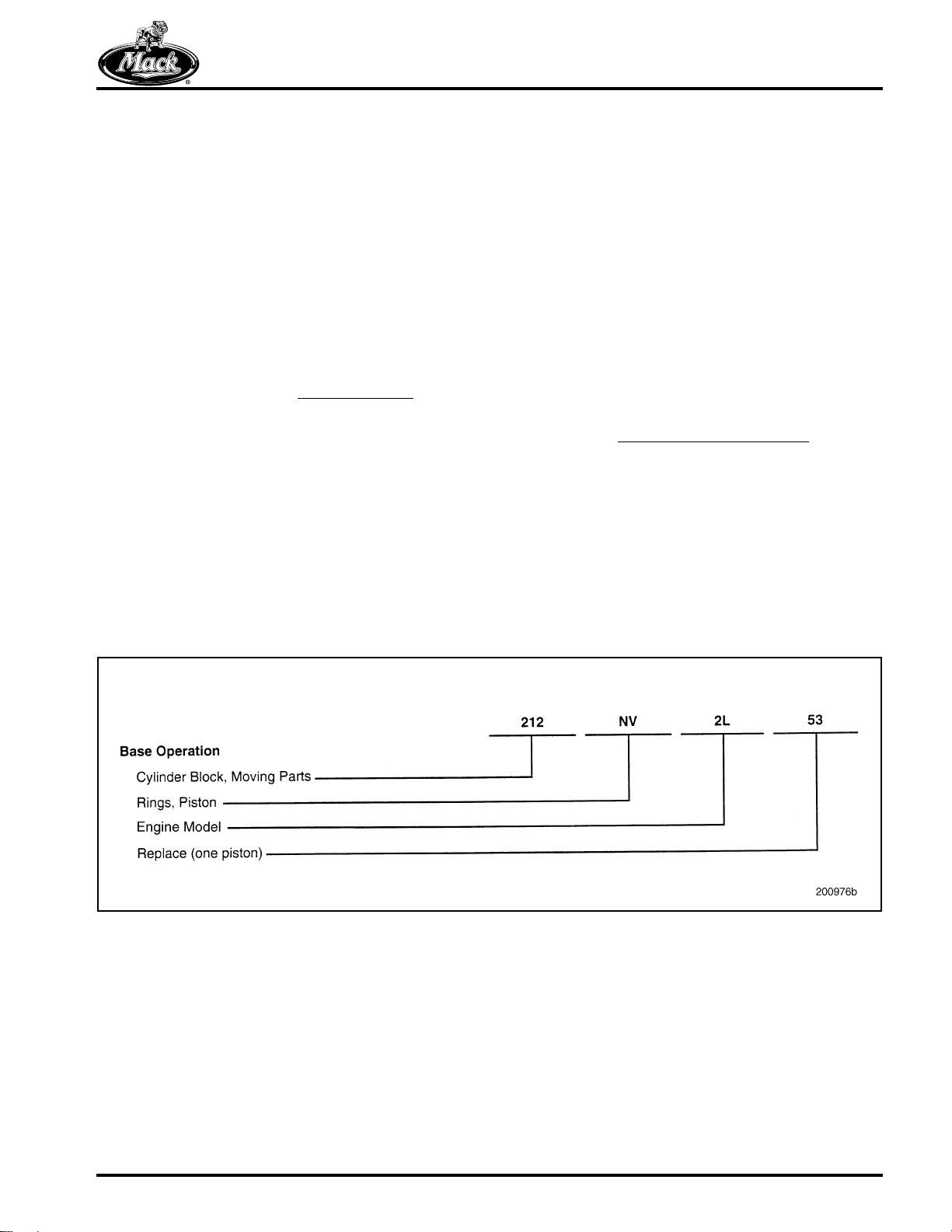
The system is based on a numerical code
first digit of which identifies the general
component grouping as listed here:
GROUP 000 — GENERAL DATA
GROUP 100 — CHASSIS
GROUP 200 — ENGINE
GROUP 300 — CLUTCH, TRANSMISSION,
TRANSFER CASE AND PTO
, the
GROUP 400 — STEERING, AXLES, WHEELS
AND TIRES, DRIVELINE
GROUP 500 — BRAKES, AUXILIARY SYSTEMS
GROUP 600 — CAB, TRUCK BODY
GROUP 700 — ELECTRICAL
The second two digits of the three-digit code are
used to identify the system, assembly or
subassembly, as appropriate, within each of the
groupings. The codes applicable to this
publication are shown at the beginning of each
procedure, as necessary, to guide you to specific
component information.
Additionally, a two-character alpha code
[NV] RINGS, PISTON) may be referenced with
each procedure. This alpha code, in combination
with the three-digit Group number, identifies the
specific assembly, sub-assembly or part, and
directly relates to the first five positions of the
operation code listed in MACK Service Labor
Time Standards.
(i.e.,
Example:
Numerical Code
Page 5
Page 17
INTRODUCTION
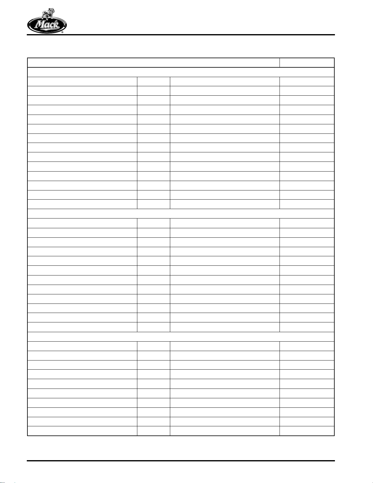
CONVERSION CHART
Conversion Units Multiply By:
Length Calculations
Inches (in) to Millimeters (mm) 25.40
Inches (in) to Centimeters (cm) 2.540
Feet (ft) to Centimeters (cm) 30.48
Feet (ft) to Meters (m) 0.3048
Yards (yd) to Centimeters (cm) 91.44
Yards (yd) to Meters (m) 0.9144
Miles to Kilometers (km) 1.609
Millimeters (mm) to Inches (in) 0.03937
Centimeters (cm) to Inches (in) 0.3937
Centimeters (cm) to Feet (ft) 0.0328
Centimeters (cm) to Yards (yd) 0.0109
Meters (m) to Feet (ft) 3.281
Meters (m) to Yards (yd) 1.094
Kilometers (km) to Miles 0.6214
Area Calculations
Square Inches (sq-in) to Square Millimeters (sq-mm) 645.2
Square Inches (sq-in) to Square Centimeters (sq-cm) 6.452
Square Feet (sq-ft) to Square Centimeters (sq-cm) 929.0
Square Feet (sq-ft) to Square Meters (sq-m) 0.0929
Square Yards (sq-yd) to Square Meters (sq-m) 0.8361
Square Miles (sq-miles) to Square Kilometers (sq-km) 2.590
Square Millimeters (sq-mm) to Square Inches (sq-in) 0.00155
Square Centimeters (sq-cm) to Square Inches (sq-in) 0.155
Square Centimeters (sq-cm) to Square Feet (sq-ft) 0.001076
Square Meters (sq-m) to Square Feet (sq-ft) 10.76
Square Meters (sq-m) to Square Yards (sq-yd) 1.196
Square Kilometers (sq-km) to Square Miles (sq-miles) 0.3861
Volume Calculations
Cubic Inches (cu-in) to Cubic Centimeters (cu-cm) 16.387
Cubic Inches (cu-in) to Liters (L) 0.01639
Quarts (qt) to Liters (L) 0.9464
Gallons (gal) to Liters (L) 3.7854
Cubic Yards (cu-yd) to Cubic Meters (cu-m) 0.7646
Cubic Centimeters (cu-cm) to Cubic Inches (cu-in) 0.06102
Liters (L) to Cubic Inches (cu-in) 61.024
Liters (L) to Quarts (qt) 1.0567
Liters (L) to Gallons (gal) 0.2642
Cubic Meters (cu-m) to Cubic Yards (cu-yd) 1.308
Page 6
Page 18
INTRODUCTION
Conversion Units Multiply By:
Weight Calculations
Ounces (oz) to Grams (g) 28.5714
Pounds (lb) to Kilograms (kg) 0.4536
Pounds (lb) to Short Tons (US tons) 0.0005
Pounds (lb) to Metric Tons (t) 0.00045
Short Tons (US tons) to Pounds (lb) 2000
Short Tons (US tons) to Kilograms (kg) 907.18486
Short Tons (US tons) to Metric Tons (t) 0.90718
Grams (g) to Ounces (oz) 0.035
Kilograms (kg) to Pounds (lb) 2.205
Kilograms (kg) to Short Tons (US tons) 0.001102
Kilograms (kg) to Metric Tons (t) 0.001
Metric Tons (t) to Pounds (lb) 2205
Metric Tons (t) to Short Tons (US tons) 1.1023
Metric Tons (t) to Kilograms (kg) 1000
Force Calculations
Ounces Force (ozf) to Newtons (N) 0.2780
Pounds Force (lbf) to Newtons (N) 4.448
Pounds Force (lbf) to Kilograms Force (kgf) 0.456
Kilograms Force (kgf) to Pounds Force (lbf) 2.2046
Kilograms Force (kgf) to Newtons (N) 9.807
Newtons (N) to Kilograms Force (kgf) 0.10196
Newtons (N) to Ounces Force (ozf) 3.597
Newtons (N) to Pounds Force (lbf) 0.2248
Torque Calculations
Pound Inches (lb-in) to Newton Meters (N•m) 0.11298
Pound Feet (lb-ft) to Newton Meters (N•m) 1.3558
Pound Feet (lb-ft) to Kilograms Force per Meter (kgfm) 0.13825
Newton Meters (N•m) to Pound Inches (lb-in) 8.851
Newton Meters (N•m) to Pound Feet (lb-ft) 0.7376
Newton Meters (N•m) to Kilograms Force per Meter (kgfm) 0.10197
Kilograms Force per Meter (kgfm) to Pound Feet (lb-ft) 7.233
Kilograms Force per Meter (kgfm) to Newton Meters (N•m) 9.807
Radiator Specific Heat Dissipation Calculations
British Thermal Unit per Hour (BTU/hr) to Kilowatt per Degree Celsius (kW/°C) 0.000293
Kilowatt per Degree Celsius (kW/°C) to British Thermal Unit per Hour (BTU/hr) 3414.43
Temperature Calculations
Degrees Fahrenheit (°F) to Degrees Celsius (°C) (°F − 32) x 0.556
Degrees Celsius (°C) to Degrees Fahrenheit (°F) (1.8 x °C) + 32
Page 7
Page 19

INTRODUCTION
Conversion Units Multiply By:
Pressure Calculations
Atmospheres (atm) to Bars (bar) 1.01325
Atmospheres (atm) to Kilopascals (kPa) 101.325
Bars (bar) to Atmospheres (atm) 0.98692
Bars (bar) to Kilopascals (kPa) 100
Bar (bar) to Pounds per Square Inch (psi) 14.5037
Inches of Mercury (in Hg) to Kilopascals (kPa) 3.377
Inches of Water (in H2O) to Kilopascals (kPa) 0.2491
Pounds per Square Inch (psi) to Kilopascals (kPa) 6.895
Pounds per Square Inch (psi) to Bar (bar) 0.06895
Kilopascals (kPa) to Atmospheres (atm) 0.00987
Kilopascals (kPa) to Inches of Mercury (in Hg) 0.29612
Kilopascals (kPa) to Inches of Water (in H2O) 4.01445
Kilopascals (kPa) to Pounds per Square Inch (psi) 0.145
Power Calculations
Horsepower (hp) to Kilowatts (kW) 0.74627
Kilowatts (kW) to Horsepower (hp) 1.34
Fuel Performance Calculations
Miles per Gallon (mile/gal) to Kilometers per Liter (km/L) 0.4251
Kilometers per Liter (km/L) to Miles per Gallon (mile/gal) 2.352
Velocity Calculations
Miles per Hour (mile/hr) to Kilometers per Hour (km/hr) 1.609
Kilometers per Hour (km/hr) to Miles per Hour (mile/hr) 0.6214
Volume Flow Calculations
Cubic Feet per Minute (cu-ft/min) to Liters per Minute (L/min) 28.32
Liters per Minute (L/min) to Cubic Feet per Minute (cu-ft/min) 0.03531
Page 8
Page 20
INTRODUCTION
ABOUT THE MACK MP8 ENGINE
[200 EA]
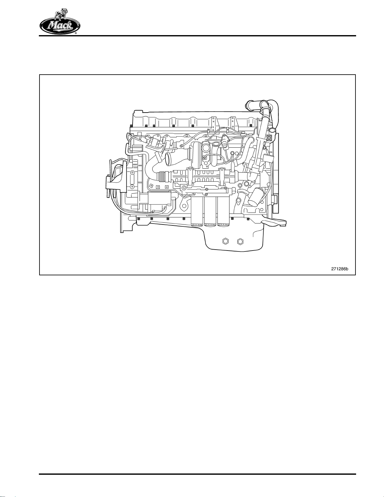
1
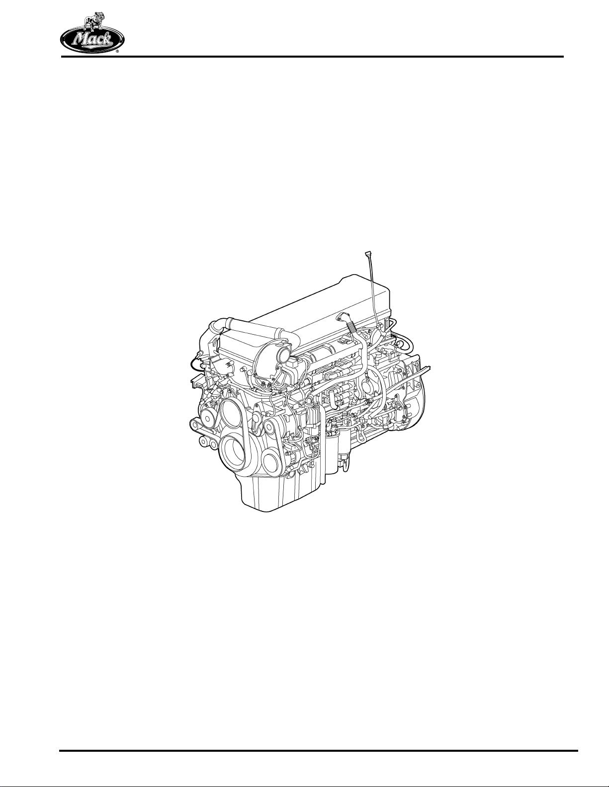
Figure 1 — MACK MP8 Engine — for Conventional Chassis
The MACK MP8 is a 13 liter (800 CID) engine
with electronic unit injectors, a cooled Exhaust
Gas Recirculation (EGR) system, a Diesel
Particulate Filter (DPF) system and the Holset
Variable Geometry Turbocharger (VGT). The
PowerLeash™ engine brake is optional. The
engine conforms to year 2007 Environmental
Protection Agency (EPA) requirements.
The MP8 EGR system features reduced
restriction plus enhanced efficiency and reliability.
Its venturi system is easy to service.
A DPF system requires elevated exhaust
temperatures. The system uses a diesel oxidation
catalyst, a diesel particulate filter and in-line
reheating of the exhaust gases. The DPF system
removes Particulate Matter (PM) from the
exhaust to conform to the 2007 EPA regulations.
The Holset VGT features fixed vanes with a
sliding nozzle ring. The nozzle position is infinitely
variable between open and closed. This design
reacts quickly to exhaust pressure and controls
inlet pressure more precisely. Reliability is
enhanced by having fewer moving parts. Its
actuator and bearing housing are water cooled
and engine oil lubricated for greater durability.
A wide range of the current transmission
offerings, including manual, automated manual
and automatic, can be teamed with the MP8.
Diagnostic help can be found in the Tech Tool. To
obtain the Tech Tool, contact your local MACK
dealer.
The engine weighs approximately 1160 kg
(2560 lb.) dry (with air compressor, without oil,
coolant, starter, fan, alternator and clutch). Its
design includes a one-piece cylinder head, a
single overhead camshaft, three rocker arms per
cylinder, unit injectors and no pushrods.
PowerLeash™ engine braking, requiring a fourth
rocker arm, is optional. Monosteel™ steel pistons
are made in one piece.
Page 9
Page 21
INTRODUCTION
Use of ether or similar types of starting aids in
MACK
strictly prohibited. This applies to engines
with or without the electric pre-heater option.
An explosion could occur. Failure to heed this
danger may result in severe personal injury or
death.
®
US07 emission compliant engines is
Fuel passes through two filters, one of which
separates water from the fuel. High-pressure fuel
in the unit injectors is created via the rocker arms
with roller followers in constant, direct contact
with the cams.
Replacing injectors requires a specific procedure,
and installation requires that the EECU be
programmed to recognize replacement injectors.
Cleaning injector bores requires a special tool.
Two optional fan drives are available: On/Off and
electronically actuated. The electronically
actuated viscous fan drive is precisely controlled
by the Engine Electronic Control Unit (EECU).
Timing gears mount on the rear of the MP8
improving the flow of cooling air around the front.
Special service instructions apply to the camshaft
position sensor. The mounting plate, idler and
camshaft gears are marked to facilitate proper
installation. The air compressor drive gear
meshes with the double idler instead of the
auxiliary idler as on the MP7 engine.
Another feature of the MP8 is the rear engine
power take-off (REPTO-ready) that is gear driven
through the timing gear train. An optional PTO
with drive gear, bearing and housing can be
added at the factory.
The rocker arm shaft is held in place by camshaft
bearing capscrews. There are special instructions
for installing the camshaft bearing caps and the
rocker arm shaft during service.
An engine compression brake option on the MP8
engine assists deceleration and braking. The
operation of the brake differs from earlier engine
models. Working in conjunction with the exhaust
cycle, the brake requires a camshaft with four
cams per cylinder, two rocker arms for the
exhaust valve, a bridge over the two exhaust
valves, an electronic control valve and a wiring
harness that includes the control valve. The
exhaust valves are adjusted with shims.
Unique colors and the appearance of the valve
cover, filters and logo labels distinguish the MP8
from other engines in the MACK line.
Preventive maintenance is important to get the
most from the MACK MP8 engine and to ensure
many years of reliable, trouble-free operation.
Refer to the current TS494 Maintenance and
Lubrication manual for schedules and
specifications.
Repair instructions in this manual deal with
removal, installation, disassembly, assembly,
setup and adjustments of MP8 components.
A stiffener plate fastens to the bottom of the
cylinder block to ensure block strength and
rigidity. The engine can be used with axle forward
or axle back vehicles by virtue of optional oil
pans. The engine fan is mounted high or low
depending on vehicle configuration.
The MP8 uses unit injectors. The unit injector
incorporates the pump, valve and injector. Its
internal solenoids permit fast, precise control of
fuel delivery into the cylinder. The unit injectors
are encased by the valve cover and not exposed
to the heat of exhaust system components.
Page 10
There are restrictions concerning the reuse of
certain fasteners. Refer to current specifications
bulletins and the SPECIFICATIONS section of
this manual for detailed information.
Page 22
INTRODUCTION
Service Precautions Summary
Following is a summary list of the DO and DON’T
issues applying to MP8 engine service.
1. DO NOT machine the cylinder head for
clean-up since this will change injector
depth, thereby affecting emissions. It will
also upset the ability to correctly adjust
timing gear backlash.
2. DO NOT grind the injector copper sleeves.
3. Install the crankshaft main bearing caps
according to marked assembly number.
4. Connecting rod caps MUST BE mated to
their respective connecting rods due to the
“fractured manufacturing” process used.
Also, the rod caps can be installed only one
way because of the difference in spacing
between screw holes at each side of the
cap.
5. DO NOT use the lifting eye on the flywheel
housing when tilting the engine/transmission
assembly to an angle greater than
15 degrees.
6. Cylinder head installation requires lowering
the head onto the gasket using the
alignment screws and washers at the sides
of the head and block. The head must be
pulled back to the mounting plate using
screws inserted through the plate. Pressed
bosses in the gasket keep the head from
making full contact with the gasket surface
and prevent damage to the elastomer
sealing rings as the head slides into
position.
Use of ether or similar types of starting aids in
MACK
strictly prohibited. This applies to engines
with or without the electric pre-heater option.
An explosion could occur. Failure to heed this
danger may result in severe personal injury or
death.
®
US07 emission compliant engines is
7. The MP8 engine uses a number of O-rings
for sealing various fluid joints and tubes. It is
essential that new O-rings of the correct
material be used whenever joints are
disassembled and reassembled.
Page 11
Page 23

NOTES
Page 12
Page 24

VISUAL IDENTIFICATION
VISUAL IDENTIFICATION
Page 13
Page 25
VISUAL IDENTIFICATION
MP8 ENGINE MODEL
IDENTIFICATION
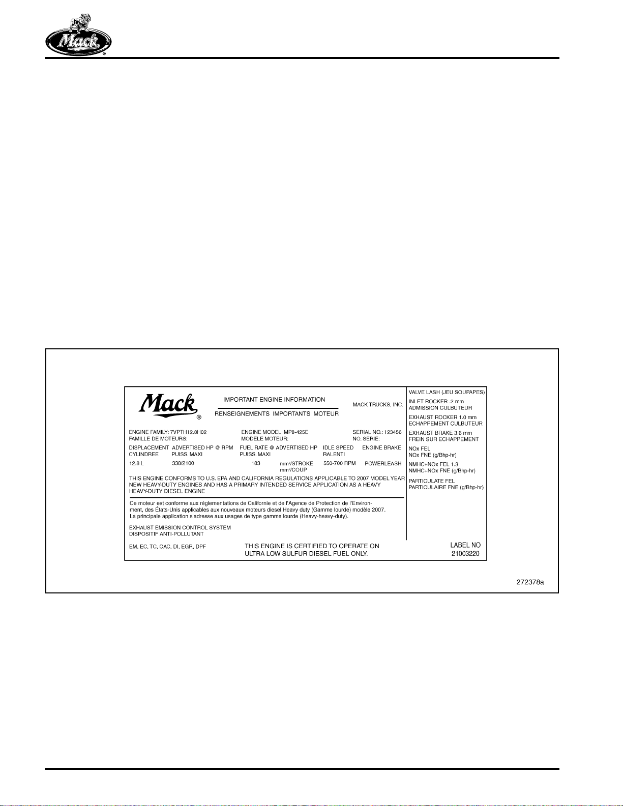
Engine Information Plate
The engine information plate is located on the top
of the cylinder head (valve) cover. This plate
includes information in English and French
concerning the following items.
앫 Engine family, model and serial number
앫 Displacement, horsepower, fuel rate, idle
speed and engine brake
앫 Emissions regulations to which the engine
conforms and other pertinent information
required by emissions regulations
앫 Valve lash settings for inlet, exhaust and
engine brake
앫 NOx, NMHC+NOx and particulate matter
emissions
앫 Exhaust emission control systems
A statement concerning the limitation on the fuel
to be used in the engine also appears.
Code letters under Exhaust Emission Control
Systems represent basic engine systems that
impact emissions. They are taken from the
following list.
앫 CAC — Charge Air Cooler
앫 DI — Direct Injection
앫 DPF — Diesel Particulate Filter
앫 EC — Engine Control
앫 EGR — Exhaust Gas Recirculation
앫 EM — Engine Modification
앫 TC — Turbocharger
2
Figure 2 — Engine Information Plate
Engine Serial Number Identification
In addition to the engine information plate on the
cylinder head cover, the engine is also identified
by the engine serial number stamped into the
cylinder block. This serial number is located on
the block left side at the front just below the inlet
manifold.
Page 14
Page 26

DESCRIPTION AND OPERATION
DESCRIPTION AND OPERATION
Page 15
Page 27
DESCRIPTION AND OPERATION
MACK MP8 US07 ENGINE DESIGN FEATURES
[200 EA]
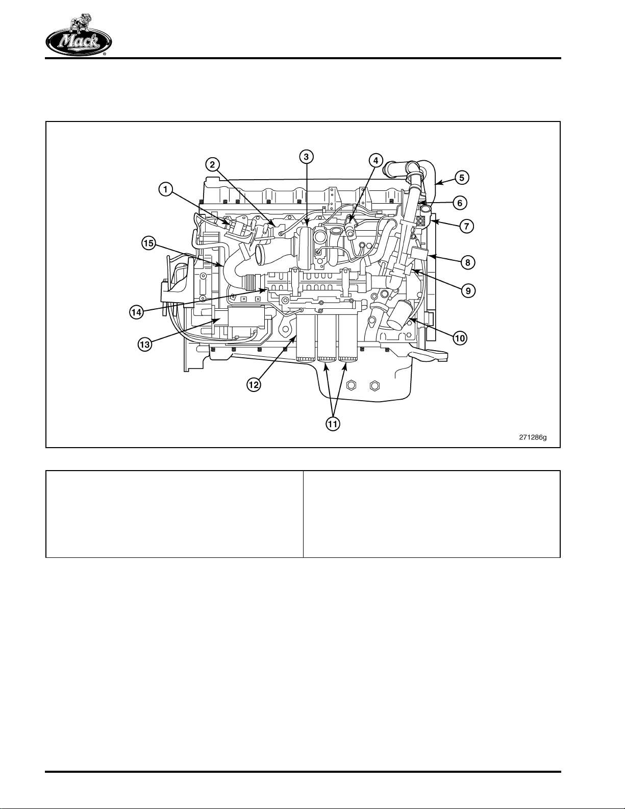
3
Figure 3 — MACK MP8 Engine — Conventional Chassis
1. EGR Valve
2. Aftertreatment Fuel Injector
3. Variable Geometry Turbocharger
4. Discharge Recirculation Valve
5. EGR Mixer
6. EGR Cooler Outlet Pipe
7. Thermostat Housing
To accommodate the low cab forward design, the
EGR system and the inlet manifold are configured
differently than for the conventional chassis. The
EGR mixer mounts at the front of the inlet
manifold on the conventional chassis, but near
the rear of the manifold on the low cab forward
design.
8. Differential Pressure Sensors
9. Venturi
10. Coolant Conditioner
11. Full Flow Oil Filters
12. Bypass Oil Filter
13. Starter
14. EGR Cooler
15. EGR Cooler Inlet Pipe
Page 16
Page 28
DESCRIPTION AND OPERATION
Engine Components
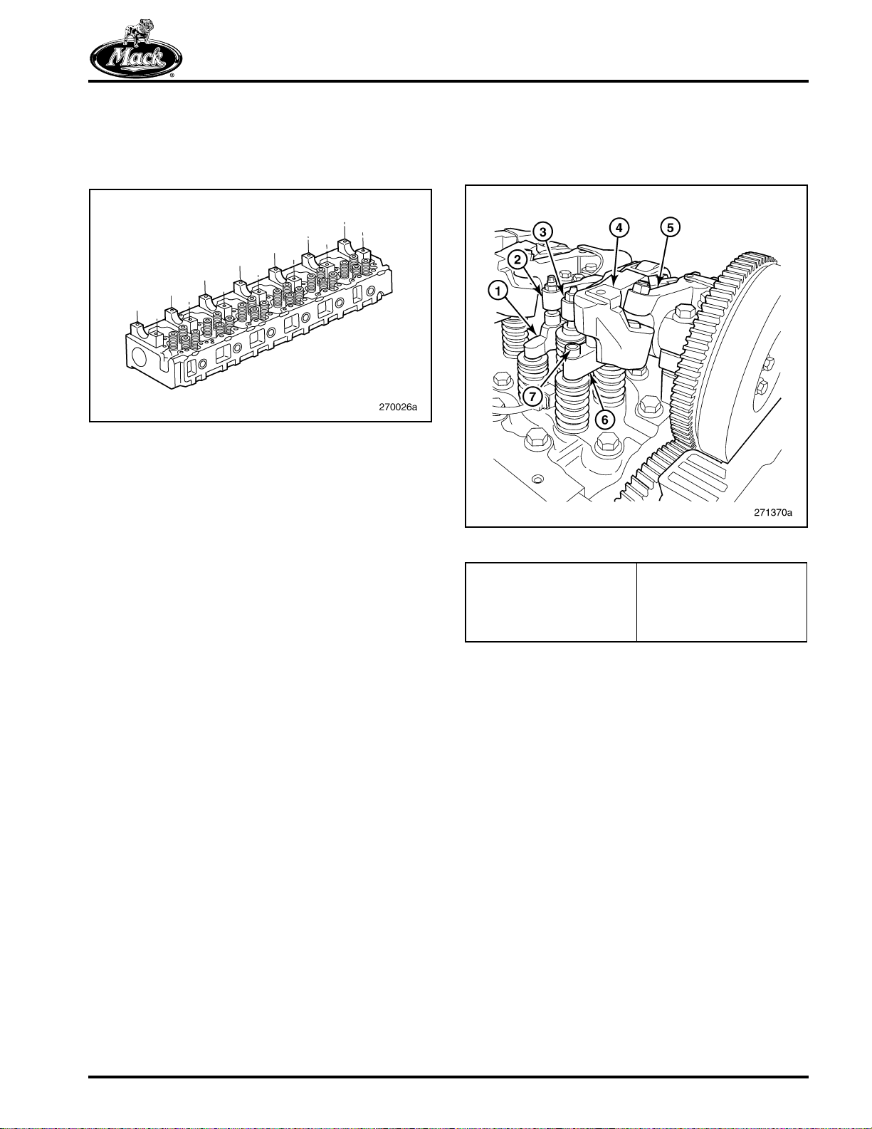
CYLINDER HEAD
4
Figure 4 — Cylinder Head with Valves and Camshaft
Supports
Main features of the cylinder head are:
앫 One-piece cast iron
PowerLeash™, the “brake” rocker arm works in
combination with the exhaust rocker arm to
precisely control the opening and closing of the
exhaust valves for engine braking.
5
앫 Integral thermostat housing
Separate chambers for exhaust and inlet at each
cylinder make this a “crossflow” design. The fuel
channel, drilled from front to rear, connects with
grooves machined around each injector opening.
A plug at the rear of the cylinder head seals this
channel.
CAMSHAFT AND VALVE TRAIN
The engine has an overhead camshaft and rocker
arm shaft in support of four valves per cylinder.
The camshaft rides on seven journals with a
bearing cap and support block (saddle) at each
point. The bearing inserts (shells), bearing caps
and support blocks are replaceable.
In standard configuration (with VGT exhaust
brake only), there are three cams for each
cylinder, including inlet, injection and exhaust.
There are four cams per cylinder in the optional
configuration (VGT exhaust brake plus
PowerLeash™) with the addition of a “brake” cam
at each cylinder.
The rocker arms are positioned on the shaft (front
to back) in the order of inlet, injector, exhaust and
brake, if so equipped. Both the inlet and exhaust
rocker arms each drive the valve pairs via a
pinless yoke (bridge). On engines equipped with
Figure 5 — Valve Train
1. Inlet Valve Yoke (Bridge)
2. Inlet Valve Rocker Arm
3. Injector Rocker Arm
4. Exhaust Valve Rocker
Arm
5. PowerLeash™ Rocker
Arm
6. Exhaust Valve Yoke
(Bridge)
7. Shim Retaining Screw
Exhaust valve yokes include a shim for
adjustment. Replaceable valve guides and seats
are made of alloyed cast iron and steel
respectively. All valve guides have oil seals.
Exhaust valves have double valve springs.
Rollers in the ends of the rocker arms contact the
cam shaft. The contacts with the yokes have ball
sockets for flexibility.
The camshaft is induction-hardened. Timing
marks for valve and injector adjustment are
located on the flange forward of the No. 1
camshaft journal. These marks are for adjusting
valve clearance. They do not apply to camshaft
timing.
Camshaft thrust washers are integral on the No. 7
journal bearing. Smooth rotation is ensured by
means of a vibration damper on the camshaft
gear. Teeth on the damper interact with the
camshaft position sensor for input to the EECU.
Page 17
Page 29
DESCRIPTION AND OPERATION
6
Figure 6 — Camshaft and Rocker Arms
1. Engine Brake Cam
2. Exhaust Cam
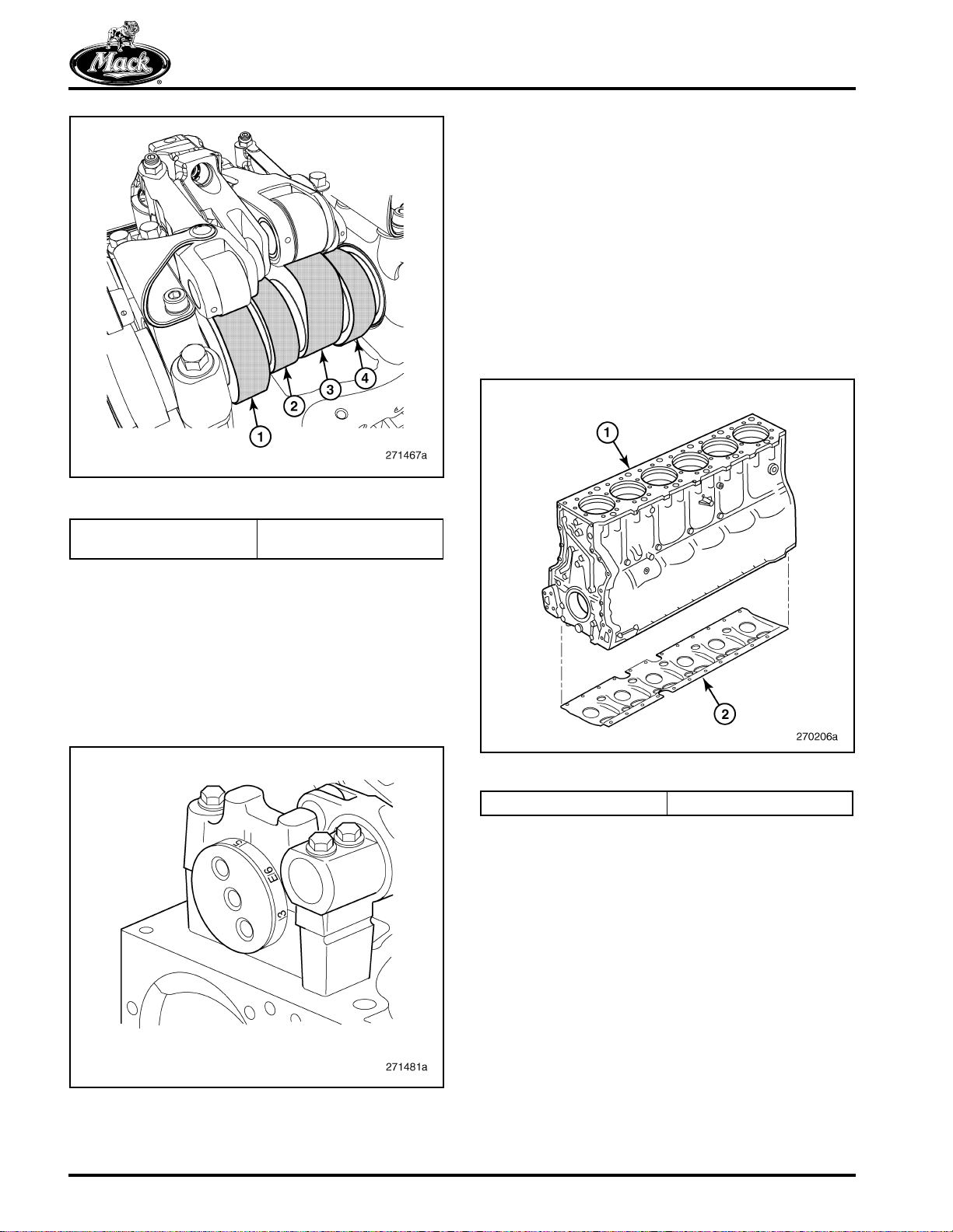
CYLINDER BLOCK
The cylinder block is made of cast iron. For
increased cylinder block rigidity and noise and
vibration reduction, a steel stiffener plate attaches
to the bottom.
The main and piston lubricating channels are
drilled longitudinally through the block. These are
plugged at the front of the block. The main
channel opens into a cast-in channel that
supplies oil to the timing gears. The piston
cooling channel is covered by the timing gear
cover.
8
3. Injector Cam
4. Inlet Cam
Timing marks on the camshaft provide for valve
and injector adjustment. PowerLeash™ includes
its own electronic control governed by driver's
choice through a switch near the steering wheel.
This control mounts on the cylinder head
between the No. 3 and No. 4 cylinder rocker
arms. The wiring harness includes additional wire
leads for PowerLeash™.
7
Figure 8 — Cylinder Block and Stiffener Plate
1. Cylinder Block 2. Block Stiffener Plate
Main bearing caps are made of nodular cast iron
machined together with the cylinder block. Cast
alignment slots in the block and tabs on the caps
ensure proper alignment at installation. Each cap
is marked with its location beginning with No. 1 at
the front. Cap Nos. 4 and 7 are unique and are
not numbered.
The block includes cylinder liners that contact the
coolant directly (wet liners). The casting shape
follows the contours of the cylinders to increase
rigidity and reduce noise.
Figure 7 — MP8 Engine Timing Marks — Camshaft Front
Page 18
End
Page 30
DESCRIPTION AND OPERATION
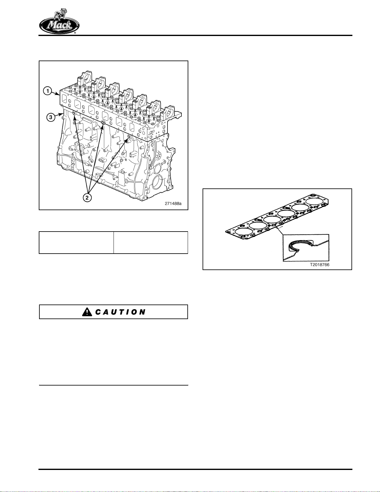
Head to Block Alignment
9
Figure 9 — Head to Block Alignment Screws and
Washers
CYLINDER HEAD GASKET
The cylinder head gasket is made of one piece of
sheet steel with vulcanized elastomer seals on oil
and coolant conduits. The design of the engine
and head gasket requires a unique procedure for
installation of the cylinder head.
The screws and washers at the side guide the
head into side-to-side alignment as it is laid on
the gasket and block. Screws passed through the
timing gear plate into the head pull the head into
alignment fore and aft. Small, stamped bosses on
the gasket hold the head clear of the seals and
allow it to glide accurately into position against
the plate during installation. Tightening the head
bolts flattens the bosses on the gasket. For this
reason, a new head gasket must be installed
whenever the head is removed.
10
1. Cylinder Head
2. Alignment Screws and
Washers
3. Cylinder Block
Three screws and washers installed at the side
(two in the block and one in the head) align the
head from side to side at assembly. Fore and aft,
the head is aligned by contact with the timing
gear plate.
The head is aligned with the timing gear plate by
screws passed through the plate into the head
and tightened securely. It is extremely important
to remove these screws before attempting to
remove the cylinder head from the block. Failure
to heed this caution may result in severe damage
to the timing gear plate and other engine
components.
Figure 10 — Cylinder Head Gasket
Page 19
Page 31

DESCRIPTION AND OPERATION
CYLINDER LINERS
The cylinder block uses replaceable wet cylinder
sleeves. The lower end of each sleeve is sealed
against the block with three elastomer rings. The
upper end is sealed with a ring of EPDM
elastomer situated directly under the sleeve
collar. This design cools the upper section of the
sleeve better because the area of coolant
circulation is larger.
The lower seals are fitted in grooves in the
cylinder block. The bottom seal is of a different
material and fluorescent violet in color to
distinguish it from the intermediate seals.
11
OIL PAN
The oil pan is plastic or steel with a threaded plug
for draining. The plastic pan has a groove in the
mounting flange which accepts a molded
elastomer gasket for a seal. The steel pan is
sealed with a gasket on the oil pan flange.
Twenty-two spring-loaded screws clamp the pan
to the block.
12
Figure 11 — Cylinder Liner and Seals
1. Upper O-Ring — EPDM
(Black)
2. Middle Sealing Rings —
EPDM (Black)
Figure 12 — Oil Pan and Stiffener Plate
1. Block Stiffener Plate 2. Oil Pan with Gasket
The oil pan includes an oil level/temperature
sensor with connector. The filler tube and dipstick
mounting ports are also components of the oil
pan.
3. Lower Sealing Ring —
Viton (Purple)
Oil pans with the sump at the front or at the rear
are available to accommodate axle forward or
axle back chassis.
Page 20
Page 32

DESCRIPTION AND OPERATION
CRANKSHAFT
The crankshaft is drop forged steel and induction
hardened. It has seven journals with replaceable
bearings. Five oversized replacement bearing
options are available to accommodate crankshaft
regrinding.
The rear main cap (No. 7) includes an attaching
point for the lube pump. Thrust washers to control
axial movement straddle the central journal (cap
No. 4). The remaining caps (Nos. 1–3, 5 and 6)
are numbered to facilitate correct assembly.
13
Figure 13 — Crankshaft, Bearings, Thrust Washers and Cap Alignment Tabs
1. Alignment Tab, Block
2. Alignment Tab, Cap
A Teflon® seal bearing directly on the crankshaft
flange is used at the front of the crankshaft. The
front seal has an outer felt ring which serves as a
dust cover. At the rear of the crankshaft is another
seal that bears directly on the machined surface
of the crankshaft gear. Additionally at the rear,
there is a groove in the rear crankshaft flange for
an O-ring which forms a seal between the flange
and the gear.
3. Thrust Washers
4. Upper and Lower Bearings
Whenever the lower main bearings caps are
installed in the engine block, pay special attention
to ensure the lower main bearing cap is installed
in the same location of the engine block as
removed. Also, ensure that the aligning mark on
the bearing cap aligns with the mark on the
engine block.
Page 21
Page 33

DESCRIPTION AND OPERATION
PISTONS AND CONNECTING RODS
14
Figure 14 — Piston and Connecting Rod
1. Piston Ring Set
2. Wrist Pin Snap Ring
3. Piston
4. Piston Cooling Nozzle
5. Assembly Matching Marks
Connecting rods are forged steel and are used in
combination with one-piece Monosteel™ steel
pistons. The bearing caps are attached with four
M12 capscrews spaced to prevent misalignment.
The rods and caps are made by a “fracture”
process that requires a cap be assembled with its
original rod. Never attempt to use mismatched
rods and caps.
The piston is fitted with three rings. In the top
groove is a compression ring with a “keystone”
cross section. In the second groove, the
compression ring has a rectangular cross
section. In the third groove is a spring-loaded oil
scraper ring.
6. Connecting Rod Bolts
7. Connecting Rod Bearing Cap
8. Upper and Lower Connecting Rod Bearings
9. Connecting Rod
10. Wrist Pin
15
Page 22
Figure 15 — Piston Cooling
1. Piston Cooling Nozzle
2. Control Valve
3. Opening Valve
Page 34

DESCRIPTION AND OPERATION
Oil flow for the piston cooling system is controlled
by two valves. The opening valve supplies oil and
the control valve balances the oil flow to the
piston cooling channel. The piston cooling nozzle
is aligned so that the oil jet hits the underside of
the piston crown.
TIMING GEARS
The timing gears are located at the rear of the
engine. Backing up the gears is a plate: a 6 mm
(1/4 inch) thick steel sheet attached to the
cylinder block.
The advantages of this configuration are more
precise timing, fewer components and lower
noise levels.
16
The power steering/fuel pump gear, the air
compressor gear and the PTO gear are not timing
gears. The pump and compressor gears fasten to
their respective components. The pump gear is
driven by the auxiliary idler gear. The compressor
gear is driven by the double idler gear.
The double idler drives the adjustable idler and
the gear used to drive the power take-off, if so
equipped. This is part of the “REPTO-Ready”
feature. A PTO unit with drive gear is substituted
for a cover on the flywheel housing.
The camshaft gear fastens to the hub on the end
of the shaft. A vibration damper also attaches to
the hub outboard of the gear. Teeth on the
damper actuate the camshaft position sensor.
The gear is driven via the adjustable idler.
Figure 16 — Timing Gears and Plate
1. Crankshaft Gear
2. Double Idler Gear
3. Adjustable Idler Gear
4. Camshaft Gear and
Damper
5. Auxiliary Idler Gear
6. Power Steering/Fuel
Pump Gear
7. Air Compressor Gear
8. Oil Pump Gear
9. Power Take-Off Gear
(Optional)
10. Timing Gear Plate
Page 23
Page 35

DESCRIPTION AND OPERATION
DRIVE BELTS
This engine can be configured to accommodate
either the conventional chassis or the low cab
forward (LCF) design. Depending on the vehicle,
the fan location may be high or low on the fan
bracket.
Two poly-V belts drive the front engine
accessories. The outer, primary belt (10 or
12 ribs) drives the coolant pump and fan hub from
a pulley on the crankshaft flange nested in the
vibration damper. The inner, secondary belt (six
ribs), driven by the crankshaft vibration damper,
drives the alternator and refrigerant compressor.
17
Each belt uses an automatic tensioner. In the
high position, Figure 17, there are two idler
pulleys in the primary loop: one between the
coolant pump pulley and the tension idler; the
other between the crankshaft pulley and the fan
hub.
18
Figure 17 — Primary and Secondary Drive Belts —
1. EGR Cooler Outlet Pipe
2. Fan Drive
3. EGR Mixer
4. Belt Tensioner
(Alternator/Refrigerant
Compressor Belt)
5. Alternator (Pad Mount)
Conventional Chassis
6. Refrigerant Compressor
(Pad Mount)
7. Belt Tensioner (Fan
Drive/Water Pump Belt)
8. Water Pump
9. Venturi
10. Differential Pressure
Sensors
Figure 18 — Primary and Secondary Drive Belts — LCF
1. EGR Cooler Outlet Pipe
2. Fan Drive
3. EGR Mixer
4. Belt Tensioner
(Alternator/Refrigerant
Compressor Belt)
5. Alternator (Pad Mount)
Chassis
6. Refrigerant Compressor
(Pad Mount)
7. Belt Tensioner (Fan
Drive/Water Pump Belt)
8. Water Pump
9. Venturi
10. Differential Pressure
Sensors
In the low position, Figure 18, the idler between
the damper and fan pulleys is omitted.
Page 24
Page 36

DESCRIPTION AND OPERATION
Lubrication System
A gear-type pump at the rear of the engine,
driven by the crankshaft gear, draws lubricant
from the oil pan and supplies the system. Oil
flows from the pump through the distribution
housing to the filters, to a gallery at the right side
of the engine serving the crankshaft journals, to a
gallery at the left side serving piston lubrication
OIL PUMP
19
and cooling, to the cylinder head and rocker shaft
duct (valve rocker and camshaft) and back to the
oil pan. The system includes crankcase
ventilation.
Two full-flow filters and a by-pass filter maintain
clean lubricant. A sensor in the oil pan monitors
fluid level. There is an oil cooler immersed in
engine coolant inside the coolant duct cover.
Figure 19 — Lubrication System Diagram
A strainer and pickup tube lead the lubricant into
the pump. For the axle forward oil pan, the
strainer is mounted on a short tube held in place
by a bracket attached to the distribution housing.
For the axle back model, a long tube without the
bracket is supplied.
Page 25
Page 37

DESCRIPTION AND OPERATION
OIL FLOW CONTROL AND FILTRATION
20
Figure 20 — Lubrication System Flow Diagram
1. Strainer
2. Pickup Tube
3. Oil Pump
4. Pressure Pipe
5. Oil Cooler
6. Filter Housing
7. Full-Flow Filters
8. Main Lubrication Gallery
9. CCV Separator
10. Exhaust Brake Oil Control Valve
11. Air Compressor
There are three filters, one by-pass and two
full-flow, attached to a housing mounted at the
lower right side of the engine. Oil flow through the
filters and the lubrication system is controlled by
six valves, including:
앫 Reducing Valve
앫 Safety Valve
앫 Oil Cooler Thermostat Valve
앫 Overflow Valve, Full-Flow Filter
앫 Opening Valve, Piston Cooling
12. Turbocharger
13. By-Pass Filter
14. Piston Cooling Nozzles
15. EGR Valve
A. Reducing Valve
B. Safety Valve
C. Oil Cooler Thermostat Valve
D. Overflow Valve, Full-Flow Filter
E. Opening Valve, Piston Cooling
F. Control Valve, Piston Cooling
The reducing valve maintains constant system oil
pressure. The safety valve prevents excessive
pressure during periods of high viscosity. The oil
cooler thermostat valve prevents oil from entering
the cooler until it warms to the set point. The
overflow valve allows oil to by-pass the filter if it
becomes clogged. The opening valve prevents oil
from moving to the piston cooling outlets until the
system reaches the set pressure. The control
valve regulates the oil flow to the piston cooling
channels.
앫 Control Valve, Piston Cooling
Page 26
Page 38

DESCRIPTION AND OPERATION
Crankcase Ventilation
Lubricant becomes a mist in many areas of the
engine as the result of the motion of the parts
(e.g., rocker arms, pistons, crankshaft, camshaft
and rocker shaft). The mist rides the drafts of air
and other gases that circulate in the open spaces
in the engine. To prevent pressure buildup, the
open spaces are ducted through a pipe that
opens to the atmosphere near the bottom of the
engine.
The crankcase ventilation (CCV) system
separates the oily mist from the gases by
centrifugal force. The oil returns to the oil pan.
The remainder escapes to the atmosphere.
21
Figure 21 — Crankcase Ventilation System Separator
1. Seal Ring
2. Separator Inlet Hose
3. Separator Vent Tube
4. Vent Tube Bracket
A turbine in the CCV separator, driven by a small
stream of oil striking its fins, spins at high speed.
The mixture of gases and oily mist trapped in the
valve cover and the timing gear cover drains onto
the top of the center of the turbine and runs down
onto several discs rotating with the turbine.
Separation occurs as the mixture, flung outward
by the turbine, strikes the walls of the CCV. The
droplets of mist coalesce into a liquid and drain
back into the oil pan along with the oil that drives
the turbine. The gases are free to leave via an
open port.
5. Separator Housing
6. Housing Seal
7. Pressure Regulator
The open port connects to a tube leading to the
bottom of the engine where road draft draws the
gases into the atmosphere.
Page 27
Page 39

Fuel System
22
DESCRIPTION AND OPERATION
Figure 22 — Fuel System Diagram
1. Fuel Pump
2. Fuel Tank and Inlet Tube
3. EECU Cooler
4. Fuel Filter Housing
5. Fuel Pre-Filter
6. Water Cup
7. Secondary (Main) Filter
8. Fuel Gallery
9. Unit Injector
10. Pressure Regulator Valve
11. Pump Safety Valve (Pressure Regulator)
12. One-Way Valve
13. Hand Pump Handle
14. Water Level Sensor
The fuel pump attaches with the power steering
pump to the flywheel housing at the rear left side.
It turns on the same shaft as the power steering
pump. The common drive gear meshes with the
auxiliary idler driven by the crankshaft gear. At
600 rpm, the pump delivers a minimum 100 kPa
(14.5 psi), and at 1200 rpm, 300 kPa (43.5 psi).
At 400–550 kPa (58–80 psi), the gallery regulator
valve opens to control fuel gallery pressure.
15. Water Discharge Control Switch (Instrument Panel)
16. Electrical Water Drain Valve
17. Automatic Air Bleed Valve (closes when filter removed)
18. Service Port (Pressure Gauge)
19. Supply Pressure Sensor
20. Fuel Heater (Optional)
21. Service Shutoff Valve (closes when filter removed)
22. One-Way Valve (Hand Priming)
23. Automatic Air Bleed Valve
24. Fuel Tank Breather
25. AFI Shut-Off Valve
26. To Aftertreatment Fuel Injector (AFI)
27. Deaeration Valve
Page 28
Page 40

DESCRIPTION AND OPERATION
Fuel is drawn by the suction side of the fuel pump
from the fuel tank into the ECU cooling plate and
enters the fuel filter housing. Fuel passes by the
one-way check valve which prevents the bleeding
of fuel back to the fuel tank and into the primary
fuel filter. The fuel becomes filtered by passing
through the filter media from the outside to the
center of the primary fuel filter. The fuel leaves
the primary filter and passes by a one-way valve
located in the threaded nipple of the primary filter.
The fuel flows from the filter housing to the
suction side of the fuel pump through an external
fuel line. Fuel becomes pressurized after leaving
the fuel pump and flows back to the filter housing
to enter the secondary filter. The fuel becomes
filtered by passing through the filter media from
the outside to the center of the secondary filter.
The fuel leaves the secondary filter and passes
by an automatic air bleed valve which is located in
the threaded nipple for the secondary filter. Fuel
passes by the fuel pressure sensor and then exits
the filter housing to enter the rear of the cylinder
head through an external fuel line. After fuel
enters the cylinder head, it passes through the
fuel gallery of the cylinder head to continuously
deliver fuel to all six unit injectors. Fuel leaves the
cylinder head after passing by the fuel pressure
regulator located at the left front corner of the
cylinder head. Fuel is routed back from the
cylinder head to the filter housing through an
external fuel line to deliver some return fuel back
into the suction side which goes to the fuel pump.
Any excessive fuel not consumed is bled off
through the de-aeration valve and then, directed
back to the fuel tank.
FUEL FILTRATION
Primary and secondary filter elements attach to
the underside of the filter valve housing. The
housing, located at the front lower left side of the
cylinder block, has an integral hand-priming
pump for bleeding the system. The 30 micron
pre-filter (primary filter) also separates water from
the fuel. Water collects in a cup on the bottom of
the pre-filter. There is a sensor to keep track of
the water and signal the EECU.
A one-way check valve located in the filter
housing prevents fuel from draining back to the
fuel tank when the engine is shut down. Also
included in the fuel filter housing is the fuel
pressure sensor just above the secondary filter.
앫 The collected water can be dumped only
while the engine is not running, the key is in
the ON position and the parking brake is set.
앫 Some trucks are built with a remote mounted
fuel water separator. In this case, the fuel is
drawn through the remote mounted filter
before it reaches the ECU cooler plate. On
the filter base, the mounting location for the
standard primary filter is blocked off with a
plate.
Page 29
Page 41

UNIT INJECTORS
23
DESCRIPTION AND OPERATION
1. Injector Yoke
2. Copper Sleeve
3. O-Ring
4. Fuel Gallery
5. O-Ring
6. O-Ring
7. Pressure Relief Valve
Figure 23 — Unit Injector Diagram
8. Solenoid Coil
9. Solenoid Coil
10. Injector Valve
11. Injector Piston
12. Injector Nozzle
13. Washer
Page 30
Page 42

DESCRIPTION AND OPERATION
This engine uses double solenoid unit injectors.
Unlike systems that require separate components
for delivering, pressurizing and injecting, this unit
injector combines these functions. These
injectors precisely control the fuel delivery
because of the two solenoids. The solenoids,
pump and nozzle are in a single body in close
proximity to each other.
The injector is set in a pressurized fuel gallery
where the fuel temperature is constant. Uniform
fuel temperature means uniform quantity in each
injection which means uniform power output from
each cylinder.
The fuel pump pressurizes the gallery so that fuel
rushes into each injector when it opens. Gallery
pressure is regulated by a valve that delivers
excess fuel back to the tank.
Copper sleeves, acting as coolant jackets, line
the bottoms of the injector bores. Engine coolant
circulates around these sleeves aiding the
process of controlling injection temperature.
There are four phases to the injector cycle of
operation. These include:
앫 Fill phase
앫 Spill phase
앫 Injection phase
앫 Pressure drop phase
24
Figure 24 — Unit Injector — Fill and Spill Phases
1. Pump Plunger
2. Fuel Gallery
Fill phase (A): During the filling phase, the pump
plunger is on its way up, the camshaft lobe is
passing its highest point and the rocker arm is on
its way toward the camshaft base circle. The fuel
valve is open, allowing fuel to flow into the unit
injector from the lower fuel gallery. Fuel flows into
the cylinder head and the unit injector pump
cylinder. Filling continues until the pump plunger
reaches its upper position.
3. Injector Nozzle
Spill phase (B): The spill phase begins when the
camshaft lobe forces the rocker arm to push the
pump plunger down. The fuel can now flow
through the fuel valve, through the holes in the
unit injector and out through the fuel gallery. The
spill phase continues as long as the fuel valve is
open.
Page 31
Page 43

DESCRIPTION AND OPERATION
25
Figure 25 — Unit Injector — Injection and Pressure Drop Phases
1. Pump Plunger
2. Fuel Gallery
Injection phase (C): The injection phase begins
when the fuel valve closes. The camshaft lobe
and rocker arm continue to press down on the
pump plunger and injection occurs as the path
through the fuel valve closes. The injection phase
continues as long as the fuel valve is closed.
Pressure drop phase (D): The injection phase
ends when the fuel valve opens and pressure in
the unit injector drops below the nozzle opening
pressure. The fuel flows through the open fuel
valve, through the unit injector holes and out
through the fuel gallery. Note that the fuel valve
position (closed or open) determines when the
injection phase begins and ends. The time during
which the fuel valve is closed determines the
amount of fuel injected at each pump stroke.
Unit injectors are categorized and coded with
regard to tolerances. Whenever a unit injector is
replaced, the replacement injector MUST be
programmed for the cylinder in which it is
installed. This is done by programming EECU
parameters using the VCADS pro or the Premium
Tech Tool (PTT) to set Injector Trim parameters
with the trim codes marked on the injectors.
3. Injector Nozzle
The dimension by which the injector nozzle
extends from the head is critical. This means that
machining the head in any way that changes this
nozzle extension is not permitted.
26
Page 32
Figure 26 — Injector Coding
1. Serial No. 2. Unit Calibration No.
Page 44

DESCRIPTION AND OPERATION
PowerLeash™ Engine Brake
The engine can be equipped with a
PowerLeash™ engine brake system to assist in
slowing the vehicle when necessary. The system
includes the:
앫 Wiring harness
앫 Camshaft
앫 Oil control valve
앫 Exhaust rocker arms
앫 Engine brake rocker arms
앫 Exhaust valve yokes (bridges)
There is a separate cam on the camshaft at each
cylinder for the engine brake rocker arm. The
lobes on this cam are timed to coordinate with the
lobes on the exhaust valve cam.
The exhaust rocker arm operates normally. When
engaged, the engine brake rocker arm also
operates the exhaust rocker arm. It causes the
valve to open in a strategy to decrease cylinder
power output. Engine power is reduced assisting
the brakes in slowing the vehicle.
The engine brake rocker arms are equipped with
a blade spring which keeps the rollers in contact
with the cams.
27
PowerLeash™ operation depends on all of the
following conditions which must exist
simultaneously.
앫 Accelerator pedal released
앫 Engine speed above 1100 rpm
앫 Clutch pedal released
앫 Road speed above 5 km/h (3.1 mph)
앫 ABS inactive
앫 Transmission in gear
앫 Oil temperature above 55°C (131°F)
앫 Charge air pressure above 50 kPa (7.25 psi)
On the cylinder head, the oil control valve
connects the oil passages in the head and rocker
shaft. The oil pump produces constant pressure
at this junction. While the accelerator pedal is
depressed, the control valve reduces the oil
pressure in the rocker shaft to a minimum
100 kPa (14.5 psi).
When the accelerator pedal is released (and the
PowerLeash™ switch is ON), the solenoid opens
allowing some oil to escape through a small port.
Reduced spring pressure moves the piston,
opens the passage to the rocker shaft and
increases the oil pressure. The system opens the
exhaust valve during induction and again
immediately before TDC on the compression
stroke.
Figure 27 — PowerLeash™ Oil Control Valve — Location
1. Tie Wraps
2. Electrical Connector
3. Attaching Screws
4. Solenoid
5. Tube — Valve to Shaft
The engine slows because the extra volume
under compression takes more power to
compress, and escaping pressure in the
combustion stroke reduces the power output. A
switch on the instrument panel allows the driver
to engage or disengage PowerLeash™.
If the ABS system becomes active, it
automatically disables PowerLeash™. If the oil
temperature goes below 55°C (131°F),
PowerLeash™ cannot be activated. A warning
lamp on the instrument panel flashes if the driver
attempts to activate it under this condition.
A port located in the front of the cylinder head
near the thermostat housing allows access to the
oil passageway. The plug can be removed and a
gauge and hose assembly inserted for use during
diagnostic procedures.
Page 33
Page 45

DESCRIPTION AND OPERATION
System Oil Pressure
Engine
Speed/RPM Temperature Pressure
600 90–110°C
(195–230°F)
>1100 90–110°C
(195–230°F)
>1100 Cold Engine 650 kPa
Rocker Shaft
Engine Brake
Active 900–2300 220 kPa
Inactive — 80–120 kPa
Engine
Speed/RPM Oil Pressure
>250 kPa
(>36 psi)
300–550 kPa
(44–80 psi)
(95 psi)
(32 psi)
(12–17 psi)
Exhaust Gas Recirculation System
28
Nitrous oxide (NOx) emission levels increase with
combustion temperature. The primary function of
the Exhaust Gas Recirculation (EGR) system is
to cool exhaust gas and send it back to the
combustion chamber to lower the combustion
temperature thereby to reduce NOx emissions.
EGR systems are configured differently for the
LCF and conventional chassis engines. The
mixer, where the recirculated exhaust joins the
inlet air, mounts at the front of the inlet manifold
for the conventional chassis, but for the LCF
chassis, it is located near the rear of the manifold.
This requires differences in the ducting from the
EGR cooler to the mixer.
EGR VALVE
This engine uses the EGR valve to recirculate
exhaust gases. Engine oil operates the EGR
valve. The EECU determines the desirable valve
opening based on inputs from a number of
sensors and commands the EGR valve solenoid
to open or close the valve.
Figure 28 — EGR Components — Conventional Chassis
1. EGR Valve
2. EGR Cooler Inlet Pipe
3. EGR Cooler
4. Venturi
Engine
5. Differential Pressure
Sensors
6. EGR Cooler Outlet Pipe
7. EGR Mixer
Corrosion occurs in the inlet manifold if exhaust
gas condenses there. This can produce both
internal and external damage. To eliminate
corrosion, the EECU compares engine RPM,
torque load, ambient temperature, inlet manifold
temperature and EGR demand to calculate the
dew point in the inlet manifold. It then adjusts the
EGR opening to stay above the dew point.
Additionally, surfaces within the inlet manifold and
the mixing chamber are treated to resist
corrosion.
The EGR valve attaches to the rear section of the
exhaust manifold for reliable response and
turbocharger efficiency. This location also
protects the EGR cooler from harmful high
pressure exhaust pulses that occur during engine
braking.
Page 34
Page 46

DESCRIPTION AND OPERATION
EGR VALVE FUNCTION
When the EGR valve is open, exhaust gas
recirculates into the combustion chamber. The
valve is normally closed when engine coolant
temperature is below 65°C (149°F) unless the
EECU commands the valve open during
automatic cooler cleaning mode. When coolant
temperature exceeds 65°C (149°F), engine load
exceeds 50%, and RPM exceeds 1200, the
EECU opens the EGR valve to approximately
90% of its range.
At idle, the EECU monitors exhaust temperature
every three minutes. If it exceeds 98°C (208°F),
the valve opens to approximately 14% of its
range. Otherwise, it remains closed.
EGR COOLER INLET PIPE
29
EGR COOLER
The EGR valve is connected to the EGR cooler
by the cooler inlet pipe. Using engine coolant, the
EGR cooler lowers the temperature of the gas
coming from the EGR valve. The cooler contains
a series of vanes that increase cooling efficiency
by swirling the hot gas before it enters the mixer.
EGR VENTURI SYSTEM
On leaving the EGR cooler, the gas flows through
a venturi equipped with two pressure sensors.
The venturi changes the speed and density of the
flow. The sensors report the pressure difference
to the EECU.
EGR COOLER OUTLET PIPE
The EGR cooler outlet pipe carries the exhaust
gas from the venturi to the mixer. Relatively short,
the tube passes over the valve cover, behind and
into the mixer at the front end of the inlet manifold
on the conventional chassis engine.
Figure 29 — EGR Valve and Cooler Inlet Pipe
1. EGR Valve
2. Cooler Inlet Pipe
3. Clamps
4. EGR Cooler
5. Electrical Connector
6. Oil Supply Line
The cooler inlet pipe conducts the exhaust from
the EGR valve to the EGR cooler. The cooler
lowers the exhaust stream temperature before it
reenters the combustion chamber.
Relatively much longer on the LCF, the tube
passes from the venturi around the front of the
valve cover and reaches back to the mixer at the
rear end of the inlet manifold.
A temperature sensor monitors exhaust
temperature sending the data to the EECU.
Excessively high temperature, or abnormally high
temperature for more than 30 minutes during an
hour, causes the EECU to limit engine power to
prevent engine damage.
EGR MIXER
The EGR mixer is the meeting point for cooled,
recirculating exhaust gas and outside air from the
CAC. From here, the combined gases pass into
the inlet manifold and on to the combustion
chamber.
INLET AIR HEATER
The optional inlet air heater mounts between the
mixer and the inlet manifold. It is activated when
the operator turns the key to the preheater
position and the engine coolant temperature is
lower than 10°C (50°F).
Operating time is controlled by the EECU. The
operating relay is mounted on the inlet manifold.
A lighted icon on the instrument panel signals
when the element is On.
Page 35
Page 47

DESCRIPTION AND OPERATION
EGR DIAGNOSTICS
The EECU commands the EGR valve position
and monitors electric current consumed by the
EGR valve. An abnormally high reading indicates
a jammed EGR valve. The EECU verifies that its
command was sent and that the valve position
reflects the command. If the valve is jammed, or
its position doesn't change when commanded,
the EECU sets fault codes.
A degraded EGR cooler results in low efficiency.
The EECU calculates efficiency by comparing
EGR gas temperature with engine coolant and
exhaust temperatures. An EGR cooler clogged
with soot also causes a fault code to be set.
Exhaust Aftertreatment System
New, stringent standards for exhaust emission
control begin with the 2007 model year. The
Exhaust Aftertreatment System (EATS) has been
developed to act in combination with Ultra Low
Sulfur Diesel (ULSD) fuel and the EGR system to
reduce noxious emissions to meet the
requirement. This new system treats the exhaust
after it leaves the turbocharger on its way to the
atmosphere.
CATALYTIC FILTERS
A catalytic filter (converter) is a porous form (like
a sponge) that has been coated with a catalytic
material. The flow of exhaust gas must pass
through the pores on its way to the atmosphere.
As a result, a high percentage of the PM is
transformed.
30
Figure 30 — Diesel Particulate Filter Diagrams
1. Diesel Oxidation Catalyst 2. Catalyzed Diesel
Particulate Filter
DIESEL OXIDATION CATALYST
EXHAUST GAS RECIRCULATION
Nitrous oxide (NOx) emission levels increase with
combustion chamber temperatures. The primary
function of the Exhaust Gas Recirculation (EGR)
system is to cool exhaust gas and recirculate
exhaust gases back to the combustion chamber
to lower the combustion temperature, thereby
reducing nitrous oxide (NOx) emissions.
Reducing the quantity of noxious compounds to
an acceptable level beginning in the year 2007
requires altering their chemical composition.
Directing the flow of exhaust gas through catalytic
and particulate filters makes this happen.
PART IC U LAT E MAT TE R
The compounds remaining in the exhaust after
passing through the EGR system contain
extremely small particles of soot and ash called
particulate matter (PM). When these particles
contact certain metals under high temperature,
they are chemically transformed. The metals that
cause this transformation are called catalysts.
A catalytic filter, the diesel oxidation catalyst
(DOC) reduces emissions in diesel exhaust by an
average of approximately one third over a system
without a DOC. Its honeycomb-like structure
(called substrate) is coated with an active
catalyst. The PM is changed to carbon dioxide
and water. The substrate can be made of a wide
range of materials. Ceramic (cordierite) and
sintered metal are common.
Some PM usually remains unconsumed by the
heat and collects on the filter. Eventually, the filter
must be taken out to remove the accumulated
residue by other means. There is a special
machine to do this cleaning.
DIESEL PARTICULATE FILTER
Basically a trap, a diesel particulate filter (DPF)
collects the soot and ash to hold until they can be
burned off. A catalyzed DPF also transforms
unburned fuel, engine lubricant and carbon
monoxide into carbon dioxide and water.
Page 36
Page 48

DESCRIPTION AND OPERATION
Depending on vehicle vocation, the operating
temperature of the exhaust may or may not be
sufficient to consume the trapped soot and ash. If
necessary, a means of elevating the temperature
is included in the system.
FILTER REGENERATION
Cleaning a filter so it can continue to function is
called “regeneration.” High heat with a catalyst
breaks down the chemical properties. Depending
on the vehicle usage, the engine will be equipped
with a passive or an active regeneration system.
As with any filter, eventually the DOC and the
DPF will become clogged. Rising back pressure
caused by plugging the exhaust system
decreases fuel economy and reduces engine
efficiency. It is necessary to clean these filters
from time to time.
The filters can be regenerated to continue in use.
The high temperature needed to complete the
process exists in the exhaust itself. Because
some vehicle vocations do not allow the exhaust
temperature to rise to, or continue at, adequate
levels, a device to control the temperature is
included.
PASSIVE REGENERATION
For vehicles that produce and maintain adequate
exhaust temperature, the soot and ash are
consumed at a rate that prevents clogging the
filter prematurely. Setting a DOC ahead of the
catalyzed DPF in the exhaust stream reduces the
temperature required to regenerate the filters.
However, the process is not complete. Eventually,
the filter must be taken out to remove the
accumulated residue by other means.
ACTIVE REGENERATION
For vehicles that are unable to develop or sustain
adequate temperature, there is more than one
system for supplying sufficient heat.
31
1. DPF Muffler
2. Temperature Sensors
3. Differential Pressure Sensor
4. Stack Pipe
5. Pipe Clamp
6. Outlet Module
7. Clamp
8. Filter
9. Catalyst
Figure 31 — DPF System Diagram
10. Inlet Module
11. Exhaust Pipe
12. Hose Clamp
13. Flex Pipe
14. Aftertreatment Fuel Injector
15. Turbocharger
16. Discharge Recirculation Valve
17. NOx Sensor
Page 37
Page 49

DESCRIPTION AND OPERATION
An aftertreatment fuel injector (AFI) (Figure 31),
adds fuel to the exhaust stream as it leaves the
turbocharger. The temperature of the exhaust at
this point is hot enough to ignite the fuel which
then produces the temperature required to clean
the filters. If needed, the discharge recirculation
valve (DRV) reroutes some of the turbocharger
output back through the turbocharger. This helps
to maintain high exhaust temperature. The engine
electronic control unit (EECU) controls the cycle
based on information from back pressure sensors
in the output stream. While the flow rate is
correct, the AFI and the DRV are turned off.
As with passive regeneration, the process is not
complete. Remove the filters and physically
remove the remaining material using the special
machine for cleaning. The filters are reusable.
CONTINUOUS AIR PURGE SYSTEM
The purpose of the Continuous Air Purge System
(CAPS) is to purge any residual fuel left in the
aftertreatment fuel injector (AFI) to help prevent
carbon fouling after regeneration. Any time the
engine is running and regeneration is not taking
place, air is purged through the AFI. Air for
system operation is drawn from the chassis
secondary air system.
DISCHARGE RECIRCULATION VALVE
The Discharge Recirculation Valve (DRV)
redirects some of the turbocharger output back
through the turbocharger. This results in elevated
exhaust temperature.
The EECU uses this feature to maintain adequate
exhaust temperature in support of active
regeneration in the DPF system.
MANUAL REGENERATION
A procedure called “Manual Regeneration” can
be used to regenerate the filters while they
remain in the vehicle. The VCADS service tool or
the Premium Tech Tool can be used to perform
this function.
The exhaust system reaches extremely high
temperatures. Ensure that the system
components are clear of all combustible
materials. Ensure that personnel are aware
that the surfaces are extremely hot. Failure to
heed this warning may result in severe
personal injury and property damage.
The CAPS system includes an in-line filter, a
chassis-mounted pressure regulator, an in-line
check valve and a double check valve assembly
(CVA) mounted on the AFI. The pressure
regulator reduces chassis air pressure to the
approximately 32 psi level required for the air
purge system operation. The double check valve
assembly, which has both air and fuel ports,
directs the flow of air and fuel to the AFI while
preventing fuel from entering the air system and
air from entering the fuel system.
ULTRA LOW SULFUR DIESEL FUEL
A catalyst works better the higher the
temperature up to about 400°C (750°F). Above
this temperature, sulfur can become sulfuric acid.
These filtering systems are practical only on
vehicles that use ultra low sulfur fuels. It is
required that diesel engines operating in
conjunction with a DPF system use ultra low
sulfur fuel that contains 15 parts per million
(ppm), or less, of sulfur.
Page 38
Page 50

DESCRIPTION AND OPERATION
OPERATIONAL MODES
The exhaust aftertreatment system (EATS)
usually operates in one of five modes.
앫 Normal Mode
앫 Heat Mode
앫 Passive Regeneration Mode
앫 Active Regeneration Mode
앫 Service Mode
In the Normal Mode, the engine is controlled by
its regular calibration. However, the filters can be
self-cleaning through passive regeneration. Heat
Mode indicates that active regeneration is in
process. In Passive Regeneration Mode, the
engine creates sufficient exhaust temperature to
convert the gases and regenerate (clean) the
filters. In Active Regeneration Mode, exhaust
temperature is artificially raised for short periods
of time to convert the gases and clean the filters.
The applicable controller reacts to data from back
pressure sensors to start and stop the active
regeneration process. A system in Service Mode
is being inspected for accumulation of soot and
ash in the filters to determine whether they
should be manually regenerated or removed for
external regeneration.
DPF System Vehicle Mounting
The DPF system is either a vertical back-of-cab
(VBOC) DPF unit with muffler for the conventional
chassis or a space saver (Mack Cap) DPF unit
with muffler to accommodate the low cab forward
chassis. The space saver unit attaches to the
outside of the right rail under the cab (Figure 32).
Either of these connects to the engine exhaust
system behind the turbocharger.
32
Figure 32 — Vertical Back-of-Cab and Space Saver Units
1. Vertical Back-of-Cab Unit 2. Space Saver/Compact
Unit
Air Intake System
Fresh air enters the intake above the back of the
cab. Plastic duct work leads the air to the filter
assembly mounted on the bulkhead under the
hood. An impregnated paper filter prevents
foreign particles from passing through. The
assembly design permits the addition of a second
filter if needed in extreme environments.
A combination pressure/temperature sensor
mounted on the pipe between the filter housing
and the turbocharger alerts the driver if the filters
need replacement before the scheduled service.
The brake system air compressor also draws
fresh, clean air from this same pipe.
Page 39
Page 51

DESCRIPTION AND OPERATION
Variable Geometry Turbocharger
The engine is equipped with a variable geometry
turbocharger. The turbine housing has a set of
vanes and a sliding nozzle ring that maintains
sufficient back pressure in the exhaust manifold
for proper operation of the EGR system. A certain
amount of back pressure is required to push the
exhaust gases into the pressurized intake air at
the EGR mixer.
33
COOLANT PUMP
The back of the coolant (water) pump, with its
ducts for distributing coolant, is a separate
casting attached to the cylinder block.
A housing containing an impeller, shaft seals,
bearing and pulley attaches to the mounting
plate. The bearing is a permanently lubricated
combination roller and ball bearing. Between the
shaft seals and the bearing, there is a ventilated
space which leads into a duct behind the pulley.
This allows internal leaks to be detected.
34
Figure 33 — VGT and Electronic Control
Cooling System
The cooling system incorporates a belt-driven
coolant pump mounted on the front of the engine
on the right. It also uses a piston-type thermostat
housed in the front of the cylinder head and a fan
with viscous or air-operated drive mounted above
the crankshaft pulley. A coolant conditioner (filter)
attached to the pump housing filters impurities
from the coolant and releases supplemental
coolant additives for system protection.
Figure 34 — Coolant (Water) System Components
1. Impeller Housing
2. Coolant Pump Seal
3. Coolant Pump Mounting
Plate
Page 40
Page 52

DESCRIPTION AND OPERATION
THERMOSTAT
This is a piston-type, full-flow thermostat with
piston, bulb, seal and housing in a single
assembly. Coolant flows continuously, either back
to the pump, or to the radiator and back to the
pump. It has lower pressure drop compared to
other types. The thermostat is mounted on the
front of the cylinder head.
ENGINE COOLING FAN
The cooling fan (Figure 35) runs via a viscous or
air-operated drive through which fan speed is
electronically controlled by the EECU. With
precise EECU control, fan speed is continuously
adjusted in response to several interrelated
influences. This makes for efficient cooling with
low fuel consumption.
35
Engine Management System
ENGINE ELECTRONIC CONTROL UNIT
(EECU)
36
Figure 36 — EECU and Cooler
The engine management system module, also
known as the Engine Electronic Control Unit
(EECU), is located on the left side of the engine
just below the inlet manifold. The EECU is cooled
by fuel circulating through a plate attached to the
cover of the unit. The fuel comes from the tank on
its way to the fuel pump.
Figure 35 — Viscous Drive Engine Cooling Fan
1. Solenoid Valve and
Speed Sensor
2. Connector (to EECU)
Other fan drive options include On/Off Fan
Clutches and Electronically Modulated Fan
Drives. Refer to Engine Cooling Service Manual,
7-002, for a complete description of all available
fan drive systems.
Algorithms, called maps, are programmed in the
EECU so that it can translate sensor data into
action. These maps enable the EECU to receive
status information from the sensors and send
functional data to the actuators so they can
simultaneously assume the proper posture for the
safest, most efficient operation of the engine in
any given instant.
Due to the EECU self-learning capability, it is
necessary to reset the learned EECU parameters
after servicing some engine-related components.
This allows the EECU to learn the new
component's behavior. After servicing is
complete, perform the “Learned Data Reset”
located in the Function Group 1 menu on the PC
tool.
Page 41
Page 53

DESCRIPTION AND OPERATION
SENSORS AND ACTUATORS
Sensors on the engine provide for electronic
control. The figures that follow show the locations
of the devices on the left and right sides of the
engine, respectively.
37
Figure 37 — MP8 Engine Sensors, Left Side (< Front)
1. Water Level
2. Oil Level/Temperature
3. Fuel Pressure
4. Fan Speed
5. Coolant Level Sensor (in expansion tank)
6. Inlet Air Temperature
7. Flywheel Position/Speed
8. Crankcase Pressure
9. Inlet Air Pressure
10. Oil Pressure
Not shown: Humidity Sensor (in the air intake between the air
cleaner and turbo compressor housing)
Not shown: Atmospheric Pressure (in control unit)
Not shown: Temperature (in control unit)
Page 42
Page 54

DESCRIPTION AND OPERATION
38
Figure 38 — MP8 Engine Sensors, Right Side (Front >)
1. Camshaft Position
2. Coolant Temperature
3. Differential Pressure
The EGR and DPF systems use additional
sensors for system control.
4. Turbocharger Speed
5. EGR Temperature
Page 43
Page 55

DESCRIPTION AND OPERATION
GLOSSARY OF TERMS
Active Regeneration
Cleaning a diesel particulate filter using an
auxiliary heating mechanism to achieve optimum
temperature for rapidly inducing chemical
changes in the particulate matter trapped in the
filter.
Aftertreatment Fuel Injector (AFI)
A device to inject fuel into the exhaust stream
between the turbocharger and the diesel
particulate filter where it is ignited. This creates
the high temperature needed to enable the
system to reduce noxious exhaust emissions to
the minimum and to regenerate the particulate
filter.
Air Pressure Sensor
The air pressure sensor is mounted in the air
intake between the CMCAC outlet and the EGR
mixer. This sensor monitors CMCAC outlet
pressure and relays this value to the EECU
module.
Ash
The noncombustible portion of diesel particulate
matter. Diesel fuel produces little ash, but
crankcase lubricant and fuel-borne catalysts
produce considerable ash.
Atmospheric Pressure Sensor
A sensor incorporated into the EECU that detects
atmospheric (barometric) pressure and relays
this value to the EECU. This pressure is affected
by altitude.
Carbon Monoxide (CO)
An odorless, colorless gas resulting from
incomplete combustion of hydrocarbons; found in
diesel truck exhaust; poisonous to humans and
animals.
Catalyst
Cooled Exhaust Gas Recirculation (CEGR)
A system whereby a pre-determined amount of
exhaust gas is diverted through a heat exchanger
where it is cooled and sent to the inlet manifold
for reintroduction into the combustion chambers.
Adding the cooled exhaust gases to the
combustible fuel and air mixture lowers the
overall combustion temperatures for reduced
formation of nitrogen oxides (NOx).
Cordierite
A ceramic material constructed to be used as a
substrate in diesel oxidation catalysts. With
additional processing, it may also be used as a
diesel particulate filter.
Diesel Particulate Matter
The complex mixture of extremely fine particles
and liquid droplets that are discharged by an
operating diesel engine. The chemical
compositions can be broken down to safer
substances.
Differential Pressure Sensors
These are devices designed to read air (gas)
pressure at two points in the path of the flow and
report the values for use in algorithms in the
EECU.
Discharge Recirculation Valve (DRV)
A device used to return some of the turbocharger
output air back to the turbocharger to raise the
exhaust temperature when needed for active
regeneration of the diesel particulate filter.
Electronic Unit Injector (EUI)
Controlled electronically by the EECU, there is
one electronic unit injector for each cylinder of an
engine. A unit injector incorporates the pump, the
injector nozzle and two solenoids in a single body.
Actuated by the camshaft via rocker arms with
roller followers, electronic unit injectors offer
precise fuel metering using a process called “rate
shaping.”
A substance that promotes or provokes chemical
change at a different rate or different temperature
than otherwise possible.
Page 44
Page 56

DESCRIPTION AND OPERATION
Engine Electronic Control Unit (EECU)
A microprocessor-based controller usually
mounted on the engine block. On the engine, a
cooling plate mounts on the surface of the
module. A tube on the plate conducts fuel drawn
from the tank on its way to the pump before being
pressurized. The fuel acts as the coolant. With
the MACK V-MAC
fuel timing and delivery, exhaust gas recirculation,
fan operation, engine protection functions and
engine brake operation.
Exhaust Aftertreatment System (EATS)
Equipment installed to remove the maximum
amount of noxious emissions from the exhaust
gases after they leave the combustion chamber
before they reach the atmosphere. This includes
exhaust gas recirculation (EGR), the variable
geometry turbocharger (VGT), the discharge
recirculation valve (DRV), the aftertreatment fuel
injector (AFI) and the diesel particulate filter
(DPF).
Exhaust Gas Recirculation (EGR)
A system whereby a pre-determined amount of
exhaust gas is returned to the combustion
chambers. Adding a small percentage of exhaust
gas to the fuel/air mixture lowers the combustion
temperature reducing the formation of nitrogen
oxides (NOx).
Hydrocarbons (HC)
®
IV system, the EECU controls
Intake Air Temperature and Humidity Sensor
Mounted in the air intake between the air cleaner
and the turbo compressor housing, detects
outside air temperature and humidity and relays
these values to the EECU.
Oxides of Nitrogen (NOx)
High temperatures and pressures of combustion
produce oxides of nitrogen (NOx). When
combustion temperature exceeds 1372°C
(2,500°F), oxygen and nitrogen combine in large
quantities to form NOx. By themselves, NOx
emissions are no great hazard; however, when
mixed with the right amount of HC in the air, NOx
will combine in the presence of sunlight to form
smog.
Passive Regeneration
Cleaning a particulate filter by spontaneous
burning of soot that collects on it. The exhaust
temperature remains continuously high enough to
incinerate the soot.
Poly-V Belt
A multi-ribbed belt design incorporated into the
accessory drive belt and pulley arrangement at
the front of the engine.
Regeneration
Cleaning a diesel particulate filter so as to renew
its capacity to function efficiently.
Chemical compounds composed only of carbon
and hydrogen. Gasoline, diesel fuel and motor oil
are all examples of a very large group of
hydrocarbons. The largest source of
hydrocarbons is petroleum.
Idler Gear
A gear running between a driving and a driven
gear to make the driven gear rotate in the same
direction as the driving gear.
Idler Tensioner
A belt tensioning device designed to maintain
optimum tension under varying engine speeds
and load.
Roller Follower
A type of rocker arm with an axle-mounted roller
that rides on (or follows) a camshaft lobe. The
rolling motion of this design provides increased
load capacity with less friction than the flat-faced
rocker arm design. Roller followers provide the
rocker arm lifting action for the electronic unit
injector, intake and exhaust valves and exhaust
brake.
Soot
Carbonaceous particulate matter, black in color,
found in diesel exhaust. Soot particles are
extremely fine. Captured by the diesel particulate
filter, their chemical characteristics are changed
by the heat to which they are exposed, turning the
soot into ash.
Page 45
Page 57

DESCRIPTION AND OPERATION
Variable Geometry Turbocharger (VGT)
Turbo turbine housing has moving components to
control flow of exhaust gas and build back
pressure in the exhaust system for EGR flow. The
VGT also performs as an engine brake.
VGT Wheel Speed
A sensor mounted in the turbo bearing housing
that detects turbine and compressor wheel speed
and relays this data to the EECU.
Vehicle Electronic Control Unit (VECU)
A microprocessor-based controller, sometimes
referred to as a module, mounted in the cab,
inside the passenger-side dash panel. With the
MACK V-MAC IV system, the VECU controls
engine speed, cruise control, accessory relay
controls, idle shutdown and trip recorder
functions.
Page 46
Page 58

COMPONENT LOCATOR
COMPONENT LOCATOR
Page 47
Page 59

COMPONENT LOCATOR
MP8 ENGINE COMPONENT
LOCATION VIEWS
[200 EA]
The locations of primary component assemblies
of the MP8 engine are identified in the
illustrations contained in this section. The
Aftertreatment Fuel Injector (AFI) and the
Discharge Recirculation Valve (DRV) are
functions of the exhaust particulate filtration
system introduced with this engine model. These
views do not include all sensor locations.
39
Figure 39 — MACK MP8 Engine, Right-Side View (Front >), Conventional Chassis
1. EGR Valve
2. Aftertreatment Fuel Injector
3. Variable Geometry Turbocharger
4. Discharge Recirculation Valve
5. EGR Mixer
6. EGR Cooler Outlet Pipe
7. Thermostat Housing
Page 48
8. Differential Pressure Sensors
9. Venturi
10. Coolant Conditioner
11. Full Flow Oil Filters
12. Bypass Oil Filter
13. Starter
14. EGR Cooler
15. EGR Cooler Inlet Pipe
Page 60

COMPONENT LOCATOR
The right-side view is nearly identical when
comparing the two engine configurations. The
major differences are in the length and path of the
EGR cooler outlet pipe and the location of the
mixer. The mixer appears in the left-side views.
40
Figure 40 — MACK MP8 Engine, Left-Side View (< Front), Conventional Chassis
1. EGR Mixer
2. EGR Cooler Outlet Pipe
3. Air Compressor
4. Power Steering Pump
5. Low Pressure Fuel Pump
6. DPF Fuel Control Valve
7. Fuel Filters
8. Refrigerant Compressor (Pad Mount)
9. Alternator (Pad Mount)
10. CCV Separator
Page 49
Page 61

COMPONENT LOCATOR
41
Figure 41 — MACK MP8 Engine, Left-Side View (< Front), LCF Chassis
1. EGR Cooler Outlet Pipe
2. EGR Mixer
3. Air Compressor
4. Power Steering Pump
5. Low Pressure Fuel Pump
6. Fuel Filters
7. Refrigerant Compressor (Pad Mount)
8. Alternator (Pad Mount)
9. CCV Separator
Page 50
Page 62
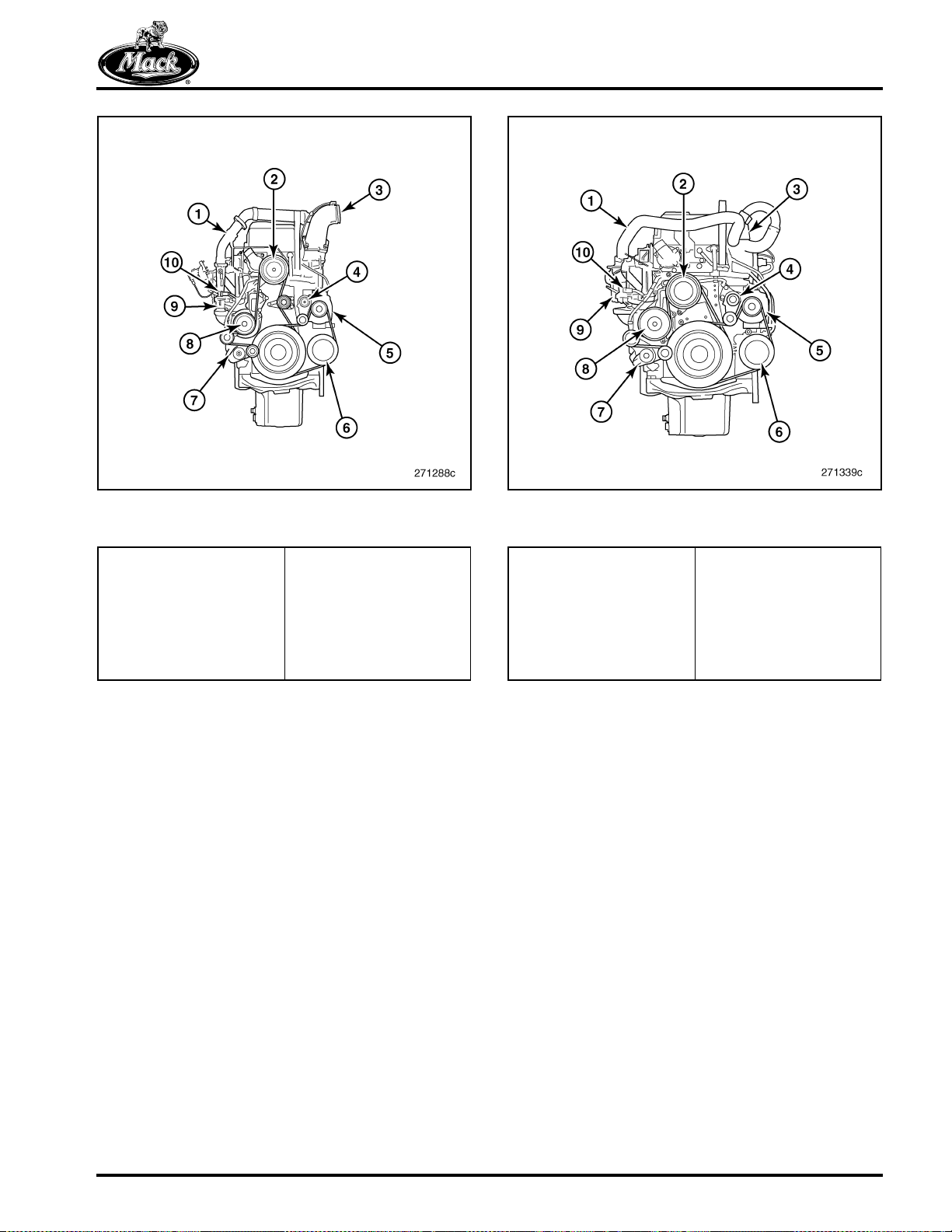
COMPONENT LOCATOR
42
Figure 42 — MACK MP8 Engine, Front View,
Conventional Chassis
1. EGR Cooler Outlet Pipe
2. Fan Drive
3. EGR Mixer
4. Belt Tensioner
(Alternator/Refrigerant
Compressor Belt)
5. Alternator (Pad Mount)
6. Refrigerant Compressor
(Pad Mount)
7. Belt Tensioner (Fan
Drive/Water Pump Belt)
8. Water Pump
9. Venturi
10. Differential Pressure
Sensors
43
Figure 43 — MACK MP8 Engine, Front View, LCF
Chassis
1. EGR Cooler Outlet Pipe
2. Fan Drive
3. EGR Mixer
4. Belt Tensioner
(Alternator/Refrigerant
Compressor Belt)
5. Alternator (Pad Mount)
6. Refrigerant Compressor
(Pad Mount)
7. Belt Tensioner (Fan
Drive/Water Pump Belt)
8. Water Pump
9. Venturi
10. Differential Pressure
Sensors
Page 51
Page 63

NOTES
Page 52
Page 64

TROUBLESHOOTING
TROUBLESHOOTING
Page 53
Page 65

TROUBLESHOOTING
ENGINE SYMPTOM DIAGNOSIS
[200 EA]
The Vehicle Management and Control (V-MAC
IV) system monitors engine function and displays
a code when a fault is detected. The code can be
observed on the instrument panel or through an
electronic diagnostic tool. An explanation of the
fault codes can be found in VCADS, Guided
Diagnostics or the Fault Code Manual, 8-218.
Guided Diagnostics also includes
symptom-based troubleshooting. To obtain Tech
Tool, contact your local MACK dealer.
The Tech Tool provides complete system
diagnostics. For more information, see manual
8-371 or the Tech Tool web site. Repair
information is available in the respective engine
service manuals and from the MACK Electronic
Information System (EIS). EIS is easily accessed
w i t h Te c h To o l .
Troubleshooting Technique
Depending on the vehicle configuration, a
problem may be caused, or influenced, by
malfunctions in other vehicle components. Be
sure to inspect for unusual conditions among the
batteries, tires, axles, trailer, bodybuilder
adaptations and other possibilities. Consult
specific service information resources according
to the conditions observed. Fuel waxing, for
example, can cause symptoms easily mistaken
for other engine problems.
If possible, recreate the problem in an
environment similar to that described by the
vehicle operator. Run the engine at the
temperature at which the symptom occurred.
Engine problems can be electrical, mechanical or
a combination of the two. Electrical and electronic
problems will, for the most part, cause fault codes
to be set in the V-MAC system.
Before Troubleshooting Begins
Before troubleshooting begins, observe all shop
safety procedures.
Talk to the vehicle operator. Learn how the engine
operated before it failed. Ask about the
maintenance schedule and the fuel, coolant and
lubricant used. Begin by attempting to determine
whether anything has happened recently that
could point to the electrical system, but which is
not related to the electronic control system.
Page 54
Page 66

TROUBLESHOOTING
Noise and Vibration
Be sure to discuss noise and vibration issues with
the driver. It is important to discover under what
conditions these occur. Maybe a test drive will be
NORMAL VERSUS ABNORMAL
Noise is the name we give to vibration that
irritates us through our ears. Vibration can be felt
without being heard. Engine operation can cause
vibration and noise throughout a vehicle that we
regard as “normal.”
Abnormal noises and vibrations suggest that
something is not working properly or is not
necessary to familiarize yourself with the details
of the driver's story. Even so, it will probably be
necessary to start the diagnostic process with a
guess as to the nature of the difficulty.
The table below affords an opportunity to make
note of various influences discovered while
investigating the problem and organize thoughts.
It is made for you to use as you see fit.
assembled properly. A damaged driveshaft can
cause abnormal vibration. A loose fastener allows
two surfaces to rub or slap together causing
unusual noise in response to the vibration.
The noise or vibration occurs: Yes No Remarks
When the vehicle is stationary
At idle Engine Speed =
When power take-off is engaged Engine Speed =
Other items of interest
When the vehicle is in motion
With a particular superstructure
At a particular weight
At a particular speed
On a particular type of road
Driving without cruise control
Driving with cruise control
Driving using the speed governor
At full load
In a particular gear
When freewheeling (clutch
disengaged)
Vehicle information
Type of chassis suspension (air?)
Type of cab suspension (air?)
Type of driver's seat (make and
model)
Other items of interest
Notes:
If the solution does not become evident in the
course of completing the check list above, use
Tech Tool to investigate further.
Page 55
Page 67

TROUBLESHOOTING
ENGINE CHECKS AND TESTS
앫 Cylinder Liner and Piston Wear, Check
앫 EGR Cooler, Pressure Test
Included in this section are the following engine
checks and tests:
앫 Camshaft Sensor Depth, Check
앫 Camshaft Timing, Check
앫 Crankcase Ventilation, Check
앫 Cylinder Head, Pressure Test
앫 Engine Compression, Test
앫 Flywheel Housing Runout, Check
앫 Oil Cooler, Pressure Test
앫 Rocker Arm, Check
앫 Thermostat, Check
앫 Valve Guide Wear, Check
Special Tools
Tool No. Description Image
9989876 Dial Indicator (Available)
9990105 Sealing Plate for MP7 Cylinder Head
9990106 Sealing Plate for MP7, MP8 and MP10
9990107 Connection Disc for MP7, MP8 and MP10
9990164 Sealing Plate for MP10 Cylinder Head
Cylinder Heads
Cylinder Heads
Page 56
Page 68

TROUBLESHOOTING
Tool No. Description Image
9996662 Pressure Gauge and Hoses (Available)
9996956 Flywheel Turning Tool for MP7 Engine
9999683 Sweep Dial Indicator (Essential)
9999696 Magnetic Stand (Available)
(Essential)
85109036 Cylinder Head Lifting Tool (Essential)
Page 57
Page 69

TROUBLESHOOTING
Tool No. Description Image
88800014 Flywheel Turning Tool for MP8 and MP10
Engines (Essential)
88800031 Camshaft Sensor Depth Gauge (Available)
88800215 Sealing Plate
88800216 EGR Cooler Test Kit
J 5347-B Dial Bore Gauge
J 42753 Fuel Line Kit
J 47364 Cylinder Head Adapter Plate
Page 58
Page 70

TROUBLESHOOTING
Camshaft Sensor Depth, Check
The signal from the camshaft sensor must
exceed 0.5 volt in order to start the engine. If the
signal is low, check the depth setting of the
sensor following this procedure.
1. Remove the plug from the flywheel housing
and install the appropriate flywheel turning
tool, 9996956 (MP7) or 88800014 (MP8 and
MP10).
2. Check for proper camshaft position sensor
clearance using the sensor depth gauge,
88800031, to determine if shims are
required for sensor depth.
44
d. Tighten the thumb screw to secure the
inner part of the gauge.
e. Carefully remove the gauge from the
camshaft sensor bore and observe the
location of steps between the inner and
outer portions of the gauge (Figure 45):
앫 Both steps below the surface of
the gauge = no shims required.
앫 One step below the surface of the
gauge = one shim required.
앫 Both steps above the surface of
the gauge = two shims required.
45
Figure 44 — Using Gauge at Camshaft Sensor Location
a. Rotate the engine until a tooth of the
camshaft toothed wheel is aligned with
the sensor bore.
b. Insert the depth gauge into the sensor
bore until the outer part of the gauge is
fully seated against the timing gear
cover.
c. Loosen the thumb screw of the gauge
and push the inner part of the gauge in
until it contacts a tooth of the toothed
wheel.
Figure 45 — Depth Gauge
3. Install the camshaft position sensor with the
appropriate shim(s) and new O-ring. Secure
the sensor with a bolt and plug in the
harness connector.
Page 59
Page 71

TROUBLESHOOTING
Camshaft Timing, Check
1. Remove the cylinder head (valve) cover.
2. Check the camshaft vibration damper for
damage to the pulse wheel pins.
3. Check the pulse wheel mounting for secure,
square attachment.
4. Turn the engine crankshaft so that the TDC
mark on the camshaft corresponds to the
marks on the camshaft bearing cap No. 7
(MP7) or camshaft bearing cap No.1 (MP8
and MP10) and the flywheel TDC mark “0” is
opposite the pointer on the flywheel housing.
5. To ensure that the camshaft is correctly
installed, complete a valve lift check on the
intake valves of cylinder No. 1.
앫 Temporarily adjust the No. 1 inlet rocker
arm, at the valve yoke, to zero lash.
앫 Position a dial indicator at the inlet
valve yoke for the No. 1 cylinder.
앫 Preload the dial indicator and reset the
dial to align with zero.
앫 Turn the engine in the normal direction
of engine rotation one full rotation to “0”
and past to the mark 6 degrees (after
TDC) on the flywheel.
Crankcase Ventilation, Check
1. Check the inlet pipe to the CCV separator for
oil film, oil residue and particles. Remove
any accumulated oil and dirt particles from
the pipe.
46
Figure 46 — CCV Inlet Pipe Connection
2. Remove the CCV separator from the engine.
3. With the separator removed, rotate the
turbine by hand. It should rotate easily. If it
does not rotate easily, replace the separator
unit.
47
앫 The dial indicator travel reading should
be approximately 1.6 ±0.03 mm
(0.06 ±0.01 inch) for MP7 and MP8 or
1.4 ±0.03 mm (0.05 ±0.01 inch) for
MP10. This reading indicates a
correctly timed camshaft.
앫 Readjust the cylinder No. 1 inlet valves
and yoke.
If the camshaft is one tooth out of time, the dial
indicator reading will be approximately 0.762 mm
(0.030 inch) out of specification and should
experience a fault code for the camshaft sensor.
6. Install the cylinder head (valve) cover.
Figure 47 — CCV Separator Turbine Wheel
Page 60
Page 72

TROUBLESHOOTING
4. Check the oil nozzle in the CCV base for dirt
and any accumulated oily deposits. Clean
the nozzle as required. If unable to clean the
nozzle sufficiently, replace the complete
CCV separator assembly.
48
Figure 48 — Oil Nozzle (Separator Base)
If the oil nozzle becomes clogged, the oil
pressure is reduced and the turbine does not
rotate as it should.
49
Figure 49 — Sealing Plates Installed (Typical)
1. Sealing Plates (Cooling
Por ts)
2. Sealing Plate (By-Pass
Por t)
3. Connection Disc
(Thermostat Housing)
Cylinder Head, Pressure Test
(Cylinder Head Removed)
The following procedure applies for MACK MP7,
MP8 and MP10 engine cylinder heads. While the
procedure is typical, the sealing tools required will
be different for each MP engine series.
1. Clean the contact surfaces on the cylinder
head. Install the:
앫 Sealing plates, 9990105 (MP7),
9809696 and 9998266 (MP8) or
9990164 (MP10), onto the cylinder
head coolant ports using cylinder head
bolts and M16 nuts
앫 Connection disc, 9990107, in position
on the thermostat housing bore
앫 Plug, M12x1.5, in the temperature
sensor hole
앫 Sealing plate, 88800215, on the side of
the cylinder head
2. Connect the pressure gauge, 9996662, to a
suitable air supply. Connect the pressure
gauge hose to the connection disc on the
cylinder head. Adjust the pressure to
100 kPa (14.5 psi) using the control valve.
Close the stop valve for two minutes. The
pressure should not fall.
3. Lower the pressure in the cylinder head by
adjusting the knob on the pressure gauge
control valve.
50
Figure 50 — Pressure Gauge Adjustment Knob
Page 61
Page 73

TROUBLESHOOTING
4. Attach the cylinder head lifting tool,
85109036, to the cylinder head.
5. Using a hoist, lower the cylinder head into a
container suitable for the pressure test. Fill
the container with 70°C (158°F) water.
51
Figure 51 — Testing for Air Leaks
A drop in pressure and the appearance of air
bubbles indicates a leak(s) in the coolant, fuel or
oil passages. The source of the leak(s) must be
found and the cylinder head repaired or replaced
as required.
9. Lower the pressure in the cylinder head by
adjusting the knob on the pressure gauge
control valve.
10. Using a hoist, remove the cylinder head from
the water container.
11. Remove the sealing plates and connection
disc from the cylinder head. Using
compressed air, blow the water off the
cylinder head and out of all threaded holes.
Use care with the fuel passages to make sure
that no dirt enters the fuel channels. Dirt can
cause the unit injectors to be damaged.
6. With the pressure gauge connected to an air
supply and the connection disc on the
cylinder head, carefully open the gauge
control valve.
7. Set the pressure to 50 kPa (7.25 psi) and
hold the pressure for one minute.
8. Raise the pressure to 150 kPa (21.8 psi) and
close the stop valve. After two minutes,
check for a drop in pressure and for any air
bubbles forming around the cylinder head.
Page 62
Page 74
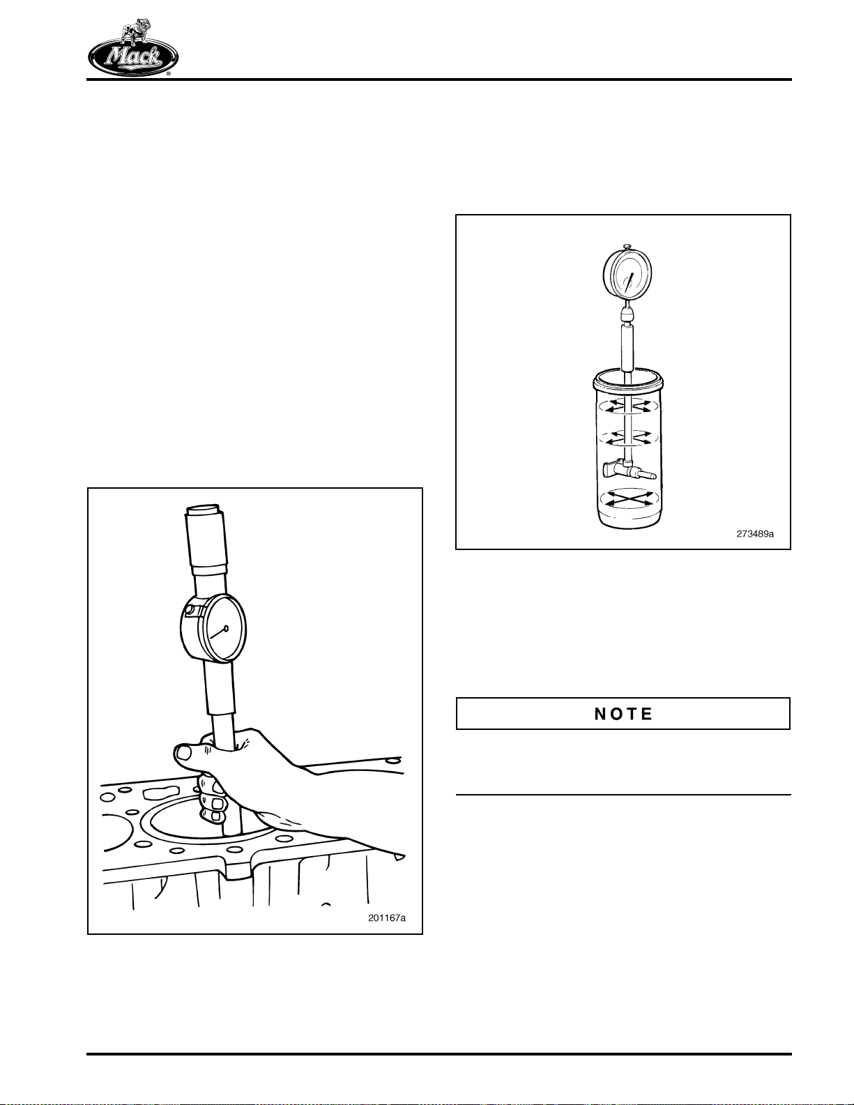
TROUBLESHOOTING
Cylinder Liner and Piston Wear,
Check
Thoroughly clean the cylinder liners and pistons
before inspecting and measuring. To thoroughly
check for cracks, remove the cylinder liner from
the cylinder block. Mark the position of the
cylinder liner in the cylinder block before
removing it so it can be installed in the same
position during assembly.
CYLINDER LINER
1. Check the cylinder liner for cracks, paying
special attention to the liner flange. The
standard dye penetrant or Magnaflux
method can be used for checking.
2. Measure the cylinder liner wear with a
cylinder bore gauge. The original bore size
of the cylinder liner can be used as a
reference measurement.
52
®
3. Measure the cylinder liner at Top Dead
Center (TDC), at Bottom Dead Center
(BDC) and at a couple of positions in
between. At each point, measure in two
directions — engine crosswise and engine
lengthwise.
53
Figure 52 — Measuring Cylinder Liner Wear
Figure 53 — Measurement Locations
4. If wear is greater than 0.05–0.10 mm
(0.002–0.004 inch), use a complete liner kit
(cylinder liner, piston, piston rings, piston pin
and cylinder liner seals). Also consider
engine oil consumption to determine when
to replace the cylinder liner.
Pistons and cylinder liners are available from
stock only as matched pairs and should not be
mixed.
Page 63
Page 75

TROUBLESHOOTING
PISTON
Inspect the piston ring grooves, lands, skirt and
combustion bowl for wear, scuff marks, deep
scratches, cracks and blow-by. Pistons are NOT
repairable. Discard worn or damaged pistons.
Do not stamp or engrave on the TOP of the
piston. Failure to heed this caution may result in
severe engine damage.
To ensure that pistons are reinstalled into the
same cylinders, the pistons must be tagged with
the corresponding cylinder number when
removed during disassembly.
EGR Cooler, Pressure Test
(Not Applicable for MP8 Euro 3
Engine)
1. Check inside the gas inlet port. If build-up of
soot is seen, perform the EGR cooler
cleaning procedure before checking for
leaks.
54
Figure 54 — Installation of Leak Test Kit on Cooler
1. 88800216-1
2. 88800216-2
3. Flange Capscrew
4. Flange Nut
5. U-Bolt
6. 9996662
7. 9998333
3. Fill a container with enough water to cover
the EGR cooler.
4. Lower the EGR cooler into the container of
water at room temperature (or fill the cooler
core with water — see NOTE).
55
2. Lubricate the O-rings on the coolant inlet
and outlet port plugs with a suitable O-ring
lubricant. Install the plugs and cap on the
EGR cooler. Install the plugs on the EGR
cooler coolant inlet and outlet ports. Install
the coupler on the plug and connect the
gauge to the coupler.
Do NOT over-tighten the fasteners on the plugs
and cap.
Figure 55 — Conducting Pressure Test
Page 64
Page 76

TROUBLESHOOTING
If a large enough container cannot be obtained,
the EGR cooler can be tested without being
immersed in water by using the test plugs
included with the kit, 88800216-5, to seal the gas
outlet port. The EGR cooler core can then be
filled with water and tested by applying air
pressure to the coolant outlet port as shown in
Figure 56. When using this technique, the cooler
must be tested in the upright position.
To ease the installation of the test plug, coat
the inside of the hose with a suitable O-ring
lubricant.
56
If the cooler is being tested without being
immersed in water, look inside the gas inlet port.
If bubbles are seen, the cooler is leaking
internally and must be replaced.
A stream of bubbles seen coming from around
the plugs in either of the coolant ports indicates
that the O-rings may be damaged. If this is the
case, remove the plugs, inspect the O-rings and
replace as required.
6. Lift the EGR cooler out of the container and
remove the pressure testing equipment.
7. Dump the water from inside the EGR cooler
and then use compressed air to remove any
remaining water from the cooler core and
outer cover.
Engine Compression, Test
Figure 56 — Test with EGR Gas Outlet Port Plugged
1. Test Plug, 88800216-5 2. EGR Cooler
5. Apply air pressure (240 kPa [35 psi]) to the
EGR cooler. Maintain the pressure for
15 minutes. If the EGR cooler is leaking
internally, there will be a steady stream of
bubbles coming from the gas inlet or outlet
openings. If a steady stream of bubbles
appears, replace the EGR cooler.
(on Vehicle)
Verify suspected leaks in the cylinder head or
block by pressure testing before replacing these.
Do not use Magnaflux
replacement criteria.
Before proceeding with the tests, look for coolant
stains around the sealing plugs on the cylinder
head. Check that the plugs are installed properly
and in good condition.
1. Remove the cylinder head (valve) cover.
On engines fitted with PowerLeash™, secure the
pistons in the rocker arms with rubber bands or
tie straps so the pistons do not drop out when the
rocker assembly is lifted. Pistons and rockers are
matched together. Failure to heed this caution
may result in severe component damage.
®
inspections alone as
Page 65
Page 77

TROUBLESHOOTING
57
7. Install the PowerLeash™ control valve and
oil tube between the valve and the rocker
arm shaft as follows:
앫 Lubricate and assemble the seals on
each end of the oil tube.
앫 Insert the larger end of the oil tube in
the rocker shaft.
앫 Make sure the oil seal is in place at the
bottom of the valve assembly.
앫 Position the valve assembly on the
mounting plate and insert the free end
of the oil tube.
앫 Using a torque wrench, tighten the
attaching screws according to
specification.
58
Figure 57 — Tie Strap Holding Engine Brake Piston (MP7
Shown)
2. Remove the PowerLeash™ (engine brake)
control valve if so equipped.
It is very important to loosen the rocker arm shaft
assembly uniformly across the complete shaft.
Loosening the rocker shaft assembly unevenly
can cause damage.
3. Install the appropriate lifting tool, 85109050
(MP7), 85109250 (MP8) or 85109035
(MP10), on the rocker arm assembly.
Loosen the rocker arm shaft uniformly
across the complete shaft. Remove the
rocker arm assembly.
4. Remove the unit injectors and clean the
copper sleeves if necessary.
5. Install an adapter, J 47363, in each of the
unit injector ports.
6. Refit the rocker arm assembly to the engine.
Figure 58 — Engine Brake Control Valve Oil Tube
1. Control Valve
2. Oil Tube
Orientation (MP7 Only)
3. Rocker Arm Shaft
8. Connect a remote starter switch to the
starter.
Do not run the starter motor for longer than
15 seconds at a time. Wait 60 seconds before
trying again.
Page 66
Page 78

TROUBLESHOOTING
9. Connect the compression gauge, J 6692-B,
to the adapter on the first cylinder. Crank the
engine with the remote starter switch until
the needle on the compression gauge stops
moving (maximum compression). Record
and repeat for all remaining cylinders.
10. Remove the screws for the PowerLeash™
control valve.
11. Remove the control valve and the oil tube
between the valve and the rocker arm shaft.
12. Install the lifting tool, 85109050 (MP7),
85109250 (MP8) or 85109035 (MP10), on
the rocker arm assembly. Loosen the rocker
arm shaft uniformly across the complete
shaft. Remove the rocker arm shaft
assembly.
13. Remove the J 47363 adapters from all of the
cylinders.
14. Install the unit injectors using new O-rings
and new sealing washers.
15. Connect the wiring harness to the unit
injectors.
20. Tighten the control valve screws according
to specification and then connect the wiring
harness to the valve assembly.
21. Adjust the valve and the unit injector rockers.
22. Install the cylinder head cover.
23. Bleed the fuel system.
Flywheel Housing Runout, Check
(Clutch Removed)
CHECKING AXIAL AND RADIAL RUNOUT
1. Clean the flywheel and flywheel housing.
2. Remove the plug from the flywheel housing
and install the appropriate flywheel turning
tool, 9996956 (MP7) or 88800014 (MP8,
MP10).
59
16. Carefully lower the rocker arm shaft
assembly onto the head.
17. Remove the lifting tool from the rocker arm
shaft.
It is very important to tighten the rocker arm shaft
assembly uniformly across the complete shaft.
Tightening unevenly can cause damage to the
rocker arm shaft assembly.
18. Tighten the rocker arm shaft screws in the
sequence specified.
19. Install the PowerLeash™ control valve and
oil tube between the valve and the rocker
arm shaft making sure the sealing rings are
correctly positioned before tightening the
screws.
If the oil tube is installed incorrectly with the large
end in the control valve and the small end in the
rocker arm shaft, oil leaks will occur. This may
cause oil starvation in the rocker arms which can
result in engine failure.
Figure 59 — Turning Flywheel (MP8 Shown, Typical)
3. To check axial runout, attach the dial gauge
to the flywheel using the magnetic base and
position its tip against the outer flange
(transmission mounting surface) of the
flywheel housing. Set the dial gauge to zero.
4. Rotate the flywheel and note the indicated
runout at a minimum of four locations around
the outer flange of the housing. Compare the
noted runout with the specified axial runout
tolerance.
Page 67
Page 79

TROUBLESHOOTING
60
Figure 60 — Checking Axial Runout
1. Magnetic Stand,
9999696
2. Sweep Dial Indicator,
9999683
61
Figure 61 — Checking Radial Runout
1. Dial Gauge, 9989876 2. Magnetic Stand,
9999696
5. To check radial runout, position the tip of
the dial gauge against the inner flange of the
flywheel housing. Rotate the flywheel and
note the indicated runout, again at a
minimum of four locations around the inner
flange of the housing. Compare the noted
runout with the specified radial runout
tolerance.
6. If the runout values are out of specification,
check the mating surface for the flywheel
housing against the engine block and the
mating surface for the flywheel on the
crankshaft. Do this before replacing the
flywheel housing.
7. Remove the flywheel turning tool and
reinstall the plug in the flywheel housing.
Page 68
Page 80

TROUBLESHOOTING
Oil Cooler, Pressure Test
1. Clean the coolant side of the oil cooler with a
water-soluble degreasing fluid. Flush the oil
side of the cooler with degreasing solvent.
2. Install the clamp tools, 9996845, making
sure they are properly seated.
62
Figure 62 — Clamp Tools, Installed
3. Adjust the pressure gauge reduction valve
knob until the pressure gauge needle is at
zero.
4. Connect the pressure gauge assembly to
the fitting on the clamp. Lower the oil cooler
into a bath of water. The water temperature
should be at approximately 70°C (160°F).
63
Air bubbles emerging from the oil cooler indicate
a leak. The oil cooler should be replaced.
Rocker Arm, Check
Make sure there is clearance between the rocker
arm rollers and the camshaft when performing
the following rocker arm bushing and roller
bushing checks.
ROCKER ARM BUSHINGS
1. Install the appropriate flywheel turning tool,
9996956 (MP7) or 88800014 (MP8 and
MP10), and turn the engine until the
camshaft is in a position where the rocker
arm roller being checked is on the base
circle of the camshaft lobe. Make sure that
there is clearance between the roller and
camshaft.
To check the injector, the rocker arm roller must
be on the base circle of the camshaft lobe and
the injector adjusting screw backed off (preload
must be readjusted).
Figure 63 — Testing Oil Cooler
5. Increase the pressure to 250 kPa (35 psi)
using the reduction valve knob and check for
air bubbles emerging from the oil cooler. The
test period should last for at least one
minute.
Page 69
Page 81

TROUBLESHOOTING
2. Position the magnetic stand, 9999696, and
dial indicator, 9989876, so that the tip of the
indicator is on top of the rocker arm above
the middle of the rocker arm shaft bushing
area.
64
65
Figure 65 — Prying Rocker Arm Up
6. Repeat the check on all other rocker arm
bushings.
Figure 64 — Dial Indicator Positioning
3. Push down on the rocker arm so that any oil
film is forced out of the upper side of the
rocker arm shaft.
4. Set the dial indicator to zero.
5. Position a pry bar directly under the rocker
arm in the shaft area. Pry the rocker arm up
and note the reading on the dial indicator.
The maximum clearance allowed between
the rocker arm and shaft is 0.1 mm
(0.0039 inch). If the clearance is greater,
replace the rocker arm and check the shaft
for wear.
ROCKER ARM ROLLER BUSHINGS
1. Using the flywheel turning tool, 9996956
(MP7) or 88800014 (MP8 and MP10), turn
the engine until the camshaft is in a position
where the rocker arm roller being checked is
on the base circle of the camshaft lobe.
2. Make sure there is clearance between the
rocker arm roller and the camshaft lobe.
To check the injector, the rocker arm roller must
be on the base circle of the camshaft lobe and
the injector adjusting screw backed off (preload
must be readjusted).
Page 70
Page 82

TROUBLESHOOTING
3. Rotate the roller a few turns so that the oil
film between the roller bushing and shaft is
forced out. If the roller jams, is sticky or
rough, the rocker arm should be replaced.
66
Figure 66 — Forcing Oil from Roller
4. Place the dial indicator, 9989876, into the
magnetic stand, 9999696, and position the
magnetic stand as level as possible on the
rocker arm.
67
Check that the tip of the dial indicator is
pre-tensioned and can move in both directions.
6. Place a screwdriver between the rocker arm
and the roller. Carefully pry the roller out as
far as possible and note the value on the dial
indicator.
Use care when prying or pressing on the roller to
avoid damage to the surface of the roller.
68
Figure 67 — Dial Indicator Positioning
5. Adjust the tip of the dial indicator so that it is
horizontal to the center of the roller. Zero the
dial indicator.
Figure 68 — Prying Roller Out
7. Using a blunt object, press the roller in as far
as possible. Note the reading on the dial
indicator. The maximum clearance allowed
between the roller bushing and shaft is
0.1 mm (0.0039 inch). If the clearance is
greater than this, replace the rocker arm.
Page 71
Page 83

TROUBLESHOOTING
69
Figure 69 — Pressing Roller In
8. When replacing a rocker arm, lubricate the
new rocker arm roller bushing with clean
engine oil. Use an oil can and insert the
nozzle into the oil channel passage. Rotate
the roller while lubricating and check that oil
comes out on both sides of the roller.
70
Thermostat, Check
With the thermostat removed from the engine,
check its operation as follows:
1. Check to be sure that the thermostat closes
fully. This can be done by holding it up to the
light to verify that there is no visible gap at
the opening point. If the thermostat does not
close properly, replace it.
2. Add water to a suitable container and warm
the water to 75°C (167°F). With the water
warmed, immerse the thermostat in the
water. Use a piece of wire attached to the
thermostat.
71
Figure 70 — Lubricating Rocker
9. Repeat the check on all other rocker arm
roller bushings as necessary.
Page 72
Figure 71 — Thermostat Closed
3. After at least 30 seconds, check that the
thermostat is still closed.
Page 84
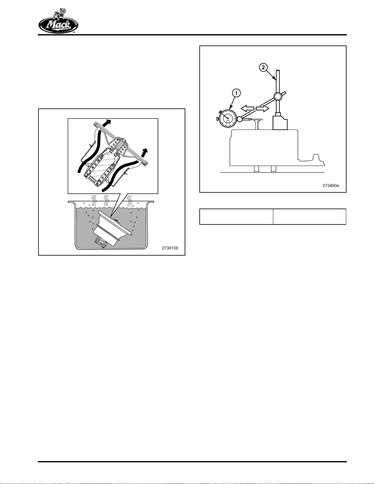
TROUBLESHOOTING
4. Now warm the water to 100°C (212°F). After
at least 30 seconds at the boiling point,
check that the thermostat has opened
approximately 16 mm (0.63 inch). If the
thermostat has not opened, it must be
replaced. A good thermostat starts to close
at approximately 92°C (198°F) and is fully
closed at approximately 82°C (180°F).
72
73
Figure 73 — Measuring Valve Guide Wear
1. Dial Indicator, 9989876 2. Magnetic Stand,
9999696
Figure 72 — Thermostat Open
Valve Guide Wear, Check
WEAR CHECK
1. Remove the oil seals from the valve guides.
2. Mount the cylinder head on a suitable
engine stand using the cylinder head
adapter plate J 47364.
3. Install a new valve into the guide so that the
end of the valve stem is even with the valve
guide edge.
4. Using the dial indicator 9989876 and holder
9999696, place the tip of the dial indicator
against the edge of the valve disc. Move the
valve back and forth laterally in the direction
of the intake/exhaust ports. Note the
measured value and compare it with the
acceptable wear limit specified for the
engine.
5. Repeat Step 4 to check all valve guides.
Replace the valve guides if the measured
values exceed the acceptable wear limit.
Page 73
Page 85

NOTES
Page 74
Page 86

MAINTENANCE
MAINTENANCE
Page 75
Page 87

MAINTENANCE
LUBRICATION SYSTEM MAINTENANCE
Special Tool
Tool No. Description Image
9998487 Oil Filter Wrench (Available)
Oil Level Check
When checking oil levels, the vehicle must be
parked on level ground. Components must be
filled to the correct level. DO NOT OVERFILL.
The best time to check oil level is while the engine
is COLD (prior to starting at the beginning of the
work day, or after the vehicle has sat
approximately 2 hours). At normal operating
temperature (engine oil temperature above 80°C
[175°F]), oil level can be checked 15 minutes
after shut down.
Failure to wait a sufficient amount of time (2 hours
if engine oil temperature is below 80°C [175°F])
or 15 minutes if oil temperature is above 80°C
[175°F]) will result in an inaccurate dipstick
reading.
For accurate oil level readings, the dipstick must
be inserted fully into the dipstick tube. The level
must be close to the FULL line (at least between
the LOW and FULL lines) on the dipstick, but
must NOT exceed the FULL line.
74
Figure 74 — Oil Level Check
Page 76
Page 88

MAINTENANCE
Oil and Filter Change Procedure
[219 EV]
This engine is equipped with improved spin-on
type oil filters.
DISPOSABLE SPIN-ON OIL FILTER
REPLACEMENT
Change oil and replace oil filters using the
following procedure:
Install new filters dry.
1. Run the engine until normal operating
temperature is reached. Then, shut off the
engine and drain the oil before the engine
cools.
2. Thoroughly clean the area around the filters
before removing.
Crankcase Ventilation System
The crankcase ventilation (CCV) system
separator is not repairable. If there is apparently
faulty operation, perform these inspections before
replacing the separator.
1. Inspect the separator inlet hose and
connectors at the valve cover and at the
separator. Remove any obstruction, oil film,
residue and particles.
2. Inspect the separator outlet hose and
connector. Remove any obstruction, oil film,
residue and particles.
3. Remove the separator and attempt to turn
the turbine manually. If it does not turn
easily, replace the separator.
4. If the turbine turns easily, inspect and clean
the oil jet nozzle.
5. Reassemble the separator and the hoses.
6. If faulty operation continues, continue fault
tracing with Guided Diagnostics.
3. Using filter wrench 9998487 or equivalent,
remove the spin-on filters and wipe the filter
mounting base clean.
4. Fill each filter with 1.9 liters (2 quarts) of the
specified engine oil. DO NOT allow any
contaminants to enter the filters while filling.
5. Apply a film of clean engine oil to the sealing
gasket on each new filter.
6. Install the filters and tighten 3/4 to 1 turn
after the gasket contacts the base.
7. Fill the crankcase with the recommended
engine oil. If the engine is equipped with a
REPTO unit, add one additional quart.
8. Start the engine and check for leaks. Run
the engine for approximately five minutes,
then shut it off and recheck the oil level. Add
oil if necessary.
Use of anything other than genuine MACK filters
may cause damage and void the engine warranty.
Change filters according to the recommended
maintenance schedule.
Page 77
Page 89

MAINTENANCE
FUEL FILTER REPLACEMENT
Fuel Filter Change
[231 BA]
FILTER DESCRIPTION
Two filters ensure that clean, waterless fuel
reaches the electronic unit injectors. One is a
full-flow filter, the other is a water separating
pre-filter with a transparent cup to collect and
drain the water. A water-in-fuel sensor informs the
driver of excessive accumulation in the cup. The
water separating pre-filter is in the “suction side”
of the fuel circuit. It is a spin-on type with one end
of its casing threaded to receive the cup.
The full-flow main filter is on the “pressure side”
of the circuit. It is also an easily replaced spin-on
filter. The casing completely encloses the filter
element. This filter is rated at 3–5 microns.
75
FUEL FILTER REPLACEMENT
Because of ice buildup or fuel waxing which can
clog fuel filters, it may be necessary during
extremely cold weather to reduce the time or
mileage interval between fuel filter changes.
Be careful to prevent foreign matter of any kind
from entering the filters during service.
Install new fuel filters dry.
Water Separating Pre-Filter Replacement
To replace the water separating pre-filter:
1. Disconnect the electrical cable.
2. Make sure the filter casing is thoroughly
cleaned. If not already done, wash the area
around the filter mounting adapter with a
suitable solvent and blow dry with
compressed air.
Figure 75 — Fuel Filters
1. Water Separating
Pre-Filter
2. Water Separator Bowl
3. Water-in-Fuel Sensor
Harness
3. With a suitable container in place to collect
spillage, open the fitting and drain the filter.
4. Unscrew and remove the water cup.
5. Using a filter wrench, remove the filter from
the mounting bracket and discard it safely.
6. Apply a thin film of clean engine oil to the
sealing gasket of the new filter.
7. Screw the new dry filter in place and tighten
an additional 3/4 to 1 turn by hand after the
gasket contacts the base.
After filter installation, operate the hand primer to
fill the fuel filters before attempting to start the
engine.
8. Screw the water cup into the filter casing.
4. Drain Assembly
5. Full-Flow Main Filter
Page 78
Page 90
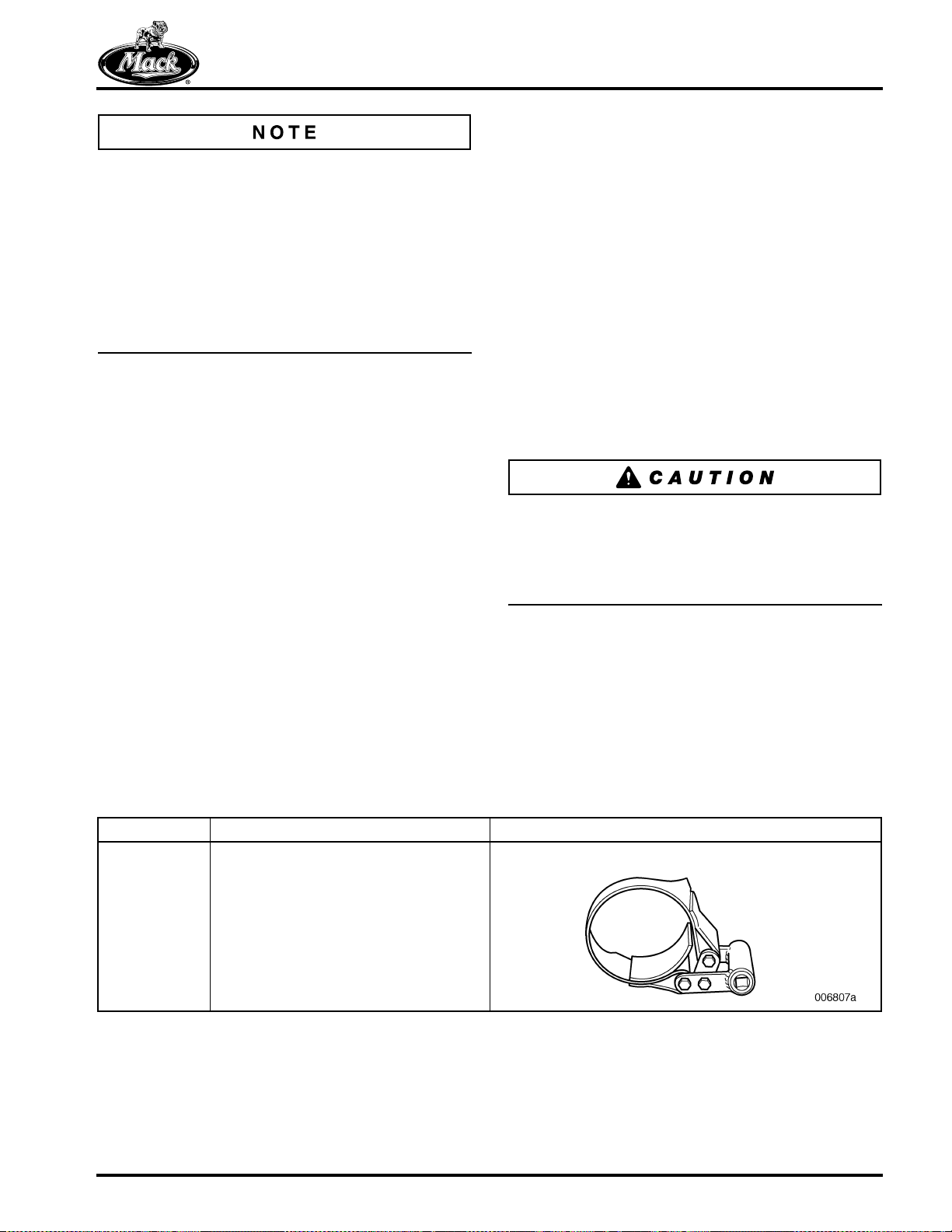
MAINTENANCE
2. Put a suitable container in place to collect
spillage.
There is a new-style pre-filter with a
stepped-down diameter at the bottom of the filter.
The earlier-style filter has straight sides with a
larger bottom diameter which requires an adapter
to attach the fuel/water separator bowl to the
filter. When replacing the previous straight-sided
filter with the current stepped-down version, the
adapter is not used. However, do not discard the
adapter as it can be used should inventory of the
earlier-style filter still be available.
9. If necessary, replace the full-flow main filter.
See the following instructions.
10. Connect the electrical cable.
11. Start the engine and run at idle for five
minutes to fill the filter with fuel.
12. Check for leaks.
Full-Flow Main Filter Replacement
To replace the full-flow main filter:
1. Make sure the filter casing is thoroughly
cleaned. If not already done, wash the area
around the filter mounting adapter with a
suitable solvent and blow dry with
compressed air.
3. Using a filter wrench, remove the filter
casing from the mounting bracket and
discard it.
4. Apply a thin film of clean engine oil to the
sealing gasket of the new filter.
5. Screw the new dry filter in place and tighten
an additional 3/4 to 1 turn by hand after the
gasket contacts the base.
6. If necessary, replace the water separating
pre-filter. See the preceding instructions.
7. Start the engine and run at idle for five
minutes to fill the filter with fuel.
8. Check for leaks.
Severe engine damage may be caused by
attempting to prime the fuel system using an
auxiliary pump or by applying air pressure in the
fuel tank. These techniques may destroy seals
that prevent fuel from leaking into the crankcase.
COOLING SYSTEM MAINTENANCE
Special Tool
Tool No. Description Image
J 48061 Coolant Filter Wrench (Available)
Page 79
Page 91
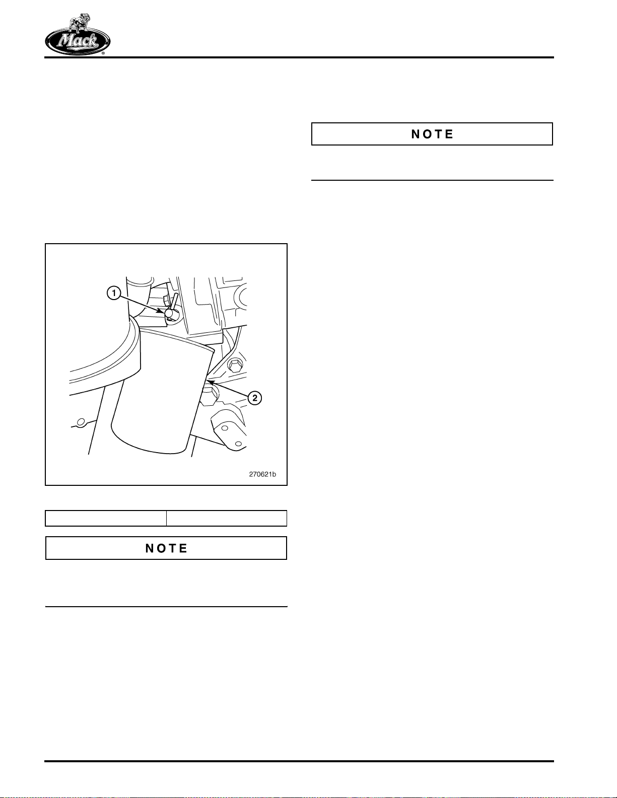
MAINTENANCE
Coolant Drain Outlets
Extra outlets provide convenient drain sites for
use during maintenance and other procedures
involving coolant.
Coolant Filter
The coolant filter attaches to the back of the
coolant pump housing. It resembles a spin-on oil
filter. The filter element and casing are replaced
as a unit.
76
REMOVE AND REPLACE
1. Close the shut-off valve on the coolant pump
housing.
In the closed position, the pin on the shut-off
valve should be horizontal.
2. Place a suitable container below the filter to
collect spilled coolant.
3. Using filter wrench J 48061 or equivalent,
unscrew the filter and discard it safely.
4. Apply a light film of coolant on the face of the
new filter gasket.
5. Screw the new filter on the threaded nipple
extending from the mounting flange.
6. Using the filter wrench, tighten the filter one
full turn after the gasket contacts the base.
7. Open the shut-off valve on the coolant pump
housing.
Figure 76 — Coolant Filter
1. Shut-Off Valve 2. Coolant Filter
For Australia, engines are not equipped with the
coolant filter. VCS coolant is used to protect the
cooling system.
8. Check for any coolant leaks.
Page 80
Page 92

MAINTENANCE
EXHAUST AFTERTREATMENT SYSTEM MAINTENANCE
Special Tools
Tool No. Description Image
9996049 Coolant Drain Hose (Available)
85111327 VBOC DPF Support Stand
DBT2V700 Coolant Extractor/Injector
Page 81
Page 93

MAINTENANCE
Diesel Particulate Filter
The diesel particulate filter should be removed
from the system and replaced at the
recommended service interval. If the filter is not
replaced, it will become clogged and increase
exhaust back pressure. As back pressure
increases, engine power and economy decline as
does the ability of the system to remove
undesirable emissions.
SPACE SAVER UNIT
The components reach high temperatures
during use. Ensure that the unit has cooled to
the touch before handling. Failure to heed this
warning may result in severe personal injury.
Removal
1. When the fairing (if present), braces and
steps have been removed to permit access,
remove the lines and sensors connecting the
inlet module to the other modules.
4. Remove the lower exhaust V-band clamp
that connects the DPF outlet module to the
exhaust pipe. Also, remove the V-band
clamp that connects the catalyst module to
the filter module.
78
Figure 78 — Separating DPF Module
5. Position a flat surface jack with a very stable
support (such as a transmission jack) under
the base of the DPF.
79
2. Disconnect wiring and sensor connectors
from the DPF and outlet modules. Cut tie
straps securing the lower portion of the DPF
harness to the muffler body. Also, remove
the pressure differential sensor tube that
connects to the outlet module.
3. Using a marker, make alignment marks on
each of the module sections, above and
below each V-band clamp.
77
Figure 79 — Positioning Transmission Jack
Page 82
Figure 77 — Marking Module Sections
Page 94

MAINTENANCE
6. Remove the fasteners that secure the DPF
lower supporting bracket to the chassis
frame bracket. This releases the weight of
the DPF onto the transmission jack.
80
Figure 80 — Removing DPF from Chassis
7. Lower the DPF unit and roll the transmission
jack from the right side of the chassis to
remove the lower portion of the DPF.
8. Loosen the nut securing the large V-band
clamp between the exhaust outlet module
and the filter module.
9. Separate the DPF from the outlet module.
3. Place a new high-temperature gasket on top
of the DPF module.
4. Perform the following steps to align and lift
the filter and outlet module assembly into
position:
앫 Align the outlet module flange to the
exhaust pipe.
앫 Align the locator tab at the filter module
with the slot located in the bottom of the
catalyst module.
앫 Start all fasteners that connect the
lower supporting bracket to the chassis
frame bracket.
5. Install the V-band clamp that joins the DPF
and catalyst modules. Tighten the band
clamp fastener to specification.
Make sure the high-temperature gasket remains
in place and has not become dislodged.
6. Install and tighten the V-band clamp that
joins the outlet module to the exhaust pipe.
81
10. Remove and discard the gaskets.
11. Inspect and replace the V-band clamps
showing galled threads, cracks or heat
damage. Clean all exposed gasket surfaces.
Installation
1. Install a new gasket between the outlet and
DPF modules.
2. Using alignment marks made at
disassembly, position the DPF over the
outlet module and connect using the V-band
clamp tightened to specifications.
Make sure the high-temperature gasket remains
in place and has not become dislodged.
Figure 81 — Exhaust Pipe-to-Outlet Module Connection
Page 83
Page 95

MAINTENANCE
7. Secure the DPF bracket to the chassis frame
bracket and tighten all fasteners to
specification.
82
Figure 82 — Supporting DPF with Transmission Jack
8. Remove the transmission jack from under
the assembly.
9. Install the pressure differential sensor tube
that connects to the outlet module and
tighten fitting to specification.
11. Install the fairing (if equipped), braces and
steps that were removed to permit access.
12. Using Premium Tech Tool (PTT), ensure all
soot trigger levels are reset back to zero.
VERTICAL BACK-OF-CAB UNIT
The components reach high temperatures
during use. Ensure that the unit has cooled to
the touch before handling. Failure to heed this
warning may result in severe personal injury.
Removal
1. Remove the heat shield, stack, harness
clamps, tie straps and V-band clamp at the
exhaust elbow.
2. Disconnect all harness connectors.
3. Using a suitable lifting device, support the
assembly. Remove the band clamps and
mounting bracket from the stanchion.
84
A high-temperature anti-seizing compound
should always be applied to the threads of the
sensors, plugs and fittings in the exhaust system
to avoid component seizure or corrosion.
10. Install the lines and sensors connecting the
various modules to each other. Refer to
torque specifications for the V-band clamp
screws, lines and sensors in the
SPECIFICATIONS section of this manual.
83
Figure 84 — Supporting DPF Assembly
4. Remove the assembly from the chassis and
place it in the VBOC DPF support stand,
85111327, or equivalent.
Page 84
Figure 83 — DPF Connections
Page 96

MAINTENANCE
5. Using a marker, make alignment marks on
each of the module sections, above and
below each V-band clamp.
85
Figure 85 — Marking Module Sections
6. Remove the pressure differential tube from
the catalytic filter module.
7. Remove the V-band clamp joining the outlet
module to the filter module.
8. With an assistant and a suitable lifting
device, remove the outlet module from the
DPF filter module.
86
10. Separate the DPF filter module from the
catalytic filter module and discard the
gasket.
11. Inspect and replace the V-band clamps
showing galled threads, cracks or heat
damage. Clean the exposed gasket
surfaces.
Installation
1. Install a new gasket between the catalytic
filter module and the DPF filter module.
2. Align the locator tab located on the bottom of
the DPF filter module with the slot located in
the top of the catalytic filter module. Install
the DPF filter module onto the catalytic filter
module and secure the modules together
using a V-band clamp tightened to
specification.
3. Install a new gasket between the outlet
module and the DPF filter module.
4. With assistance, use a suitable lifting device
to install the outlet module onto the DPF
filter module. Ensure that the differential
pressure tube does not become damaged
during outlet module installation.
Figure 86 — Removing DPF Outlet Module
9. Remove the V-band clamp joining the DPF
filter module to the catalytic filter module.
Make sure the high-temperature gasket remains
in place and has not become dislodged.
87
Figure 87 — Installing DPF Outlet Module
Page 85
Page 97

MAINTENANCE
5. Install the V-band clamp to secure the outlet
module to the DPF filter module and tighten
clamp fasteners to specification. All clamps
should now be aligned and tightened.
6. Install the pressure differential tube to the
port on the catalytic filter module and tighten
the fitting securely.
A high-temperature anti-seizing compound
should always be applied to the threads of the
sensors, plugs or fittings in the exhaust system to
avoid component seizure or corrosion.
7. Lift the DPF muffler using a suitable lifting
device and with assistance, position the
muffler next to the frame-mounted
stanchion, at the back of the cab.
88
89
Figure 89 — Align Muffler with Tab
9. Perform the following steps to align the DPF
muffler into final position on the muffler
stanchion:
앫 Align the muffler inlet with the exhaust
elbow.
앫 Align the muffler upper supporting
bracket to the stanchion and install the
bolts loose.
Figure 88 — Supporting DPF Assembly
8. Align the slot in the muffler bottom with the
tab on the stanchion.
앫 Loosely install the upper supporting
band clamp with attached bracket and
install bracket bolts into the stanchion.
앫 Loosely install the lower supporting
band clamp.
10. With all components aligned, install and
secure the lower V-band clamp at the inlet
side of the muffler.
11. Install the heat shield onto the DPF muffler.
12. Secure all fasteners and clamps that
connect the DPF muffler to the stanchion.
Tighten all clamps and muffler fasteners
according to specification.
13. Disconnect the lifting device and remove the
lifting chain from the muffler.
14. Reconnect the harness connectors for all
temperature and pressure differential
sensors on the DPF muffler.
15. Locate torque specifications for the V-band
clamp screws, lines and sensors in the
SPECIFICATIONS section of this manual.
Page 86
16. Using the Tech Tool, ensure all soot trigger
levels are reset back to zero.
Page 98

MAINTENANCE
Aftertreatment Fuel Injector (AFI)
When replacing the AFI, check the part number
of the injector to ensure that an injector with a
proper flow rate for the engine is installed.
Installing an injector with the incorrect flow rate
may cause dangerously high regeneration
temperatures and subsequent DPF damage.
REMOVAL
1. Apply the parking brake and place the shift
lever in neutral.
2. Disconnect all cables from ground (negative)
battery terminals to prevent personal injury
from electrical shock.
3. Remove P-clamp screws securing the AFI
harness and fuel supply line.
4. Connect coolant extraction tool DBT2V700
to the drain fitting at the bottom of the
radiator. Drain the coolant.
6. Disconnect both the inlet and outlet coolant
lines from the aftertreatment fuel injector
fittings.
91
Figure 91 — AFI Coolant Lines
7. Disconnect the aftertreatment fuel injector
wiring harness connector. Remove all clips
and tie straps to allow the harness to hang
free.
8. Remove and discard the aftertreatment fuel
injector mounting bolts and spacers, and
then remove the injector from the diffuser
pipe attached to the turbocharger outlet.
An alternative method is to use drain hose
9996049 to drain coolant into a suitable
container.
5. Disconnect the aftertreatment fuel injector
double check valve assembly (CVA). Collect
any residual fuel that might be in the fuel line
in a suitable container.
90
Figure 90 — Disconnecting AFI Check Valve Assembly
Mark the AFI orientation relationship to the
diffuser. With the early-style diffuser, the AFI is
positioned with the higher side of the AFI heat
shield facing the turbocharger. With the new-style
diffuser, the AFI is positioned with the higher side
of the heat shield facing the EGR valve.
9. Remove and discard the high-temperature
gasket and steel plate gasket from the
bottom of the injector.
INSTALLATION
1. Install a new high-temperature gasket and
steel plate gasket onto the bottom of the
aftertreatment fuel injector.
2. Apply high-temperature nickel-graphite
anti-seize compound to new injector
mounting bolt threads and insert the bolts
into the spacers. Position the injector onto
the diffuser pipe (attached to the
turbocharger outlet) and hand start the bolts
with spacers.
Page 87
Page 99

MAINTENANCE
Install the AFI as marked at disassembly.
92
Figure 92 — AFI Installation
3. Secure the injector mounting bolts. Tighten
the bolts according to specification.
4. Reconnect the aftertreatment fuel injector
wiring harness connector. Secure the
injector wiring harness with clips and tie
straps.
94
Figure 94 — Connecting AFI Check Valve Assembly
7. Install the P-clamp and screws to secure the
AFI harness and fuel supply line to the
diffuser.
8. Fill the engine cooling system with the
recommended coolant using the coolant
extractor.
9. Install all previously removed cables to the
ground (negative) battery terminals.
10. Perform Aftertreatment Injector Adaptive
Factor Reset using VCADS/Tech Tool.
5. Reconnect the coolant lines to the
aftertreatment injector fittings and tighten to
specification.
93
Figure 93 — AFI Coolant Line Connections
6. Connect the aftertreatment fuel injector fuel
check valve assembly (CVA) and tighten to
specification.
11. Start the engine, check for leaks and proper
operation. After shutdown, replenish fluids
as necessary.
CLEANING
1. Apply the parking brake and place the shift
lever in neutral.
2. Disconnect all cables from ground (negative)
battery terminals to prevent personal injury
from electrical shock.
3. Remove P-clamp screws securing the AFI
harness and fuel supply line.
4. Disconnect the aftertreatment fuel injector
double check valve assembly (CVA). Collect
any residual fuel that might be in the fuel line
in a suitable container.
Page 88
Page 100

MAINTENANCE
95
Figure 95 — Disconnecting AFI Check Valve Assembly
The coolant lines do not have to be disconnected
nor coolant drained for AFI cleaning.
5. Remove and discard the aftertreatment fuel
injector mounting bolts and spacers, and
then remove the injector from the diffuser
pipe attached to the turbocharger outlet.
96
Figure 96 — Removing Carbon Deposits
9. Inspect the injector tip to make sure it is
thoroughly clean and all soot has been
removed. Use a mirror if a clear view of the
tip is not possible.
97
6. Cover the opening in the diffuser pipe to
prevent dirt and cleaning fluid from entering
the exhaust system.
7. Remove and discard the high-temperature
gasket and steel plate gasket from the
bottom of the injector.
8. Carefully turn the AFI body and spray the
injector tip with carburetor cleaning solution.
Brush the injector tip with a stiff bristled
nylon toothbrush. Repeat two or three times.
Do NOT kink the fuel and coolant lines when
cleaning the injector. Kinking the lines may result
in leakage.
Only carburetor cleaner should be used for
cleaning the injector. Other cleaners, such as
brake cleaner products, do not work and may
contain chlorine that could damage the catalyst if
they enter the exhaust system.
Figure 97 — Inspecting AFI Tip
10. Install a new high-temperature gasket and
steel plate gasket onto the bottom of the
aftertreatment fuel injector.
11. Apply high-temperature nickel-graphite
anti-seize compound to the new injector
mounting bolt threads and insert the bolts
into the spacers. Position the injector onto
the diffuser pipe (which attaches to the
turbocharger outlet) and hand start the bolts
with spacers.
12. Secure the injector mounting bolts. Tighten
the bolts according to specification.
13. Connect the aftertreatment fuel injector fuel
check valve assembly (CVA) and tighten to
specification.
Page 89
 Loading...