

Page 1

E-TECH™ ENGINE
SERVICE MANUAL
(Includes Left-Side Redesign)
OCTOBER 2000
(REVISED)
5-106
Page 2
front.fm Page -ii Friday, August 4, 2000 11:16 AM
-ii
Page 3
newknow.fm Page 1 Thursday, May 21, 1998 2:23 PM
Manual: _______________________________ Publication Number: _______
Vehicle Model: _________________________ Model Year: ______________
Do you find procedures properly organized and easy to follow? m Yes m No
If not, please explain: ____________________________________ __________
___________________________________ ____________________________
PLEASE LET US KNOW!
Your comments and suggestions will help
us improve this manual!
Please complete and mail this form or FAX
your comments to: (610) 709-3800.
___________________________________ ____________________________
Manual page numbers: _____________________________________________
Are there any important procedures or other information presently not in this
manual that you would like to see included? m Yes m No
If yes, please describe: _____________________________ ________________
___________________________________ ____________________________
___________________________________ ____________________________
Did you find any errors in the procedures or illustrations? m Yes m No
If yes, what pages? _______________________________ ________________
Please explain: ___________________________________________________
_______________________________________________________________
Please include a copy of each page in question and mark your comments and
suggestions.
Name: ________________________________ Phone: (_____) _____-_______
Company: _______________________________________________________
Address: ________________________________________________________
City: _________________________________ State: _______ Zip: _______
Position Title: ____________________________________ ________________
Thank You For Your Assistance
Mack Trucks, Inc.
(ATTENTION: RTS STAFF, 6S3)
DO NOT STAPLE — USE TRANSPARENT T A PE
Page 4
Busreply.fm Page 1 Thursday, May 21, 1998 2:24 PM
FOLD ALONG THIS LINE • DO NOT STAPLE • USE TRANSPARENT TAPE
BUSINESS REPLY MAIL
FIRST CLASS MAIL PERMIT NO. 1602 ALLENTOWN, PA
POSTAGE WILL BE PAID BY ADDRE SS EE
SERVICE PUBLICATIONS (RTS), 6S3
MACK TRUCKS INC
WORLD HEADQUARTERS
PO BOX M
ALLENTOWN PA 18105-9972
FOLD ALONG THIS LINE
NO POSTAGE
NECESSARY
IF MAILED
IN THE
UNITED STATES
Page 5

10_125erb.fm Page 2 Tuesday, April 18, 2006 11:43 AM
ERRATA SHEET — ENGINE
Crankshaft Center Main Bearing
Effective January 2006, Mack Powertrain Engineering has
widened the crankshaft center main bearing runout
specification. The maximum allowable crankshaft runout
specification was changed from 0.005 in. (0.127 mm) to
0.007 in. (0.178 mm). The manuals listed below are affected
by this change.
Specification Update
Reference: Engine Manuals
5-101 E7
5-106 E-Tech™
5-107 E7G
5-110 ASET™ AI/AMI
5-111 ASET™ AC
JANUARY 2006 © MACK TRUCKS, INC. 2006
(NEW ISSUE) MACK ENGINE SERIES
Page 6
SERVICE BULLETIN
NUMBER: SB-210-034
DATE: 5/14/02
MODEL: E-Tech™
(Also applies to Mack Trucks Australia)
MISCELLANEOUS FASTENER CHANGES — E-TECH™ ENGINES
The following fastener changes were made on E-Tech™ engines:
Injection Nozzle Hold-Down Screws — Beginning 3/00, the injection nozzle holddown screws having the 15 mm external hex head have been changed to a new screw
(part No. 421GC2116M) that has a 16 mm internal hex head.
Rocker Shaft Mounting Bracket Bolts — Beginning 4/00, the bolts and washers
used to secure the rocker shaft mounting brackets to the cylinder head have been
changed to a flange-head bolt (part No. 65AM5010). Tightening torque value for this
new fastener remains the same at 40 lb-ft (50 N•m).
Air Com pressor Mounting Screw — Beginning 8/00, the original hex-head screw has
been changed to a flange-head screw (part No. 27AM16). This change was made so
that the mounting screw clamp load is distributed over a wider area of the flat washer.
Camshaft Thrust Washer — Beginning 10/00, the two screws and washers used to
secure the camshaft thrust washer to the block were changed to a flange-head screw
(part No. 66AM44). Tightening torque value for this fastener remains the same at 15 lbft (20 N•m).
Cylinder Head Capscrews — Beginning 6/01, the cylinder head capscrews and the
separate hardened flat washer were replaced in production with capscrews having
captured washers (part number series 400GC317M). This change was implemented to
prevent the possibility of omitting or installing more than one washer during assembly.
Additionally, the outside diameter of the captured washer was reduced slightly
(approximately 0.030″) to accommodate the redesigned cylinder head cover that was
phased into production 7/01. Cylinder head capscrew torque remains the same at 205
lb-ft (278 N•m).
Flywheel-to-crankshaft m ounting bolts — Beginning 9/01, bolts having captured
washers (part Nos. 419GC31M and 419GC31M2) were released into production to
replace the previously used bolts and separate hardened flat washer used to secure
the flywheel to the crankshaft. Flywheel-to-crankshaft mounting bolt torque remains the
same at 185 lb-ft (250 N•m).
Electronic Unit Pump (EUP) hold-down screws — Beginning 11/01, new hold-down
screws (part No. 421GC2123M) were released into production for the electronic unit
pumps. These screws are dimensionally the same as the previously used screws, but
conform to a more stringent specification that controls minor surface forming defects to
a greater degree than for common fasteners.Torque of the EUP hold-down bolts has
been changed from 42 lb-ft (57 N·m) to 60 lb-ft (81 N·m).
Turbocharger Mounting Nuts — Beginning 5/02, new turbocharger mounting nuts
were released into production. These nuts (part No. 142GC247M) are composed of
silver-plated stainless steel to provide greater resistance to heat than the previous nuts.
Additionally, these nuts have the Spiralock™ self-locking thread feature to prevent
loosening in service.
SB-210-034 — Page 1of 1
2002.CNI,SKCURTKCAM©50181AP,NWOTNELLA,SNOITACILBUPECIVRES
Page 7

E-TECH™ ENGINE
SERVICE MANUAL
(Includes Left-Side Redesign)
MAY 2006 REPRINTED 2.5M
SEPTEMBER 2004 REPRINTED 2.5M
APRIL 2003 REPRINTED 2.5M
JUNE 2002 REPRINTED 2.5M
OCTOBER 2001 REPRINTED 2.5M
OCTOBER 2000
(REVISED – SUPERSEDED ISSUE JULY 1999)
© MACK TRUCKS, INC. 2000
5-106
Page 8
front.fm Page ii Friday, August 4, 2000 11:16 AM
ATTENTION
The information in this manual is not all inclusive and
cannot take into account all unique situations. Note that
some illustrations are typical and may not reflect the
exact arrangement of every component installed on a
specific chassis.
The information, specifications, and illustrations in this
publication are based on information that was current at
the time of publication.
No part of this publication may be reproduced, stored in a
retrieval system, or be transmitted in any form by any
means including electronic, mechanical, photocopying,
recording, or otherwise without prior written permission
of Mack Trucks, Inc.
ii
Page 9

front.fm Page iii Friday, August 4, 2000 11:16 AM
TABLE OF CONTENTS
TABLE OF CONTENTS
iii
Page 10

front.fm Page iv Friday, August 4, 2000 11:16 AM
TABLE OF CONTENTS
INTRODUCTION . . . . . . . . . . . . . . . . . . . . . . . . . . . . . . . . . . . . . . . . . . . . . . . . . . . . . . . . . . . . . . . . . . . 1
SAFETY INFORMATION . . . . . . . . . . . . . . . . . . . . . . . . . . . . . . . . . . . . . . . . . . . . . . . . . . . . . . . . . . 2
Advisory Labels . . . . . . . . . . . . . . . . . . . . . . . . . . . . . . . . . . . . . . . . . . . . . . . . . . . . . . . . . . . . . . 2
Service Procedures and Tool Usage . . . . . . . . . . . . . . . . . . . . . . . . . . . . . . . . . . . . . . . . . . . . . .3
EXPLANATION OF NUMERICAL CODE . . . . . . . . . . . . . . . . . . . . . . . . . . . . . . . . . . . . . . . . . . . . . 5
ABOUT THIS MANUAL . . . . . . . . . . . . . . . . . . . . . . . . . . . . . . . . . . . . . . . . . . . . . . . . . . . . . . . . . . . 6
Changes from the Existing E-Tech™ Service Procedur es Manual . . . . . . . . . . . . . . . . . . . . . . .6
ABOUT THE E-TECH™ ENGINE AND ITS SERVICE . . . . . . . . . . . . . . . . . . . . . . . . . . . . . . . . . . . 7
IDENTIFICATION . . . . . . . . . . . . . . . . . . . . . . . . . . . . . . . . . . . . . . . . . . . . . . . . . . . . . . . . . . . . . . . . . .9
ENGINE MODEL IDENTIFICATION . . . . . . . . . . . . . . . . . . . . . . . . . . . . . . . . . . . . . . . . . . . . . . . . 10
Engine Information Plate . . . . . . . . . . . . . . . . . . . . . . . . . . . . . . . . . . . . . . . . . . . . . . . . . . . . . . 1 0
Engine Serial Number Identificati on . . . . . . . . . . . . . . . . . . . . . . . . . . . . . . . . . . . . . . . . . . . . . .12
DESCRIPTION & OPERATION . . . . . . . . . . . . . . . . . . . . . . . . . . . . . . . . . . . . . . . . . . . . . . . . . . . . . . 13
E-TECH™ ENGINE DESIGN FEATURES . . . . . . . . . . . . . . . . . . . . . . . . . . . . . . . . . . . . . . . . . . . 14
Electronic Unit Pumps . . . . . . . . . . . . . . . . . . . . . . . . . . . . . . . . . . . . . . . . . . . . . . . . . . . . . . . . 14
V-MAC III . . . . . . . . . . . . . . . . . . . . . . . . . . . . . . . . . . . . . . . . . . . . . . . . . . . . . . . . . . . . . . . . . . 16
Belt Drive System . . . . . . . . . . . . . . . . . . . . . . . . . . . . . . . . . . . . . . . . . . . . . . . . . . . . . . . . . . .24
J-Tech™ Engine Brake . . . . . . . . . . . . . . . . . . . . . . . . . . . . . . . . . . . . . . . . . . . . . . . . . . . . . . . 24
Camshaft . . . . . . . . . . . . . . . . . . . . . . . . . . . . . . . . . . . . . . . . . . . . . . . . . . . . . . . . . . . . . . . . . . 27
Valve Train . . . . . . . . . . . . . . . . . . . . . . . . . . . . . . . . . . . . . . . . . . . . . . . . . . . . . . . . . . . . . . . . .27
Low-Pressure Fuel System . . . . . . . . . . . . . . . . . . . . . . . . . . . . . . . . . . . . . . . . . . . . . . . . . . . .32
Fuel Filtration System . . . . . . . . . . . . . . . . . . . . . . . . . . . . . . . . . . . . . . . . . . . . . . . . . . . . . . . .34
High-Pressure Fuel System . . . . . . . . . . . . . . . . . . . . . . . . . . . . . . . . . . . . . . . . . . . . . . . . . . . .35
High-Pressure Fuel Injection Lines . . . . . . . . . . . . . . . . . . . . . . . . . . . . . . . . . . . . . . . . . . . . . .36
Fuel Injector Assemblies . . . . . . . . . . . . . . . . . . . . . . . . . . . . . . . . . . . . . . . . . . . . . . . . . . . . . .36
Cylinder Block . . . . . . . . . . . . . . . . . . . . . . . . . . . . . . . . . . . . . . . . . . . . . . . . . . . . . . . . . . . . . . 37
Crankshaft . . . . . . . . . . . . . . . . . . . . . . . . . . . . . . . . . . . . . . . . . . . . . . . . . . . . . . . . . . . . . . . . . 40
Block Heater for Front (Water Pump) Location . . . . . . . . . . . . . . . . . . . . . . . . . . . . . . . . . . . . . 40
Cylinder Head . . . . . . . . . . . . . . . . . . . . . . . . . . . . . . . . . . . . . . . . . . . . . . . . . . . . . . . . . . . . . .41
Cylinder Head Gasket . . . . . . . . . . . . . . . . . . . . . . . . . . . . . . . . . . . . . . . . . . . . . . . . . . . . . . . .43
Gear Train . . . . . . . . . . . . . . . . . . . . . . . . . . . . . . . . . . . . . . . . . . . . . . . . . . . . . . . . . . . . . . . . .44
Air Compressor . . . . . . . . . . . . . . . . . . . . . . . . . . . . . . . . . . . . . . . . . . . . . . . . . . . . . . . . . . . . . 45
Power Steering Pump . . . . . . . . . . . . . . . . . . . . . . . . . . . . . . . . . . . . . . . . . . . . . . . . . . . . . . . . 45
Vibration Damper Hub . . . . . . . . . . . . . . . . . . . . . . . . . . . . . . . . . . . . . . . . . . . . . . . . . . . . . . . . 45
Front Cover . . . . . . . . . . . . . . . . . . . . . . . . . . . . . . . . . . . . . . . . . . . . . . . . . . . . . . . . . . . . . . . . 46
Centri-Max® Oil Filter Breather Vent . . . . . . . . . . . . . . . . . . . . . . . . . . . . . . . . . . . . . . . . . . . . . 47
Lubrication System . . . . . . . . . . . . . . . . . . . . . . . . . . . . . . . . . . . . . . . . . . . . . . . . . . . . . . . . . .47
GLOSSARY OF TERMS . . . . . . . . . . . . . . . . . . . . . . . . . . . . . . . . . . . . . . . . . . . . . . . . . . . . . . . . .55
TROUBLESHOOTING . . . . . . . . . . . . . . . . . . . . . . . . . . . . . . . . . . . . . . . . . . . . . . . . . . . . . . . . . . . . . 57
ENGINE SYMPTOM DIAGNOSIS . . . . . . . . . . . . . . . . . . . . . . . . . . . . . . . . . . . . . . . . . . . . . . . . . .58
V-MAC III Diagnostics . . . . . . . . . . . . . . . . . . . . . . . . . . . . . . . . . . . . . . . . . . . . . . . . . . . . . . . .58
CAMSHAFT TIMING AND LOBE LIFT CHECKS . . . . . . . . . . . . . . . . . . . . . . . . . . . . . . . . . . . . . .66
Camshaft Timing Check . . . . . . . . . . . . . . . . . . . . . . . . . . . . . . . . . . . . . . . . . . . . . . . . . . . . . . .66
Camshaft Lobe Lift Check . . . . . . . . . . . . . . . . . . . . . . . . . . . . . . . . . . . . . . . . . . . . . . . . . . . . .66
CHASSIS-MOUNTED CHARGE AIR COOLING TESTS . . . . . . . . . . . . . . . . . . . . . . . . . . . . . . . . 67
General Information . . . . . . . . . . . . . . . . . . . . . . . . . . . . . . . . . . . . . . . . . . . . . . . . . . . . . . . . . .67
Special Tool Required . . . . . . . . . . . . . . . . . . . . . . . . . . . . . . . . . . . . . . . . . . . . . . . . . . . . . . . .67
CMCAC Troubleshooting . . . . . . . . . . . . . . . . . . . . . . . . . . . . . . . . . . . . . . . . . . . . . . . . . . . . . .67
CMCAC Pressure Test . . . . . . . . . . . . . . . . . . . . . . . . . . . . . . . . . . . . . . . . . . . . . . . . . . . . . . .68
Restriction Pressure Test . . . . . . . . . . . . . . . . . . . . . . . . . . . . . . . . . . . . . . . . . . . . . . . . . . . . . .69
iv
Page 11

front.fm Page v Friday, August 4, 2000 11:16 AM
Core Inspection . . . . . . . . . . . . . . . . . . . . . . . . . . . . . . . . . . . . . . . . . . . . . . . . . . . . . . . . . . . . .70
CMCAC Preventive Maintenance . . . . . . . . . . . . . . . . . . . . . . . . . . . . . . . . . . . . . . . . . . . . . . .70
CYLINDER HEAD AND CYLINDER BLOCK LEAK TEST PROCEDURE . . . . . . . . . . . . . . . . . . .71
Cylinder Head and Head Gasket Check — In Chassis . . . . . . . . . . . . . . . . . . . . . . . . . . . . . . . 71
Cylinder Head Fuel Passages Leak Check — In Chassis . . . . . . . . . . . . . . . . . . . . . . . . . . . . .72
Cylinder Block/Cylinder Head Coolant Passages Leak Check — In Chassis . . . . . . . . . . . . . .72
Cylinder Head Oil Passage Leak Check — Out of Chassis . . . . . . . . . . . . . . . . . . . . . . . . . . . . 74
Cylinder Head Coolant Passage Leak Check — Out of Chassis . . . . . . . . . . . . . . . . . . . . . . . .75
Cylinder Block Coolant Passage Leak Check — Out of Chassis . . . . . . . . . . . . . . . . . . . . . . . .76
ENGINE BRAKE TESTS . . . . . . . . . . . . . . . . . . . . . . . . . . . . . . . . . . . . . . . . . . . . . . . . . . . . . . . . .78
Operational Tests . . . . . . . . . . . . . . . . . . . . . . . . . . . . . . . . . . . . . . . . . . . . . . . . . . . . . . . . . . . .78
Electrical Troubleshooting . . . . . . . . . . . . . . . . . . . . . . . . . . . . . . . . . . . . . . . . . . . . . . . . . . . . .79
Hydraulic/Mechanical Troubleshooting . . . . . . . . . . . . . . . . . . . . . . . . . . . . . . . . . . . . . . . . . . .80
Final Test . . . . . . . . . . . . . . . . . . . . . . . . . . . . . . . . . . . . . . . . . . . . . . . . . . . . . . . . . . . . . . . . . . 82
Troubleshooting Guide . . . . . . . . . . . . . . . . . . . . . . . . . . . . . . . . . . . . . . . . . . . . . . . . . . . . . . . .83
TABLE OF CONTENTS
MAINTENANCE . . . . . . . . . . . . . . . . . . . . . . . . . . . . . . . . . . . . . . . . . . . . . . . . . . . . . . . . . . . . . . . . . .87
BELT DRIVE SYSTEM TENSIONING . . . . . . . . . . . . . . . . . . . . . . . . . . . . . . . . . . . . . . . . . . . . . . . 88
Manually Tensioned System . . . . . . . . . . . . . . . . . . . . . . . . . . . . . . . . . . . . . . . . . . . . . . . . . . .88
Automatically Tensioned System . . . . . . . . . . . . . . . . . . . . . . . . . . . . . . . . . . . . . . . . . . . . . . . .88
FILTER ELEMENT REPLACEMENT . . . . . . . . . . . . . . . . . . . . . . . . . . . . . . . . . . . . . . . . . . . . . . . .89
General Information . . . . . . . . . . . . . . . . . . . . . . . . . . . . . . . . . . . . . . . . . . . . . . . . . . . . . . . . . .89
Crankcase Breather Filter Cleaning . . . . . . . . . . . . . . . . . . . . . . . . . . . . . . . . . . . . . . . . . . . . . . 90
Oil Filter Element Replacement . . . . . . . . . . . . . . . . . . . . . . . . . . . . . . . . . . . . . . . . . . . . . . . . .90
Fuel Filter Replacement . . . . . . . . . . . . . . . . . . . . . . . . . . . . . . . . . . . . . . . . . . . . . . . . . . . . . . .93
Coolant Conditioner Replacement . . . . . . . . . . . . . . . . . . . . . . . . . . . . . . . . . . . . . . . . . . . . . . .94
REPAIR INSTRUCTIONS . . . . . . . . . . . . . . . . . . . . . . . . . . . . . . . . . . . . . . . . . . . . . . . . . . . . . . . . . . .95
ENGINE REMOVAL . . . . . . . . . . . . . . . . . . . . . . . . . . . . . . . . . . . . . . . . . . . . . . . . . . . . . . . . . . . . .96
General Instructions . . . . . . . . . . . . . . . . . . . . . . . . . . . . . . . . . . . . . . . . . . . . . . . . . . . . . . . . . .96
Removal from Vehicle . . . . . . . . . . . . . . . . . . . . . . . . . . . . . . . . . . . . . . . . . . . . . . . . . . . . . . . .96
ENGINE DISASSEMBLY . . . . . . . . . . . . . . . . . . . . . . . . . . . . . . . . . . . . . . . . . . . . . . . . . . . . . . . . .99
General Instructions . . . . . . . . . . . . . . . . . . . . . . . . . . . . . . . . . . . . . . . . . . . . . . . . . . . . . . . . . .99
Filter Element Removal . . . . . . . . . . . . . . . . . . . . . . . . . . . . . . . . . . . . . . . . . . . . . . . . . . . . . . .99
Oil Cooler and Oil Filter Mounting Bracket Assembly Removal . . . . . . . . . . . . . . . . . . . . . . . .101
Mounting Engine in Stand . . . . . . . . . . . . . . . . . . . . . . . . . . . . . . . . . . . . . . . . . . . . . . . . . . . .103
Alternator Removal . . . . . . . . . . . . . . . . . . . . . . . . . . . . . . . . . . . . . . . . . . . . . . . . . . . . . . . . .105
Engine Electronic Control Unit (EECU) Removal . . . . . . . . . . . . . . . . . . . . . . . . . . . . . . . . . . .105
Fuel Filter Adapter Assembly Removal . . . . . . . . . . . . . . . . . . . . . . . . . . . . . . . . . . . . . . . . . .107
Coolant Conditioner Element Removal . . . . . . . . . . . . . . . . . . . . . . . . . . . . . . . . . . . . . . . . . .108
Oil Cooler-to-Water Pump Inlet Line Removal . . . . . . . . . . . . . . . . . . . . . . . . . . . . . . . . . . . . . 109
Thermostat Removal . . . . . . . . . . . . . . . . . . . . . . . . . . . . . . . . . . . . . . . . . . . . . . . . . . . . . . . .110
Coolant Manifold Removal . . . . . . . . . . . . . . . . . . . . . . . . . . . . . . . . . . . . . . . . . . . . . . . . . . . .111
Air Inlet Manifold Removal . . . . . . . . . . . . . . . . . . . . . . . . . . . . . . . . . . . . . . . . . . . . . . . . . . . .112
Water Pump Removal . . . . . . . . . . . . . . . . . . . . . . . . . . . . . . . . . . . . . . . . . . . . . . . . . . . . . . .112
Turbocharger Removal . . . . . . . . . . . . . . . . . . . . . . . . . . . . . . . . . . . . . . . . . . . . . . . . . . . . . .113
Fuel Nozzle Inlet Tube Assembly Removal . . . . . . . . . . . . . . . . . . . . . . . . . . . . . . . . . . . . . . .113
Exhaust Manifold Removal . . . . . . . . . . . . . . . . . . . . . . . . . . . . . . . . . . . . . . . . . . . . . . . . . . .114
Engine Wiring Harness Removal . . . . . . . . . . . . . . . . . . . . . . . . . . . . . . . . . . . . . . . . . . . . . . .115
Engine Electronic Control Unit (EECU) and Cooling Plate Removal . . . . . . . . . . . . . . . . . . . .115
Electronic Unit Pump (EUP) Removal . . . . . . . . . . . . . . . . . . . . . . . . . . . . . . . . . . . . . . . . . . .116
Oil Fill Tube Removal . . . . . . . . . . . . . . . . . . . . . . . . . . . . . . . . . . . . . . . . . . . . . . . . . . . . . . . .116
v
Page 12

front.fm Page vi Friday, August 4, 2000 11:16 AM
Air Compressor Removal . . . . . . . . . . . . . . . . . . . . . . . . . . . . . . . . . . . . . . . . . . . . . . . . . . . . .117
Valve Cover and Spacer Removal . . . . . . . . . . . . . . . . . . . . . . . . . . . . . . . . . . . . . . . . . . . . . .118
Rocker Arm, Valve Yoke and Push Rod Removal . . . . . . . . . . . . . . . . . . . . . . . . . . . . . . . . . .119
Nozzle Holder Removal . . . . . . . . . . . . . . . . . . . . . . . . . . . . . . . . . . . . . . . . . . . . . . . . . . . . . . 121
Cylinder Head Assembly Removal . . . . . . . . . . . . . . . . . . . . . . . . . . . . . . . . . . . . . . . . . . . . . 122
Vibration Damper and Crankshaft Hub Removal . . . . . . . . . . . . . . . . . . . . . . . . . . . . . . . . . . .123
Oil Pan Removal . . . . . . . . . . . . . . . . . . . . . . . . . . . . . . . . . . . . . . . . . . . . . . . . . . . . . . . . . . . 1 2 3
Oil Pump Removal . . . . . . . . . . . . . . . . . . . . . . . . . . . . . . . . . . . . . . . . . . . . . . . . . . . . . . . . . . 125
Front Cover Removal . . . . . . . . . . . . . . . . . . . . . . . . . . . . . . . . . . . . . . . . . . . . . . . . . . . . . . . .126
Auxiliary Shaft Removal . . . . . . . . . . . . . . . . . . . . . . . . . . . . . . . . . . . . . . . . . . . . . . . . . . . . . .127
Camshaft Removal . . . . . . . . . . . . . . . . . . . . . . . . . . . . . . . . . . . . . . . . . . . . . . . . . . . . . . . . .128
Piston and Connecting Rod Assembly Removal . . . . . . . . . . . . . . . . . . . . . . . . . . . . . . . . . . .129
Flywheel Removal . . . . . . . . . . . . . . . . . . . . . . . . . . . . . . . . . . . . . . . . . . . . . . . . . . . . . . . . . .131
Flywheel Housing Removal . . . . . . . . . . . . . . . . . . . . . . . . . . . . . . . . . . . . . . . . . . . . . . . . . . . 132
Main Bearing Cap Removal . . . . . . . . . . . . . . . . . . . . . . . . . . . . . . . . . . . . . . . . . . . . . . . . . . . 133
Crankshaft Removal . . . . . . . . . . . . . . . . . . . . . . . . . . . . . . . . . . . . . . . . . . . . . . . . . . . . . . . .134
CYLINDER BLOCK RECONDITIONING . . . . . . . . . . . . . . . . . . . . . . . . . . . . . . . . . . . . . . . . . . . . 134
Special Tools Required . . . . . . . . . . . . . . . . . . . . . . . . . . . . . . . . . . . . . . . . . . . . . . . . . . . . . .134
Piston Cooling Spray Nozzle Removal . . . . . . . . . . . . . . . . . . . . . . . . . . . . . . . . . . . . . . . . . . 134
Cylinder Sleeve Removal . . . . . . . . . . . . . . . . . . . . . . . . . . . . . . . . . . . . . . . . . . . . . . . . . . . . .135
Cleaning and Inspection . . . . . . . . . . . . . . . . . . . . . . . . . . . . . . . . . . . . . . . . . . . . . . . . . . . . .136
Cylinder Sleeve Counterbore . . . . . . . . . . . . . . . . . . . . . . . . . . . . . . . . . . . . . . . . . . . . . . . . . .137
Cup Plug Replacement . . . . . . . . . . . . . . . . . . . . . . . . . . . . . . . . . . . . . . . . . . . . . . . . . . . . . .142
Pipe Plug Replacement . . . . . . . . . . . . . . . . . . . . . . . . . . . . . . . . . . . . . . . . . . . . . . . . . . . . . .143
H-Ring Replacement . . . . . . . . . . . . . . . . . . . . . . . . . . . . . . . . . . . . . . . . . . . . . . . . . . . . . . . .143
Camshaft Bushing Replacement . . . . . . . . . . . . . . . . . . . . . . . . . . . . . . . . . . . . . . . . . . . . . . . 145
Auxiliary Shaft Bushing Replacement . . . . . . . . . . . . . . . . . . . . . . . . . . . . . . . . . . . . . . . . . . .148
Cylinder Sleeve Installation . . . . . . . . . . . . . . . . . . . . . . . . . . . . . . . . . . . . . . . . . . . . . . . . . . .152
Piston Cooling Spray Nozzle Installation . . . . . . . . . . . . . . . . . . . . . . . . . . . . . . . . . . . . . . . . . 157
Cylinder Block Dowel Pin Replacement . . . . . . . . . . . . . . . . . . . . . . . . . . . . . . . . . . . . . . . . . .159
CRANKSHAFT AND FLYWHEEL BENCH PROCEDURES . . . . . . . . . . . . . . . . . . . . . . . . . . . . .161
General Information . . . . . . . . . . . . . . . . . . . . . . . . . . . . . . . . . . . . . . . . . . . . . . . . . . . . . . . . .161
Crankshaft Inspection . . . . . . . . . . . . . . . . . . . . . . . . . . . . . . . . . . . . . . . . . . . . . . . . . . . . . . . 161
Crankshaft Dowel Pin Replacement . . . . . . . . . . . . . . . . . . . . . . . . . . . . . . . . . . . . . . . . . . . . 162
Crankshaft Gear Replacement . . . . . . . . . . . . . . . . . . . . . . . . . . . . . . . . . . . . . . . . . . . . . . . . 163
Crankshaft Wear Ring Installation . . . . . . . . . . . . . . . . . . . . . . . . . . . . . . . . . . . . . . . . . . . . . . 164
Flywheel Inspection and Resurfacing . . . . . . . . . . . . . . . . . . . . . . . . . . . . . . . . . . . . . . . . . . .167
AUXILIARY SHAFT AND CAMSHAFT BENCH PROCEDURES . . . . . . . . . . . . . . . . . . . . . . . . .168
Auxiliary Shaft Inspecti on . . . . . . . . . . . . . . . . . . . . . . . . . . . . . . . . . . . . . . . . . . . . . . . . . . . . .168
Camshaft Inspection . . . . . . . . . . . . . . . . . . . . . . . . . . . . . . . . . . . . . . . . . . . . . . . . . . . . . . . . 168
CONNECTING ROD AND PISTON BENCH PROCEDURES . . . . . . . . . . . . . . . . . . . . . . . . . . . .173
Connecting Rod Inspection and Reconditioning . . . . . . . . . . . . . . . . . . . . . . . . . . . . . . . . . . .173
Piston Inspection and Cleaning . . . . . . . . . . . . . . . . . . . . . . . . . . . . . . . . . . . . . . . . . . . . . . . . 176
Piston Ring Replacement . . . . . . . . . . . . . . . . . . . . . . . . . . . . . . . . . . . . . . . . . . . . . . . . . . . . 177
Assembling Connecting Rod to Piston . . . . . . . . . . . . . . . . . . . . . . . . . . . . . . . . . . . . . . . . . . .180
CYLINDER HEAD OVERHAUL . . . . . . . . . . . . . . . . . . . . . . . . . . . . . . . . . . . . . . . . . . . . . . . . . . . 181
Special Tools Required . . . . . . . . . . . . . . . . . . . . . . . . . . . . . . . . . . . . . . . . . . . . . . . . . . . . . .181
Inlet and Exhaust Valve Removal . . . . . . . . . . . . . . . . . . . . . . . . . . . . . . . . . . . . . . . . . . . . . .181
Cylinder Head Inspection . . . . . . . . . . . . . . . . . . . . . . . . . . . . . . . . . . . . . . . . . . . . . . . . . . . . .185
Fire Ring Groove Cutting . . . . . . . . . . . . . . . . . . . . . . . . . . . . . . . . . . . . . . . . . . . . . . . . . . . . . 185
Valve Guide Replacement . . . . . . . . . . . . . . . . . . . . . . . . . . . . . . . . . . . . . . . . . . . . . . . . . . . .188
TABLE OF CONTENTS
vi
Page 13

front.fm Page vii Friday, August 4, 2000 11:16 AM
Valve Seat Insert Replacement . . . . . . . . . . . . . . . . . . . . . . . . . . . . . . . . . . . . . . . . . . . . . . . . 191
Valve Spring Inspection . . . . . . . . . . . . . . . . . . . . . . . . . . . . . . . . . . . . . . . . . . . . . . . . . . . . . .196
Injection Nozzle Holder Insert Replacement . . . . . . . . . . . . . . . . . . . . . . . . . . . . . . . . . . . . . .197
Valve Yoke Guide Pin Replacement . . . . . . . . . . . . . . . . . . . . . . . . . . . . . . . . . . . . . . . . . . . .198
Cylinder Head Cup Plug Replacement . . . . . . . . . . . . . . . . . . . . . . . . . . . . . . . . . . . . . . . . . .199
Cylinder Head Pipe Plug Replacement . . . . . . . . . . . . . . . . . . . . . . . . . . . . . . . . . . . . . . . . . .200
Valve Replacement . . . . . . . . . . . . . . . . . . . . . . . . . . . . . . . . . . . . . . . . . . . . . . . . . . . . . . . . .202
VALVE ROCKER ARM SHAFT BENCH PROCEDURES . . . . . . . . . . . . . . . . . . . . . . . . . . . . . . .206
Rocker Arms . . . . . . . . . . . . . . . . . . . . . . . . . . . . . . . . . . . . . . . . . . . . . . . . . . . . . . . . . . . . . .206
Valve Rocker Arm Shaft Disassembly (without/with Engine Brake) . . . . . . . . . . . . . . . . . . . . . 206
Inspection . . . . . . . . . . . . . . . . . . . . . . . . . . . . . . . . . . . . . . . . . . . . . . . . . . . . . . . . . . . . . . . . . 206
Valve Rocker Arm Shaft Reassembly (without Engine Brake) . . . . . . . . . . . . . . . . . . . . . . . . . 207
Valve Rocker Arm Shaft Reassembly (with J-Tech™ Engine Brake) . . . . . . . . . . . . . . . . . . .209
LUBRICATION SYSTEM BENCH PROCEDURES . . . . . . . . . . . . . . . . . . . . . . . . . . . . . . . . . . . .211
Oil Cooler Assembly Reconditioning . . . . . . . . . . . . . . . . . . . . . . . . . . . . . . . . . . . . . . . . . . . .211
Oil Pump Reconditioning . . . . . . . . . . . . . . . . . . . . . . . . . . . . . . . . . . . . . . . . . . . . . . . . . . . . .211
COOLING SYSTEM COMPONENTS BENCH PROCEDURES . . . . . . . . . . . . . . . . . . . . . . . . . .215
Oil Cooler Reconditioning . . . . . . . . . . . . . . . . . . . . . . . . . . . . . . . . . . . . . . . . . . . . . . . . . . . .215
Water Pump Reconditioning . . . . . . . . . . . . . . . . . . . . . . . . . . . . . . . . . . . . . . . . . . . . . . . . . .218
FUEL SYSTEM COMPONENTS BENCH PROCEDURES . . . . . . . . . . . . . . . . . . . . . . . . . . . . . .219
Electronic Unit Pump (EUP) Inspection . . . . . . . . . . . . . . . . . . . . . . . . . . . . . . . . . . . . . . . . . . 219
Installation of Electronic Unit Pump Plunger Spring and Seat . . . . . . . . . . . . . . . . . . . . . . . . .219
Fuel Injector Nozzle Cleaning . . . . . . . . . . . . . . . . . . . . . . . . . . . . . . . . . . . . . . . . . . . . . . . . .221
ENGINE REASSEMBLY . . . . . . . . . . . . . . . . . . . . . . . . . . . . . . . . . . . . . . . . . . . . . . . . . . . . . . . .222
General Instructions . . . . . . . . . . . . . . . . . . . . . . . . . . . . . . . . . . . . . . . . . . . . . . . . . . . . . . . . .222
Crankshaft Installation . . . . . . . . . . . . . . . . . . . . . . . . . . . . . . . . . . . . . . . . . . . . . . . . . . . . . . .222
Main Bearing Cap Installation . . . . . . . . . . . . . . . . . . . . . . . . . . . . . . . . . . . . . . . . . . . . . . . . .224
Piston and Connecting Rod Installation . . . . . . . . . . . . . . . . . . . . . . . . . . . . . . . . . . . . . . . . . .230
Flywheel Housing Installation . . . . . . . . . . . . . . . . . . . . . . . . . . . . . . . . . . . . . . . . . . . . . . . . . .234
Crankshaft Rear Oil Seal Installation . . . . . . . . . . . . . . . . . . . . . . . . . . . . . . . . . . . . . . . . . . . .238
Flywheel Installation . . . . . . . . . . . . . . . . . . . . . . . . . . . . . . . . . . . . . . . . . . . . . . . . . . . . . . . . .240
Valve Lifter Installation . . . . . . . . . . . . . . . . . . . . . . . . . . . . . . . . . . . . . . . . . . . . . . . . . . . . . . .242
Camshaft Installation . . . . . . . . . . . . . . . . . . . . . . . . . . . . . . . . . . . . . . . . . . . . . . . . . . . . . . . .242
Camshaft Core Plug Installation . . . . . . . . . . . . . . . . . . . . . . . . . . . . . . . . . . . . . . . . . . . . . . . .243
Camshaft Idler Gear Installation . . . . . . . . . . . . . . . . . . . . . . . . . . . . . . . . . . . . . . . . . . . . . . . .244
Auxiliary Shaft Installation . . . . . . . . . . . . . . . . . . . . . . . . . . . . . . . . . . . . . . . . . . . . . . . . . . . .245
Oil Pump Installation . . . . . . . . . . . . . . . . . . . . . . . . . . . . . . . . . . . . . . . . . . . . . . . . . . . . . . . .246
Front Cover Installation . . . . . . . . . . . . . . . . . . . . . . . . . . . . . . . . . . . . . . . . . . . . . . . . . . . . . .247
Crankshaft Front Seal Installation . . . . . . . . . . . . . . . . . . . . . . . . . . . . . . . . . . . . . . . . . . . . . .248
Crankshaft Hub Installation . . . . . . . . . . . . . . . . . . . . . . . . . . . . . . . . . . . . . . . . . . . . . . . . . . .249
Vibration Damper Installation . . . . . . . . . . . . . . . . . . . . . . . . . . . . . . . . . . . . . . . . . . . . . . . . . .249
Oil Pan Installation . . . . . . . . . . . . . . . . . . . . . . . . . . . . . . . . . . . . . . . . . . . . . . . . . . . . . . . . . .250
Cylinder Head Installation . . . . . . . . . . . . . . . . . . . . . . . . . . . . . . . . . . . . . . . . . . . . . . . . . . . .252
Exhaust Manifold Installation . . . . . . . . . . . . . . . . . . . . . . . . . . . . . . . . . . . . . . . . . . . . . . . . . . 255
Nozzle Holder Assembly Installation . . . . . . . . . . . . . . . . . . . . . . . . . . . . . . . . . . . . . . . . . . . .257
Push Rod Installation . . . . . . . . . . . . . . . . . . . . . . . . . . . . . . . . . . . . . . . . . . . . . . . . . . . . . . . .259
Valve Yoke Installation . . . . . . . . . . . . . . . . . . . . . . . . . . . . . . . . . . . . . . . . . . . . . . . . . . . . . . .260
Rocker Arm and Engine Brake Installation . . . . . . . . . . . . . . . . . . . . . . . . . . . . . . . . . . . . . . .261
Valve Cover and Spacer Installation . . . . . . . . . . . . . . . . . . . . . . . . . . . . . . . . . . . . . . . . . . . .264
Oil Fill Tube Installation . . . . . . . . . . . . . . . . . . . . . . . . . . . . . . . . . . . . . . . . . . . . . . . . . . . . . .265
Engine ECU/Cooling Plate Installation . . . . . . . . . . . . . . . . . . . . . . . . . . . . . . . . . . . . . . . . . . .266
TABLE OF CONTENTS
vii
Page 14

front.fm Page viii Friday, August 4, 2000 11:16 AM
Air Compressor Install a tion . . . . . . . . . . . . . . . . . . . . . . . . . . . . . . . . . . . . . . . . . . . . . . . . . . .267
Electronic Unit Pump Installation . . . . . . . . . . . . . . . . . . . . . . . . . . . . . . . . . . . . . . . . . . . . . . . 268
Engine Wiring Harness Installation . . . . . . . . . . . . . . . . . . . . . . . . . . . . . . . . . . . . . . . . . . . . .269
Fuel Nozzle Inlet Tube Assembly Installa tion . . . . . . . . . . . . . . . . . . . . . . . . . . . . . . . . . . . . . 269
Turbocharger Installation . . . . . . . . . . . . . . . . . . . . . . . . . . . . . . . . . . . . . . . . . . . . . . . . . . . . . 270
Water Pump Installation . . . . . . . . . . . . . . . . . . . . . . . . . . . . . . . . . . . . . . . . . . . . . . . . . . . . . .271
Oil Cooler and Oil Filter Mounting Bracket Installation . . . . . . . . . . . . . . . . . . . . . . . . . . . . . . 272
Coolant Manifold Installation . . . . . . . . . . . . . . . . . . . . . . . . . . . . . . . . . . . . . . . . . . . . . . . . . . 274
Air Inlet Manifold Installation . . . . . . . . . . . . . . . . . . . . . . . . . . . . . . . . . . . . . . . . . . . . . . . . . . 276
Thermostat, Housing and Seal Installat ion . . . . . . . . . . . . . . . . . . . . . . . . . . . . . . . . . . . . . . . 276
Coolant Conditioner Installation . . . . . . . . . . . . . . . . . . . . . . . . . . . . . . . . . . . . . . . . . . . . . . . .278
Fuel Filter Adapter Assembly Installation . . . . . . . . . . . . . . . . . . . . . . . . . . . . . . . . . . . . . . . . . 278
Engine ECU Installation . . . . . . . . . . . . . . . . . . . . . . . . . . . . . . . . . . . . . . . . . . . . . . . . . . . . . .280
Oil Cooler-to-Water Pump Inlet Line Installation . . . . . . . . . . . . . . . . . . . . . . . . . . . . . . . . . . . 280
Alternator Installation . . . . . . . . . . . . . . . . . . . . . . . . . . . . . . . . . . . . . . . . . . . . . . . . . . . . . . . . 281
Removing Engine from Engine Stand . . . . . . . . . . . . . . . . . . . . . . . . . . . . . . . . . . . . . . . . . . .281
Plate-Type Oil Cooler and Oil Filter Mounting Bracket Assembly Installation . . . . . . . . . . . . .282
ENGINE INSTALLATION . . . . . . . . . . . . . . . . . . . . . . . . . . . . . . . . . . . . . . . . . . . . . . . . . . . . . . . 284
General Instructions . . . . . . . . . . . . . . . . . . . . . . . . . . . . . . . . . . . . . . . . . . . . . . . . . . . . . . . . .284
Engine Installation into Vehicle . . . . . . . . . . . . . . . . . . . . . . . . . . . . . . . . . . . . . . . . . . . . . . . .284
IN-CHASSIS PART/COMPONENT PROCEDURES . . . . . . . . . . . . . . . . . . . . . . . . . . . . . . . . . . .286
Electronic Unit Pump (EUP) Replacement . . . . . . . . . . . . . . . . . . . . . . . . . . . . . . . . . . . . . . . 286
Camshaft Replacement (Engine in Chassis) . . . . . . . . . . . . . . . . . . . . . . . . . . . . . . . . . . . . . . 288
Engine Brake Control Valve Replacement . . . . . . . . . . . . . . . . . . . . . . . . . . . . . . . . . . . . . . . . 293
Valve Lifter H-Ring Installation Check . . . . . . . . . . . . . . . . . . . . . . . . . . . . . . . . . . . . . . . . . . . 295
ENGINE SETUP AND ADJUSTMENTS . . . . . . . . . . . . . . . . . . . . . . . . . . . . . . . . . . . . . . . . . . . .297
Fuel Injection Timing . . . . . . . . . . . . . . . . . . . . . . . . . . . . . . . . . . . . . . . . . . . . . . . . . . . . . . . .297
Valve Yoke, Valve Lash and Engine Brake Adjustments . . . . . . . . . . . . . . . . . . . . . . . . . . . . .297
Engine Speed and Position Sensors Installation and Adjustment . . . . . . . . . . . . . . . . . . . . . . 304
Electronic Unit Pump (EUP) Calibration . . . . . . . . . . . . . . . . . . . . . . . . . . . . . . . . . . . . . . . . . 305
ENGINE FINAL PREPARATION AND OPERATIONAL CHECK . . . . . . . . . . . . . . . . . . . . . . . . .306
Filter Element Installation . . . . . . . . . . . . . . . . . . . . . . . . . . . . . . . . . . . . . . . . . . . . . . . . . . . . . 3 06
Engine Lubrication System . . . . . . . . . . . . . . . . . . . . . . . . . . . . . . . . . . . . . . . . . . . . . . . . . . .306
Turbocharger . . . . . . . . . . . . . . . . . . . . . . . . . . . . . . . . . . . . . . . . . . . . . . . . . . . . . . . . . . . . . .306
Cooling System . . . . . . . . . . . . . . . . . . . . . . . . . . . . . . . . . . . . . . . . . . . . . . . . . . . . . . . . . . . . 307
Fuel System . . . . . . . . . . . . . . . . . . . . . . . . . . . . . . . . . . . . . . . . . . . . . . . . . . . . . . . . . . . . . . . 307
Engine Operational Check . . . . . . . . . . . . . . . . . . . . . . . . . . . . . . . . . . . . . . . . . . . . . . . . . . . .307
REBUILT ENGINE RUN-IN PROCEDURES . . . . . . . . . . . . . . . . . . . . . . . . . . . . . . . . . . . . . . . . .308
General Instructions . . . . . . . . . . . . . . . . . . . . . . . . . . . . . . . . . . . . . . . . . . . . . . . . . . . . . . . . .308
Run-In Check . . . . . . . . . . . . . . . . . . . . . . . . . . . . . . . . . . . . . . . . . . . . . . . . . . . . . . . . . . . . . .308
TABLE OF CONTENTS
SPECIFICATIONS . . . . . . . . . . . . . . . . . . . . . . . . . . . . . . . . . . . . . . . . . . . . . . . . . . . . . . . . . . . . . . . .309
E-TECH™ ENGINE MECHANICAL SPECIFICATIONS . . . . . . . . . . . . . . . . . . . . . . . . . . . . . . . . 310
Performance Specifications . . . . . . . . . . . . . . . . . . . . . . . . . . . . . . . . . . . . . . . . . . . . . . . . . . . 310
Material and Dimensional Data . . . . . . . . . . . . . . . . . . . . . . . . . . . . . . . . . . . . . . . . . . . . . . . .311
E-Tech™ Component Torque Specifications . . . . . . . . . . . . . . . . . . . . . . . . . . . . . . . . . . . . . .319
SPECIFICATION FOOTNOTES . . . . . . . . . . . . . . . . . . . . . . . . . . . . . . . . . . . . . . . . . . . . . . .328
E-TECH™ ENGINE LUBRICANT AND SEALANT SPECIFICATIONS . . . . . . . . . . . . . . . . . . . . . 329
FASTENER TORQUE . . . . . . . . . . . . . . . . . . . . . . . . . . . . . . . . . . . . . . . . . . . . . . . . . . . . . . . . . .330
Fastener Selection and Installation. . . . . . . . . . . . . . . . . . . . . . . . . . . . . . . . . . . . . . . . . . . . . .330
Fastener Sizes and Types . . . . . . . . . . . . . . . . . . . . . . . . . . . . . . . . . . . . . . . . . . . . . . . . . . . .331
viii
Page 15

front.fm Page ix Friday, August 4, 2000 11:16 AM
SCHEMATICS & DIAGRAMS . . . . . . . . . . . . . . . . . . . . . . . . . . . . . . . . . . . . . . . . . . . . . . . . . . . . . . . 333
ENGINE SYSTEM SCHEMATICS (FLUIDS FLOW) . . . . . . . . . . . . . . . . . . . . . . . . . . . . . . . . . . .334
Cooling System Flow Diagram . . . . . . . . . . . . . . . . . . . . . . . . . . . . . . . . . . . . . . . . . . . . . . . . .334
Lubrication System Flow Diagram . . . . . . . . . . . . . . . . . . . . . . . . . . . . . . . . . . . . . . . . . . . . . .335
Fuel System Flow Diagram . . . . . . . . . . . . . . . . . . . . . . . . . . . . . . . . . . . . . . . . . . . . . . . . . . .336
SPECIAL TOOLS & EQUIPMENT . . . . . . . . . . . . . . . . . . . . . . . . . . . . . . . . . . . . . . . . . . . . . . . . . . .337
E-TECH™ ENGINE SPECIAL TOOLS . . . . . . . . . . . . . . . . . . . . . . . . . . . . . . . . . . . . . . . . . . . . .338
Special Tools for Engine Overhaul . . . . . . . . . . . . . . . . . . . . . . . . . . . . . . . . . . . . . . . . . . . . . .338
V-MAC III Special Tools . . . . . . . . . . . . . . . . . . . . . . . . . . . . . . . . . . . . . . . . . . . . . . . . . . . . . .341
INDEX . . . . . . . . . . . . . . . . . . . . . . . . . . . . . . . . . . . . . . . . . . . . . . . . . . . . . . . . . . . . . . . . . . . . . . . . . 343
TABLE OF CONTENTS
ix
Page 16

front.fm Page x Friday, August 4, 2000 11:16 AM
NOTES
x
Page 17

5_106_00.bk Page 1 Friday, August 4, 2000 11:17 AM
INTRODUCTION
INTRODUCTION
Page 1
Page 18

5_106_00.bk Page 2 Friday, August 4, 2000 11:17 AM
SAFETY INFORMATION
Advisory Labels
INTRODUCTION
Cautionary
manual. Information accented by one of these signal words must be observed to minimize the risk of
personal injury to service personnel, or the possibility of improper service methods which may damage
the vehicle or cause it to be unsafe. Additional Notes and Service Hin ts are used to emphasize areas of
procedural importance and provide suggest ions for ease of repair. The following definitions indicate the
use of these advisory labels as they appear through out the manual:
signal words
Activities associated with
injury may result from failing to heed the advisory. Serious personal injury
may be equated to career-ending inj ury.
Activities associated with
from failing to heed the advisory. In this case, personal injury is not equated to
career-ending injury, but results in possible change in quality of life.
(Danger-Warning-Caution) may appear in various locations throughout this
Danger
Warning
indicate that death or serious personal
indicate that personal injury may result
Activities associated with Caution indicate that product damage may resul t fr om
failing to heed the advisory. Caution is not used for personal injury.
A procedure, practice, or condition that is essential to emphasize.
A helpful suggestion that will make it quicker and/or easi e r to perform a procedure,
while possibly reducing service cost.
Page 2
Page 19
5_106_00.bk Page 3 Friday, August 4, 2000 11:17 AM
Service Procedures and Tool Usage
Anyone using a service procedure or tool not recommended in this manual must fi rst satisfy himself
thoroughly that neither h is saf ety nor veh icle saf ety will be je opardized by the ser vice method he selects.
Individuals deviating in any manner from the ins tr u ctions provided assume all risks of consequential
personal injury or damage to equipment involved.
Also note that particular service proce dures may require the use of a special tool(s) designed for a
specific purpose. These special tools must be used in the manner described, whenever specified in the
instructions.
1. Before starting a vehicle, always be seated in the driver’s seat, place the
transmission in neutral, be sure that parking brakes are set, and
disengage the clutch.
2. Before working on a vehicle, place the transmission in neutral, set the
parking brakes, and block the wheels.
INTRODUCTION
3. Before towing the vehicle, place the transmission in neutral and li ft the
rear wheels off the ground, or disconnect the dr iveline to avoid damage to
the transmission during towing.
Engine-driven components such as Power Take-Off (PTO) units, fans and fan
belts, driveshafts and other related rotating assemblies, can be very
dangerous. Do not work on or service engine-driven components unless the
engine is shut down. Always keep body parts and loose clothing out of range
of these powerful components to prevent serious personal injury. Be aware of
PTO engagement or nonengagement status. Always disengage the PTO when
not in use.
REMEMBER,
SAFETY . . . IS NO ACCIDENT!
Page 3
Page 20
5_106_00.bk Page 4 Friday, August 4, 2000 11:17 AM
INTRODUCTION
Mack Trucks, In c. cannot anticipate every
possible occurrence that may involve a potential
hazard. Accidents can be avoided by recogniz ing
potentially hazardous situations and taking
necessary precautions. Performing se rvice
procedures correctly is cr itical to technician saf ety
and safe, reliable vehicle operation.
The following list of general shop safe ty practi ces
can help technicians avoid potentially hazardous
situations and reduce the risk of personal injury.
DO NOT perform any services, maintenance
procedures or lubrications until this manual has
been read and understood.
r Perform all service work on a flat, level
surface. Block wheels to prevent vehicle
from rolling.
r DO NOT wear loose-fitting or torn clothing.
Remove any jewelry before servicing
vehicle.
r AL W AYS wear safety glasses and protective
shoes. Avoid injury by being aware of sharp
corners and jagged edges.
r Use hoists or jacks to lift or move heavy
objects.
r NEVER run engine indoors unless exhaust
fumes are adequately vented to the outside.
r Be aware of hot surfaces. Allow engine to
cool sufficiently befor e performing any
service or tests in the vicinity of the engine.
r Keep work area clean and orderly. Clean up
any spilled oil, grease, fuel, hydraulic fluid,
etc.
r Only use tools that are in good condition,
and always use accurately calibrated to rque
wrenches to tighten all f asteners to specified
torques. In instances where procedures
require the use of special tools which are
designed for a specific purpose, use only in
the manner described in the instruct ions.
r Do not store natural gas powered vehicles
indoors for an extended period of time
(overnight) without first removing the fuel.
r Never smoke around a natural gas powered
vehicle.
Page 4
Page 21
5_106_00.bk Page 5 Friday, August 4, 2000 11:17 AM
INTRODUCTION
EXPLANA TION OF NUMERICAL
CODE
The organization of MACK service manuals has
been upgraded to standardize manual content
according to a reference system based on
component identification. The new reference
system will help link the information contained in
this publication with related information included
in other MACK service/warranty publications,
such as associated service bulletins, warranty
manuals, and MACK Service Labor Time
Standards.
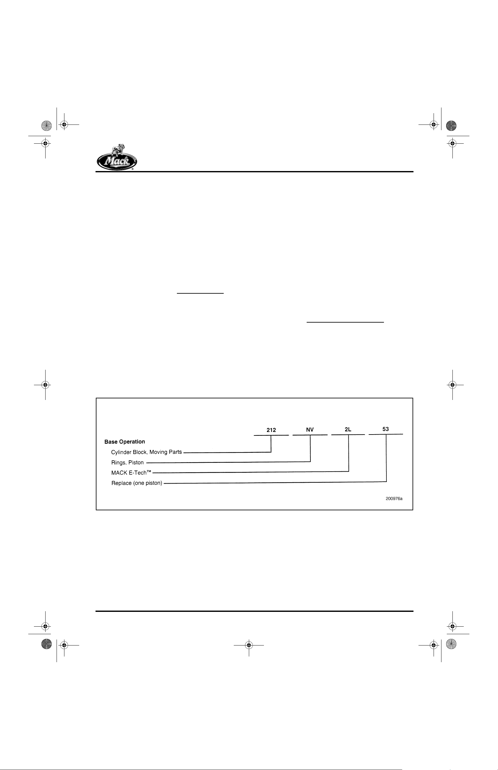
The system is based on a numerical code
first digit of which identifies the general
component grouping as listed here:
GROUP 000 — GENERAL DATA
GROUP 100 — CHASSIS
GROUP 200 — ENGINE
GROUP 300 — CLUTCH, TRANSMISSION,
TRANSFER CASE AND PTO
, the
GROUP 400 — STEERING, AXLES, WHEELS
AND TIRES, DRIVELINE
GROUP 500 — BRAKES, AUXILIARY
SYSTEMS
GROUP 600 — CAB, TRUCK BODY
GROUP 700 — ELECTRICAL
The second two digits of the three-digit code are
used to identify the system, assembly or
subassembly, as appropriate, within each of the
groupings. The codes applicable to this
publication are shown at the beginning of each
procedure, as necessary, to guide you to specific
component information.
Additionally, a two-character alpha code
[NV] RINGS, PISTON) may be referenced with
each procedure. This alpha code, in combination
with the three-digit Group number, identifies the
specific assembly, sub-assembly or part, and
directly relates to the fir st five positions of the
operation code listed in MACK Service Labor
Time Standards.
(i.e.,
Examples:
Numerical Code
Page 5
Page 22

5_106_00.bk Page 6 Friday, August 4, 2000 11:17 AM
INTRODUCTION
ABOUT THIS MANUAL
Changes from the Existing E-T ech™
Service Procedures Manual
Mack Trucks, In c. has made many major
improvements to this E-Tech™ Service
Procedures Manual, with changes to both content
and organization. This is a complete manual,
describing engine features and the operation of
major systems as well as providing
comprehensive overhaul procedures,
specifications and adjustments.
All specifications and torque values are given i n
English and metric measurements. Critic al torque
values are also included in the text, eliminating
the need to refer to SPECIFICATIONS section
each time a specified torque value is required.
The Special Tools list has been revised to include
all special tools requi red f or a c omplet e overhau l.
Warnings, cautions, notes and service hints help
the technician service the engine safely and
efficiently.
The engine disassembly procedures show how to
remove components in an order t hat requires the
least amount of handling. Where appropriate , it
includes general information needed to properly
service that component.
The engine reassembly procedure includes stepby-step instructions for reassembli ng the engine.
This helps to ensure proper installation and
longer service life.
Under Engine Setup and Adjustments, the latest
setup information is provided for adjust ing all
E-Tech™ engine models. Engines perform best
and conserve fuel most efficientl y when ad justed
properly.
Two addi tional procedures are included as guides
for removing and reinstalling the engine. Both
sections are generic in nature since E-Tech™
engine installation procedures vary from one
vehicle style to another. As such, the procedures
are intended as a checklist to remind the
technician of all necessary tasks.
While troubleshooting procedures are similar for
most diesel engines, this manual includes only
those that pertain to the E-Tech™ engine. The
TROUBLESHOOTING section contains
symptom-related questions as well as tests to
help the technician consider all possible problem
sources.
This service manual also includes applicable
information from active service bulletins and
service letters since publication of the E-Tech™
Service Procedures Manual dated July 1999.
Various component bench procedures guide the
technician in disassembly, cleaning, inspection
and assembly of each component. Each bench
procedure helps in determining if the part is
serviceable or should be replaced.
Page 6
Page 23

5_106_00.bk Page 7 Friday, August 4, 2000 11:17 AM
INTRODUCTION
ABOUT THE E-TECH™ ENGINE
AND ITS SERVICE
This publication is intended to provide technician s
with a working knowledge of the E-Tech™
engine, including both early-production and
current-production ver sions.
The E-Tech™ engine has undergone a left-side
redesign. Changes include a new plate-type oil
cooler and a new oil filter mounting arr angement.
This new oil filter arrangement includes a new
centrifugal oil filter assembly, where the
centrifugal filter assembly is now mounted upside
down, and the external oil drain is eliminated.
This new centrifugal oil filter is call ed Centri-Max
PLUS.
The engine electronic control unit (EECU) has
been relocated to the left side of the engine and
is mounted on a new one-piece inlet manifold.
Relocating the EECU has eliminated the need fo r
the EECU cooling plate, and has also brought
about a design change to the unit pump front
outboard heat shield. Additionally, with the
change to the one-piece inlet manifold, the fuel
filter mounting adapter is new and is located
slightly forward of the previous location.
Descriptions of these design changes and the
other features are provided in the DESCRIP TION
& OPERATION section. Additionally, the service
effects of these changes on removal, installation,
disassembly, assembly, setup and adjustment
procedures, etc., are included in the respective
sections of this publication.
®
Development of the E-Tech™ engine has been
driven by three basic requirements. It was
designed to:
r Meet projected exhaust and noise emissions
regulations.
r Meet customer demands for improved fuel
economy, driveability and engin e braki ng.
r Compete in a world market.
Although the drive to reduce emissions and noise
levels is primarily the result of gove rnment
mandates, the E-Tech™ engine is designed to
provide customers with an improved engine over
the existing E7 engine it replaces. Specific
improvements include:
r Improved fuel economy.
r Increased throttle response (time to
90 percent torque is faster with the
E-Tec h ™).
r More retarding horsepower through a newly
designed J-Tech™ Engine Brake from
Jacobs.
Mack Trucks, Inc . is looking beyond the borders
of North America to increas e its mar ket and br ing
the quality, toughness and technology associated
with the MACK name to a worldwide audience.
The current environment of global regulati ons
concerning exhaust emissions, noise and other
factors has leveled the playing field on an
international basis. This means that the
improvements made to meet the North American
environmental regulations can now be applied
worldwide.
The E-Tech™ engine is used in MACK trucks and
European Renault VI trucks.
Page 7
Page 24

5_106_00.bk Page 8 Friday, August 4, 2000 11:17 AM
NOTES
Page 8
Page 25

5_106_00.bk Page 9 Friday, August 4, 2000 11:17 AM
IDENTIFICATION
IDENTIFICATION
Page 9
Page 26

5_106_00.bk Page 10 Friday, August 4, 2000 11:17 AM
IDENTIFICATION
ENGINE MODEL
IDENTIFICATION
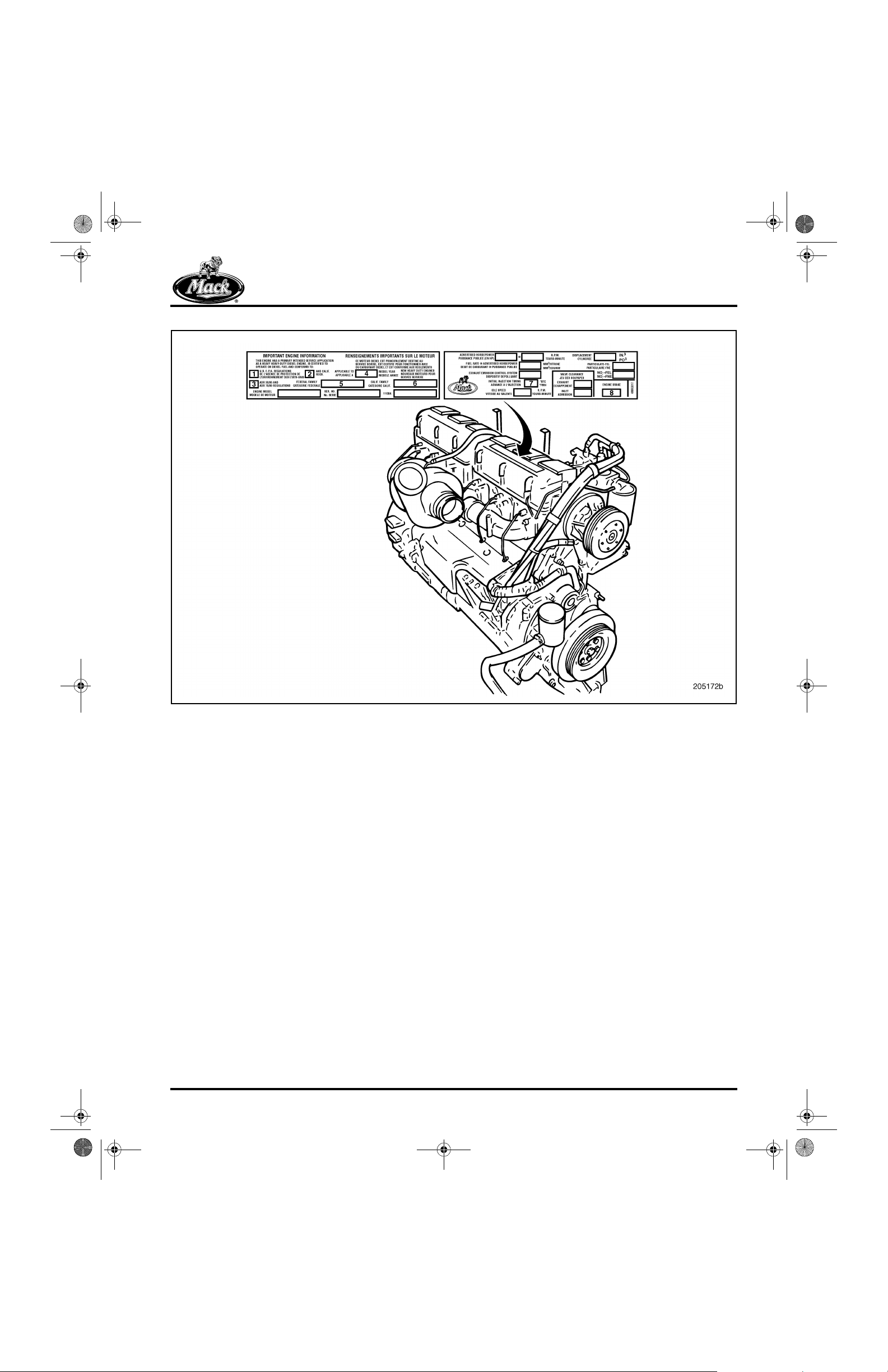
Engine Information Plate
The E-Tech™ engine information plate is located
on the top of the front cylinder head cover (back
cover for LE and MR chassis). This plate includes
information concerning:
r Engine model, serial number and 11GBA
part number.
r Advertised horsepower at rated speed rpm.
r Emissions regulations to which the engine
conforms and other pertinent information
required by emissions regulations.
r Inlet and exhaust valve lash settings and
engine brake slave piston lash setting.
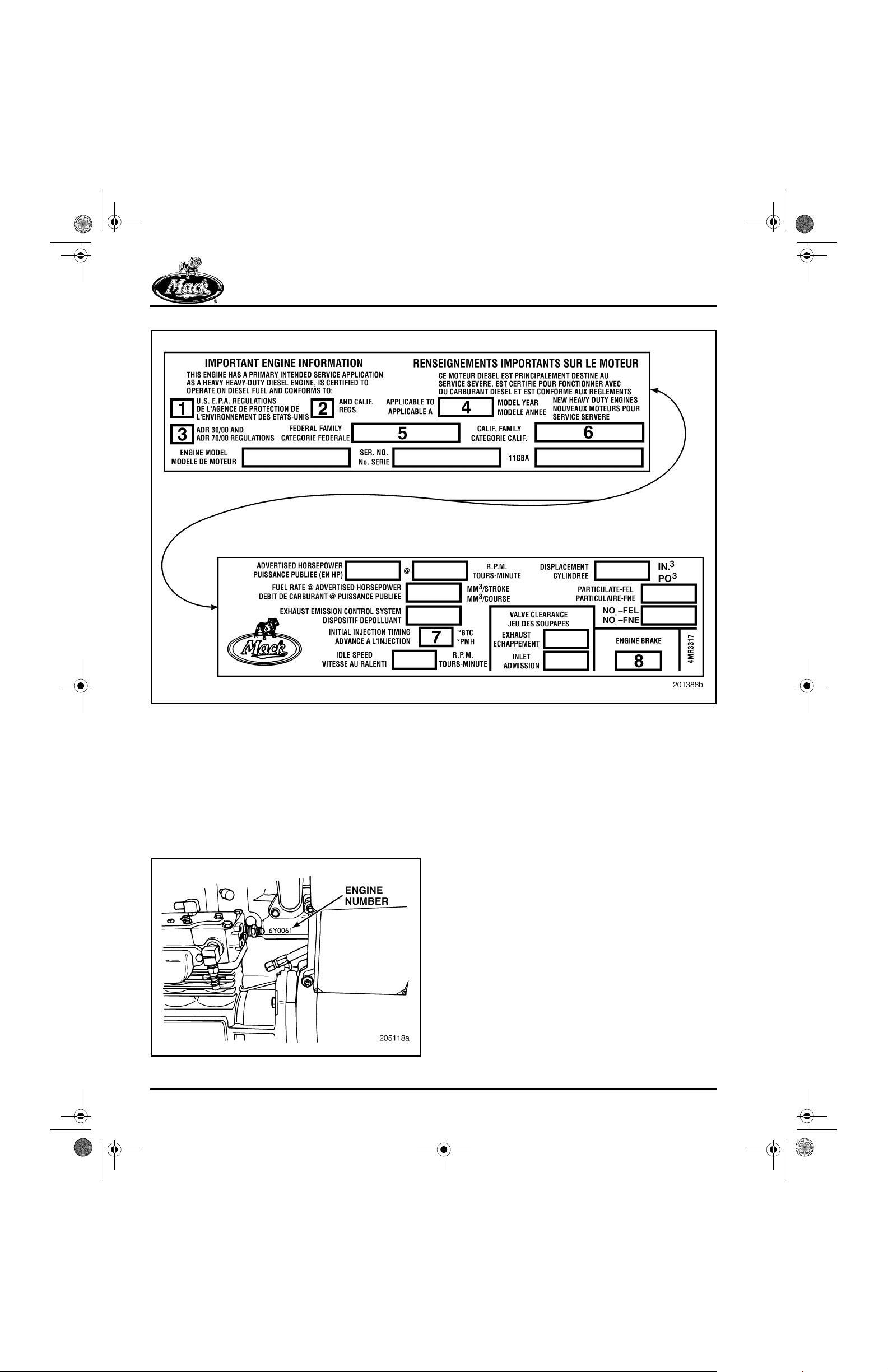
The following explanations are provided to aid in
interpreting some of the key information found on
the engine information plate.
Block 1 — U.S. EPA Regulations
r An “X” in block one means the eng ine meets
United States EPA regulations for the year
stamped in block four.
Block 3 — ADR Regulations
r An “X” in block three means the engine has
been certified to meet Australian emissions
regulations.
r Two dashes in block three mean the engine
does not meet Australian emissions
regulations.
Block 4 — Model Year
r The four-digit number stamped in block four
represents the year in which the engi ne was
certified.
Block 5 — Federal Family
r A 12-digit number stamped in block five
denotes the Federal Family to which the
engine belongs for emissions certification
purposes.
r All domestic engines will have a 12-digit
Federal Family number in block five.
Block 6 — California Family
r If the engine meets California emissions
regulations, the same 12-digit number
stamped in the Federal Family block is
stamped in block six.
r Two dashes in bl ock one indicate the engine
does not meet United States EPA
regulations for the year stamped in block
four. This is only permissible with certain
export engines. All domestic engines will
have an “X” in block one.
Block 2 — California Regulations
r An “X” in block two indicates the engine
meets California emissions regulations for
the year stamped in block four. This engine
is referred to as a “50-state” engine and can
be sold in any state throughout the U.S.
r Two dashes stamped in block two mean the
engine does not meet California emissions
regulations. If an engine has an “X” in block
one and two dashes in block two, it is
referred to as a “49-sta te” engine, meaning it
is not certified for sale in California.
r If the engine does not meet California
emissions regulations, there will be two
dashes in block six.
Block 7 — Initial Injection Timing
r E-Tech™ engines do not have an initial
injection timing, as this is controlled
electronically.
r E-Tech™ engines will have “NA” stamped in
block seven.
Block 8 — Engine Brake
r This block is only used when the engine is
equipped with an engine brake. The
stamping in this block indicates the engine
brake slave-piston lash setting.
Figure 1 illustrates the location of the information
plate and Figure 2 illustrates its content.
Page 10
Page 27
5_106_00.bk Page 11 Friday, August 4, 2000 11:17 AM
1
IDENTIFICATION
Figure 1 — Engine Information Plate Location
Page 11
Page 28
5_106_00.bk Page 12 Friday, August 4, 2000 11:17 AM
2
IDENTIFICATION
Figure 2 — Engine Information Plate
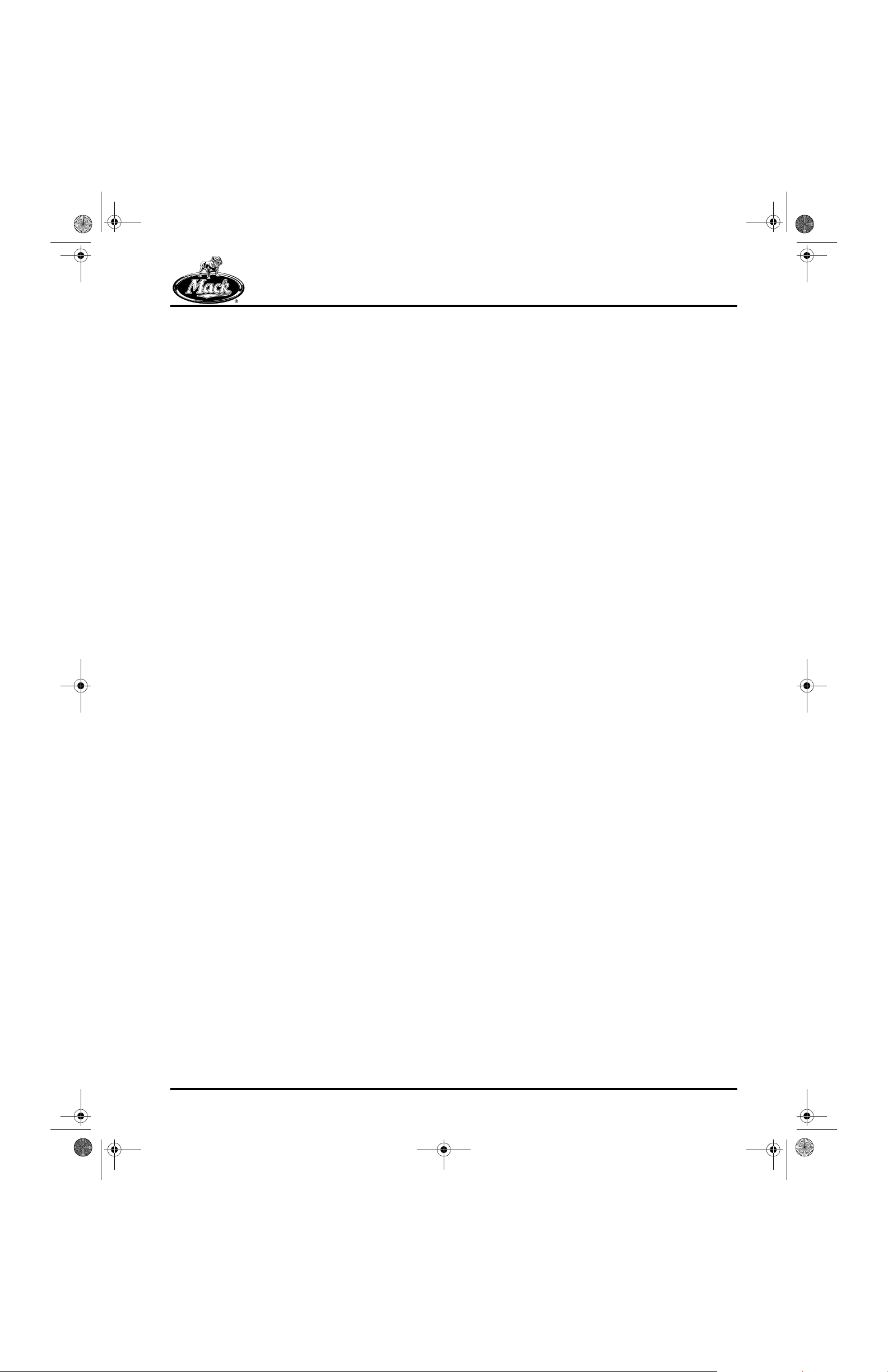
Engine Serial Number Identification
In addition to the engine information plate on the
front cylinder head cover, the engine is also
identified by the engine serial number stamped
into the cylinder block. This serial number is
located on the block right side just below the
turbo oil drain tube flange as shown in Figure 3.
3
Page 12
Figure 3 — Engine Serial Number
Page 29
5_106_00.bk Page 13 Friday, August 4, 2000 11:17 AM
DESCRIPTION & OPERATION
DESCRIPTION & OPERATION
Page 13
Page 30
5_106_00.bk Page 14 Friday, August 4, 2000 11:17 AM
DESCRIPTION & OPERATION
E-TECH™ ENGINE DESIGN
FEATURES
The E-Tech™ engine evolved from the E7 PLN
(commonly referred to as the E7). The four
primary design features that differentiate the
E-Tech™ engine from the E7 engine are as
follows:
r Electronic Unit Pump (EUP) fuel injection
system
®
r V-MAC
r Poly-v belt drive system
r J-Tech™ engine brake system from Jacobs
These major changes resulted in subsequent
improvements and redesign of related
components within the engine.
Electronic Unit Pumps
Electronic Unit Pump (EUP) technology, which
has been utilized in the heavy-duty industry for
many years, has been adapted for the E-Tech™
engine to achieve:
III electronic control system
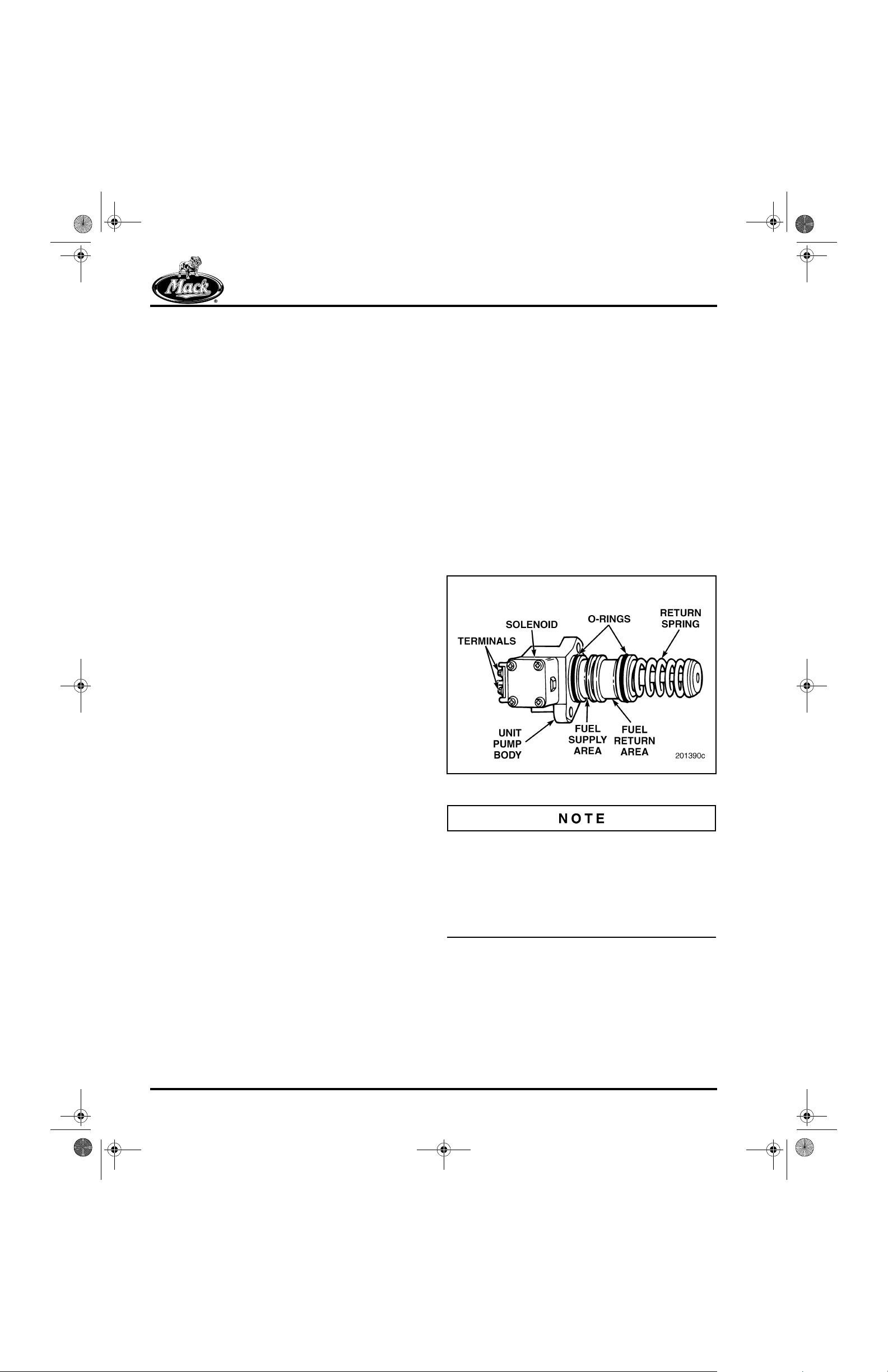
The EUP is very similar to a unit injector. The
primary difference is that the EUP delivers fuel
through a fuel injection line to a convent ionalstyle nozzle-holder assembly, whereas a unit
injector has a nozzle mounted directly on it.
The EUP is capable of providing very high fuelinjection pressures. The pump is controlled b y a
high-speed solenoid valve (see Figure 4)
responding to electronic signals from the
V-MAC III engine control module. This electronic
control provides a greater timing range. The
combination of higher pressures and greater
timing control improves the combustion process
and optimizes engine performance. This enables
the E-Tech™ engine to conform to more stringent
emissions regulations while providing
performance and fuel economy improvements.
4
r Optimum performance
r Lower emissions
r Simplified service
r More effective pump/engine diagnostics
(individual cylinders can be isolated)
An EUP is a single-plunger fuel-injection pump,
one per cylinder, driven by a third lobe on the
engine camshaft. The pump roller follower
(tappet) is in contact with the engine cam lobe.
Figure 4 — EUP Components
Electronic unit pumps for engines produced
through approximately late 3r d quarter 2000 were
fitted with three O-rings on the pump housings.
Pumps on engines produced later than 3rd
quarter 2000 are fitted with two O-rings in the top
and bottom grooves. The O-ring in the center
groove has been eliminated.
Page 14
Page 31

5_106_00.bk Page 15 Friday, August 4, 2000 11:17 AM
DESCRIPTION & OPERATION
The EUP design does not include a helix on the
pump plunger. Fuel delivery is controlled entirely
by the solenoid valve. To start fuel delivery, the
V- MAC III c ontrol syst em allows current to fl ow to
the solenoid, closing the solenoid valve and
trapping fuel in the pump. As the plunger moves
upward, fuel is delivered through the highpressure line to the fuel-inj ector nozzle assembly.
When current flow to the solenoid is stopped, the
solenoid valve opens and fuel in the pump then
flows to the cylinder block fuel return gallery.
Refer to Figure 5.
5
The EUP system, using proven industry
technology, is well adapted to troubleshooting.
When required, an individual EUP can be
replaced with a minimum of downtime.
Because the unit pumps are located in close
proximity to the exhaust manifold, heat shiel d s
have been added to prevent excessive heat from
reaching the EUP components.
The right-side heat shields on an E-Tech™
engine are a mandatory part of the engine
(Figure 6). The heat shields must
be reinstalled if
they are removed for mainten ance or repair .
Failure to do so will result in damage to the
sensitive electr onic components.
6
Figure 5 — Electronic Unit Pump
Current production E-Tech™ engines contain
EUPs with three O-rings. On future production
engines the center O-ring will be eliminated.
Present EUP service kits available through
MACK service parts do not contain the center
(brown) O-ring.
Figure 6 — Heat Shields (with Right-Side Mounted
EECU)
1. Heat Shield Attachment Points
Page 15
Page 32

5_106_00.bk Page 16 Friday, August 4, 2000 11:17 AM
DESCRIPTION & OPERATION
7
Figure 7 — Heat Shields (with Left-Side Mounted EECU)
1. Fuel Temperature Sensor 2. Redesigned Heat Shield
V-MAC III
The V-MAC II I engine control system has been
developed specifically for the E-Tech™ engine.
Features include electronic drivers and
diagnostics for unit pumps, separate engine and
vehicle control units, and a revised wiring
harness. These features make V-MAC III
applicable only to the E-Tech™ engine.
V-MAC III ELECTRONIC CONTROL UNITS
The Engine Electronic Control Unit (EECU) is
located on the right side of the engine (Figure 8)
in early-production engine s. Characteristics of the
engine design, such as heat shields, vibration
isolation, and running low-pressure fuel through
the EECU mounting plate (to cool it), permit the
EECU to be mounted directly on the engine in the
right-side location.
8
Page 16
Figure 8 — V-MAC III Engine EECU (Righ t-Side Mounte d)
Page 33

5_106_00.bk Page 17 Friday, August 4, 2000 11:17 AM
DESCRIPTION & OPERATION
For current-production engines, the EECU is
relocated to the left side of the engine (Figure 9)
and mounted on a new one-piece air inlet
manifold (Figure 13). With this relocation, the
fuel-cooled backing plate is no longer necessary
and has been eliminated. The new harness is
routed around the rear of the engine, and the
module and harness connections are mounted
vertically at the forward end of the module . This
provides an improved environment and less
chance for water infiltration at the harness
connectors.
9
With the two-module design, a more efficient and
reliable electronic communication network,
known as multiplexing, can be used. Mul ti plexing
essentially means that inputs and outputs to and
from one control unit are “batched” and sent as a
package to the other control unit via a single,
high-speed communication line. Inherent to this
system is a significant reducti on in the length and
number of wires, specifically those which must
pass through the bulkhead, as well as the rel ated
connections.
V- MAC III SYSTEM SENSORS
There are a total of eight engine-mounted
sensors and one vehicle-mounted sensor. Seven
of the sensors provide input for the operation of
the V- MAC III engine cont rol system, while the
remaining two sensors provide input for the dash
gauges. The dash gauge oil temperature sensor
is optional.
The following list and Figure 10 through Fi gure 19
identify the nine sensors and the features and
location of each. Three of the V-MAC III sensors
will be described in detail. These are the fuel
temperature sensor and the engine speed and
engine position sensors. The engine speed and
engine position sensors are functionally simila r to
the E7 RPM/TDC and TEM sensors, but are later
designs, quite different from the E7 sensors.
Figure 9 — EECU (Left-Side Mounted)
1. Engine ECU 2. Air Inlet Manifold
The cab-mounted V ehicle Electronic Control Unit
(VECU) provides a base for future development,
such as “total vehicle” systems and wireless
communication.
For enhanced quality, an engine-mounted EECU
allows the complete engine system (EECU,
harness and sensors) to be assembled at the
engine manufacturing/assembly plant, then
tested and verified on site. The entire engine
electronic package can be left undisturb ed during
the vehicle assembly process.
r Engine Speed Sensor
r Fuel Temperature Sensor
r Oil Pressure Sensor
r Ambient Air Temperature Sensor (see Note)
r Boost Air Temperature Sensor
r Dash Gauge Coolant Temperature Sensor
r V-MAC III Coolant Temperature Sensor
r Engine Position Sensor
r Dash Gauge Oil Temperature Sensor
(optional)
Page 17
Page 34

5_106_00.bk Page 18 Friday, August 4, 2000 11:17 AM
DESCRIPTION & OPERATION
The chassis-mounted ambient air temperature
sensor was not available with early-production
engines. It was phased into produc tion begi nning
approximately mid-July 1999 for CX model
chassis, mid-September 1999 for CH, CL, RD8,
MR, DM and DMM model chassis and early
November 1999 for RD6, RB and LE model
chassis. The sensor is mounted off-engine and
supplies temperature input to the engine
electronic control unit (EECU), so t hat the V -MAC
system can determine a mor e accurate i ndicati on
of inlet air temperature.
Location of the sensor depends upon chassis
model, but in general, it is located at the front of
the chassis mounted either on the front
crossmember behind the bumper, on a hood
hinge, hood hinge bracket, body, spring bracket,
or grille guard assembly.
10
Figure 10 — V-MAC III Engine-Mounted Sensor Locations (Pre-Left-Side Redesign)
1. Fuel Temperature Sensor (Behind Fittings)
2. Dash Gauge Coolant Temperature Sensor
3. V-MAC III Coolant Temperature Sensor
4. Boost Air Temperature Sensor
5. Engine Speed Sensor (on Left Side of Flywheel Housing)
Page 18
6. Dash Gauge Oil Temperature Sensor (on Left Side of Oil
Pan)
7. Oil Pressure Sensor
8. Engine Position Sensor (on Engine Front Cover)
Page 35

5_106_00.bk Page 19 Friday, August 4, 2000 11:17 AM
DESCRIPTION & OPERATION
11
Figure 11 — V-MAC III Engine-Mounted Sensor Locations (with Left-Side Mounted EECU)
1. Fuel Temperature Sensor (Behind Fittings)
2. Dash Gauge Coolant Temperature Sensor (on Side of
Coolant Manifold)
3. V-MAC III Co olant Temperature Sensor (on End of Coolant
Manifold)
4. Boost Temperature Sensor (on Top of Air Inlet Manifold)
On current-production engines with the left-side
mounted EECU, there are three harness
connectors adjacent to the oil pressure sensor.
One connector, the oil pressure sensor
connector, is always used. The other two
connectors are for an optional oil temperatur e
sensor. One connector (color-coded black) is for
the oil temperature sensor used with the standard
dashboard, and the other connect or (co lor-c oded
gray) is for the oil temperature sensor used with
the electronic dash. Oil temperature sensor part
No. 64MT2116 is used with the standard
dashboard and sensor part No. 64MT2103 is
used with the electronic dashboard.
5. Oil Temperature Sensor (on Filter Mounting Bracket)
6. Oil Pressure Sensor (on Filter Mounting Bracket)
7. Engine Speed Sensor
8. Dash Gauge Oil Temperature Sensor
9. Engine Position Sensor (on Engine Front Cover)
12
Figure 12 — V-MAC III Sensor Locations at Filter
Mounting Bracket (with Left-Side Mounted EECU)
1. Oil Temperature Sensor
2. Oil Pressure Sensor
3. Filter Mounting Bracket
Page 19
Page 36

5_106_00.bk Page 20 Friday, August 4, 2000 11:17 AM
DESCRIPTION & OPERATION
On current-production engines with the left-side
mounted EECU, the boost temperature sensor
port has been moved to the manifold inlet area
(depending upon chassis model, the manifold
inlet is at the front, or the center) . There is a large
boss at the rear of the manifold for boost air
supply to the air compressor and boost pressure
access ports.
13
Figure 13 — V-MAC III Sensor Locations with Front Air Inlet Manifold (Left-Side Mounted EECU)
1. Boost Temperature Sensor
2. Fuel Filter Mounting Bracket Boss
3. Port for Boost Pressure Test Gauge
4. Boost Pressure Port for Line-to-Dash Gauge or Boost
Pressure Sensor
5. Boost Air Supply to Air Compressor
6. Engine Electronic Con trol Unit Isolator Mounting Stud,
Threaded Bosses
Page 20
Page 37

5_106_00.bk Page 21 Friday, August 4, 2000 11:17 AM
DESCRIPTION & OPERATION
14
Figure 14 — V-MAC Sensor Locations with Center Air Inlet Manifold (Left-Side Mounted EECU)
A. Side View
B. Top View
1. Fuel Filter Mounting Bracket Boss
2. Port for Boost Pressure Test Gauge
3. Boost Temperature Sensor
An interim version front manifold was used on
engines with the new oil cooler/filter arrangement,
but without the engine ECU relocation.
4. Boost Pressure Port for Line-to-Dash Gauge or Boost
Pressure Sensor
5. Boost Air Supply to Air Compressor
6. Engine Electronic Con trol Unit Isolator Mounting Stud,
Threaded Bosses
The V-MAC II I sensors have different mounting
methods, or mounting threads, compared to the
similar V-MAC
®
II sensors:
r V- MAC III engine speed a nd engine po sit ion
sensors are flange-mounted with a mounting
screw .
r V-MAC III oil pressure, boost temperature,
fuel temperature and coolant temperature
sensors have English pipe threads.
r Dash gauge sensors for coolant and oil
temperatures are threaded sensors with
English pipe threads, the same as the E7
with V-MAC II.
Page 21
Page 38

5_106_00.bk Page 22 Friday, August 4, 2000 11:17 AM
DESCRIPTION & OPERATION
Fuel Temperature Sensor
On early-production engines with a right- side
mounted EECU, a fuel temperature sensor is
provided at the top of the secondary fuel filter
mounting adapter (Figure 15) installed in a boss
adjacent to the outlet fitting. The V-MAC III
system monitors fuel temperature at the
secondary fuel filter outlet, as fuel is being
supplied to the cylinder block fuel gallery inlet.
This fuel temperature data improves accuracy of
the mpg fuel consumption information shown on
®
the Co-Pilot
display.
The fuel temperature sensor is the same as the
coolant temperature sensor used at the rear of
the water manifold location. The illustration that
follows shows a CH/CL/DM engine-mounted, fu el
filter adapter. The RD/MR/LE chassis-mounted
secondary fuel filter mounting adapter has a
similar sensor mounting boss. In either case, if
the fuel temperature sensor is not used, the boss
should not be drilled and tapped.
15
On current-production engines with the left-side
mounted EECU, the fuel temperature sensor is
located at the fuel cylinder block fu el gallery inlet
(Figure 16). This location is standardized for all
fuel filter arrangements, simplifying and
improving the line routing.
16
Figure 15 — Fuel Temperature Sensor (Engine with
Right-Side Mounted EECU)
Figure 16 — Fuel Temperature Sensor (Engine with
Left-Side Mounted EECU)
1. Fuel Temperature Sensor 2. EUP Heat Shield
Page 22
Page 39

5_106_00.bk Page 23 Friday, August 4, 2000 11:17 AM
DESCRIPTION & OPERATION
Engine Speed Sensor
This sensor is located at the left side of the
engine flywheel housing (Figure 17). It is flan gemounted and held in place by a retaining screw.
The engine speed sensor is the same part
number as the engine position sensor,
located on the engine front cover.
17
Figure 17 — Engine Speed Sensor
18
Figure 18 — Engine Position Sensor
Boost Temperature Sensor and Boost
Pressure Diagnostic Ports
A V-MAC III boost temperature sensor is located
on the top of the rear inlet manifold (Figure 19).
There is no boost pressure sensor because, as
with all V-MAC systems, V-MAC III uses ECU
programming for transient smoke control.
The E-Tech™ flywheel has 117 teeth (one less
tooth than the E7 engine flywheel) and has two
adjacent teeth with part of their width (1/4 inch)
machined off. These two teeth on the E-Tech™
flywheel allow the sensor to determine top dead
center (TDC) of cylinder Nos. 1 and 6, whereas
sensing notches are used on the front face of the
E7 flywheel. Because of this feature, ring gear-toflywheel indexing must be maintained.
Engine Position Sensor
The engine position sensor is located on the
engine front cover (Figure 18) and is retained in
the same manner as the engine speed sensor.
This sensor is designed to monitor the passage of
holes which are in the front face of the camshaft
timing gear . This sensor performs a function
similar to the TEM sensor in the Bosch Injection
Pump RE30 governor on the E7 engine.
There are two boost pressure gauge ports just
forward of the boost temperature sensor. The
forward port is used for the dash boost pressure
gauge when chassis is so equipped. The port
adjacent to the boost temperature sensor can be
used to install a boost pressure gauge for
diagnostic purposes if the need arises.
19
Figure 19 — Boost Temperature Sensor and Boost
Pressure Gauge Ports
Page 23
Page 40

5_106_00.bk Page 24 Friday, August 4, 2000 11:17 AM
DESCRIPTION & OPERATION
Belt Drive System
The belt drive system uses a single 10-ri b po ly-v
belt to drive the alternator, water pump, and fan
drive (Figure 20). A separate single-v bel t,
running off the water pump pulley, drives the
refrigerant compressor. The service life of the
poly-v belt is considerably improved over other
systems and allows the use of hi gher horsepower
cooling fans.
Both manually tensioned and automatically
tensioned systems are used. Whether an engine
has the manually tensioned or automatically
tensioned system depends on the spec ific engine
configuration and application.
20
J-Tech™ Engine Brake
The J-Tech™ engine brake is a vehicle-slowing
device that allows the engine to act as an air
compressor , producing retarding horsepower that
helps slow the vehicle. The braking action is
accomplished through hydraulics using a masterslave piston arrangement similar to a hydraulic
jack. When the engine brake is operat ed, a single
exhaust valve opens near top dead center of the
compression stroke, releasing high-pressure air
out the exhaust. Opening one exhaust valve,
instead of two, significantly reduces load to the
engine brake and the valve train without
adversely affecting braking power . Releasing
compressed air to the exhaust prevents the
return of energy to the engine piston on the
expansion stroke. The result is a net power loss
from the engine, or ret arding horsepower, used to
slow the vehicle.
With the J-Tech™ engine brake unit, the master
piston of a given cylinder activates the slave
piston of that same cylinder, providing optimum
timing of the compression release. The E- Tech™
engine uses the same engine brake unit on the
front and rear cylinder head.
1. Air Conditioner
Compressor
2. Water Pump
Page 24
Figure 20 — Belt Drive
3. Alternator
4. Poly-V Belt
5. Tensioning Device
Page 41

5_106_00.bk Page 25 Friday, August 4, 2000 11:17 AM
DESCRIPTION & OPERATION
ENGINE BRAKE FEAT URES
Refer to Figure 22.
There are major valve train changes relative to
engine brake implementation on the E-Tech™
engine. The most evident changes include:
r A significantly larger brake unit with a
different appearance and operat ing concept
than the E7.
r Standard E-Tech™ valve yokes are used at
all positions. The special Jacobs exhaust
yokes on the E7 engine are not used. Note
that the E-Tech™ engine uses a different
valve yoke from the E7 engine. The E7 and
E-Tech™ yokes are not interchangeable.
r A hollow yoke adjusting screw with a floating
pin in the screw is used in the exhaust
yokes. The screw opens only the exhaust
valve directly beneath it when the
J-Tech™ engine brake is activated.
r Unique exhaust rocker arm adjus ting screws
and nuts (Figure 21).
21
Figure 21 — Rocker Arm Adjusting Screws and Nuts
22
Figure 22 — J-Tech™ Brake Valve Yoke Hollow Adjusting Screw Arrangement
Page 25
Page 42

5_106_00.bk Page 26 Friday, August 4, 2000 11:17 AM
DESCRIPTION & OPERATION
ENGINE BRAKE OPERATION
Refer to Figure 23.
The J-Tech™ brake functions in the following
manner:
r Under powered operation, a large lash in the
valve train “skips” the 0.100-inch brake
bump on the camshaft.
r During engine brake operation, the solenoid
valve is energized, allowing engine oil to fill
the J-Tech™ brake housing oil passages.
r Oil overcomes the control valve spring and
drives the control valve up in its bore. Oil
passes through the ball check inside the
control valve and exits through the port in
the side, filling the master/slave piston
circuit.
To help prevent breaking or dislodging of the
control valve snap ring, the J-Tech™ control
valve components have been redesigned to
incorporate a new-style collar ( which replaces the
old-style valve stop spacer) and outer spring and
a retaining washer. With this change, the part
number of the engine brake housing assembly
was changed from 757GB58B to 757GB58C
(beginning with housing assembly Serial No.
D69006001), and was phased into E-Tech™
engine production June 30, 1999 (beginning with
engine serial number 9M4395).
23
r Oil pressure causes the master piston and
rocker arm to move down, removing the
large lash from the cam side of the valve
train. The result is a corresponding lash
increase on the exhaust valve side.
r The brake bump on the exhaust cam forces
the master piston upward and directs highpressure oil to the slave piston. The check
valve in the control valve prevents highpressure oil from escaping.
r High-pressure oil causes the slave piston to
move down, opening the outboard exhaust
valve via a valve-actuating pin which passes
through the center of the yoke adjusting
screw. Activation occurs near top dead
center and releases co mpressed air into the
exhaust manifold.
r At stroke bottom, the slave piston separates
from the reset valve, allowing oil to flow into
the accumulator. This action reduces
pressure in the high-pressure circuit,
permitting the slave piston to retract and the
exhaust valve to close in preparation for
normal exhaust cycle. Oil in the accumulato r
ensures the hydraulic circuit is fully charged
for the next cycle.
Figure 23 — J-Tech™ Brake
Page 26
Page 43

5_106_00.bk Page 27 Friday, August 4, 2000 11:17 AM
DESCRIPTION & OPERATION
Camshaft
The large diameter of the camshaft (Figure 24)
provides the strength necessar y for actuating the
unit pumps. In addition to the inlet and exhaust
valve lobes, lobes have been added to drive the
unit pumps. The camshaft also has more
aggressive intake and exhaust cam profiles for
improved fuel economy and emissions. A bump
in the exhaust cam profile provides timing for
engine brake operation.
The camshaft has induction-hardened journals
and lobes. This process produces a pronounced
heat discoloration mark approximately 3/8-inch
wide, around the front and rear faces of each
journal and lobe.
As an additional aid in reducing cam bushing
temperature, a groove has been added to the No.
4 journal of current-production camshaf ts. This
groove was not included on early-production
units. Adding the groove to the camshaft journal
has not resulted in a change to the camshaft part
number .
24
Valve Train
The valve train accommodates the aggressive
cam profiles. Roller lifters and roller followers or
“tappets” (Figure 25) are used to actuate the
valves and unit pumps, respectively. The roller
lifters handle aggressive cam profiles better and
have increased load-carrying capability.
25
Figure 25 — Roller Lifters
Figure 24 — Camshaft
VALVES
The stem tip of the valve has grooves to identify
the valve as intake or exhaust. The exhaust seat
face is 30 degrees, whereas the i nlet valve seat is
20 degrees.
Page 27
Page 44

5_106_00.bk Page 28 Friday, August 4, 2000 11:17 AM
DESCRIPTION & OPERATION
VALVE SEALS
The engines are produced with a v alv e stem seal
that features a multi-lip upper section, combined
with a second lip to significantly reduce
crankcase blow-by. This seal can easily be
identified by the steel retainer band around the
top of the seal lip.
To improve seal-to-guide retention, the guides
have three sharp ridges machined into the upper
outside diameter surface. Refer to Fig ure 26.
26
YOKES
Pin-Type Yokes
During February of 1999, the welded wear padstyle yoke was supplemented in product ion with a
headed pin (“button”) type yoke. The material of
the pin-type yoke remains ductile iron.
Both the new configuration and the previous
configuration valve yokes are being used in
current E-Tech™ engine production, but the
yokes will not be intermixed on the same engine.
27
Figure 26 — Valve Seal
VALVE SPRINGS, ROTATORS AND
PUSH RODS
E-Tech™ valve springs and rotators have heavier
spring tension (pressure) than the E7 to
accommodate the more aggressive cam profiles.
Push rod design also incorporates a larger
diameter to handle the increased loads.
Page 28
Figure 27 — Current Valve Yokes
For service purposes, it is acceptable to intermix
the different configuration yokes on the same
engine.
Page 45

5_106_00.bk Page 29 Friday, August 4, 2000 11:17 AM
DESCRIPTION & OPERATION
On E-Tech™ and E7 engines, the valve yokes
are very similar . However , it extr emely critical that
the correct valve yokes are used with the correct
engine. The previous configuration yokes were
identified with the letter “M” or “E” cast in to the top
of the yoke next to the slipper pad wear area. The
letter “M” signifies the valve yoke is used in E7
engines, and the letter “E” signifies that the yoke
is used in E-Tech™ engines. On the new “buttonhead” style valve yoke, however, the letters “M”
and “E” have been eliminated. Additionally, the
yokes no longer have part numbers stamped on
them. Installation of the correct new butt on-head
style valve yokes on the correct engine is still
critical. Therefore, a means of positively
differentiating between E-Tech™ and E7 is
provided in the following information and
illustrations.
The most positive means of identification are by
looking at the nose of the valve yoke. The
E-Tech™ yoke has the nose end of the slipper
pad area ground flat as shown in Figure 28.
28
29
Figure 29 — Valve Yoke Side View
Figure 28 — E-Tech™, E6, E7 and E9 Valve Yokes (Top
View)
A second method of identifying the “button-head”
yoke is to look at the side view. On the yoke used
for the E-Tech™ engine, the top surface of the
adjusting screw end is on the same plane as the
bottom surface of the “button-head.” On the E6,
E7 and E9 valve yokes, the top surface of the
adjusting screw area is 0.145 inch below the
bottom surface of the “button-head.” Refer to
Figure 29 for an illustration of these differences.
The yokes used on the E-Tech™ engine have a
deeper engagement at yoke screw end than E7
because of the longer valve (Figure 30). E7 and
E-Tech™ yokes are very similar in appearance,
but should not be interchanged.
30
Figure 30 — Valve Yokes
1. E-Tech™ 2. E7
Page 29
Page 46

5_106_00.bk Page 30 Friday, August 4, 2000 11:17 AM
DESCRIPTION & OPERATION
Do not interchange yokes. If an E-Tech™ yoke is
used on an earlier E7 engine, the valve keepers
will become dislodged and cause a dropped
valv e. This will cause severe engine damage. If
the E7 yoke is used on an exhaust location of a
J-Tech™ brake-equipped E-Tech™ engine, the
yoke will disengag e from the valv e stem tip during
engine brake operation. See Figure 31.
31
1. Correct E7 Yoke/Valve Combination
2. Correct E-Tech™ Yoke/Valve Combination
3. E7 Yoke with E-Tech™ Valve
Page 30
Figure 31 — Yoke/Valve Combinations
4. E-Tech™ Yoke with E7 Valve
Note: Arrows identify problem areas.
Page 47

5_106_00.bk Page 31 Friday, August 4, 2000 11:17 AM
DESCRIPTION & OPERATION
Pinless Valve Yokes — Inlet Valve Locations
Beginning on March 2, 2000 (engine serial
No. 0D0120), pinless valve yokes were
implemented into production on all E-Tech™
engines. The pinless yokes are used for the inlet
valve only. This change also affects the cylinder
heads which no longer have yoke guide pins at
the inlet valve locations.
The pinless yoke is self-leveling in operati on and
does not have a yoke leveling adjustment screw.
Inlet valve lash adjustments are performed in the
normal manner with the rocker arm adjusting
screw . For the ex haust v alv es, it is st ill necessa ry
to adjust the valve yoke first, then the rocker arm
lash.
The bottom of the valve yoke that bridges the t wo
inlet valves has a round hole and an elongated
hole that fit over the valve stems. The nose of the
yoke with the elongated hole has two notches in
the casting. When installing the pinless yokes, it
is important that the end of the yoke with the two
notches faces away from the valve rocker shaft. If
the yoke is installed incorrectly, the yoke will
contact the rocker arm.
32
Figure 32 — Proper Assembly of the Pinless Valve Yoke
Page 31
Page 48

5_106_00.bk Page 32 Friday, August 4, 2000 11:17 AM
DESCRIPTION & OPERATION
ROCKER ARMS
Early-production E-Tech™ used the older-style
E7 rocker arms. Effec tive s econd quarter 1997, a
newly designed rocker arm (Figure 33) on which
the slipper-end wear surface is a hardened,
headed pin pressed into the rocker arm, was
introduced and is currently used.
33
Low-Pressure Fuel System
The flow of fuel through the low-pressure si de of
the fuel system is essentially the same as that in
the E7 engine for current-p roduction engines with
the left-side mounted EECU. However, on earlyproduction engines with the right-side mounted
EECU, a cooling plate was added to the circuit
(Figure 34).
Fuel flows from the fuel tank to the primary filter,
the EECU cooling plate (if equipped), the supply
pump, the secondary filter and the unit pumps.
Unused fuel is collected in the fuel return gallery
in the cylinder block and returned to the fuel tank
by a fuel return line.
To decrease restriction in the low-pressure fuel
system, hoses and fittings with larger inside
diameters are used for all suction lines in th e
E-Tech™ system.
To meet unit pump demands, the supply pump
provides a 100 gph fuel flow at 70 psi pressure.
This high level of flow and pressure is needed to
cool the unit pumps and EECU, and keep the fuel
supply gallery filled. A check valve fitting, located
on the fuel return gallery outlet on the cylinder
block right side, maintains fuel gallery pressure
and prevents the system from bleeding down
when the engine is not operating.
Figure 33 — New-Style Rocker Arm
ROCKER ARM/SHAFT ASSEMBLY
Improved features of the E-Tech™ rocker arm/
shaft assemblies include:
r No coil springs between rocker arms
r C-clips used to retain rocker arms
r Longer shaft lengths
r Cup plugs in shaft ends
r Improved centering of rocker arm slipper
feet over yoke pads
Page 32
On current-production engine s, a new fuel gallery
pressure regulating valve with a 70 psi spring
setting is used to reduce fuel gallery pressure and
fuel dilution.
The gear-type supply pump is located on the r ear
side of the right-front flange of the cylinder block.
It is driven by the engine camshaft gear. A hand
primer pump is mounted on the supply pump.
Page 49

5_106_00.bk Page 33 Friday, August 4, 2000 11:17 AM
DESCRIPTION & OPERATION
34
Figure 34 — Low-Pressure Fuel System
Page 33
Page 50

5_106_00.bk Page 34 Friday, August 4, 2000 11:17 AM
DESCRIPTION & OPERATION
Fuel Filtration System
To build up the extremely high pressures requi red
for improved combustion, unit pumps must have
an unrestricted supply of clean fuel. The
E-Tech™ filtration system, which utilizes a
primary and secondary filter element, was
designed to provide optimum balance between
filtration effici ency (micron size) and filt er change
interval (restriction).
The main design features of the E-Tech™
filtration system include:
r Fine micron media
r Large diameter seal surface on both filters,
as well as different primary and secondary
thread sizes (to avoid mix-up with E7 filters)
r Unique identification system (a red primary
filter and green secondary filter with black
logo and lettering, and two 1/4-inch black
bands, four inches fr om top of filter ). Refer to
Figure 35.
The fuel filter mounting adapter is made from a
casting, on which the primary and secondary
mounting flanges are the same large size
(Figure 36). The adapter has metr ic thread sp uds
for mounting the fuel filters. As has always been
the practice, primary and secondary spuds are
different sizes, so only the correct filter can be
installed at the proper location.
The correct fuel filter mounting adapter must be
used on the proper engine (E-Tech™ or E7) to
ensure the correct filters are used.
36
It is mandatory to use these improved fuel filters
on E-Tech™ engines to protect the unit pumps
from contaminant damage to the very closetoleranced internal components.
35
Figure 35 — Fuel Filters
Figure 36 — Fuel Filter Mounting Adapter (with
Right-Side Mounted EECU)
V-MAC III monitors fuel temperature at the
secondary fuel filter outlet which suppli es fuel to
the gallery feeding the unit pumps (early
production), or at the cylinder block fuel gallery
inlet (current production). This fuel temperature
data is used by the system to adjust fuel delivery
for optimized power and to provide accurate mpg
fuel consumption information shown on the
Co-Pilot display.
Page 34
Page 51

5_106_00.bk Page 35 Friday, August 4, 2000 11:17 AM
DESCRIPTION & OPERATION
High-Pressure Fuel System
The high-pressure fuel system (Figure 37) is
designed to provide fuel to the combustion
chamber under high pr essure. In thi s system, u nit
pumps (one per cylinder) replace the previo usly
used fuel injection pump. The unit pump
operating pressures are 26,000 psi, more than
50 percent greater than the peak injection
pressures of the E7 engine. These higher
pressures, along with an extended timing range
and optimized timing control, provide
performance improvements.
Fuel is supplied to each of the unit pumps by the
fuel supply gallery in the cylinder block. The high
pressure required for fuel injecti on is generated
by a pump plunger (10 mm diameter , 18 mm
stroke), which is act uated by a roll er cam f ollower
(tappet) driven by the engine camshaft. The
volume of fuel delivered to each cylinder is
precisely metered by a solenoid mounted on
each of the unit pumps, which responds to
signals from the V-MAC III EECU. The
pressurized fuel is delivered to the inject or
nozzles by individual fuel injector l ines, which are
the same for all cylinders and all E-Tech™ engine
models.
37
Figure 37 — High-Pressure Fuel System
Page 35
Page 52

5_106_00.bk Page 36 Friday, August 4, 2000 11:17 AM
DESCRIPTION & OPERATION
High-Pressure Fuel Injection Lines
High-pressure fuel lines for each cyli nder
(Figure 38) are short (17 inches) and have the
same bends and the strength to withstand the
high fuel pressure generated by electronic unit
pumps. The same part number is used for all
cylinders and all
engine models. Also, there are
no clamps used on these lines.
38
Figure 38 — Fuel Injection Lines
A check valve is incorporated in the nozzle
holders on current-production engines.
39
Fuel Injector Assemblies
Injector nozzles in the E-Tech™ differ from those
used in the E7 in that they have increased
material strength, a larger 22- mm dia meter and a
higher pressure capability. These features are
essentially due to the higher operating pressures
generated by the unit pumps.
In the E-Tech™ engine, a pin on the nozzle
holder locates the nozzle in the cylinder head.
The locating pin is on the same side as the nozzle
holder fuel inlet port. Refer to Figure 39.
Figure 39 — Fuel Injector Nozzle Holder
Page 36
Page 53

5_106_00.bk Page 37 Friday, August 4, 2000 11:17 AM
DESCRIPTION & OPERATION
Cylinder Block
The cylinder block is a single-piece design made
of high-strength alloyed gray cast iron. The deep
skirt extends well below the crankshaft center line
and incorporates seven main bearings. The
bearing caps are made of ductile iron and use
buttress screws at the intermediate locations.
Replaceable wet-dry sleeves line the cylinder
bore.
Due to the large camshaf t diameter, the cam bore
position is shifted up and outboard to operat e the
unit pumps and provide cam-to-crank clearance
(Figure 40). To accommodate this change in cam
position, the push rod holes are angled four
degrees and the air compressor angled out board.
The crank and cam timing gears do not mesh
directly, but power transmission occurs through
an idler gear mounted in an idler gear bore in the
front face of the cylinder block. The right-f ront
flange on the cylinder block provides a mounting
surface for the fuel supply pump.
40
Figure 40 — Cylinder Block
Page 37
Page 54

5_106_00.bk Page 38 Friday, August 4, 2000 11:17 AM
DESCRIPTION & OPERATION
The main oil gallery runs along the left side of the
block. A second oil gallery — the valve lif ter /EUP
oil supply gallery — runs along the right side of
the block. The valve lifter bores directly intersect
this right-side gallery, while oil is supplied to the
EUP by six passages drilled from the block’ s right
side, through the EUP bore an d into the adjacent
valve lifter bore. The six holes along the block’s
right side are closed off with pipe plugs.
Both the left- and righ t-side oil galleries are drilled
from the front and the rear , but do not meet at the
center. Oil is supplied to the valve lifter /EUP oil
gallery through drilled passages from the No. 2
and No. 5 cam bushings. An annulus i n No. 2 and
No. 5 main bearing bores, as well as the groove
in the upper bearing inserts, ensures a high
volume of oil to the lifter/EUP gallery.
Internal fuel supply and return galleries for the
unit pumps are gun-drilled axially, the full length
of the block’s right side just below the unit pump
mounting flange surface.
Current-production cylinder bloc ks were changed
to accommodate a redesigned oil cooler/filter
mounting arrangement. Early-production engi nes
used an externally drained Centri-Max
®
filter.
This arrangement has been replaced by the
internally drained Centri-Max PLUS filter on
current-production engi nes. The major change to
the cylinder block is in the four-bolt oil filt er
pedestal mounting pad located at the center lef thand side of the block. With the elimination of the
®
externally drained Centri-Max
filter, two internal
drain holes are now cast into this mounting pad.
These drain holes allow the Centri-Max
®
PLUS
drain oil to pass directly into the crankcase. The
two 3/4-inch “as-cast” holes are visible inside the
crankcase on either side of the No. 4 main
bearing bulkhead, between Nos. 3 and 4 piston
cooling nozzles. The external oil drain port in the
cylinder block used for the externally drained
Centri-Max
®
filter is covered with a block-off
plate.
Page 38
Page 55

5_106_00.bk Page 39 Friday, August 4, 2000 11:17 AM
DESCRIPTION & OPERATION
41
Figure 41 — Oil Filter Pedestal Mounting Pad and External Oil Drain Block-Off Plate
1. Oil Passage — Oil Pump-to-Oil Cooler and Filters
2. Intern al Drain Holes
The new internally drained Centri-Max® PLUS
filter requires the two internal drain cavities in the
cylinder block. The same cylinder blocks,
however , are used to service engines having
either the externally drained Centri-Max
internally drained Centri-Max
®
PLUS filter
®
, or the
assemblies. When a block is used for an engine
equipped with the externally drained Centri-Max
filter, the oil drain cavities are not functi onal.
3. External Oil Drain Block-Off Plate
Page 39
Page 56

5_106_00.bk Page 40 Friday, August 4, 2000 11:17 AM
DESCRIPTION & OPERATION
Crankshaft
The crankshaft is fully counterbalanced and has
induction hardened journals. There are seven
main bearings with thrust washers located at the
center main bearing (position No. 4) to absorb
fore and aft end thrust. Crankshaft extension at
the forward end carries the main drive gear,
vibration damper and accessory drive pulleys.
The main drive gear has a shrink fit and the
vibration damper hub has a press fit. The main
drive gear is keyed to the crankshaft for proper
assembly and engine timing. The flywheel is
mounted to a flange at the rear of the crankshaft.
Two seals, one at the front and one at the rear,
prevent engine lubricating oi l from leaking ar ound
the ends of the crankshaft.
Bearing caps are furnished with the crankcase
and support the crankshaft in true alignment.
Webs integral to th e crankcase provide the upper
half of the main bearing supports. Removable
caps provide the lower support and are held in
position with capscrews. The bearing caps are
not interchangeable and each has a number
stamped on it which signifies its correct location
and alignment in the crankcase. The caps are
numbered 1 through 7, with the No. 1 main
bearing cap at the front of the engine. The
bearing inserts are precision-designed, and are
positioned between the crankshaft and
crankcase, and between the crankshaft and the
bearing caps. Thrust flanges to support t he thrust
washers are located at the center main bearing
(No. 4).
Block Heater for Front (Water
Pump) Location
The engine accepts a straight element unit in the
rear location. Front installations require a curvedelement heater (Figure 42). This curved element
is located inside the lower par t of t he water pump
housing, which has been revised to
accommodate it. With factory installati ons, CH/CL
models use the rear location, while RD, MR and
other Macungie-built models use the front
location.
42
Figure 42 — Straight and Curved Block Heaters
Page 40
Page 57

5_106_00.bk Page 41 Friday, August 4, 2000 11:17 AM
DESCRIPTION & OPERATION
Cylinder Head
The cast iron cylinder head (Figure 43) is
constructed using a special iron alloy. The head
contains cored inlet, exhaust and coolant
passages, drilled oil passages, replaceable inlet
and exhaust guides and seats, various drilled
passages and tapped holes. Each cylinder head
covers three cylinders and has two inlet and two
exhaust valves per cylinder. Circular grooves
correspond with the fire ri ng bead on the cylinder
sleeves. This design sets the fire ring over the
liner. With the cylinder head installed and the
bolts tightened to specification, the l iner coining
bead extrudes the fire ring into the cylinder head
groove, providing a positi ve combustion pr essure
seal.
43
Figure 43 — E-Tech™ Cylinder Head
Page 41
Page 58

5_106_00.bk Page 42 Friday, August 4, 2000 11:17 AM
DESCRIPTION & OPERATION
Some characteristics of the E-Tech™ cylinder
head are not visually evident, but are still
significant (Figure 44). The y in clu de the fo llowing
listed items:
r Push rod holes are angled at four degrees
due to outboard location of camshaft.
r Large nozzle sleeve diameter to
accommodate 22-mm nozzle holder
assembly.
r Water-j acket casting designed to improve
coolant flow.
r Lower exhaust stud holes intersect with
push rod holes; upper exhaust holes may
intersect as well. This requi res that all
exhaust studs be sealed at installation to
prevent oil weepage.
E-Tech™ and E7 cylinder heads cannot be
interchanged because of the differences in the
machining.
44
Page 42
Figure 44 — Cylinder Head and Cover
Page 59

5_106_00.bk Page 43 Friday, August 4, 2000 11:17 AM
DESCRIPTION & OPERATION
Cylinder Head Gasket
E7 and E-Tech™ engines use the same fire ring,
but a different cylinder head gasket. The gaskets
are identical except for o bvi ous differences at the
right-side push rod cutout areas. The right-side
edge of the E7 gasket is straight, except for
protrusions at the four right-side head bolt holes.
The E-Tech™ gasket has these protruded areas
as well, but also has six larger protrusions at the
push rod hole cutouts (Figure 45). Care must be
exercised to use the proper gasket only on the
engine for which it is designed.
45
Figure 45 — E-Tech™ Head Gasket
Page 43
Page 60

5_106_00.bk Page 44 Friday, August 4, 2000 11:17 AM
DESCRIPTION & OPERATION
Gear Train
The gear train of the E-Tech™ engine (Figure 46)
is designed to accommodate the large diameter
camshaft and the addition of electronic unit
pumps. The major changes inc lude all new gears,
an added idler gear, and camshaft and auxiliary
gears that rotate in opposite directions than the
E7. In addition, the power steering pump and air
compressor rotate in opposite direct ions and the
oil pump drive gear helix has been reversed to
maintain pumping direction.
The larger camshaft on the E-Tech™ had to be
relocated upward and outward from the original
E7 location in order for the engine camshaft to
drive the unit pumps. This placed the camshaft
further away from the crankshaft and, as a r esult,
larger timing gears are requir ed. An idler gear is
used between the crank and cam gears. This
keeps the gear sizes from becoming too large
and keeps the engine timing gear flange and
timing gear cover from requiring enlargement .
46
1. Fuel Pump Gear
2. Camshaft Gear
3. Idler Gear
Page 44
Figure 46 — E-Tech™ Gear Train
4. Crankshaft Gear
5. Auxiliar y Shaft Gear
Page 61

5_106_00.bk Page 45 Friday, August 4, 2000 11:17 AM
DESCRIPTION & OPERATION
Power Steering Pump
There are 45 gear teeth on the crankshaft gear,
90 teeth on the camshaft gear and 48 on the id ler
gear . Because the idler gear has 3 more teeth
than the crankshaft gear, the timing marks
(Figure 47) align only once every 16 revolutions
of the crankshaft. This is called a “hunti ng tooth”
system.
47
E7 and E-Tech™ engines have the capability of
driving a power steering pump from either the
front or rear of the auxiliary shaft. Naturally, the
direction of rotation of a front power steering
pump is opposite that of a rear power steering
pump. For example, the E-Tech™ auxiliary shaft
has a direction of rotation opposite that of the E7,
while an E7 front-mounted, power steering pump
has the same direction of rotation as an E-Tech™
rear-mounted, power steering pump.
Always refer to part number specification
information when installing a power steering
pump to ensure that the correct part with the
correct direction of rotation is being used.
Installing a power steering pump with the wrong
direction of rotati on will result in pump failure and
inoperative power steering.
Vibration Damper Hub
Figure 47 — Timing Marks
Because of the addition of an idler gear, the
E-Tech™ engine camshaft rotates in the opposite
direction of the camshaft in the E7 engine. The
additional gearing also c hanges rota tion direc tion
for the air compressor and the power steering
pump. However , the oil pump drive gear hel ix has
been changed to keep the same oil pump
direction of rotation.
Air Compressor
E7 and E-Tech™ air compressors have the same
internal components, as the air compressor
functions equally well with either direction of
rotation. There are, however, some external
differences between the engines and air
compressors, which prevent the compressors
from being interchangeable between the two
engines.
The E-Tech™ air compressor benefits from the
22% faster auxiliary shaft speed with quicker
pump-up times, faster air-system rec overy and
less operating time under load.
Because the E-Tech™ engine timing gears are
wider than those used in the E7, the E-Tech™
vibration damper hub is 3/8 inch shorter than the
E7 hub (Figure 48). The hubs look the same, but
are different lengths. Always make sure the
correct vibration damper is used for the correct
engine model.
48
Figure 48 — Vibration Damper Hub
1. E-Tech™ Hub 2. E7 Hub
Page 45
Page 62

5_106_00.bk Page 46 Friday, August 4, 2000 11:17 AM
DESCRIPTION & OPERATION
Front Cover
Refer to Figure 49.
The front cover has been designed with a boss
for the automatic belt ten sioner, room for the idler
gear, a mounting for the crankcase breather, and
a boss for the engine position sensor.
49
Figure 49 — Front Cover
50
CRANKCASE BREATHER
A noticeable feature of the front cover is the
crankcase ventilation assembly. The E-Tech™
engine has a crankcase breather filter assembly
which mounts on the engine front timing gear
cover. This system traps, collect s and returns oil
to the engine crankcase that would otherwise be
lost with blow-by gases (Figure 50).
During operation, blow-by gases from the engine
pass upward through the filter element, then
down and out through the center standpipe,
which exits from the canister lower-outboard si de.
When blow-by gases pass through the filter
element, oil collects on element surfaces and
then drains back into the crankcase.
Figure 50 — Crankcase Breather Operation
(Cast-Aluminum Housing Shown)
Early-production engines are equipped with a
cast-aluminum crankcase breather housing,
whereas, current-production engines are
equipped with a housing made of fiberglassreinforced nylon (Figure 51). The breather
element, housing mounting gasket and O-rings
are NOT interchangeable between the two
housing designs.
The canister lid and element are removable to
allow element cleaning.
Page 46
Page 63

5_106_00.bk Page 47 Friday, August 4, 2000 11:17 AM
DESCRIPTION & OPERATION
51
Figure 51 — Crankcase Breather (Current Production)
1. Fiberglass-Reinforced Nylon Housing
2. Cover
3. Cover O-Ring
Centri-Max® Oil Filter Breather Vent
The oil filter vent line between the cylinder head
cover and the filter mounting adapter on the E7
engine is not used on the E-Tech™ engine. The
vent line is replaced by a vent-to-atmosphere
fitting on the filter mounting adapter.
Lubrication System
There are several changes to the lubrication
system of the E-Tech™ engine, as compared to
the E7. The major changes are:
r A second oil gallery along the engine right
side that provides oil to the valve roller
followers and EUPs
r An oil pump that has a drive gear helix
opposite that of the E7
4. Filter Element
5. Assembly Mounting O-Ring/Gasket
MAIN OIL GALLERY
The main oil gallery on the E-Tech™ is the same
as the E7 oil gallery with these exceptions:
On early-production engines, a special crossdrilled plug was used at the front to facilitate oil
flow to the idler gear bore and No. 1 main bearing
bore. This special plug was factory-installed in
the cylinder blocks and should not be removed.
For current production, the block is machined to
accept a 3/4-inch cup plug in place of the special
cross-drilled plug (Figure 52).
52
Since its introduction, the E-Tech™ engine has
evolved with changes to the oil cooler and o il filter
mounting arrangement. These changes are also
described in this section.
Figure 52 — Cross-Drilled Plug
1. Main Oil Gallery 2. Cup Plug, 3/4-Inch
Page 47
Page 64

5_106_00.bk Page 48 Friday, August 4, 2000 11:17 AM
DESCRIPTION & OPERATION
VALVE LIFTER/EUP OIL GALLERY
Refer to Figure 53.
A second oil gallery, located above the camshaft,
supplies oil to the valve lifter bores and EUP
bores. Oil is fed to this gal lery by drill ed passages
from the No. 2 and No. 5 cam bores which also
feed oil to the cylinder head rocker arm shaft and
engine brake assemblies. The No. 2 and No. 5
main bearing bores are grooved to satisfy the
additional oil flow required by this second oil
gallery. The tappet guide pins in the EUP bores
are factory-installed in all cylinder blocks and
should not be removed.
OIL PASSAGES
r The passage from the main oil gallery to the
No. 1 main bearing bore intersects the idler
gear hub bore to provide lubrication to the
idler gear bushing.
r There are two oil annulus passages in the
No. 2 and No. 5 main bearing bores. These
passages, together with the groove in the
upper bearing inserts, ens ure a hi gh volume
of oil to the right-side oil gallery.
r Valve lifter (roller fo llowe r ) b or es int e rs e c t
the right-side oil gallery.
r Passages drilled through each EUP bore
and into the adjacent valve lifter bore
provide oil feed to each EUP.
53
Page 48
Figure 53 — Sectioned View, Front of E-Tech™ Engine Block
Page 65

5_106_00.bk Page 49 Friday, August 4, 2000 11:17 AM
DESCRIPTION & OPERATION
OIL PUMP
Due to the addition of an idler gear, the auxiliary
shaft on the E-Tech™ engine turns the opposite
direction of the E7 auxiliary shaft. In order for t he
E-Tech™ oil pump to turn the same direction as
the E7 pump, the gear set helixes are different.
On the E-Tech™, driving thrust load of the shaft
pumping gears is toward the pump housing and
not toward the pump cover, as with the E7
engine. Refer to Figure 54.
r An improper drive gear on the oil pump will
prevent oil pump installation, assuming a
correct gear is on the auxiliary shaft.
r If an oil pump and an auxiliary shaft
assembly were replaced, two improper
gears could be installed, and engine failur e
would result.
r In replacing any of these critical parts,
always refer to part number information in
the MACK Parts System to ensure the
correct component is being used.
The E-Tech™ auxiliary shaft speed or rpm is 22%
faster than that of the E7. As a result, the
E-Tech™ oil pump (which has slower ratio oil
pump gears) turns 6% faster than the E7. This
provides increased lubricating capacity. Also, the
auxiliary shaft used on the E-Tech™ engine
(Figure 55) is through-drilled to carry oil to the
rear auxiliary shaft bushing. This is different from
the E7 engine, which provides oil to the rear
bushing through a cylinder block oil passage .
The E-Tech™ auxiliary shaft is identified by three
painted stripes (early production) or three
machined circumferential cuts (lat er production)
in front of the stamped part number.
55
54
Figure 54 — Oil Pump Drive Gears
1. E7 Oil Pump Gear
(12 Teeth)
2. E7 Aux. Pump Gear
(18 Teeth)
Figure 55 — Auxiliary Shaft
3. E-Tech™ Oil Pump Gear
(13 Teeth)
4. E-Tech™ Aux. Shaft
Gear (17 Teeth)
Page 49
Page 66

5_106_00.bk Page 50 Friday, August 4, 2000 11:17 AM
DESCRIPTION & OPERATION
OIL COOLER AND FILTER MOUNTING
BRACKET
Early-production E-Tech™ engines retained the
same removable bundle-type oil cooler and filter
arrangement as the E7. Current-production
engines, however, have a plate-type oil cooler
and a redesigned oil fi lter mounti ng arran gement.
The arrangement includes a new centrifugal oil
®
filter assembly, called Centri-Max
PLUS, that is
inverted and mounted on top o f the bracket. Al so,
with this arrangement, the external oil drain is
eliminated.
On current-production engines, the main member
to which the oil cooler and oil filters are mounted
is a new one-piece aluminum casting which bolts
to the four-bolt pad on the cylinder block. An oil
drain passage within the casting allows the oil
®
from the Centri-Max
PLUS filter to drain back to
the crankcase.
56
Figure 56 — Oil Cooler/Filter Mounting Bracket
1. Oil Cooler
2. Centri-Max
Filter
®
PLUS Oil
3. Oil Filter Mounting
Bracket
4. Spin-On, Full-Flow Oil
Filters
Page 50
Page 67

5_106_00.bk Page 51 Friday, August 4, 2000 11:17 AM
DESCRIPTION & OPERATION
Ports for the V-MAC III oil pressure and oil
temperature sensors are located on this mounting
assembly. Remote oil supply ports are provided
for the turbocharger, and also to supply oil
pressure for other items such as a turbounloader, REPTO, a mechanical oil pressure
gauge or a remote-mounted centrifugal oil f il ter.
57
Figure 57 — Oil Supply Ports
1. Turbocharger Oil Supply Port
2. Oil Temperature Sensor Harness Connectors
3. Oil Supply Port for REPTO, Turbo Unloader, RemoteMounted Oil Filter
4. Oil Pressure Sensor
5. Oil Temperature Sensor Port
6. Oil Supply Port for Mechanical Oil Pressure Dashboard
Gauge
Page 51
Page 68

5_106_00.bk Page 52 Friday, August 4, 2000 11:17 AM
DESCRIPTION & OPERATION
OIL FILTERS
The oil filters on the E-Tech™ are the same as
those used on the E7 engine. However, the
®
Centri-Max
vent line is not used on t he E-Tech™
engine; a breather vent fitting is used in its place.
CENTRI-MAX
The Centri-Max
®
PLUS OIL FILTER ASSEMBLY
®
PLUS oil filter assembly on
current-production engines is mounted at the top
of the oil filter mounting bracket assembly,
between, and outboard of the two full-flow spinon filters. It is mounted in an inverted position,
opposite the way in which the externally drained
Centri-Max
®
filter is mounted on early-production
engines.
58
Figure 58 — Centri-Max® PLUS Oil Filter Assembly
1. Cover Bolt
2. Centri-Max
®
PLUS Cover Assembly
OIL COOLER
The removable bundle-type oil cooler used on
early-production engines has been replaced by a
single-piece, plate-type design on currentproduction engines. The plate-type oil cooler has
a stainless steel housing and integral water inlet
and outlet tubes. The cooler bolts direc tl y to the
aluminum oil filter mounting bracket with two bol ts
at each one of the oil ports.
3. Centri-Max
4. O-Ring
59
Figure 59 — Plate-Type Oil Cooler Assembly
®
PLUS Rotor (Part No. 236GB245M)
Page 52
Page 69

5_106_00.bk Page 53 Friday, August 4, 2000 11:17 AM
DESCRIPTION & OPERATION
A 2-1/4-inch diameter steel coolant tube conne cts
the oil cooler water outlet to the water pump inlet.
The tube connects to the water pump with a
flange, and a gasket is used at the joint between
the water pump and tube flange. On earlier
engines, the coolant tube connects to the oil
cooler water outlet by an O-ring connection. On
later engines, the O-ring connection was replaced
by a hose connection. The most commonly used
tube has two smaller tubes attached to the main
tube (one tube for the thermostat bypass and the
other for the water line to the surge tank). Other
chassis models use variations of this tube
assembly.
60
Figure 60 — Oil Cooler-to-Water Pump Inlet Line
1. Oil Cooler-to-Water Pump Coolant Tube
2. Thermostat Bypass Tube
3. Coolant Line to Surge Tank
4. Oil Cooler
5. Hose Connection
Page 53
Page 70

5_106_00.bk Page 54 Friday, August 4, 2000 11:17 AM
DESCRIPTION & OPERATION
OIL COOLER DE-AERA TION LINE
To vent air which may otherwise become trapped
in the plate-type oil cooler when f illi ng the cool ing
system with coolant, a de-aeration line has been
added. This line is routed from the oil cooler top
left-front corner to the top front of the water
manifold. CH model chassis have an additional
vent line from the top of th e water pump to the top
of the thermostat housing. This replaces the steel
line used on CH model chassis with the
removable bundle-type oil cooler. The deaeration line is made from 1/4-inch inside
diameter (1/2-inch outside diameter) silicone
heater hose, and is protected from rubbing and
chafing by length of convoluted tubing.
61
1. De-Aeration Line
2. Convoluted Tubing
Figure 61 — Oil Cooler De-Aeration Line
3. Oil Cooler
Page 54
Page 71

5_106_00.bk Page 55 Friday, August 4, 2000 11:17 AM
DESCRIPTION & OPERATION
GLOSSARY OF TERMS
Breather Canister
A canister through which blow-by gases are
filtered to remove engine oil for re turn of oil to the
crankcase. The canister is mounted on the
engine front cover.
Breather Filter
A meshed metal filtration element inside the
breather canister. The element can be removed,
cleaned and reinstalled in the canister.
Electronic Unit Pump (EUP)
An electronically controlled fu el injection pump,
one for each cylinder of an engine. The electronic
unit pumps are actuated by roller followers and
lobes on the engine camshaft.
Engine Electronic Control Unit (EECU)
A microprocessor-based controller, sometimes
referred to as a module, mounted on the right or
left side of the E-Tech™ engine. With the MACK
V- MAC III system, the EECU primarily controls
fuel timing and delivery, fan operation, engine
protection functions and engine brake operati on.
Idler Tensioner
An automatic belt tensioning device designed to
maintain optimum tension under varying engine
speeds and load. The idler tensioner is optional
on the E-Tech™ engine.
Poly-V Belt
A multi-ribbed belt design which is incorporated
into a single drive belt and pulley system at the
front of the E-Tech™ engine.
Pump Line Nozzles (PLN)
A fuel injection system using a single multiplunger fuel injection pump supplying fuel to
individual nozzles at each cylinder. (This system
applies to the E7 engine only and not the
E-Tech™.)
Roller Follower
A type of lifter with an axle-mounted roller that
rides on (or follows) a camshaft lobe. The rolling
motion of this design provides increased load
capacity with less friction than the flat -faced lifter
design. Roller followers are used to provide the
lifting action for the el ectroni c unit pumps and the
intake and exhaust valves on the E-Tech™
engine.
H-Ring
A type of guide ring used to prevent axial r ot ation
of the valve roller follower. On the E-Tech™
engine, a ring is press-fit into each valve lifter
bore.
Idler Gear
A timing gear positioned between the crankshaft
and camshaft gears in the front gear train of the
E-Tech™ engine.
Tappet Guide Pin
A pin used to prevent axial rotation of an EUP
tappet. The pin is pressed into the cylinder block
EUP tappet bore wall and fits into a slot in the
tappet.
Vehicle Control Unit (VECU)
A microprocessor-based controller, sometimes
referred to as a module, mounted in the cab,
inside the passenger-side dash panel. With the
MACK V-MAC III system, the VECU controls
engine speed, cruise control, accessory relay
controls, idle shutdown, and trip recorder
functions.
Page 55
Page 72

5_106_00.bk Page 56 Friday, August 4, 2000 11:17 AM
NOTES
Page 56
Page 73

5_106_00.bk Page 57 Friday, August 4, 2000 11:17 AM
TROUBLESHOOTING
TROUBLESHOOTING
Page 57
Page 74

5_106_00.bk Page 58 Friday, August 4, 2000 11:17 AM
TROUBLESHOOTING
ENGINE SYMPTOM DIAGNOSIS
Also, refer to the V-MAC III service manual,
8-211, for applicab le blink code information.
V-MAC III Diagnostics
When operating in cold weather, fuel waxing can
cause many of the problems described below.
Also, water in the fuel can damage unit pumps
and nozzles. Be sure to check f or water in the fuel
and/or fuel congealing before proceeding to
troubleshoot a problem.
ENGINE WILL NOT CRANK
Possible Cause Correction
1. Batteries have low output. 1. Check the batteries. Charge or replace as required.
2. Loose or corroded battery or ground
connections.
3. Broken or corroded wires. 3. Check voltage at the following connections:
4. Faulty starter or starter solenoid. 4. Check operation of starter and solenoid. Repair as required.
5. Faulty key switch. 5. Re place key switch.
6. Internal seizure. 6. Bar the engine over one co mplete revolution . I f the engine can not
2. Clean and tighten battery and ground connections.
— Switch to starter
— Battery to starter
Replace as required.
be turned, internal damage is indicated. Disassemble engine and
repair as required.
ENGINE CRANKS — WILL NOT START
Possible Cause Correction
1. Slow cranking speed. 1. Check corrections listed in preceding chart, ENGINE WILL NOT
2. Code(s) present. 2. Correct cause of code(s). Refer to ENGINE MISFIRES —
3. No fuel to engine. 3. Check for fuel in the fuel tank. Check for plugged fuel tank
4. Defective fuel transfer pump. 4. Check transfer pump for minimum output pressure. Change fuel
5. Poor quality fuel, or water in fuel. 5. Drain fuel from tank. Replace fuel filters and fill fuel tank with
6. Incorrect engine oil viscosity. 6. Drain oil. Replace oil filters and fill crankcase with recommended
7. Lo w compression. 7. Check cylinder compression. If low, refer to LOW
8. Faulty EUP fuel-return check valve. 8. Check for free poppet movement.
9. Faulty electrical connections. 9. Check electrical connections at ECU, engine position and engine-
CRANK.
CODE(S) PRESENT chart.
connections, restricted or kinked fuel suction lines, fuel transfer
pump failure or clogged fuel filters.
filters if low. Look for air leaks and recheck pressure. If still below
minimum, replace transfer pump.
MACK-specified diesel fuel.
grade oil.
COMPRESSION chart.
speed sensor connections.
Page 58
Page 75

5_106_00.bk Page 59 Friday, August 4, 2000 11:17 AM
ENGINE MISFIRES — CODE(S) PRESENT
Possible Cause Correction
1. Code(s) present. 1. Correct cause of code(s). Check harness, battery and ground
ENGINE MISFIRES — NO CODE(S)
Possible Cause Correction
1. Broken or leaking high-pressure fuel lines. 1. Check for fuel leaks. Repair as necessary.
2. Poor quality fuel, or water or dirt in fuel. 2. Drain fuel from tanks. Replace fuel filters and fill tank with MACK-
3. Air in fuel system. 3. Check fuel system for air leaks. Repair as necessary. (Air
4. Low fuel supply pressure. 4. Check to be sure there is fuel in the fuel tank. Check for sharp
5. Improper valve lash adjustment. 5. Check adjustment. Correct as necessary.
6. Worn camshaft lobe. 6. With valve lash properly adjusted, check rocker arm movement. If
7. Valves not seating properly. 7. Remove heads, recondition valves as required, and reinstall
8. Defective fuel injection nozzles or unit pump. 8. Note: The following test will register a fault in the ECU whic h may
9. Cylinder head gasket leakage. 9. Check for visible signs of leakage, coolant in the oil, or traces of
TROUBLESHOOTING
connections. If code(s) remains, replace ECU. If code is still
present after replacing ECU, reinstall original ECU and refer to
item 7 in ENGINE MISFIRES — NO CODE(S) chart.
specified diesel fuel.
generally gets into the fuel system on suction side of the fuel
pump.)
bends or kinks in the fuel line between the fuel tank and the fuel
transfer pump. Also, check for clogged suction pipe (in the fuel
tank) or a plugged fuel suction hose. Check for air in the fuel
system, and check the fuel pressure. If the pressure is lower than
specified, replace the fuel filters. Inspect fuel return check valve
for free-moving poppet. If still low, replace the transfer pump.
not within specifications, replace worn parts.
heads.
be cleared after test is completed.
Make sure all EUP terminal wires are connected and tight. With
the engine operatin g a t lo w id le (625–675 rpm), con nec t a ju mp er
wire across the EUP terminals one cylinder at a time. If the
cylinder is firing correctly, the engine sound will change. If a
cylinder does not change the engine sound, that cylinder is not
firing correctly.
If a cylinder is not firing correctly, determine if a fuel pulse is
present in the high-pressure injection line by touching the line
firmly with a screwdriver about one inch from the EUP.
Note: When it is diffi cu lt t o de term in e i f the pro ble m i s t he EU P or
the nozzle, first switch the EUP with that of an adjacent cylinder
and recheck for a pulse in both affected cylinders. If the problem
follows with the EUP, then the EUP is at fault. If the problem
remains with the original cylinder, then the nozzle may be at fault.
Compare the pulse felt with the EUP shorted vs. not shorted. If a
normal pulse is detected when the EUP is not shorted, the
problem may be in the injection nozzle or the engine valve
adjustment. First check engine valve adjustment. If OK, repair or
replace th e nozzle.
If no pulse is detected, replace the unit pump for that cylinder.
Note: A tachometer that senses injection-line pressure can also
be used to check if pulse is present (use J 39638 Tech Tach or
equivalent). If an engine rpm is record ed on the tachometer, the
problem may be in the injection nozzle or the engine valve
adjustment. If no reading is obtained, replace the unit pump for
that cylinder.
oil in the coolant. Use a compression tester to check each
cylinder. Replace cylinder head gasket if necessary.
Page 59
Page 76

5_106_00.bk Page 60 Friday, August 4, 2000 11:17 AM
ENGINE STALLS AT LOW SPEEDS
Possible Cause Correction
1. Code(s) present. 1. Correct cause of code(s).
2. Cylinder cutting out. 2. Isolate cylinder and determine cause of cutting out. Refer to item
3. Idle speed set too low. 3. Check idle setting. Adjust as necessary.
4. High parasitic load. 4. Check for excessive loading due to engaged auxiliary
5. Fuel tank vent clogged or partially clogged. 5. Check fuel tank vents. Repair as necessary.
6. Low fuel supply. 6. Check for sufficient fuel in the fuel tank. Check fuel filters, replace
7. Defective fuel injection nozzle. 7. Isolate defective nozzle and replace. Refer to item 8 in ENGINE
8. Defective unit pump. 8. Refer to item 8 in ENGINE MISFIRES — NO CODE(S) chart.
TROUBLESHOOTING
8 in ENGINE MISFIRES — NO CODE(S) chart.
attachments.
if necessary. Check fuel supply lines for restrictions or air in the
system. Check fuel return check valve for free-moving poppet.
Check fuel pressure and repair or replace supply pump as
required.
MISFIRES — NO CODE(S) chart.
ERRATIC ENGINE SPEED
Possible Cause Correction
1. Air leaks in fuel suction line. 1. Check for air leaks. Repair as necessary.
LOW POWER
Possible Cause Correction
1. Code(s) present. 1. Correct cause of code(s).
2. Intercooler cracked or leaking. 2. Inspect intercooler, pressure-test, and repair or replace as
3. Plugged fuel tank vents. 3. Clean the fuel tank vents.
4. Restrictions in the air intake system such as
clogged air filter(s).
5. Poor quality fuel. 5. Drain fuel tank(s), clean system and replace fuel filters. Fill tank
6. Low fuel pressure. 6. Check for sufficient fuel in the fuel tank. Check fuel filters, replace
7. Improper valve lash adjustment. 7. Adjust valve lash to specified clearance.
8. F uel-injection nozzle failure. 8. Repair or replace defective nozzle. Refer to item 8 in ENGINE
9. Turbocharger dirty or malfunctioning. 9. Inspect turbocharger. Clean, repair or replace as required.
10. Exhaust restriction. 10. Check for restrictions in the exhaust system.
11. Low compression. 11. Check items listed under LOW COMPRESSION.
12. Restrictions in intercooler. 12. Perform restriction pressure test. Clean any restrictions.
13. Restrictions in intercooler inlet/outlet tubes. 13. Disconnect tubing and clean restrictions.
required.
4. Check for restrictions in the air intake system. Check the air
pressure in the air in take manifo ld. R eplac e the air fi lter a nd ma ke
necessary repairs to the air intake system.
with MACK-specified diesel fuel. Bleed system.
if necessary. Check fuel supply lines for restrictions or air in the
system. Check fuel return check valve for free-moving poppet.
Check fuel pressure and repair or replace supply pump as
required.
MISFIRES — NO CODE(S) chart.
Page 60
Page 77

5_106_00.bk Page 61 Friday, August 4, 2000 11:17 AM
Low power complaints may result from many
factors other than an engine problem. Be sure to
check the chassis and trailer for dragging brak es
and assess the drivetrain combination fo r
driveability and application (engine-rated bhp,
transmission and rear-axle ratios, tire sizes, etc.).
ENGINE WILL NOT ACHIEVE NO-LOAD GOVERNED RPM
Possible Cause Correction
1. Code(s) present. 1. Correct cause of code(s).
TROUBLESHOOTING
EXCESSIVE BLACK OR GRAY SMOKE
Possible Cause Correction
1. Code(s) present. 1. Correct cause of code(s).
2. Intercooler core leakage. 2. Pressure-test intercooler. If test results are unsatisfactory,
3. Intercooler core fin obstructions. 3. Clean intercooler fins.
4. Insufficient air for combustion. 4. Check air cleaner for restrictions. Check inlet manifold pressure,
5. Excessive exhaust back pressure. 5. Check for faulty exhaust piping or restrictions in the muffler.
6. Improper grade of fuel. 6. Drain fuel from tank(s). Replace fuel filters and fill tank(s) with
7. Defective fuel injection nozzle or unit pump. 7. Isolate defective nozzle and replace. Refer to item 8 under
8. Improper engine valve adjustment. 8. Reset valve adjustment.
9. Malfunctioning exhaust/intake valve. 9. Repair cylinder head/valve train.
remove, repair or replace intercooler as needed.
and inspect the turbocharger for proper operation. Repair or
replace as r equired.
Repair or replace as required.
MACK-specified diesel fuel.
ENGINE MISFIRES — NO CODE(S) chart.
Page 61
Page 78

5_106_00.bk Page 62 Friday, August 4, 2000 11:17 AM
EXCESSIVE BLUE OR WHITE SMOKE
Possible Cause Correction
1. Code(s) present. 1. Correct cause of code(s).
2. No code(s) present, faulty cylinder. 2. Isolate faulty cylinder and repair as required.
3. Low fuel pressure. 3. Check fuel lines and filters for blockage.
4. Engine lubricating oil level too high. 4. Drain excess lubricating oil. If the oil is contaminated with either
5. Turbocharger passing oil. 5. Check for oil in the inlet manifold. Check for air inlet restriction
6. Worn piston rings. 6. Determine and correct the root cause, and repair engine as
7. Engine misfiring or running rough. 7. Check items as outlined in ENGINE MISFIRES — NO CODE(S)
TROUBLESHOOTING
fuel or coolant, complet ely drain the oil pan. Chan ge the oil filters.
Locate the source of the leak and correct. Fill with MACKspecified engin e oil . C he ck th e oil level with the di ps tic k. D O NOT
overfill.
(clogged air filter). Repair or replace turbocharger as required.
required.
chart.
EXCESSIVE FUEL CONSUMPTION
Possible Cause Correction
1. Code(s) present. 1. Correct cause of code(s).
2. Restrictions in the air induction system. 2. I nspect system. Remove restrictions and replace defective parts
3. External fuel system leakage. 3. Check external piping on fuel system for signs of fuel leakage.
4. Defective injection nozzle assembly. 4. Isolate defective nozzle assembly. Repair and replace as
5. Internal engine wear. 5. Determine and correct the root cause, and repair engine as
as required.
Repair as required.
required. Refer to item 8 in ENGINE MISFIRES — NO CODE(S)
chart.
required.
EXCESSIVE OIL CONSUMPTION
Possible Cause Correction
1. External oil leaks. 1. Check engine for visible signs of oil leakage. Look for loose or
2. Turbocharger passing oil. 2. Check for oil in the inlet manifold. Check for excessive inlet
3. Air compressor passing oil. 3. Repair or replace air compressor.
4. Clogged crankcase breather pipe. 4. Remove obstructions.
5. Excessive exhaust back pressure. 5. Check exhaust pressure. Repair as required.
6. Worn valve stem seals. 6. Replace valve stem seals.
7. Worn valve guides. 7. Check for valve guide wear and replace guides as required.
8. Internal engine wear. 8. Determine and correct the root cause, and repair engine as
stripped oil drain plugs, broken gaskets (cylinder head cover,
etc.), and front and rear oil seal leakage.
restriction (such as a di rty air filter). Repair/replace air filter or
turbocharger as required.
required.
Page 62
Page 79

5_106_00.bk Page 63 Friday, August 4, 2000 11:17 AM
ENGINE OVERHEATS
Possible Cause Correction
1. Coolant level low. 1. Locate cause. Look for leaking gaskets or loose or leaking hoses.
2. Loose or worn fan belts. 2. Adjust belt tension or replace belts as required.
3. Restricted airflow through radiator. 3. Remove any restrictions from the outer surface of the radiator.
4. Plugged radiator core. 4. Remove, repair or replace radiator as required.
5. Defective radiator pressure cap. 5. Test pressure of the radiator cap. Replace cap if required.
6. Defective coolant thermostat or temperature
gauge.
7. Viscous (or ON/OFF) fan drive not operating
properly, or fan improperly positioned.
8. Combustion gases in coolant. 8. Determine point where gases are entering the cooling system.
9. Defective water pump. 9. Remove, repair and reinstall water pump as required.
10. Plugged oil cooler. 10. Remove oil cooler. Disassemble, remove restrictions/replace
11. Winterfront (if equipped) not opened. 11. Open or remove winterfront at specified ambient temperatures.
12. Shutters not opening properly (for chassis
equipped with shutters).
TROUBLESHOOTING
Repair, replace or tighten as required. Replenish coolant.
6. Check opening temperature of thermostat. Check for correct
installation. Check temperature gauge and sending unit. Replace
if defective.
7. Check fan operation. Repair as required.
Repair or replace parts as required.
parts as required. Reins tall.
12. Check shutter operation. Repair as required.
HIGH EXHAUST TEMPERATURE
Possible Cause Correction
1. Operating chassis in wrong gear ratio for load,
grade and/or altitude.
2. Restrictions in the air induction system. 2. Inspect air induction system. Remove restrictions and/or replace
3. Air leaks in the air induction system. 3. Check pressure in the air intake manifold. Look for leak ing piping
4. Leaks in the exhaust system (before the
turbocharger).
5. Restrictions in the exhaust system. 5. Inspect system. Make necessary repairs.
6. Improper valve lash adjustment. 6. Adjust valve lash setting to specified clearance.
7. Defective fuel injection nozzle assembly. 7. Isolate defective nozz le. R efe r to i tem 8 i n ENG IN E MISFIRES —
High Pyrometer — Normal Boost
8. Loose ducting. 8. Repair loose connections.
9. Intercooler core fin obstructions. 9. Clean intercooler fins.
High Pyrometer — Low Boost
10. Intercooler core leakage. 10. Pressure-test intercooler. Remove, repair or replace intercooler if
11. Dirty turbocharger. 11. Remove turbochar ger and clean.
12. Leaks in the pressurized side of the air
induction system.
13. Blockage in ducting between the air cleaner
and the turbocharger.
1. Instruct operator on correct gear selection for load and grade
conditions.
defective parts.
and/or loose clamps. Make necessary repairs.
4. Check exhaust system for leaks. Make necessary repairs.
NO CODE(S) chart.
test result s are unsatisfactory.
12. Check for leaks. Repair as required.
13. Check for blockage and repair.
Page 63
Page 80

5_106_00.bk Page 64 Friday, August 4, 2000 11:17 AM
LOW ENGINE OIL PRESSURE
Possible Cause Correction
1. Oil level insufficient. Oil leaking from oil line,
gasket, etc.
2. Incorrect oil viscosity. 2. Drain oil, change oil filters, and fill with the proper grade oil
3. Defective oil pressure gauge. 3. Check the operation of the oil pressure gauge. If defective,
4. Clogged oil filter(s). 4. Replace oil filters. Clean or replace oil cooler. Drain oil and refill
5. Engine oil diluted with diesel fuel. 5. Check fuel system for leaks. Make necessary repairs. Drain
6. Defective oil pump. 6. Remove oil pressure relief valve and check condition of seat.
7. Oil pump gears not meshing properly. 7. Check mounting arrangement. If the engine has been rebuilt,
8. Incorrect oil filter mounting pad gasket. 8. Check for correct oil pad gasket.
9. Ex cessive clearance between crankshaft and
bearings.
TROUBLESHOOTING
1. Check engine oil level. Add oil if necessary. Check for oil leaks.
Repair as required.
meeting MACK specifications.
replace.
with oil meeting MACK specifications.
diluted oil, change oil filters, and refill with oil meeting MACK
specifications.
Check that relief valve spring is not sticking, and check for proper
spring tension. Check internal thrust washer. Check cap. Check
assembly parts. Using the incorrect parts will result in incorrect oil
pressure. Make any ne cess ary repai rs or insta ll a new reli ef valv e.
check that the gear ratio of the oil pump drive and driven gears
are correct. Incorrect gear combinations will result in immediate
gear failure and possible engine damage.
9. Overhaul the engine. Replace any worn/defective parts.
OIL IN THE COOLING SYSTEM
Possible Cause Correction
1. Defective oil cooler core. 1. Disassemble and repair or replace oil cooler core.
2. Blown head gasket. 2. Replace head gasket.
3. Cylinder head porosity. 3. Replace cylinder head.
COOLANT IN ENGINE OIL
Possible Cause Correction
1. Defective oil cooler core. 1. Disassemble and repair or replace oil cooler core.
2. Cylinder head pipe plug leaking. 2. Repair leak.
3. Cylinder head gasket failure. 3. Pressure-test cooling system and repair as required.
4. Cylinder sleeve seat leaking. 4. Pressure-test cooling system and repair as required.
5. Cracked cylinder head. 5. Pressure-test cooling system and repair as required.
Page 64
Page 81

5_106_00.bk Page 65 Friday, August 4, 2000 11:17 AM
LOW COMPRESSION
Possible Cause Correction
1. Improper valve lash adjustment. 1. Adjust valve lash to specified clearance.
2. Blown head gasket. 2. Replace head gasket.
3. Broken or weak valve springs. 3. Check and replace defective parts as required.
4. Valves not seating properly. 4. Remove, recondition and reinstall heads.
5. Piston rings stuck, worn, broken or improperly
seated.
6. Camshaft or valve lifters worn. 6. Replace camshaft and/or valve lifters and perform any other
FUEL IN LUBE OIL
Possible Cause Correction
1. Excessive idling, especially in cold weather. 1. Minimize idling time and use all recommended cold weather
2. Injector nozzle malfunctioning. 2. Remove and pop-test nozzles. Clean or replace nozzles as
3. Unit pump O-ring le aking. 3. Replace O-rings.
TROUBLESHOOTING
5. Determine and correct root cause and repair engine as required.
necessary repairs as req uired.
accessories.
required.
Page 65
Page 82

5_106_00.bk Page 66 Friday, August 4, 2000 11:17 AM
TROUBLESHOOTING
CAMSHAFT TIMING AND LOBE
LIFT CHECKS
[213 CH]
Camshaft Timing Check
Correct camshaft timing is essential for proper
engine performance. Incorrect camshaft timing
may be suspected if soon after engine overhaul,
lack of performance, unusual noise or excessive
smoke is reported.
On the E-Tech™ engine, timing marks are
stamped on the flywheel just as they are on the
E7 engine. The E-Tech™ engine, however, does
not have a timing pointer since setting injection
pump-to-engine timing is not necessary. The
flywheel timing marks can be used to check the
camshaft-to-crankshaft ti ming by looking up
through the hole where the timing pointer would
be located and viewing the timing marks. A pencil
point may be inserted through the timing pointer
hole to easily pinpoint the timing marks on the
scale.
3. Loosen (back off) the inlet valve rocker
adjusting screw jam nut. Ensure that the
valve yoke is correctly adjusted. Adjust the
inlet valve to zero lash.
4. Position a dial indicator (magnetic-base
type) probe on the valve spring retainer.
Preload the indicator to 1/2 indicato r plunger
travel.
5. Bar the engine in the direction of normal
rotation and carefully observe the direc tion
in which the indicator needle travel s. Use the
dial indicator to determine when the inlet
valve is fully open.
6. Stop rotating the engine when travel of the
dial indicator needle stops. If the dial
indicator needle reverses direction, t he fullopen position is passed. Repeat the
procedure if this occurs.
7. Remove the timing hole cover from the
flywheel housing so that the flywheel timing
marks can be viewed. Engine timing should
be approximately 26 degrees. A difference
of approximately 10 degrees indicates tha t
the crankshaft-to-camshaft timing gears may
be mismatched one tooth.
Camshaft timing can be checked using either the
cylinder No. 3 or No. 4 inlet valve. For example
purposes, the No. 3 cylinder will be used in the
steps below.
1. Remove the cylinder head cover over
cylinder No. 3.
2. Locate the inlet valves for No. 3 cylinder (the
sixth valve set from the front of engine). Bar
the engine to position the No. 3 pi ston at top
dead center (TDC) of the compression
stroke.
Camshaft Lobe Lift Check
When diagnosing potential lifter or camshaft
failures, 0.030 inch (0.76 mm) less than the lift of
a new camshaft is considered the minimum
acceptable camshaft lobe lift for used
components. Intake lobe lift differs depending on
the camshaft part number. Camshaft lobe lift is
measured by using a dial indicator at the push
rod with the rocker arm adjusted to zero lash.
Page 66
Page 83

5_106_00.bk Page 67 Friday, August 4, 2000 11:17 AM
TROUBLESHOOTING
CHASSIS-MOUNTED CHARGE
AIR COOLING TESTS
[233 FA]
Hot turbocharged air, varying in pressure from
0.0–25 psi (0.0–172 kPa), passes through core
tubes where heat is transferred to the ambie nt air
by heat-exchanging fins.
Front-section core construction consists of a
General Information
series of cold bars, cold fins and tube plates.
Side-section core construction consists of a
The Chassis-Mounted Charge Air Cooling
series of hot bars and hot fins.
(CMCAC) system cools hot turbocharged air
before it enters the engine intake manifold. The
CMCAC system uses ambient air as a cooling
Special Tool Required
medium by allowing it to pass through a core
equipped with heat-exchanging fins.
r Charge Air Cooler Pressure Fixture J 41473
CMCAC Troubleshooting
Symptom Probable Cause Remedy
Normal Boost — High Pyrometer 1. Core fin obstructions. 1. Clean core fins.
Low Boost — High Pyrometer 1. Restriction in du c ting between air
cleaner and turbo.
2. Dirty turbocharger. 2. Clean turbocharger.
3. Leaks in the pressurized side of t he
induction system.
4. Inlet manifold leak. 4. Check for loose or missing fittings,
5. Op en petcock (if equipped). 5. Close petcock.
6. Core leakage. 6. Pressure-test core. Remove, repair
Low Power 1. Restrictions in cooler. 1. Perform restriction pressure test.
2. Restrictions in cooler inlet and
outlet tubes.
1. Check for blockage and clean.
3. Check for and repair leaks.
plugs, and/or damaged manifoldto-cylinder head gaskets. Replace
missing parts, and repair loose
connections.
or replace core if test results are
not satisfactory.
Clean out restriction.
2. Disconnect and clean obstructions.
Page 67
Page 84

5_106_00.bk Page 68 Friday, August 4, 2000 11:17 AM
TROUBLESHOOTING
CMCAC Pressure Test
Refer to Figure 62.
1. Remove the air ducting from core.
2. Plug the core inlet opening.
3. Insert a plug with an air line adapter in the
core outlet opening.
Charged air cooler pressure fixture J 41473 can
be used on coolers with flange connections.
4. Connect a safety chain or cable to both
plugs.
Stand clear of the plug area when system is
pressurized.
5. When plugs are secured, attach an air line
(fitted to a pressure regulator and gauge) to
the air line adapter in the core outlet
opening.
6. Pressurize the system to 30 psi (207 kPa).
7. Shut off the air source. Pressure should not
drop more than 5 psi (35 kPa) within
15 seconds. Repair or replace the core if
pressure drop exceeds specification.
8. Carefully release pressure from the system.
9. After repairing or replacing the core,
reconnect ducting. Tighten clamp nuts until
clamp spring is fully compressed.
When the spring is fully compressed, the torque
applied on the nut is generally between 40–55 lb-in
(4.5–6.2 N•m).
62
1. Core Inlet
2. Core Outlet
3. Plug (Part of J 41473)
Page 68
Figure 62 — CMCAC Pressure Test
4. Safety Chain
5. Air Pressure Regulator and Gauge (J 41473)
Page 85

5_106_00.bk Page 69 Friday, August 4, 2000 11:17 AM
Restriction Pressure Test
Perform the restriction pressure test at maximum
full-load condition.
TROUBLESHOOTING
If using manometers for this test, the difference
between readings should not exceed 4 in-Hg
(13.5 kPa).
4. Stop the engine.
A restriction in the internal portion of the cooler
may interfere with proper airflow and can result in
excessively high pyrometer readings. To perform
a restriction pressure test, use the foll owing
procedure:
1. Install pressure gauge lines at both the inlet
and outlet tubes of the charge air cooler.
Some units are equipped with connection ports
on the inward sides of the inlet and outlet charge
cooler tubes. If so equipped, the plugs can be
removed from these ports and the gauge lines
connected. If not, adapt ers with gauge po rts must
be installed in the cooler inlet and outlet tubes.
2. Install the appropriate pressure gauge(s) to
the cooler inlet and outlet tub es.
3. Start the engine and while operating it at fullload condition, read the pressure drop
across the cooler.
r If the pressure drop is higher t han 2 psi
(13.79 kPa) at full-load condition, the
cooler has internal restrictions.
5. If the pressure drop is higher than the
specified amount, remove the cooler from
the vehicle and flush the inside. Follow the
procedure covered under CMCAC
Preventive Maintenance to remove any
deposits that may be present. Reinstall the
cooler and then pressure-test the cooler.
6. If the cooler passes the restriction and
pressure tests, remove the test equipment,
reinstall inlet and outlet tubes, hoses and
clamps. Reinstall the gauge-port plugs on
systems so equipped. Ti ghten the cl amps to
38 lb-in (4.3 N•m).
The clamp springs must alw a ys be locate d on the
underside of the tube to av oid damaging the hood
when closed.
r If the pressure drop is lower than 2 psi
(13.79 kPa), the cooler is OK and can
remain in service.
Page 69
Page 86

5_106_00.bk Page 70 Friday, August 4, 2000 11:17 AM
TROUBLESHOOTING
Core Inspection
damage is encountered. To ensure that the
CMCAC system will function properly after repair
GUIDELINES
With the exception of straightenin g minor bends
or replacement, a pressure/leak test is
recommended.
in the cold fins, the CMCAC core is not repairable
and should be replaced when more extensive
Damage Core Failures
Repairable Bent cold fins Straighten with small
Nonrepairable All header tank-to-core
separations
All header tank cracks No repair procedure is
Internal fins damaged and
separated from tube plate
Tube blockage No repair procedure is
Tube/plate cracks or welds,
cold bar separations or
openings
Excessive cold fin damage
(original shape of fins
distorted beyond repair)
Recommended Repair
Procedure System Check
screwdriver or pair of small
needlenose pliers.
No repair procedure is
recommended — replace
unit.
recommended — replace
unit.
No repair procedure is
recommended — replace
unit.
recommended — replace
unit.
No repair procedure is
recommended — replace
unit.
No repair procedure is
recommended — replace
unit.
Perform pressure/leak test.
Perform pressure/leak test.
Perform pressure/leak test.
Perform pressure/leak test.
Perform pressure/leak test.
Perform pressure/leak test.
Perform pressure/leak test.
INSPECTION
1. Carefully inspect the entire system to
determine the exact location and extent of
damage.
2. Inspect the cold fins and cold bars that run
horizontally in the cooler.
3. Inspect all brazed or welded joints in the
header tank.
CMCAC Preventive Maintenance
In case of engine and/or tur bocharger failure, the
charge air cooler should be flushed to make sure
the cooler is free of debris.
FLUSHING PROCEDURE
1. Remove the chassis-mounted cooler and
flush the inside with a safety solvent to
remove oil and other foreign debris.
2. Shake cooler to remove large pieces.
3. Wash with hot, soapy water . Rinse with
clean water and blow dry with compressed
air in the reverse direction of flow.
4. Carefully inspect cooler to ensure
cleanliness.
Do not use caustic cleaners when flushing the
cooler. Be extremely careful when handling the
cooler so as not to damage the core.
Page 70
Page 87

5_106_00.bk Page 71 Friday, August 4, 2000 11:17 AM
TROUBLESHOOTING
CYLINDER HEAD AND
CYLINDER BLOCK LEAK TEST
PROCEDURE
Verify suspected leaks in the cylinder heads or
cylinder block by pressure tes ting before deciding
to replace the cylinder head or block. Do not use
magnaflux inspections alone as replacement
criteria.
Before proceeding with the t ests, look for coolant
stains around the 3/4-inch NPT plugs on the tops
of the cylinder heads. Check that the plugs are
torqued to 55 lb-ft (75 N•m).
Cylinder head pipe plugs used on engines
manufactured April 1, 1999 or later (beginning
with engine serial number series 9F) have
encapsulated epoxy sealant applied to the
threads. These pipe plugs are tightened to
55 lb-ft (75 N•m) at assembly, and the epoxy
locks them in place. These plugs will not turn
when an attempt is made to tighten them. If a
coolant leak at an epoxy-sealed pipe plug is
suspected, the plug may be removed by heating it
to 400°F (205°C) with a torch. Before reinstalling
the plug, the epoxy sealant must be thoroughly
cleaned from the pipe plug threads, and the
threads in the cylinder head. The plug and the
cylinder head threads must then be cleaned with
Loctite
Reinstall the plug and torque to 55 lb-ft (75 N•m).
Also, make sure leakage is not caused by the oil
cooler or air compressor. Perform the simpler
checks first to prevent unnecessa ry engine
disassembly. While performing the following
tests, watch for indications of minor leaks, such
as small bubbles, that can develop into more
severe leaks during engine operation.
Cylinder Head and Head Gasket
Check — In Chassis
®
Primer T and resealed with Loct ite® 277.
1. Look for coolant stains around the 3/4-inch
NPT pipe plugs on top of the cylinder heads.
Check plug torque. The plug torque
specification is 55 lb-ft (75 N•m). Refer to
Figure 63.
63
Figure 63 — Cylinder Head Pipe Plugs (3/4-Inch NPT)
1. Cylinder Head 2. Pipe Plugs
2. Before removing the thermostat, drain
coolant from the cooling system until the
coolant level is below the thermost at
housing.
3. Remove the thermostat and leave the
thermostat housing open. Install a short
section of hose, approximately 6–8 inches
(152–203 mm) long, on the thermostat
housing and add enough coolant to fill the
housing.
4. Remove the fan belt from the water pump.
5. Start the engine and run at 1000 rpm.
6. Observe coolant in the thermostat housing
for air bubbles. This can indicate combustion
pressurization of the cooling system and
possible cylinder head gasket failure. Also,
watch for traces of oil which would indicate
possible cylinder head gasket or oil p assage
leakage.
It is normal for some air bubbles to form in the
cooling system as a result of the engine warming
up to operating temperature.
The occurrence of large “gulp-type” movements
of coolant indicates a parti ally blocked oil cooler
inlet screen (bundle-type oil cooler only).
7. Apply a soap-and-water solution between
two cylinder heads to check for external
combustion leakage.
Page 71
Page 88

5_106_00.bk Page 72 Friday, August 4, 2000 11:17 AM
TROUBLESHOOTING
Cylinder Head Fuel Passages Leak
Check — In Chassis
The symptoms of coolant-in-fuel are a loss of
coolant with no apparent external leak, together
with one or more of the following: coolant in fuel
tank, coolant in fuel filter or yellow fuel out of fuel
return line.
1. Disconnect the return fuel interconnecting
tube between the front and rear cylinder
heads. Run a line from each cylinder head
into a container.
2. Pressurize the cooling system with a
maximum of 15 psi (103 kPa) air pressure
and look for coolant coming out of a fuel
return line.
3. An alternate method is to disconnect the fuel
return line at the front of the front cylinder
head. Introduce a maximum air pressure of
25 psi (172 kPa) to the fitting in the cylinder
head. Then look for air bubbles in the
coolant.
4. After determining which cylinder head is
suspected of leaking, remove the nozzles
from that cylinder head and pressurize the
cooling system with a maximum of 15 psi
(103 kPa). Look into each nozzle sleeve
bore for signs of coolant leakage.
5. A cracked or leaking nozzle sleeve should
be replaced as an on-engine repair using the
procedures described under Engine
Disassembly procedures in the REPAIR
INSTRUCTIONS section. If after replacing
the nozzle sleeve(s) the re-pressure test
shows that the problem still exists, the
cylinder head(s) should be replaced.
Cylinder Block/Cylinder Head
Coolant Passages Leak Check — In
Chassis
Refer to Figure 64.
1. Drain coolant from the engine.
2. Remove the engine oil pan and cylinder
head valve covers.
3. Remove the water pump assembly and use
a suitable plate and gasket to seal the
opening.
4. Remove the upper and lower hoses from the
thermostat housing. Remove the thermostat
housing and thermostat.
5. Secure a suitable plate and gasket over the
thermostat housing opening in the coolant
manifold.
6. Install an air fitting into one of the pipe plug
holes in the coolant manifold.
7. Reinforce the hose connecting the coolant
manifold sections by i nstalling a hose clamp
around the center of the hose to prevent it
from rupturing during testing.
8. Remove one of the large pipe plugs from the
water manifold and add hot water to fill the
cooling system. Increase cylinder block
temperature to 150°F (66°C). Loosen one of
the pipe plugs near the top of the cylinder
block to bleed air from the water jacket while
filling. Also open the block drain to allow
water to flow out. This will help warm the
cylinder block. T ighten the loosened pipe
plug after all of the trapped air has escaped.
9. After the cylinder block is sufficiently he ated,
close the block drain and apply
approximately 50 psi (345 kPa) air pressure
to the air connection.
Page 72
Do not exceed 50 psi (345 kPa) air pressure.
Damage to seals or cup plugs may result.
Page 89

5_106_00.bk Page 73 Friday, August 4, 2000 11:17 AM
10. Check for coolant leaks at the bottom of
each cylinder bore.
TROUBLESHOOTING
r Coolant leaking between the cylinder
sleeve outside diameter and cylinder
block indicates a leaking cylinder
sleeve seat.
r Coolant leaking down the inside
diameter of the cylinder sleeve
indicates a leaking head gasket.
Water leaking from the No. 2 or No. 5 cam
bushings or from the No. 2 or No. 5 main
bearings can indicate a breakthrough between
the rocker arm feed passage and the wat er jacket
(cylinder head).
Refer to the repair procedures in this manual to
correct leaks.
64
Figure 64 — Cylinder Block/Cylinder Head Leak Check (In Chassis)
Page 73
Page 90

5_106_00.bk Page 74 Friday, August 4, 2000 11:17 AM
TROUBLESHOOTING
Cylinder Head Oil Passage Leak
Check — Out of Chassis
Refer to Figure 65.
1. Remove the cylinder head from the engine.
2. Install a suitable plug to seal the rocker arm
oil passage at deck side of the head. There
are two ways to plug the hole:
r Drill and tap the oi l passage to accept a
pipe plug.
r Insert a suitable rubber plug and clamp
the plug in position with a C-clamp.
3. Install an air fitting in the rocker arm
passage in the top of the head. Use a
discarded rocker arm bracket with an oil
feed passage. Cut the bracket through the
rocker arm shaft bore parallel to the
mounting base surface. Drill and tap the oil
supply passage to accept an air fitting.
4. Bolt the modified bracket with air fitting to
the cylinder head over the oil supply
passage.
5. Immerse the cylinder head in water. Heat the
water and cylinder head to 150°F (66°C).
6. Apply up to 50 psi (345 kPa) air pressure to
the air fitting adapter installed in the rocker
arm oil passage. Check for air bubbles. The
formation of air bubbles indicates internal
leakage between the cylinder head oil
passage and the water jacket.
Do not exceed 50 psi (345 kP a). Damage to seals
or cup plugs may result.
65
Figure 65 — Cylinder Head Oil Passage Leak Check (Out of Chassis)
1. Modified Bracket with Air Fitting 2. Plug (Pipe or Rubber)
Page 74
Page 91

5_106_00.bk Page 75 Friday, August 4, 2000 11:17 AM
TROUBLESHOOTING
Cylinder Head Coolant Passage
Leak Check — Out of Chassis
Refer to Figure 66.
1. Remove cylinder head from the engine.
2. Fabricate a suitable 3/4-inch thick (19.1 mm)
steel plate and a 1/4-inch (6.4 mm) rubber
gasket. The plate must have cutouts for the
entire combustion chamber. Position plate
and gasket assembly on the underside of
head and secure with C-clamps, or with
head bolts if the plate has been drilled for
bolts.
3. Use suitable plate and gasket to seal the
water manifold openings. Ins tall an air fi ttin g
onto the plate.
4. Immerse the cylinder head in water. Heat the
water and head to 150°F (66°C).
5. Apply up to 50 psi (345 kPa) air pressure to
the fitting installed in the plate cover ing the
water manifold opening. Check for air
bubbles. The formation of air bubbles
indicates that the cylinder head coolant
passages may be leaking.
66
Figure 66 — Cylinder Head Coolant Passage Leak Check (Out of Chassis)
Page 75
Page 92

5_106_00.bk Page 76 Friday, August 4, 2000 11:17 AM
TROUBLESHOOTING
Cylinder Block Coolant Passage
Leak Check — Out of Chassis
Refer to Figure 67.
1. Fabricate two 3/4-inch thick (19.1 mm) steel
plates to simulate cylinder heads. The plates
must have cutouts for the head capscrews
and liners. Use a 1/4-inch (6.4 mm) thick
rubber gasket as a seal. Install the plates
onto the cylinder block.
As an alternative to step 1, cond uct the t est using
two known leak-free cyli nder heads complete with
gaskets and fire rings in place of the steel plates.
With this alternative, a water manifold (with the
outlet end sealed) can be used to seal off the
cylinder head coolant ports. Fittings can be
installed on the water manifold to introdu ce the
heated water and air pressure needed for the
test.
2. Remove the water pump assembly and seal
the opening with a suitable plate and rubber
gasket. The plate must be fabricated with
adapters so that water heated to 150°F
(66°C) and pressurized to 50 psi (345 kPa)
can be introduced into the system.
3. Apply approximately 50 psi (345 kPa) air
pressure into the cooling system. Visually
inspect the cylinder block for signs of air and
water leaks.
Do not exceed 50 psi (345 kP a). Damage to seals
or cup plugs may result.
Page 76
Page 93

5_106_00.bk Page 77 Friday, August 4, 2000 11:17 AM
67
TROUBLESHOOTING
Figure 67 — Cylinder Block Coolant Passage Leak Check (Out of Chassis)
1. Cylinder Block
2. 1/4-inch Rubber Gaskets
3. 3/4-inch Steel Plates
4. Rubber Gasket
5. Plate with Air/Water Inlet Fittings
Page 77
Page 94

5_106_00.bk Page 78 Friday, August 4, 2000 11:17 AM
TROUBLESHOOTING
ENGINE BRAKE TESTS
(MACK E-TECH™ ENGINE
WITH J-TECH™ ENGINE
BRAKE)
Operational Tests
Before beginning the t roubleshooting procedures,
try to determine the exact nature of the problem.
Talk to the driver, owner and/or mechanic to
pinpoint the complaint or problem. The following
checks may be helpful in trying to determine the
nature of the problem.
BEFORE STARTING THE ENGINE
If there is a report of engine or engine brake
noise, remove the engine cover s to determine the
cause.
1. Check for broken or loose parts.
2. Check valve and engine brake lash settings.
3. Check for possible bent valves or push rods.
Possible causes of bent valves or push r ods
could be:
Engine overspeeding
valves are affected.
One bent exhaust valve or push rod
indicates a possible problem with a stuck
master or slave piston, damaged slave
piston adjusting screw (reset screw) or
excessive oil pressure. See the Table on
page 81 for oil pressure requirements.
A bent exhaust valve may be caused by the
valve stem stuck in its guide, bad yoke
adjustment, or broken or weak valve
springs.
— Usually several
— This
TEST DRIVE
1. Test drive the vehicle and measure intake
manifold boost pressure while operating the
engine brake. Refer to the Table on page 78
for boost pressures.
RETARDING BOOST PRESSURES (PSI)
MACK E7 300A E-Tech™ Engine (Schwitzer S-300
Pre-12/99 — S-400S Post 12/99 Turbo)
2100 rpm — 18 psi Boost
1900 rpm — 17 psi Boost
1700 rpm — 16 psi Boost
1500 rpm — 14 psi Boost
1300 rpm — 10 psi Boost
1100 rpm — 8 psi Boost
MACK EM7 275, 300 and E7 310/330 E-Tech™ Engines
(Schwitzer S-300 Pre-12/99 — S-400S Post 12/99
Turbo)
2100 rpm — 19 psi Boost
1900 rpm — 18 psi Boost
1700 rpm — 18 psi Boost
1500 rpm — 16 psi Boost
1300 rpm — 11 psi Boost
1100 rpm — 8 psi Boost
MACK E7 300, 330/350, 350, 355/380, 400 E-Tech™
Engines (Schwitzer S-300 Pre-12/99 — S-400S Post
12/99 Turbo)
2100 rpm — 18 psi Boost
1900 rpm — 18 psi Boost
1700 rpm — 17 psi Boost
1500 rpm — 14 psi Boost
1300 rpm — 10 psi Boost
1100 rpm — 8 psi Boost
MACK E7 427, 460 E-Tech™ Engines (Schwitz er S-400
Pre-12/99 — S-400S Post 12/99 Turbo)
2100 rpm — 17 psi Boost
1900 rpm — 15 psi Boost
1700 rpm — 14 psi Boost
1500 rpm — 11 psi Boost
1300 rpm — 8 psi Boost
1100 rpm — 6 psi Boost
Page 78
Page 95

5_106_00.bk Page 79 Friday, August 4, 2000 11:17 AM
If the vehicle does not have a boost pressure
gauge, one must be installed. A pipe plug is
located in the air inlet manifold for this purpose.
TROUBLESHOOTING
If insufficient electrical power is reaching the
engine brake, perform the preliminary checks
outlined below. For more information, see the
V-MAC
NO ENGINE BRAKE OPERATION
®
III Service Manual, 8-211.
2. It is best to conduct the test with a loaded
vehicle, engine at maximum rated rpm and
the engine brake ON. Downhill operation is
desirable to stabilize rpm.
3. Record the maximum boost pressure with
both housings (HI position).
4. Record the boost pressure with the switch in
the LO position.
LO position may be either front or rear housing.
5. Disconnect the LO position harness to the
solenoid and rerun the test with the switch in
the HI position. Record the results.
The individual housing readings will not be half of
the maximum boost pressure reading due to the
effect of the turbocharger. The individual boost
pressure readings, however, should be
approximately the same.
1. Check for a blown fuse or circuit breaker.
2. With electrical power OFF, check the control
system for a short to ground. Check systems
separately to isolate where the short is
occurring. If the control system is OK up to
the engine brake spacer connection,
measure the resistance to the solenoid
valve. High resistance means an open
circuit in the solenoid or solenoid wire .
ONLY ONE HOUSING OPERATING
1. Determine which housing is not operating by
closing all the switches and checking the
power at the wires leading to the solenoid
valves (front and rear).
2. Remove the wire to the solenoid valve at the
spacer and check for resistance (the Table
on page 80). No reading indicates an open
circuit in the wire or solenoid coil. A low
resistance reading indicates a short to
ground in the solenoid wire or solenoid coil.
6. A significantly lower reading in one housing
indicates a possible problem with the
housing. Compare the maximum boost
pressure with the boost pressures in the
Table on page 78. A low reading indicates a
possible problem. Readings within 3 psi of
the values shown indicate proper operation
of the engine brake.
Electrical Troub leshooting
The J-Tech™ engine brake is activated by the
V-MAC
turned ON, the engine brake solenoids are
supplied a constant 12-volt direct curr ent with
current flow increasing whenever the engine
brake is activated. To properly diagnose electrical
problems with the brake, an ammeter may be
required.
®
system. When the ignition switch is
A constant 12-volt low amperage signal is
supplied to the engine brake solenoids by the
V-MAC III module when the ignition switch is
turned on. During an engine braking event,
V-MAC increases the current to the solenoids to
activate the engine brake. The most accurate
method of checking electrical functionality of the
engine brake solenoids circuit is by using an
ammeter to measure current at the solenoids
when the engine brake is activated. When the
engine brake is activated, current should be
approximately 1.59 amps. For additional
information, consult the V-MAC
®
III Service
Manual, 8-211.
3. Test the solenoid by checking for current
draw and pull-in voltage per specifications
listed in the Table on page 80.
Page 79
Page 96

5_106_00.bk Page 80 Friday, August 4, 2000 11:17 AM
SOLENOID SPECIFICA TIONS
12-Volt Solenoid:
Resistance — 8.7 to 10.0 ohms
Current Draw — 0.9 to 1.6 amps
Pull In Voltage — 9 volts DC minimum
24-Volt Solenoid:
Resistance — 32.6 to 39.8 ohms
Current Draw — 0.46 to 0.75 amps
Pull In Voltage — 18 volts DC minimum
TROUBLESHOOTING
Valve clearance must be checked with the timing
pointer hole on the flywheel housing aligned with
the proper valve setting mark on the flywheel for
the cylinder being check ed. This en sures that th e
valve lifter is on the camshaft base circle and not
on the brake ramp portion of the lobe.
INTERMITTENT BRAKING
Inspect all wiring for loose connections and all
switches for proper adjustment.
POOR PERFORMANCE
Connect a volt/ohmmeter (multimeter) to the
electrical connector on the spacer. Verify that a
steady voltage signal is present when the engine
brake is active. If not, check for loose connections
or faulty switches. Repeat for all spacer
terminals.
Hydraulic/Mechanical
Troubleshooting
SPECIAL TOOL REQUIRED
r Jacobs Oil Pressure Test Kit 4559-18280
Remove the covers to begin inspecting the brake
housings and attendant hardware.
GENERAL INSPECTION AND ADJUSTMENT
VERIFICATION
1. Visually inspect the brake units for obvious
damage or missing parts. Replace as
necessary.
2. Check the slave piston-to-actuator pin for
proper clearance as shown in the Table on
page 80. Also check the intake and exhaust
valve clearance. Readjust if necessary.
Wear eye protection and do not expose your
face over the engine area. Keep hands away
from moving parts. Take precautions to
prevent oil leakage down onto the engine.
Whenever engine is running and the cylinder
head covers are removed, oil splashing in the
engine brake area could cause personal
injury.
Never remove any engine brake component
with the engine running. Personal injury may
result.
Slave piston clearance settings must be made
with the engine stopped and cold and with the
exhaust valves closed.
SLAVE PISTON CLEARANCE SETTINGS
E-Tech™ Engine with J-Tech™ Engine Brake
Adjustment — 0.015 inches (0 .381 mm)
Slave piston adjusting tool — standard feeler gauge
Adjust following the firing order — 1, 5, 3, 6, 2, 4
DETERMINING ENGINE OIL PRESSURE AND
OIL PRESSURE AT THE ENGINE BRAKE
UNITS
The engine brake requires a minimum oil
pressure to operate. To determine the oil
pressure at the engine brake housing solenoid
valves, use the Jacobs oil pressure test kit (part
No. 4559-18280) and follow the instructions
included in the kit. See the Table on page 81 for
oil pressure requirements.
Page 80
Page 97

5_106_00.bk Page 81 Friday, August 4, 2000 11:17 AM
TROUBLESHOOTING
The engine oil temperature must be wi thin normal
operating range when the test is performed.
If the oil pressure remains low, correct the engine
problem as described under OIL PRESSURE
DROPPING BELOW MINIMUM REQUIRED FOR
ENGINE BRAKE OPERATION in the
Troubleshooting Guide included in this section.
OIL PRESSURE REQUIREMENTS
E-Tech™ Engine with J-Tech™ Engine Brake
Engine rpm 2100 — 40 psi (2.8 bar)
Engine rpm 1700 — 35 psi (2.4 bar)*
Engine rpm 1500 — 30 psi (2.0 bar)*
Engine rpm 1300 — 30 psi (2.0 bar)*
Engine rpm 1100 — 30 psi (2.0 bar)*
* Specified pressures with engine at normal operating
temperatures
INSPECTION OF ENGINE BRAKE
COMPONENTS
If oil pressure at the brake housings is sufficient
for brake operation, then inspect the engine
brake components for excess wear, damage or
malfunctioning conditions described in thi s
section.
1. Start the engine and allow it to idle for a few
minutes. Check for oil leakage at the oil
supply screw, solenoid valve and housing
pipe plugs. Oil leakage can result in weak,
intermittent or no braking. If leakage is
found, shut down the engine and replace
seals or repair as needed.
When the engine is shut down for several
minutes, the oil in the brake housings will
bleed down. To refill the brake housings for
immediate operation, depress the solenoid
cap (pin) several times to fill the housing
with engine oil.
2. With the engine brake on, observe that the
master pistons are moving out of the
housing and making contact with the
exhaust rocker spherical nuts. They should
move in and out freely. If they do not, shut
down the engine and check the control
valves and control valve springs for those
cylinders.
Remove control valve retaining components
carefully to avoid personal injury. Control
valve retaining components are under load
from the control valve springs.
3. The control valve must move freely in the
bore. If not, remove it and replace with a
new control valve.
If the bore is damaged (scored), use a light
crocus cloth to smooth the bore. Clean the bore
and install a new control valve. If severe damage
to the bore is found, replace the housing.
4. Replace any broken springs.
5. If the control valves and springs are OK and
the master and slave pistons were observed
not to be operating, remove the housings for
inspection.
Visually inspect the foll owing:
Master piston springs
— If broken or worn,
replace the springs.
Master pistons
— Pistons must move freely
in the bore. Check the hard facing on the
master piston for damage; this is the area
that contacts the spherical nut.
Spherical nut rocker adjusting screw
—
Check the spherical nut for excessive wear.
If a depression of 0.005 inch or deeper is
found in the top of the spherical nut or if the
pattern of wipe extends beyond the edge of
the nut, replace the spherical nut. Also,
replace the companion master piston. The
spherical end of the rocker adjusting screw
should be checked for proper contour and
smooth appearance. Replace if necessary.
Internal check valve components
— If the
housing contains internal check valv e
components and a hollow oil supply screw,
remove the check valve components (ball,
spring, retaining ring and washer) from the
housing and replace the hollow oil supply
screw with the current-production screw
containing an integral check valve.
Oil supply screws
— Check for damage and
replace if necessary.
Page 81
Page 98

5_106_00.bk Page 82 Friday, August 4, 2000 11:17 AM
TROUBLESHOOTING
6. Check the screw and pin assembly to
ensure that the pin is not bent or damaged.
The pin should not stick in the screw at any
point in its travel. There should be no signs
of mushrooming or other damage where the
slave piston contacts the screw. Check to
ensure that the retainer is i n place on the top
of the pin, making the pin captive in the
screw. Replace the screw and pin assembly
as a unit, if necessary.
7. Remove and inspect the reset screw. A
spring-loaded plunger located at the bottom
of the screw seals the hole in the slave
piston to provide proper master/slave
operation. A stuck plunger or any debris will
cause the hole in the slave piston to be
uncovered prematurely, dumping oil
pressure and shutting down the circuit. The
reset screw prevents overtravel of the slave
piston and exhaust valve to engine piston
contact.
Reset screw assemblies are not field serviceable.
8. Remove the slave pistons, using the
following procedure.
4. Turn the handle slowly until the retainer is
depressed to about 1/32 inch (1 mm),
relieving pressure against the retai n ing ring.
5. Remove the retaining ring using retaining
ring pliers. Back out the holder until the
springs are loose, and remove the fixture.
Remove all components, ensuring that ther e
is no binding or burrs. Clean in an approved
cleaning solvent. Inspect parts and replace
as necessary.
6. A shiny, smooth contact surface on the re set
screw plunger and slave piston is normal. If
a rough surface exists on the plunger and/or
slave piston, replace the parts. There should
be a light spring force on the plunger and it
should move freely. If not, replace the reset
screw assembly.
7. Use the clamp fixture to reinstall the piston
and springs. Be sure the retaining rings are
placed on the retainer before screwing the
clamp holder down.
8. Compress the slave piston springs down
until the retainer is about 1/32 inch (1 mm)
below the retaining ring groove . Reinstall the
retaining ring. Be sure the retaining ring is
fully seated in the groove.
9. Remove the clamp fixture slowly to ensure
proper seating of retaining ring.
Wear safety glasses.
The slave piston is retained by springs that
are under heavy compression. If the following
instructions are not followed and proper tool s
not used, the springs will be discharged with
enough force to cause personal injury.
SLAVE PISTON REMOVAL
1. Remove the locknut on the slave piston
adjusting screw. Back out the adjusting
screw until the slave piston is fully retracted
(screw is loose).
2. Place the hole in the slave piston clamp
fixture over the slave piston adjust ing screw.
Replace locknut. Finger-tighten to hold
fixture securely.
3. While holding the fixture in position, screw
the holder down over the slave piston until
the spring retainer is contacted.
Final Test
Follow the instructions in the installation manual
to reassemble the housings. Install a new oil
supply seal ring.
1. Install the housings on the engine and adjust
the slave piston clearance to the proper
settings shown in the Table on page 80.
2. Before installing the engine covers, start the
engine and allow it to warm up for a few
minutes.
3. Depress the solenoid valve several times to
fill the housing with engine oil.
Engine brakes require a minimum oil pressure for
operation. If there is less than minimum at idle,
run the engine at higher rpm (800–900) when
making checks. See the Table on page 81 for oil
pressure requirements.
Page 82
Page 99

5_106_00.bk Page 83 Friday, August 4, 2000 11:17 AM
TROUBLESHOOTING
4. Check for oil leaks at the oil supply screw,
solenoid valve and housing pipe plugs. If
leakage is noticed, shut down the engine
and repair the leaks.
Some leakage will be seen at the master piston,
slave piston and control valves. This is normal.
Excessive leakage must be investigated (see
Hydraulic/Mechanical Troubleshooting).
5. After final inspection and necessary repair,
shut down the engine and replace the
gaskets and covers.
6. Test drive the vehicle following the Test
Drive procedures (covered earlier) to ver ify
corrective action.
Troubleshooting Guide
Following is a listing of problem conditions
showing the probable causes and subsequent
corrections.
r Incorrect electrical power source —
Check that the supply voltage is the
appropriate voltage. Recommended power
source is from the key switch ON position.
Ensure that power is not taken from a
source with an additional on/off switch, i.e.,
light switch. See solenoid specifications in
the Table on page 80. Make sure wiri ng is in
accordance with MACK wiring instructions.
r Low engine oil pressure — Determine oil
pressure at engine brakes (solenoid valve
and control valve); see oil pressure
requirements in the Table on page 80. If oil
pressure is below specification, the engine
should be repaired in accordance with
MACK procedures.
r Slave lash not properly adjusted — The
model 690 engine brake is very sensitive to
adjustment. Incorrect adjustment may hold
the valves open during positive power,
leading to engine failure, or may cause the
engine brake to work poorly or not at all.
Confirm that the engine brake is properly
adjusted in accordance with the Table on
page 80.
ENGINE FAILS TO START
r Solenoid valve stuck in ON position —
Ensure that electrical cur rent is off to the
engine brake units. If the solenoid valve
remains on (cap down) with current off,
replace the solenoid valve.
ENGINE BRAKE WILL NOT OPERATE
r Blown fuse, open electrical leads — Look
for a short circuit in the wirin g. Replace any
broken, brittle or chafed wires. Check
solenoid tab for signs of shorting and
replace if necessary. Replace 10 amp fuse.
r On/Off switch, clutch switch or multi-
position switch out of adjustment or
defective — Use a volt/ohm meter to make
certain that there is electrical voltage
available at both terminals of each switch.
Readjust if needed or replace if voltage will
not pass through switch.
ENGINE BRAKE DOES NOT OPERATE AT
LOW ENGINE RPM
r Inlet check valve leaking — Early-
production engine brake housings contained
a check valve (with ball, spring, retaining
ring and washer) assembled into the
housing. In June 2000, the housing’s inter nal
check valve components and hollow oil
supply screw were replaced by a new oil
supply screw containing an integral chec k
valve. If the housing contains the earlyproduction internal check val ve components
and a hollow oil supply screw, remove the
check valve components (ball, spring,
retaining ring and washer) from the housing
and replace the hollow oil supply screw with
the current-production screw containing an
integral check valve.
Do not touch electrical connection when
system is energized.
Page 83
Page 100

5_106_00.bk Page 84 Friday, August 4, 2000 11:17 AM
TROUBLESHOOTING
ENGINE BRAKE ACTIVATES WITH SWITCHES
OPEN (OFF)
r Solenoid valve seal center ring
damaged — Remove solenoid and replace
all three seal ri n g s .
r Engine brake improperly wired — Check
wiring in accordance with MACK wiring
diagrams.
ENGINE BRAKE SLOW TO OPERATE OR
WEAK IN EFFECT
r Lube oil cold and thick — Allow engine to
warm before operating brakes.
r Improper slave piston adjustment or
slave piston sticking in bore — Readjust
in accordance with the Table on page 80.
Ensure that the slave piston responds
smoothly to the reset screw by looseni ng the
jam nut and turning the screw thro ugh its ful l
travel for full slave pis ton motion . Make sure
piston travels the full range without binding
or sticking.
r Control valves binding in housing
bore — Remove control valve. If body is
scored, replace the control valve. Check for
contaminants in lube oil. Clean housing and
control valve. If binding continues, replace
housing.
r Control valve defective — Remove contr ol
valve. Make sure check ball is seated in
bore and can be moved off seat. Make sure
there is spring pressure against the ball.
Flush in cleaning solvent. Replace if
necessary.
r Switch operation sluggish — Check dash
switches, clutch switch, or other control
switches. Readjust or replace as required.
Check clutch return springs for proper
operation. Check all controls for corr ect
operation and replace as required.
r Solenoid valve operation erratic — Check
solenoid valve using electrical specif ications
presented in the Table on page 80.
Disconnect the solenoid lead and provide
12 volts directly to the solenoid. Ensure that
the solenoid cap depresses.
Remove the slave piston carefully when
disassembly is necessary. Use Jacobs slave
piston tool part No. 4559-25084. Slave piston
springs are under heavy compression.
r Reset screw not properly sealing —
Remove reset screw and check for debr is on
the plunger or surface of the slave piston.
Check to ensure that plunger moves freely
with light pressure. Tip of plunger should be
smooth and free of nicks or scratches.
Replace reset screw if necessary.
r Lower solenoid seal damaged allowing
oil to exit the housing — Remove sol enoid
valve and replace all seal rings.
r Solenoid screen clogged stopping
supply of oil to brake — Remove solenoid
valve and clean screen.
r Master piston not moving in bore —
Inspect master piston and bore for sco ring or
burrs. If any are present, clean the surface
with crocus cloth. If unable to remove burrs,
replace piston or housing. Inspect l ube oil for
signs of contaminants. If any are present,
replace oil and filter and correct cause of
contamination.
Do not touch electrical connection when
system is energized.
OIL PRESSURE DROPPING BELOW MINIMUM
REQUIRED FOR ENGINE BRAKE OPERATION
r Upper solenoid seal ring damaged —
Remove solenoid. Inspect seal ring and
replace all seal rings.
r Aeration of lubricating oil — Check for
aeration of the oil. Activate, then deactivate
engine brake and observe escape oil
coming from control valve cover. If oil has
bubbles or is foamy, air is present in system.
Aeration can be caused by an overfilled or
underfilled crankcase, or a crack or other
leak in the oil pickup tube. Correct in
accordance with MACK procedures.
r Lubricating oil being diluted by fuel oi l —
Have an oil analysis of lube oil to determine
if fuel is present. Correct per MACK
procedures.
r Low engine oil level — Consult engine
manual for specifications. Add oil or
recalibrate dipstick as required.
Page 84
 Loading...