

Page 1

User Manual for
1303 Multipoint
Sampler and Doser
BE1085-14
Page 2

Index
________________________________________________________________________
Index
Index ................................................................................................................................... 2
1303 Multipoint Sampler and Doser ......................................................................................... 4
SAFETY CONSIDERATIONS .................................................................................................. 5
Safety Considerations ....................................................................................................... 5
Chapter 1 Description and Functions ...................................................................................... 7
1.1 Description and Functions ......................................................................................... 8
1.1.1 The Sampler System .......................................................................................... 9
1.1.2 The Doser System .............................................................................................. 9
1.1.3 Front Panel ..................................................................................................... 10
1.1.4 Rear Panel ...................................................................................................... 11
Chapter 2 Preparing to Use the 1303 ................................................................................... 13
2.1 Preliminary ........................................................................................................... 14
2.1.1 Environment and Handling ................................................................................ 14
2.1.2 Connecting the Mains Supply ............................................................................. 14
2.2 System Use .......................................................................................................... 15
2.2.1 Connecting the 1303 to the System Controller ..................................................... 16
2.2.2 Setting the Interface Address of the 1303 ........................................................... 16
2.3 Connecting Tubing to the 1303 ............................................................................... 18
2.3.1 Connecting Sampling and Dosing Tubing ............................................................. 19
2.3.2 Connecting External Filters to the Sampling Tubes ............................................... 20
2.3.3 Connecting a Tracer Gas Supply ........................................................................ 21
2.3.4 Connecting the Sampler Outlet to the Gas Monitor ............................................... 22
2.3.5 Waste Air Outlet .............................................................................................. 22
2.4 Connecting Temperature Transducers to the 1303 ..................................................... 23
Chapter 3 Operation .......................................................................................................... 24
3.1 Switching-On ........................................................................................................ 25
3.2 General Principles of Controlling the 1303................................................................. 25
3.2.1 Syntax for Interface Jobs .................................................................................. 25
3.2.2 Output Jobs – Requesting Information from the 1303........................................... 28
3.3 Installing Set-up Parameters................................................................................... 29
3.3.1 The Dosing Time-out Parameter ......................................................................... 30
3.3.2 The Characteristic Gas Constant Parameter ......................................................... 30
3.3.3 The Calibration Data Parameter ......................................................................... 31
3.4 Calibrating the Doser System .................................................................................. 32
3.5 Using the Sampler System ...................................................................................... 34
3.6 Using the Doser System ......................................................................................... 35
3.6.1 The Dosing System .......................................................................................... 35
3.6.2 Opening the Main Dosing Valve.......................................................................... 35
3.6.3 Starting Continuous Dosing ............................................................................... 36
3.6.4 Starting Discontinuous Dosing ........................................................................... 37
3.6.5 Calculating the Dosage Delivered ....................................................................... 38
3.7 Temperature Measurement ..................................................................................... 38
3.8 Checking the 1303 ................................................................................................. 39
3.8.1 Sampling_Pump_Pressure? Interface Job ............................................................ 39
3.8.2 Dosing_Pump_Pressure? Interface Job ................................................................ 39
3.8.3 Status? Interface Job........................................................................................ 39
3.8.4 Check_System Interface Job ............................................................................. 41
3.8.5 Reset_System Interface Job .............................................................................. 41
3.9 Error Conditions and Service Requests ..................................................................... 41
3.9.1 The Status Byte ............................................................................................... 42
3.9.2 Enabling Service Requests ................................................................................ 42
3.9.3 Resetting the Status Byte ................................................................................. 43
3.9.4 The Warning? Interface Job ............................................................................... 43
3.9.5 The Error? Interface Job ................................................................................... 46
_______________________________________________________________________
BE1085-14
1303 Multipoint Sampler and Doser LumaSense Technologies A/S
Page 2 of 60
Page 3

Index
________________________________________________________________________
Chapter 4 The IEEE/IEC Interface and Interface Job Overview ................................................ 49
4.1 Introduction .......................................................................................................... 50
4.1.1 IEEE Functions Implemented in the 1303 ............................................................ 50
4.2 Overview of 1303 Interface Jobs ............................................................................. 51
4.2.1 Set-up Jobs ..................................................................................................... 52
4.2.2 Sampler System Jobs ....................................................................................... 53
4.2.3 Doser System Jobs ........................................................................................... 53
4.2.4 Temperature Measurement Jobs ........................................................................ 54
4.2.5 1303 Check Jobs .............................................................................................. 55
4.2.6 Error Condition and Service Request Jobs ........................................................... 55
4.2.7 Standardised Jobs ............................................................................................ 56
Chapter 5 Maintenance ...................................................................................................... 58
5.1 Cleaning the instrument ...................................................................................... 59
5.2 Service and repair .............................................................................................. 59
_______________________________________________________________________
BE1085-14
1303 Multipoint Sampler and Doser LumaSense Technologies A/S
Page 3 of 60
Page 4

1303
________________________________________________________________________
1303 Multipoint Sampler and Doser
From serial number :630-057
November 2011
_______________________________________________________________________
BE1085-14
1303 Multipoint Sampler and Doser LumaSense Technologies A/S
Page 4 of 60
Page 5
Safety Considerations
PLEASE READ THESE SAFETY CONSIDERATIONS CAREFULLY
TO AVOID THE POSSIBILITY OF AN EXPLOSION, MONITORING OF
before they enter the sampler channels of the 1303. This will condense
_______________________________________________________________________
Safety Considerations
SAFETY CONSIDERATIONS
AND MAKE SURE YOU UNDERSTAND THEM PROPERLY BEFORE YOU START OPERATING THE MULTIPOINT SAMPLER
AND DOSER TYPE 1303.
EXPLOSION HAZARD
THE MULTIPOINT SAMPLER AND DOSER TYPE 1303 IS NOT DESIGNED FOR USE IN POTENTIALLY EXPLOSIVE ENVIRONMENTS.
This means that the instrument must not be placed and operated in an
area with a potentially explosive atmosphere.
When monitoring potentially flammable or toxic gases it is essential that:
1) the instrument itself is placed in a well-ventilated area outside the
potentially hazardous zone; and
2) that a sufficiently long tube is connected to the “Sampler Waste Air
Outlet” so that the sampled gas is carried away to the open air or to
an extraction and/or filtration unit.
FLAMMABLE GASES IN EXPLOSIVE CONCENTRATIONS MUST NEVER
BE ATTEMPTED.
AVOID WATER CONDENSATION IN THE INSTRUMENT.
Liquids must be prevented from entering the instrument. It is therefore
important that warm humid gases are not drawn into a cold instrument
because condensation will take place. If such a situation is likely to occur
you should ensure that the gases are drawn through a water-trap filter
out water vapour in the gases and thus prevent condensation within the
instrument. The water-trap filter should be used in the immediate environment of the instrument so it maintains either the same temperature,
or a lower temperature than the instrument.
Note: that some gases may be absorbed by the water trapped in the filter. This will reduce the gases’ concentration.
_______________________________________________________________________
BE1085-14
1303 Multipoint Sampler and Doser LumaSense Technologies A/S
Page 5 of 60
Page 6
Safety Considerations
_______________________________________________________________________
SAFETY CONSIDERATIONS
The Type 1303 Multipoint Sampler and Doser complies with EN61010-1
3rdEd. (2010): Safety requirements for electrical equipment for measurement, control and laboratory use. To ensure safe operation and retain
the Type 1303 in safe condition, note the following:
APPLYING POWER
Before using the Type 1303, check that it is set to match the available
mains voltage and that the correct fuse is installed.
SAFETY SYMBOLS
The apparatus is marked with this symbol when it is important that
the user refer to the associated warning statements given in the Instruction Manual.
Frame or Chassis Protective earth Hazardous Voltage
WARNINGS
Before connecting or disconnecting interface cables, switch off the power
to all instruments.
If the correct function or operating safety of the Type 1303 is impaired,
secure the instrument against further use until the fault is repaired.
Any adjustment, maintenance or repair of the internal parts of the Type
1303 under power must be avoided as far as possible; if unavoidable, it
must only be done by qualified service personnel.
_______________________________________________________________________
BE1085-14
1303 Multipoint Sampler and Doser LumaSense Technologies A/S
Page 6 of 60
Page 7

Chapter 1
________________________________________________________________________
Chapter 1
Description and Functions
November 2011
_______________________________________________________________________
BE1085-14
1303 Multipoint Sampler and Doser LumaSense Technologies A/S
Page 7 of 60
Page 8
Chapter 1
________________________________________________________________________
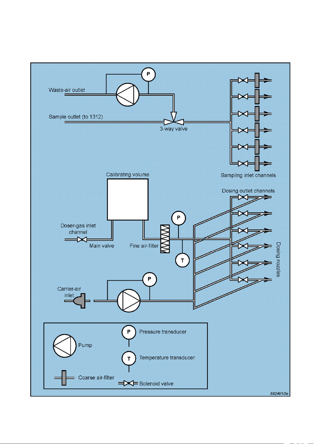
1.1 Description and Functions
Fig.1.1 The pneumatic system of the 1303
_______________________________________________________________________
BE1085-14
1303 Multipoint Sampler and Doser LumaSense Technologies A/S
Page 8 of 60
Page 9

Chapter 1
________________________________________________________________________
1.1.1 The Sampler System
The pneumatic system of the 1303 is shown schematically in Fig. 1.1.
The sampler system is constructed of 316 stainless steel and PTFE (Poly
Tetra Fluoro Ethylene) tubing to minimize adsorption of samples. The
system has 6 inlet channels, each with a solenoid valve. Each inlet
channel has a tube-mounting stub on the front-plate of the 1303; 6
tubes of up to 50m length connect each channel to the respective sampling point. The 6 inlet channels converge into one; a three-way valve
can then direct the gas sample to the Gas Monitor for analysis, or
through the pump to the waste-air outlet on the 1303’s back-plate. A
pressure transducer checks the efficiency of the sampling pump and allows checks for blocked airways.
An air-filter is attached to the end of each sampling tube to keep the
samples free of particles.
1.1.2 The Doser System
The doser system has 6 outlet channels, see Fig. 1.1, each with a solenoid valve. Each channel has a nozzle which reduces the internal diameter of the channel. The nozzles ensure that the rate of flow of tracergas to the dosing points is dependent only upon the tracer-gas supply
pressure and temperature, and is unaffected by the pressure in the
dosing tubes or at the dosing point itself. Three different nozzle sizes
are used: four medium, one large and one small. Each size gives a different volume flow rate so that the amount of tracer-gas delivered to a
particular dosing point can be matched to the requirement at that point
by using the outlet channel which has the appropriate nozzle.
Each of the 6 dosing outlet channels has a tube-mounting stub on the
front plate of the 1303. 6 tubes of up to 50m length connect each stub
to the respective dosing point.
2 separate inlet channels mounted on the back plate of the 1303 serve
the dosing channels: the tracer-gas inlet, and the carrier-air inlet.
The doser-gas inlet channel is pressurized by the tracer-gas supply cylinder, which is connected to the inlet on the 1303’s back plate by tubing. A pressure and a temperature transducer give information on the
tracer-gas supply; a fine filter ensures that the dosing channels are
particle-free. The main valve on the tracer-gas inlet channel is used to
enclose a volume of tracer-gas between itself and the dosing valves.
This volume is used when calibrating the doser system.
_______________________________________________________________________
BE1085-14
1303 Multipoint Sampler and Doser LumaSense Technologies A/S
Page 9 of 60
Page 10
Chapter 1
________________________________________________________________________
The carrier-air inlet pumps extra air to the dosing outlets to speed delivery of the tracer-gas to the dosing point. This inlet has a coarse airfilter, a pump, and a pressure transducer for checking the efficiency of
the pump. Delivering a dose of tracer-gas to a dosing point 50m distant
takes 1 minute.
The dosing system can deliver a continuous dose, that is, an uninterrupted flow of tracer-gas over a period of time; or a discontinuous
dose, in which the amount of tracer-gas delivered is reduced by interrupting the flow at regular intervals during the dosing period.
The doser system is set up for use by specifying a dosing time-out such
that the 1303 will stop any current dosing procedure after a given time
has elapsed without instruction from the controlling computer. This value is specified form the controlling computer.
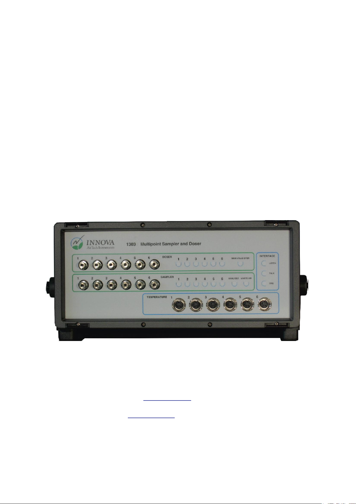
1.1.3 Front Panel
Fig.1.2 The front panel of the 1303
Doser: 6 mounting stubs for connection of tubing (AF0005, red)
to dosing points. Each stub is numbered, and has a correspondingly-numbered lamp. When the lamp is lit, it
indicates that the corresponding dosing valve is open,
see section 3.6.3. When the Main Valve Open lamp is
lit, it indicates that the main dosing valve is open, see
section 3.6.2.
Sampler: 6 mounting stubs for connection of tubing (AF0006,
green) to sampling points. Each stub is numbered, and
has a correspondingly-numbered lamp. When the lamp
_______________________________________________________________________
BE1085-14
1303 Multipoint Sampler and Doser LumaSense Technologies A/S
Page 10 of 60
Page 11
Chapter 1
________________________________________________________________________
is lit, it indicates that the corresponding sampling valve
is open, see section 3.5. The 3 Way Valve to Analyz-
er/Waste Air lamps indicate which way the internal 3
way valve is set, see section 3.5.
Temperature Sensors Input: 6 inputs suitable for use with the INNOVA Air
Temperature Transducer Type MM0034 or Operative
Temperature Transducer MM0060.
Interface: 3 lamps which indicate the function of the IEEE inter-
face. If the Listen lamp is lit, the 1303 is receiving instructions or data from the system controller. If the Talk
lamp is lit, the 1303 is outputting data. If the SRQ lamp
is lit, the 1303 has generated a Service Request, see
section 4.1.1 and 4.2.6. Full details of the IEEE Interface
are given in Chapter 4.
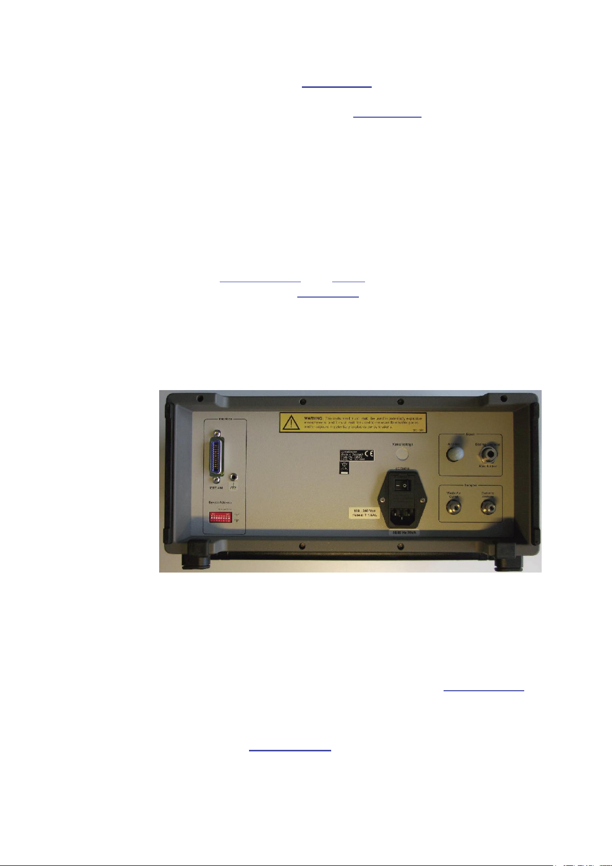
1.1.4 Rear Panel
Fig.1.3 The rear panel of the 1303
AC Mains: A 3-pin connector accepting Power Cable for connection
to a single phase AC mains supply with protective Earth.
Mains Voltage: Connect 1303 to mains supply with 100-240 Vac, 50/60
Hz
Dosing Gas Inlet: Mounting stub for connection of a tracer-gas supply to
the 1303 using tubing AF0008. See section 2.3.3.
Outlet to Analyzer: Mounting stub for connecting the sampler system of the
1303 to the inlet of an INNOVA Gas Monitor via tubing.
See section 2.3.4. Usable models are Type 1302, 1312
or 1412. In the following referred to as “Gas Monitor”.
_______________________________________________________________________
BE1085-14
1303 Multipoint Sampler and Doser LumaSense Technologies A/S
Page 11 of 60
Page 12

Chapter 1
________________________________________________________________________
Waste Air Outlet: Mounting stub for tubing to exhaust air from the 1303’s
sampler system. See section 2.3.5.
Interface IEEE-488: Digital interface designed in accordance with IEEE 488-
1978. The IEEE interface is identical in use to that described in IEC 625-1; full compatibility is only a matter
of using the correct cables and connectors. For more detail about the IEEE/IEC interface, refer to Chapter 4.
Device Address: Bank of 8 switches which decide the 1303’s interface
address. See section 2.2.2 for details of how to set the
interface address.
Air Inlet: The dosing pump inside the 1303 supply all dosing chan-
nels with carrier air for the tracer-gas, when the dosing
pump is running.
_______________________________________________________________________
BE1085-14
1303 Multipoint Sampler and Doser LumaSense Technologies A/S
Page 12 of 60
Page 13

Chapter 2
________________________________________________________________________
Chapter 2
Preparing to Use the 1303
November 2011
_______________________________________________________________________
BE1085-14
1303 Multipoint Sampler and Doser LumaSense Technologies A/S
Page 13 of 60
Page 14
Chapter 2
________________________________________________________________________
2.1 Preliminary
2.1.1 Environment and Handling
The Type 1303 Multipoint Sampler and Doser is designed for use in environments with temperatures between +5°C and +40°C (+41°F and
+104°F) and with up to 90% relative humidity (non-condensing) at
40°C. Other than ensuring correct connection of the mains supply, no
special handling precautions are necessary.
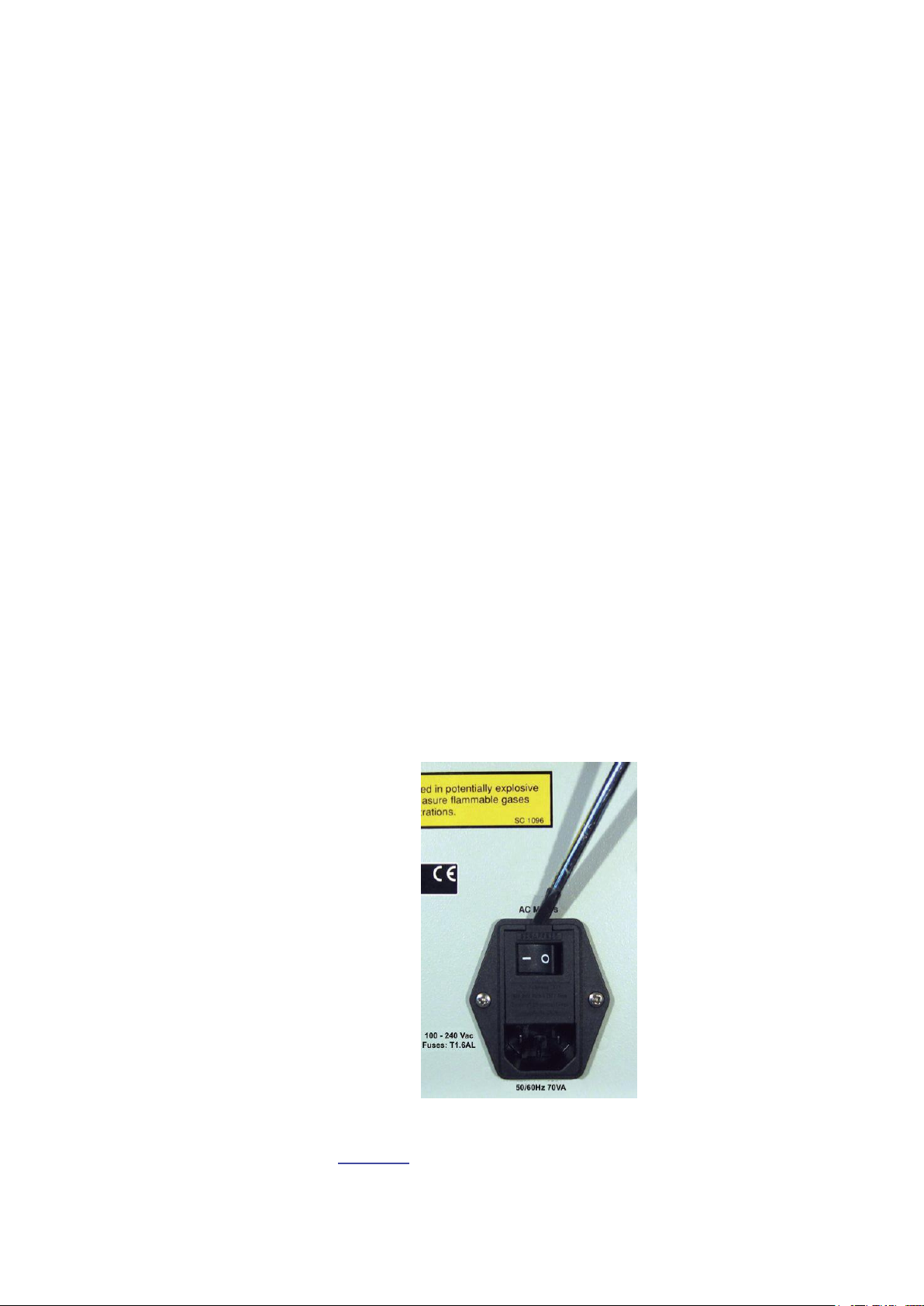
2.1.2 Connecting the Mains Supply
The 1303 is operated from a 50 to 60 Hz single phase AC mains supply.
Voltage 100-240 Vac.
Before connecting the mains supply, the following checks and adjustments should be performed to ensure safe operation of the 1303.
2.1.3 Checking the power Cord
Use the power cord supplied with the 1303 or check that the Cord used
is rated minimum 10A / 250V.
Checking Fuse Rating
Use a small flat-bladed screwdriver to prise open the flap surrounding
the AC Mains switch. See Fig. 2.1.
Fig.2.1. Accessing the 1303’s fuses
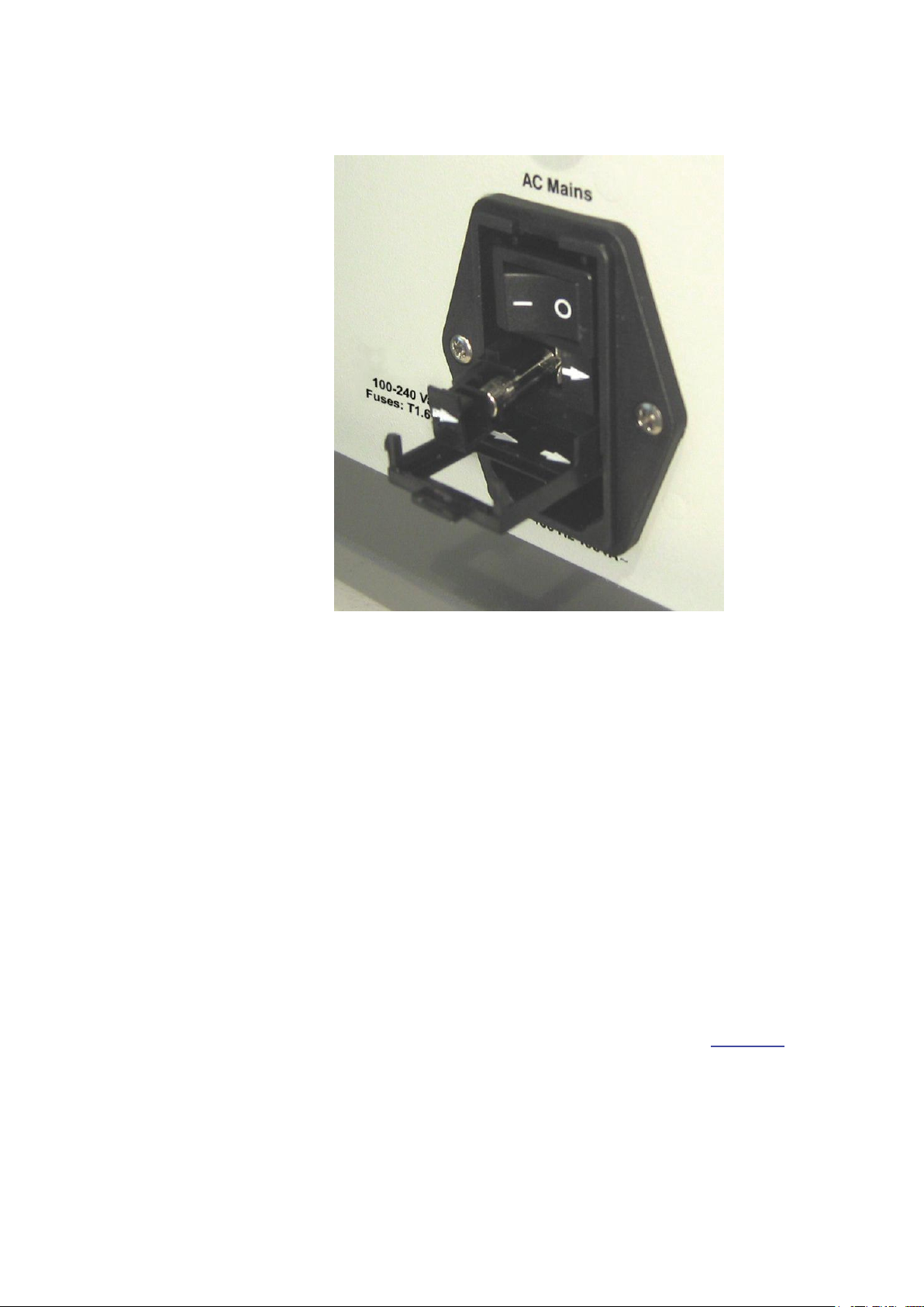
Again using the screwdriver, gently lever the fuse-holders out from
their slots. See Fig. 2.2.
_______________________________________________________________________
BE1085-14
1303 Multipoint Sampler and Doser LumaSense Technologies A/S
Page 14 of 60
Page 15
Chapter 2
________________________________________________________________________
Fig.2.2. Inserting the fuses into the 1303’s fuse holder
Use two 1,6A slow-blow fuses (LumaSense No. VF0007); Fuses are
supplied with the instrument.
When replacing the fuse-holders, ensure that the direction of the white
arrows on each holder matches the arrows marked on the covering
flap.
2.2 System Use
The 1303 combines with the Gas Monitor and a controlling computer to
provide a system which offers wide-ranging monitoring capabilities. The
1303 makes it possible to perform multi-point air-exchange analyses
and multi-point monitoring tasks in many different situations and environments, without changing the system components.
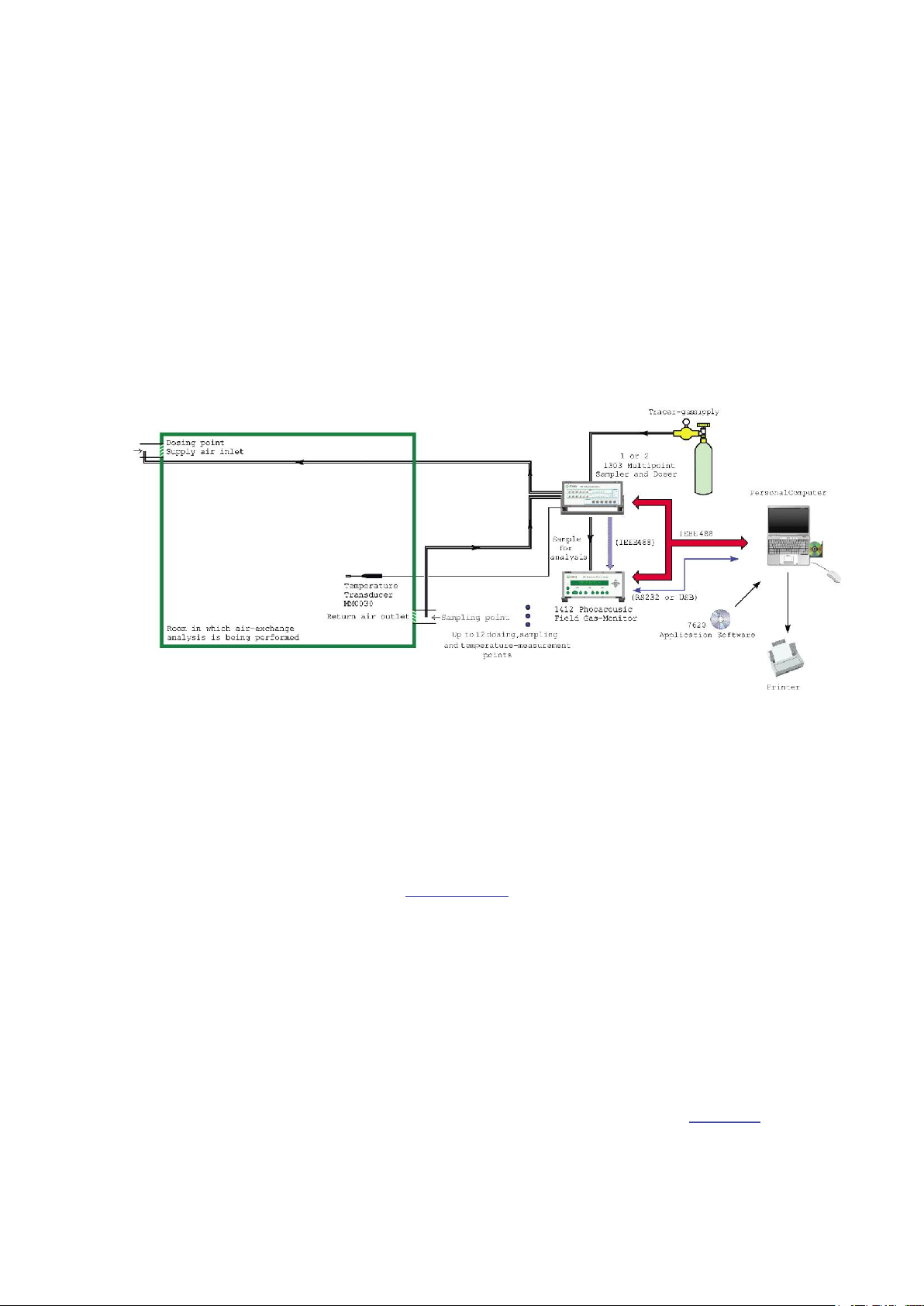
An example air-exchange analysis system is shown in Fig. 2.3. In such
a system, the doser/sampler systems of the 1303 are used as follows.
The doser system marks the supply-air of the room with a known
amount of tracer-gas. The sampler system then takes a sample of the
return-air from the room, and delivers the sample to the Gas Monitor
for analysis. While the Gas Monitor performs one analysis, the 1303
_______________________________________________________________________
BE1085-14
1303 Multipoint Sampler and Doser LumaSense Technologies A/S
Page 15 of 60
Page 16
Chapter 2
________________________________________________________________________
takes the next sample for analysis from the room. As the amount of
tracer-gas delivered to the room is known, and the remaining concentration of tracer-gas in the samples is determined by the Gas Monitor,
the ventilation-system performance can be calculated.
Fig.2.3. A typical air-change analysis system, shown with an applica-
tion example. In this case, the aim of the analysis is to determine the size of the air-change in the mechanically ventilated
room. The diagram shows only one dosing and sampling point,
for clarity. Up to 6 similar analyses can be performed simultaneously using one 1303. 7620 Application Software gives control of all the functions of the system.
2.2.1 Connecting the 1303 to the System Controller
The 1303 is connected to the computer by the IEEE interface bus, over
which the 1303 receives the commands and data which control it. Further information about the cables available from LumaSense to connect
the 1303 onto the IEEE interface bus, and about the IEEE interface of
the 1303, are given in section 4.1.
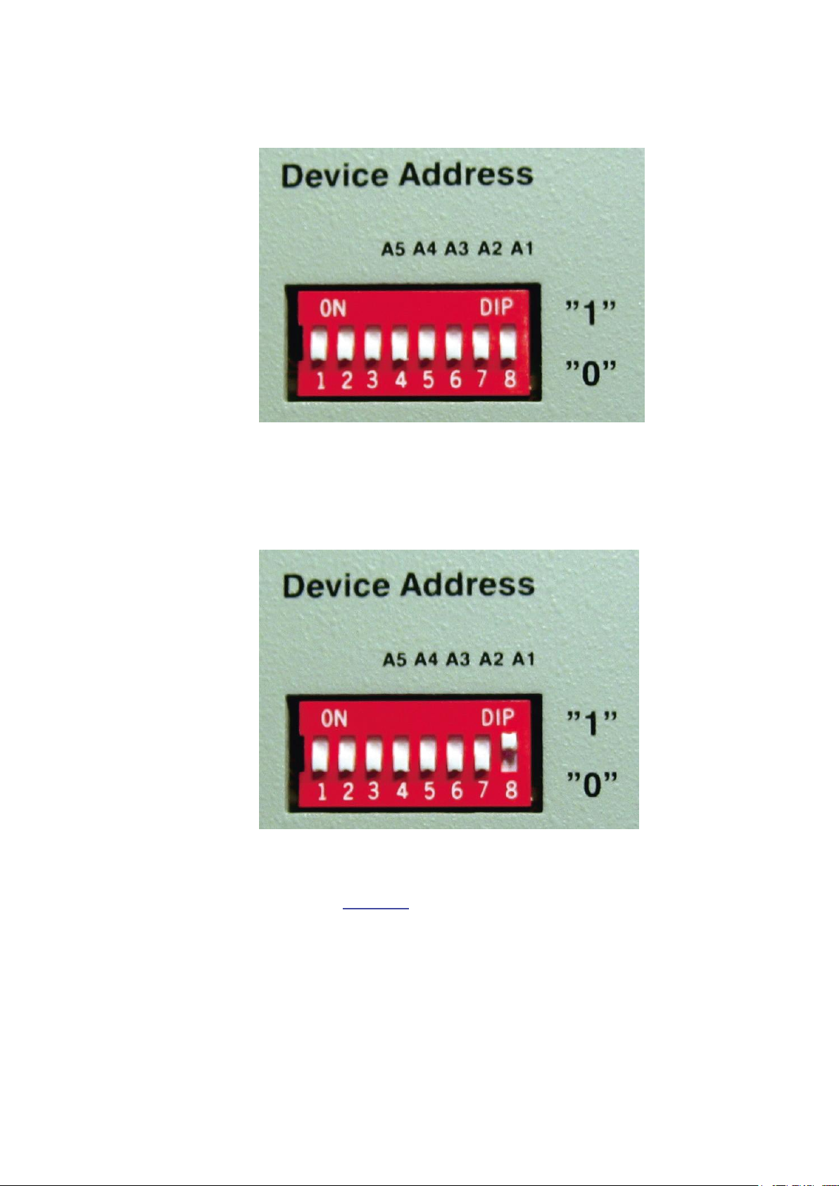
2.2.2 Setting the Interface Address of the 1303
The 1303 uses a single interface address. The address is set using the
bank of eight switches on the rear panel of the 1303. The last five
switches on the bank decide the interface address. These switches are
marked A1 (the least significant bit) to A5 (the most significant bit).
The switches represent binary values, as follows:
If the switch is down, it represents a binary “0”. See Fig. 2.4.
_______________________________________________________________________
BE1085-14
1303 Multipoint Sampler and Doser LumaSense Technologies A/S
Page 16 of 60
Page 17
Chapter 2
________________________________________________________________________
Fig. 2.4. Dipswitch settings binary “0”
If the switch is up, it represents a binary “1”. See Fig. 2.5.
Fig. 2.5 Dipswitch settings binary “1”
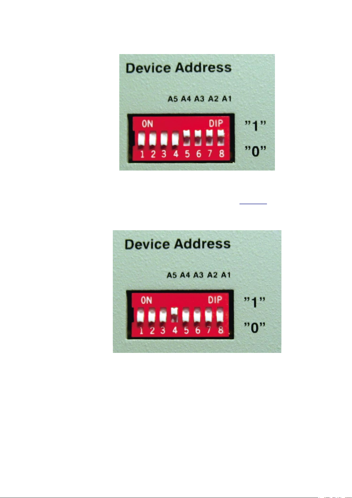
The interface address of the 1303 is set at the factory to 01111 (decimal value 15), see Fig. 2.6. If this is not suitable for your system, use
the switches to set an address appropriate to your system.
_______________________________________________________________________
BE1085-14
1303 Multipoint Sampler and Doser LumaSense Technologies A/S
Page 17 of 60
Page 18
Chapter 2
________________________________________________________________________
Fig. 2.6. Interface address 15
If the system comprise two 1303 instruments the standard interface
address of the second 1303 should be 16, see Fig. 2.7.
Fig. 2.7. Interface address 16
2.3 Connecting Tubing to the 1303
The 1303 is connected via tubing to:
the sampling points;
the dosing points (if dosing is required);
to a suitable tracer-gas supply;
to the Gas Monitor being used to analyze the gases that are sampled;
_______________________________________________________________________
BE1085-14
1303 Multipoint Sampler and Doser LumaSense Technologies A/S
Page 18 of 60
Page 19

Chapter 2
________________________________________________________________________
to a suitable exhaust for gases purged from the sampler system.
Note: the performance of the 1303’s sampling and dosing systems are
specified for sampling and dosing tubing of maximum 50m in length.
Tubing for use with the 1303 is available from LumaSense, as follows:
Sampler tubes, green nylon, LumaSense accessory number AF0006 or
Poly Tetra Fluoro Ethylene (PTFE), LumaSense accessory number
AF0614.
Doser tubes, red nylon, LumaSense accessory number AF0005 red tubing for dosing.
Tracer-gas supply tubing, nylon, LumaSense accessory number
AF0008.
Using these tubing materials minimizes the risk of gases being adsorbed onto the tube’s surface, which would result in inaccurate measurements.
2.3.1 Connecting Sampling and Dosing Tubing
Before connecting sampling and dosing tubing to the 1303, you should
know approximately where the sampling and dosing points will be in
the area to be monitored. This will allow you to estimate the length of
tubing you need to connect to the mounting-stubs of the 1303.
To connect sampling tubing, see Fig.2.8.
_______________________________________________________________________
BE1085-14
1303 Multipoint Sampler and Doser LumaSense Technologies A/S
Page 19 of 60
Page 20

Chapter 2
________________________________________________________________________
Fig.2.8. Attaching sampling and dosing tubing to the 1303’s mounting
stubs
1. Remove the knurled nut from the mounting stub of the sampler
channel you wish to use, on the front panel of the 1303.
2. Push one end of the length of the nylon AF0006 or Poly Tetra Fluoro
Ethylene PFTE AF0614 tubing through the non-threaded end of the
nut.
3. Push the end of the tubing onto the mounting stub as far as it will
go, and secure the tube by re-tightening the knurled nut onto the
threads of the mounting stub.
To connect dosing tubing:
Proceed as described above, using the nylon tubing AF0005.
2.3.2 Connecting External Filters to the Sampling Tubes
The external filters, comprising filter, LumaSense accessory number
DS2306, and fitting, LumaSense accessory number UD5041 (optional
accessories), protect the 1303’s sampling airways from airborne particles such as dust, thus helping to prevent blockage of the airways. Al-
_______________________________________________________________________
BE1085-14
1303 Multipoint Sampler and Doser LumaSense Technologies A/S
Page 20 of 60
Page 21

Chapter 2
________________________________________________________________________
so, if the Gas Monitor is measuring in the parts-per-billion range, it is
recommended that the external filters are always used to prevent degrading of the tubing’s internal surface.
The filter unit is attached to the tubing as follows, see Fig.2.9.
Fig.2.9. Attaching Fitting UD5041 and Filter DS2306 to sampling tubing
1. Push the Fitting UD5041 into the tubing.
2. Screw the short stub of the Filter DS2306 into the Fitting.
2.3.3 Connecting a Tracer Gas Supply
Tracer gases for use with the 1303 must be supplied from a pressurized
cylinder fitted with a suitable pressure-regulator. The regulator ensures
that the tracer-gas pressure is constant.
Warning! Do not attempt to connect a tracer-gas cylinder without a
pressure-regulator directly to the 1303. Doing this can damage the
1303’s internal airways.
_______________________________________________________________________
BE1085-14
1303 Multipoint Sampler and Doser LumaSense Technologies A/S
Page 21 of 60
Page 22

Chapter 2
________________________________________________________________________
The tracer-gas supply cylinder is connected to the Dosing Gas Inlet
on the rear panel of the 1303 using nylon tubing. This tubing is available from LumaSense, accessory number AF0008.
To connect the tracer-gas supply:
1. Attach one end of the tubing AF0008 to the outlet of the pressure-
regulator as recommended by the regulator manufacturer.
2. Push the other end of the tubing into the Dosing Gas Inlet stub
on the rear panel of the 1303.
After connection, slowly open the regulator’s valve and allow the pressure to rise. The tracer-gas supply pressure must be within the following range to ensure efficient dosing:
Minimum: 300 kPa (~ 3 bar) absolute
Maximum: 450 kPa (~ 4,5 bar) absolute
If you are using a pressure-regulator which displays pressure relative
to atmospheric pressure (101 kPa or 1 bar), the pressure reading
should be within the range 200 kPa to 350 kPa (2 bar to 3,5 bar).
The tracer-gas supply tubing is removed from the Dosing Gas Inlet
stub by pushing on the flange at the end of the stub, and simultaneously pulling the tubing gently.
2.3.4 Connecting the Sampler Outlet to the Gas Monitor
This connection uses the same tubing (PTFE, LumaSense No. AF0614)
as for the sampling tubes, section 2.3.1. The tubing is connected to the
Outlet to Monitor stub on the rear panel of the 1303, and to the Air
Inlet stub on the rear panel of the Gas Monitor. The tubing is con-
nected as described in section 2.3.1.
2.3.5 Waste Air Outlet
The Waste Air Outlet stub, next to the Outlet to Monitor stub on the
rear panel of the 1303, exhausts waste air from the 1303’s sampler
system as a new sample is collected. If you do not wish the waste air to
mix with the air in the room where the 1303 is positioned, connect a
length of PTFE tubing (LumaSense No. AF0614) to the Waste Air Out-
let stub and direct the tubing to a suitable exhaust-point: for example,
out of a window.
_______________________________________________________________________
BE1085-14
1303 Multipoint Sampler and Doser LumaSense Technologies A/S
Page 22 of 60
Page 23

Chapter 2
________________________________________________________________________
2.4 Connecting Temperature Transducers to the 1303
The 1303 has 6 temperature-sensor inputs mounted on its front panel,
suitable for direct use with the INNOVA Air Temperature Transducer
MM0034 or Operative Temperature Transducer MM0060.
The measurement range and accuracy of these transducers are given in
the 1303 specifications in the Product Data.
_______________________________________________________________________
BE1085-14
1303 Multipoint Sampler and Doser LumaSense Technologies A/S
Page 23 of 60
Page 24

Chapter 3
________________________________________________________________________
Chapter 3
Operation
November 2011
_______________________________________________________________________
BE1085-14
1303 Multipoint Sampler and Doser LumaSense Technologies A/S
Page 24 of 60
Page 25

Chapter 3
________________________________________________________________________
All tasks performed by the 1303 are controlled over the IEEE/IEC interface from a computer; there is no other control possibility. This chapter
deals with the control of the 1303 from the user’s point of view; for details of the IEEE/IEC interface specifications, refer to Chapter 4 of this
manual.
Sections 3.1 and 3.2 deal with switching-on and the general principles
of controlling the 1303. Sections 3.2 to 3.8 deal with the specific commands and requests, known as interface jobs, which set-up and control
the 1303. Each interface job is dealt with by giving an example which
states the effect of the job. For quick reference, an overview of all interface jobs is given in section 4.2 of this manual.
3.1 Switching-On
The 1303 can be switched on using the AC Mains switch on the backplate. After switching-on, the 1303 is set as follows:
All dosing- and sampling-valves closed;
Internal three-way valve set to Waste Air Outlet;
Both pumps stopped;
Main dosing valve closed.
3.2 General Principles of Controlling the 1303
The 1303’s functions are controlled over the IEEE/IEC interface using a
repertoire of commands and data requests, each of which is specific to
a particular function or item of data. These commands and requests are
known as interface jobs. This section describes the structure of the in-
terface jobs used to control the 1303. Further details about the
IEEE/IEC interface of the 1303 are given in Chapter 4 of this manual.
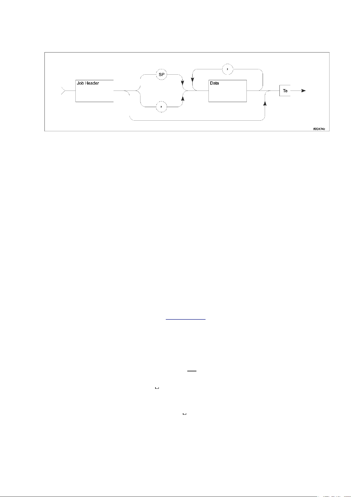
3.2.1 Syntax for Interface Jobs
Fig.3.1 shows a diagram representing a single interface job, sent from
the system controller to the 1303. Each constituent part of the interface
job is explained below.
_______________________________________________________________________
BE1085-14
1303 Multipoint Sampler and Doser LumaSense Technologies A/S
Page 25 of 60
Page 26
Chapter 3
________________________________________________________________________
Fig.3.1. General syntax diagram for interface jobs
Job Headers
The job header specifies the function you want the 1303 to perform. It
consists of one or more words. The ASCII underline character “_” is
used to separate individual words in the job header. For example:
OPEN_SAMPLING_VALVE
A hyphen “-“ or a full stop”.” can also be used to separate words in the
job header.
The words making up the job header do not need to be sent in full to
the 1303; they can be shortened to a code-form, for example:
OP_SA_VALVE
O_S_V
The minimum code for each job header is usually the first character of
each word in the job header. This is written in bold characters in the list
of interface jobs given in section 4.2 of this manual. The 1303 accepts
job headers in both upper- and lower-case characters.
The Data Field
The data field contains further information specific to the interface job
defined by the job header. The data field is separated from the job
header by a space character (“SP”), or a comma “,”. In the following
examples, the separator will always be the space character, represented by the symbol “ ”. The data field will normally contain a numerical value. For example:
OPEN_SAMPLING_VALVE
2
Some jobs may require more than one item of data. In this case, the
data is given item by item, separated by commas. For example:
_______________________________________________________________________
BE1085-14
1303 Multipoint Sampler and Doser LumaSense Technologies A/S
Page 26 of 60
Page 27

Chapter 3
________________________________________________________________________
Numerical data for interface jobs sent to the 1303 can be in NR1, NR2
or NR3 form. This is a format for describing how the numerical data is
represented, for example:
Generally, any of these data formats can be used, unless specifically
stated otherwise in the interface job overview given in section 4.2. The
number of characters in the non-exponent part of the data field must
not be greater than 8.
Job Terminators
Each interface job must have a terminator (signified by Te in Fig.3.1)
which tells the 1303 that it has received the complete interface job.
When the 1303 receives the terminator, it checks the whole job and, if
it is a valid job, carries it out.
OPEN_SAMPLING_VALVE
2,3,4
NR1 data: 250 (number without decimal-fraction or exponent)
NR2 data: 249.85 (number with decimal fraction, without exponent)
NR3 data: 2.499E-2 (number with fraction and exponent).
The terminator for communication with the 1303 is an ASCII control
character, such as “LF”. This is the default terminator character used in
communication with the 1303. The terminator character can be
changed, as follows.
To select a terminator character other than the default, use the interface job Define_Terminator, followed by the decimal value of the character you wish to use. The possible terminator characters, with the corresponding decimal values, are shown in Table 3.1.
DEF_TERMINATOR 3<LF> Selects the control character ETX
(decimal value 3) as the terminator
character.
All of the following interface job examples assume the use of “LF” as
the terminator character.
_______________________________________________________________________
BE1085-14
1303 Multipoint Sampler and Doser LumaSense Technologies A/S
Page 27 of 60
Page 28

Chapter 3
r-
r-
________________________________________________________________________
Table 3.1. The range of ASCII terminator-characters which can be used
in communication with the 1303
ASCII Cha
acter
Decimal
Code
ASCII Cha
acter
Decimal
Code
SOH 1 DC1 17
STX 2 DC2 18
ETX 3 DC3 19
EOT 4 DC4 20
ENQ 5 NAK 21
ACK 6 SYN 22
BELL 7 ETB 23
BS 8 CAN 24
HT 9 EM 25
LF 10 SUB 26
VT 11 ESC 27
FF 12 FS 28
SO 14 GS 29
SI 15 RS 30
DLE 16 US 31
3.2.2 Output Jobs – Requesting Information from the 1303
Interface output jobs request specific data from the 1303. The output
jobs allow checks of the 1303’s functions and set-up parameters. Output jobs consist of a job header followed by a question-mark; more
specific information is requested by including a data field. An example
of an output-job is:
SAMPLING_PUMP_PRESSURE?<LF>
To which the 1303 responds with the required data. The general syntax
for data output from the 1303 is shown in Fig.3.2.
Fig.3.2. General syntax diagram for data-output from the 1303
_______________________________________________________________________
BE1085-14
1303 Multipoint Sampler and Doser LumaSense Technologies A/S
Page 28 of 60
Page 29

Chapter 3
________________________________________________________________________
Generally, numerical data output from the 1303 is in NR2 form unless
specifically stated otherwise in the interface job overview given in sec-
tion 4.2. The default terminator character used is the control character
“<LF>”. The terminator character can be changed, as described in sec-
tion 3.2.1.
Re-usable Jobs
The 1303 interface jobs Calibration_Data?, Dosing_Time_Out?, Molecular_Weight? and Gas_Constant? are re-usable jobs; that is, when the
data requested by this job is read-out from the 1303, the same job can
be sent back to the system controller so that a different value for this
parameter can be read-in to the 1303. For example:
CALIBRATION_DATA?
1<LF>
Is sent to the 1303. The 1303 reads-out the calibration data for dosing
nozzle 1, with the minimum code for the job header, as follows:
C_D 1,37,45
The job can then be sent again to return the data to the 1303.
To enable the 1303 to respond to the jobs listed above with a job
header, use the Output_Header
OUTPUT_HEADER
INCLUSIVE<LF>
Inclusive as follows:
This is disabled using the following job:
OUTPUT_HEADER EXCLUSIVE<LF>
3.3 Installing Set-up Parameters
The 1303 stores in its memory 3 set-up parameters. These are the dosing time-out, the gas constant and the calibration data. Each parameter
is dealt with in turn below. The dosing time-out has a default value of
60 s. The gas constant must be installed into the 1303 before calibrating the 1303’s doser system. The calibration data must be installed before using the doser system of the 1303 – see section 3.4.
Note: after switching-off, the 1303 will revert to the default values for
each parameter. It is recommended that you read-out and note down
the current set-up parameters for future reference in the event of loss
of set-up data from the 1303. The procedure for reading-out the set-up
parameters is described in the following sections. The values for each
parameter can then be re-inserted using the jobs described in the following text.
_______________________________________________________________________
BE1085-14
1303 Multipoint Sampler and Doser LumaSense Technologies A/S
Page 29 of 60
Page 30

Chapter 3
________________________________________________________________________
3.3.1 The Dosing Time-out Parameter
This value specifies the maximum time for which the 1303 will deliver
tracer-gas without receiving further instructions about the dosing task
from the system controller. When the time period specified by the dosing time-out is exceeded, the 1303 stops delivering tracer-gas, and
sets the Dosing Nozzle Flag in the Warning Flags byte (section 3.8.5).
The range of possible values is from 10s to 3600s. If you do not specify
a value for this parameter, the 1303 uses the default value of 60s.
The dosing time-out is changed as follows.
Examples:
DOSING_TIME_OUT 30<LF> Changes the dosing time-out to
30s.
The current dosing time-out value can be checked using the following
job:
DOSING_TIME_OUT?<LF> Outputs the current dosing time-out
value from the 1303.
3.3.2 The Characteristic Gas Constant Parameter
This value is the ratio,R/M, of the universal gas constant (R=8314 J
kmol-1 K-1) and the molecular weight (kg kmol-1) of the tracer-gas being used. This is used in the calculation of the calibration data for each
dosing nozzle, and must therefore be changed before calibrating the
1303 with a different tracer-gas from the one previously used.
Note: calibration of the doser system is not possible if no value is given
for this parameter.
The range of values is from 0 to 10 000. There is no default value.
Example:
SF6 Tracer gas: SF6 molecular weight: M = 146,05 kg/kmol =
146,05 g/mol.
The Characteristic Gas Constant ParameterR/M = 8314/146,05 =
56,92
GAS_CONSTANT
56.92<LF> Sends the gas constant value 56.92
(for SF6) to the 1303.
_______________________________________________________________________
BE1085-14
1303 Multipoint Sampler and Doser LumaSense Technologies A/S
Page 30 of 60
Page 31

Chapter 3
R
M
Characteristic Gas
6
2
________________________________________________________________________
Alternatively, the gas constant can be expressed in terms of the molecular weight of the gas:
MOL_WEIGHT
146,05<LF> Sends the gram molecular weight
146,05 (for SF6) to the 1303.
The current characteristic gas constant or molecular weight value (depending on how you have previously expressed the gas constant to the
1303) can be checked using the following jobs:
GAS_CONSTANT?<LF> Outputs the current gas constant
value from the 1303.
MOL_WEIGHT?<LF> Outputs the current molecular
weight value from the 1303 in kg
kmol-1 (equivalent to g mol-1).
Table 3.2. Molecular weight of commonly used Tracer-gases
Tracer Gas M
/
Molecular Weight
SF
g/mol = kg/kmol
146.05 56.92
Constant
Freon 134a 102.03 81.49
Freon 152 66.05 125.87
CO
44.01 188.91
N2O 44.01 188.91
3.3.3 The Calibration Data Parameter
This specifies the effective outflow area (in m2x 10-9) of a specific dosing nozzle, thus allowing the 1303 to automatically calculate the
amount of tracer-gas delivered during a dosing procedure. The 1303 is
able to calculate these values automatically for each dosing nozzle
when calibrating itself – see section 3.4 for further information. A dosing nozzle cannot be used until it is calibrated with the tracer-gas to be
used.
The range of values is from 0,1 to 100,0; there is no default value for
this parameter.
If the calibration data for each specific nozzle and for the tracer-gas
currently being used is known, it can be sent directly to the 1303 using
the following job, without calibrating the 1303. Note that the 1303’s
doser nozzles must still be calibrated with each change of tracer-gas,
so that the 1303 is able to calculate the amount delivered.
_______________________________________________________________________
BE1085-14
1303 Multipoint Sampler and Doser LumaSense Technologies A/S
Page 31 of 60
Page 32

Chapter 3
________________________________________________________________________
Example:
CALIB_DATA
1,1.25<LF> Sets the calibration data of number
1 dosing nozzle to 1.25.
To avoid having to calibrate each dosing nozzle after each time the
1303 has been switched off, it is recommended that the calibration data
for each nozzle is read-out and noted for future reference. The calibration data for a specific nozzle can be checked using the following job.
CALIBRATION_DATA?
1<LF> Outputs the calibration data for dos-
ing nozzle number 1.
3.4 Calibrating the Doser System
Each of the nozzles in the 1303’s doser system must be calibrated so
that the amount of tracer-gas delivered during a given dosing procedure can be accurately determined. The 1303’s doser system must be
calibrated before performing any dosing tasks, and also every time you
use a different tracer-gas from the one used previously.
A volume of tracer-gas is enclosed between the main valve and the
dosing valves; this volume is then released through the nozzle to be
calibrated. As the internal volume of the airways are known, the effective outflow area for each nozzle is calculated from the rate of pressure-decrease measured in the dosing airway. The amount of tracergas delivered can then be calculated from the effective outflow area,
the tracer-gas supply pressure and temperature, and the dosing timeperiod.
Once started, using the appropriate interface job, the 1303’s calibration
procedure is fully automated.
Note: ensure that a tracer-gas supply is connected to the 1303 as described in section 2.3.3 before starting calibration, otherwise calibration
cannot be performed.
If you do not want the tracer-gas used for calibration to mix with the
air in the room in which you are performing the calibration, attach tubing to the dosing nozzle (section 2.3.1) to direct the tracer-gas out of
the room.
Important! To ensure accurate calibration of the 1303, observe the
following points before performing the calibration procedure.
1. The 1303 must be placed in the area in which it will be used, with
power on, at least 10 minutes before calibrating. This allows the
_______________________________________________________________________
BE1085-14
1303 Multipoint Sampler and Doser LumaSense Technologies A/S
Page 32 of 60
Page 33

Chapter 3
________________________________________________________________________
1303’s temperature to stabilize in relation to the temperature of
the area in which it will be used.
The main dosing valve and each dosing valve must be opened to
allow tracer-gas to flow into the 1303’s dosing manifold, for 5
minutes before calibrating. This ensures that the temperature of
the dosing system will stabilise relative to the temperature of the
tracer-gas. The procedures for opening the main dosing valve and
the dosing valves, to allow flow of tracer-gas through the dosing
system, are described in section 3.6.2 and 3.6.3 respectively. To
ensure that the tracer-gas does not flow into the room in which you
will be performing measurements, direct the outlets of the doser
tubing to a suitable exhaust – for example, out of a window. After
flushing is complete, wait for 15 minutes before proceeding with
the calibration.
2. If you are to use a different tracer-gas from the one used previously, you must first flush the doser system with the new tracergas, before calibrating with the new tracer-gas. Flushing is done as
described above. Once flushing is completed, remember to change
the characteristic gas-constant value stored in the 1303 to that for
the new tracer-gas before performing the calibration. This procedure is described in section 3.3.2.
Examples:
CALIBRATE_NOZZLE
1<LF> Starts the 1303’s self-calibrating
procedure for dosing nozzle number
1. Each nozzle calibration takes approximately 5 minutes. If no dosing
nozzle number is given, the 1303
will calibrate all the dosing nozzles.
Each of the dosing nozzles that you wish to use must be calibrated in
this way. Once the procedure is complete, the new calibration data for
each nozzle can be read-out using the following job:
CALIBRATION_DATA?
1<LF> Outputs the calibration data for dos-
ing nozzle number 1. If no nozzle
number is given, the calibration data for all 6 nozzles is output.
Note: the 1303 does not maintain the calibration data in its memory
after switching-off. It is recommended that you read-out and note
down the current calibration data for each nozzle, for future reference
in the event of loss of calibration data from the 1303. The calibration
data can then be re-installed using the Calibration_Data job, section
3.3.3.
_______________________________________________________________________
BE1085-14
1303 Multipoint Sampler and Doser LumaSense Technologies A/S
Page 33 of 60
Page 34

Chapter 3
________________________________________________________________________
3.5 Using the Sampler System
Using the 1303’s sampler system (see Fig. 1.1), to deliver a sample to
the Gas Monitor is a 3-stage process:
1. The required sample valve is opened; all other sample valves are
closed automatically. The sampling pump starts.
2. The sample valve is connected to the sampling pump via the
1303’s internal 3-way valve, allowing the waste air to be exhausted from the sample channel (via the Waste Air Outlet,
section 2.3.5) and drawing the new sample.
3. When the new sample has been drawn to the 1303, the internal
3-way valve is set to direct the sample to the Gas Monitor. The
sampling pump stops, and the Gas Monitor’s pump draws the
sample for analysis.
While the Gas Monitor is analyzing this sample, the next sample can
then be drawn ready for the next analysis.
Three interface jobs control the sampling process.
Examples:
OPEN_SAMP_VALVE
1<LF
Opens sample valve 1, closes all
other sample valves and starts
>
the sampling pump. If no sample valve is specified, all sample
valves are closed.
CONNECT_SAMP_VALVE
TO_SAMPLING_PUMP<LF>
Connects the sample valve to
the sampling pump, and exhausts the waste air from the
sample channel.
CONNECT_SAMP_VALVE
TO_MONITOR<LF>
Stops the 1303’s sampling
pump, and directs the new sam-
ple to the Gas Monitor for analy-
sis.
The time taken to draw a sample depends upon the length of the sampling tube. The gas-transport speed in a tube of internal diameter 3mm
is 2m s-1, assuming that the sampling pump is working within its design
_______________________________________________________________________
BE1085-14
1303 Multipoint Sampler and Doser LumaSense Technologies A/S
Page 34 of 60
Page 35

Chapter 3
________________________________________________________________________
limits. The pressure across the sampling pump can be checked to ensure efficient gas-transport; see section 3.8.1 for details.
The sampling pump can be controlled using the following jobs:
SAMPLING_PUMP
SAMPLING_PUMP OFF<LF> Stops the sampling pump.
ON<LF> Starts the sampling pump.
3.6 Using the Doser System
The 1303 can perform two types of dosing tasks: continuous, which
gives an uninterrupted flow of tracer-gas over a period of time; or dis-
continuous, where the flow of tracer-gas is interrupted at regular intervals during a given dosing time. These tasks are dealt with in turn below.
Before starting any dosing tasks, the 1303’s doser system (see Fig.1.1)
must be calibrated with the tracer-gas to be used – see section 3.4 for
details of how to do this. The 1303 cannot open a dosing valve for
which calibration data does not exist.
To ensure efficient dosing, the tracer-gas pressure must be in the range
300 kPa to 450 kPa absolute.
3.6.1 The Dosing System
Flushing Recommendation
After the Type 1303 has been used for dosing, it should be flushed
through with nitrogen gas. This can be done using the “Flush Function”
featured in Type 7620 Application Software.
Releasing the Pressure
The pressure inside the 1303 must be released before storage. This can
be done by closing the valve to the dose-gas bottle, or by removing the
tube supplying the dose gas to the 1303 while it is dosing.
Failure to release this pressure can result in the piston inside the dosing
outlet valve(s) becoming stuck to the rubber seal. This can result in the
valve having difficulty opening the next time the instrument is used.
3.6.2 Opening the Main Dosing Valve
The main dosing valve (see Fig.1.1), which isolates the tracer-gas supply from the internal airways of the 1303, must first be opened.
Example:
_______________________________________________________________________
BE1085-14
1303 Multipoint Sampler and Doser LumaSense Technologies A/S
Page 35 of 60
Page 36

Chapter 3
________________________________________________________________________
MAIN_DOS_VALVE
OP<LF> Opens the main dosing valve to al-
The main dosing valve will close automatically to protect the dosersystem airways if the tracer-gas pressure in the dosing manifold is
above 550 kPa absolute.
3.6.3 Starting Continuous Dosing
Using the interface job described below starts an uninterrupted flow of
tracer-gas through the specified dosing valves. Any number of the dosing valves can be opened simultaneously. The valve specified in the interface job will be opened; those not specified are closed. The 1303’s
doser system is also equipped with a pump which pumps carrier-air
through the dosing valves to accelerate delivery of the tracer-gas to the
dosing points. The dosing pump is controlled separately from the dosing valves.
Note: the carrier-air inlet on the rear panel of the 1303 must not be
blocked.
low the flow of tracer-gas to the
dosing valves.
Example:
OPEN_DOSING_VALVE
1,2<LF>
Opens only dosing valves 1 and
2. If no dosing valves are speci-
fied, all dosing valves are closed.
The dosing pump must then be started. The pump is controlled using
the following commands.
DOSING_PUMP
ON<LF> Starts the carrier-air pump.
DOSING_PUMP OFF<LF> Stops the carrier-air pump.
If no further instructions are sent to the 1303, the dosing procedure
will be stopped automatically when the time-period specified by the
Dosing Time-out parameter, section 3.3.1, has elapsed. To continue the
task in progress, the same job should be sent again to the 1303 before
the dosing time-out period has elapsed.
The carrier-air pump can be used to effect air-change in the casing of
the 1303, to prevent a build-up of the concentration of tracer-gas in
the casing of the 1303. This is done using the interface job DOS-
ING_PUMP
AUTO. When sent to the 1303, this job causes the doser
pump to start automatically whenever the pressure in the 1303’s doser
_______________________________________________________________________
BE1085-14
1303 Multipoint Sampler and Doser LumaSense Technologies A/S
Page 36 of 60
Page 37
Chapter 3
________________________________________________________________________
system is higher than 125kPa. The pump operates for one minute, then
stops for one minute, then operates for one minute, and so on.
Example:
DOSING_PUMP
AUTO<LF> Runs the carrier-air pump for one
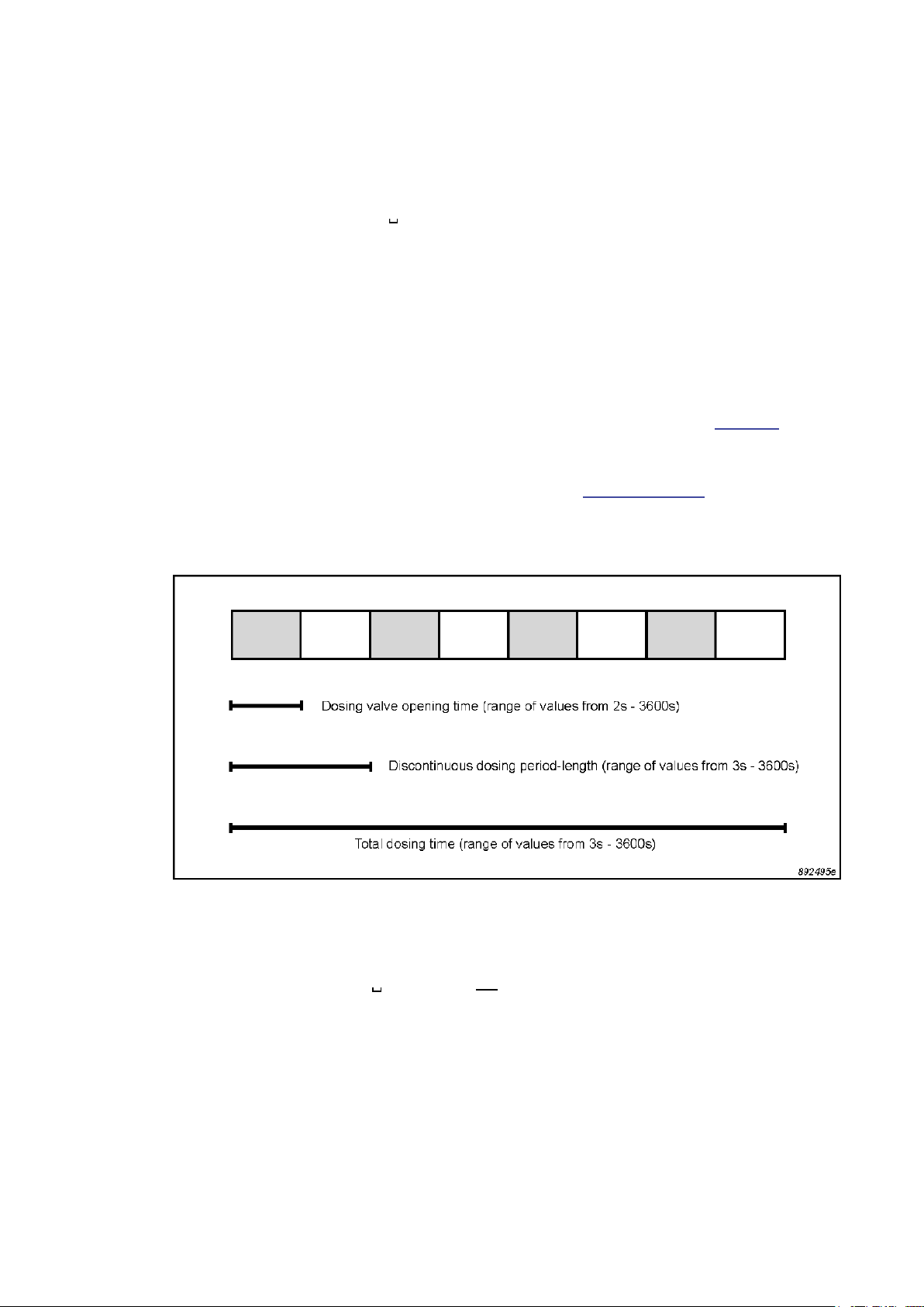
3.6.4 Starting Discontinuous Dosing
This interface job starts a flow of tracer-gas which is interrupted at
regular intervals during a given total dosing time – see Fig.3.3. The discontinuous dosing job comprises four data elements: the dosing valve
number; the total dosing time; the discontinuous dosing period-length;
and the dosing valve opening period, see section 4.2.3.
Fig.3.3. Representation of the 1303’s discontinuous dosing function
minute, at one minute intervals,
whenever the pressure in the
1303’s doser system rises above
125kPa.
Example:
DIS_DOSING
1,20,5,3<LF> Starts a discontinuous dosing pro-
cedure through dosing valve number 1 for a total time of 20s. The
discontinuous dosing period-length
is 5s, during which the dosing valve
is open for 3s.
_______________________________________________________________________
BE1085-14
1303 Multipoint Sampler and Doser LumaSense Technologies A/S
Page 37 of 60
Page 38

Chapter 3
________________________________________________________________________
DIS_DOSING
3,60,6,2<LF> Starts a discontinuous dosing pro-
cedure through dosing valve number 3 for a total time of 60s. The
discontinuous dosing period-length
is 6s, during which the dosing valve
is open for 2s.
DIS_DOSING
1,20<LF> Starts a dosing procedure in which
dosing valve number one is open
continuously for 20s.
DIS_DOSING 1<LF> Stops any current discontinuous
dosing procedure through dosing
valve number one.
3.6.5 Calculating the Dosage Delivered
When each dosing-nozzle is calibrated with the tracer-gas being used
(section 3.4) the 1303 is able to calculate the delivered dosage automatically. The delivered dosage is read-out from the 1303 as follows:
Example:
DOSAGE_GIVEN? 1<LF> Outputs from the 1303 the dosage
3.7 Temperature Measurement
The temperature measured by the Air Temperature Transducers
MM0034 and MM0060 is read out from the 1303 as follows:
Example:
SENSOR_TEMP?
1<LF> Reads-out the temperature data in
(in mg) delivered through dosing
valve number 1 since the last time
the dosage was read-out. If no dosing valve is specified, the 1303
reads-out the dosages delivered
through each of the 6 dosing
valves.
°C from the temperature transducer
connected to input number 1. If no
transducer is connected to the particular input, -100°C is output by
the 1303.
_______________________________________________________________________
BE1085-14
1303 Multipoint Sampler and Doser LumaSense Technologies A/S
Page 38 of 60
Page 39

Chapter 3
________________________________________________________________________
3.8 Checking the 1303
These interface jobs are for checking the various functions of the hardware and software components of the 1303, and help to identify faults
in the 1303.
3.8.1 Sampling_Pump_Pressure? Interface Job
This job reads-out the pressure-difference across the sampling pump.
The pressure across the pump can be measured with the sampling
valves either open or closed. The internal 3-way valve must be set to
Waste Air Outlet.
Example:
SAMP_PUMP_PRESS?<LF> Measures and outputs the pressure-
difference across the sampling
pump, in kPa. With all sampling
valves closed, the pump should
generate a pressure-difference
greater than 40kPa. With the sampling valves open, the pressuredifference should be less than 25
kPa.
3.8.2 Dosing_Pump_Pressure? Interface Job
This job reads-out the pressure-difference across the dosing pump,
which supplies the carrier-air for dosing.
Example:
DOS_PUMP_PRESS?<LF> Measures and outputs the pressure-
difference across the dosing pump,
in kPa. This value should be at least
10kPa.
3.8.3 Status? Interface Job
This job reads-out the 1303’s current mechanical condition. The 1303’s
current condition is shown as a “flag”, i.e. a word-value comprising 16
bits, each of which represents a specific mechanical component. If a bit
is set, the 1303 is currently using the corresponding component. The
flag is output from the 1303 as the total of the decimal equivalents of
the binary values of the bits which are set. See Table 3.3 for the com-
_______________________________________________________________________
BE1085-14
1303 Multipoint Sampler and Doser LumaSense Technologies A/S
Page 39 of 60
Page 40

Chapter 3
Bit
1
2
4
8
16
32
64
Main dosing valve
128
256
512
1024
2048
4096
8192
16384
68
________________________________________________________________________
ponents represented by each bit in the Status flag, and their corresponding decimal values.
Table 3.3. The 1303’s Status Flag. Each bit represents a particular
1303 component; when set, the 1303 is currently using
that component.
Dec.
no.
value
1
2
3
4
5
6
7
8
9
10
11
12
13
14
15
16 327
Status Flag
Bit name
Dosing valve 1 Dosing valve 1 open
Dosing valve 2 Dosing valve 2 open
Dosing valve 3 Dosing valve 3 open
Dosing valve 4 Dosing valve 4 open
Dosing valve 5 Dosing valve 5 open
Dosing valve 6 Dosing valve 6 open
Dosing pump Dosing pump on
Sampling valve 1 Sampling valve 1 open
Sampling valve 2 Sampling valve 2 open
Sampling valve 3 Sampling valve 3 open
Sampling valve 4 Sampling valve 4 open
Sampling valve 5 Sampling valve 5 open
Sampling valve 6 Sampling valve 6 open
3-way valve 3-way valve set to ana-
Sampling pump Sampling pump on
Current function when
set
Main dosing valve open
lyzer
Example:
STATUS?<LF> Outputs the Status flag of the 1303
as described above. Refer to Table
3.3 for the decimal values of each
bit. Refer also to the examples given below.
If the 1303 outputs 33024, using Table 3.3 shows that 33024 = 256 +
32768. Therefore, bits 9 and 16 are set. The mechanical condition of
the 1303 is: sampling valve number 1 open, and the sampling pump
running.
If the 1303 outputs 199, using Table 3.3 shows that 199 = 1 + 2 + 4 +
64 + 128. Therefore, bits 1, 2, 3, 7 and 8 are set. The mechanical condition of the 1303 is: dosing valves 1, 2 and 3 open; main dosing valve
open; dosing pump running.
_______________________________________________________________________
BE1085-14
1303 Multipoint Sampler and Doser LumaSense Technologies A/S
Page 40 of 60
Page 41

Chapter 3
________________________________________________________________________
3.8.4 Check_System Interface Job
This job starts a self-test sequence. This test sequence checks the functions of the 1303’s sampler system with a two-part test, as follows.
1. Check of the sampling pump efficiency and air tightness: all
6 sampling valves are closed, the internal 3-way valve is set to
Waste Air Outlet and the sampling pump started. If the pressure
difference across the pump is less than 40kPa, either the sampling
pump is not operating efficiently, or there is an air-leak around the
pump. This sets the Sampling System Flag in the Warning Flags
byte – see section 3.9.4.
2. Check of blocked sampling channels: all 6 sampling valves are
closed, the internal 3-way valve is set to Waste Air Outlet and the
sampling pump started. One by one the sampling valves are
opened. If the resulting pressure difference across the pump (with
open sampling valves) is greater than 25 kPa, then the sampler
system airways are blocked. This sets the Sampling Channel Flag in
the Error Flags byte – see section 3.9.5.
If the above conditions cannot be met, the setting of the corresponding
Error flag causes a Service Request to be generated, if enabled – see
section 4.1.1 and 4.2.6.
Example:
CHECK_SYSTEM<LF> Starts the 1303’s self-test sequence
3.8.5 Reset_System Interface Job
This interface job restarts the 1303. This job does not reset the 1303’s
set-up parameters or calibration data. The 1303 restarts as described
in section 3.1. Resetting the 1303 cancels any task which the 1303 was
performing prior to the reset.
Example:
RESET_SYSTEM<LF> Resets the 1303.
as described above.
3.9 Error Conditions and Service Requests
If an error arises in the 1303’s hardware, processor system or software,
the 1303 can signal the system controller by generating a Service Re-
_______________________________________________________________________
BE1085-14
1303 Multipoint Sampler and Doser LumaSense Technologies A/S
Page 41 of 60
Page 42

Chapter 3
Bit no.
Dec. Value
Set when the 1303 has completed an interface
-
________________________________________________________________________
quest. The exact nature of the error condition can then be investigated
by using the Warning? or Error? interface jobs.
3.9.1 The Status Byte
The status byte is an eight-bit byte, read out by the system controller
as part of the serial poll sequence. The status byte gives the first indication of the cause of the service request. The status byte for the 1303
is shown in Table 3.4.
Table 3.4 The 1303’s Status Byte, showing the error conditions which
result in the individual bits being set.
Status Byte Error Condition
1 1 Not used
2 2 Set when the 1303 has completed a reset
3 4
job
4 8 Not used
5 16 Set when the 1303 has not completed the pre
vious interface job when a new job is read-in
6 32 The 1303 is in an abnormal condition. The in-
terface jobs Warning? or Error? give more in-
formation about the abnormal condition – see
section 3.9.4 and 3.9.5
7 64 Indicates the 1303 has set the interface SRQ
line. This bit cannot be disabled
8 128 Set when the time period given in the dosing
time-out set-up parameter (section 3.3.1) has
elapsed
For an error to generate a Service Request, the corresponding bit in the
status byte must be enabled to request service. The procedure for this
is described in the following section.
When a service request is enabled, all bits in the status byte except bit
6 are reset by a serial poll read-out or resetting the status byte. Bit 6 is
only reset when the abnormal condition of the 1303 (identified by the
Warning? or Error? interface jobs, sections 3.9.4 to 3.9.5) is corrected.
When a service request is generated, bit 7 of the status byte is always
set; it cannot be disabled.
3.9.2 Enabling Service Requests
The Specified bits in the status byte are enabled using the interface job
Service_Request_Enable. The required bits are specified by using the
_______________________________________________________________________
BE1085-14
1303 Multipoint Sampler and Doser LumaSense Technologies A/S
Page 42 of 60
Page 43

Chapter 3
________________________________________________________________________
decimal equivalent of their binary value, as shown in Table 3.4. See also the job examples below for further clarification.
Note that the relevant bits are always set whenever the corresponding
condition occurs; this job only enables or disables the generation of a
service request by that condition.
Examples:
S_R_E 32<LF> Service request is generated by the
setting of bit 6 (bit pattern
00100000 = 25 = 32 decimal) in
Table 4.3.
S_R_E
S_R_E
160<LF> Service request is generated by the
0<LF> All bits are disabled (except bit 7).
The bits which are enabled in the status byte can be read-out using the
Service_Request_Enable? interface job:
S_R_E?<LF> Outputs the sum of the decimal val-
3.9.3 Resetting the Status Byte
The job Reset_Status_Byte is used for this task.
setting of bit 6 and bit 8 (bit pattern
10100000 = 25 + 27 = 32 + 128 =
160 decimal).
ues of the bits which are enabled.
For example, if the decimal readout is 48, the enabled bits are bit 5
and bit 6 (bit pattern 00110000 =
25 + 26 = 16 + 32 = 48 decimal).
Example:
R_S_B<LF> Resets the bits in the status byte to
zero.
3.9.4 The Warning? Interface Job
This job reads-out an 8-bit byte (the Warning Flags) which gives information about error conditions which affect the efficient operation of the
1303. The 1303 is still able to operate, but the error should be rectified
as soon as possible. The Warning Flag byte is shown in Table 3.5.
_______________________________________________________________________
BE1085-14
1303 Multipoint Sampler and Doser LumaSense Technologies A/S
Page 43 of 60
Page 44

Chapter 3
Bit no.
Dec. Value
________________________________________________________________________
Table 3.5. The 1303’s Warning Flags byte
WARNING FLAGS
Flag Description
1 1 Reset Done Flag
2 2 Temperature Flag
3 4 Power Fail Flag
4 8 Sampling System Flag
5 16 Dosing Filter Flag
6 32 Dosing Nozzle Flag
7 64 Dosing Pump Flag
8 128 Calibration Flag
Warning Flags are set when either the 1303’s self-check procedures or
the Check_System interface job identify an error condition. This in turn
sets bit 6 of the Status Byte (generating a service request, if enabled)
to indicate that an error condition exists. The Warning? job can then
give more information about the cause of the error condition.
Example:
Warning?<LF> Outputs the Warning Flags from the
The conditions which causes the Warning Flags to be set, and the appropriate action to take, are dealt with in turn below.
Reset Done Flag
Indicates that the 1303 has completed a reset, following either the Reset_System interface job (section 3.8.5) or switching-on the 1303. This
flag is reset when the Warning Flags are read-out from the 1303.
Temperature Flag
Is set when the internal temperature of the 1303 is outside the range
+2°C to +60°C. The 1303 must not be used until the internal temperature is within the normal operating limits of +5°C to +40°C. This
flag is reset when the internal temperature is again within the normal
operating limits, or by resetting the 1303, or switching the 1303 off/on.
1303. A “1” indicates that the flag is
set; a “0” indicates the flag is not
set.
_______________________________________________________________________
BE1085-14
Power Fail Flag
Is set if the power from the 1303’s transformer to the 1303 is outside
the range 13,25V to 15,75V. This flag is reset when the voltage is back
within the above range, or by resetting the 1303, or switching the 1303
off/on. If the error is persistent, have the 1303 serviced.
1303 Multipoint Sampler and Doser LumaSense Technologies A/S
Page 44 of 60
Page 45

Chapter 3
________________________________________________________________________
Sampling System Flag
Is set if, during the self-test specified in test 3 of the Check_System
job (section 3.8.4) the pressure across the pump is less than 40kPa.
This indicates that either the sampling pump is not working correctly,
or that the sampler system is not sufficiently air-tight. This flag is reset
by the next Check_System job (if the results of the check are satisfactory), or by resetting the 1303, or switching the 1303 off/on. If the error is persistent, have the 1303 serviced.
Dosing Filter Flag
Is set with the Calibrate_Nozzle job (section 3.4) if the rate of pressure-increase in the doser system during a calibration is too slow. This
indicates either a blocked dosing-filter or the tracer-gas supply bottle is
empty. If the tracer-gas supply bottle is empty, replace it with a full
bottle. If the tracer-gas bottle is not empty, the dosing-filter is blocked,
and the 1303 must be serviced. This warning can also be caused by the
regulator on the dose-gas bottle reacting too slowly. The flag is reset
by the next calibration, or by resetting the 1303, or switching the 1303
off/on.
Dosing Nozzle Flag
Is set with the Calibrate_Nozzle job (section 3.4) if the newly-
calculated nozzle area is 2-times larger or smaller than the existing
largest and smallest nozzle. This indicates that the calibration procedure was not performed correctly. The calibration procedure must then
be repeated. This flag is also set when the time specified by the dosing
time-out set-up parameter has been exceeded (section 3.3.1). The flag
is reset by the next calibration, or by resetting the 1303, or switching
the 1303 off/on.
Dosing Pump Flag
Is set if the pressure generated by the carrier-air pump is less than
10kPa above ambient pressure. This indicates that the carrier-air pump
is not working correctly. The flag is reset when the pressure generated
by the pump is over 15kPa above ambient pressure, or by resetting the
1303, or switching the 1303 off/on. If the error persists, have the 1303
serviced.
Calibration Flag
Is set when a dosing procedure is attempted through a dosing channel
which has not been calibrated, or if no characteristic gas-constant (or
molecular weight) has been read-out to the 1303 before starting the
dosing procedure. A non-calibrated dosing channel cannot be used for
dosing. Dosing procedures cannot be performed without reading-in a
characteristic gas-constant. The flag is reset by calibrating the dosing
channel (section 3.4) or reading in the characteristic gas-constant for
the tracer-gas being used (section 3.3.2). Resetting the 1303 or
switching the 1303 off/on also resets the flag.
_______________________________________________________________________
BE1085-14
1303 Multipoint Sampler and Doser LumaSense Technologies A/S
Page 45 of 60
Page 46

Chapter 3
Dec. Value
________________________________________________________________________
3.9.5 The Error? Interface Job
This job reads-out an 8-bit byte (the Error Flags) which gives information about errors which cause the 1303 to stop working. If any of these
errors exist, the 1303 is unable to function until the error is rectified.
The Error Flag byte is shown in Table 3.6.
Table 3.6 The 1303’s Error Flags byte
ERROR FLAGS
Bit no.
1 1 ADC Flag
2 2 RAM Flag
3 4 PROM Flag
4 8 Sampling Channel Flag
5 16 Dosing-pressure Flag
6 32 Job Specification Error
7 64 Software Error Flag
8 128 Set-up Error Flag
Flag Description
Error Flags are set when either the 1303’s self-check procedures or the
Check_System interface job identify an error condition. This in turn
sets bit 6 of the Status Byte (generating a service request, if enabled)
to indicate that an error condition exists. The Error? job can then give
more information about the cause of the error condition.
Example:
The conditions which cause the Error Flags to be set are dealt with in
turn below.
ADC Flag
Is set when the ADC (analogue-digital converter) develops an error.
This results in a software-error, which automatically resets the 1303.
The flag is reset by reading-out the Error Flags, or by switching the
1303 off/on. If the error persists, have the 1303 serviced.
Error?<LF> Outputs the Error Flags from the
1303. A “1” indicates that the flag is
set; a “0” indicates the flag is not
set.
_______________________________________________________________________
BE1085-14
1303 Multipoint Sampler and Doser LumaSense Technologies A/S
Page 46 of 60
Page 47

Chapter 3
________________________________________________________________________
RAM Flag
Indicates that the RAM (random access memory) of the 1303, which
stores the 1303’s set-up data, has been corrupted. The flag is reset by
switching the 1303 off/on. If the error persists, have the 1303 serviced.
PROM Flag
Indicates that the CRC (cyclic redundancy check) for the PROM (programmable read-only memory) has identified incorrect data. The flag is
reset by switching the 1303 off/on. If the error persists, have the 1303
serviced.
Sampling Channel Flag
Is set during the self-test specified in the Check_System job (section
3.8.4), or when drawing a sample with the 3-way valve set to Waste
Air Outlet, if the pressure across the sampling pump is above 25kPa.
This indicates that the sampler-system airways may be blocked. The
flag is reset by reading-out the Error Flags, or by switching the 1303
off/on. If the error persists, have the 1303 serviced.
Dosing-pressure Flag
Is set when calibrating the dosing nozzles, or when performing a dosing
task if the tracer-gas pressure in the dosing manifold is outside the
range 295kPa to 455 kPa absolute. Calibration cannot continue if the
tracer-gas pressure is outside of this range. The flag is also set if the
tracer-gas pressure rises above 550kPa when the Main Dosing Valve is
open; the Main Dosing Valve closes automatically at this pressure. The
flag is reset when the tracer-gas pressure is within the specified limits;
or by resetting the 1303, or switching the 1303 off/on.
Job Specification Error
Is set if an interface job sent to the 1303 is not recognised. This can be
due to an incorrect job header, incorrect syntax, or incorrect or missing
data. This flag is also set when calibrating the dosing nozzles, if no
characteristic gas-constant (or molecular weight) has been read-in to
the 1303 (section 3.3.2). A job cannot be carried out by the 1303 if this
flag is set. The job’s syntax should be checked carefully and the job
sent again. The flag is reset by reading-out the Error Flags, or by
switching the 1303 off/on.
Software Error Flag
Is set when the 1303’s software develops an error when running. When
this flag is set, the 1303 is reset automatically. The flag is reset by
reading-out the Error Flags, or by switching the 1303 off/on. If the error persists, have the 1303 serviced.
Set-up Error Flag
This flag is set when the 1303’s set-up parameters (described in section
3.3 and 4.2.1) are deleted. This happens because either the 1303’s set-
_______________________________________________________________________
BE1085-14
1303 Multipoint Sampler and Doser LumaSense Technologies A/S
Page 47 of 60
Page 48

Chapter 3
________________________________________________________________________
up memory has been corrupted, or the 1303 has been switched off/on.
The 1303’s set-up parameters will revert to their default values. This
flag is reset by reading-out the Error Flags. If the error persists, have
the 1303 serviced.
_______________________________________________________________________
BE1085-14
1303 Multipoint Sampler and Doser LumaSense Technologies A/S
Page 48 of 60
Page 49

Chapter 4
________________________________________________________________________
Chapter 4
The IEEE/IEC Interface and
Interface Job Overview
November 2011
_______________________________________________________________________
BE1085-14
1303 Multipoint Sampler and Doser LumaSense Technologies A/S
Page 49 of 60
Page 50

Chapter 4
________________________________________________________________________
4.1 Introduction
The digital interface of the Multipoint Sampler and Doser Type 1303 is
designed according to ANSI/IEEE Std 488-1978, “IEEE Standard Digital
Interface for Programmable Instrumentation”. The only significant difference between this and the digital interface of IEC Publication 625-1
is in the type of connector specified; a full range of connectors and
adaptors from LumaSense ensures compatibility between instruments
fitted with either connector.
The 1303 is connected to other instruments with IEEE/IEC interfaces
using the following LumaSense cables and connectors.
Cable AO0265, which has an IEEE standard connector at each
end, connects the 1303 to other instruments equipped with the
IEEE connector.
Cable AO0264, with an IEEE connector at one end and an IEC
standard connector at the other end, connects the 1303 to instruments which have the IEC connector.
Cable WL0845, which has IEEE connectors at both ends, is used
to connect the 1303 to the IEEE connector of the Gas Monitor.
The codes and formats used in sending and receiving data to and from
the 1303 over the IEEE/IEC interface have been designed according to
the recommendations of IEEE Std 728-1982, “IEEE Recommended
Practice for Code and Format Conventions (For Use with ANSI/IEEE Std
488-1978)”. Note in particular that the 1303 carries out all communications other than defined bus command sequences using ASCII (ISO
7-bit) coded messages.
It is important to note that although the digital interface of the 1303 is
designed according to IEEE Std 488 and follows the recommendations
of IEEE Std 728, absolute compatibility with IEEE/IEC interfaces designed by other manufacturers cannot be unconditionally guaranteed,
since differences can occur within the limits of the specifications. Any
problems encountered, however, will be of a software rather than a
hardware nature. Where compatibility is in doubt, contact your local
LumaSense representative for further information.
4.1.1 IEEE Functions Implemented in the 1303
The interface of the 1303 implements the following functions as specified in IEEE-488. The sections referred to are the relevant sections of
the IEEE Std 488-1978 which specify the functions. The equivalent
clauses of IEC Publication 625-1 are given in parentheses.
_______________________________________________________________________
BE1085-14
1303 Multipoint Sampler and Doser LumaSense Technologies A/S
Page 50 of 60
Page 51

Chapter 4
________________________________________________________________________
Section 2.3 Source Handshake (SH) Interface Function, (Clause
6)
SH 1 – complete capability
Section 2.4 Acceptor Handshake (AH) Interface Function, (Clause
7)
AH 1 – complete capability
Section 2.5 Talker (T) Interface Function, (Clause 8)
T 5 – basic talker, serial poll, talk only mode, un-
address if MLA
Section 2.6 Listener (L) Interface Function, (Clause 9)
L 3 – basic listener, listen only mode, un-address if
MTA
Section 2.7 Service Request (SR) Interface Function, (Clause 10)
SR 1 – complete capability
Section 2.9 Parallel Poll (PP) Interface Function, (Clause 12)
PP 1 – complete capability
Section 2.10 Device Clear Interface Function, (Clause 13)
DC 1 – complete capability
All other functions – no capability
For further details of the above functions refer to the relevant section of
the IEEE or IEC standards.
4.2 Overview of 1303 Interface Jobs
In this section, each 1303 interface job is grouped according to its function, with a short description of its effect. The correct syntax for each
job is given, with the minimum code for each job-header, in bold upper-case characters. The data for input jobs can be in NR1, NR2 or NR3
format, unless specifically stated otherwise. The data for output jobs is
in NR2 format unless specifically stated otherwise.
_______________________________________________________________________
BE1085-14
1303 Multipoint Sampler and Doser LumaSense Technologies A/S
Page 51 of 60
Page 52

Chapter 4
Sends the new value for
Sends the new value for
Sends the new value for
out the molecular
nozzle number
a-
________________________________________________________________________
4.2.1 Set-up Jobs
These jobs install set-up parameters in the 1303. The set-up parameters must be installed before starting to use the 1303. Further information about the set-up parameters is given in section 3.3.
Table 4.1 The interface jobs which set-up the 1303.
Job Header Data Effect on 1303
Dosing_Time_Out Time interval form
10s to 3600s.
Dosing_Time_Out?No data. Reads-out the current
Gas_Constant Ratio of R (8314 J
mol-1K-1) and the
molecular weight M
of the tracer-gas being used.
Gas_Constant? No data. Reads-out the current
Mol_Weight Molecular weight of
the tracer-gas being
used.
Mol_Weight? No data. Reads-
Calibration_Data Doser-
and area of nozzle in
m2 * 10-9.
Calibration_Data? Doser-nozzle num-
ber.
the Dosing Time-out parameter to the 1303.
Dosing Time-out value
from the 1303.
the Characteristic Gas
Constant parameter to
the 1303.
Characteristic Gas Constant parameter from
the 1303.
the molecular weight of
the tracer-gas being
used to the 1303.
weight of the tracer-gas
being used from the
1303.
Sends the calibration d
ta for the stated doser
nozzle to the 1303.
Reads-out the calibration data for the stated
doser nozzle from the
1303.
_______________________________________________________________________
BE1085-14
1303 Multipoint Sampler and Doser LumaSense Technologies A/S
Page 52 of 60
Page 53

Chapter 4
alve
________________________________________________________________________
4.2.2 Sampler System Jobs
These jobs control the 1303’s sampler system. Further information
about these jobs is given in section 3.5.
Table 4.2 The interface jobs which control the 1303’s sampler system.
Job Header Data Effect on 1303
Open_Sampling_Valve Up to 6 sampling-
valve numbers.
Connect_Sampling_V
To_Monitor
To_Sampling_Pump
Sampling_Pump On
Off
Opens the specified sampling
valves.
Routes the airsample either to
the Gas Monitor,
or via the sampling pump to the
Waste Air Outlet.
Starts/stops the
sampling pump.
4.2.3 Doser System Jobs
These jobs control the dosing function of the 1303. For further information about the calibration of the doser system, refer to section 3.4.
For further information about using the doser system, see section 3.6.
_______________________________________________________________________
BE1085-14
1303 Multipoint Sampler and Doser LumaSense Technologies A/S
Page 53 of 60
Page 54

Chapter 4
main dosing valve.
s-
________________________________________________________________________
Table 4.3 The interface jobs which control the 1303’s doser system
Job Header Data Effect on 1303
Calibrate_Nozzle Specific dosing-
nozzle number.
Starts the automatic calibration of
the specified doser
nozzle.
Main_Dosing_Valve OPen
Opens/closes the
CLose
Open_Dosing_Valve Up to 6 dosing-
valve numbers.
Discontinuous_Dosing Dosing valve
number, total dosing time, discontinuous dosing period-length, dosing
Opens specified
dosing valves.
Starts a discontinuous dosing procedure through the
specified dosing
valve.
valve opening period.
Dosing_Gas_Pressure? No data. Measures and
reads-out the trac-
er-gas pressure
(kPa) in the doser
manifold.
Dosing_Gas_Temperature?No data. Measures and
reads-out the trac-
er-gas temperature
(°C) in the doser
manifold.
Dosage_Given? Specific dosing-
valve number. If
no number is given, the total dosage through all
valves is read-out.
Reads-out the do
age of tracer-gas
(mg) delivered
through the speci-
fied doser nozzle
since the last read-
out of the dosage
delivered.
Dosing_Pump On
Off
Auto
Starts the dosing
pump.
Stops the dosing
pump.
See end of section
3.6.2.
4.2.4 Temperature Measurement Jobs
_______________________________________________________________________
BE1085-14
This job controls temperature measurement with the 1303.
1303 Multipoint Sampler and Doser LumaSense Technologies A/S
Page 54 of 60
Page 55

Chapter 4
sampling pump.
________________________________________________________________________
Table 4.4 The interface jobs which control the 1303’s temperature-
measurement function.
Job Header Data Effect on 1303
Sensor_Temperature?Specific tempera-
ture-sensor number
Reads-out the temperature (°C) at the
specified temperature-sensor.
4.2.5 1303 Check Jobs
These jobs check the various functions of the 1303. For further information, refer to section 3.8.
Table 4.5 The interface jobs which check the 1303’s functions.
Job Header Data Effect on 1303
Sampling_Pump_Pressure?No data. Measures and
Dosing_Pump_Pressure? No data. Measures and
Status? No data. Reads-out the
Check_System No data. Starts a check of
Reset_System No data. Resets the 1303.
4.2.6 Error Condition and Service Request Jobs
These jobs allow the identification of error conditions in the 1303. For
further information, refer to section 3.9.
reads-out the pressure (kPa) across
the
reads-out the pressure (kPa) across
the dosing pump.
1303’s status-flag.
the 1303’s sampler
system.
_______________________________________________________________________
BE1085-14
1303 Multipoint Sampler and Doser LumaSense Technologies A/S
Page 55 of 60
Page 56

Chapter 4
Selectively enables
out from the
Resets all the bits of
________________________________________________________________________
Table 4.6 The interface jobs which investigate error conditions and al-
low generation of service requests.
Job Header Data Effect on 1303
Service_Request_Enable Decimal value of
bits you want to
enable
bits in the status
byte.
Service_Request_Enable?No data Reads-
1303 the enabled
bits of the status
byte.
Reset_Status_Byte No data.
the status byte to
zero.
Warning? No data. Reads-out the
1303’s Warning
flags.
Error? No data Reads-out the
1303’s Error flags.
4.2.7 Standardised Jobs
These jobs do not directly affect the operation of the 1303. The Define_Terminator job is detailed in section 3.2.1. The Output_Header job
is detailed in section 3.2.2.
The jobs with syntax of the type “*RST” are standardised IEEE 488.2
jobs. Most of these jobs are identical to normal 1303 jobs in operation;
the function description refers you to the appropriate 1303 job.
_______________________________________________________________________
BE1085-14
1303 Multipoint Sampler and Doser LumaSense Technologies A/S
Page 56 of 60
Page 57
Chapter 4
erminator
out the status byte
________________________________________________________________________
Table 4.7 Standardised interface jobs which perform various secondary
functions of the 1303.
Job Header Data Effect on 1303
Define_T
Decimal value of the
ASCII control character
Selects the terminator
character for interface
jobs.
Identify? No data Outputs INNOVA 1303
Output_Header EXclusive
Inclusive
Disables/enables the
1303 to output the minimum code of the job
header with the appropriate data, in response
to the output jobs listed,
section 3.2.2.
*IDN? No data. Outputs INNO-
VA,1303,VPXXXX
*RST No data. Identical to the job Re-
set_System.
*SRE As for Ser-
vice_Request_Enable.
Identical to the job Service_Request_Enable.
*SRE? No data Identical to the job Ser-
vice_Request_Enable?
*STB? No data Reads-
from the 1303.
*TST? No data Indicates if the Warning
or Error flags are set. The
1303’s condition is given
as follows:
0: Normal
1: Warning flag(s) set
-1: Error flag(s) set
The flags can then be
read-out using the Warning? or Error? jobs.
_______________________________________________________________________
BE1085-14
1303 Multipoint Sampler and Doser LumaSense Technologies A/S
Page 57 of 60
Page 58

Chapter 5
________________________________________________________________________
Chapter 5
Maintenance
November 2011
_______________________________________________________________________
BE1085-14
1303 Multipoint Sampler and Doser LumaSense Technologies A/S
Page 58 of 60
Page 59

Chapter 5
________________________________________________________________________
5.1 Cleaning the instrument
It is recommended to clean the Instrument using a soft damped cloth.
5.2 Service and repair
The Type 1303 Multipoint Sampler and Doser is designed and constructed to provide the user with many years of safe, trouble-free operation. However, should a fault occur which impairs its correct function
and operating safety, then it should be immediately disconnected at the
mains source and secured against further operation. For repair contact
your local LumaSense Technologies A/S service representative. Under
no circumstances should repair be attempted by persons not qualified
in the service of electronic instrumentation.
_______________________________________________________________________
BE1085-14
1303 Multipoint Sampler and Doser LumaSense Technologies A/S
Page 59 of 60
Page 60

1303
LumaSense Technologies A/S Tel.:(+45) 44 20 01 00
Energivej 30 Fax: (+45) 44 20 01 01
DK-2750 Ballerup, Denmark http://www.lumasenseinc.com
 Loading...