


M/MA Meters Installation and
Parts
Liquid Controls Group An IDEX Fluid & Metering Business |
M100-10 |
|
|

Table of Contents
Introduction |
|
Safety Procedures.................................................... |
3 |
Owner’s Information Packet...................................... |
4 |
Serial Number Plate Locations................................. |
5 |
How LC Meters Work................................................ |
6 |
Installation & Operation |
|
Installation Requirements......................................... |
7 |
Operation Requirements........................................... |
8 |
Meter Start Up and Operation................................... |
9 |
Reversing the Meter Registration............................ |
10 |
Setting the Standard Adjuster.................................. |
11 |
Maintenance |
|
Maintenance Requirements..................................... |
12 |
Relieving Internal Pressure...................................... |
13 |
Servicing the Drive Components............................. |
13 |
Removing the Dust Cover................................................ |
13 |
Removing the Adjuster and Adjuster Drive Assembly...... |
14 |
Servicing the Packing Gland............................................ |
15 |
Packing Gland Retaining Plate........................................ |
15 |
Disassembling the Meter......................................... |
16 |
Removing Non-Corroded Rotor Gears............................ |
17 |
Removing Corroded Rotor Gears.................................... |
17 |
Reassembling the Meter.......................................... |
18 |
Timing the Rotor Gears................................................... |
19 |
Torque Chart.................................................................... |
21 |
Wrench and Socket Size Chart........................................ |
21 |
Troubleshooting....................................................... |
22 |
How to Order Replacement Parts............................ |
23 |
Bill of materials |
|
Bill of Materials......................................................... |
24 |
Be Prepared
! WARNING
• Before using this product, read and understand the instructions.
• All work must be performed by qualified personnel trained in the proper application, installation, and maintenance of equipment and/or systems in accordance with all applicable codes and ordinances.
• When handling electronic components and boards, always use proper Electrostatic Discharge (ESD) equipment and follow the proper procedures
• Make sure that all necessary safety precautions have been taken.
• Provide for proper ventilation, temperature control, fire prevention, evacuation, and fire management.
• Provide easy access to the appropriate fire extinguishers for your product.
• Consult with your local fire department, state, and local codes to ensure adequate preparation.
• Read this manual as well as all the literature provided in your owner’s packet.
• Save these instructions for future reference.
• Failure to follow the instructions set forth in this publication could result in property damage, personal injury, or death from fire and/or explosion, or other hazards that may be associated with this type of equipment.
Publication Updates and Translations
The most current English versions of all Liquid Controls publications are available on our web site, www.lcmeter.com. It is the responsibility of the local distributor to provide the most current version of LC manuals, instructions, and specification sheets in the required language of the country, or the language of the end user to which the products are shipping. If there are questions about the language of any LC manuals, instructions, or specification sheets, please contact your local distributor.
2

Safety Procedures
NOTICE
This manual provides warnings and procedures that are intended to inform the owner and/or operator of the hazards present when using the Liquid Controls Meter on LPGas and other products. The reading of these warnings and the avoidance of such hazards is strictly in the hands of the owner-operators of the equipment. Neglect of that responsibility is not within the control of the manufacturer of the meter.
Safely Evacuate
Piping System
! WARNING
Before disassembly of any meter or accessory component:
•All internal pressures must be relieved and all liquid drained from the system in accordance with all applicable procedures.
•Pressure must be 0 (zero) psi.
•Close all liquid and vapor lines between the meter and liquid source.
For Safety Rules, refer to local authorities and relevant NFPA Codes.
Failure to follow this warning could result in property damage, personal injury, or death from fire and/or explosion, or other hazards that may be associated with this type of equipment.
In the Event of
a Gas Fire
!
In the event of large fires or fires that are spreading
nEvacuate the building and notify your local fire department.
nStop the leakage only if you can safely reach the equipment.
In the event of small, contained fires that you can safely control
nStop the leakage if you can safely reach the equipment.
nUse the appropriate extinguisher: Class B fire extinguisher, water, fog, etc., depending on the materials.
nIf in doubt, call your local fire department.
In the Event of |
In the event of a large gas leak |
a Gas Leak |
n Evacuate the area and notify the fire department. |
|
In the event of a small, contained gas leak
!n Stop the leak and prevent accidental ignition.
n Prevent the entrance of gas into other portions of the buildings. Some gases, such as LPG, seek lower levels, while other gases seek higher levels.
n Evacuate all people from the danger zone.
n See that the gas is dispersed before resuming business and operating motors. If in doubt, notify your local fire department.
3
Owner’s Information Packet
Inquires, Orders, and Service
Please have the following information available when you make inquires, order replacement parts, or schedule service. If a specific meter accessory is involved, please provide the model and serial number of the accessory in question.
Your Meter’s Serial Number: ________________________
Your Full-Service Distributor: _______________________
Your Full-Service Distributor’s Telephone Number: _______________________________
Owner’s Information Packet
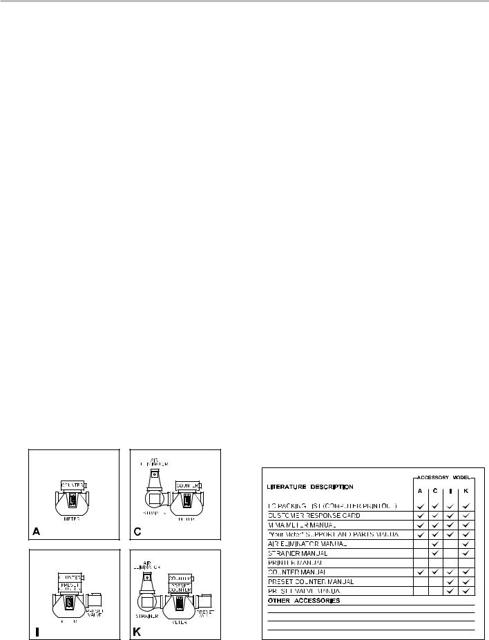
1. Check your owner’s information packet
LC meters come in many variations. The information sent to you depends on the accessories you have ordered with your meter. Make an inventory of your red Owner’s Information Packet. First, find your LC packing slip with the computer printout. Locate the serial number and the meter model number on this printout. Cross reference the packing slip number with the actual meter numbers. The illustration on following page will help you locate the Specification and Serial Number Plates on the meter and its accessories.
2. Record your meter serial number
Record your meter serial number and your full-service distributor’s name and telephone number in the space provided above. Save this information and keep it handy. When calling for service or parts, you will need to supply your meter serial number and model number. See How to Order Replacement Parts on page 23 for more information.
3. Identify your meter’s model-accessory letter.
Use the diagrams below to familiarize yourself with meter accessories. Find the meter and letter on the diagram which represents your meter system, then check with the chart below to see that your red owner’s information packet is complete. Not all accessory levels are available for every model of LC meter.
4. Make sure all documentation Is included with your meter
Check your red Owner’s Information Packet against the diagrams below to make sure that all the documentation needed for your meter and accessories is included in your packet. If documentation is missing, contact your full-service distributor or Liquid Controls or visit www.lcmeter.com where you can find the most up-to-date LC literature.
4

Serial Number Plate Locations
For components not pictured, refer to the components’ manual if you can not find the Serial Number Plate on the component.
5
How LC Meters Work
Liquid Controls meters are positive displacement meters. They are designed for liquid measurement in both custody transfer and process control applications. They can be installed in pump or gravity flow systems. Because of their simple design, they are easy to maintain, and easy to adapt to a variety of systems.
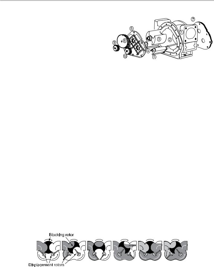
The meter housing (1) is designed with three cylindrical bores (2). Three rotors, the blocking rotor (3) and
two displacement rotors (4, 5), turn in synchronized relationship within the bores. The three rotors are supported by bearing plates (6, 7). The ends of the rotors protrude through the bearing plates. The blocking rotor gear (8) is placed on the end of the blocking rotor. The displacement rotor gears (9, 10) are placed on the ends of the displacement rotors. These gears create the synchronized timed relationship between the three rotors.
As fluid moves through the meter housing, the rotor assembly turns. The liquid is broken into uniform sections by the turning rotors. Fluid displacement occurs simultaneously. As fluid enters, another portion of the fluid is being partitioned and measured. At the same time, the fluid ahead of it is displaced out of the meter and into the discharge line. Since the volume of the bores is known, and the same amount of fluid passes through the meter during each revolution of the blocking rotor, the exact volume of liquid that has passed through the meter can be determined with a high degree of accuracy.
This true rotary motion is transmitted through the packing gland, the face gear, the adjuster drive shaft, and the adjuster to the register stack and counter. True rotary motion output means consistent accuracy since the register indication is in precise agreement with the actual volume throughput at any given instant.
At any position in the cycle, the meter body, the blocking rotor, and at least one of the displacement rotors form a continuous capillary seal between the unmetered upstream product and the metered downstream product.
Because the product is separated by the capillary seal,
Meter Element Exploded Line Drawing
no metal-to-metal contact is required within the metering element. This means no wear. No wear means no increase in slippage, and no increase in slippage means no deterioration in accuracy.
Throughout the metering element, the mating surfaces are either flat surfaces or cylindrical faces and sections that are accurately machined. These relatively simple machining operations, plus the fact that there is no oscillating or reciprocating motion within the device, permits extremely close and consistent tolerances within the LC meter.
The product flowing through the meter exerts a dynamic force that is at right angles to the faces of the displacement rotors. The meter is designed so that the rotor shafts are always in a horizontal plane. These two facts result in no axial thrust; therefore, LC meters do not need thrust washers or thrust bearings, the rotors automatically seek the center of the stream between the two bearing plates, eliminating wear between the ends of the rotors and the bearing plates. Once again, no wear results in no metal fatigue and no friction.
Liquid Controls meters are made of a variety of materials to suit a variety of products. Because of their no-wear design, capillary seals, and unique rotary metering, LC meters provide unequalled accuracy, long operating life, and unusual dependability.
6

Installation Requirements
▪Take all necessary safety precautions
Make sure that all necessary safety precautions have been taken. Provide for proper ventilation, temperature control, fire prevention, evacuation and fire management.
▪Provide access for fire extinguishers
Provide easy access to the appropriate fire extinguishers for your product. Consult with your local fire department and state and local codes to make sure that you are adequately prepared.
▪Read provided literature
Read this manual as well as all the literature provided in your red Owner’s Information Packet. If you have any questions, consult with your full-service distributor or call the Service Department at Liquid Controls.
▪Conform to all codes
Install the meter and accessories in conformance with applicable state and federal construction, electrical and safety codes.
▪Leave Thread Caps in Place
Before shipment, protective thread caps are placed in all meter and accessory openings. They should remain in place until you are ready to attach piping.
▪Flush Piping
Prior to meter installation, the entire piping system should be thoroughly flushed of all debris with a liquid that is compatible with the construction of the meter.
▪Keep external surfaces of the meter clean
▪Mount meter securely
The meter must always be securely bolted to a platform or supporting member, regardless of the mounting position of the meter. Never “hang” a meter on the connecting piping.
▪Prevent pipe strain or stress
Prevent pipe strain or stress from occurring when making meter or accessory repairs. Pipe strain and stress occurs when the pipes are not supported or are not aligned correctly to the meter. The weight of the pipes must always be supported independent of the meter. This means that the meter and accessories can be easily removed without affecting the pipes or the pipe alignment. Never leave any of the pipes hanging.
▪Install meter only on the discharge side (downstream) of the system pump
▪Apply pipe compound to male threads only
▪Leave space for future maintenance
Position the meter with service in mind. Provide ample work space. Removing covers can be difficult when work space is not available.Always supply a platform or support for the meter mounting.
▪Use meter only with specified liquids
Ameter is metallurgically designed to be physically compatible with the type of liquid originally specified by the customer, and as indicated on the Serial Number Plate.Ameter should not be used with a liquid different from the liquid originally specified, unless the physical characteristics and pH rating are similar and the application has been checked with LC Sales and Engineering through your full-service distributor.
! WARNING
Under normal operation, do not expose any portion of the LP-Gas system to pressures in excess of rated working pressures without an automatic safety valve to vent the over pressure discharge to a place of safety away from the operator and other people.
Failure to provide such a safety relief may result in leakage or rupture of one or more of the components in the system. This can result in injury of death from the gas, a fire, or pieces of flying debris from the rupture.
Class 10 LPG Meters - Codes
Class 10 LPG meters must be installed in accordance with the requirements of ANSI-NFPA 58 in addition to all other state and local codes.
▪Install a strainer
Install a strainer on the meter inlet to avoid damage from foreign matter, such as weld slag, from entering the system. The strainer must always be located on the inlet side.
▪Tag flow direction
All meters are tagged identifying their direction of flow. Meters are set with a flow direction of left to right as standard. However, when a meter is ordered, the customer can specify that the flow be set from either direction. If the meter register counts in reverse, the meter is reading the direction of flow in reverse. If this occurs, the meter registration must be reset. For mechanical output meters, see Reversing the Meter Registration on page 10. For electrical output meters, such as meters equipped with a pulser or an electronic register, refer to the manual of the electronic component.
▪Use current engineering drawings
Always request up-to-date, engineering approved, dimensional drawings before starting any construction. Do not rely on catalog pictures or drawings. They are for reference only.After receiving prints, check to see that all equipment ordered is shown and that any extra pressure taps, plugs, etc. are noted and their size specified.
7

Operation Requirements
▪The meter must remain full of product at all times.
An easy way to accomplish this is to put the meter assembly in the line below the piping center-line (a sumped position). This requires adding elbows and flanges prior to installing the meter. The meter should be installed in a bypass loop, below the pipe center-line, with block valves upstream and downstream of the meter inside the bypass loop.Ablock valve should be located in the main pipeline and labeled as the bypass valve.
▪Piping pressure relief
Any portion of pipe system that might isolate or block flow should be provided with a pressure relief to prevent damage from thermal expansion. There are excellent benefits to this type of installation. First, the meter is kept full. Second, this type of installation allows the meter to be isolated for servicing and calibration while continuing flow through the bypass valve.
▪Maintain upstream lines
Upstream lines must be maintained full to prevent air from entering the meter. If upstream or inlet lines are constructed in a manner which allows reverse flow, foot valves, or back checks must be installed.
▪Underground tanks, submersible pumps
Underground tanks that are furnished with a submersible pump will eliminate many problems that occur with positive displacement pumps (suction pumps) when suction piping is incorrectly sized or when the lift is too great.
▪API Manual of Petroleum Measurement Standards
Every meter should be calibrated under actual service and installation conditions per theAPI Manual of Petroleum Measurement Standards:
The following chapters of theAPI Manual of Petroleum Measurement
Standards supersedes theAPI standard 1101.
Chapter 4 - Proving Systems
Chapter 5 - Metering
Chapter 6 - MeteringAssemblies
Chapter 11 Section 2.3 - Water Calibration of
Volumetric Provers
Chapter 12 Section 2 - Calculation of Petroleum
Quantities
▪Provide a means of conveniently diverting liquid for calibration purposes
▪Evaluate pumping equipment
Give careful attention to your system’s pumping equipment and piping. Because of their influence on liquid being measured as it enters the metering assembly, systems should be made free of conditions that cause or introduce entrained air or vapor.
▪Follow the manufacturer’s recommendation fully when installing pumps
Give particular attention to factors like: use of foot valves, pipe size to the inlet, and conformance to net positive suction head (NPSH) conditions when suction pumping is required. Follow the manufacturer’s recommendations to minimize air and vapor elimination problems.
▪Light hydrocarbons and similar liquids
For liquids such as light hydrocarbons that tend to flash or vaporize easily at higher ambient temperatures, it is advantageous to use flooded suctions and piping sized larger than the nominal pump size.
▪Vehicle tank installations
On vehicle tank installations, the layout of the system’s piping is crucial in preventing problems with split compartment test conformance. Piping should slope away from a positive
displacement pump to prevent resurgent re-priming of the pump due to drain back.
▪Avoid hydraulic shock
Hydraulic shock is harmful to all the components of an operating system, including the valves, the meter, and the pump. Because of the high precision with which they measure products, meters, in particular, must be protected against hydraulic shock. The best protection against hydraulic shock is to prevent it from occurring. To prevent hydraulic shock, adjust the closing rate of the valve until shock does not occur.
▪Avoid thermal expansion
Thermal expansion, like hydraulic shock, can easily damage meters and other components in the system. When designing the system, include pressure relief valves in any portion or branch of the system that might be closed off when an operating or block valve is closed.
8

Meter Start Up and Operation
Prior to meter start up, use extreme caution. Make sure that:
1. The meter is properly secured
2. All connections are tight
3.All valves are in the closed position
Placing your meter in operation
When placing your meter in operation, the meter and system must be filled slowly with liquid and be free of air prior to start-up. Extreme care must be taken to avoid damaging the meter during this time. When filling the system with liquid for the first time, gravity filling is the preferred method of filling the system with liquid. Gravity filling uses positive head
pressure from product storage above the inlet port of the meter to fill the system. with the pump.
To fill the meter and system with liquid:
1.Make sure all valves (upstream and downstream of the meter) in the system
are closed.
2.Open the valve located at the storage tank a small amount. Provided there is not a valve between the tank and the meter inlet, the meter’s register/counter
will start to move and then stop. If there is another valve between the tank and meter, repeat this process with each valve until the meter is exposed to the liquid.
3.Once you are assured that the meter has registered some volume and stopped, continue to open the tank valve until it is completely open.
4.With the valve(s) open between the tank and the meter, slowly open the downstream valve until the meter’s register/counter starts to move. Do not run the meter any faster than 25% of its rated flow during start-up. Once the product is flowing out of the end of your system, the outlet valve can be opened all the way, provided that the system is designed not to exceed the flow rate marked on the meter.
▪Never operate the meter or system when partially filled with liquid, or with pockets of compressed air or vapor present.
If these conditions cannot be avoided, air and vapor elimination systems may be required. If you cannot fill the meter slowly by gravity or by using a valve to throttle back the flow, consult the factory.
▪Do not operate the meter above the Maximum Pressure Listed on the Serial Number Plate.
Under any and all pressure producing circumstances (for instance, thermal expansion and hydraulic shock) the working pressure must not exceed the maximum pressure indicated on the Serial Number Plate.
▪Do Not Operate the Meter Above the Maximum FlowRate Listed on the Serial Number Plate
If the meter is operated at a rate greater than the maximum recommended GPM, excessive wear and premature failure may occur.
▪The meter can be calibrated for flows below minimum ratings
If the flow remains constant and varies within narrow limits or if the product is viscous, the meter can be calibrated for flows below minimum ratings. If the meter is installed in a custody transfer application (for financial transactions), the flow rate must fall within flow rate range indicated on the serial number plate.Ameter should never be run beyond the maximum flow rate determined for that class meter and/or liquid measured.
! WARNING
Before disassembly of any meter or accessory component:
•All internal pressures must be relieved and all liquid drained from the system in accordance with all applicable procedures.
•Pressure must be 0 (zero) psi.
•Close all liquid and vapor lines between the meter and liquid source.
For Safety Rules, refer to local authorities and relevant NFPA Codes.
Failure to follow this warning could result in property damage, personal injury, or death from fire and/or explosion, or other hazards that may be associated with this type of equipment.
9
 Loading...