


CONTENTS
Specifi cations |
|
Battery Installation and Replacement |
2 |
Dimensions |
3 |
Theory of Operation |
4 |
Wiring |
4 |
Typical Applications |
4 |
Defi nitions |
5 |
Programming Flowchart |
8 |
Operation |
10 |
Error Messages |
11 |
Analog Output Calibration |
11 |
IT300-W Drawing |
12 |
IT300-N Drawing |
13 |

SPECIFICATIONS
Description
Featuring5digitsofrateand8digitsoftotal,theIT300N isabattery or loop powered indicator capable of accepting magnetic pickup, DC pulse or switch closure inputs from pulse producing fl owmeters.
The IT 300N uses the 4-20mA loop to provide power.
Specifi cations
Power:
BATTERY POWERED
Supplied with 2 C size Lithium battery pack. EXTERNAL POWER INPUT
Voltage: 8.5 to 30 VDC Current: Less than 5 mA
Protection: Reverse Polarity Protection on DC Power Input LOOP POWERED
Voltage: 8.5 to 30 VDC
Protection: Reverse Polarity Protection on Current Loop
Loop Burden: 8.5V maximum
BATTERY LIFE EXPECTANCY:
Expected Years of Operation for IT 300N of various powering options at equipment duty cycles
MODEL |
|
RUN TIME |
|
|
|
Idle |
2hrs/day |
8hrs/day |
24hrs/day |
IT 300N-A |
10 yrs |
10 yrs |
10 yrs |
9.1 yrs |
IT 300N-A-4 |
10 yrs |
10 yrs |
10 yrs |
8.4 yrs |
IT 300N-B/C |
10 yrs |
10 yrs |
10 yrs |
10 yrs |
standby-operation |
|
|
|
|
IT 300N -B/C |
Indefi nite operation when externally powered |
|||
loop power |
|
|
|
|
NOTE: Battery shelf life is rated at 10 years by manufacturer Life expectancy based on rated battery capacity at 20°C
The above table is shown with pulse output inactive.
Use of pulse output shortens battery life.
Example: A pulse output of 0.06 sec. duration, once per second, would derate the battery life by 20%.
DISPLAY:
Rate Display: (selectable decimal)
5 Digits (99999), 0.35" High, Display updates once per second with battery power, 8X per second with DC or Loop power
Rate Descriptors: |
/SEC, /MIN, /HR |
|
/MIN, /HR, /DAY with "D" option |
Min. Input Frequency: 0.01 Hz to 10 Hz (selectable delay of 0.1 to 99.9 seconds)*
Selectable Rate Display Damping Totalizer Display: (selectable decimal)
8 Digits (99999999), 0.2" High
Totalizer Descriptors: GAL, LIT, FT3, M3, "blank"
GAL, BBL, MCF, M3, "blank" with "D" option
Warning Displays: Low battery warning
PULSE OUTPUT:
The pulse output advances with the least signifi cant digit of the totalizer or decimal multiples there of (see Pulse scale divider).
Type: Isolated photomos relay
Max. voltage (off state): 30 VDC Current (on state): 100mA
Pulse Duration: Selectable 0.5, 0.25, 0.125, 0.0625 seconds Pulse Scale divider (Pulscale): User selectable, ÷1, ÷10, ÷100 or OFF
NOTE: Select OFF for max. battery life.
ACCURACY
0.01% Reading, ±1 count
Temperature Drift: 50 ppm/°C Worst Case
ENVIRONMENTAL:
OPERATING TEMPERATURE -22°F (-30°C) to + 158°F (70°C)
HUMIDITY
0 - 90% Noncondensing
INPUTS:
MAGNETIC PICKUP INPUT
Frequency Range: 0 to 3500 Hz
Trigger Sensitivity: 10 mV p-p Over Voltage Protected: ± 30 VDC
OPTO-ISOLATED DC PULSE INPUT High (logic 1): 4-30 VDC
Low (logic 0): Less Than 1 VDC Minimum Current: .5 mA Hysteresis: 0.4 VDC
Frequency Range: 0 to 5 kHz Min. Pulse Width: 0.1 msec
CONTACT CLOSURE INPUT (contact closure to common) Internal Pullup Resistor: 100 KΩ to +3.6 VDC
High (logic 1): Open or 4-30 VDC Low (logic 0): Less Than .5 VDC
Internal Switch Debounce Filter: 0 to 40 Hz NOTE: Sustained contact closure will shorten
battery life.
RESET INPUT (contact closure to common) Internal Pullup Resistor: 100 KΩ to +3.6 VDC High (logic 1): Open or 4-30 VDC
Low (logic 0): Less Than .5 VDC Minimum On : 25 msec
NOTE: Sustained contact closure will shorten battery life.
K-FACTOR
Range: 0.001 to 99999999
Decimal Point Locations: XXXX.XXXX to XXXXXXXX
20 Point Linearization Option
This feature allows the user to enter 20 different frequencies with 20 different corresponding K-Factors to linearize non linear signals.
ANALOG OUTPUT:
Type: 4-20 mA follows rate display, Two wire hookup Accuracy: 0.025% Full Scale at 20° C
Temperature Drift: 50 ppm/°C Typical
Reverse Polarity Protected
Update Rate: 8 times/second
NOTE: The IT 300N uses the 4-20 mA loop power as its primary power source when this option is used. The battery is still required for standby battery operation.
DATA STORAGE:
Setup Information: Stored in fl ash memory
Totalizer: Stored in battery backed RAM but can be saved to fl ash memory by operator for recall after battery change out.
*Slow input pulse rates, large delay setting and internal math operations may delay the update rate of information.
BATTERY INSTALLATION and REPLACEMENT
Battery Installation:
All meter mounted confi gured IT 300N models are shipped without the batteries installed. When using external BATPACK, mount within 12" and plug connector into 3 position square posts (see Fig 1). Polarity is not a concern because center is common.
To install the batteries, begin by locating the battery holder. This requires opening the enclosure cover and removing the IT 300N to expose the battery holder.
The plus terminal of the battery is marked with a (+) symbol stamped into the battery holder. Be sure to install the batteries correctly.
Install batteries to begin setup procedure. See Programming Flowchart to setup desired operating parameters.
Battery Replacement:
The IT 300N has a battery monitor feature which illuminates when the lithium battery voltage approaches its end of life. A descriptor, “BAT”, illuminates when the battery voltage falls below this predetermined value. The low battery detector operates correctly with all power options.
The battery, or batteries, should be replaced within several weeks of the fi rst occurrence of low battery warning, “BAT”. Left unattended, the unit may become inaccurate, cease to operate or malfunction.
Before replacing the battery(ies), Press the (left arrow) key to save the totalizer. The display will show "SAVE TOTAL". This will save the current total value and the total will resume from this value when the new battery(ies) is(are) installed. NOTE: If the display starts to fl ash after the "SAvEtotAL" message times out, press the "E" (enter) key. If the message "E FLASH" is displayed, then there was not enough power left to save the setup and totalizer to fl ash memory. At this point you must record the totalizer and setup information and re-enter the setup data after the new battery(ies) is(are) installed.
Install new battery(ies) as described above.
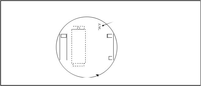
Fig 1
Rear View
BATPACK
Connector
7 8 9 101112
Battery
6 5 4 3 2 1
 Jumper momentarily to reset unit to factory default values.
2

DIMENSIONS
Fig 1
|
2.093 |
|
|
(53) |
1.10 |
|
1.75 |
|
|
(28) |
|
|
(44.5) |
|
|
|
|
2.125 |
|
1.0 |
(54) |
|
(25.4) |
Mounting
Holes
3
 Loading...