


HML110
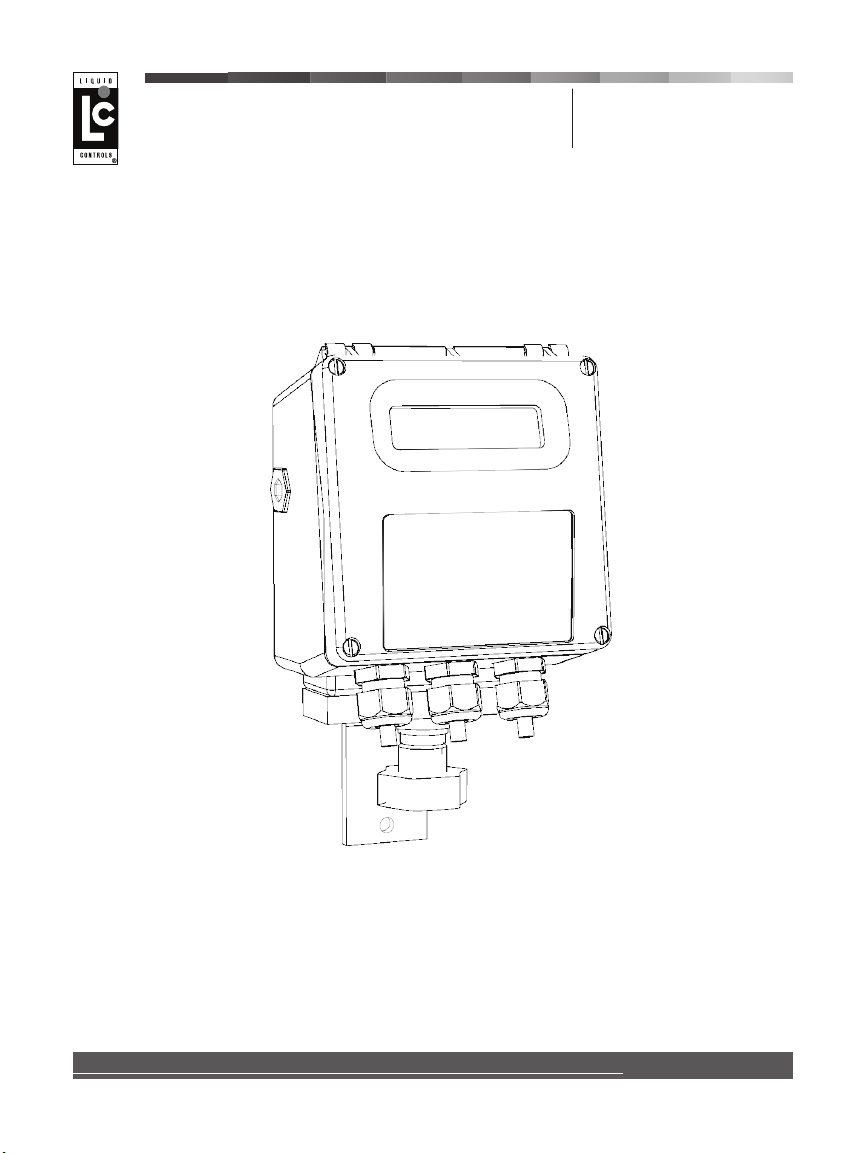
HML110 Converter
LCMag Electromagnetic Flowmeters
Installation &
Operation
Release number: 110_EN_LC_5_3_6X
The last three digits of le name identify the software version which the manual refers to;
it is visualized at the instrument start up, or by specic function on DIAGNOSTIC menu.
Liquid ControLs Group
An IDEX Fluid & Metering Business
IEM200-11

HML 110
CONTENTS
INTRODUCTION ............................................................................................ 3
SYMBOLS USED IN THIS MANUAL .................................................................. 3
TECHNICAL CHARACTERISTICS....................................................................... 4
INPUT/OUTPUT ISOLATION ............................................................................ 4
ENVIRONMENTAL COND ITIONS OF USE .......................................................... 4
OPERATING TEMPERATURE ............................................................................ 4
DIMENSIONS ( HOUSING IN NYLON ).............................................................. 5
DIMENSIONS ( HOUSING IN ALUMINUM ) ....................................................... 6
ELECTRICAL CONNECTIONS............................................................................ 7
GROUNDING INSTRUCT IONS .......................................................................... 7
CONVERTER POWER SUPPLY........................................................................... 7
INTERNAL VIEW OF CONVERTER .................................................................... 8
CONVERTER TO SENSOR E LECTRICAL CONNECTIONS...................................... 8
DIGITAL INPUT ............................................................................................ 10
OPERATION ON INPUT ON/OFF.................................................................... 10
OUTPUTS WIRING ........................................................................................ 11
DISPLAY FLAGS AND LED WARNING INTERPRETATION.................................. 12
ACCESS TO THE CONVERTER KEYPAD........................................................... 13
ACCESSING THE CONVERT FUNCTIONS AT START- UP (Powe r On).................. 14
Example of visualized display pages at start-up............................................... 14
FLOW RATE VISUALIZATION......................................................................... 15
CONVERTER FUNCTION SETTING ACCESS CODES.......................................... 16
ACCESS TO THE CONFIGURATION MENUES................................................... 16
EXAMPLE: “Quick start menu” function modification. Full scale value 1 (Fs1) from
4dm³/s to 5dm³/s......................................................................................... 17
EXAMPLE: “Main menu” function modification. Full scale value 1 (Fs1) from 4dm³/s
to 5dm³/s. (Quick start menu enabled) .......................................................... 18
MAIN MENU GROUPS AND FUNCTION DESCRIPTIO NS .................................... 19
MAIN MENU FUNCTION PRGRAMMING .......................................................... 22
ALARM MESSAGES, CAUSES AND CORRECTIVE ACTIONS................................. 28
ANOMOLY CODES......................................................................................... 28
2
110_EN_LC_5_3_6X.doc
INTRODUCTION
A
K
This manual is an integral part of the product. Read carefully the instructions contained,
they give important indications for it’s safe use and maintenance. Technical information
and related products in this manual may undergo modifications without prior notice.
The flow meter must be used within the specified limits. The improper use, possible
tampering, or substitutions of one or any of the original components renders the
manufacturers warranty void with immediate effect. The manufacturer accepts
responsibility only if the instrument it’s used within the published or prior agreed
specification.
Reproduction of this manual and any software supplied with this
converter is strictly forbidden.
SYMBOLS USED IN THIS MANUAL
TTENTION
DANGER ELECTRIC SHOC
WARNING
PRECAUTIONS
HML 110
3
110_EN_LC_5_3_6X.doc
g
)
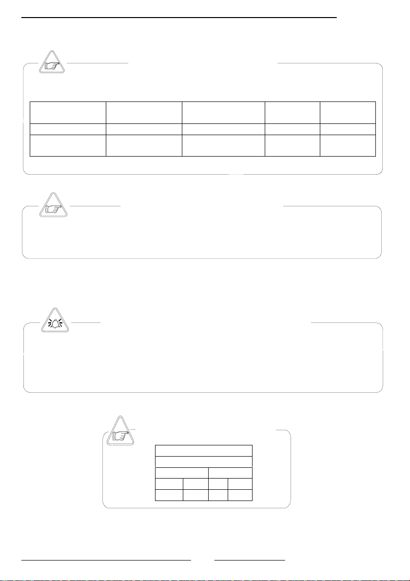
TECHNICAL CHARACTERIST ICS
ELECTRIC CHARACTERISTICS
Classification of the converter: class I, IP 65, category of installation II
Power supply
versions
HV 90-265 Vac 44 - 66 Hz 3W/5VA 35 mA
LV
Power supply
voltage
12-60 Vdc
18-45 Vac
INPUT/OUTPUT ISOLATION
Input/output insulated up to 500V
The output 4-20 mA and output 24 Vdc are electrically connected
The converter can be installed internally or externally with in the following specification
Altitude: from –200 to 6000 m (from -656 to 19685 feet)
Humidity range: 0 - 98%
Line volta
ENVIRONMENTAL CONDITIONS OF USE
e range: (see table of Electrical Characteristics above
OPERATING TEMPERATURE
Ambient Temp.
Min. Max
°C °F °C °F
-10* -14* 50 122
* In situations of discontinuous use in cold ambient temperatures, the
installation of an additional heat source may be necessary.
Power supply
frequency
Pmax
0 - 44 - 66 Hz 3W/5VA 300 mA
CONVERTER
current
max
HML 110
4
110_EN_LC_5_3_6X.doc
HML 110
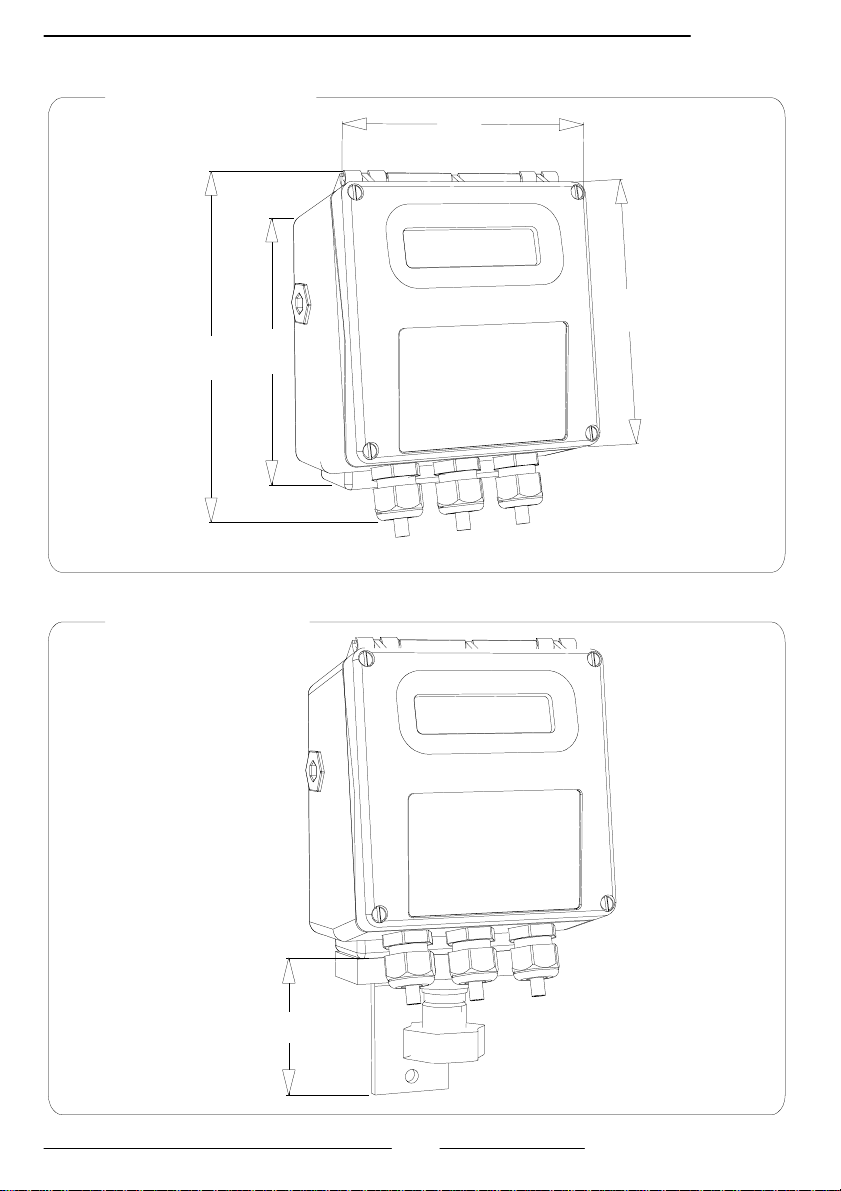
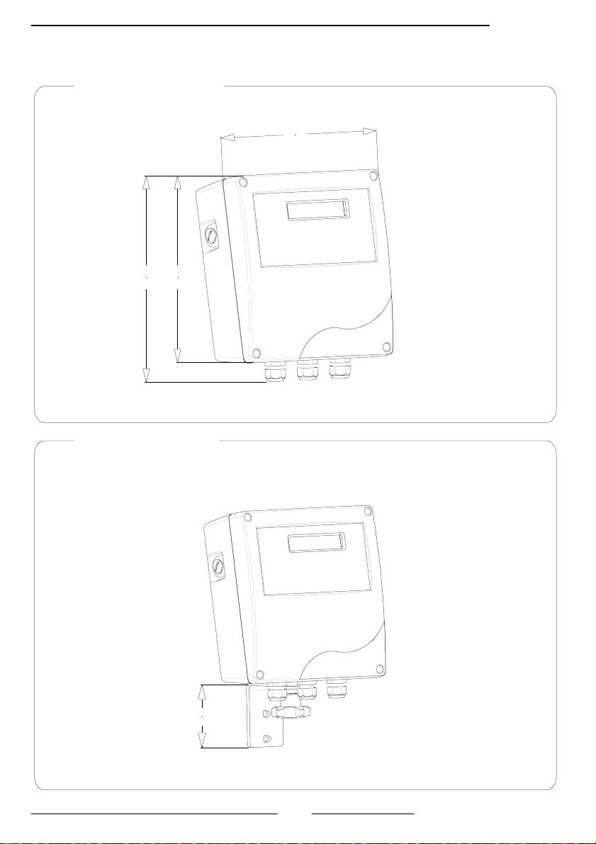
DIMENSIONS ( HOUSING IN NYLON )
COMPACT VERSION
168
SEPARATE VERSION
129
78
1
2
7
4
2
1
5
110_EN_LC_5_3_6X.doc
HML 110
DIMENSIONS ( HOUSING IN ALUMINUM )
COMPACT VERSION
0
6
1
193
169
SEPARATE VERSION
78
6
110_EN_LC_5_3_6X.doc
ELECTRICAL CONNECTIONS
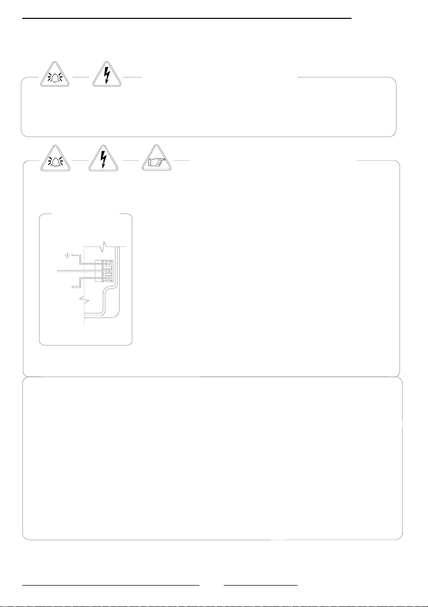
GROUNDING INSTRUCTIONS
ALWAYS ensure that the Converter and the Sensor are grounded (earthed) correctly.
The grounding of t he sensor and converter ensures th at the equipment and liquid are
equipotential.
CONVERTER POWER SUPPLY
L
(-)
N
(+)
Before connecting the power supply, verify that the
mains voltage falls between the limits indicated on
the tag plate.
ATTENTION: Converters on a dc power supply line
are not protected against the inversions of p o larity.
When wiring the converter and sensor equipme nt use
only approved conductors, with fire- proof p r op erties.
The power supply line must be equipped with an
external protection for current overload (fuse or
automatic line breaker, limiting current to less than
10 A).
Provide in close proximity to the converter a circuit
breaker that must be easily accessible to the operator
and clearly identified.
NOTE: For characteristics of the converter’s power
supply, see page 4
The sensor, hardwired inputs and outputs are connected to the converter
through a terminal block locate inside the converter.
To locate the terminal block loosen the 4 screws on the front cover. Lift the
front panel. With the front cover lifted, the terminal block is visible. The
terminal block is the hardwire connection of the converter to external
equipment, including the sensor.
The following pages give information on the terminal block numbering, and the
respective connecting of the senor cables, and input/outputs.
HML 110
7
110_EN_LC_5_3_6X.doc

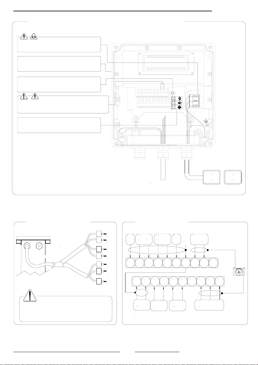
INTERNAL VIEW OF CONVERTER
Power supply
IF2 socket
Signalling LED:
See interpretation notes page 12
Dangerous voltage on block 12-13:
- 60 Vdc Max
- 250 V Max on commutation coils (switching )
Keyboard
CONVERTER TO SENSOR ELECTRICAL CONNECTIONS
SEPARATE VERSION
C018 CABLE
1
2
3
4
11
12
13
E1
E2
C
SH
B1
B2
Sudden movements to the electrodes
cable can cause noise during
measurement Max length of
electrodes cable: 20 m
11 12 13 14 15 16 17 18 19 20
TERMINAL BLOCK
OUT2
24V
-
E C
E C
10
-
+
A
4-20mA
RS 485* : OPTIONAL
RS 485* INPUT
12345678910
OUT1
B
24V
-
+
Power supply
>HV<
90..265VAC
SC
B2
+
SC
HML 110
>LV<
15...45VAC
10...63VDC
COILS
SC
B1
11121314151617181920
C
E2
ELECTRODES
123456789
E1
8
110_EN_LC_5_3_6X.doc
R
INTERNAL VIEW OF THE ALUMINUM CONVERTE
Power supply
IF2 socket
Signalling LED:
See interpretation notes page 10
Dangerous voltage on block 12-13:
- 60 Vdc Max
- 250 V Max on commutation coils (switching )
Keyboard
Shield
C018 cable
ALUMINIUM CONVERTER TO SENSOR, ELECTRICAL CONNECTIONS
SEPARATE VERSION TERMINAL BLOCK M1
1
C018 CABLE
2
3
S
S
12
13
E1
E2
C
SH
SH
B1
B2
24V
-
10
OUT2
E
OUT1
24V
+
E
C
C
SC
Sudden movements to the
electrodes cable can cause noise during
measurement Max length of
electrodes cable: 20 m
-
+
A
4-20mA
RS 485* INPUT
RS 485* : OPTIONAL
-
B
+
>HV<
90..265VAC
COILS
B1
B2
C
ELECTRODES
HML 110
Power supply
>LV<
15...45VAC
10...63VDC
11121314151617181920
123456789
E1
E2
9
110_EN_LC_5_3_6X.doc

DIGITAL INPUT
A
External power supply Internal power supply
10 K
5 (+)
3/40 Vdc (ON)
0/1,5 Vdc (OFF)
6 (-)
10 K
+24
15
5
6
0
20
OPERATION ON INPUT ON/OFF
uto-calibration
AUTOCALIB. OFF
3-40 V
Tmin<T<1sec. = autocalibr ation
T > 1 sec. = Auto zero
Necessary conditions for enabling the function
POS. 5.7 ENABLED (Autozero calibration external command)
0-1,5 V
T
Reset totalizes
3-40 V
0-1,5 V
BLOCK
T
RESET
Tmin = 100ms
Necessary conditions f or en abling the function
POS. 5.1 to 5.4 ENABLED (partial positive or reverse
flow totalise reset enable).
Block totalizes
Block totalizes
3-40 V
Necessary conditions f or en abling the function
POS. 5.6 ENABLED (totalise counting lock command)
0-1,5 V
Totalizers active
Range change
3-40 V
Scale 2
0-1,5 V
Scale 1
Necessary conditions f or en abling the function
POS. 5.8 ENABLED (range change)
SAMPLE RAT E
10 Hz
20 Hz
50 Hz
Tmin
220 ms
110 ms
45 ms
SAMPLE RATE
80 Hz
150 Hz
Tmin
30 ms
T must be > to Tmin
15 ms
HML 110
10
110_EN_LC_5_3_6X.doc
 Loading...