


 Installation & Parts Manual
 K-7, K-15, & K-30
Air Actuated & Differential Check Valves
|
|
|
|
|
|
|
|
|
|
|
|
|
|
|
|
|
|
|
|
|
|
|
|
|
|
|
|
|
|
|
|
|
|
|
|
|
|
|
|
|
|
|
|
|
|
|
|
|
|
|
|
|
|
|
|
|
|
|
|
|
|
|
Installation: M400-30 |
www.lcmeter.com |
|
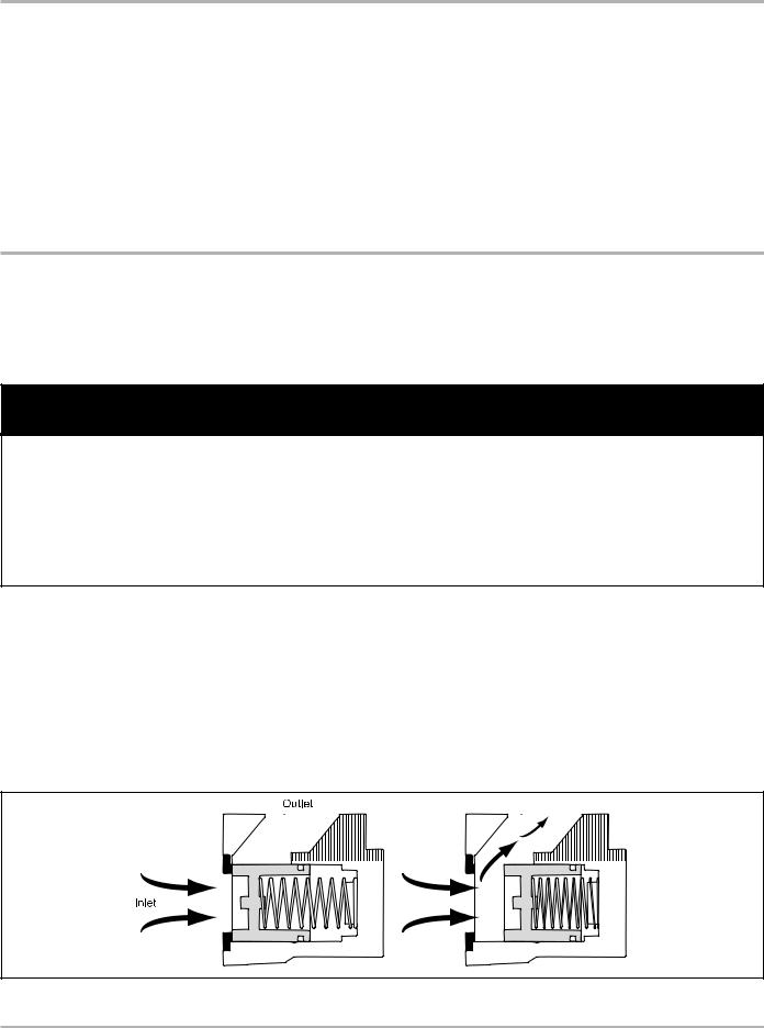
Table of Contents
Description |
Page Number |
Description |
Page Number |
General Information .................................................. |
2 |
Disassembly and Reassembly |
.................................. 7 |
Specifications ............................................................ |
3 |
K-30 Valves ............................................................... |
8 |
K-7 Valves ................................................................. |
4-5 |
Installation ................................................................. |
8 |
Installation ................................................................. |
4 |
New Installations ....................................................... |
8 |
New Installations ....................................................... |
4 |
Retrofit Installations ................................................... |
8 |
Retrofit Installations ................................................... |
4 |
Illustrated Parts Breakdown ...................................... |
9-11 |
Disassembly and Reassembly .................................. |
5 |
K-7 Valves ................................................................. |
9 |
K-15 Valves ............................................................... |
6-7 |
K-15 Valves ............................................................... |
10 |
Installation ................................................................. |
6 |
K-30 Valves ............................................................... |
11 |
New Installations ....................................................... |
6 |
|
|
Retrofit Installations ................................................... |
6 |
|
|
Publication Updates and Translations
The most current English versions of all Liquid Controls publications are available on our website, www.lcmeter.com. It is the responsibility of the Local Distributor to provide the most current version of LC Manuals, Instructions, and Specification Sheets in the required language of the country, or the language of the end user to which the products are shipping . If there are questions about the language of any LC Manuals, Instructions, or Specification Sheets, please contact your Local Distributor.
!WARNING
•Before using this product, read and understand the instructions.
•Save these instructions for future reference.
•All work must be performed by qualified personnel trained in the proper application, installation, and maintenance of equipment and/or systems in accordance with all applicable codes and ordinances.
•Failure to follow the instructions set forth in this publication could result in property damage, personal injury, or death from fire and/or explosion, or other hazards that may be associated with this type of equipment.
General Information
Liquid Controls Air Actuated/Differential Check Valves are designed to prevent flow whenever air or vapor is present, thereby assuring accurate measurement.
Check Valves are normally closed, spring loaded valves installed on the meter outlet. When fluid enters the valve from the inlet side, and the pressure is greater than the back pressure combined with the force of the spring, the spring will compress, opening the valve and allowing fluid
to pass through (as shown in the figure below).
When back pressure plus spring strength is greater than the fluid pressure entering the meter, the valve will remain closed.
These meters are used in conjunction with the air/vapor eliminator to prevent air/vapor from being metered. This is important when split compartment testing.
K-7 Valve Operation
2

|
|
|
|
Specifications |
|
Model/Applications |
|
|
|
||
|
|
|
|
||
|
Used on M-5 & M-7 - 1½" & 2" Meters |
|
|
||
K-7 Valves: |
Maximum Flow Rate = 150 gpm (568 lpm) |
|
|||
|
Working Pressure: 150 psi (10.5 bar) |
|
|
||
|
|
|
|
|
|
Model No. |
Material |
Spring |
Seals |
Applications |
|
|
|
|
|
|
|
A2811 |
Cast Iron |
Standard |
Viton |
Chlorinated Solvents |
|
|
|
|
|
|
|
A2817 |
Aluminum |
Standard |
Viton |
Petroleum Products |
|
|
|
|
|
|
|
A28171 |
Aluminum |
Medium |
Viton |
Petroleum Products |
|
|
|
|
|
|
|
A28172 |
Aluminum |
Heavy Duty |
Viton |
Petroleum Products |
|
|
|
|
|
|
|
A2821 |
Aluminum |
Standard |
PTFE |
Liquid Sweeteners, Methanol |
|
|
|
|
|
|
|
A2826 |
Aluminum |
Standard |
Viton |
Liquid Sweeteners |
|
|
|
|
|
|
|
A2831 |
Cast Iron |
Standard |
PTFE |
Caustics |
|
|
|
|
|
|
|
A2851 |
Aluminum |
Standard |
EPT |
NH3 Applications. |
|
A2862 |
Stainless Steel |
Standard |
PTFE |
Acidic PH Liquids |
|
|
|
|
|
||
|
|
|
|
||
|
Used on M-15 & M-25 - 3" Meters |
|
|
||
K-15 Valves: |
Maximum Flow Rate = 300 gpm (1,136 lpm) |
|
|||
|
Working Pressure = 150 psi (10.5 bar) |
|
|
||
|
|
|
|
|
|
Model No. |
Material |
Spring |
Seals |
Applications |
|
|
|
|
|
|
|
A3830 |
Aluminum, |
Standard |
Viton |
Aviation Fuels |
|
Aluminum Guide |
|||||
|
|
|
|
||
|
|
|
|
|
|
A3845 |
Aluminum, |
Standard |
Viton |
Petroleum Products |
|
Bronze Guide |
|||||
|
|
|
|
||
|
|
|
|
|
|
Used on M-30 - 3" Meters
K-30 Valve: Maximum Flow Rate = 300 gpm (1,136 lpm)
Working Pressure = 150 psi (10.5 bar)
Model No. |
Material |
Spring |
Seals |
Applications |
A4845 |
Aluminum |
Standard |
Viton |
Petroleum Products |
K-15 & K-30 Valves
K-7 Valves
3

K-7 Valves
New Installations
When ordered with a new metering system, the Check Valve is supplied mounted to the metering system as shown to the right. A line must be connected to the flange on the outlet side of the 2-stage, preset valve. This flange connection is 2” NPT.
Finally, install a vent line from one port of the check valve to the air eliminator. Plug the other side of the check valve.
Retrofit Installations
Depending on the existing configuration, adding a Check
Valve may require modification of the outlet piping.
After the internal pressure is relieved from the system, the output line can be disconnected from the output side of the meter. If the system includes an electronic, 2- stage, preset valve, remove it from the meter. The check valve assembly can then be connected to the output side of the meter.
Use the four bolts and washers to fasten the valve assembly to the meter. The valve has an arrow showing the direction of flow. Ensure that the valve is properly oriented.
Tighten the bolts in a crossing pattern. Once the check valve is secure, the electronic, 2-stage, preset valve can be connected to the back check valve as shown to the right. Once this is complete, the output piping may be reconnected to the electronic, 2-stage, preset valve. The preset valve output fitting is 2” NPT.
Run a line from one port of the check valve to the air eliminator. Plug the other side of the check valve.
!WARNING!
Before disassembly of any meter or accessory component, ALL INTERNAL PRESSURES MUST BE RELIEVED. Pressure must be 0 (zero) psi. Close all liquid and vapor lines between the meter and liquid or gas pressure source (such as the supply tank, discharge lines and supply lines).
4
 Loading...