


 Installation and Parts Manual
LectroCount LCR
|
|
|
|
|
|
|
|
|
|
|
|
|
|
|
|
|
|
|
|
|
|
|
|
|
|
|
|
|
|
|
|
|
|
|
|
|
|
|
|
|
|
|
|
|
|
|
|
|
|
|
|
|
|
|
|
|
|
|
|
|
|
|
|
|
|
|
|
|
|
|
|
|
|
|
|
|
|
|
|
|
|
|
|
|
|
|
|
|
|
|
|
|
|
|
|
|
|
|
|
|
|
|
|
|
|
|
|
|
|
|
|
|
|
|
|
|
|
|
|
|
|
|
|
|
|
|
|
|
|
|
|
|
|
|
|
|
|
|
|
|
|
|
|
|
|
|
|
|
|
|
|
|
|
|
|
|
|
|
|
|
|
|
|
|
|
|
|
|
|
|
|
|
|
|
|
|
|
|
|
|
|
|
|
|
|
|
|
|
|
|
|
|
|
|
|
|
|
|
|
|
|
|
|
|
|
|
|
|
|
|
|
|
|
|
|
|
|
|
|
|
|
|
|
|
|
|
|
|
|
|
|
|
|
|
|
|
|
|
|
|
|
|
|
|
|
|
|
|
|
|
|
|
|
|
|
|
|
|
|
|
|
|
|
|
|
|
|
|
|
|
|
|
|
|
|
|
|
|
|
|
|
|
|
|
|
|
|
|
|
|
|
|
|
|
|
|
|
|
|
|
|
|
|
|
|
|
|
|
|
|
|
|
|
|
|
|
|
|
|
|
|
|
|
|
|
|
|
|
|
|
|
|
|
|
|
|
|
|
|
|
|
|
|
|
|
|
|
|
|
|
|
|
|
|
|
|
|
|
|
|
|
|
|
|
|
|
|
|
|
|
|
|
|
|
|
|
|
|
|
|
|
|
|
|
|
|
|
|
|
|
|
|
|
|
|
|
|
|
|
|
|
|
|
|
|
|
|
|
|
|
|
|
|
|
|
|
|
|
|
|
|
|
|
|
|
|
|
|
|
|
|
|
|
|
|
|
|
|
|
|
|
|
|
|
|
|
|
|
|
|
|
|
|
|
|
|
|
|
|
|
|
|
|
|
|
|
|
|
|
|
|
|
|
|
|
|
|
|
|
|
|
|
|
|
|
|
|
|
|
|
|
|
|
|
|
|
|
|
|
|
|
|
|
|
|
|
|
|
|
|
|
|
|
|
|
|
|
|
|
|
|
|
|
|
|
|
|
|
|
|
|
|
|
|
|
|
|
|
|
|
|
|
|
|
|
|
|
|
|
|
|
|
|
|
|
|
|
|
|
|
|
|
|
|
|
|
|
|
|
|
|
|
|
|
|
|
|
|
|
|
|
|
|
|
|
|
|
|
|
|
|
|
|
|
|
|
|
|
|
|
|
|
|
|
|
|
|
|
|
|
|
|
|
|
|
|
|
|
|
|
|
|
|
|
|
|
|
|
|
|
|
|
|
|
|
|
|
|
|
|
|
|
|
|
|
|
|
|
|
|
|
|
|
|
|
|
|
|
|
|
|
|
|
|
|
|
|
|
|
|
|
|
|
|
|
|
|
|
|
|
|
|
|
|
|
|
|
|
|
|
|
|
|
|
|
|
|
|
|
|
|
|
|
|
|
|
|
|
|
|
|
|
|
|
|
|
|
|
|
|
|
|
|
|
|
|
|
|
|
|
|
|
|
|
|
|
|
|
|
|
|
|
|
|
|
|
|
|
|
|
|
|
|
|
|
|
|
|
|
|
|
|
|
|
|
|
|
|
|
|
|
|
|
|
|
|
|
|
|
|
|
|
|
|
|
|
|
|
|
|
|
|
|
|
|
|
|
|
|
|
|
|
|
|
|
|
|
|
|
|
|
|
|
|
|
|
|
|
|
|
|
|
|
|
|
|
|
|
|
|
|
|
|
|
|
|
|
|
|
|
|
|
|
|
|
|
|
|
|
|
|
|
|
|
|
|
|
|
|
|
|
|
|
|
|
|
|
|
|
|
|
|
|
|
|
|
|
|
|
|
|
|
|
|
|
|
|
|
|
|
|
|
|
|
|
|
|
|
|
|
|
|
|
|
|
|
|
|
|
|
|
|
|
|
|
|
|
|
|
|
|
|
|
|
|
|
|
|
|
|
|
|
|
|
|
|
|
|
|
|
|
|
|
|
|
|
|
|
|
|
|
|
|
|
|
|
|
|
|
|
|
|
|
|
|
|
|
|
|
|
|
|
|
|
|
|
|
|
|
|
|
|
|
|
|
|
|
|
|
|
|
|
|
|
|
|
|
|
|
|
|
|
|
|
|
|
|
|
|
|
|
|
|
|
|
|
|
|
|
|
|
|
|
|
|
|
|
|
|
|
|
|
|
|
|
|
|
|
|
|
|
|
|
|
|
|
|
|
|
|
|
|
|
|
|
|
|
|
|
|
|
|
|
|
|
|
|
|
|
|
|
|
|
|
|
|
|
|
|
|
|
|
|
|
|
|
|
|
|
|
|
|
|
|
|
|
|
|
|
|
|
|
|
|
|
|
|
|
|
|
|
|
|
|
|
|
|
|
|
|
|
|
|
|
|
|
|
|
|
|
|
|
|
|
|
|
|
|
|
|
|
|
|
|
|
|
|
|
|
|
|
|
|
|
|
|
|
|
|
|
|
|
|
|
|
|
|
|
|
|
|
|
|
|
|
|
|
|
|
|
|
|
|
|
|
|
|
|
|
|
|
|
|
|
|
|
|
|
|
|
|
|
|
|
|
|
|
|
|
|
|
|
|
|
|
|
|
|
|
|
|
|
|
|
|
|
|
|
|
|
|
|
|
|
|
|
|
|
|
|
|
|
|
|
|
|
|
|
|
|
|
|
|
|
|
|
|
|
|
|
|
|
|
|
|
|
|
|
|
|
|
|
|
|
|
|
|
|
|
|
|
|
|
|
|
|
|
|
|
|
|
|
|
|
|
|
|
|
|
|
|
|
|
|
|
|
|
|
|
|
|
|
|
|
|
|
|
|
|
|
|
|
|
|
|
|
|
|
|
|
|
|
|
|
|
|
|
|
|
|
|
|
|
|
|
|
|
|
|
|
|
|
|
|
|
|
|
|
|
|
|
|
|
|
|
|
|
|
|
|
|
|
|
|
|
|
|
|
|
|
|
|
|
|
|
|
|
|
|
|
|
|
|
|
|
|
|
|
|
|
|
|
|
|
|
|
|
|
|
|
|
|
|
|
|
|
|
|
|
|
|
|
|
|
|
|
|
|
|
|
|
|
|
|
|
|
|
|
|
|
|
|
|
|
|
|
|
|
|
|
|
|
|
|
|
|
|
|
|
|
|
|
|
|
|
|
|
|
|
|
|
|
|
|
|
|
|
|
|
|
|
|
|
|
|
|
|
|
|
|
|
|
|
|
|
|
|
|
|
|
|
|
|
|
|
|
|
|
|
|
|
|
|
|
|
|
|
|
|
|
|
|
|
|
|
|
|
|
|
|
|
|
|
|
|
|
|
|
|
|
|
|
|
|
|
|
|
|
|
|
|
|
|
|
|
|
|
|
|
|
|
|
|
|
|
|
|
|
|
|
|
|
|
|
|
|
|
|
|
|
|
|
|
|
|
|
|
|
|
|
|
|
|
|
|
|
|
|
|
|
|
|
|
|
|
|
|
|
|
|
|
|
|
|
|
|
|
|
|
|
|
|
|
|
|
|
|
|
|
|
|
|
|
|
|
|
|
|
|
|
|
|
|
|
|
|
|
|
|
|
|
|
|
|
|
|
|
|
|
|
|
|
|
|
|
|
|
|
|
|
|
|
|
|
|
|
|
|
|
|
|
|
|
|
|
|
|
|
|
|
|
|
|
|
|
|
|
|
|
|
|
|
|
|
|
|
|
|
|
|
|
|
|
|
|
|
|
|
|
|
|
|
|
|
|
|
|
|
|
|
|
|
|
|
|
|
|
|
|
|
|
|
|
|
|
|
|
|
|
|
|
|
|
|
|
|
|
|
|
|
|
|
|
|
|
|
|
|
|
|
|
|
|
|
|
|
|
|
|
|
|
|
|
|
|
|
|
|
|
|
|
|
|
|
|
|
|
|
|
|
|
|
|
Installation: EM100-20 |
|
|
|
|
|
|
|
|
|
|
|
|
|
|
|
|
|
|
|
|
|
|
|
www.lcmeter.com |
|||||||||||||||||||

Table of Contents |
|
Description |
Page Number |
Sytstem Overview ........................................................................ |
3 |
Installation Overview .................................................................... |
4 |
Specifications ............................................................................... |
5 |
Regulatory Specifications ............................................................ |
6 |
Parts Requirements ..................................................................... |
7 |
LCR Register Mounting................................................................ |
8 |
Valve Installation .......................................................................... |
9 |
Wiring the LCR ............................................................................. |
11 |
Guidelines for Environmental Sealing .......................................... |
16 |
System Startup ............................................................................. |
17 |
Wiring Schematic ......................................................................... |
19 |
Wire Connection Tables ............................................................... |
21 |
Illustrated Parts Breakdown ......................................................... |
23 |
Publication Updates and Translations
The most current English versions of all Liquid Controls publications are available on our website, www.lcmeter.com. It is the responsibility of the Local Distributor to provide the most current version of LC Manuals, Instructions, and Specification Sheets in the required language of the country, or the language of the end user to which the products are shipping . If there are questions about the language of any LC Manuals, Instructions, or Specification Sheets, please contact your Local Distributor.
!WARNING
•Before using this product, read and understand the instructions.
•Save these instructions for future reference.
•All work must be performed by qualified personnel trained in the proper application, installation, and maintenance of equipment and/or systems in accordance with all applicable codes and ordinances.
•Failure to follow the instructions set forth in this puclication could result in property damage, personal injury, or death from fire and/or explosion, or other hazards that may be associated with this type of equipment.
2

Sytstem Overview
General
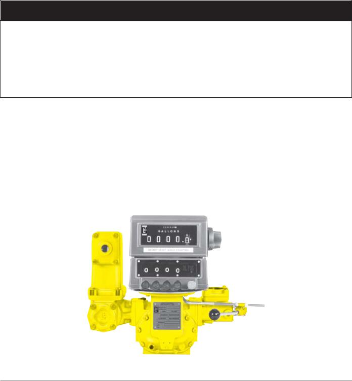
The LectroCount LCR is an electronic meter register that can be used to calibrate a flow meter, control a security valve, output delivery information via an LCD display and printer, and, optionally, perform electronic temperature volume compensation. The LCR receives its flow input signal from either an external pulser, a meter output, or an internally mounted quadrature pulser that is mechanically connected to the flow meter. LCR is housed in a weather and explosion proof enclosure that can be mounted directly atop many common positive displacement meters. Alternatively, the LCR may be mounted remotely from meters utilizing external pulsers. A backlit remote electronic counter with a six digit display on top of the LCR housing provides a real time readout of product delivered.
Operation
The LCR can be operated as a stand-alone system, as a stand-alone system with electronic presetting, and as a slave to a host controller such as a hand held computer, process controller, or vehicle mounted data terminal. It can be used in mobile and fixed installations. When installed with the proper system accessories the LCR can be used for Weights & Measures approved custody transfer transactions.
Outputs
Information from the LCR can be output via an RS-232 printer port, RS-485 or RS-232 communication port, a scaled pulse output,and a counter output.
Installation
This manual describes the installation and operation of the LCR and its optional accessories. Read this entire manual before beginning the installation to make sure that you understand the total scope of the project. Specific installation requirements will vary with the model of truck, the physical layout of a fixed installation, the configuration of any existing metering equipment, the options that are selected, and the type of fluid being metered. Make sure that the LCR, and accessories such as the Electronic Temperature Volume Compensation kit and the control valves can be installed in such a manner so as to not interfere with routine service of the meter and strainer. The conduit and wiring for the above components need to be routed with similar concerns in mind.
This manual applies to LCR’s equipped with SR 200 Series software.
3

Installation Overview
Meters with LCR (factory installed)
In many instances, the LCR will be factory installed on a Liquid Controls meter, along with a strainer/air eliminator and security valve. In such cases, the user may proceed to page 10 of this manual “Wiring the LCR” after verifying that the truck electrical system meets the specifications listed below.
Field retrofit of LCR to existing meters
For field installation of the LCR to a meter the steps listed below, and described in this manual, should be followed. A typical truck installation includes the following steps:
•Ensure that the truck electrical system meets specifications
•Remove existing mechanical registration equipment
•Remove manual preset valve
•Install an electronically controlled security/preset valve
•Mount LCR to the meter
•Install optional peripheral accessories including electronic temperature/volume
compensation (ETVC) kit, odometer pulser, remote START/STOP switch, etc…
•Route factory supplied cables from LCR to truck cab
•Mount printer in cab
•Connect printer and LCR to truck’s accessory circuit (12 VDC)
Electrical check for Truck Installations
Before beginning the installation, make sure that the truck electrical system meets the minimum requirements to correctly power the LCR. The truck system should produce at least 12.6 VDC to reliably power the LCR and the valve control solenoids. Truck systems that do not meet this requirement need to be serviced to ensure that the LCR will be reliably powered. The LCR computer will power down if the voltage drops below 9 VDC.
The truck system must meet the following requirements:
•Make sure that, with the truck running at low idle and ALL accessories on (including the hose reel), the voltage does not drop below 9 volts.
•Be sure that all radio antennas have been installed in accordance with the manufacturer’s specifications to prevent RF interference.
NOTE: The LCR power cable kit includes a fuse holder and a 5 Amp fuse to protect the truck system in the event of a short circuit in the cable. Liquid Controls recommends that this fuse be used in all installations not having a fused accessory block to protect the truck in the event of cable faults. A 5 Amp fuse is required.
4

Specifications
Power Requirements
+9 to 28 Volts DC @ less than 3 Amps for entire register including solenoid valves. The system can operate with either a positive or negative ground.
Pulse Input
5 to 28 volt peak to peak square wave from an open collector with pull-up resistor greater than 750 ohms. Quadrature or single channel with a direction logic line. Frequency not to exceed 2500 Hz.
Scaled Pulse Output
The scaled pulse output reflects net volume if temperature compensation is being employed or gross volume if temperature compensation is NOT employed. One pulse will be output per least significant digit of the display, i.e., a system set to read in 1/10 gallon will provide one pulse per 1/10 gallon (10 pulses per gallon).
Open drain output common to the negative power input line. Sinking capability up to 150 mA. Maximum open circuit voltage is 28 VDC.
Auxiliary Outputs
This output can be used to add features such as pump control or additive injection.
Aux 1: Open drain output common to the negative power input line. Sinking capability up to 1 Amp. Maximum circuit voltage is 28 VDC.
Aux 2: Open drain output common to the negative power input line. Sinking capability up to 150 ma. Maximum open circuit voltage is 28 VDC.
Solenoid Outputs
Open drain transistor common to the negative power input line. Sinking capability up to 1 Amp. Maximum open circuit voltage is 28 VDC.
Up/Down/Reset pulse to Remote electronic counter
Open drain transistor capable of sinking 1 Amp. Maximum open circuit voltage is 28 VDC.
Pulses are active low and are approximately 10 μsec in duration. The LCD counter is reset by turning on both outputs for 0.01 second.
RS-232 I/O Port
Meets EIA -232E standard but only incorporates four signaling lines:
•Transmit data
•Receive data
•Request to Send or Data Set Ready
•Clear to Send or Data Terminal Ready
The printer output port is compatible with the Epson TM TM 290 II, TM 295, TM 300, TMU 200D, TMU 295 printers, Axiohm Blaster, and Okidata™ ML184 printer.
RS-485 I/O Port
Line terminations are SAE J1708 standard compatible which allows up to 20 units per network.
RTD
Four-wire platinum sensor with 100 ohms resistance at 0°C and 138.5 ohms resistance at 100°C.
Accuracy per IEC 751 Class B.
Printer (Epson Model 295)
Operating temperature: -22° to 104°F (-30° to 40°C). Printer must use multi-part NCR forms and operate without a ribbon (impact image on form) to operate in the low end of the temperature range.
5

Regulatory Specifications
Weights & Measures - Custody Transfer
United States |
NTEP Certificate of Conformance #86-022. Complies with requirements in NIST handbooks |
|
44 and NCWM Publication 24 for use with any approved meter. |
Canada |
Measurements Canada Notice of Approval #AV-2342. Complies with Weights & Measures |
|
Acts, Regulations, Specifications, Bulletins, and Rulings/Interpretations including specifica- |
|
tions SVM-1 and SVM-2 for use with any approved meter. |
International |
OIML R117 Report through Nederlands Meetinstituut (NHMi) |
|
|
Safety Approvals
United States/ |
Class I, Division 2, Groups C & D (non-incendive), IP66 |
Canada |
Class I, Division 2, Groups C & D (non-incendive), IP66 |
|
|
EMC
United States |
Cispr A |
Canada |
SVM 1 |
International |
ISO 7637, EN 50081-1, EN 50081-2, EN 50082-1, and EN50082-2. Also complies with OIML |
|
R117 for Class I |
|
(Mobile instruments, in particular measuring systems on trucks). Self-declared CE Mark. |
|
|
Mechanical/Climatic Suitability
Ratings |
Operating Temperature: -40° to 158°F (-40° to 70°C) |
|
Relative Humidity: 0 to 100% |
IP 66 |
Dust tight, dust will not enter. |
|
Protection against a powerful jet of water from all practical directions. |
NEMA 4X |
Either indoor or outdoor use to provide against falling rain, splashing water, and hose-directed |
|
water; undamaged by the formation of ice on the enclosure; resists corrosion. Plastic lens is |
|
resistance to UV and water immersion. Gaskets are resistant to aging. |
OIML R117 |
Includes testing for Dry Heat, Cold, Damp Heat Cyclic, and Vibration (sinusoidal) |
|
|
! IMPORTANT
For North American Installations, the installation must be fully in accordance with the National Electrical Code (US) or the Canadian Electrical Code respectively to maintain the hazaardous location ratings on the product. This may involve using rigid conduit for all connections.
For European installations, the installation must be fully in accordance with EN60079-14 to maintain the hazardous location ratings on the product. This may involve using special cable gands for all connections.
6
|
|
Parts Requirements |
Liquid Controls Supplied Components |
Installer Supplied Parts |
|
LCR register, and LC-supplied options including; printer, |
• |
All conduit/cable glands |
Lap Pad, control valve or solenoid, ETVC kit, glandless |
• |
All fittings |
pulse output device (POD), odometer kit, preset switch, |
• |
Hardware for printer mounting brackets |
remote START/STOP switch, communication protocol |
• |
Non-standard cables or cable extensions |
selector switch (RS232/485), power cable, and printer/ |
|
|
Lap Pad cable. |
|
|
! WARNING
Before disassembly of any meter or accessory component, ALL INTERNAL PRESSURES MUST BE RELIEVED AND ALL LIQUID DRAINED FROM THE SYSTEM IN ACCORDANCE WITH ALL APPLICABLE PROCEDURES. Pressure must be 0 (zero) psi. Close all liquid and vapor lines between the meter and liquid or gas pressure source.
For Safety Rules regarding LPG, refer to NFPA Pamphlet 58 and local authorities.
Failure to follow this warning could result in property damage, personal injury, or death from fire and/or explosion, or other hazards that may be associated with this type of product.
Removing Existing Mechanical Registration Equipment
Liquid Controls Meters
Remove the mechanical register components by removing the four bolts that attach the register “stack” to the meter. (See illustration below).
Neptune Fuel Oil Meters
Remove the mechanical register from the meter, leaving just the star shaped gear and two square headed studs.
Neptune LPG Meters with Mechanical TVC’s
Remove the mechanical register and the mechanical automatic temperature compensator from the meter leaving just the star shaped gear.
Removing mechanical register stack from Liquid Controls meter (typical).
7
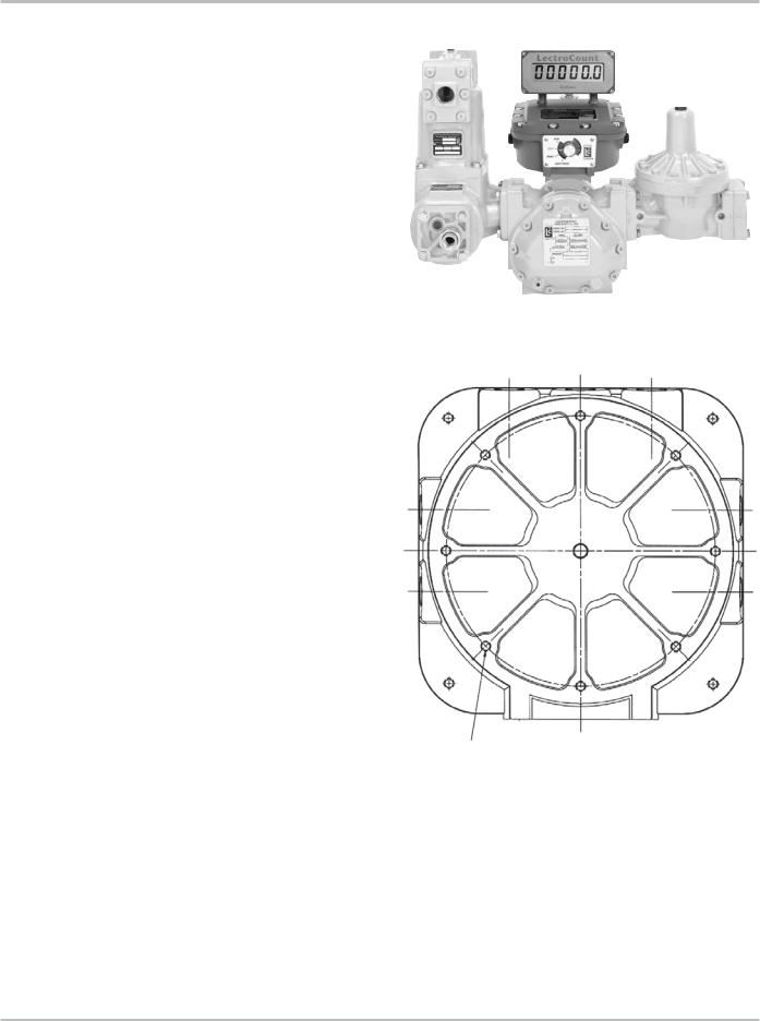
LCR Register Mounting
The LCR register is usually mounted on the liquid flow meter, though for fixed installations it can be mounted up to 1000 wire feet (304.0 meters) away from the meter if the meter is equipped with an external pulser. The actual distance depends on the pulser specifications and the type of wire used to install it. Contact the factory if your installation requires pulser or RTD cable lengths greater than 1000 feet.
LCR Mounting Bolt Pattern
The LCR base casting contains eight mounting holes in an industry standard bolt pattern that allows it to be easily attached to a number of common meters. All of the holes are 1/2” deep and will require 1/4 - 20” screws.
Refer to the drawing below if you will need to fabricate a mounting bracket for the LCR. Brackets and adapters are available from Liquid Controls for many common meters. Installation instructions are packed with the mounting or adapter kit. When mounting the LCR, leave the cover assembly fastened to the base to protect the internal components. As the LCR is placed on top of the meter, make sure the vertical drive shaft from the meter is attached to the pulser drive shaft using the kit provided. Before securely fastening the LCR to the meter or bracket, make sure that the counter is visible and that the selector switch can be easily operated.
NOTE: If the LCR will be exposed to the elements before the installation is complete, make sure that the cover gasket is in place and that all (12) M8 mounting bolts and washers are snugly installed. Also, remove all of the pipe plugs from the LCR’s seven 1/2” NPT conduit hubs, apply pipe sealant or Teflon tape to the threads, then re-install the plugs in the ports.
NOTE: When removing/installing cover screws, switch plate screws, or display cover screws, apply antiseize compound to the screws upon reassembly to ensure easy removal at later date.
Mounting Holes:
.250-20 UNC -2B .50 Deep
8 Holes Equally Spaced on a 6.65 Dia. Circle.
8
 Loading...