

Page 1
STAGESCAPE M20d
Advanced Guide
Rev A © 2012 Line 6, Inc.
Page 2

Table of Contents
M20d Overview ...................................................................... 1•1
Hardware Legend ........................................................................................... 1•2
Main Toolbar .................................................................................................. 1•5
Stage Icon Gallery .......................................................................................... 1•6
Controller Strips ............................................................................................ 1•7
Contextual Browsers ...................................................................................... 1•8
Hardware Encoders ........................................................................................ 1•9
Setup Mode ............................................................................ 2•1
Creating Input Channels ............................................................................... 2•1
I/O Panel ........................................................................................................ 2•4
Customizing Stage Icons ................................................................................ 2•5
Auto Trim ....................................................................................................... 2•6
Saving & Loading Setups ............................................................................... 2•8
Group Encoders .............................................................................................. 2•7
Channel Presets Overview ............................................................................. 2•9
Tweak Mode ............................................................................ 3•1
Quick Tweak .................................................................................................. 3•2
Deep Tweak .................................................................................................... 3•9
Input Settings ............................................................................................... 3•11
Monitor Settings .......................................................................................... 3•12
Global FX Settings ....................................................................................... 3•14
Media Player ................................................................................................. 3•16
Record Mode .......................................................................... 4•1
Quick Capture ................................................................................................ 4•1
Recording ....................................................................................................... 4•2
Page 3

Monitor Mode ......................................................................... 5•1
Channel Monitor Levels ................................................................................ 5•2
FX Monitor Levels ......................................................................................... 5•4
Perform Mode ........................................................................ 6•1
Saving & Loading Scenes .............................................................................. 6•1
Encoder Assignments ..................................................................................... 6•2
Mute & Solo .................................................................................................. 6•3
Footswitches ........................................................................... 7•1
Footswitch View ............................................................................................. 7•1
Assignment Options ..................................................................................... 7•3
Managing L6 LINK Devices ................................................... 8•1
Auto-assign L6 LINK Speakers ...................................................................... 8•2
Speaker Controls ............................................................................................ 8•6
System Settings ..................................................................... 9•1
Wi-Fi Remote Setup ...................................................................................... 9•2
Backup & Restore .......................................................................................... 9•6
Firmware Updates .......................................................................................... 9•7
Setup Examples ................................................................... 10•1
Duo With Backing Tracks ............................................................................ 10•1
Rock Band ................................................................................................... 10•6
Electronic Artist ......................................................................................... 10•10
Setup Tips ................................................................................................... 10•16
Appendix A: Channel Processing ......................................... A•1
Appendix B: Global FX ..........................................................B•1
Appendix C: Preset DSP Types ............................................ C•1
Page 4

Page 5

M20d Overview
M20d Overview
Welcome to the StageScape™ M20d Advanced Guide.
StageScape M20d is the world’s first smart mixing system for live sound. Utilizing a
groundbreaking touchscreen visual mixing environment, StageScape M20d streamlines
the way you mix to get your sound dialed in quickly and stay in the creative zone.
This M20d Advanced Guide contains in-depth details of your M20d’s features and
functionality, and includes comprehensive information on the following:
• Setup Mode, Tweak Mode, Record Mode, Monitor Mode, Perform Mode
• Assigning Footswitches
• Managing L6 LINK Devices
• System Settings
• Setup Examples
• Channel Processing
• Global FX
• Preset DSP Types
Before You Begin
Check your M20d’s System Version to make sure your M20d is running the latest
firmware. To do so, tap the Info button in the Main Toolbar, upper right, then select
Show System Settings. The About page will be displayed by default, with your System
Version listed at the top of the page.
1•1
You can download the latest M20d firmware at http://line6.com/software. You can also
find various M20d resources at http://line6.com/stagescape-m20d/resources, including a
Quick Start Guide, M20d Specifications pdf and an interactive Quick Start Tutorial.
For onboard Help, tap the M20d’s Info button and select View Help. Then select any of
the available Help Topics for extensive detailed infomation.
Page 6
M20d Overview
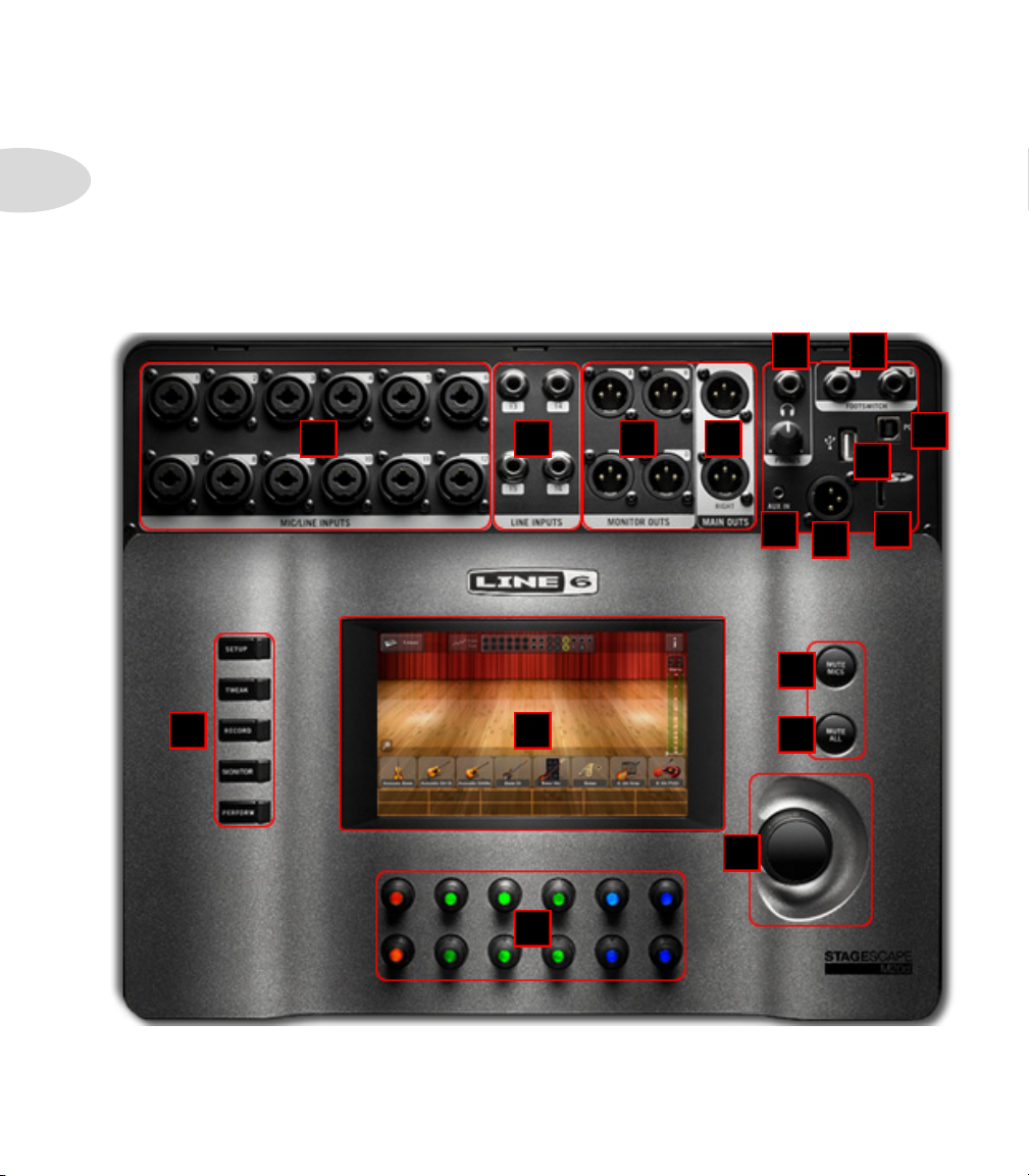
Hardware Legend
Below is an overview of the M20d hardware, with descriptions of inputs, outputs and user
1•2
interface elements listed on Page 3. As you can see, all input and output connections are
easily accessible on the front panel.
The primary user interface is software-based, displayed in color on the 8.6” touchscreen.
We’ll describe the M20d’s user interface in more detail throughout this guide. To get
started, please review the hardware legend.
E F
BA C D
L M
Q
P
G
H
I
K
J
N
O
StageScape M20d
Page 7
A
Mic/Line Combi Inputs - Twelve mic or line level inputs (XLR or 1/4 inch).
B
Line Inputs - Four 1/4 inch line level inputs.
C
Monitor Outputs - Four XLR outputs for stage monitors.
D
Main Outputs - Stereo XLR outputs of the Main Mix.
E
Headphones Output - Stereo headphones out with volume control.
F
Footswitch Jacks - Jacks for footswitches 1 & 2.
G
USB Out To PC - USB output to computer.
H
USB Media Port - USB port for thumb drive or hard disk media.
I
Aux Input - Stereo 1/8 inch jack for auxiliary audio input.
J
L6 LINK Output - XLR output to other L6 LINK devices.
M20d Overview
1•3
K
SD Card Input - Card slot for SD media.
L
Mode Buttons - Mode buttons for Setup, Tweak, Record, Monitor & Perform.
M
Touchscreen Display - Interactive touchscreen user interface.
N
Mute Mics Button - Toggles the mute state of input channels.
O
Mute All Button - Mutes the mains and monitor outputs.
P
Master Level Encoder - Adjusts the level to the main stereo outputs.
Q
Rotary Encoders - Provide control over matching on-screen Controller Strips.
Page 8
M20d Overview
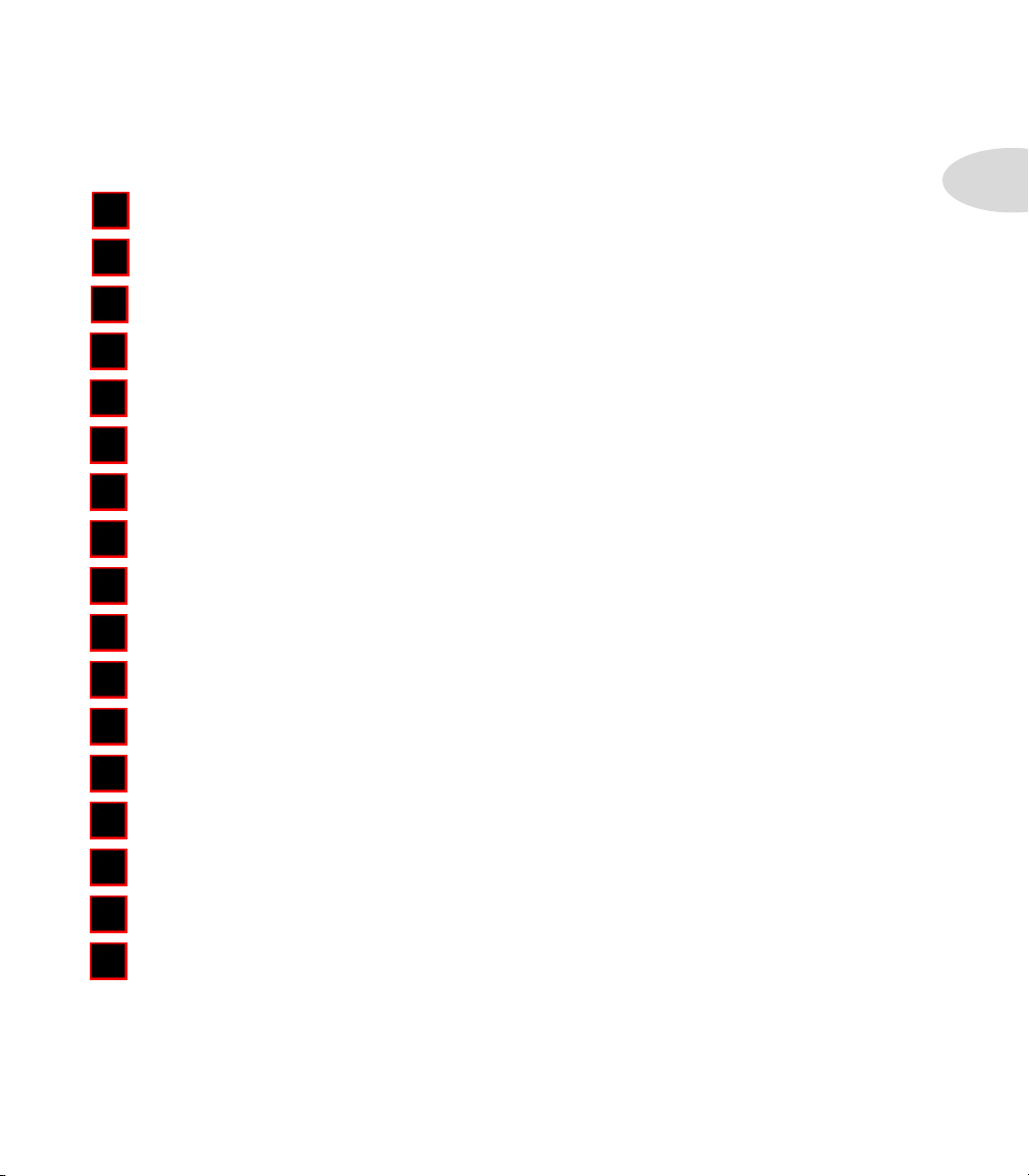
Main Toolbar
The Main Toolbar is located at the top of the M20d’s touchscreen. It displays various
1•4
visual elements and buttons depending on the M20d’s current mode, which is determined
by whichever hardware Mode Button is enaged, as described on Page 3, item L. Below
are illustrations of the various states of the Main Toolbar according to the currently
selected M20d mode. More detail will be provided in subsequent chapters.
Setup Mode
In Setup Mode, the Main Toolbar includes the I/O Panel and buttons for Setups,
Encoder Assign, Auto Trim, Info and Edit Properties (when a Stage Icon is selected).
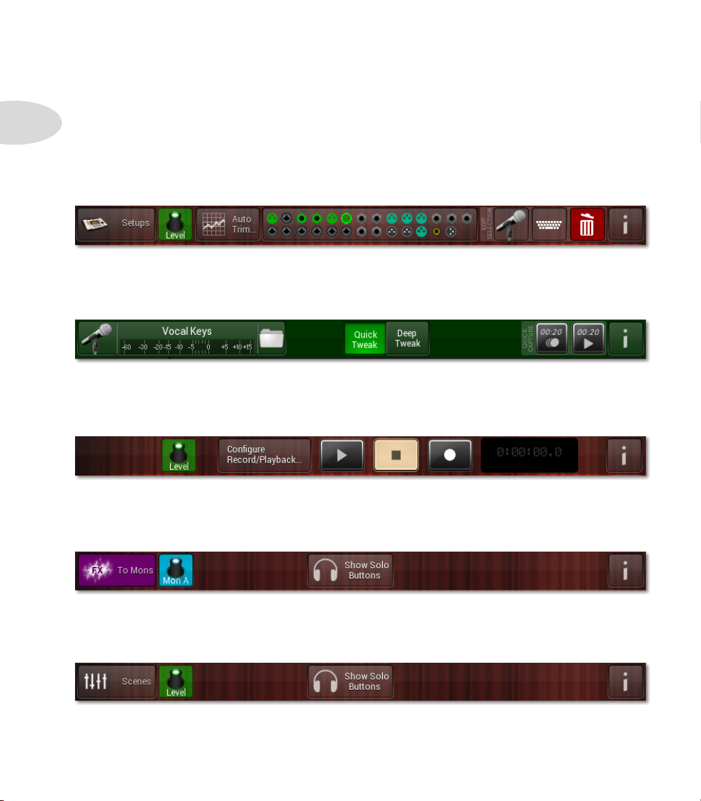
Tweak Mode
In Tweak Mode, the Main Toolbar includes a channel level meter, Load Presets
folder, and buttons for Quick Tweak, Deep Tweak, Info and Quick Capture.
Record Mode
In Record Mode, the Main Toolbar includes Recording Transport controls and
buttons for Encoder Assign, Info and the Record/Play Counter.
Monitor Mode
In Monitor Mode, the Main Toolbar includes buttons for FX To Monitors, Encoder
Assign, Show Solo Buttons and Info.
Perform Mode
In Perform Mode, the Main Toolbar includes buttons for Scenes, Encoder Assign,
Show Solo Buttons and Info.
Page 9
Stage Icon Gallery
The Stage Icon Gallery, visible in Setup Mode, is the horizontal strip of gear icons
at the base of the stage. It includes a collection of commonly used gear items, which in
addition to providing a useful visual correlation to your onstage gear, establishes powerful
audio signal processing settings for each preset, to ensure each channel will sound as good
as if it were mixed by a professional live sound engineer.
Swipe the Stage Icon Gallery to the left or right to see more Stage Icons. At the far
right you’ll see a More folder icon, which provides access to the complete Preset Library.
See the Setup Mode chapter for more details on the Stage Icon Gallery and Channel
Presets, including customizing Presets and building your stage view.
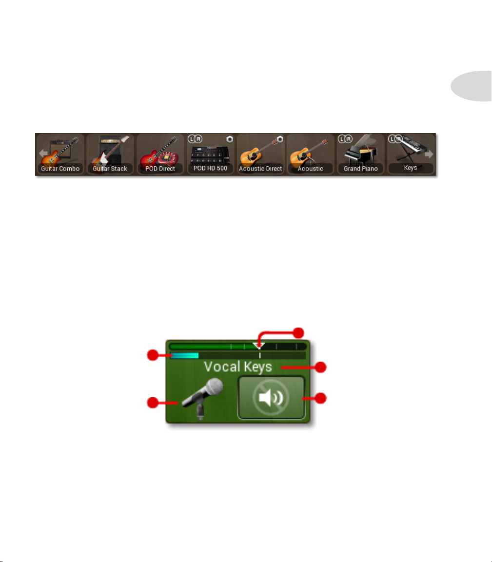
Controller Strips
The Controller Strips are located at the base of the stage. They display indivual channel
information such as Channel Name, Channel Icon, Fader Level, Output Level and Mute
or Solo state, as illustrated below in Perform Mode or Record Mode.
M20d Overview
1•5
Level Fader
Channel Output Meter
Channel Name
Channel Icon
In Monitor Mode the Controller Strips are blue, and the Mute button is replaced by a
Linked/Unlinked button. See the Monitor Mode chapter for more details.
In Setup Mode the Controller Strips are half height and display only Channel Name,
Fader Level and Output Level. Each controller strip is matched to a color-coded M20d
hardware encoder, which controls either channel level or monitor level.
Mute Button
Page 10
M20d Overview
Contextual Browsers
When various buttons are tapped in the M20d user interface, contextual windows may be
1•6
displayed on the screen. For example, when a Stage Icon is selected in Setup Mode, the
Edit Properties buttons will slide into view on the Main Toolbar.
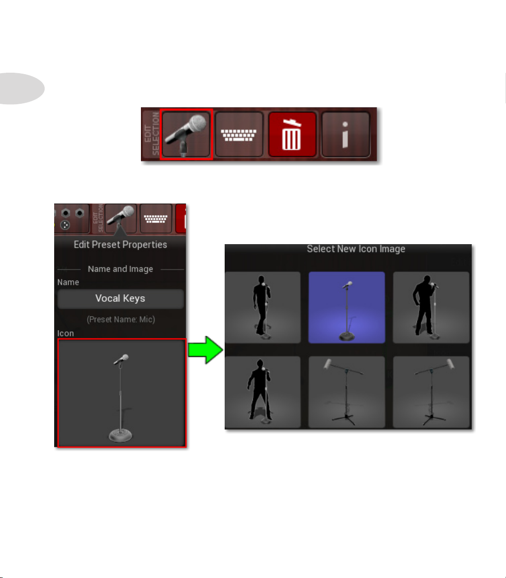
If you then tap the Channel Icon button, the Edit Preset Properties window will be
displayed, where you can browse various icons to replace the current one.
You can also rename the channel from this window by tapping the Name field, causing an
onscreen text keyboard to appear.
Similar contextual windows will be displayed for Setups and Auto Trim in Setup Mode,
Scenes in Perform Mode, Configure Record/Playback in Record Mode, Edit Preset
Properties and Load/Save Presets in Tweak Mode, among others.
Page 11
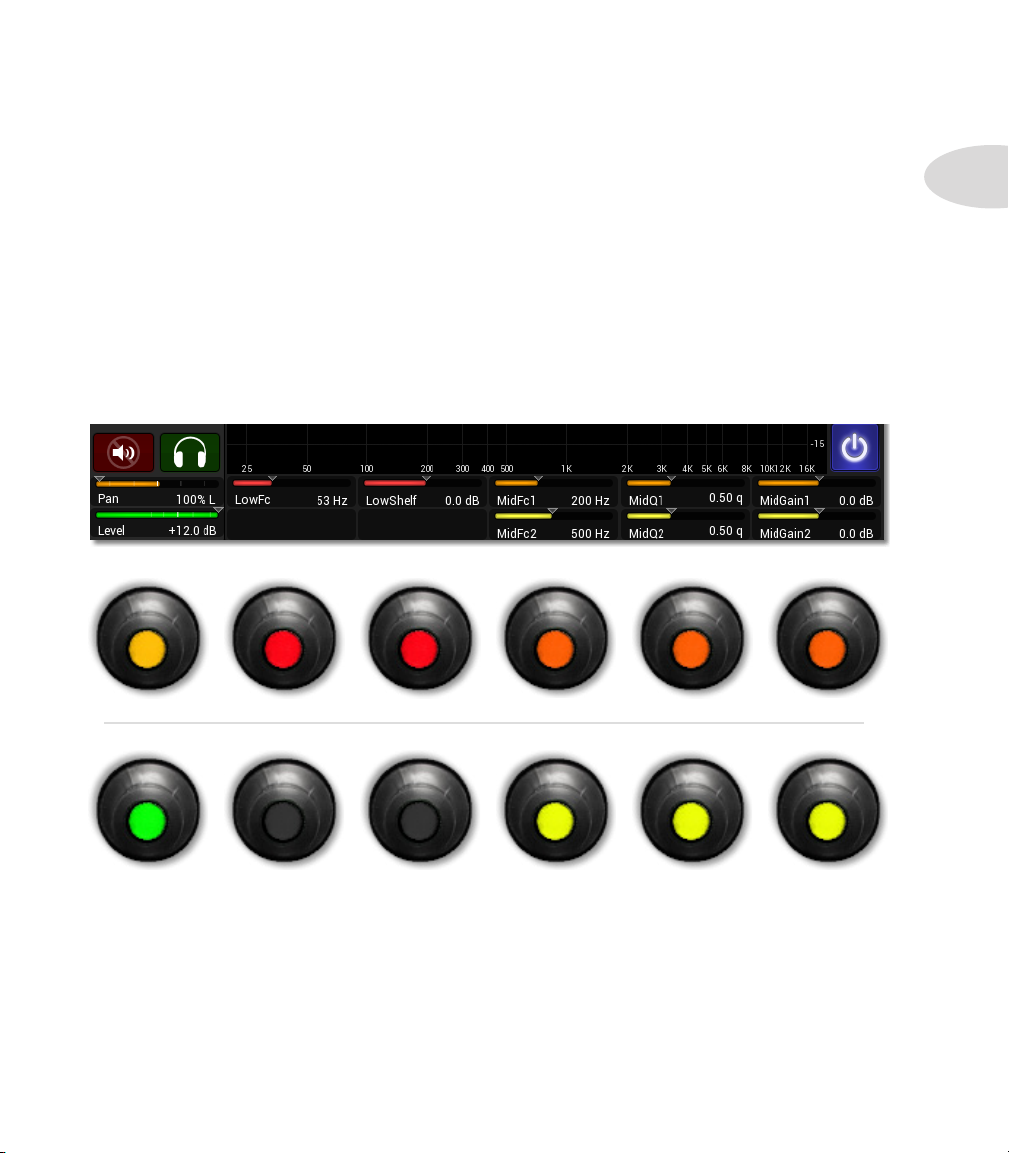
Hardware Encoders
The 12 Hardware Encoders make it easy to adjust various software parameters displayed
on the M20d touchscreen. They are color-coded in each case, and are matched up with
specific parameters depending on the current view and encoder assignment.
For example, in Setup and Perform mode they can control Channel Level, Trim, Pan
or FX Send. In Deep Tweak mode, encoders #1 and #7 control Pan and Level, and if
an EQ processor is selected, for example, several other encoders light up and control EQ
Frequency, Q, Gain, etc.
To illustrate, below is a graphic of the 12 encoders as they would be assigned to the EQ6
processor in Deep Tweak mode, lit up in various colors to match their EQ6 parameter
assignments.
M20d Overview
1•7
Pan
100%L ~ 100%R 20Hz ~ 500Hz -15dB ~ +15dB 20Hz ~ 18kHz 0.1q ~ 10.0q -15dB ~ +15dB
Level
Off ~ +12dB 20Hz ~ 18kHz 0.1q ~ 10.0q -15dB ~ +15dB
Low Freq Low Shelf Mid Freq 1
Mid Freq 2
Mid Q 1
Mid Q 2
Mid Gain 1
Mid Gain 2
Observe how encoder #2 is red to match up with Low Frequency, encoder #7 is green to
match up with Level, and encoder #10 is yellow to match up with Mid Frequency 2. When
anencoderisnotassigned,itwillnotlightupatall,aswithencoders#8and#9.
As you switch M20d modes, you’ll see the encoders changing color in sync with the
touchscreen, making for intuitive control of the various parameters in the UI.
Page 12

Page 13
Setup Mode
Setup MOde
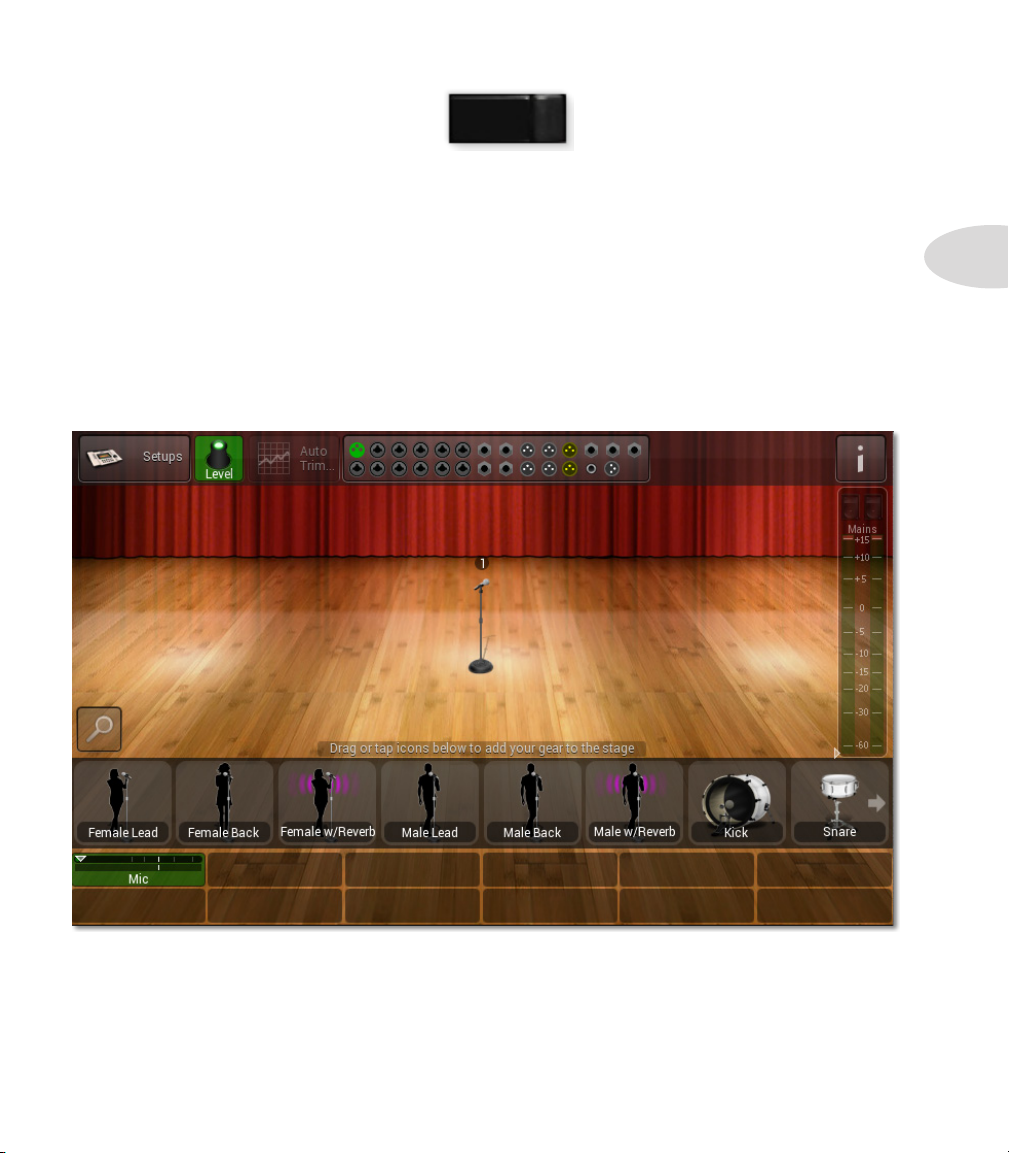
When you first power up your StageScape M20d, you will need to set up your inputs,
outputs and channel assignments in Setup Mode.
The M20d will power up in Setup Mode, or you can enter Setup Mode at any time by
pressing the hardware SETUP button. The touchscreen will display the Stage View, the
Stage Icon Gallery, the Controller Strips, and the Main Toolbar, which includes the
Setups button, Encoder Assign button, Auto Trim button, I/O Panel and Info button.
Below is an illustration of the M20d touchscreen in Setup Mode, with one XLR
microphone connected to Input #1.
SETUP
2•1
Creating Input Channels
There are 3 main ways to create Input Channels and configure your outputs and channel
assignments: Physical Connections, the Stage Icon Gallery and Setups.
Page 14
Setup Mode
Using Physical Connections
2•2
Plug in the various cables to connect your mic and line inputs, mains and monitor speakers.
The M20d will sense an XLR or 1/4 inch jack has been plugged in, and a graphic connector
will be displayed on the I/O Panel for each jack, indicating a valid connection.
A default Stage Icon will appear on the stage for each connected input, and a Controller
Strip will automatically be assigned to it. When all your gear has been plugged in, the
stage will be populated with various default stage icons associated with the physical gear
you have connected.
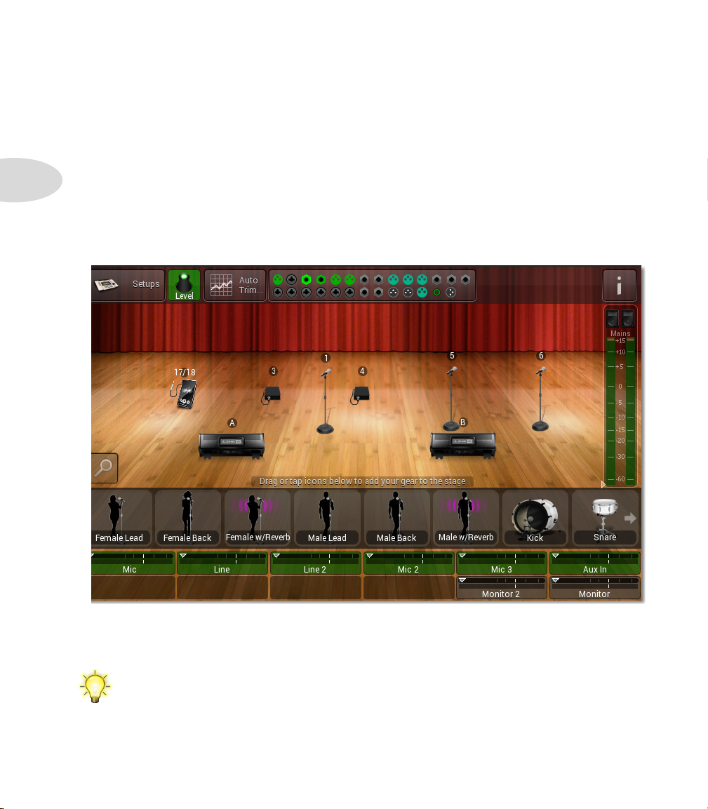
Below is an illustration of a Duo setup with 2 mics, a PC, line inputs, monitors and mains.
The next step when connecting your gear in this way would be to customize your stage
icons and channel presets to match your physical gear.
See Chapter 10: Setup Examples for more details on setting up your gear using
physical connections, using the above Duo setup as an example.
Page 15
Using The Stage Icon Gallery
Instead of plugging in your gear first, you can create various input channels using the Stage
Icon Gallery, which is the horizontal strip of icons displayed just above the controller
strips. Swipe the gallery left or right to reveal all the icons, including the More folder.
See the Channel Presets section on Page 2•12 for more detail on Preset customization.
Setup Mode
For each input channel you’d like to create, tap or drag an icon from the Stage Icon
Gallery, or tap an icon to replace a selected icon image. The stage icon will be placed on
the stage, and a controller strip will automatically be assigned to it. The channel will be
loaded with a default Channel Preset, and if there is no physical input connection yet for
the selected icon, the associated input graphic on the I/O Panel will be colored dim amber.
2•3
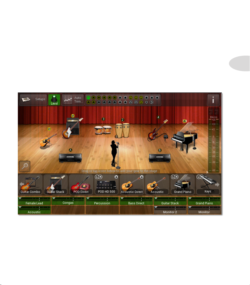
Above is an example of a stage setup created entirely by using the Stage Icon Gallery, with
only one XLR cable plugged in for the Female Vocal in channel #1. Inputs 2 through 8 on
the I/O Panel are colored dim amber, as are the monitor and mains jacks.
The next step when configuring your setup in this way would be to plug in the various
cables to connect your gear as depicted on the M20d stage, at which time their I/O Panel
connectors will be colored green.
Page 16
Setup Mode
Using Setups
The third way to set up your M20d inputs, outputs and channel assignments is to load a
Setup. A Setup is defined as the current configuration of all M20d inputs and outputs, all
FX and channel settings, levels, mutes, pans, monitor levels, footswitch assignments, L6
LINK settings and your stage icon layout.
2•4
The most recent Setup is persistent in M20d internal memory, and it will automatically be
loaded at power up. So if you’ve previously configured your M20d, your Setup at power up
will be exactly as you left it during your last session. And if you’ve previously saved one or
more Setups, you can recall and load any one of them by tapping the Setups button in the
Main Toolbar. (See Page 2•9 for more details on saving and loading Setups).
All I/O Panel graphic jacks in the Setup will be assigned as you last saved them, and will
be displayed as either amber (if not yet connected) or green (if connected). Your previous
stage icons and channel names will also be retained.
I/O Panel
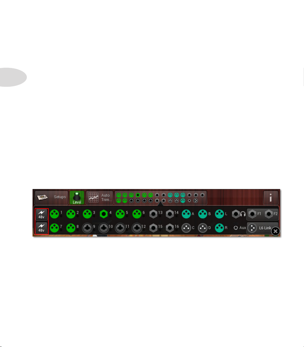
The I/O Panel in Setup Mode is essentially a mirror image of the physical M20d’s I/O
Panel. It displays all your input and output connections and enables you to swap them
around, if needed, via the touchscreen UI. To zoom in on the I/O Panel just tap it in the
Main Toolbar. This gives you access to the +48V buttons.
+48 V Buttons
When using condenser microphones, you may need +48V power. The M20d provides this
via the +48V power buttons when you zoom in on the I/O Panel. The top +48V button
powers the top row of Mic inputs, and the bottom +48V button powers the bottom row.
I/O Reassignment
On occassion you may find that you need to reassign an instrument to a different input, or
a stage monitor to a different output. Suppose you have ideal channel settings for Input 1
prior to connecting any microphones or instruments to the M20d, and it happens that the
instrument intended for Input 1 has been connected to Input 4. You may be inclined to
Page 17
Setup Mode
swap the physical connections of inputs 1 and 4, but that may prove to be impractical in a
critical live performance scenario.
In a situation like this the M20d provides I/O Reassignment, using the touchscreen UI.
This feature is also accessible remotely using the free StageScape Remote app for iPad®.
To reassign jacks in Setup Mode using the virtual I/O Panel, follow these steps:
1. Select the Stage Icon for the input assignment you wish to reassign.
2. Tap the I/O Panel in the Main Toolbar to zoom in on it.
3. The selected Stage Icon’s current input jack will be highlighted.
4. Tap the input jack to which you wish to assign the selected Stage Icon.
5. The selected Stage Icon’s input jack is now the jack you tapped in Step 4.
Note: only presets with the 1/4” badge can be swapped or assigned to Inputs 13-16.
Tip : If you tap an input jack to which another channel is already assigned, the
inputs of that channel and the currently selected channel will be swapped.
Tip : You can also reassign outputs for Monitors A-D using this operation.
Customizing Stage Icons
When you’d like to change the appearance of a stage icon and retain its channel settings,
this is easily accomplished by using the Edit Selection button in the Main Toolbar.
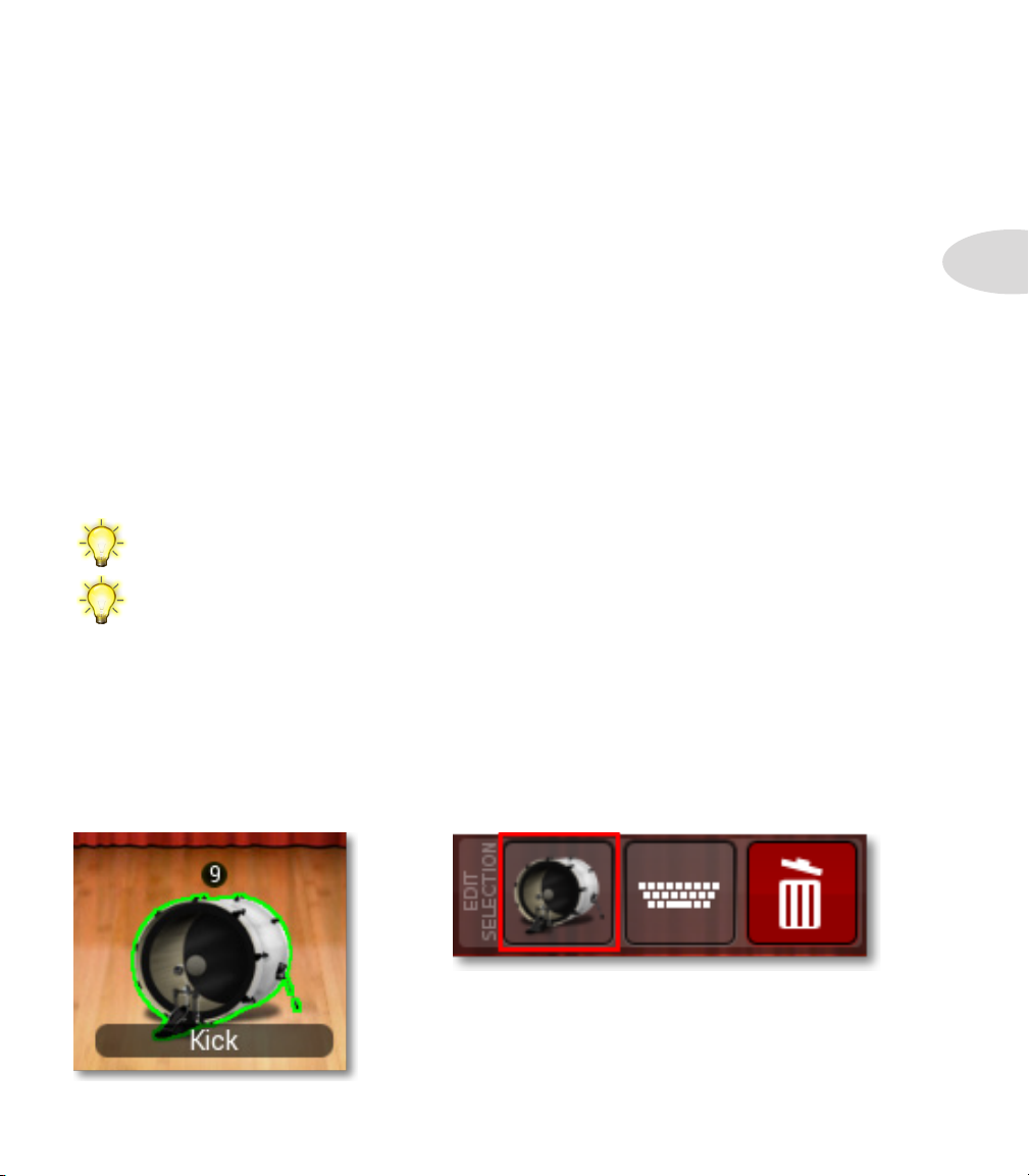
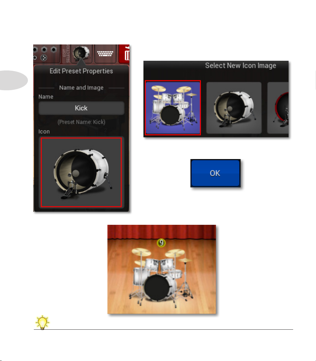
For example, let’s say you have a Kick drum stage icon and you’d like it to represent a full
drum set. First tap the Kick stage icon to select it.
2•5
Then tap the Edit Selection Icon in the Main Toolbar.
Page 18
Setup Mode
2•6
The Edit Preset Properties window will open. Tap the Kick Icon image to select it.
The Select New Icon Image browser will open.
Select the Drums category, then tap the Drum Set icon.
Tap the blue OK button. This replaces the Kick icon
with the Drum Set icon, which will now be displayed on
the stage.
For more details on customizing Stage Icons, see Chapter 10: Setup Examples.
Page 19
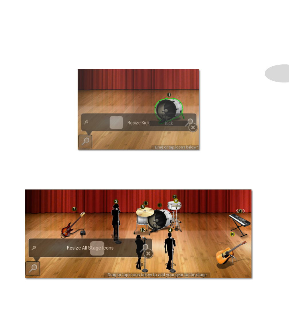
Resizing Stage Icons
If you find that you have quite a few stage icons on your stage, you may want to make them
a little smaller. Or if you have a low channel count, you may want to make them a little
larger. With the Resize Slider, it’s easy to resize your stage icons, as follows:
To resize a single Stage Icon:
1. In Setup Mode, select the Stage Icon you wish to resize.
2. Press the Resize button in the bottom-left of the Stage View.
3. Drag the popup Resize Slider left or right to decrease or increase the icon’s size.
Setup Mode
2•7
To resize all Stage Icons simultaneously:
1. In Setup Mode, select the Stage View background so that no Stage Icon is selected.
2. Press the Resize button in the bottom-left of the Stage View.
3. Drag the popup Resize Slider left or right to decrease or increase the icon’s size.
Page 20
Setup Mode
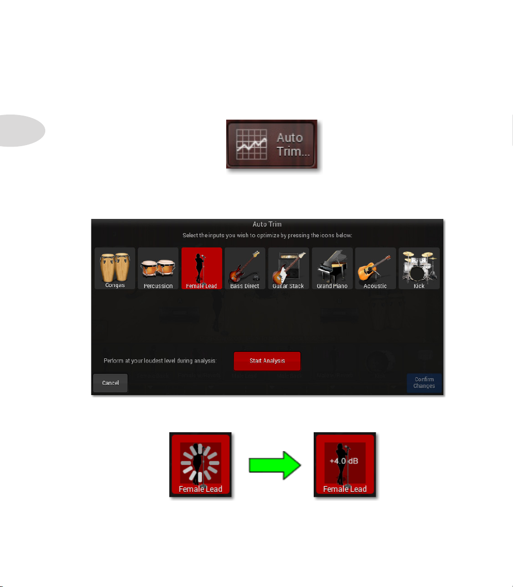
Auto Trim
2•8
The Auto Trim feature optimizes a channel’s input level by quickly analyzing it, then
setting the new trim level automatically. This ensures that you always have the best
possible input level while guarding against channel distortion. To use Auto Trim, tap the
Auto Trim button in the Main Toolbar.
The Auto Trim window will open. Tap the icon of the channel you’d like to optimize - in
this example, Female Lead is selected. Tap the Start Analysis button while performing
at your loudest level.
Auto Trim will analyze the input level, displaying an activity graphic over the channel
icon. After a few seconds, any needed trim adjustment will be displayed in dB.
Auto Trim will analyze the input level and display an activity graphic over the channel
icon. After a few seconds, any needed trim adjustment will be displayed in dB. To apply
the new optimized trim level to the channel, tap the blue Confirm Changes button.
Page 21
Saving & Loading Setups
A Setup is analogous to the collection of gear you would bring to a live show, as well as
the M20d channel information. This may include vocal mics, guitars, a bass rig, drum kit,
digital keyboard and perhaps an MP3 player or laptop computer. Additionally, you may be
responsible for providing your own stage monitors and front of house speakers.
Setup Mode
An M20d Setup, as mentioned on Page 2•6, is defined as the current configuration of
all your inputs and outputs, FX and channel settings, levels, mutes, pans, monitor levels,
footswitch assignments, L6 LINK settings and your stage icon layout, which represents
your onstage gear.
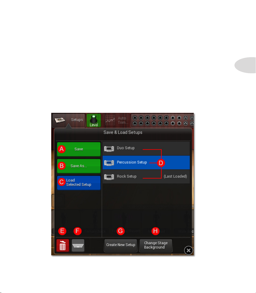
To save, load, rename, delete or create a new Setup, tap the Setups button in the Main
Toolbar. The Save & Load Setups window will open, as illustrated below.
2•9
The following page describes the Setup functions that can be performed from this window.
Page 22
Setup Mode
2•10
Save & Load Setups Functions
A. Save the current Setup. Tap this button to save the current configuration. Since “Rock
Setup” is the last loaded Setup, any changes made will be saved to “Rock Setup”.
B. Save the current configuration as a new Setup. Tap this button and the text keyboard
window will open. You can then name the current Setup and save it.
C. Load the selected Setup. In this example, the “Percussion Setup” is selected in the
Setups list (D), so “Percussion Setup” would be loaded when tapping this button.
D. This is the Setups List. It includes all the Setups you currently have saved in the
M20d’s internal memory.
E. Delete the selected Setup. When you tap the Delete button, a confirmation dialog will
be displayed to confirm deleting the currently selected Setup in the Setups list (D).
F. Rename the selected Setup. Tap the Rename button and the text keyboard window will
open. You can then rename the currently selected Setup in the Setups list (D).
G. Create New Setup. Tap this button and a new Setup with no stage icons will be
created, replacing the current Setup. You can save changes before you commit.
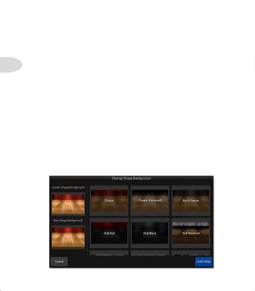
H. Change Stage Background. Tap this button and the Change Stage Background
browser will be displayed. Browse to select a new stage background - tap Load Stage to
display it.
Page 23
Group Encoders
From time to time it may be useful to create a Group encoder. For example, if you wanted
to group three background vocal channels together, or a rhythm section, once you had a
good balance it would be convenient to raise or lower all 3 channels with one encoder.
Setup Mode
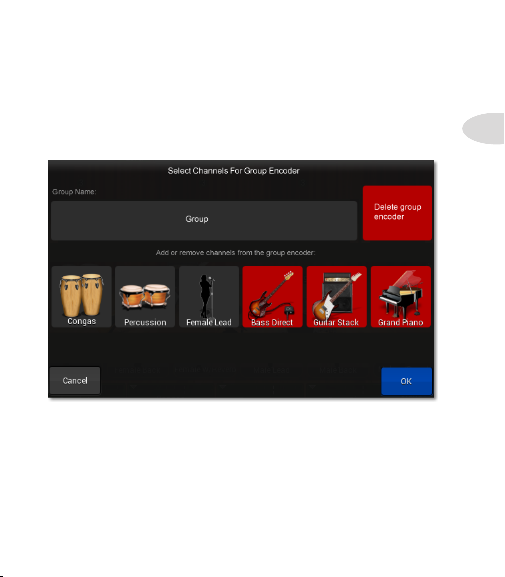
To create a Group encoder, double-press any unassigned hardware encoder. The Select
Channels For Group Encoder window will open, displaying all channels available for
grouping.
2•11
Tap the channel icons you’d like to include in the Group, which would be the Bass, Guitar
and Piano in the above example. Name the Group in the Group Name field, then click
the blue OK button.
A Group controller strip will appear in the M20d stage view, automatically assigned to the
hardware encoder you originally double-pressed. Now you can adjust all 3 channels with
the one Group encoder.
Page 24
Setup Mode
Channel Presets Overview
The M20d characterizes each input and output connection as a channel. Channels are
visually stylized as recognizable gear, referred to as Stage Icons, which you can select from
the Stage Icon Gallery.
2•12
With the M20d, a Channel Preset is the collection of properties that define a channel. This
includes its icon image, name, input or output jack assignment and its signal processing
settings. Each item within the Stage Icon Gallery represents a Channel Preset. Note that
while the M20d provides hundreds of Channel Presets to meet almost any live sound need,
you can customize every aspect of a channel and store your own personalized Channel
Presets.
Managing Stage Icons within the Stage Icon Gallery
If you find that the Stage Icon Gallery provides more Stage Icons than you will ever need,
you may wish to remove some of them. On the other hand, you may wish to add icons.
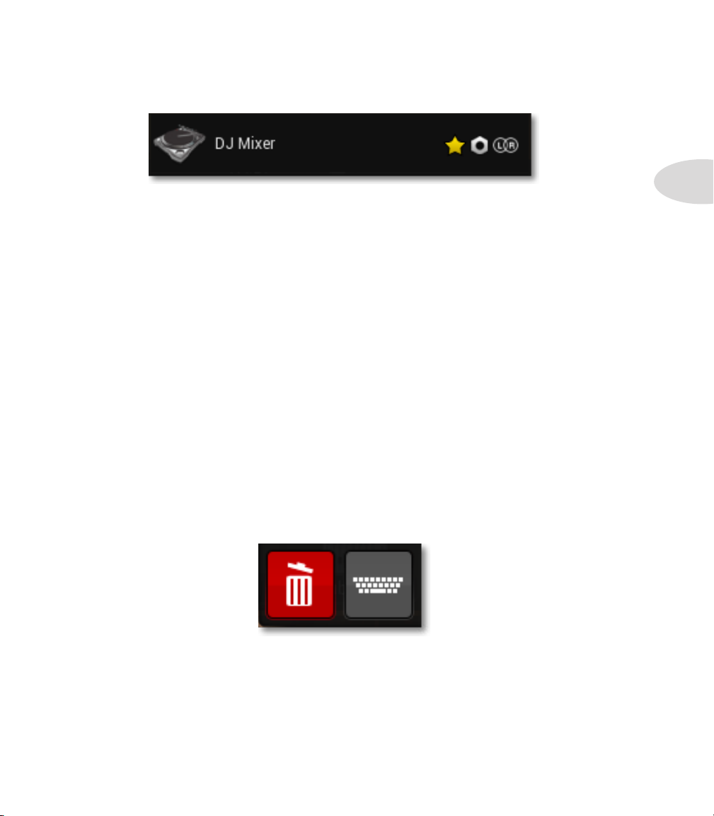
Additionally, it is possible to mark icons that you use frequently as “Favorites”.
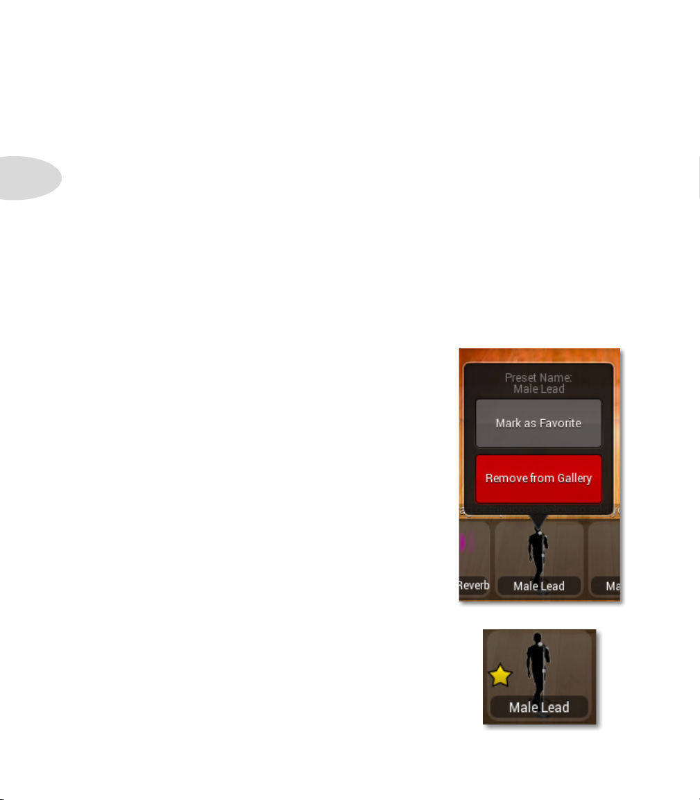
To remove an item from the Stage Icon Gallery:
1. In the Stage Icon Gallery, Press+Hold the Stage
Icon you wish to remove.
2. Wait for the item’s context menu to appear
3. From the context menu, tap the Remove from
Gallery button
You will observe that the icon is removed from the
gallery.
Note: This operation does not permanently remove the
item from StageScape’s preset library.
To mark an item as a “Favorite” within the Stage Icon
Gallery:
Repeat the above steps, but this time tap the Mark as
Favorite button in Step 3.
You will observe that a yellow star appears adjacent to
the Favorite icon within the gallery.
Page 25
Accessing the complete Preset Library via the ‘More...’ Icon
The Stage Icon Gallery provides easy access to Channel Presets for the most common
types of input and output devices required in live sound. However, presets referenced
within the Icon Gallery represent only a fraction of all the presets available to you. The
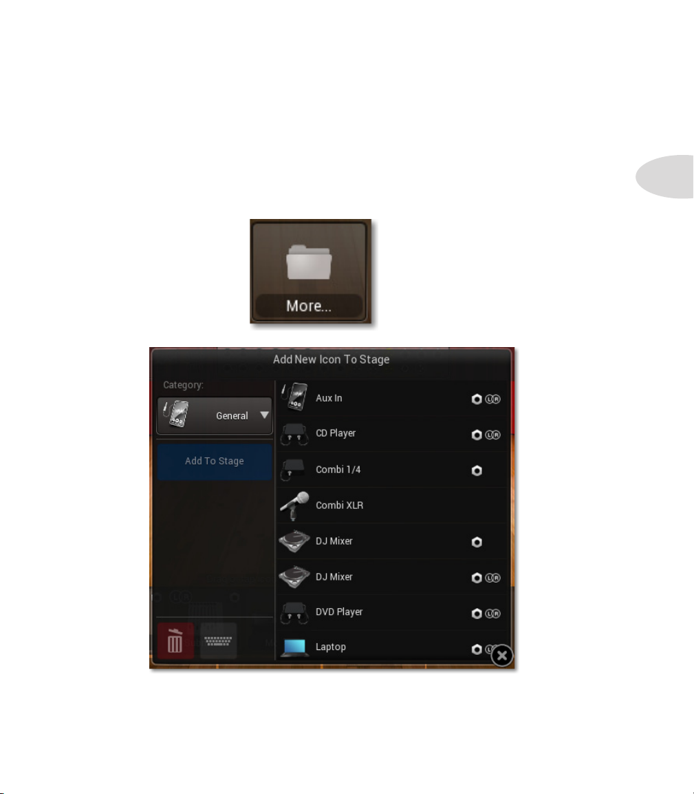
last item in the Stage Icon Gallery is a folder icon labeled, “More...”, which contains the
entire library of Channel Presets.
To access the complete Channel Preset Library:
Scroll to the end of the Stage Icon Gallery, so that you see the More... icon. Tap it.
The Preset Library dialog will appear over the Stage View.
Setup Mode
2•13
The Preset Library dialog allows you to add any of its presets to the Stage View, as well as
replace the preset of any Stage Icon on the stage.
Page 26
Setup Mode
2•14
To add a new icon to the Stage View from the Preset Library dialog:
1. Select a preset category using the Category menu located in the top-right of the
dialog.
2. Select a preset from the preset list in the right side of the dialog.
3. Tap Add To Stage.
You will observe that the dialog is dismissed and the Stage Icon for the selected preset
appears on the stage.
To replace a Stage Icon’s preset from the Preset Library dialog:
1. In the Stage View, select the Stage Icon whose preset you wish to replace.
2. Select a preset category using the Category menu located in the top-right of the
dialog.
3. Select a preset from the preset list in the right side of the dialog.
4. Tap Load Selected.
Observe that the dialog is dismissed and the selected Stage Icon’s channel preset is
replaced.
Tip : Note that the M20d retains the channel’s image and name if you had modified
the image or name prior to selecting a new preset.
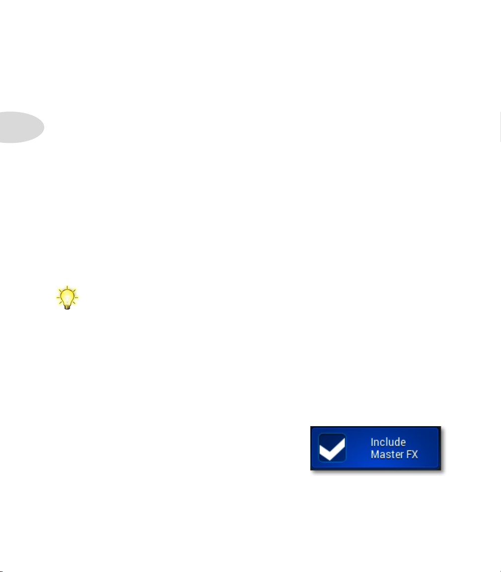
Include Master FX
When loading a new preset, the M20d provides the option of including the preset’s Master
FX settings. This is useful for loading Channel Presets that were designed with specific
Master FX settings in place, such as “Female w/Reverb” and “Male Doubled”.
To include Master FX replacing a Stage Icon’s preset from the Preset Library dialog:
1. Enable the Include Master FX option
2. Select a preset from the preset list
3. Tap Load Selected
Important: Be aware that Master FX are global,
meaning their settings affect all channels using
Master FX.
Page 27
Channel Presets Information
Channel Presets listed in the Preset Library reveal detailed information about themselves:
Icon image
A thumbnail image of the preset’s Stage Icon image reference.
Name
The Channel Preset’s name.
Favorite badge
If present, indicates that the preset has been marked as a Favorite.
Line-compatible badge
If present, indicates that the preset’s channel processing is compatible with Line Inputs
13 - 16.
Stereo badge
If present, indicates that the preset operates in stereo, intended for two adjacent inputs.
Setup Mode
2•15
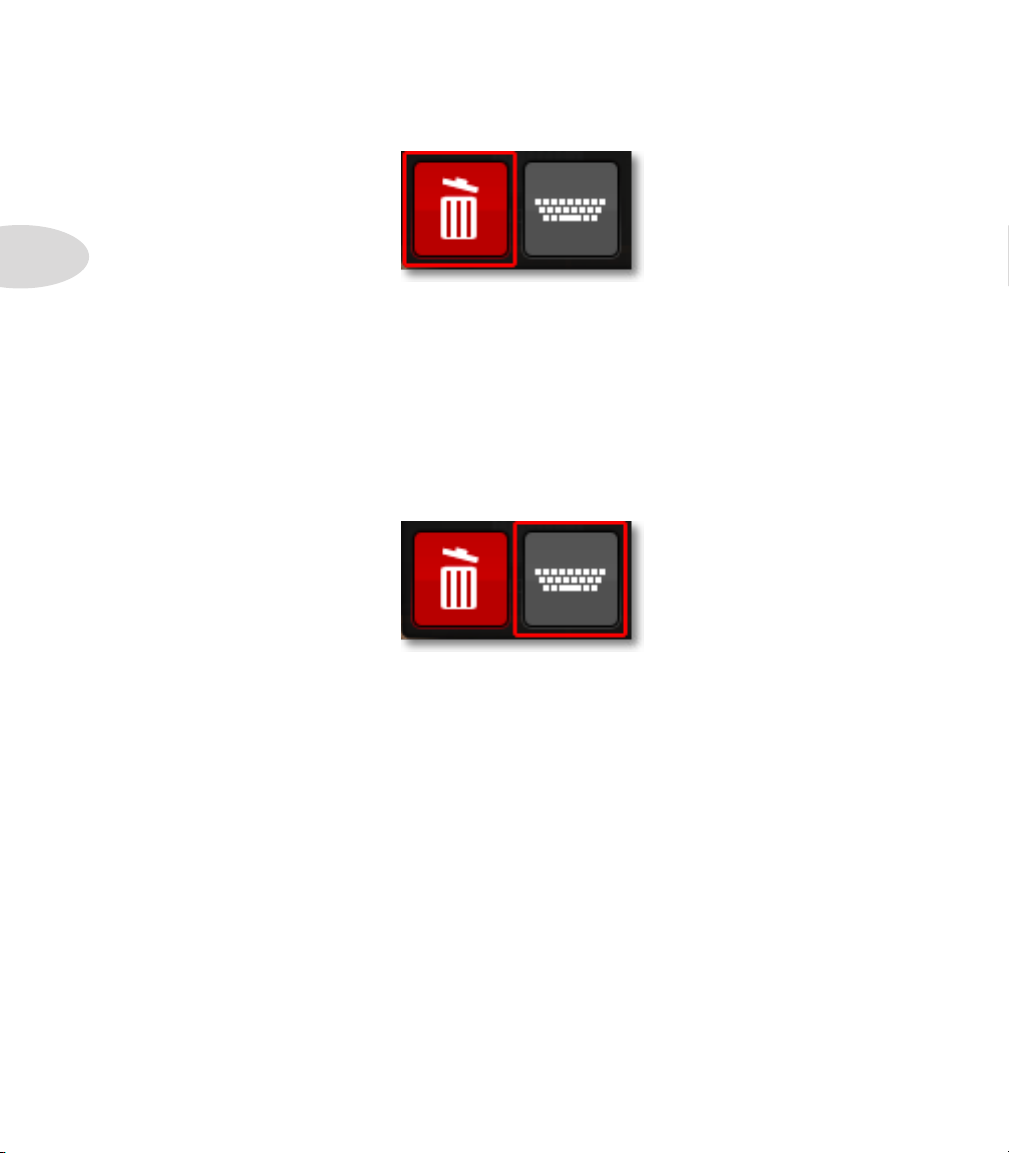
Deleting and Renaming Channel Presets in the Library
The M20d allows you to perform housekeeping on your preset library using Delete and
Rename operations. These operations can be useful if you amass a large library of custom
presets, or discover that many of the presets in your library go unused.
Warning: When you delete a preset, it is permanently removed from the Preset Library as
well as from the Stage Icon Gallery. It is advised that you periodically backup your presets
and settings so that you can safely restore presets at any time. Please see System Settings
for more information.
Page 28
Setup Mode
2•16
To delete a preset from the Preset Library dialog:
1. Select the preset in the preset list that you wish to delete.
2. Tap the Delete button in the bottom-left of the dialog.
3. Tap OK to confirm deletion.
Observe that the preset is deleted from the Preset Library list view
To rename a preset in the Preset Library:
1. Select the preset in the preset list that you wish to rename.
2. Tap the Rename button in the bottom-left of the dialog.
3. Enter the new preset name in the popup keyboard.
Observe that the new name is applied to the preset in the Preset Library list view.
Page 29
Tweak Mode
tweak MOde
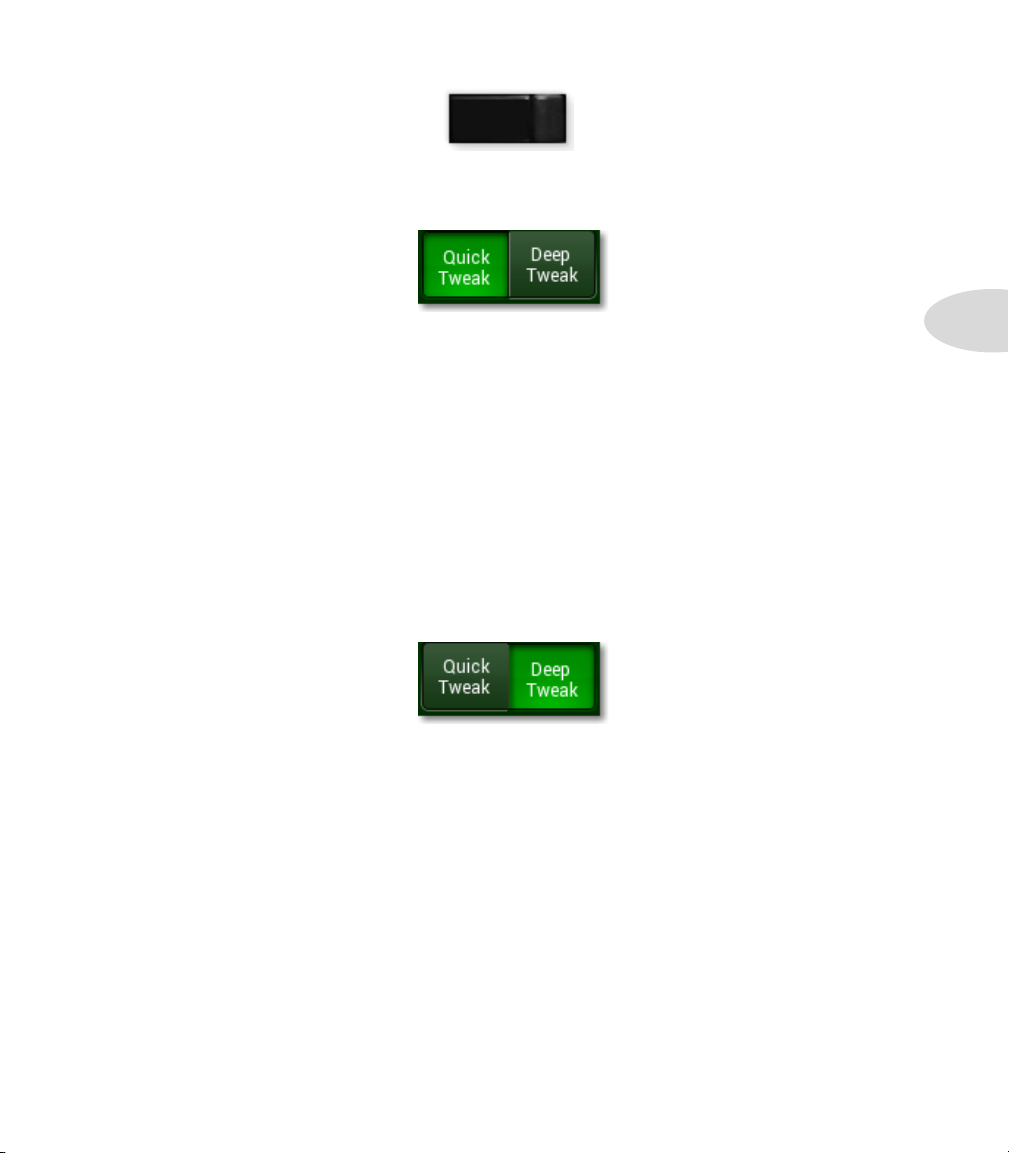
To enter Tweak Mode, press the M20d hardware TWEAK button on the front panel.
Tweak Mode offers 2 levels of adjusting channel parameters: Quick Tweak and DeepTweak.
TWEAK
Quick Tweak Overview
Quick Tweak is a fast, intuitive editing environment featuring a ‘smart’ multi-parameter
XY Pad. The XY controller enables you to dial in processing such as EQ, dynamics and
modulation with ease. Drag a finger toward common sound descriptors like “bright” or
“dark” and multiple parameters adjust simultaneously to achieve the desired sound.
The individual processors available for each channel in Quick Tweak mode are selectable
as tabs in the left area of the touchscreen. For example, if a vocal channel is loaded, tabs
for Punch, DeEsser and Tone are available, along with a simplified version of Global FX.
Tap one of the processor tabs and its XY Controller UI will be displayed. Then simply drag
your finger to the desired location on the touchscreen to tweak your sound. There are a
total of 8 XY processor presets available, depending on which DSP channel type is seleted.
SeePage3•2thru3•5forscreenshotsofall8XYprocessorsplustheGlobalFXUI.
3•1
Deep Tweak Overview
Deep Tweak enables you to access individual processor parameters to edit your channels
in finer detail. Each of the parameters displayed on the touchscreen for the currently
selected effect is matched to an M20d hardware encoder. The encoders are color-coded to
easily see which effect parameter each encoder will adjust.
The effect tabs for the currently selected channel are located in a row on the left side of
the touchscreen. Scroll up or down to see them all. Select an effect tab by tapping it and
its UI will be displayed on the touchsceen. The M20d hardware encoders will light up
accordingly, matching their associated parameters for fine adjustment.
In addition to fine-tuning your channel processing, Deep Tweak lets you tweak your Global
FX and Monitors. A dedicated Tweak button is available for each, providing parameter
control of the currently loaded Global FX, plus HiPass Filter, EQ 6 and Limiter for
Monitors, plus L6 LINK 31-Band EQ when a StageSource™ series speaker is connected.
Page 30
Tweak Mode
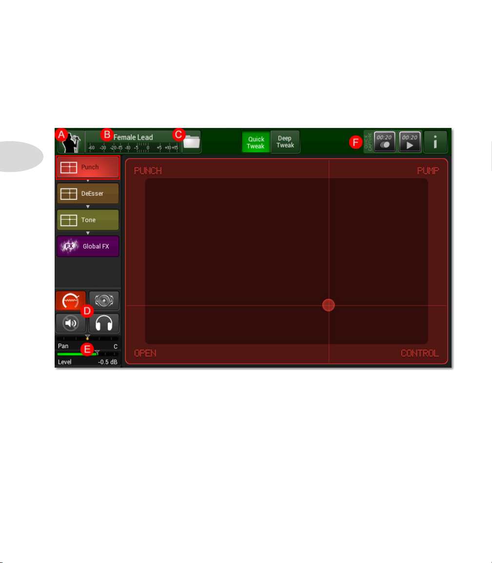
Quick Tweak
Punch (controls the Comp; confirm Trim Tracking is on to ensure correct Trim level)
3•2
After entering Tweak Mode, tap the green Quick Tweak button. As described on Page
3•1, the XY Touch Pad UI is displayed for each processor tab on the left. Simply drag
your finger across the screen to get the desired sound. The Punch UI is displayed below.
Other Quick Tweak UI functions include the following:
A. Edit Preset Properties
B. Select Channel (to Tweak)
C. Load/Save Preset
D. Trim Tracking, FBS Enable, Mute & Solo Buttons
E. Pan & Level Controls
F. Quick Capture Buttons
Page 31

A. Edit Preset Properties
Click the Channel Icon in the upper left
corner of the Tweak view and the Edit
Preset Properties window will open.
In Quick Tweak Mode, this window is exactly
the same as the Edit Preset Properties window
available in the Main Toolbar in Setup Mode.
Tweak Mode
Tap the Name field to change the current
channel name, or tap the Icon field to change
the current channel’s icon image.
The same contextual browsers will open as
with the Main Toolbar version of the Edit
Preset Properties window.
B. Select Channel
Click the name of the currently selected
channel above the level meter, as
illustrated on the previous page, and the
Select Channel browser will open.
Tap the channel you’d like to tweak. Input Channels, Output Channels, and
Global FX are available via the 3 buttons as illustrated below.
3•3
Page 32

Tweak Mode
C. Load/Save Preset
3•4
D. Trim Tracking, FBS Enable, Mute & Solo Buttons
Tap the Folder Icon to the right of the Channel Name to
open the Load/Save Presets window.
Tapping Load Preset will open the Load Preset browser,
with options to load a Preset from the Preset Library,
Delete or Rename the Preset, and other functions
described in detail on Page 2•13 in Chapter 2: Setup
Mode of this Guide.
Tap Save Preset to save the current preset to the Preset
Library, replacing the Factory Preset on which it is based.
Tap Save Preset As... to name and save the current preset
to the Preset Library.
These 4 buttons enable Trim Tracking, Feedback
Suppression, Mute On/Off, and Solo/On Off. See more
details on Trim Tracking and Feedback Suppression in
the Deep Tweak section of this chapter.
E. Pan & Level Controls
Set Channel Pan position with this control, which is
matched to hardware encoder #1, color-coded yellow.
Set Channel Level using encoder #7, color-coded green.
F. Quick Capture Buttons
These buttons are full time Quick Capture transport controls. Tap the Record
button at any time to capture 20 seconds of live audio to the M20d’s internal
memory. Tap the Play button to play it back. Playback will loop continuously
until you tap Stop. If your press Record again, the previously captured audio will
be replaced by the new recording.
Quick Tweak XY Processors
In addition to Punch, illustrated on Page 3•2, the other Quick Tweak processors
available via the left row tabs are illustrated on the following pages, beginning with Tone.
The available processors depend on which Channel Preset/DSP Type is loaded.
Page 33

Tone (depending on channel type, XY controls a 6 Band, 4 Band, or 3 Band EQ)
DeEsser (removes sibilance frequencies, usually in the 5K-8K range)
Tweak Mode
3•5
Page 34

Tweak Mode
Flanger (XY controls the channel Flanger)
3•6
Chorus (XY controls the channel Chorus)
Page 35

Megaphone (XY controls the megaphone effect)
Echo (XY adjusts the Delay Time, Feedback, and Mix for the channel Delay)
Tweak Mode
3•7
Page 36

Tweak Mode
SubBass (Sub boosts 60 Hz, Boom boosts 80 Hz, and Thump boosts 90Hz)
3•8
MultiComp (XY morphs between 5 different settings of the Multiband Compressor)
Page 37

Deep Tweak
When you tap the green Deep Tweak button in Tweak Mode, you have access to all
individual parameters of the currently selected processor. Each parameter displayed on the
touchscreen is assigned to an M20d hardware encoder, which is color-coded to match it.
Below is an example featuring page 1 of the EQ 6 user interface. (See the following pages
for descriptions of items G, H, I and J.)
Tweak Mode
3•9
Pan
100%L ~ 100%R 20Hz ~ 500Hz -15dB ~ +15dB 20Hz ~ 18kHz 0.1q ~ 10.0q -15dB ~ +15dB
Level
Off ~ +12dB 20Hz ~ 18kHz 0.1q ~ 10.0q -15dB ~ +15dB
Low Freq Low Shelf Mid Freq 1
Mid Freq 2
Mid Q 1
Mid Q 2
Mid Gain 1
Mid Gain 2
Page 38

Tweak Mode
3•10
To edit any of the processors in the currently selected channel’s signal chain, tap its tab in
the scrollable left row. Swipe up or down to see all the available tabs.
For a comprehensive list of all M20d Channel Processing available in Deep Tweak mode,
including all parameters, ranges and assigned hardware encoders, please see Appendix A:
Channel Processing in this M20d Advanced Guide.
G.Edit Preset Properties Window
When the green Deep Tweak button is selected, tapping the channel icon opens an
expanded version of the Edit Preset Properties window, which includes selection of the
Preset Category, Subcategory and Preset DSP Type, as illustrated below.
Preset Category and Subcategory are selectable via drop down menus. Tapping the
blue Preset DSP Type button opens the Change DSP Type browser, which is described
in depth in Appendix C: Preset DSP Types in this M20d Advanced Guide, and also
includes details on all the Preset DSP Types available in the M20d.
Otherwise, regarding changing the Preset Name and Icon image, this window functions
the same as the version that appears when the green Quick Tweak button is selected, (as
described on Page 3•3).
Page 39

H.Input Settings
When you tap the Input tab in Deep Tweak mode, you have access to the following:
Tweak Mode
3•11
1. Invert Polarity: reverses the phase of the selected channel.
2. Auto Trim: opens the Auto Trim window (see Setup Mode, Page 2•8 for details).
3. Trim Tracking: when Trim Tracking is on, if the channel’s input level is too hot,
Input Trim is automatically lowered to prevent clipping. A smart DSP algorithm
makes sure that the the perceived and displayed Trim level does not change.
4. Input Trim: this is the manual Input Trim setting, adjustable using encoder #2.
5. Highpass Filter Enable: drag to set the highpass filter frequency, or use encoder #3.
6. FBS Reset: resets the Feedback Suppression settings.
7. FBS Enable: enables Feedback Suppression for this channel.
8. Global Feedback Detection Mode: sets detection mode to Universal or Vocal, using
encoder #6.
Page 40

Tweak Mode
3•12
I.Monitor Settings
When you tap the Monitors tab in Deep Tweak mode, the Monitor settings are displayed.
1. Monitor Icon: displays the stage icon for the connected monitor.
2. Tweak Button: click Tweak to display the Tweak view for the selected Monitor. See
the illustrations on the next page for visual details. In Quick Tweak mode, the Tone
XY interface is displayed. In Deep Tweak mode, you can fine tune the processors
selectable in the left row of processor tabs, similar to tweaking an input channel.
3. Linked/Unlinked Button: sets the monitor mode to Linked or Unlinked. Linked
is Post-fader: when you adjust the channel level up or down, the monitor level is
adjusted up or down accordingly. Unlinked is Pre-fader: when you adjust channel
level up or down, it has no effect on monitor level.
4. Output Level: adjusts the output level of the selected monitor, using the associated
M20d hardware encoder in the top row of the front panel.
5. Send Level: adjusts the level of the channel’s audio that is sent to the selected
monitor, using the associated M20d hardware encoder in the bottom row of the
front panel.
Page 41

Monitors View when Tweak button is pressed, in Quick Tweak mode
Monitors View when Tweak button is pressed, in Deep Tweak mode
Tweak Mode
3•13
Page 42

Tweak Mode
3•14
J. Global FX Settings
When you tap the Global FX tab in Deep Tweak Mode, you have access to the Global FX
settings, which are slightly more comprehensive than in Quick Tweak Mode.
1. Load FX Preset Button: tap to open the Load FX Preset browser. You can then
select which effect is loaded into FX A, FX B, FX C or FX D. For more detail and a
complete list of all Global FX and their parameters, please see Appendix D: Global
FX in this M20d Advanced Guide.
2. Tweak Button: click Tweak to display the Tweak view for the selected effect. See
the illustrations on the next page for visual details. In Quick Tweak mode, the
simple XY interface for the loaded effect is displayed. In Deep Tweak mode, you can
fine tune the loaded effect’s parameters or select the Monitors tab.
3. Return Level: adjusts the global return level of the selected effect, using the associated
M20d hardware encoder in the top row of the front panel.
4. Send Level: adjusts the level of the channel’s audio that is sent to the selected effect,
using the associated M20d hardware encoder in the bottom row of the front panel.
Page 43

Global FX View when Tweak button is pressed, in Quick Tweak mode
Global FX View when Tweak button is pressed, in Deep Tweak mode
Tweak Mode
3•15
Page 44

Tweak Mode
Media Player
When either an SD Card or USB Drive is connected to the M20d
I/O Panel, a Media icon appears on the stage, and a Media Player
controller strip is automatically assigned to it. In all modes the
Media Player behaves like any other input channel, so you can
adjust mix level, monitor level, mute, solo, etc.
There are rwo ways to access the Media Player interface:
3•16
1. In Setup Mode, select the Media stage icon then tap the Tweak Media Player
button in the Main Toolbar.
2. In Tweak Mode, select the Media Player tab in the left column of processor tabs.
This is the Media Player UI. In this example the current Playlist consists of 3 songs. Song
2 is playing back.
Page 45

Add Files To Playlist
Tap the Add files to playlist button to access the File Browser for your connected
Removable Media. You can then create a Playlist from scratch, or add songs to a
current Playlist. Tap the USB Thumb Drive icon to ‘drill down’.
Any stored song files will be displayed in a list, as illustrated below. Select songs to
add them to the Playlist, then tap OK.
Tweak Mode
3•17
Page 46

Tweak Mode
3•18
Songs7and9fromthepreviousstephavebeenaddedtothePlaylist,andSong7isplaying
back. The other transport controls function like any other playback transport.
To remove a song from the Playlist, simply select it and tap the Remove selected button.
To clear the Playlist, removing all songs, tap the Clear playlist button.
Page 47

Record Mode
recOrd MOde
Enter Record Mode by pressing the M20d hardware RECORD button. In Record Mode
the M20d offers three main record and playback options, as follows:
1. Quick Capture: record up to 20 seconds of 24 bit unprocessed audio at 48kHz to
the M20d’s internal memory, and play it back.
2. Recording: record 20 channels of 24 bit unprocessed audio at 48kHz, including the
Aux inputs and main mix, to SD Card or USB Hard Drive, and play it back (when
media is inserted into the M20d SD Card slot or USB port).
3. Streaming: stream 20 channels of 24 bit unprocessed audio at 48kHz, including the
main mix, to a computer via USB, with a stereo return stream back to the M20d.
When you enter Record Mode, the M20d’s Main Toolbar displays the Encoder Assign
button, the Configure Record/Playback button, the Record transport controls, the
numerical Record/Play Counter and the Info button. Below is a screenshot of the
M20d’s touchscreen in Record Mode, using a Duo stage setup as an example.
RECORD
4•1
When there is no SD/USB media inserted, Record Mode defaults to Quick Capture.
Page 48

Record Mode
Quick Capture
4•2
Quick Capture In Tweak Mode
Using Quick Capture you can record up to 20 seconds of live audio to the M20d’s internal
memory. As a visual cue that you’re in Quick Capture mode, the Record button appears
with a 00.20 indicator. All tracks are recorded when you tap the Record button, so no
track arming is required.
Press Play and your recorded tracks play back through the channels you have set up on
your M20d. Since the tracks are recorded unprocessed, you can adjust channel settings as
you listen back. Playback will loop continuously until you press Stop.
Quick Capture is useful for recording a live sound check, for example. It enables you
to listen to your recorded mix and adjust mix settings as needed. And when using the
StageScape Remote app with an iPad®, you can listen to your mix from various locations
around the room. The recorded audio is replaced each time you press Record.
In addition to Record Mode, where Quick Capture is available only when no SD or
USB media is inserted, Quick Capture is always available in Tweak Mode.
For example, if you’re adjusting EQ settings for a Vocal channel in Tweak Mode, you can
instantly capture the vocalist’s live audio by tapping the Quick Capture Record button
in the upper right of the display.
See the Tweak Mode chapter for more info on Quick Capture in Tweak Mode.
Page 49

Record/Playback Configuration
To configure Record/Playback for the M20d’s three available recording modes, tap the
Configure Record/Playback button in the Main Toolbar.
This opens the Record/Playback Configuration window.
Record Mode
4•3
The Record/Playback Configuration window provides access to the following settings:
• Record/Play Mode: select Quick Capture, USB to Computer or SD/USB Media.
Page 50

Record Mode
4•4
Quick Capture will be selected by default if no SD or USB media is connected. USB
to Computer can be selected for streaming audio if a USB hard disk is connected to the
M20d. SD/USB Media can be selected if an SD card or a USB hard drive is connected
to the M20d.
*Note that USB stick/thumb drives or bus powered USB drives are not supported. SD
Cards must be rated Class 10 or above.
• External Storage: enables media storage selection via a file browser. Tap the
button then drill down to the appropriate folder you’d like to use for your recording
destination.
• New Recording Name: enables naming the new recording. Tap the button and
a text keyboard window will open. Type in the recording name then press Enter.
• Recording Source: enables selection of recording source, either Inputs Only,
Main Mix Only, or Inputs and Main Mix.
Page 51

Record Mode
• Recording List: a list of recordings located on the selected SD card or hard drive
appears in this window. Select a recording in the list to play it back. All new
recordings are automatically added to the list.
• Selected Take: a Take is a sequential recording of a particular song with the same
name, such as “Slow Song” 1 (take 1), “Slow Song” 2 (take 2). If more than one take
of a song is recorded, each take would be listed here, selectable for playback.
Recording Times
The following table lists the maximum recording times available per SD Card/ Hard Drive
storage capacity.
Inputs & Main Mix Inputs Only Main Mix Only
Capacity 20 Channels 18 Channels 2 Channels
4 GB 24:54 27:36 248:36*
8 GB 49:42 55:12 248:36
16 GB 99:24 110:30 248:36
32 GB 198:48 220:54 248:36
Recording times are listed in minutes:seconds.
*248:36 is the M20d’s maximum recording time.
4•5
M20d will not record if SD card/hard drive has less than 64 MB of free space available.
Page 52

Record Mode
Recording
Transport Controls
4•6
Record/Play Counter
When an SD card or USB hard drive is plugged into the M20d, it is possible to record
20 channels of audio to the SD card or hard drive and play them back. This includes 16
Input channels, the stereo Aux inputs, and the Main Mix output.
The Main Mix includes all processing, but the other 18 channels are pre-fader preprocessing. They will play back through the M20d’s channels, so parameter adjustments
can be made in real time.
With SD/USB Media present, the M20d transport controls include the standard Play,
Stop and Record buttons. Play is only available when a recording is selected.
The Record/Play counter indicates the elapsed time of the current recording file, displayed
in hours:minutes:seconds.
You can navigate into a recorded file during playback by tapping the counter, then using
the scroll bar to navigate to the desired location of the recording.
Playing Back A Main Mix Recording
A Main Mix recording can only be played back using the Media Player in Tweak Mode.
To play back a Main Mix recording, first select the Media Player icon on the stage, then
press the Tweak button.
Tap the Media Player tab and the Media Player UI will be displayed. Tap the Add
Files To Playlist button, then navigate the File Browser until you find the Main Mix
recording you’d like to play back. Select it, then tap the blue OK button. This adds the
track to the list. Now just select it and press the Play button. Your track should play back
in stereo through channels 17 & 18..
Page 53

Recording Procedure
To record your M20d’s audio Input channels to an SD Card, follow these steps:
1. Insert a Class 10 or above SD Card into the M20d I/O Panel’s SD Card slot.
2. Enter Record Mode by engaging the hardware RECORD button.
RECORD
3. Tap the Configure Record/Playback button in the Main Toolbar (see Page 3).
4. Select SD/USB Media as your Record/Play mode.
Record Mode
4•7
5. Tap the External Storage button, then browse and select your record destination.
6. Tap the New Recording Name button then type in a recording name.
7. Tap the source button and select Inputs Only as your recording source.
8. Tap the X to dismiss the Record/Playback Configuration window.
9. Tap the Record button to start recording; press Stop when finished.
10. Tap the Play button to listen to your recording, making mix adjustments as desired.
Page 54

Record Mode
Streaming
The M20d will stream 20 channels of audio to your computer via USB, and receive a
stereo return stream back from your computer. The use case for this would be when you’d
like to record M20d unprocessed channels for editing in your DAW.
Input Streaming Configuration
The M20d streams 20 inputs to your computer and a stereo return stream back to the
M20d in the following input streaming channel configuration:
• Channels 1-16: M20d Mic/Line Inputs 1-16, pre-processing / pre fader
4•8
• Channels 17-18: M20d stereo Aux Input, pre-processing / pre-fader
• Channels19-20:M20dstereoMainOuts,post-processing/post-fader
USB Stereo Return Stream:
The stereo return is streamed to the M20d’s stereo Aux Input (channels 17/18).
Note: In order to hear the stereo return, a Stage Icon Preset must be assigned to the Aux
Input using the M20d touchscreen UI. The Laptop preset is ideally suited for this purpose,
and can be found in the Stage Icon Gallery.
For USB audio streaming, you must download and install the Line 6 StageScape
M20d Driver at http://line6.com/software.
On that page you will find 3 drop down menus. On the All Products drop down menu
select M20d StageScape. On the All Software drop down menu select Drivers.
On the last drop down menu select the operating system of the computer you wish to use
with your M20d StageScape. Once the download has completed, find and run the M20d
StageScape Drivers Installer, then follow the onscreen installer directions.
In your DAW you will need to change your audio interface to ASIO M20d StageScape. Then
create new audio tracks in your DAW with inputs that correspond to the inputs on the
M20d. Note: If you are using the StageScape DX/MME driver, make sure that StageScape
is selected as the default audio device in Windows. Also, know that you will only get
audio from inputs 1-2 if you are recording with DX/MME.
The Windows StageScape M20d USB 2.0 audio driver uses WDM and ASIO, supported
on 32 and 64 bit OS configurations. The Mac OS X StageScape M20d USB 2.0 audio
driver uses CoreAudio, supported on 32 and 64 bit OS configurations.
Page 55

M20d Monitor Mode
MOnitOr MOde
In most live performance setups it’s common to route audio from select channels to onstage
monitor speakers, so the performers can hear themselves and specific elements of the mix.
With the M20d, when you want to route audio from your input channels or global FX to
your monitor speakers, you have two options:
Option 1: when adjusting a single channel’s processing in Deep Tweak mode, tap the
Monitors tab to adjust monitor Send Level and Output Level for that particular channel.
Option 2: to adjust Monitor levels for all of the channels in your setup on one screen,
press the hardware Monitor button and enter Monitor Mode. Your display will look
something like this (using a Duo stage setup example):
MONITOR
5•1
In Monitor Mode, all channel and global FX monitor levels are available in one screen view, so monitor level adjustments can be made quickly and easily. In the above illustration the selected monitor’s controller strip and target triangles pulsate in blue.
Page 56

M20d Monitor Mode
Channel Monitor Levels
In Monitor Mode, all channel controller strips are dedicated to monitor functions.
They’re colored blue, as are their assigned hardware encoders. Also, the controller strips’
Mute/Solo buttons that are displayed in Record Mode and Perform Mode are replaced
by Linked/Unlinked buttons.
Linked/Unlinked Buttons
When a channel is in Linked mode, channel level is displayed along with monitor level,
and the two levels maintain their relative settings when channel level is adjusted. When
a channel is in Unlinked mode, its monitor level is independent of its channel level, so
when its monitor level is set to a particular value, that setting won’t change when you
increase or decrease its channel level.
5•2
An easy way to think of the Linked/Unlinked concept is that Linked is post-fader and
Unlinked is pre-fader. In other words, when a channel is Linked, its monitor level is
relative to its channel level, so a baseline monitor mix can easily be established, since it
will be the same as the main mix. Incremental adjustments can then be made quickly,
i.e. just turn up the vocals a little more, and the monitor mix will replicate the main mix.
Most input channels are in Linked mode by default, but channels such as guitar amps, that
are usually loud on stage, default to Unlinked mode.
Graphically, when in Linked mode, channel level is displayed as a secondary horizontal
band (set to -0.1 dB in the above left illustration). In this example, it extends to the right
of the small triangle that indicates monitor level.
When monitor level is set higher than channel level (above right), a red band will be
displayed between the blue channel level band and the triangle monitor level indicator.
When channel level and monitor level are equal, the triangle indicator will be colored
Page 57

M20d Monitor Mode
green. If monitor level is turned off while the channel level is up, the monitor level stays
off until it is turned up again.
In Unlinked mode, only monitor level will be displayed as a blue horizontal band, without
channel level, as illustrated below. In either mode, live audio level will always be displayed
in the horizontal strip below the monitor level band.
Routing Channel Audio To A Target Monitor
In Monitor Mode there are 3 easy steps involved in sending a channel’s audio to a target
monitor, as follows:
1. Select the target monitor on the stage by tapping it.
5•3
2. Set the source channel’s Linked/Unlinked mode as desired by tapping its button.
3. Turn the source channel’s assigned encoder to the desired monitor level.
As you adjust each channel’s monitor level, you’ll see an animated signal flow displayed
from the source channel to the target monitor.
To route audio to a different target monitor, simply tap the monitor’s icon on the stage and
you’ll see its controller strip pulsate bright blue, along with the target triangles that rotate
around the monitor’s stage icon (see page 1). Then adjust the source channel’s monitor
level as desired by turning its assigned hardware encoder.
Routing Media Player Audio To A Target Monitor
If you’re using a media player in your M20d setup and would like to route its audio to
the monitors, it can be treated exactly the same as any other channel. Select the target
monitor, set the media player’s Linked/Unlinked mode on its controller strip, then adjust
its monitor level as desired by turning its assigned hardware encoder.
Page 58

M20d Monitor Mode
FX Monitor Levels
In Monitor Mode, you can also route audio from any of the 4 global FX to your monitors.
To do so, tap the FX To Mons button located in the upper left of the Main Toolbar. The
4 global FX controller strips will appear, as illustrated below.
5•4
Now follow the same 3 basic steps previously outlined for Channel Monitor Levels:
1. Select the target monitor on stage by tapping it.
2. Set the source effect’s Linked/Unlinked mode as desired by tapping its button.
3. Turn the source effect’s assigned encoder to the desired monitor level.
As you turn each effect’s hardware encoder, which will be color-coded purple, you’ll see
the animated signal flow from the source effect to the target monitor, as illustrated in the
above screenshot for FX A.
Page 59

Perform Mode
perfOrM MOde
Press the M20d hardware PERFORM button to enter Perform Mode.
In Perform Mode the focus is on performance mixing. Stage icons are locked into
position, so you can’t move them around or perform other setup functions such as creating
channels, replacing, resizing or renaming stage icons, or accessing the I/O Panel.
PERFORM
6•1
The general M20d workflow would be to set up all your channels in Setup Mode, tweak
individual parameters and FX processing in Tweak Mode, adjust monitor levels in Monitor
Mode, then mix your live performance in Perform Mode.
The basic functions available in Perform Mode are as follows:
• Saving & Loading Scenes (including deleting and renaming them)
• Encoder Assignments (control of Channel Level, Pan, Trim, and Global FX levels)
• Mute & Solo (Mute on/off; Solo on/off)
Page 60

Perform Mode
You still have access to the Info View in the Main Toolbar, from which you can select
Help, Footswitch Assign, L6 LINK Device Management and System Settings. And
you still have the ability to select Channels, Stage Icons, the Mains Meter and Media
Player if you’d like to edit your selection in Tweak Mode.
Saving & Loading Scenes
The Scenes button is located in the upper left corner of the Main Toolbar in Perform
Mode, replacing the Setups button featured in Setup Mode. A Scene is essentially a
snapshot of all your settings within the current Setup. These include settings for processor
and FX parameters, channel levels, mute, solo, pan position and monitor level. There is
no limit to the number of Scenes you can store within a Setup.
6•2
Tip: tap and hold any Controller Strip for a few seconds - it will turn grey, indicating
you can then drag it to rearrange its order (its assigned encoder will track it).
To save a Scene, tap the Scenes button. The Save & Load Scenes window will open. If
no Scene has yet been saved, tap the Save button and you’ll be able to name the current
Scene. After typing in the Scene name, tap the Enter button and your Scene will be
saved for future recall.
Page 61

Perform Mode
One scenario for using multiple Scenes in a live performance scenario would be to save a
separate Scene for each song in your set. You may want to change only the vocal reverb
level for one song, for example, or mute the drums for a song that features only vocals and
acoustic guitar.
Each Scene could be named after the song it represents, and if you assign a footswitch to
advance your Scenes one at a time, you could step through an entire set of custom mixes
by tapping the footswitch before each song.
6•3
In the Save & Load Scenes window you can Save the current Scene, Save As, or
Reload Current Scene.
You can also delete the selected Scene, which calls up a Confirm dialog, or tap the
keyboard icon to rename the selected scene, which calls up a text keyboard.
Tap to delete Scene Tap to rename Scene
Page 62

Perform Mode
Encoder Assignments
Once a Scene is loaded, or if you’re using the current settings as your default Scene, you’ll
be in mix mode. During a live performance you’ll most likely be tweaking encoder levels.
The M20d makes it easy to switch encoder assignments, giving you quick access to the
following via the Encoder Assign button in the Main Toolbar:
• Channel Level
• Channel Pan
• Channel Trim
• Global FXA Send Level
• Global FXB Send Level
• Global FXC Send Level
• Global FXD Send Level
6•4
Tap the Encoder Assign button and this drop down menu
will appear. Select the desired assignment for the channel
you’re working on and the encoder for that channel will
instanly control the parameter you’ve selected.
Switch to another assignment for any channel and adjust its
level using the same encoder. All channels will follow the
current encoder assignment. In other words, if Pan Position
is selected, all encoders will control Pan Position for their
assigned channels. The exception would be for channels
for which a particular assignment is not applicable.
An example would be the Media Player or the stereo Aux
Input channel, which have no Trim controls. In this case, the Media Player and Aux
Input controller strips would default to Channel Level.
Mute & Solo
To toggle the Mute/Unmute state for any channel, tap the Mute button on its controller
strip. Tap Show Solo Buttons in the Main Toolbar to convert the Mute buttons to
Solo buttons. Tap the Clear Solo button to defeat Solo, and tap Hide Solo Buttons to
toggle the Solo buttons on the controller strips back to Mute buttons.
Page 63

fOOtSwitcheS
The M20d provides two footswitch jacks, Footswitch 1 and Footswitch 2, which support
momentary types of footswitches.
Footswitch assignment options for both footswitches can be configured via the Footswitch
View, which is accessible from the following two places:
1. The Info menu (tap the Assign Footswitches menu item).
Footswitches
7•1
2. The I/O Panel (zoom in on the I/O Panel in Setup Mode by tapping it, then tap the F1
F2 jack area, upper-right).
Page 64

Footswitches
Footswitch View
7•2
The Footswitch View provides a list of assignment options for each footswitch. Assign
footswitch control to the designated footswitch by selecting one of its assignment options.
Assignment Options
Tap the appropriate button for Footswitch 1 or Footswitch 2 to configure each of the
following Assignment Options.
• FX Mute
• Scene
• Media Player
• Quick Capture
• Momentary Option
Page 65

FX Mute
The FX Mute assignment toggles mute ON and OFF for the designated Global FX. You
can select one or more Global FX for this assignment option. This is useful for quickly
muting FX between songs when addressing your audience, for example.
Footswitches
7•3
Scene
The Scene assignment enables you to load the Next Scene or Previous Scene, if using
Scenes in the current Setup. An application for this could be to quickly load the next
Scene prior to playing the next song in your set.
Page 66

Footswitches
Media Player
Quick Capture
7•4
The Media Player assignment provides audio playback control of songs within a playlist.
The Next Track option will advance playback to the next track in the current Playlist.
The Play/Stop option toggles playback off and on for the current track in a playlist.
Please refer to the Media Player topic for more information regarding playlists.
When assigned to Quick Capture, the footswitch controls audio recording and playback
when the M20d is in Quick Capture mode. The footswitch performs a sequence of
operations, beginning with a record operation by default.
The Quick Capture Footswitch Table on the following page provides an example of this
sequence.
Page 67

Quick Capture Footswitch Table
Step Footswitch Action Operation
1 Press Start Quick Capture recording
2 Press Stop Quick Capture recording
3 Press Start Quick Capture playback
4 Press Stop Quick Capture playback
5 Press Start Quick Capture playback
6 Press Stop Quick Capture playback
7 Press+Hold (about 2 seconds) Reset the footswitch sequence,
so that Step 1 occurs on the next
press
*Note: Steps 3 - 6 will repeat indefinitely until you Press+Hold the footswitch, as indicated
in Step 7.
Momentary Option
The Momentary button selects the desired behavior of the footswitch. This setting is
recommended for muting Global FX.
Footswitches
7•5
If Momentary is enabled, the mute will only be applied when the switch is down.
If Momentary is not enabled, each press of the footswitch will toggle the mute state.
Page 68

Page 69

Managing L6 LINK Devices
Managing L6 Link deviceS
If you’re using Line 6 StageSource™ series speakers with your M20d, you’ll want
to connect via L6 LINK for a totally digital system. The M20d supports L6 LINK
congurationsofupto18speakers,whichcaninclude9mainspeakersand9monitors.
Each L6 LINK connected speaker can be assigned to any of the M20d’s 6 outputs. This
means, for example, that an L6 LINK connected speaker assigned to Monitor A would
transmit the same audio that the M20d is transmitting to the Monitor A output.
Note: When a StageSource series speaker is assigned to an M20d output, the audio from
the speaker’s analog input is mixed with and transmitted through the speaker.
To configure your L6 LINK settings, tap the Info button in the Main Toolbar, then select
the Manage L6 LINK Devices tab. This will display the Configure L6 LINK window.
By default, Auto Assign L6 Link Speakers will be set to ON.
8•1
Page 70

Managing L6 LINK Devices
Auto Assign L6 Speakers: On
When Auto Assign L6 Link Speakers is set to ON, the M20d assigns L6 LINK connected
speakers to its outputs based on the type of speakers, the number of speakers connected,
and their position.
For Example, if only one L3t vertically oriented speaker is connected, the M20d will assign
it to L+R (Main Left + Main Right). If it is horizontally oriented, the M20d will assign it
to Aux A. If only one L3s (Sub) is connected, the M20d will assign it to L+R (Main Left
+ Main Right).
When a vertically oriented speaker’s position is inverted, vertically tilted, vertical or
unknown, it is assigned to M20d outputs according to Table 1 (see Page 3).
When a vertically oriented speaker’s position is 0° horizontal, 30° horizontal or 60°
horizontal, it is assigned to M20d outputs according to Table 2 (see Page 4). *Speaker tilt
angle refers to its flat orientation (0°) or leaning back on its handle or tilt stands.
8•2
StageSource L3s speakers (Subs) are assigned to M20d outputs according to Table 1.
Note: If a speaker’s orientation changes while Auto Assign L6 LINK Speakers is set to
ON, its orientation will not change within this view. In order to indicate any orientation
changes that may have occurred while Auto Assign L6 LINK Speakers is set to ON,
you must toggle the Auto Assign button OFF, then ON again. This is useful because it
allows you to change your intended orientations without changing your assignments.
Page 71

Managing L6 LINK Devices
Table 1: Default Output Assignments for Vertically Oriented L3t and L3m Speakers
Number
Of
Speakers
1
2
3
4
5
6
7
8
9
Default Output Assignment
Speaker 1Speaker 2Speaker 3Speaker 4Speaker 5Speaker 6Speaker 7Speaker 8Speaker
9
Mains
L+R
Mains LMains
R
Mains LMains
L+R
Mains LMains LMains RMains
Mains LMains LMains
Mains LMains LMains LMains RMains RMains
Mains LMains LMains LMains
Mains LMains LMains LMains LMains RMains RMains RMains
Mains LMains LMains LMains LMains
Mains
R
L+R
R
Mains RMains
R
Mains RMains RMains
L+R
L+R
R
R
R
Mains RMains RMains RMains
R
8•3
Page 72

Managing L6 LINK Devices
Table 2: Default Output Assignments for Horizontally Oriented L3t and L3m Speakers
8•4
Number
Of
Speakers
1
2
3
4
5
6
7
8
9
Default Output Assignment
Speaker 1Speaker 2Speaker 3Speaker 4Speaker 5Speaker 6Speaker 7Speaker 8Speaker
9
Aux A
Aux A Aux B
Aux A Aux B Aux C
Aux A Aux B Aux C Aux D
Aux A Aux A Aux B Aux C Aux D
Aux A Aux A Aux B Aux B Aux C Aux D
Aux A Aux A Aux B Aux B Aux C Aux C Aux D
Aux A Aux A Aux B Aux B Aux C Aux C Aux D Aux D
Aux A Aux A Aux A Aux B Aux B Aux C Aux C Aux D Aux D
Page 73

Managing L6 LINK Devices
Auto Assign L6 Speakers: OFF
You can toggle Auto Assign L6 Speakers to OFF by tapping the button. Doing this
allows you to freely set output assignments.
Disconnecting/Reconnecting L6 LINK System Speakers with Auto Assign OFF
When Auto Assign is OFF, the M20d attempts to preserve the audio buss assignments
of disconnected speakers. This is useful for recalling your intended L6 LINK speaker
configuration when reconnecting speakers or recalling a saved Setup within the M20d,
which stores your L6 LINK speaker configuration data.
Disconnected speakers are referenced within the view as disabled speaker list items. These
list items are restored upon reconnection of the speakers.
Note: Setting Auto Assign L6 LINK Speakers to ON will revert to automatic output
assignment and the disconnected speaker references will be discarded.
8•5
Page 74

Managing L6 LINK Devices
Speaker Controls
Each speaker list item provides the following Speaker Controls:
1. Ping
2. Speaker Description
3. Speaker Icon
4. Speaker ID
5. Audio Bus Assignment
6. Detach
Ping
Each speaker provides a Ping button, which allows you to identify the physical speaker
on your stage. When you press Ping, the button begins to flash synchronously with the
speaker’s front-panel LED. The speaker’s LED will flash white and blue when it is being
8•6
pinged by the M20d. To disable pinging, just press the Ping button again.
Speaker Description
A shorthand text description of the speaker is provided to identify the speaker’s index,
model and physical orientation. The M20d sets these names automatically, based on the
information it receives from the speaker.
The index is always unique, registering the position within the L6 LINK chain connected
to the M20d. For example, “#1” would designate the first speaker connected to the M20d.
The name that follows designates the speaker model and its physical orientation. For
example, “L3T” identifies the speaker as a StageSource L3t. “L3T-Mon_30” identifies the
speaker as a StageSource L3t in a horizontal position, angled upward at 30 degrees. “L3S”
identifies the speaker as a StageSource L3s (subwoofer).
Page 75

Managing L6 LINK Devices
Speaker Icon
The Speaker Icon provides a visual reference of the speaker, based on the speaker model
and physical orientation. The M20d sets this icon automatically, based on the information
it receives from the speaker.
Speaker ID
The Speaker ID shows the number displayed by the 7-segment LED display on the
StageSource speaker’s control panel. In addition to pinging the speaker (see Ping above),
this provides a useful means of identifying the physical speaker. The numerical sequence
runsfrom1-9andisinitializedattherstinstanceofauniqueStageSourcespeakertype.
For example, L3t and L3s speakers would each belong to their own numerical sequence.
Therefore it is possible to see duplicate Speaker IDs within the list, but never for speakers
of the same model type.
Output Assignment
The M20d supports L6 LINK configurations of up to 18 speakers. Each L6 LINK connected
speaker can be assigned to any one of the M20d’s six outputs, as well as a combination of
Main Left and Main Right.
Output assignment references are as follows:
L+R
R
A
B
C
D Monitor D
Mains Left + Mains Right (summed; useful if you have only one speaker available for the
main mix)
L
Mains Left
Mains Right
Monitor A
Monitor B
Monitor C
8•7
Page 76

Managing L6 LINK Devices
Detach
The Detach button removes the M20d output assignment from the L6 LINK connected
speaker. This provides a means of effectively muting the L6 LINK connected speaker,
which may be useful during setup for speaker isolation or troubleshooting.
Sorting
At times it may be useful to sort your L6 LINK connected speakers by different attributes,
especially when using a large number of speakers. Tapping the Sort buttons will sort L6
LINK connected speakers in this view as follows:
8•8
Index
Output Buss
L3 Type
Note: Changing Sort setting does not alter speaker’s properties or output assignment.
Set Crossover Frequency
Sort by the speaker list item’s index number (see Speaker Description above)
Sort by the speaker list item’s assigned output (see Output Assignment above)
Sort by the speaker list item’s model type (see Speaker Description above)
Set Crossover Frequency sets the crossover frequency for all StageSource speakers
assigned to Mains L, R, or L+R within the L6 LINK configuration. The default is 120 Hz.
There are two ways to set the L6 LINK crossover frequency. One is via the UI interface
shown above; the other is to use the L3s speaker’s crossover button. The last change wins.
Note: The selected crossover frequency will affect all speakers assigned to Mains L, Mains
R, or Mains L+R. If no L3s speakers are connected, the selection is disabled, and the M20d
will turn off the crossover frequency for all connected L3t speakers.
Page 77

SySteM SettingS
This chapter describes the various M20d System Settings operations, which include Wi-Fi
Remote Setup, Backup and Restore procedures, and Firmware Updates for M20d and L6
LINK Devices.
To access System Settings, tap the i button in the upper right corner of the Main Toolbar.
System Settings
Tap the Show System Settings tab to display the tabs for the System Settings pages. The
About page will be displayed by default, as illustrated below.
9•1
Page 78

System Settings
About
The About page provides:
• System Version information
• Copyright and Trademark disclaimers
• Show Welcome Screen At Startup option (via checkbox)
The System Version of your M20d references the currently installed firmware version.
You should keep your system updated to the latest available firmware version, available at
http://www.line6.com. Please see Update M20d for information on updating your system
firmware.
Wi-Fi Remote Setup
M20d’s Wi-Fi support allows you to connect one or more iPad® devices simultaneously, for
complete remote control over all M20d mixer functions via the StageScape Remote app,
which is available for free from the iTunes App Store. Each iPad® can control different
screens or different parameters independently of the touchscreen on the M20d itself.
9•2
A USB Wi-Fi adaptor is required, to be connected to the M20d’s USB port. Recommended
adaptorsincludetheEnGeniusEUB9801,LinkSysAE1000andSamsungWIS10ABGN.
It is also possible to use Apple’s USB to Ethernet adapter (available worldwide from Apple)
and a WiFi Ethernet router.
Configuring M20d for remote control is easy. Just follow these steps:
1. Connect a USB Wi-Fi Device to the M20d
This is the most important step. A USB Wi-Fi device must be plugged
into the M20d’s USB port to enable the StageScape Remote app to
connect with the M20d.
Page 79

System Settings
2. Customize the Unit Name (optional)
The Unit Name is the name the M20d broadcasts as a network name, also referred to as a
network SSID. By default, the M20d will set its Unit Name to “StageScapeM20d”.
You can edit the Unit Name by tapping the name field and entering new text. When
entering text for the SSID, some alphanumeric characters are disabled.
3. Select a Wi-Fi Channel (optional)
Select a Wi-Fi Channel in which there is minimal wireless activity within the wireless
network. You may need to use trial and error to find a channel the yields the best results.
By default, the M20d is set to channel 1.
4. Security Pin
Make a note of the four-digit Security Pin. The StageScape Remote app requires you
to enter these digits when connecting to your M20d. Note: The M20d automatically
generates the four-digit Security Pin specific to your device. The pin cannot be customized.
9•3
Page 80

System Settings
How to Configure Wi-Fi Settings on iPad
9•4
1. Enable Wi-Fi
On the iPad®, go to Settings > Wi-Fi and make sure that Wi-Fi is ON.
2. Select your M20 in the Network List
The Unit Name (SSID) that you set on the M20d should appear in iPad’s Network list.
Select the M20d in this list as your network. Within the Network Details for your M20d
network, set Auto-Join to ON.
3. On the iPad®, open the StageScape Remote app
Be sure you have installed the latest available version of the StageScape Remote app
that is compatible with the System Version of the M20d.
Page 81

System Settings
4. Select the Unit Name
The StageScape Unit Name will appear in the app’s list of available M20d devices.
5. Enter the Security Pin
You will be prompted to enter the four-digit Security Pin (as noted on Page 3).
6. You’re done! StageScape Remote should now be connected to your M20d.
9•5
Page 82

System Settings
Backup & Restore
This page enables you to backup and restore your preset settings.
The Backup Presets operation creates a backup file that includes your Setups, Scenes,
Stage Icon Presets.
A Restore From Backup function allows you to load the presets from a backup file into
your system. This can also be useful for loading the presets of one M20d into a different
M20d.
9•6
Each of these operations requires the use of external media, such as a USB storage device
or SD card.
Additionally, you can restore your preset library to its original factory settings. This
operation does not require external media, as the original factory settings are stored inside
the M20d.
Backup Presets
Tap the green button to create a backup of your presets: follow onscreen instructions.
Restore From Backup
Tap the yellow button to restore your presets from a backup file: follow onscreen instructions.
Restore Factory Settings
Erases ALL stored presets on the unit and reverts to the factory presets provided by Line
6 in the latest installed firmware. (The Backup Presets option is highly recommended).
Page 83

Update M20d
Selecting the Update M20d tab enables you to backup your presets or update your firmware.
Backup Presets
Allows you to backup your presets to external media for later recall or to take your presets
to a different Stagescape M20d unit.
System Settings
Update System Firmware
Download the latest Stagescape M20d firmware from www.line6.com and place the .ssf file
onto a USB Hard Drive, Flash Drive, or SD Card and plug it into your M20d.
You will be prompted that the update process will overwrite any stored presets on
the unit. To retain your presets across rmware updates, use the ‘Backup Presets’
option, ‘Update System Firmware’ and then nally, ‘Restore From Backup’.
*Note: Some presets may sound different due to system changes, and may require
adjustment.
9•7
Page 84

System Settings
Update L6 Link
The Update L6 Link tab enables you to update the firmware of L-Series speakers through
your StageScape M20d. An L6 Link or 110 ohm cable is required for making the connection.
To update your L-Series firmware, follow these steps:
1. Download the latest L-Series Speaker firmware update file from http://www.line6.com.
2. Copy the downloaded update file onto a USB storage device or SD Card and insert it
into the M20d.
3. Connect the L-Series speakers to your M20d via L6 Link (L6 Link connected speakers
are listed on the right side of the screen).
4. Select the speaker you wish to update (this can be done at any time prior to applying
the firmware update).
9•8
5. Tap the button labeled “Locate Firmware File” and select the update file from the file
browser dialog, then press OK.
6. The selected file’s firmware version information will be displayed on-screen. Confirm
that you have selected the desired firmware version, then tap the button labeled “Update”.
A progress bar at the bottom of the screen will indicate the firmware update progress,
which can take several minutes.
Important: Do not power off the M20d or L6 Link-connected speakers, nor disconnect any
cables during the update process.
Page 85

Setup Examples
Setup exaMpLeS
This chapter describes three different M20d live performance setup examples: a duo
performing with pre-recorded backing tracks, a rock band with vocals and an announcer,
and an electronic music artist with a vocalist.
These examples will provide you with some workflow guidelines and a few tips to make
your M20d setup a straightforward, hassle-free experience. Let’s start with the pop duo
who sing and play live instruments with pre-recorded backing tracks.
Duo With Backing Tracks
This duo plays guitar (using a mic’d combo amp) and keyboards (going direct). Since
both musicians sing, we’ll set up 2 vocal mics, 2 floor monitors and 2 powered PA speakers.
They use a laptop for their stereo backing tracks.
Here’s what the M20d stage view will look like in Setup Mode after everything is set up
and arranged on the stage.
10•1
Page 86

Setup Examples
Stage Setup (Duo)
To begin, set up the guitar amp and mic, keyboards, vocal mics, laptop and powered
monitors on the venue stage as usual. Add the left and right PA speakers (unless using the
house PA) and plug everything into the M20d I/O Panel as follows:
• Dynamic mic for the guitar amp into Mic/Line Input 1 (XLR).
• Stereo keyboards out into Mic/Line Inputs 3 and 4 (1/4 inch).
• Dynamic mics for vocals into Mic/Line Inputs 5 and 6 (XLR).
• Laptop stereo out into Aux In stereo jack.
• Stage monitors into Monitor Outs A and B.
• Stereo PA speakers into Main Outs Left and Right.
With all your gear connected, power up the M20d (it will default to Setup Mode).
Your stage view should look something like this.
SETUP
10•2
Page 87

M20d Setup (Duo)
Create a new Setup by tapping the Setups button in the Main Toolbar, tapping Save,
then naming the Setup. For this example let’s name it “Duo Setup”. From now on, as you
build your stage view and create Channel Presets, all your settings will be saved as “Duo
Setup” for future recall.
Tap the Mic (1) stage icon to select it. Scroll the Stage Icon Gallery by swiping it to the
left until you see the Guitar Combo icon, then tap it. The Guitar Combo preset will be
loaded into channel 1, and its icon will replace the Mic (1) icon on the stage.
Setup Examples
Tap the Line (3) stage icon to select it. Since a 1/4 inch jack is plugged into the adjacent
input (4), a Make stereo pair button will slide into view on the M20d display.
10•3
Page 88

Setup Examples
Tap the Make stereo pair button - the Line 3 and Line 4 stage icons will be replaced by
a single stereo Line icon for Channel 3 (inputs 3 & 4).
You’ll also see the Channel 3 controller strip convert to stereo, and the mono controller
strip for Channel 4 will disappear.
Select the stereo Line (3/4) icon and scroll the Stage Icon Gallery until you see the
Basic Keys stereo icon (with the L/R label). Tap the Basic Keys icon - it will replace
the Line (3/4) icon on the stage and the Basic Keys preset will load into channel 3.
10•4
To continue customizing the stage view, let’s replace the Aux In (17/18) icon with a laptop
image. To do this, select the Aux In icon, scroll the Stage Icon Gallery until you see the
stereo Laptop icon, then tap it. The Laptop image will replace the Aux In (17/18) image
on the stage, and the stereo Laptop preset will be loaded.
Page 89

Setup Examples
Now let’s load vocal presets for the 2 vocal channels and rename them.
Tap the Mic (5) stage icon to select it, then scroll the Stage Icon Gallery until you see
the Male Vocal icon and tap it. This will load the Male Vocal preset into mic channel 5.
The Male Vocal icon will replace the Mic icon on the stage, but we’ll change that since
our guitarist will be the vocalist. We’ll also change the channel name to “Vocal Guitar”.
To make the changes, tap the Male Vocal stage icon to select it, then tap the Edit
Selection button in the Main Toolbar, to the left of the Rename keyboard icon.
The Edit Preset Properties window will open. Here
you can change the channel’s icon and name by selecting
the Icon image and Name field respectively.
Tap the Icon image - the Select New Icon Image
browser will be displayed. Tap the generic Mic icon in
the browser then tap the blue OK button.
Now tap the Name field (Male Lead) and the Rename
keyboard window will pop up. Type Vocal Guitar as
the new channel name, then tap the Enter button.
To dismiss the Edit Preset Properties window, tap the
small channel icon in the Main Toolbar (to the left of
the Rename Keyboard icon).
Repeat the above process for the Mic (6) channel. Load the Male Lead vocal preset,
change its icon to a generic mic image, then rename it Vocal Keys.
Finally, to tidy up the stage view, arrange the stage icons to resemble the screenshot on
Page 1. Ultimately you’d want your stage view to reflect your actual stage setup.
For more details on other M20d setup procedures, please review the Example Setups for
Rock Band and Electronic Artist in this chapter, as well as the Setup Tips section on
Pages 17 & 18.
10•5
Page 90

Setup Examples
Rock Band
Setup Example 2 is a 4-piece rock band featuring bass (direct), drums (4 mics), guitar
(combo amp mic’d), and keyboards (direct). The bass player and guitar player sing, so
we’ll set up 2 vocal mics, plus 3 floor monitors and 2 powered PA speakers.
Here’s what the M20d stage will look like in Perform Mode with everything set up.
10•6
Stage Setup (Rock Band)
Set up all your band gear on the venue stage as usual, including 3 powered floor monitors,
2 dynamic vocal mics, 2 dynamic mics for kick and snare, 2 condenser mics for hihat and
overhead toms/cymbals, 1 mic for the guitar amp, plus your main PA speakers.
M20d Setup (Rock Band)
Next, power up the M20d. In Setup Mode, create a new Setup. Tap the Setups button in
the Main Toolbar, tap Save, then name this Setup “Rock Band Setup”. All adjustments
you make from now on will be saved as “Rock Band Setup” for future recall.
Page 91

Setup Examples
Now connect all your gear to the M20d I/O Panel as follows:
• Drum mics into Mic Inputs 1 through 4 (4 mic icons appear on the stage, plus 4 mic
controller strips).
• Bass direct box 1/4 inch out into Input 5 (1 line icon appears on the stage, plus 1
line controller strip).
• Keyboards 1/4 inch mono out into Input 6 (1 line icon appears on the stage, plus 1
line controller strip).
• Vocal mic XLRs into Inputs 7 and 8 (2 mic icons appear on the stage, plus 2 mic
controller strips).
• Dynamicmic forthe guitaramp (XLR)into Input9 (1mic iconappears onthe
stage, plus 1 mic controller strip).
• The 3 floor monitors connect to Monitor Outs A, B and C (3 monitor icons appear
on the stage, plus 3 monitor controller strips).
• Main speakers connect to Main Outs Left and Right.
Since we’re using 2 condenser mics for the drums (hihat and overhead toms/cymbals),
we’ll need phantom power. To turn it on, tap the M20d I/O Panel graphic - it will zoom
to a larger view.
Tap the top row’s “48v” button - it will highlight amber - this provides phantom power to
the top row mics, which include Inputs 3 & 4 for the hihat and overhead mics.
Now let’s create Input Channels for all our instruments and mics. We’ll remain in Setup
Mode for the process.
SETUP
10•7
Page 92

Setup Examples
Starting with the drum inputs, select Mic 1 on the stage (when selected, stage icons are
highlighted green). Tap the Edit Selection button in the Main Toolbar, to the left of
the Rename keyboard icon. This will open the Edit Preset Properties window. In the
Icon field, select the Mic icon image. The Select New Icon Image browser will open.
Select the Drums category, then tap the Drum Set icon and tap the blue OK button. This
replaces the Mic icon with the Drum Set icon. With the Edit Preset Properties window
still open, tap the Name field and rename this channel Kick. Tap OK then dismiss the
window. This will result in Channel 1 being named Kick, and the Drum Set stage icon
will be displayed on the stage.
10•8
Continuing on with Channels 2, 3 and 4, repeat the above process using the Edit Preset
Properties window and Select New Icon Image browser as follows: Rename Channel
2 Snare; rename Channel 3 Hihat and change its icon image to an overhead mic; then
rename Channel 4 Toms-Cymbals and change its icon image to an overhead mic.
Arrange the drums stage icons as illustrated here, to represent a drum set on stage.
Page 93

Setup Examples
Channel 5 is the bass direct box, so let’s select a bass preset for this channel. To do so, tap
the Line (5) stage icon to select it, then scroll the Stage Icon Gallery until you see the
Bass Direct preset icon. Tap it and it will replace the Line (5) stage icon, automatically
loading the Bass Direct preset into Channel 5.
Repeat the above process for Channel 6, the keyboards channel, by replacing the Line (6)
stage icon with the Basic Keys mono preset image from the Stage Icon Gallery. To do
so, tap the Line (6) stage icon to select it, scroll the Stage Icon Gallery until you see the
Basic Keys preset icon and tap it. You should now see the Basic Keys icon on the stage,
and the Basic Keys preset will be loaded into Channel 6.
Moving on to vocal channels 7 and 8, we’ll want to load a Male Lead vocal preset for
each inputs, along with a generic mic icon image. We’ll do this in 2 easy steps per channel,
beginning with Channel 7.
First tap the Mic (7) stage icon to select it, then scroll the Stage Icon Gallery until you
see the Male Lead preset icon. Tap it and it will replace the Mic (7) stage icon, loading
the Male Lead preset into Channel 7.
Now rename Channel 7 and change its stage icon image using the Edit Preset Properties
feature. Tap the Edit Selection button in the Main Toolbar (to the left of the Rename
keyboard icon), and the Edit Preset Properties window will open.
10•9
Page 94

Setup Examples
To complete our stage setup, we’ll assign a Guitar Combo preset to Channel 8, the mic
for the guitar amp. Select the Mic (8) icon by tapping it, then scroll the Stage Icon
Gallery until you see the Guitar Combo preset icon.
In this window you can easily change channel 7’s icon
and name as follows:
Tap the Icon image - the Select New Icon Image
browser will open. Select the generic Mic icon, replacing
the Male Lead image, then tap the OK button.
Now tap the Name field (Male Lead) and the Rename
keyboard window will pop up. Type Vocal Guitar as
the new channel name, then tap Enter.
To dismiss the Edit Preset Properties window, tap the
small channel icon in the Main Toolbar (to the left of
the Rename keyboard icon).
Repeat the above steps for Channel 8, loading the Male
Vocal preset, renaming it Vocal Bass, and replacing its
stage icon with a generic mic image.
10•10
Tap the Guitar Combo icon and it will replace the Mic (8) stage icon, loading the Guitar
Combo preset into channel 8 and renaming it accordingly.
As a final step, arrange all your stage icons to reflect your live band’s setup, similar to what
we’ve done in the illustration on Page 6. Now you’re ready to tweak your mix setup.
Page 95

Setup Examples
Electronic Artist
Setup Example 3 is an electronic artist who uses a drum machine, laptop computer (4
channels of audio playback via audio interace), and an outboard FX processor.
There’s also a female vocalist, so we’ll set up 1 vocal mic. For monitors and mains, we’ll
use 2 floor monitors and 2 powered main speakers. If using the house PA system, the main
mix stereo outputs can be sent to the house PA instead of the main speakers.
Here’s what our M20d stage will look like in Perform Mode when we’re all set up.
Stage Setup (Electronic)
Set up all the gear on the venue stage, including the laptop, 2 powered floor monitors,
1 dynamic vocal mic, drum machine, outboard FX processor and stereo PA speakers (or
optionally send the main outs to the house PA).
We’ll plug it all into the M20d in 2 phases, to illustrate setting up various Input Channels.
10•11
Page 96

Setup Examples
M20d Setup (Electronic - Phase1)
Power up the M20d in Setup Mode then connect the following to the M20d hardware
I/O Panel:
• Laptop 1/4 inch audio interface outputs 1-4 into M20d Combi Inputs 1-4 (4 ‘Line’
• Floor monitors A and B into Monitor Outs A and B (2 Monitor stage icons will
• If used, your powered PA monitors plug into Main Outs Left and Right.
Before we go any further, let’s create a new M20d Setup by tapping the Setups button
in the Main Toolbar, tapping Save, then naming the Setup “Electronic Setup”. All
settings from this point forward will be saved as “Electronic Setup” for future recall.
Now let’s create a stereo channel for the laptop Inputs 1 and 2, as follows:
• Select the Line 1 stage icon - a Make stereo pair button will appear in the upper
stage icons will appear on the stage, along with 4 Line controller strips).
appear on the stage, along with controller strips for Monitors A and B).
right of the display, as illustrated below.
10•12
• Tap the Make stereo pair button - will appear in the upper right of the display, as
illustrated below. - the Line 1 and Line 2 stage icons will be replaced by a stereo
Line icon (1/2)
Page 97

Setup Examples
You’ll probably want to customize your stage icons, so let’s run through the process. We’ll
use laptop presets for the 3 Laptop channels, then rename the channels accordingly.
• With the stereo Line (1/2) stage icon selected, tap the More folder in the Stage
Icon Gallery. The Load Preset window will open. In the General category, scroll
until you see the Laptop (L/R) image and select it.
• Now tap the blue Load Selected button. This will load the Laptop preset. A stereo
Laptop (1/2) will appear on the stage, replacing the stereo Line (1/2) icon.
Tip: drag the Laptop 1-2 icon to the Stage Icon Gallery to save it as a new Preset.
Do this for any Preset you’ve customized, for future recall.
10•13
Page 98

Setup Examples
To customize the stage icon images for Line 3 and Line 4, we’ll use the Edit Preset
Properties feature. This can be used for any stage icon in your setup, as follows:
• Select the Line (3) stage icon, then tap the Edit Selection button to the left of the
• Tap the Icon image in the Edit Preset Properties window that pops up.
Rename keyboard button in the Main Toolbar.
10•14
Page 99

• Scroll down until you see the Laptop image then select it. Tap OK and the Laptop
image will replace the Line 3 image on the stage. Repeat this process for the Line
4 stage icon.
You should now have 3 Laptop icon images on stage, similar to the illustration on Page
11. Rename them Laptop 1-2, Laptop 3 and Laptop 4 by tapping the Rename keyboard
button in the Main Toolbar for each icon and typing in their new names.
M20d Setup (Electronic - Phase 2)
To finish setting up our gear, connect the following to the M20d hardware I/O Panel:
• Drum machine 1/4 inch mono output into M20d Combi Input 5 (1 Line stage icon
will appear on the stage, along with a Line controller strip).
• Vocal mic XLR into Input 6 (1 Mic stage icon will appear on the stage, along with
a Mic controller strip).
• FX processor 1/4 inch returns plug into Inputs 7 and 8 (2 Line stage icons will appear
on the stage, along with 2 Line controller strips).
• The FX processor mono input plugs into M20d Monitor Outs D via XLR cable (1
Line stage icon will appear on the stage).
To customize the drum machine stage icon, select the Line (5) stage icon by tapping it,
then tap the Edit Selection button to the left of the Rename keyboard button in the
Main Toolbar.
Setup Examples
Follow the same procedure outlined on Page 14, this time selecting the Drums category
and scrolling until you see the Drum Machine image. Select the Drum Machine image
then tap the blue OK button.
The Drum Machine icon will replace the Line (5) icon on the stage.
10•15
Page 100

Setup Examples
For the Channel 6 vocal mic, we’ll load the Female Lead vocal preset. To do this, tap
the Mic stage icon to select it (it will be highlighted green), then scroll the Stage Icon
Gallery until you see the Female Lead icon. Tap it and the Female Lead preset will
load into Channel 6, replacing the generic Mic (6) preset and its stage icon.
Regarding the FX processor: it will be fed by Monitor Outs D, so when plugging into
the M20d I/O Panel, it may initially be represented by a floor monitor stage icon. We’ll
replace it with a Line icon as follows:
• Tap the monitor icon to select it (it will be highlighted green).
10•16
• Scroll the Stage Icon Gallery until you see the Line icon (mono).
• Tap the Line icon (mono) and it will replace the monitor icon on the stage.
A note about the FX processor: any channels that use it should be adjusted to send
their audio to the Monitor D output in Monitor Mode. This is done using the same
procedure as used for sending channel audio to stage monitors A or B.
For your final setup step, rearrange all the stage icons to resemble the layout illustrated on
Page 11. And be sure to review Pages 17 & 18 for more setup tips.
 Loading...