


RT4
UT4 and RT4
Exercise Bikes
USER MANUAL

1
LIFE FITNESS ASIA PACIFIC LTD
Room 2610, Miramar Tower
132 Nathan Road
Tsimshatsui, Kowloon
HONG KONG
Telephone: (+852) 2891.6677
FAX: (+852) 2575.6001
LIFE FITNESS ATLANTIC BV
LIFE FITNESS BENELUX
Bijdorpplein 25-31
2992 LB Barendrecht
THE NETHERLANDS
Telephone: (+31) 180.646.666
FAX: (+31) 180.646.699
Telephone: (+32) 87.300.942
FAX: (+32) 87.300.943
LIFE FITNESS DO BRAZIL
Av. Dr. Dib Sauaia Neto 1478
Alphaville, Barueri, SP
06465-140
BRAZIL
Telephone (+55) 11.4193.8282
FAX: (+55) 11.4193.8283
LIFE FITNESS VERTRIEBS GMBH
Dückegasse 7-9/3/36
1220 Vienna
AUSTRIA
Telephone: (+43) 1.61 57 198
FAX: (+43) 1.61 57 198.20
LIFE FITNESS IBERIA
Pol. Ind. Molí dels Frares. c/C, nº 12
08620 Sant Vicenç dels Horts (Barcelona)
SPAIN
Telephone: (+34) 93.672.4660
FAX: (+34) 93.672.4670
LIFE FITNESS EUROPE GMBH
Siemensstrasse 3
85716 Unterschleissheim
GERMANY
Telephone: (+49) 89.31 77 51.0
FAX: (+49) 89.31 77 51.99
LIFE FITNESS ITALIA S.R.L.
Via Vittorio Veneto, 57/A
39042 Bressanone (Bolzano)
ITALY
Telephone: (+39) 0472.835 470
FAX: (+39) 0472.833 150
LIFE FITNESS LATIN AMERICA
and CARIBBEAN
10601 West Belmont Avenue
Franklin Park, Illinois 60131
U.S.A.
Telephone: (+1) 847.288.3300
FAX:(+1) 847.288.3886
LIFE FITNESS UK LTD
Queen Adelaide
Ely, Cambs CB7 4UB
UNITED KINGDOM
Telephone: (+44) 1353.666017
FAX: (+44) 1353.666018
LIFE FITNESS JAPAN
Nippon Brunswick Bldg., #8F
5-27-7 Sendagaya
Shibuya-Ku, Tokyo
JAPAN 151-0051
Telephone: (+81) 3.3359.4309
FAX: (+81) 3.3359.4307
M051-00K63-A017
9/02
CORPORATE HEADQUARTERS
10601 West Belmont Avenue
Franklin Park, Illinois 60131 U.S.A.
847.288.3300 FAX: 847.288.3703
800.735.3867 (Toll-free within U.S.A., Canada)
www.lifefitness.com
INTERNATIONAL OFFICES

Before using this product, it is essential to read this
ENTIRE operation manual and ALL installation instructions.
This will help in setting up the equipment quickly
and in instructing others on how to use it correctly and safely.
FCC Warning - Possible Radio / Television Interference
NOTE: This equipment has been tested and found to comply with the limits for a Class B digital device, pursuant to part
15 of the FCC rules. These limits are designed to provide reasonable protection against harmful interference in a resi-
dential installation. This equipment generates, uses and can radiate radio frequency energy, and if not installed and used
in accordance with the operation manual, may cause harmful interference to radio communications. However, there is no
guarantee that the interference will not occur in a particular installation. If this equipment does cause harmful interference
to radio or television reception, which can be determined by turning the equipment off and on, the user is encouraged to
try to correct the interference by one or more of the following measures:
Reorient or relocate the receiving antenna.
Increase the separation between the equipment and the receiver.
Connect the equipment into an outlet on a circuit different from that to which the receiver is connected.
Consult the dealer or an experienced radio/TV technician for help.
Class HB (Home): Domestic use. Not suitable for therapeutic purposes.
CAUTION: Any changes or modifications to this equipment could void the product warranty.
Any service, other than cleaning or user maintenance, must be performed by an authorized service representative. There
are no user-serviceable parts.
2

3
TABLE OF CONTENTS
Unpacking and Assembly . . . . . . . . . . . . . . . . . . . . . . . . . . . . . . . . . . . . . . . . . . . . . . . . . . . . . . . . . . . . . . . . . . . .4
Operation . . . . . . . . . . . . . . . . . . . . . . . . . . . . . . . . . . . . . . . . . . . . . . . . . . . . . . . . . . . . . . . . . . . . . . . . . . . . . . . . .8
1. Getting Started . . . . . . . . . . . . . . . . . . . . . . . . . . . . . . . . . . . . . . . . . . . . . . . . . . . . . . . . . . . . . . . . . . . . .9
1.1 Important Safety Instructions . . . . . . . . . . . . . . . . . . . . . . . . . . . . . . . . . . . . . . . . . . . . . . . . . . . . . . . . . .9
1.2 Set-up . . . . . . . . . . . . . . . . . . . . . . . . . . . . . . . . . . . . . . . . . . . . . . . . . . . . . . . . . . . . . . . . . . . . . . . . . .10
Where to Place the Exercise Bike // How to Stabilize the Exercise Bike // How to Adjust the Seat //
How to Adjust the Pedal Straps // Starting Up the Bike
2 The Display Console . . . . . . . . . . . . . . . . . . . . . . . . . . . . . . . . . . . . . . . . . . . . . . . . . . . . . . . . . . . . . . . .12
2.1 The Display Console Overview . . . . . . . . . . . . . . . . . . . . . . . . . . . . . . . . . . . . . . . . . . . . . . . . . . . . . . . .12
2.2 Display Console Descriptions . . . . . . . . . . . . . . . . . . . . . . . . . . . . . . . . . . . . . . . . . . . . . . . . . . . . . . . . .13
2.3 The Water Bottle Holder and Reading Rack . . . . . . . . . . . . . . . . . . . . . . . . . . . . . . . . . . . . . . . . . . . . . .14
3 The Workouts . . . . . . . . . . . . . . . . . . . . . . . . . . . . . . . . . . . . . . . . . . . . . . . . . . . . . . . . . . . . . . . . . . . . .15
3.1 Workout Overviews . . . . . . . . . . . . . . . . . . . . . . . . . . . . . . . . . . . . . . . . . . . . . . . . . . . . . . . . . . . . . . . . .15
3.2 Setting Up and Using the Workouts . . . . . . . . . . . . . . . . . . . . . . . . . . . . . . . . . . . . . . . . . . . . . . . . . . . . .15
Selecting and Using Quick Start Manual Mode // Selecting a Workout // Entering a Duration //
Selecting and Adjusting the Intensity Level // Starting a Workout // Pausing a Workout //
Resetting a Workout // Reviewing a Completed Workout // Using the Heart Rate Zone
to Maximize Workout Benefits
3.3 Workout Descriptions . . . . . . . . . . . . . . . . . . . . . . . . . . . . . . . . . . . . . . . . . . . . . . . . . . . . . . . . . . . . . . . . . . . . .17
4 Service and Technical Data . . . . . . . . . . . . . . . . . . . . . . . . . . . . . . . . . . . . . . . . . . . . . . . . . . . . . . . . . . .19
4.1 Preventative Maintenance Tips . . . . . . . . . . . . . . . . . . . . . . . . . . . . . . . . . . . . . . . . . . . . . . . . . . . . . . . .19
4.2 Preventative Maintenance Schedule . . . . . . . . . . . . . . . . . . . . . . . . . . . . . . . . . . . . . . . . . . . . . . . . . . . .20
4.3 How to Obtain Product Service . . . . . . . . . . . . . . . . . . . . . . . . . . . . . . . . . . . . . . . . . . . . . . . . . . . . . . . .20
5 Specifications . . . . . . . . . . . . . . . . . . . . . . . . . . . . . . . . . . . . . . . . . . . . . . . . . . . . . . . . . . . . . . . . . . . . .21
5.1 Upright Exercise Bike Specifications . . . . . . . . . . . . . . . . . . . . . . . . . . . . . . . . . . . . . . . . . . . . . . . . . . . .21
5.2 Recumbent Exercise Bike Specifications . . . . . . . . . . . . . . . . . . . . . . . . . . . . . . . . . . . . . . . . . . . . . . . . .22
© 2002 Life Fitness, a division of Brunswick Corporation. All rights reserved. Life Fitness is a registered trademark of Brunswick
Corporation. Essential is a trademark of Brunswick Corporation. Any use of these trademark, without the express written consent of Life
Fitness is forbidden.
UNPACKING THE UPRIGHT EXERCISE BIKE
1. Carefully cut and remove the SHIPPING BANDS.
2. Carefully cut the tape securing the TOP FLAPS.
3. Fold the TOP FLAPS outward fully.
4. With the help of another person, remove the
TOP SHIPPING TRAY.
CAUTION: SOME PARTS EXTEND
THROUGH THE BOTTOM OF THE
TOP SHIPPING TRAY. BE CAREFUL
NOT TO DAMAGE THE PARTS WHEN
LIFTING THE TOP SHIPPING TRAY
FROM THE SHIPPING CARTON.
5. Remove the DISPLAY CONSOLE carton and
the HANDLEBAR ASSEMBLY from beside
the BASE UNIT.
6. With the help of another person, lift the BASE
UNIT from the SHIPPING CARTON. Remove
the protective packaging from the unit.
4

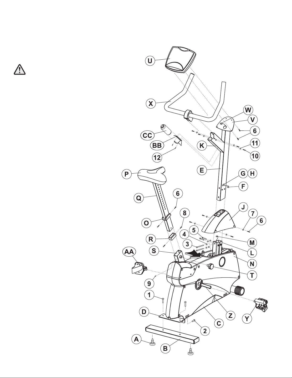
ASSEMBLING THE UPRIGHT EXERCISE BIKE
Tools Required: Metric Wrench Set, Metric Allen
Wrench Set, Phillips Screwdriver
1. Locate and install the two LEVELER FEET (A) to the
bottom of the REAR STABILIZER (B).
2. Attach the REAR STABILIZER (B) to the BASE UNIT
(C) using two 2-3/8" BUTTON HEAD SCREWS (1)
from the top of the REAR STABILIZER BRACKET (D)
and two 13/16" BUTTON HEAD SCREWS (2) from the
front side of the REAR STABILIZER BRACKET.
Tighten the SCREWS securely.
3. Locate the MONOCOLUMN (E). Insert the WIRE (F)
leading from the SIDE ACCESS HOLE (G) of the
MONOCOLUMN fully into the MONOCOLUMN.
Remove the GROMMET (H) from the SIDE ACCESS
HOLE and set it aside.
4. Slide the MONOCOLUMN COVER (J) onto the
MONOCOLUMN (E) as shown. Slide the MONOCOL-
UMN COVER up to the HANDLEBAR TUBE (K).
5. Re-insert the GROMMET (H) into the SIDE ACCESS
HOLE (G) of the MONOCOLUMN (E). Pull the WIRE
(F) back out through the SIDE ACCESS HOLE.
6. With the HANDLEBAR TUBE (K) facing the rear of the
unit as shown, slide the MONOCOLUMN (E) into the
MONOCOLUMN BRACKET (L) of the BASE UNIT (C).
Slide the MONOCOLUMN down until it is fully seated.
Secure the MONOCOLUMN to the MONOCOLUMN
BRACKET using two 3-15/16" HEX HEAD BOLTS (3)
and three LOCK WASHERS (4) (as shown) from the
rear side of the MONOCOLUMN and two 2-3/8" HEX
HEAD BOLTS (5) and LOCK WASHERS (4) from the
user left side of the MONOCOLUMN BRACKET.
Tighten the BOLTS securely.
CAUTION: BE CAREFUL NOT TO PINCH THE
WIRE (M) LEADING FROM THE MONOCOLUMN
BRACKET (L) WHEN INSERTING THE MONO-
COLUMN (E) INTO THE MONOCOLUMN
BRACKET.
7. Connect the WIRE (M) leading from the MONOCOL-
UMN BRACKET (L) to the corresponding WIRE (F)
from the SIDE ACCESS HOLE (G) of the MONOCOL-
UMN (E). Slide the MONOCOLUMN COVER (J)
downward to the meet the MAIN SHROUDS (N).
Secure the MONOCOLUMN COVER to the MAIN
SHROUDS using four 1/2" PHILLIPS SCREWS (6)
and matching FLAT WASHERS (7). Tighten the
SCREWS securely. Do not overtighten the SCREWS.
8. Locate the SEAT POST CAP (O). With the curved side
facing upward toward the SEAT (P), slide the SEAT
POST CAP over the SEAT POST (Q).
9. Locate and slide the SEAT POST SPACER (R) over
the end of the SEAT POST (Q). Using two 1/4"
PHILLIPS SCREWS (8), secure the SEAT POST
SPACER to the end of the SEAT POST. Tighten the
SCREWS securely.
10. With the nose of the SEAT (P) facing forward, insert
the SEAT POST (Q) into the SEAT POST SUPPORT
(S).
11. Begin inserting the SEAT ADJUSTMENT KNOB (T).
Lift upward on the seat and seat post until the seat
post locks into a position. Insert the 5/16" PHILLIPS
LOCKING SCREW (9) and tighten securely.
12. Slide the SEAT POST CAP (O) downward to meet the
top of the SEAT POST SUPPORT (S). Secure the
SEAT POST CAP to the SEAT POST SUPPORT using
two 1/2" PHILLIPS SCREWS (6). Tighten the
SCREWS securely. Do not overtighten the SCREWS.
13. Remove the DISPLAY CONSOLE (U) from its shipping
carton. Position the above the DISPLAY CONSOLE
BRACKET (V). Connect the CONNECTOR (W) lead-
ing from the DISPLAY CONSOLE BRACKET to the
corresponding jack located on the back of the DIS-
PLAY CONSOLE. Secure the DISPLAY CONSOLE to
the DISPLAY CONSOLE BRACKET using four 1/2"
PHILLIPS SCREWS (6). Tighten the SCREWS
securely. Do not overtighten the SCREWS.
14. Locate the HANDLEBAR ASSEMBLY (X). With the
handlebars facing forward, position the HANDLEBAR
ASSEMBLY near the top of the HANDLEBAR TUBE
(K). Slide the HANDLEBAR ASSEMBLY fully into the
HANDLEBAR TUBE. Secure the HANDLEBAR
ASSEMBLY to the HANDLEBAR TUBE using four 5/8"
BUTTON HEAD SCREWS (10) and matching FLAT
WASHERS (11). Tighten the SCREWS securely.
15. Locate the PEDALS. Install the RIGHT PEDAL (Y)
(marked with an "R") to the USER RIGHT CRANK
ARM (Z). Repeat for the LEFT PEDAL (AA) (marked
with an "L").
NOTE: THE LEFT PEDAL (Y) HAS REVERSE
THREADS.
16. Locate the WATER BOTTLE BRACKET (BB). Secure
the WATER BOTTLE BRACKET to the underside of
the HANDLEBAR TUBE (K) using two 3/8" PHILLIPS
SCREWS (12). Tighten the screws securely. Insert the
WATER BOTTLE (CC) into the WATER BOTTLE
BRACKET.
17. Position the unit in the desired location for use. The
unit can be easily moved into place by lifting the rear
of the unit and rolling it on the front rollers. Level the
unit before use. Refer to the leveling instructions stat-
ed in the operations portion of this manual.
5
6
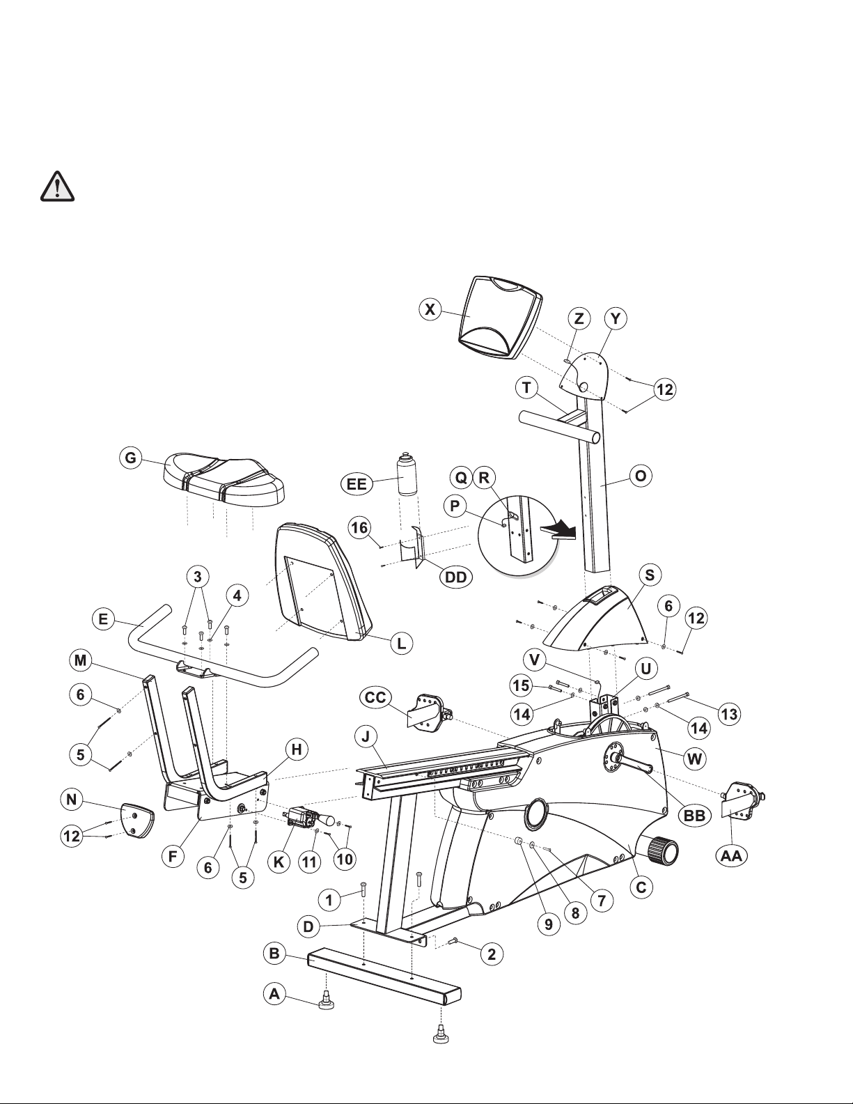
UNPACKING THE RECUMBENT EXERCISE BIKE
1. Carefully cut and remove the SHIPPING BANDS.
2. Carefully cut the tape securing the TOP FLAPS.
3. Fold the TOP FLAPS outward fully.
4. With the help of another person, remove the SIDE SHIPPING TRAY.
CAUTION: BE SURE TO KEEP THE LEFT AND RIGHT SIDES OF THE SIDE SHIPPING TRAY TOGETHER
WHILE REMOVING IT FROM THE SHIPPING CARTON.
5. Remove the DISPLAY CONSOLE carton and the ACCESSORY TRAY from beside the BASE UNIT.
6. With the help of another person, lift the BASE UNIT from the SHIPPING CARTON. Remove the protective packaging
from the unit.
 Loading...