


TR97
Model 97Te, 95Te, 97Ti, 95Ti, and 93T
ARCTIC SILVER Treadmills
Customer Support Services
SERVICE MANUAL
Life Fitness Model 97Te, 95Te, 97Ti, 95Ti and 93T Arctic Silver Treadmills
GENERAL CONTENTS
INTRODUCTION ...............................................................................................................ii
THEORY OF OPERATION ...............................................................................................iii
SPECIAL SERVICE TOOLS .............................................................................................iv
GLOSSARY ......................................................................................................................v
SECTIONAL CONTENTS
TROUBLESHOOTING 1
DIAGNOSTICS LED 2A
DIAGNOSTICS LCD 2B
HOW TO…SERVICE 3
ELECTRONICS 4
MISCELLANEOUS
5
i

Life Fitness Model 97Te, 95Te, 97Ti, 95Ti and 93T Arctic Silver Treadmills
Introduction
This Service Manual provides safe and efficient step-by-step test and service procedures for 97Ti, 97Te,
95Ti, 95Te, and 93T Treadmills. The “Ti” designation stands for Light Emitting Diode (LED) Consoles
and the “Te” designation stands for Liquid Crystal Display (LCD) Consoles. Illustrations in this manual
reflect service view(s) to compliment the step-by-step procedure. Unnecessary views or details may not
be illustrated for the sake of clarity.
When a service problem occurs, it is recommended that you first refer to “Troubleshooting” in Section 1
or “Diagnostics” in Section 2. Refer to “How To…” in Section 3 for actual service procedures, and in
addition, Special Service Tools will be listed otherwise, standard tools should be used. Refer to
“Electronics” in Section 4 for Block Diagrams and Connector locations. Refer to “Miscellaneous” in
Section 5 for ID Tag Location, Maintenance, and other general information pertinent to the product.
Life Fitness Customer Support Services (CSS) can be contacted Monday - Friday 8:00 AM - 5:00 PM
Central Standard Time. To response to your needs expeditiously, please provide Life Fitness Customer
Support Services with the following information:
• Model number
• Serial number
• Part name and number
• Problem or symptom
LIFE FITNESS – CUSTOMER SUPPORT SERVICES
10601 Belmont Avenue; Franklin Park, IL 60131; U.S.A.
Telephone: 847.451.0036 Toll-free: 800.351.3737
FAX: 847.288.3702 Toll-free: 800.216.8893
ii

Life Fitness Model 97Te, 95Te, 97Ti, 95Ti and 93T Arctic Silver Treadmills
Theory of Operation
The Treadmill is an electromechanical device that operates on A/C Voltage System and is controlled
through the electronics in the Display Console. The key components that make up the Treadmill are the
Unit Frame, Electric Motor and Motor Controller, Belt and Deck, Pulleys and Rollers, and the Display
Console.
Initially the Line Filter receives the voltage. It is to the Motor Controller and other various electrical and
electronic components that activate all the mechanical devices. The operator ultimately controls all
electromechanical devices through the Console Display and with a touch of a finger can make settings
and adjustments to Speed, Incline, and Custom Workout Programs.
The Unit Frame is critical not only to support the operator but also to support the electromechanical
devices and the unit’s overall appearance. Although the frame is a non-maintenance item, its design and
structure are essential to providing years of safe and reliable service.
The most critical parts on the Treadmill are the Striding Belt and Deck. Regardless of all other
components, the success of a good Treadmill is its Striding Belt and Deck. The Deck is made up of a
special particleboard, which allows for flexibility and long wear. The Waxless Striding Belt allows for self
lubrication to ensure long life to both belt and deck. Under the Deck are the Lifesprings™, which are
designed to support and absorb the shock load.
The Striding Belt is designed to endure constant stress loads. It is mounted directly over the Front and
Rear Rollers. The Main Drive Motor has a Pulley on the end of its shaft, which is connected by a Drive
Belt to the Front Roller Pulley. The Rear Roller is freewheeling. The Striding Belt tension is adjustable by
means of Adjusting Bolts, which are located at the ends of the Rear Roller. When turned, they are used
to adjust belt tension and belt centering. In order to increase belt and deck life, it is important to properly
keep all areas of the machine clean.
The Display Console is the brain center of the Treadmill. It is here where all electromechanical
operations are controlled for specific program operations. Depending on the Display Console, various
selections and settings can be easily accomplished either through a Numeric Keypad or Up/Down
Arrows. The Display Console allows the operator to selectively choose the program and input pertinent
statistical information such as Weight, Age, Language, etc.
The Treadmill is by far one of the most popular pieces of all cardiovascular exercise equipment. With
proper routine preventative maintenance and care, it will provide a lifetime of healthy cardiovascular
exercise.
iii

Life Fitness Model 97Te, 95Te, 97Ti, 95Ti and 93T Arctic Silver Treadmills
Service Tools
Unless otherwise specified, only basic hand tools are required to perform service procedures outlined in
the How To... section of this manual, which consist of:
• Philips and Straight-Blade Screw Drivers
• TORX
• Pliers
• Rubber Mallet
• Snap Ring Pliers (internal and external)
• Removable Thread Locking Compound
• Standard and Metric Size Socket Set (3/8" or 1/2" drive)
• Standard and Metric Size Combination, open-end, or Box Wrenches
®
Bit Set
iv

Life Fitness Model 97Te, 95Te, 97Ti, 95Ti and 93T Arctic Silver Treadmills
GLOSSARY
Familiarize yourself with those words and acronyms commonly referred to in this manual.
Anti-Scuff Pads
Connectors
Deck
Display Console
Board
EEPROM
EEROM
Frame Tag
Board
Front Roller
HR Sensor
Idler Pulley
Assembly
Rubber strips located on the surface of each side of the frame, and used to ensure
sure footing.
Plastic devices used to connect wiring together.
Special particleboard that is used for the running surface.
Electronic board used for making direct input settings and monitoring output
messages, which are displayed in the digital readout display.
Electrically erasable programmable read only memory.
Electrically erasable read only memory.
Stores maintenance and error data with date and time stamp.
Motor belt driven, the front roller drives the striding belt.
Located in each handle grip and measures heart rate.
A spring-loaded bracket assembly pulley, which is used to maintain constant load
against the main drive belt.
Jumper
LED
LCD
Levelers
Lift Motor
LifePulse
LifeSprings
Electrical connector used to connect between two electrical points.
Light Emitting Diodes.
Liquid Crystal Display
Adjustable supports under the rear of the treadmill, which are used to stabilize the
unit.
The motor that raises and lowers the unit for incline and decline operations.
Measures heart rate.
Springs under the deck to absorb impact of the walker or runner.
v

Life Fitness Model 97Te, 95Te, 97Ti, 95Ti and 93T Arctic Silver Treadmills
GLOSSARY
Main Drive Belt
Connects between the main drive motor pulley and the front roller pulley, and used
to transmit the driving power of the main drive motor to the front roller.
Main Wire
Harness
Motor Controller
Overlay Bezel
PCB
Power Module
Polar Receiver
Smart Stop
Sensor
Rear Roller
Rear Roller
Guards
RPM
Static Current
Stop Switch
Striding Belt
Connected to the operating components of the unit to provide electrical power.
Regulates the speed of the striding belt.
A clear plastic covering over the display console.
Programmable Circuit Board
Receives main electrical source from the wall outlet to distribute voltage throughout
the various electromechanical systems.
Monitors heart rate.
Senses the presence of an operator.
A free spinning roller with adjusting screws at each end of the roller used for
tensioning and centering the striding belt.
Located at the back of each side of the rear roller, are used as protective guards.
Revolutions per minute.
Steady current flow.
A switch used to interrupt power going to the motor to stop the unit.
Sometimes referred to as the 'walking belt' and used to walk or run on.
Telemetry
Receiver
Ties
Wax/Lift Board
A sensor that reads Heart Rate signal from the operator's chest strap transmitter.
Plastic straps used to secure loose wiring to the main frame.
A circuit board, which is located under the motor shroud, is used to communicate
input/output signals to and from the console, wax and lift motors, frame tag, and
motor.
vi

Life Fitness Model 97Te, 95Te, 97Ti, 95Ti and 93T Arctic Silver Treadmills
Contents
SECTION 1
TROUBLESHOOTING GUIDE
Page
No Power To Treadmill..............................................................................................................................3
No Power To Treadmill Console................................................................................................................5
No Power ...................................................................................................................................................6
Display Does Not Illuminate.......................................................................................................................6
Striding Belt Slips During Footfall ..............................................................................................................6
Maximum Speed Is Reduced.....................................................................................................................6
Knocking Sound At Rear Of Machine ........................................................................................................6
Knocking Sound Coming From Deck.........................................................................................................6
Rubbing Sound From Underneath Machine ..............................................................................................7
Display Reads Immobilized .......................................................................................................................7
Squeaking Noise........................................................................................................................................7
Loud Groaning Sound From Front Of Machine .........................................................................................7
Loud Groaning Sound On Footfall.............................................................................................................7
Display Overlay Keys Are Not Responding When Pressed....................................................................... 7
Unit Resets Randomly Or Pauses .............................................................................................................7
Striding Belt Is Traveling Beyond Tracking Limits .....................................................................................8
Striding Belt Not Centered .........................................................................................................................9
Striding Belt Misalignment .........................................................................................................................9
LifePulse Heart Rate Does Not Respond ..................................................................................................9
Display Reads Heart Rate With Hands Removed .....................................................................................9
No Chest Strap Detected...........................................................................................................................9
Erratic Heart Rate Readings......................................................................................................................10
Abnormally Elevated Heart Rate Readings ...............................................................................................10
Motor Controller Comm Bad: Check Harness Between Lift
And Controller –P9/P3 ........................................................................................................................10
Motor Controller Comm Bad: Check Power To Motor Controller............................................................... 10
Wax And Lift Board Comm Bad: Check Power On Lift..............................................................................10
Both Lift And Controller Comm Bad: Check Harness Between
Console And Lift –P1 And P1 .............................................................................................................11
System Configured Two Wired ..................................................................................................................11
Incline Inoperative......................................................................................................................................11
Home Switch Error.....................................................................................................................................11
Negative Switch Error ................................................................................................................................11
Smart Stop Unplugged ..............................................................................................................................12
Clock Comm Bad.......................................................................................................................................12
Frame Tag Unplugged...............................................................................................................................12
Sci Error.....................................................................................................................................................12
Dynamic Current Trip.................................................................................................................................12
Checksum Error Xxxx ................................................................................................................................12
Notify Maintenance Motor Controller Error ................................................................................................12
Notify Maintenance Incline Timeout Error..................................................................................................13
Notify Maintenance Home Switch Error.....................................................................................................13
1-1

Life Fitness Model 97Te, 95Te, 97Ti, 95Ti and 93T Arctic Silver Treadmills
Contents (continued)
Page
Notify Maintenance Negative Switch Error ................................................................................................13
Notify Maintenance Frame Tag Unplugged ...............................................................................................13
Unable To Attain Target Speed .................................................................................................................13
Notify Maintenance Speed Sensor Error ...................................................................................................13
External Rom Failure .................................................................................................................................13
Channels or Volume Does Not Change.....................................................................................................14
No Volume For TV Reception....................................................................................................................14
Unable To Receive Channels ....................................................................................................................14
Snow And Noise ........................................................................................................................................14
Screen Is Blank..........................................................................................................................................14
Wrong Buttons Activate ............................................................................................................................14
TV Receives Channels 5 & 6 Only ............................................................................................................14
Screen Does Not Turn On and No Sound .................................................................................................15
No Beeps ...................................................................................................................................................15
Only One Beep ..........................................................................................................................................15
Only One Beep At Power Up .....................................................................................................................15
One Beep Followed By Three Beeps ........................................................................................................15
Only One Beep ..........................................................................................................................................15
One Beep And A Burp ...............................................................................................................................15
One Beep And Three Beeps......................................................................................................................15
Channels Do Not Change..........................................................................................................................16
Sound Does Not Change...........................................................................................................................16
No TV Sound .............................................................................................................................................16
Unable To Receive TV Channels ..............................................................................................................16
Snow And Noise ........................................................................................................................................16
Screen Is Blank..........................................................................................................................................16
Screen Is Dark ...........................................................................................................................................16
Screen Does Not Respond To Touch........................................................................................................16
The Wrong Buttons Activate ......................................................................................................................16
Screen Does Not Turn On and No Sound .................................................................................................16
Console Does Not Light Up .......................................................................................................................16
No Audio From FM Radio ..........................................................................................................................17
Audio Static From FM Radio......................................................................................................................17
Snowy Appearance When Viewing Secure Screen...................................................................................17
No Channel Select.....................................................................................................................................17
Notes` ........................................................................................................................................................18
1-2
Life Fitness Model 97Te, 95Te, 97Ti, 95Ti and 93T Arctic Silver Treadmills
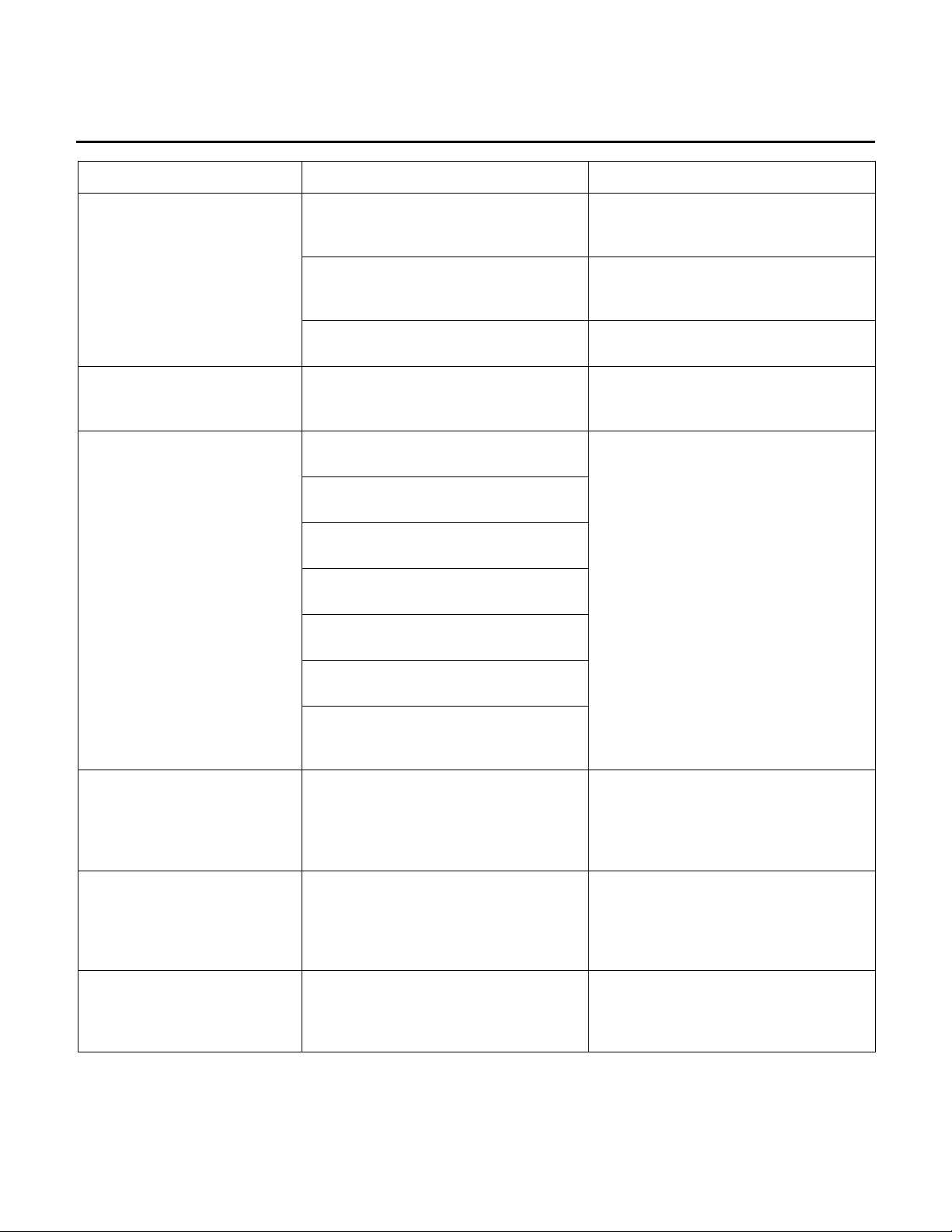
TROUBLESHOOTING GUIDE
NO POWER TO TREADMILL
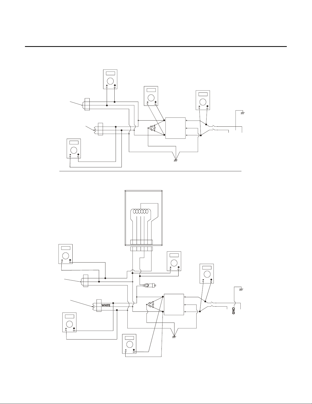
In order to diagnose NO POWER to Treadmill, the Motor Cover must be removed, and the Treadmill must be
plugged into an electrical outlet. Use the following TROUBLESHOOTING CHART to take the proper corrective
action for NO POWER TO TREADMILL. In conjunction with this Chart, refer to the next page to reference Test
Points (TP1 through TP5) on the Electrical Schematic.
STEPS INSPECT ACTION RESULTS
If Line Voltage is present, then continue on to Step 2. 1 Line Cord Voltage Remove the Line Cord Bracket, unplug
the Line Cord from Treadmill, and then
test for Line Voltage.
for Line Voltage at TP1.
for Line Voltage at TP2.
for Line Voltage at TP3.
5 Motor Controller Turn the Unit Power Switch ON, and test
for Line Voltage at the Motor Controller
Cable at TP5.
6 Auto Transformer
and Wax/Lift
Board
Turn the Unit Power Switch ON, and test
for 120v AC at the Wax/Lift Board Cable
at TP4.
NO LEDs are lit on the Wax/Lift Board. Remove the Wax/Lift Board from the Treadmill.
Fuse No. 1 is open.
Fuses No. 2 or 3 are open. Check for a shorted wire at the Lift Motor. The
If Line Voltage is not present, then test for Voltage at
wall outlet. If no voltage is present, then check the
Main Service Breaker at the Facility. If wall outlet
voltage is present, then replace the Line Cord.
If Line Voltage is present, then continue on to Step 3. 2 Power Switch Turn the Unit Power Switch ON, and test
If Line Voltage is not present, then replace Power
Switch.
If Line Voltage is present, then continue on to Step 4. 3 Line Filter Turn the Unit Power Switch ON, and test
If Line Voltage is not present, then replace the Line
Filter.
If Line Voltage is present, then continue on to Step 5. 4 Circuit Breaker Turn the Unit Power Switch ON, and test
If the Line Voltage is not present, then reset the
Circuit Breaker, or if necessary replace it.
If Line Voltage is present and NO LEDs are lit then
check to see if the Motor Cable is unplugged or
damaged, and replace as necessary.
If Line Voltage is present and NO LEDs are lit, then
check to see if the Motor is overheated or is
damaged. With the Motor unplugged, OHM out the
two blue wires using a Multi-Meter. If there is NO
Continuity, then replace Motor. If NO Line Voltage
present, then check Cables between the Power Box
and Motor Controller, and replace as necessary.
Check for damaged cables and replace. If the cables
are not damaged, replace the Auto Transformer.
Check fuses 1, 2, and 3, with the Multi-Meter set on
resistance. If the fuses are good, then test the power
cable from the Power Box to the Wax/Lift Board for
120 Volts. If fuses are open, then replace the Wax/Lift
PCB.
Inspect the Wax/Lift Board for any signs of damage.
If damaged, replace the Wax/Lift Board.
Inspect cabling from the Wax/Lift Board to: Frame
Tag, Motor Controller, Negative Switch, and Lift Motor
Home Switch. If cabling is damaged, then replace as
necessary.
resistance is checked at the: Black to Red wire, which
should read about 30 OHMS; the White to Red wire
should read 15 OHMS, and the White to Black wire
should also read 15 OHMS. If any of these wires
register ‘0 OHMS’, then replace the Lift Motor.
is
1-3
Life Fitness Model 97Te, 95Te, 97Ti, 95Ti and 93T Arctic Silver Treadmills
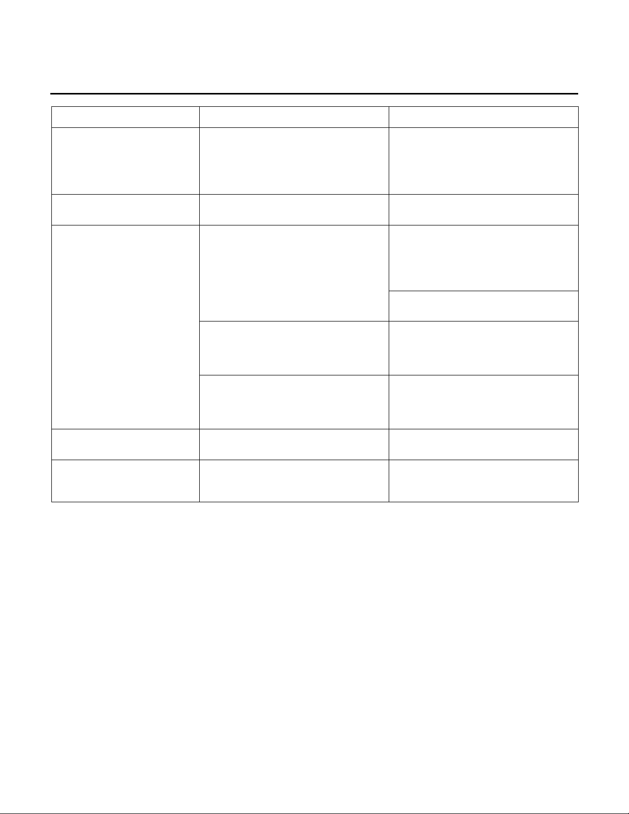
TROUBLESHOOTING GUIDE
NO POWER TO TREADMILL - Continued
Multi Meter
TP4
BLACK
Wax/Lift
Power
1
2
3
WHITE
GREEN
120V DOMESTIC
Settings AC
TP2
Multi Meter
Settings AC
TP1
Multi Meter
Settings AC
#GRN/YLW
Motor Controller
Power
Multi Meter
TP5
Multi Meter
Settings AC
TP4
Settings AC
#BLACK
1
2
#WHITE
3
#GREEN
220/230V CABLE SHOWN
AUTO X-FRMR
200V IN
COM
100V IN
220/230V IN
1 2 3 4 5 6
1 2 3 4 5 6
LINE
BLK
GRN/YLW
WHT
#BLK
#WHT
NEU
GND
HOT
LL
MOV
LOAD
NN
LINE FILTER
ON/OFF Switch
100V, 200-240V FOREIGN
120V OUT
240V IN
T3P
Multi Meter
Settings AC
Multi Meter
Settings AC
Wax/Lift
Power
Motor Controller
Power
Multi Meter
TP5
Settings AC
1
2
3
BLACK
WHITE
GREEN
1
2
3
BLACK
GREEN
T2P
Multi Meter
Settings AC
Circuit Breaker
L
MOV
LOAD
N
LINE FILTER
1-4
L
LINE
N
BLK
GRN/YLW
WHT
T1P
GRN/YLW
BLK
WHT
NEU
ON/OFF Switch
HOT
Life Fitness Model 97Te, 95Te, 97Ti, 95Ti and 93T Arctic Silver Treadmills
TROUBLESHOOTING GUIDE
NO POWER TO TREADMILL CONSOLE
Use the following procedure to troubleshoot No Power to the Treadmill Console.
1. Turn the Power OFF to the Unit.
2. Remove the Console Assembly to gain access to the Main Wiring Harness (P1). Leave all cables connected
for testing.
3. Turn the Power back ON.
4. Place the BLACK Negative lead of the Multi-Meter on Pins No. 1 (yellow) and 2 (orange) to obtain a ground.
5. Place the RED Positive lead of the Multi-Meter on the corresponding wire to the verify voltage.
6. Following the Troubleshooting Chart below to verify problem.
TROUBLESHOOTING – “NO POWER TO DISPLAY CONSOLE”
VOLTS FUSE
NO.
12VDC 4 White Short circuit in the Emergency
8VDC
8VDC
6 Red Short circuit in the Console
5 Brown
WAX/LIFT
BOARD WIRE
POSSIBLE CAUSE SOLUTION
Stop Switch Circuit.
PCB.
Short circuit in the Console
PCB.
Short in the Smart Stop Circuit
or Cable.
C-SAFE Port, Fuse No. 5,
shorts out when plugging in an
accessory.
If Voltage is present and the Console is not
ON, then replace the Console PCB.
If NO Voltage is present, then check the
corresponding Wax Lift Board Fuse.
If Voltage is present and the Console is not
ON, then replace the Console PCB.
If NO Voltage is present, then check the
corresponding Wax Lift Board Fuse.
If Voltage is present and the Console is not
ON, then replace the Console PCB.
If NO Voltage is present, then check the
corresponding Wax Lift Board Fuse.
Inspect the Smart Stop Circuit Board and
Cables for damage. If necessary, replace.
Unplug the accessory that is connected to
the C-SAFE ports. If problem continues
with the accessory unplugged, replace the
Console. If problem only persists with
accessory plugged in, then the accessory
vendor must be contacted.
Check for shorts in cables. If necessary, replace.
1-5
Life Fitness Model 97Te, 95Te, 97Ti, 95Ti and 93T Arctic Silver Treadmills
TROUBLESHOOTING GUIDE
SYMPTOM PROBABLE CAUSE CORRECTIVE ACTION
No Power.
Display does not illuminate
when machine is powered
on.
Striding Belt slips during
footfall.
Insufficient power source. Plug treadmill into a proper electrical
configuration. Refer to the Operations
Manual.
Circuit breaker, if equipped. Verify that circuit breaker is not open. If
open, reset circuit breaker, if equipped.
Insufficient power source. Plug treadmill into a proper electrical
configuration. Refer To The
Operations Manual.
Loose 10-pin connection at display
console or wax/lift control board.
Damaged main harness wire
connection.
Row of six LEDs not lit. Check that the EEPROM in the Wax
Wax/Lift Board EEPROM not seated or
missing.
Striding belt slips on front roller during
stall test.
Check all electrical connections for
proper attachment.
Replace wire harness. See How
To…Replace Main Wire Harness.
Lift Board is seated properly. If
necessary replace the Wax Lift Board.
If row of 6 LEDs not lit on top of
Wax/Lift Board, then check that the
EEPROM in the Wax/Lift Board is
seated properly. Replace the Wax/Lift
Board if necessary.
Check striding belt & re-tension as
necessary. See How…To Adjust Belt
Tension.
Maximum speed is
reduced.
Knocking sound at rear of
machine.
Knocking sound coming
from deck.
User is pushing striding belt. Instruct users not to push striding belt
in either direction.
Striding belt/deck malfunction. The
deck laminate worn through or the
underside of striding belt glazed over
(hard, glossy).
Insufficient power source. Plug treadmill into a proper electrical
Faulty rear roller bearings. Replace rear roller assembly.
Life Springs not positioned correctly
and/or loose mounting hardware.
Replace belt and deck. See How
To…Replace Striding Belt.
configuration. Refer to the Operations
Manual.
Reposition or tighten life springs.
1-6
Life Fitness Model 97Te, 95Te, 97Ti, 95Ti and 93T Arctic Silver Treadmills
TROUBLESHOOTING GUIDE
SYMPTOM PROBABLE CAUSE CORRECTIVE ACTION
Rubbing sound from
underneath machine.
Display reads immobilized.
Squeaking noise.
Loud groaning sound heard
from front of machine while
elevating.
Loud groaning on footfall.
Display overlay keys are
not responding when
depressed.
Foreign objects may be stuck
underneath the machine.
Immobilized feature is activated. Press and hold the SPEED Down
Drive Motor Belt tensioning pin may be
squeaking.
Drive Motor Belt may be worn or
damaged.
Lift mechanism pivot points are dry. Clean and lubricate as necessary.
Faulty lift motor. Replace the lift motor. See How
Obstruction. Inspect wheels or flooring for damage.
High friction between deck and striding
belt.
Loose ribbon connection(s). Test the Key Pad function. See
Inspect underneath striding belt and
machine. Remove any debris or
objects that may cause interference
with the treadmill.
Arrow Key and press the Pause Key to
toggle ON/OFF.
Clean and lubricate as necessary.
Replace Drive Motor Belt. See How
To… Replace Drive Motor Belt.
To…Replace Lift Motor.
Refer to Belt and Deck Test in
Diagnostics.
Diagnostics in this Section. Verify that
the two ribbon connections are
attached to the display PCB. Test Key
Pad function.
Unit resets randomly or
pauses.
If attached, reseat the connection and
verify the operation.
Worn or defective overlay assembly. Replace overlay assembly. See How
To… Replace Overlay Assembly.
Insufficient power source. Plug treadmill into a proper electrical
configuration. Refer to the Operations
Manual.
Damaged ground prong on line cord. Replace line cord. See How To…
Replace Line Cord.
Line cord improperly seated in
electrical outlet.
Emergency stop magnet not engaged. Re-engage the emergency stop
Towel or magazine may be making
contact with stop switch while user is
running.
Loose connections at display console. Secure all connections at display
Inspect power connection at electrical
outlet and at machine for proper
contact.
magnet.
Move all possible obstructions off
display console and handlebar.
console PCB.
1-7

Life Fitness Model 97Te, 95Te, 97Ti, 95Ti and 93T Arctic Silver Treadmills
TROUBLESHOOTING GUIDE
SYMPTOM PROBABLE CAUSE CORRECTIVE ACTION
Unit resets randomly or
pauses.
The Striding Belt is
traveling beyond the
tracking limits.
Stop Switch is activated with very light
pressure or returns very slowly after
being pressed.
Stop switch cable not making proper
contact.
Pinched main wire harness. Replace the main wire harness. See
Open ground path. Using voltmeter, check all points for
Inspect Smart Stop system. Disconnect the 4-pin connector and
Striding belt needs to be re-tensioned
or tracking needs adjustment.
Unit is not level. Refer to the Operation Manual or
Replace Stop Switch. See How
To…Replace Stop Switch.
Re-seat cable from stop switch and
verify the operation.
How To…Replace Main Wire Harness.
continuity: console pan screws,
console mounting screws, handlebar
screws, and handrail mounting screws
to frame with respect to ground.
Ground must be a non-painted
surface.
verify if problem exists. If no, replace
Smart Stop PCB. See “How To…”
Replace Smart Stop PCB.
Refer to belt tensioning or tracking
adjustment procedure in operation or
service manual.
Service Manual.
Check to see if the belt barriers are still
in place or damaged.
Contact Life Fitness
1-8
Life Fitness Model 97Te, 95Te, 97Ti, 95Ti and 93T Arctic Silver Treadmills
TROUBLESHOOTING GUIDE
SYMPTOM PROBABLE CAUSE CORRECTIVE ACTION
Striding belt not centered.
Striding belt misalignment,
but properly tensioned.
Lifepulse Heart Rate
System does not respond
or improper heart rate
reading or "Reading Heart
Rate" appears in the
message center for more
than 2 minutes without
giving heart rate reading.
Display reads a continuous
heart rate reading when
hands are removed.
Striding belt tension or tracking needs
to be adjusted.
Improper walking/running. Notify Club Manager.
Dirty handlebar sensors. Wipe sensors with a clean soft cloth.
User running over 4.5 mph (7.5kph). For accurate heart rate reading, user
User may have an unusual heart
condition.
Loose connections at display console
and handlebar.
Faulty heart rate sensors. Replace handlebar sensors. See How
Faulty display console PCB. Replace display console PCB. See
Harness wires pinched at handlebar or
handrail.
See How To…Adjust And Tension The
Striding Belt.
Verify operation. Refer to Diagnostics
in Section 2.
must slow down to less than 4.5 mph
(7.5kph).
Have different people grasp sensors to
detect any variance.
Secure connections at display console
and handlebar.
To… Replace Heart Rate Kit.
How To… Replace Console PCB.
If the wires are damaged, replace
damaged cables. See How
To…Replace Handlebar Assembly.
No Chest Strap detected.
Chest strap sensors not making good
contact with body of user.
User is out of monitoring range. Move within 3 ft (1 meter) of receiver
Loose connection at receiver. Check connection. See “How
Faulty chest strap. Replace chest strap.
Adjust chest strap and moisten
sensors to make better contact with
skin.
To”...Replace Telemetry Receiver.
1-9
Life Fitness Model 97Te, 95Te, 97Ti, 95Ti and 93T Arctic Silver Treadmills
TROUBLESHOOTING GUIDE
SYMPTOM PROBABLE CAUSE CORRECTIVE ACTION
No Chest Strap Detected
Erratic Heart Rate readings.
Abnormally elevated heart
rate readings.
Faulty receiver. Verify 5VDC at P6 pin 1. If yes, replace
transmitter. If no, replace display
console PCB.
Telemetry turned OFF. Enter Manager’s Configuration in the
Diagnostic mode, and then turn
telemetry to ON.
Bad connection at Telemetry cable
and receiver.
Treadmills are located less than 8”
(203 mm) apart.
Electromagnetic interference from
television sets and /or antennas.
Electromagnetic interference from cell
phones.
Electromagnetic interference from
computers.
Electromagnetic interference from
cars.
Electromagnetic interference from high
voltage power lines.
Check cable jack and receiver
connection.
Position treadmills to recommended
distances. Refer to the Operations
Manual.
Move the treadmill a few inches away
from the probable cause, or move the
probable cause a few inches away
from the treadmill, until the heart rate
readings are accurate.
Display Reads: MOTOR
CONTROLLER COMM BAD:
CHECK HARNESS
BETWEEN LIFT &
CONTROLLER -P9/P3
Display Reads: MOTOR
CONTROLLER COMM BAD:
CHECK POWER TO MOTOR
CONTROLLER.
Display Reads: WAX/LIFT
BOARD COMM BAD:
CHECK POWER ON LIFT
Electromagnetic interference from
motor driven exercise equipment.
Electromagnetic interference from
another heart rate transmitter within 3
ft (1m).
Loose wire harness. Reset connections at wax/lift PCB
connector P9 and motor controller
PCB connector P3.
Bad Motor Controller. Verify line voltage at P1 on the Motor
Controller. If voltage exists, replace
motor controller. See “How To…”
Replace Motor Controller. Refer to
Section 4 Voltage Specifications.
Bad Wax/Lift PCB. Verify if the LED 7 (Green) and LED 8
(Red) is lit on the Wax/Lift PCB. If no,
replace Wax/Lift PCB. See How To
Replace…Wax /Lift PCB.
1-10
Life Fitness Model 97Te, 95Te, 97Ti, 95Ti and 93T Arctic Silver Treadmills
TROUBLESHOOTING GUIDE
SYMPTOM PROBABLE CAUSE CORRECTIVE ACTION
Display Reads: BOTH LIFT
and CONTROLLER COMM
BAD: CHECK HARNESS
BETWEEN CONSOLE &
LIFT -P1/P1
Display Reads: SYSTEM
CONFIGURED TWO WIRED
Display Reads: INCLINE
INOPERATIVE – CONTINUE
IF DESIRED
Loose wire harness. Reset connection at Wax/Lift PCB
connector P1 and Display Console
PCB connector P1.
Motor Controller is not jumped
correctly.
Level or negative switch.
Lift motor adjustment incorrect. See “How To…Replace the Lift Motor”
Lift Motor. Cycle motor in incline manual and
Reset jumper at JM1 on both pins.
Refer to the Diagnostics Section 2,
Incline Automatic to verify the
operation. If replacement is required.
See “How To…” Replace Leveler or
Negative Switch.
Inspect wire harness for damage, and
replace if needed.
and refer to the step in the procedure
that describes 13-3/4” tube
adjustment.
verify 120VAC at P7 on Wax/Lift PCB.
If not, replace lift motor. See How To
Replace…Lift Motor.
Display Reads: HOME
SWITCH ERROR
Display Reads: NEGATIVE
SWITCH ERROR
Lift switches wire harnesses are
backward (applies only to 97Ti).
Lift switches wire harnesses are
backward (applies only to 97Ti
decline).
Switch the wire harnesses on the
negative and level switches.
Switch the wire harnesses on the
negative and level switches.
1-11
Life Fitness Model 97Te, 95Te, 97Ti, 95Ti and 93T Arctic Silver Treadmills
TROUBLESHOOTING GUIDE
SYMPTOM PROBABLE CAUSE CORRECTIVE ACTION
Display Reads: SMART
STOP UNPLUGGED (95Ti
and 97Ti are equipped)
Display Reads: CLOCK
COMM BAD
Display Reads: FRAME
TAG UNPLUGGED
Display Reads: SCI ERROR
Display Reads: DYNAMIC
CURRENT TRIP
Display Reads: CHECKSUM
ERROR XXXX
Display Reads: NOTIFY
MAINTENANCE MOTOR
CONTROLLER COMM BAD
ERROR
Broken, damaged, or unplugged
harness.
Frame board or bad wire harness. See
Diagnostic Test Frame Tag EEPROM.
Disconnected wire harness. Reconnect wire harness.
Bad wire harness connection. Bad wire harness or noise. Reseat
Motor Controller, striding belt or deck. Perform belt and deck test in
Display Console Replace Display Console
Motor Controller. Overheated motor caused by worn or
Reseat or replace smart stop harness.
Verify continuity on wire harness. If
continuity exists, replace frame tag
PCB. See How To… Replace Frame
Tag PCB.
If continuity does not exist, replace
wire harness.
connection and verify operation. If
problem exists, reconnect your
connection at the display console to
wax/lift PCB
Diagnostic Section 2.
damaged belt and deck. See Belt and
Deck Test in Diagnostic Sect 2.
1-12
Life Fitness Model 97Te, 95Te, 97Ti, 95Ti and 93T Arctic Silver Treadmills
TROUBLESHOOTING GUIDE
SYMPTOM PROBABLE CAUSE CORRECTIVE ACTION
Display Reads: NOTIFY
MAINTENANCE INCLINE
TIMEOUT ERROR
Display Reads: NOTIFY
MAINTENANCE
HOME SWITCH ERROR
Display Reads: NOTIFY
MAINTENANCE NEGATIVE
SWITCH ERROR
Display Reads: NOTIFY
MAINTENANCE FRAME
TAG UNPLUGGED
Display Reads: UNABLE TO
OBTAIN TARGET SPEED
Lift Motor. Cycle motor in incline auto and verify
120VAC at P7 on Wax/Lift PCB.
Replace lift motor.
Level switch, negative switch or wire
harness is defective.
Lift switches wire harnesses are
backward. This applies only to 97Ti.
Lift switches wire harnesses are
backward. This applies only to 97Ti.
Broken, damaged or unplugged
harness.
Incorrect power requirements. Refer to the Operations Manual
Striding belt/deck malfunction. If the
deck laminate is worn through or the
underside of striding belt is glazed
over (hard, glossy).
In incline auto in diagnostics, verify the
operation of the switches. Replace
switches if defective. See How
To…Replace Switches.
Verify the wire for continuity, replace
wire harness if defective.
Switch the wire harnesses on the
negative and level switches.
Switch the wire harnesses on the
negative and level switches.
Re-seat the frame tag wire harness.
Perform belt and deck test in
Diagnostics Section 2.
Replace belt and deck. See How To…
Replace Striding Belt.
Display Reads: NOTIFY
MAINTENANCE SPEED
SENSOR ERROR
Display Reads: EXTERNAL
ROM FAILURE
Motor Controller. Replace motor controller.
Speed sensor or disconnected wire
harness.
Display PCB. Replace display PCB.
This error will appear after a workout,
but the unit will continue to function.
Enter diagnostics, Speed Manual, and
look for a RPM reading. If no reading
exists, check continuity on the wire
harness. No continuity, replace wire
harness. If continuity exists, replace
speed sensor.
1-13
Life Fitness Model 97Te, 95Te, 97Ti, 95Ti and 93T Arctic Silver Treadmills
TROUBLESHOOTING GUIDE
SYMPTOM PROBABLE CAUSE CORRECTIVE ACTION
Key Pad malfunction. Run Key pad test in diagnostics. TV Channels or volume does
not change.
Interface PC board defective. Replace Interface PC board.
No volume for TV Reception.
Unable to receive any
channels when using cable.
Snow and noise appear on
the screen.
Screen is blank or dark with
or without sound
Faulty headphones. Replace headphones.
Faulty headphone jack assembly. Replace headphone jack assembly.
Faulty cable to Headphone jack
assembly
Problem on the single board computer Replace single board computer.
Problem on Interface board Replace interface board
Air/cable setting may not be correct. Follow the setup procedures in the
Air/cable setting may not be correct. Follow the setup procedures in the
75 ohm coax may be bad. Replace 75 ohm coax.
75 ohm coax may be unplugged. Make sure cable is properly secure.
Air/cable setting may not be correct. Follow the setup procedures in the
75 ohm coax may be bad. Replace 75 ohm coax.
Back Light power inverter bad Replace/reconnect LCD/Touch Screen
LCD Back Light Replace/reconnect backlight inverter
LCD Screen failure Replace/reconnect LCD/Touch Screen
Replace cable to headphone jack
assembly.
operator manual.
operator manual.
operator manual.
The wrong buttons activate
when the touch screen is
touched.
TV receives channels 5 & 6
only.
Problem on the single board computer Replace single board computer.
Touch Screen not calibrated correctly
Cable selection standard. TV configuration correct setting
Calibrated Touch Screen in
diagnostics
Replace LCD/Touch Screen
1-14
Life Fitness Model 97Te, 95Te, 97Ti, 95Ti and 93T Arctic Silver Treadmills
TROUBLESHOOTING GUIDE
SYMPTOM PROBABLE CAUSE CORRECTIVE ACTION
Screen does not turn ON and
no sounds
No beeps are heard at power
up. After 15-20 seconds
console shows “System
Comm Unit time-out…..” error
message.
Only one beep is heard at
power-up. After 15-20
seconds a second beep.
One beep is heard at powerup followed by one burp
sound.
One beep is heard at powerup followed by 3 beeps. After
15-20 seconds another beep
is never heard and the screen
stays black.
No power.
Interface Board did not power up. Check Interface Board power cable.
Interface Board wasn’t able to
establish communications with all of
the treadmill modules. Console shows
error message of module that didn’t
respond.
Interface Board checksum error
detected. Console shows “System
Comm Unit time-out…” error message.
Console Board did not power up.
Interface Board has successfully
powered up and all treadmill modules
are responding properly.
Check Wax/lift board for 12 & 5 volts
DC and replace if faulty.
If Wax/Lift board ok check wire
harnesses and connectors.
Check power and cable coming from
Wax/Lift board.
Do a System Comm Test in
Diagnostics to get more information on
what modules are not working
properly.
Update Interface Board with the latest
software.
Check Console Board power cable.
One beep is heard at powerup followed by 3 beeps. After
15-20 seconds another beep
is heard but the screen stays
white.
One beep is heard at powerup followed by 3 beeps. After
15-20 seconds another beep
is heard but the screen stays
black.
Only one beep At power-up Interface board has power and is up
Only one beep and then one
burp
Only one beep followed by 3
beeps in a row
System is up and running but display
cable isn’t connected properly or is
faulty.
Display inverter isn’t working correctly. Check for disconnected or faulty
At power-up Interface board has power and has
At power-up Interface board is up and running and
Check display cable.
inverter cables.
and running
detected a checksum error. Unit will
not work
has successfully communicated with
all of the treadmill modules
1-15
Life Fitness Model 97Te, 95Te, 97Ti, 95Ti and 93T Arctic Silver Treadmills
TROUBLESHOOTING GUIDE
SYMPTOM PROBABLE CAUSE CORRECTIVE ACTION
TV Channels do not change.
TV Sound does not change.
No TV sound.
Unable to receive any TV
channels when using cable.
Snow and noise appear on
the screen.
Key pad malfunction. Run Key pad test in diagnostics.
Replace if defective.
Interface PC board defective. Replace Interface PC board.
Key pad malfunction. Run Key pad test in diagnostics.
Replace if defective.
Interface PC board defective. Replace Interface PC board.
Faulty headphones. Replace headphones.
Faulty headphone jack assembly. Replace headphone jack assembly.
Faulty cable to Headphone jack
assembly
Air/cable setting may not be correct Follow the set up procedures in the
Air/cable setting may not be correct. Follow the setup procedures in the
Coax Cable may be bad. Replace Coax Cable.
Coax Cable may be unplugged Reconnect Cable.
Air/cable setting may not be correct. Follow the setup procedures in the
Coax cable may be bad. Replace Coax cable.
Replace Headphone jack cable.
operator manual.
operator manual.
operator manual.
Screen is blank
touch.
when the touch screen is
touched.
Screen does not turn ON and
no sound.
there are audible Beeps
LCD Back Light burned up. Replace LCD/Touch Screen.
Back Light power inverter bad Replace backlight inverter
LCD Screen failure Replace LCD/Touch Screen.
Problem on the single board computer Replace Single Board Computer.
LCD Back Light burned up. Replace LCD/Touch Screen. Screen is dark.
Back Light power inverter bad Replace backlight inverter
Touch screen failure. Replace LCD/Touch Screen. Screen Does not respond to
Problem with Single Board Computer. Replace Single Board Computer.
Touch Screen not calibrated correctly Calibrate Touch Screen in Diagnostics.The wrong buttons activate
Touch Screen Damaged. Replace LCD/Touch Screen.
No power. Check Wax/lift board for 12 & 5 volts
DC and replace if faulty.
Faulty wire harness to console. Replace Wire Harness
Back light inverter defective. Replace inverter. Console does not Light up but
LCD defective. Replace LCD\TOUCH screen
1-16
Life Fitness Model 97Te, 95Te, 97Ti, 95Ti and 93T Arctic Silver Treadmills
TROUBLESHOOTING GUIDE
SYMPTOM PROBABLE CAUSE CORRECTIVE ACTION
No audio from FM radio
Audio static from FM radio Weak signal, bad interface board. Replace interface board or contact
"Snowy" appearance when
viewing secure video
No Channel Select FM Radio stations not configured. Input channels manually or go through
Coaxial cable is unplugged. Reconnect coaxial cable.
Volume control set too low. Adjust volume control.
Faulty headphones. Replace headphones as necessary.
Faulty headphone jack assembly. Replace headphone jack assembly.
Customer not wired for FM Radio. Notify club owner
cable provider.
Coaxial cable is unplugged. Reconnect coaxial cable.
Secure video set to improper channel. Adjust channel assignment of secure
video. (See TV/FM Radio
Configuration in Section 2B)
Weak signal, bad interface board. Replace interface board or contact
cable provider.
automatic scan
1-17

Life Fitness Model 97Te, 95Te, 97Ti, 95Ti and 93T Arctic Silver Treadmills
TROUBLESHOOTING GUIDE
NOTES
1-18

Life Fitness Model 97Te, 95Te, 97Ti, 95Ti and 93T Arctic Silver Treadmills
SECTION 2A
DIAGNOSTIC MODES
FOR LED UNITS
Page
Display Consoles ............................................................................................................................... 3
Initial Setting Of Real Time Clock ...................................................................................................... 5
Diagnostic Entry................................................................................................................................. 6
Maintenance Configuration-Quick Entry Reference .......................................................................... 7
Diagnostics: Sub-Categories ............................................................................................................. 8
Diagnostics: System Communication (Comm) Test.......................................................................... 9
Diagnostics: System Test Menu ........................................................................................................ 11
Diagnostics: System Test – Speed Automatic................................................................................... 12
Diagnostics: System Test – Speed Manual....................................................................................... 13
Diagnostics: System Test – Controller Errors.................................................................................... 14
Diagnostics: System Test – Incline Automatic................................................................................... 15
Diagnostics: System Test – Incline Manual....................................................................................... 16
Diagnostics: System Test – Incline Errors......................................................................................... 17
Diagnostics: System Test – Belt / Deck Test..................................................................................... 18
Diagnostics: System Test – LifePulse Test ....................................................................................... 19
Diagnostics: System Test – Telemetry Test ...................................................................................... 20
Diagnostics: System Test – Smart Stop Test .................................................................................... 21
Diagnostics: System Test – Display Test .......................................................................................... 22
Diagnostics: System Test – Real Time Clock Mode ......................................................................... 23
Diagnostics: System Test – Frame Tag EEPROM Test.................................................................... 24
Diagnostics: System Test – Display Console EEPROM Test ........................................................... 25
Diagnostics: System Test – LifeCenter Test ..................................................................................... 26
Diagnostics: System Test – CSAFE Test .......................................................................................... 27
Diagnostics: Information Menu ..................................................................................................
Diagnostics: Information – System Statistics..................................................................................... 29
Diagnostics: Information – Software Version..................................................................................... 30
Diagnostics: Information – Main Motor .............................................................................................. 31
Diagnostics: Information – Lift Motor ................................................................................................. 32
Diagnostics: Information – Clock ....................................................................................................... 33
Diagnostics: Information – System Errors ......................................................................................... 34
Diagnostics: Information – Maintenance ........................................................................................... 35
Diagnostics: Maintenance Menu........................................................................................................ 36
Diagnostics: Configuration Menu....................................................................................................... 37
Diagnostics: Configuration – Manager .............................................................................................. 38
Diagnostics: Configuration – Manufacturer ....................................................................................... 40
Diagnostics: Configuration – Clock.................................................................................................... 41
Notes.................................................................................................................................................. 42
........ 28
2A-1

Life Fitness Model 97Te, 95Te, 97Ti, 95Ti and 93T Arctic Silver Treadmills
NOTES
2A-2
Life Fitness Model 97Te, 95Te, 97Ti, 95Ti and 93T Arctic Silver Treadmills
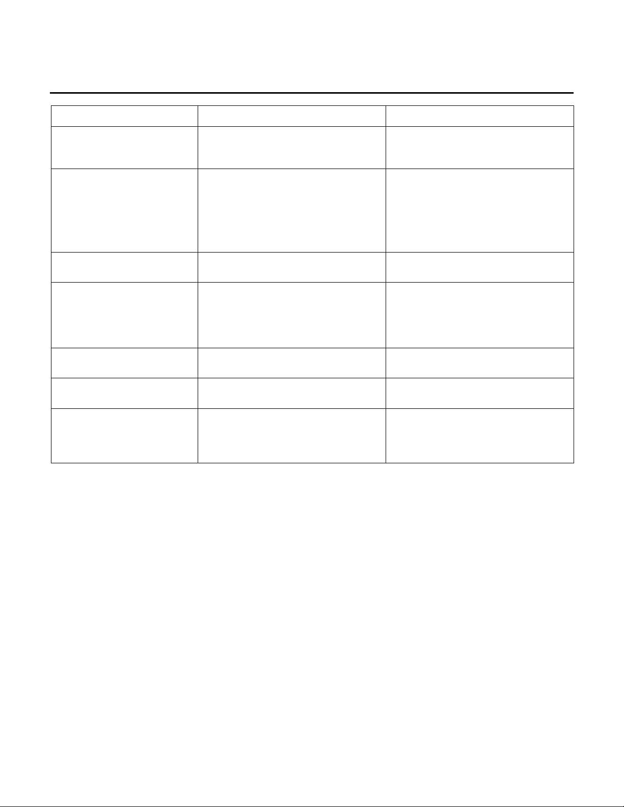
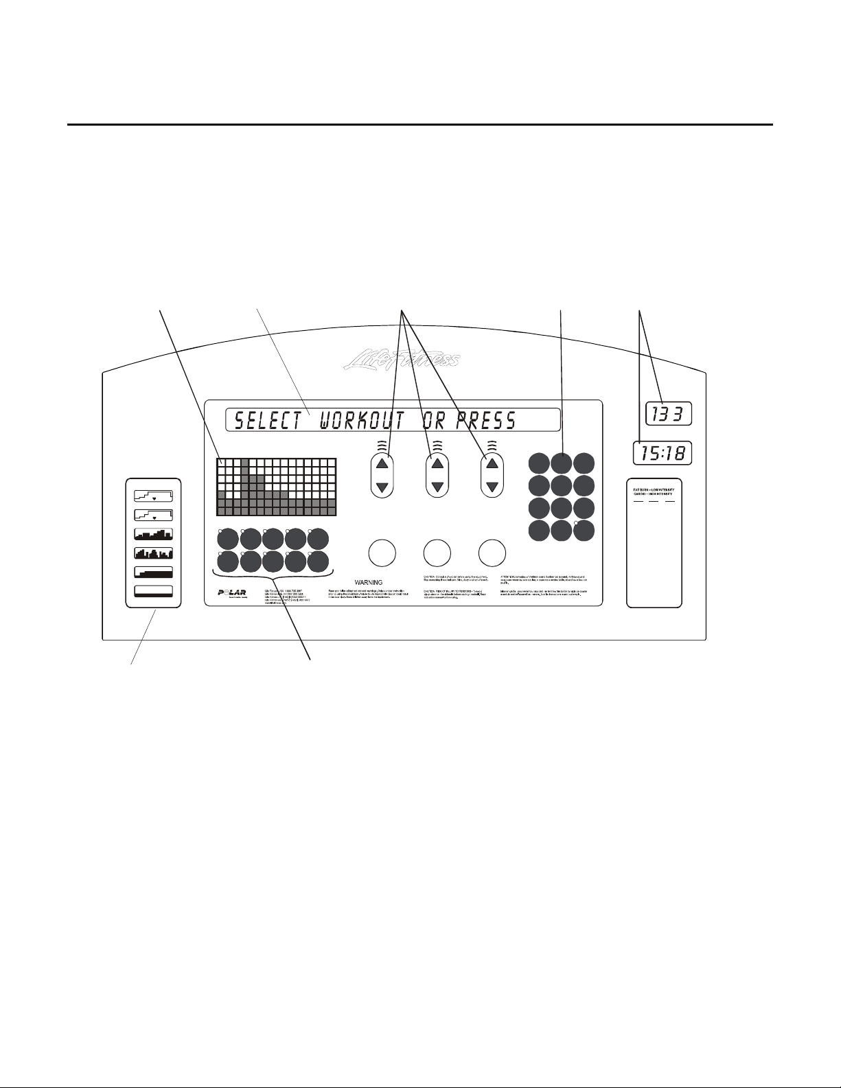
DISPLAY CONSOLES
Use the following to aid you in control and message locations:
Profile
Window
WORKOUT PROFILES
FAT BURN
CARDIO
HILL
RANDOM
FIT TEST
MANUAL
Workout Profile
Information
Message
Center
Fat
Manual
Cardio
Burn
Personal
HillRandom
Trainer
Zone
Enter
Training
Weight
+
Fit
Speed
Test
Interval
Quick
Keys
Up/Down
ArrowsButtons
Quick
Sta rt
Pause
Cool
Down
Numeric
Keypad
Heart RateCalories Distance Time Incline Speed
123
456
809
7
Clear Enter
Display LEDs
Heart Rate
ZONE TRAINING
AGE
65% 80%
136
168
10
Time in Zone
160
130
20
152
123
30
144
117
40
136
110
50
128
104
60
120
97
70
112
91
80
104
90
84
96
78
100
SUGGESTED TARGET
HEART RATE AS % OF MAX
ACSM HEAR T RATE RANGE:
55% - 90%
2A-3
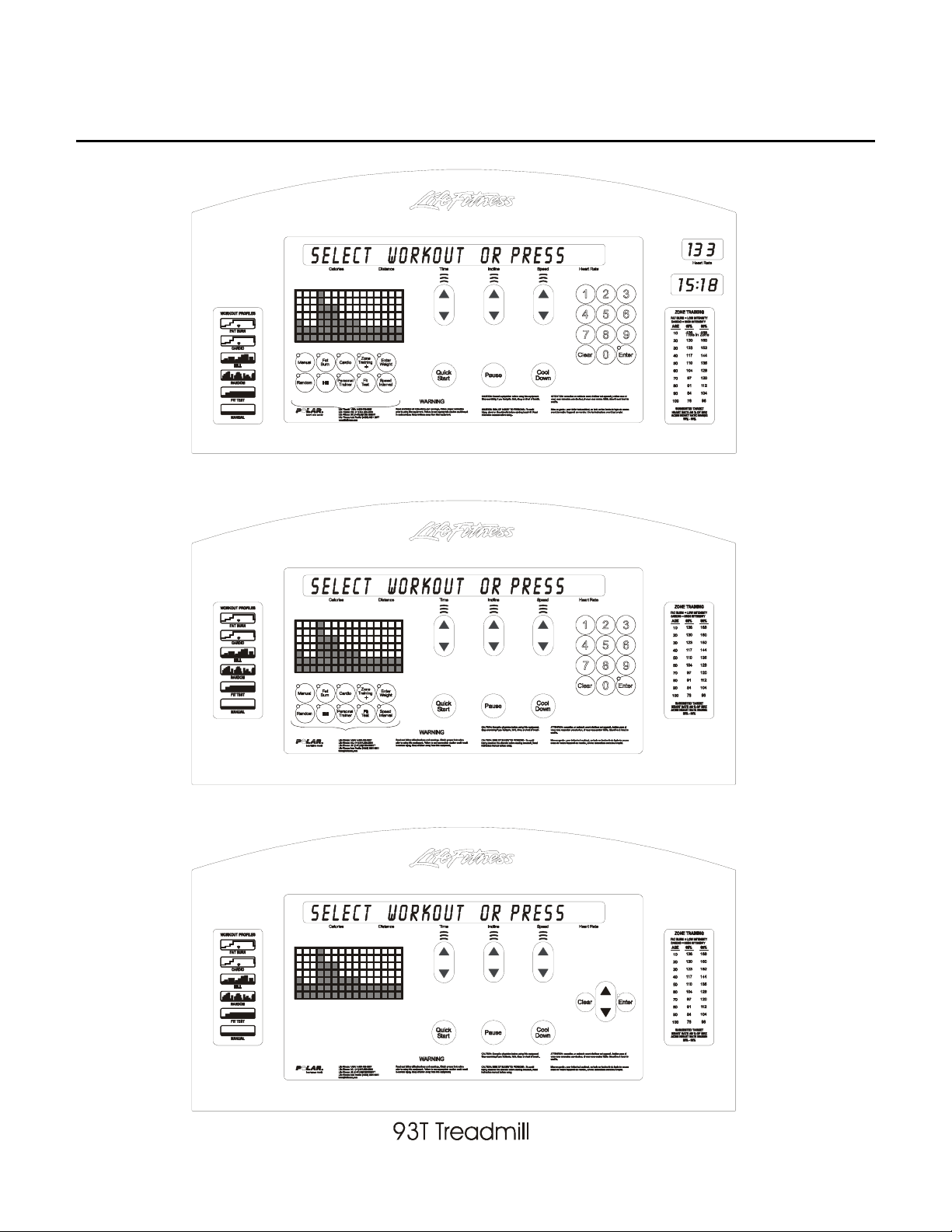
Life Fitness Model 97Te, 95Te, 97Ti, 95Ti and 93T Arctic Silver Treadmills
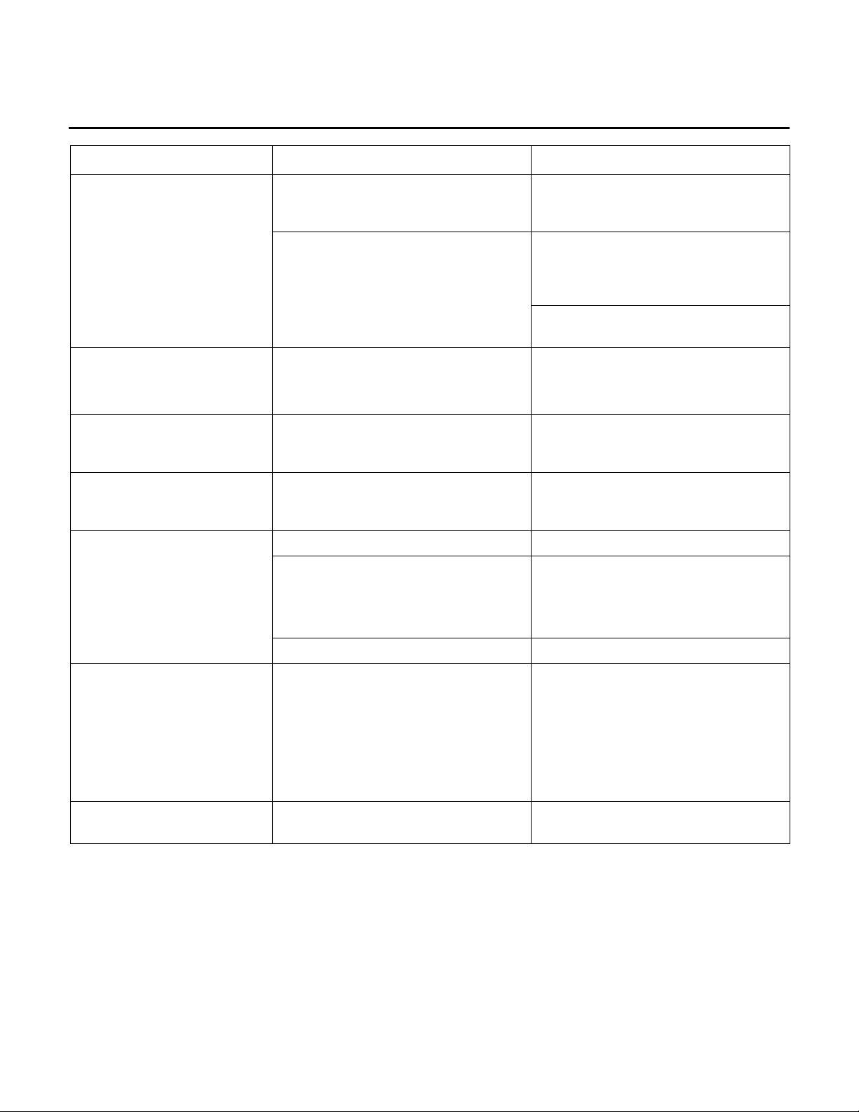
DISPLAY CONSOLES - Continued
97Ti Treadmill
95Ti Treadmill
2A-4
Life Fitness Model 97Te, 95Te, 97Ti, 95Ti and 93T Arctic Silver Treadmills
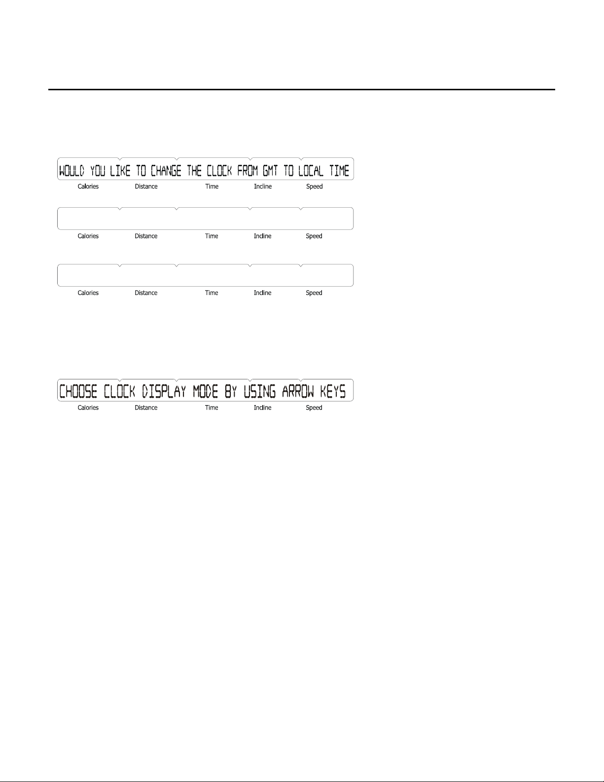
INITIAL SETTING OF THE REAL TIME CLOCK
As part of the initial installation of the treadmill, the real time clock may be configured to the local time. Initially the
real time clock is set to Greenwich meantime (GMT) which is the mean solar time for the meridian at Greenwich,
England, used as a basis for calculating time throughout most of the world. Upon powering up the unit the following
message will be displayed:
IF YES PRESS ENTER
IF NO PRESS CLEAR
If the user wants to set the real time clock to the local time, the user must press the ‘ENTER’ key.
The user will be asked to set the display mode. The two display modes are 12-hour mode with AM/PM or 24 hour
mode with no am/pm. displayed. The message will be:
By pressing any of the arrow keys, the user toggles between the two modes. Once the mode is set, press the
‘ENTER’ key to continue.
After the display mode is set the user will now be asked to set the local time. The following message will appear:
“CLOCK SET TO GMT”,
“USE ARROW KEYS TO ”
“CHANGE SYSTEM CLOCK”,
“TIME KEYS - HOURS”,
“INCLINE KEYS-MINUTES”,
“SPEED KEYS – SECONDS”
By pressing the specific arrow key, the user can set the real time clock to the local time.
After setting the local time, press the ‘CLEAR’ key to exit the real time clock setting mode.
The message “UPDATING CLOCK” will appear in the message center. The unit will then continue with the normal
powering up sequence.
If the user does not want to set up the real time clock at this time, a ‘CLEAR’ key can be pressed to clear the initial
message. The unit will continue with it’s normal powering up sequence. The unit will ask a total of 5 times upon
powering up if the real time clock wants to be set. After the 5th time the message will no longer appear. Refer to
clock configuration to change the clock settings.
2A-5
 Loading...