


Classic Series Recumbent Lifecycle® Exercise Bike
Assembly Instructions

Congratulations...
and welcome to the world of
The following Parts Identification Listing and the step-by-step assembly procedures have been assembled to make the set-up of the Recumbent Exercise Bike as quick and easy as possible.
Please take special note of the following important points prior to choosing a location and beginning assembly of the Recumbent Exercise Bike.

IMPORTANT SAFETY INSTRUCTIONS!
DO NOT locate the Recumbent Exercise Bike outdoors, near swimming pools, or in areas of high humidity.
DO NOT operate your Recumbent Exercise Bike if it has been dropped, damaged, or even partially immersed in water. Contact Life Fitness Customer Support Services at the number in the Operation Manual.
DO NOT locate the Recumbent Exercise Bike any closer than 30 inches (76 cm) to a television set.
DO NOT locate additional Recumbent Exercise Bike any closer than a minimum of 42 inches (107 cm) from center to center to avoid interference (cross talk) between Heart Rate monitors.
DO keep the area around your Recumbent Exercise Bike clear of any obstructions, including walls and furniture.
DO verify the contents of the delivery carton against the accompanying Parts Listing prior to setting the cartons and shipping material aside. If any parts are missing, contact Life Fitness Customer Support Services at the number listed in the Operation Manual. Save the shipping cartons in case of return.
DO read the entire Operation Manual prior to attempting to operate this machine, as this is essential for proper use.
NE PAS placer le vélo d’exercice allongé Lifecycle à l’extérieur, près d’une piscine ou dans un endroit très humide.
NE PAS faire fonctionner le vélo d’exercice allongé Lifecycle s’il est tombé, s’il a été endommagé ou s’il a été partiellement plongé dans l’eau. Téléphoner au service après-vente de Life Fitness dont le numéro figure sur la couverture arrière du guide d’installation.
NE PAS placer le vélo d’exercice allongé Lifecycle à moins de 76 cm (30 po) d’un poste de télévision.
MAINTENIR la zone autour du vélo d’exercice allongé Lifecycle libre de toute obstruction, y compris murs et meubles.
VÉRIFIER si l’emballage contient toutes les pièces de la liste jointe avant de le mettre de côté. Si des pièces manquent, téléphoner au service après-vente de Life Fitness dont le numéro figure sur la couverture arrière du guide d’installation. Conserver l’emballage au cas où l’appareil devrait être renvoyé.
LIRE le manuel de l’utilisateur tout entier avant d’essayer de faire fonctionner cet appareil. Ceci est indispensable à son utilisation correcte.
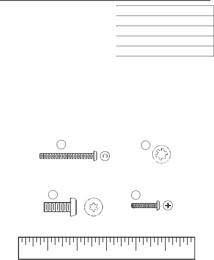
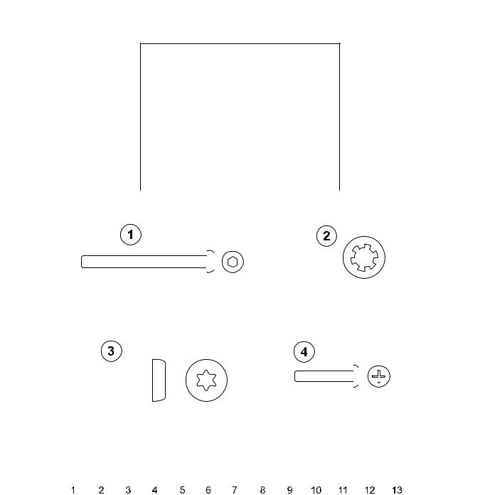
TOOLS REQUIRED FOR ASSEMBLY...Phillips screwdriver, 3/16" hex key wrench, T-40 Torx wrench
PARTS DESCRIPTION
1 |
Seat Back Screw |
Qty: 4 |
|
|
|
3 |
Console Support Assembly Bolt |
Qty: 4 |
|
|
|
5 |
Seat Back |
Qty: 1 |
|
|
|
7 |
Display Console |
Qty: 1 |
|
|
|
9 |
Left Pedal Strap |
Qty: 1 |
|
|
|
2 |
Seat Back Washer |
Qty: 4 |
|
|
|
4 |
Console Screw |
Qty: 4 |
|
|
|
6 |
Console Support Assembly |
Qty: 1 |
|
|
|
8 |
Accessory Tray Assembly |
Qty: 1 |
|
|
|
10 |
Right Pedal Strap |
Qty: 1 |
|
|
|
1 |
2 |
3 |
4 |
1” |
2” |
3” |
4” |
5” |

Please read this prior to assembly.
This product is preconfigured to accept the addition of the Life Fitness Attachable TV System. A POWER CABLE and COAXIAL CABLE have been pre-installed. Please read both the product assembly instructions and Attachable TV System assembly instructions (included with the Life Fitness Attachable TV System) prior to assembly.
Route the POWER CABLE and COAXIAL CABLE alongside the MAIN WIRE HARNESS where applicable.
7
8
4
6 5 


9 |
3 |
|
2
1
10
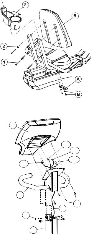
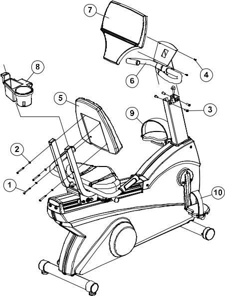
1. Slide the ACCESSORY TRAY (#8) (if so equipped) over the user right seat back post and down to make contact with the SEAT HANDLEBAR.
2.Position the underside clamp bracket (A) around the SEAT HANDLEBAR and tighten the two clamp SCREWS and WASHERS (B).
NOTE: BE CAREFUL NOT TO OVER-TIGHTEN THE SCREWS.
MISE EN GARDE : VEILLER À NE PAS TROP SERRER LA VIS.
3. Align the four holes in the SEAT BACK (#5) with those in the SEAT BACK POSTS. Insert the four SCREWS (#1) and WASHERS (#2) through the backside of the SEAT BACK POSTS and into the SEAT BACK. Tighten the four SCREWS with a hex key wrench.
NOTE: BE CAREFUL NOT TO OVER-TIGHTEN THE SCREWS.
MISE EN GARDE : VEILLER À NE PAS TROP SERRER LA VIS.
4.Unfold the CONSOLE WIRE HARNESSES (C) from the POST extending from the FRAME.
5.Feed the WIRE HARNESSES at the top of the FRAME POST
through the bottom of the CONSOLE SUPPORT ASSEMBLY COLUMN. Continue pushing the WIRE HARNESSES until the CONNECTORS at the end of the WIRE HARNESSES exit
through the opening at the top of the COLUMN. Gently pull the 7 WIRE HARNESSES to remove the slack.
6.Position the CONSOLE SUPPORT ASSEMBLY (#6) so that
the HANDLEBAR is facing the user and slide the CONSOLE SUPPORT ASSEMBLY into the FRAME POST (D), being careful not to pinch the WIRES in the process. Align the holes in the top of the CONSOLE SUPPORT ASSEMBLY with those in the FRAME POST. Install the four CONSOLE SUPPORT ASSEMBLY BOLTS (#3) to secure it into position. Tighten the four CONSOLE SUPPORT ASSEMBLY BOLTS to 15-20 ft. lbs.
NOTE: BE VERY CAREFUL NOT TO DAMAGE THE WIRES WHEN PASSING THE BOLTS THROUGH THE HOLES. TIGHTEN THE BOLTS SECURELY.
MISE EN GARDE :FAITES ATTENTION TRÈS À NE PAS ENDOMMAGER LES FILS EN PASSANT LES BOULONS PAR LES TROUS. SERREZ LES BOULONS SOLIDEMENT.
7.Align the LOCKING TABS of the 10-PIN CONNECTOR and the 4-PIN CONNECTOR and plug them together until they SNAP into place.
8.Carefully feed the wires back into the top of the CONSOLE SUPPORT ASSEMBLY (#6) and attach the DISPLAY CONSOLE (#7) to the CONSOLE SUPPORT ASSEMBLY using the four CONSOLE SCREWS (#4) and a Phillips screwdriver. Tighten the four SCREWS in a criss-cross pattern.
NOTE: BE CAREFUL NOT TO OVER-TIGHTEN THE SCREWS.
MISE EN GARDE : VEILLER À NE PAS TROP SERRER LA VIS.
4P
5P
14P
CX
6

 4 C
4 C
3
D
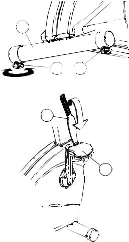
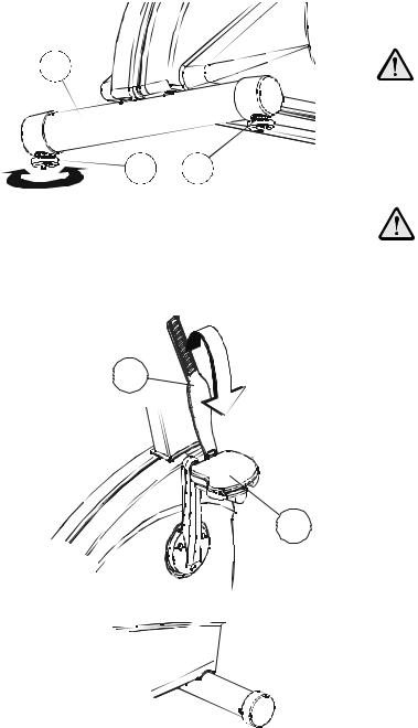
9.After placing the exercise bike in the intended location for use,
check the stability of the bike. If the exercise bike is not level, |
|
turn a LEVELER (G) in the rear STABILIZER BAR (H) in either |
|
direction until the rocking motion is eliminated. Tighten the |
|
JAM NUT (J) when the exercise bike is level. |
H |
NOTE: ONLY ONE LEVELER NEEDS TO BE TURNED. |
|
REMARQUE : NE TOURNER QU’UN SEUL VÉRIN.
10. Locate the RIGHT PEDAL STRAP (#10) marked with an “R”. Attach the RIGHT PEDAL STRAP to the RIGHT PEDAL (K) with the double slot on the inward pedal strap tab looping upward and attaching to the outward pedal strap tab. Repeat for the LEFT PEDAL STRAP (#9) marked with an “L”.
G J
10
K
PHYSICAL DIMENSIONS:
Length: |
54 inches / 137 centimeters |
Width: |
26 inches / 66 centimeters |
Height: |
51 inches / 129 centimeters |
Weight: |
134 pounds / 61 kilograms |
PRE-OPERATION CHECKLIST
Ensure that the console support screws are tight.
Make sure the Recumbent Exercise Bike is properly leveled and stable.
Ensure that the Leveler Jam Nuts are tight.
Read the entire Operation Manual before using the Recumbent Exercise Bike.
LISTE DES VÉRIFICATIONS À EFFECTUER AVANT L’UTILISATION
Vérifiez si les vis de fixation de la console sont serrées.
Vérifiez si le vélo stationnaire allongé est stable et de niveau.
Vérifiez que les contre-écrous des vérins de mise à niveau sont serrés.
Lisez le manuel de l’utilisateur dans son intégralité avant d’utiliser le vélo stationnaire allongé.
Before attempting to operate your Recumbent Exercise Bike, it is imperative that you familiarize yourself with the contents of the Operation Manual. If your Recumbent Exercise Bike does not respond as described in the OPERATION MANUAL, contact the nearest Life Fitness service center as listed in the Operation Manual.
©2008 Life Fitness, a division of Brunswick Corporation. All rights reserved. Life Fitness is trademark of Brunswick Corporation. Polar is a registered trademark of Polar Electro, Inc. MO51-00K39-B168 04/08

Classic Series Lifecycle®Vélos stationnaires allongés
NOTICE DE MONTAGE

Félicitations...
et bienvenue dans le monde de
La liste des pièces et les instructions d’installation détaillées suivantes sont fournies afin de rendre l’installation de ces vélos allongés aussi facile et rapide que possible.
Portez une attention particulière aux points suivants avant de choisir un emplacement pour commencer à monter l’appareil.
2
CONSIGNES DE SECURITE IMPORTANTES !
NE placez PAS le vélo allongé à l’extérieur, près d’une piscine ou dans un endroit très humide.
NE faites PAS fonctionner l’appareil s’il est tombé, s’il a été endommagé ou s’il a été partiellement plongé dans l’eau. Contactez le service après-vente de Life Fitness au numéro fourni dans le manuel d’utilisation.
NE placez PAS le vélo stationnaire allongé à moins de 30 po (76 cm) d’un poste de télévision.
NE placez PAS d’autres vélos stationnaires allongés à proximité. Un espace d’au moins 42 po (107 cm) doit être observé entre les parties centrales de deux appareils afin d’éviter les interférences entre les contrôleurs de fréquence cardiaque.
MAINTENEZ la zone autour de l’appareil exempte de toute obstruction, y compris murs et meubles.
VÉRIFIEZ si l’emballage contient toutes les pièces de la liste jointe avant de le mettre de côté. S’il manque des pièces, contactez le service après-vente de Life Fitness au numéro indiqué dans le manuel d’utilisation. Conserver l’emballage au cas où l’appareil devrait être retourné.
LISEZ le manuel de l’utilisateur en entier avant d’essayer de faire fonctionner cet appareil. Ceci est indispensable à son utilisation correcte.
3
OUTILS NÉCESSAIRES POUR L’INSTALLATION… Tournevis cruciforme, clé hexagonale de 3/16 pouce (47 mm), clé Torx T-40
DESCRIPTION DES PIÈCES
|
|
|
|
|
|
|
|
|
|
|
|
|
|
|
|
|
|
|
1 |
|
|
|
Vis du dossier du siège |
|
|
Qté : 4 |
|
|
|
|
|
|
|
|
|
|
|
|
|
|
|
|
|
|
||||||||||||||||||||||||||||||||||||||||
|
|
|
|
|
|
|
|
|
|
|
|
|
|
|
|
|
|
|
|
|
|
|
|
|
|
|
|
|
|
|
|
|
|
|
|
|
|
|
|
|
|
|
|
|
|
|
|
|
|
|
|
|
|
|
|
|
|
|
|
|
|
|
|
|
|
|
|
|
|
|
|
|
|
|
|
|
|
|
|
|
|
|
|
|
|
|
|
|
|
|
|
|
|
|
|
|
|
|
|
|
|
|
|
2 |
|
|
|
Rondelle du dossier du siège |
|
|
Qté : 4 |
|
|
|
|
|
|
|
|
|
|
|
|
|
|
|
|
|
|||||||||||||||||||||||||||||||||||||||||
|
|
|
|
|
|
|
|
|
|
|
|
|
|
|
|
|
|
|
|
|
|
|
|
|
|
|
|
|
|
|
|
|
|
|
|
|
|
|
|
|
|
|
|
|
|
|
|
|
|
|
|
|
|
|
|
|
|
|
|
|
|
|
|
|
|
|
|
|
|
|
|
|
|
|
|
|
|
|
|
|
|
|
|
|
|
|
|
|
|
|
|
|
|
|
|
|
|
|
|
|
|
|
|
3 |
|
|
|
Boulon de support de console |
|
|
Qté : 4 |
|
|
|
|
|
|
|
|
|
|
|
|
|
|
|
|
|
|||||||||||||||||||||||||||||||||||||||||
|
|
|
|
|
|
|
|
|
|
|
|
|
|
|
|
|
|
|
|
|
|
|
|
|
|
|
|
|
|
|
|
|
|
|
|
|
|
|
|
|
|
|
|
|
|
|
|
|
|
|
|
|
|
|
|
|
|
|
|
|
|
|
|
|
|
|
|
|
|
|
|
|
|
|
|
|
|
|
|
|
|
|
|
|
|
|
|
|
|
|
|
|
|
|
|
|
|
|
|
|
|
|
|
4 |
|
|
|
Vis de la console |
|
|
Qté : 4 |
|
|
|
|
|
|
|
|
|
|
|
|
|
|
|
|
|
|||||||||||||||||||||||||||||||||||||||||
|
|
|
|
|
|
|
|
|
|
|
|
|
|
|
|
|
|
|
|
|
|
|
|
|
|
|
|
|
|
|
|
|
|
|
|
|
|
|
|
|
|
|
|
|
|
|
|
|
|
|
|
|
|
|
|
|
|
|
|
|
|
|
|
|
|
|
|
|
|
|
|
|
|
|
|
|
|
|
|
|
|
|
|
|
|
|
|
|
|
|
|
|
|
|
|
|
|
|
|
|
|
|
|
5 |
|
|
|
Dossier du siège |
|
|
Qté : 1 |
|
|
|
|
|
|
|
|
|
|
|
|
|
|
|
|
|
|||||||||||||||||||||||||||||||||||||||||
|
|
|
|
|
|
|
|
|
|
|
|
|
|
|
|
|
|
|
|
|
|
|
|
|
|
|
|
|
|
|
|
|
|
|
|
|
|
|
|
|
|
|
|
|
|
|
|
|
|
|
|
|
|
|
|
|
|
|
|
|
|
|
|
|
|
|
|
|
|
|
|
|
|
|
|
|
|
|
|
|
|
|
|
|
|
|
|
|
|
|
|
|
|
|
|
|
|
|
|
|
|
|
|
6 |
|
|
|
Support de la console |
|
|
Qté : 1 |
|
|
|
|
|
|
|
|
|
|
|
|
|
|
|
|
|
|||||||||||||||||||||||||||||||||||||||||
|
|
|
|
|
|
|
|
|
|
|
|
|
|
|
|
|
|
|
|
|
|
|
|
|
|
|
|
|
|
|
|
|
|
|
|
|
|
|
|
|
|
|
|
|
|
|
|
|
|
|
|
|
|
|
|
|
|
|
|
|
|
|
|
|
|
|
|
|
|
|
|
|
|
|
|
|
|
|
|
|
|
|
|
|
|
|
|
|
|
|
|
|
|
|
|
|
|
|
|
|
|
|
|
7 |
|
|
|
Console d’affichage |
|
|
Qté : 1 |
|
|
|
|
|
|
|
|
|
|
|
|
|
|
|
|
|
|||||||||||||||||||||||||||||||||||||||||
|
|
|
|
|
|
|
|
|
|
|
|
|
|
|
|
|
|
|
|
|
|
|
|
|
|
|
|
|
|
|
|
|
|
|
|
|
|
|
|
|
|
|
|
|
|
|
|
|
|
|
|
|
|
|
|
|
|
|
|
|
|
|
|
|
|
|
|
|
|
|
|
|
|
|
|
|
|
|
|
|
|
|
|
|
|
|
|
|
|
|
|
|
|
|
|
|
|
|
|
|
|
|
|
8 |
|
|
|
Plateau pour accessoires |
|
|
Qté : 1 |
|
|
|
|
|
|
|
|
|
|
|
|
|
|
|
|
|
|||||||||||||||||||||||||||||||||||||||||
|
|
|
|
|
|
|
|
|
|
|
|
|
|
|
|
|
|
|
|
|
|
|
|
|
|
|
|
|
|
|
|
|
|
|
|
|
|
|
|
|
|
|
|
|
|
|
|
|
|
|
|
|
|
|
|
|
|
|
|
|
|
|
|
|
|
|
|
|
|
|
|
|
|
|
|
|
|
|
|
|
|
|
|
|
|
|
|
|
|
|
|
|
|
|
|
|
|
|
|
|
|
|
|
9 |
|
|
|
Courroie du cale-pied gauche |
|
|
Qté : 1 |
|
|
|
|
|
|
|
|
|
|
|
|
|
|
|
|
|
|||||||||||||||||||||||||||||||||||||||||
|
|
|
|
|
|
|
|
|
|
|
|
|
|
|
|
|
|
|
|
|
|
|
|
|
|
|
|
|
|
|
|
|
|
|
|
|
|
|
|
|
|
|
|
|
|
|
|
|
|
|
|
|
|
|
|
|
|
|
|
|
|
|
|
|
|
|
|
|
|
|
|
|
|
|
|
|
|
|
|
|
|
|
|
|
|
|
|
|
|
|
|
|
|
|
|
|
|
|
|
|
|
|
|
10 |
|
|
Courroie du cale-pied droit |
|
|
Qté : 1 |
|
|
|
|
|
|
|
|
|
|
|
|
|
|
|
|
|
||||||||||||||||||||||||||||||||||||||||||
|
|
|
|
|
|
|
|
|
|
|
|
|
|
|
|
|
|
|
|
|
|
|
|
|
|
|
|
|
|
|
|
|
|
|
|
|
|
|
|
|
|
|
|
|
|
|
|
|
|
|
|
|
|
|
|
|
|
|
|
|
|
|
|
|
|
|
|
|
|
|
|
|
|
|
|
|
|
|
|
|
|
|
|
|
|
|
|
|
|
|
|
|
|
|
|
|
|
|
|
|
|
|
|
|
|
|
|
|
|
|
|
|
|
|
|
|
|
|
|
|
|
|
|
|
|
|
|
|
|
|
|
|
|
|
|
|
|
|
|
|
|
|
|
|
|
|
|
|
|
|
|
|
|
|
|
|
|
|
|
|
|
|
|
|
|
|
|
|
|
|
|
|
|
|
|
|
|
|
|
|
|
|
|
|
|
|
|
|
|
|
|
|
|
|
|
|
|
|
|
|
|
|
|
|
|
|
|
|
|
|
|
|
|
|
|
|
|
|
|
|
|
|
|
|
|
|
|
|
|
|
|
|
|
|
|
|
|
|
|
|
|
|
|
|
|
|
|
|
|
|
|
|
|
|
|
|
|
|
|
|
|
|
|
|
|
|
|
|
|
|
|
|
|
|
|
|
|
|
|
|
|
|
|
|
|
|
|
|
|
|
|
|
|
|
|
|
|
|
|
|
|
|
|
|
|
|
|
|
|
|
|
|
|
|
|
|
|
|
|
|
|
|
|
|
|
|
|
|
|
|
|
|
|
|
|
|
|
|
|
|
|
|
|
|
|
|
|
|
|
|
|
|
|
|
|
|
|
|
|
|
|
|
|
|
|
|
|
|
|
|
|
|
|
|
|
|
|
|
|
|
|
|
|
|
|
|
|
|
|
|
|
|
|
|
|
|
|
|
|
|
|
|
|
|
|
|
|
|
|
|
|
|
|
|
|
|
|
|
|
|
|
|
|
|
|
|
|
|
|
|
|
|
|
|
|
|
|
|
|
|
|
|
|
|
|
|
|
|
|
|
|
|
|
|
|
|
|
|
|
|
|
|
|
|
|
|
|
|
|
|
|
|
|
|
|
|
|
|
|
|
|
|
|
|
|
|
|
|
|
|
|
|
|
|
|
|
|
|
|
|
|
|
|
|
|
|
|
|
|
|
|
|
|
|
|
|
|
|
|
|
|
|
|
|
|
|
|
|
|
|
|
|
|
|
|
|
|
|
|
|
|
|
|
|
|
|
|
|
|
|
|
|
|
|
|
|
|
|
|
|
|
|
|
|
|
|
|
|
|
|
|
|
|
|
|
|
|
|
|
|
|
|
|
|
|
|
|
|
|
|
|
|
|
|
|
|
|
|
|
|
|
|
|
|
|
|
|
|
|
|
|
|
|
|
|
|
|
|
|
|
|
|
|
|
|
|
|
|
|
|
|
|
|
|
|
|
|
|
|
|
|
|
|
|
|
|
|
|
|
|
|
|
|
|
|
|
|
|
|
|
|
|
|
|
|
|
|
|
|
|
|
|
|
|
|
|
|
|
|
|
|
|
|
|
|
|
|
|
|
|
|
|
|
|
|
|
|
|
|
|
|
|
|
|
|
|
|
|
|
|
|
|
|
|
|
|
|
|
|
|
|
|
|
|
|
|
|
|
|
|
|
|
|
|
|
|
|
|
|
|
|
|
|
|
|
|
|
|
|
|
|
|
|
|
|
|
|
|
|
|
|
|
|
|
|
|
|
|
|
|
|
|
|
|
|
|
|
|
|
|
|
|
|
|
|
|
|
|
|
|
|
|
|
|
|
|
|
|
|
|
|
|
|
|
|
|
|
|
|
|
|
|
|
|
|
|
|
|
|
|
|
|
|
|
|
|
|
|
|
|
|
|
|
|
|
|
|
|
|
|
|
|
|
|
|
|
|
|
|
|
|
|
|
|
|
|
|
|
|
|
|
|
|
|
|
|
|
|
|
|
|
|
|
|
|
|
|
|
|
|
|
|
|
|
|
|
|
|
|
|
|
|
|
|
|
|
|
|
|
|
|
|
|
|
|
|
|
|
|
|
|
|
|
|
|
|
|
|
|
|
|
|
|
|
|
|
|
|
|
|
|
|
|
|
|
|
|
|
|
|
|
|
|
|
|
|
|
|
|
|
|
|
|
|
|
|
|
|
|
|
|
|
|
|
|
|
|
|
|
|
|
|
|
|
|
|
|
|
|
|
|
|
|
|
|
|
|
|
|
|
|
|
|
|
|
|
|
|
|
|
|
|
|
|
|
|
|
|
|
|
|
|
|
|
|
|
|
|
|
|
|
|
|
|
|
|
|
|
|
|
|
|
|
|
|
|
|
|
|
|
|
|
|
|
|
|
|
|
|
|
|
|
|
|
|
|
|
|
|
|
|
|
|
|
|
|
|
|
|
|
|
|
|
|
|
|
|
|
|
|
|
|
|
|
|
|
|
|
|
|
|
|
|
|
|
|
|
|
|
|
|
|
|
|
|
|
|
|
|
|
|
|
|
|
|
|
|
|
|
|
|
|
|
|
|
|
|
|
|
|
|
|
|
|
|
|
|
|
|
|
|
|
|
|
|
|
|
|
|
|
|
|
|
|
|
|
|
|
|
|
|
|
|
|
|
|
|
|
|
|
|
|
|
|
|
|
|
|
|
|
|
|
|
|
|
|
|
|
|
4
Veuillez lire attentivement ces instructions avant le montage.
Ce produit est préconfiguré pour le système de téléviseur amovible Life Fitness. Un CÂBLE D’ALIMENTATION et un CÂBLE COAXIAL ont été préinstallés. Veuillez lire les instructions de montage du produit et les instructions d’installation d’téléviseur amovible (livrées avec le système de téléviseur amovible Life Fitness) avant l’installation.
Le cas échéant, acheminez le CÂBLE D’ALIMENTATION et le CÂBLE COAXIAL le long du FAISCEAU ELECTRIQUE PRINCIPAL.
5

7
4P
5P
14P
CX
6
4
C
3
D
1.Faites glisser le PLATEAU D’ACCESSOIRES (nº 8) (si équipé) sur le montant arrière droit du siège et vers le bas jusqu’à ce qu’il touche le GUIDON DU SIÈGE.
2.Placez le dispositif de fixation de la bride de serrage du dessous (A) autour du GUIDON DU SIÈGE, puis serrez les deux VIS et leurs RONDELLES (B).
REMARQUE : VEILLEZ À NE PAS TROP SERRER LES VIS.
3. Alignez les quatre orifices de montage du DOSSIER DU SIÈGE (nº 5) sur ceux des MONTANTS. Insérez les quatre VIS (nº 1) et RONDELLES (nº 2) par l’arrière des MONTANTS DU DOSSIER, dans le DOSSIER DU SIÈGE. Serrez les quatre VIS avec la clé hexagonale.
REMARQUE : VEILLEZ À NE PAS TROP SERRER LES VIS.
4.Dépliez les FAISCEAUX DE CÂBLES DE LA CONSOLE (C) de la TIGE dépassant du CADRE.
5.Passez les FAISCEAUX ÉLECTRIQUES en haut de la TIGE DU CADRE dans le bas de la COLONNE DE SUPPORT DE LA CONSOLE. Continuez de pousser les FAISCEAUX DE CÂBLES jusqu’à ce que les CONNECTEURS situés à leur extrémité sortent par l’ouverture du haut de la COLONNE. Tirez délicatement sur les FAISCEAUX ÉLECTRIQUES pour éliminer le mou.
6.Placez le SUPPORT DE LA CONSOLE (nº 6) de manière à ce que le GUIDON se trouve face à l’utilisateur et faites-le glisser dans la tige du CADRE (D) en veillant à ne pas pincer de FILS. Alignez les trous du haut du SUPPORT DE LA CONSOLE avec ceux de la TIGE DU CADRE. Installez les quatre BOULONS DE SUPPORT DE CONSOLE (nº 3) afin de le fixer en place. Serrez ces quatre BOULONS à un couple de 15-20 ft. lb. (20-27 N.m.).
REMARQUE : VEILLEZ À NE SURTOUT PAS ENDOMMAGER LES FILS LORS DU PASSAGE DES BOULONS DANS LES TROUS. SERREZ FERMEMENT LES BOULONS.
7. Alignez les PATTES DE VERROUILLAGE du CONNECTEUR à 10 BROCHES et du CONNECTEUR à
4 BROCHES et enclenchez-les jusqu’à ce vous entendiez un déclic.
6
H
G J
10
8. Passez avec précautions les fils sur la partie supérieure du SUPPORT DE LA CONSOLE (nº 6) et fixez la CONSOLE D’AFFICHAGE (nº 7) sur son SUPPORT au moyen de quatre VIS DE CONSOLE (nº 4) et du tournevis cruciforme. Serrez les quatre VIS de façon entrecroisée.
REMARQUE : VEILLEZ À NE PAS TROP
SERRER LES VIS.
9. Après avoir placé l’appareil là où vous désirez l’utiliser, vérifiez s’il est stable. S’il est bancal, tournez le DISPOSITIF DE MISE À NIVEAU (G) de la BARRE DE STABILISATION ARRIÈRE (H) dans un sens ou dans l’autre jusqu’à ce qu’il repose à plat. Serrez le CONTREÉCROU (J) une fois que l’appareil est de niveau.
REMARQUE : UN SEUL DISPOSITIF DE MISE
A NIVEAU DOIT ÊTRE TOURNÉ.
10. Repérez la COURROIE CALE-PIED DE DROITE (nº 10) marquée de la lettre « R ». Fixez-la sur la PÉDALE DROITE (K) au moyen de la double fente, en formant une boucle vers le haut entre la languette interne et la languette externe de la pédale. Procédez de même pour la COURROIE CALE-PIED DE GAUCHE (nº 9) marquée de la lettre « L ».
K
7
 Loading...