

Page 1
Machine for
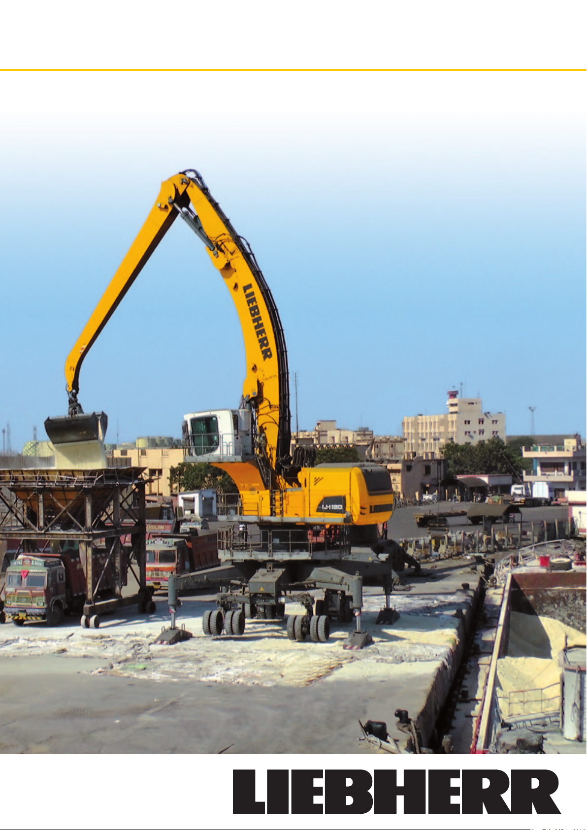
LH 120 M
Industrial Applications
li tr on ic
Operating Weight: 139,900 – 152,500 kg
Engine Output: 400 kW / 543 HP
`
Page 2
Technical Data
Engine
Rating per ISO 9249
�������������������������������
Model
���������������������������������
Type
Bore/Stroke
Displacement
Engine operation
Harmful emissions values
������������������������������
Cooling
Air cleaner
����������������������������
Fuel tank
Engine idling
Electrical system
Voltage
Batteries
Alternator
�������������������������������
Option
����������������
�������������������
�����������������
�������������������
���������������������������
������������������������
������������������������
�����������������������
����������������������
Hydraulic System
Hydraulic pump
for attachment
and travel drive
Max. flow
Max. pressure
Hydraulic pump
regulation and control
Hydraulic pump
for swing drive
Max. flow
Max. pressure
Hydraulic tank
Hydraulic oil filter
Hydraulic oil filter
Hydraulic oil cooler
MODE selection
S (Sensitive)
E (ECO)
P (Power)
P+ (Power-Plus)
����������������
����������������������
�����������������
��������������
����������������
����������������������
�����������������
����������������������
�������������������
�������������������
�����������������
��������������������
�������������������
������������������������
����������������������
���������������
Hydraulic Controls
Power distribution
Servo circuit
Attachment and swing
Driving and steering
Additional functions
������������������
����������������
Swing Drive
���������������������������������
Drive
Transmission
Swing ring
Swing speed
Swing torque
Brake
������������������������
���������������������������
������������������������
������������������������
��������������������������������
400 kW (543 HP) at 1,800 RPM
Liebherr D9508 according to stage IIIA / Tier 3
8 cylinder V-engine
128/157 mm
16.16 l
4-stroke diesel
Common-Rail
turbo-charged and after-cooled
reduced emissions
����������
in accordance with 97/68/EG stagee IIIA
water-cooled with integrated motor oil cooler
dry-type air cleaner with pre-cleaner, primary
and safety elements
3,350 l
sensor controlled
24 V
4 x 170 Ah/12 V
three phase current 28 V/140 A
Liebherr particle filter
four Liebherr variable flow, swashplate pumps
4 x 309 l/min.
350 bar
Positive Control multi-circuit hydraulic system for
independent and demand controlled dosing via the
hydraulic pumps; sensor-controlled
reversible, variable flow, swashplate pump, closed-loop
circuit
483 l/min.
280 bar
1,240 l
1,845 l
3 main return filters with integrated partial micro filtra-
tion (5 μm), 1 high pressure filter for each main pump
cooling system, consisting of a cooling unit for water
and charge air and a 2
with an infinitely variable, thermostatically controlled fan
drive system
adjustment of engine and hydraulic performance via
amode pre-selector to match application, e.g. for
especially economical and environmentally friendly
operation or for maximum material handling and
heavy-duty jobs
for precision work and lifting through very sensitive
movements
for especially economical and environmentally friendly
operation
for maximum digging power and heavy duty jobs
for highest performance and for very heavy duty
applications, suitable for continuous operation
via control valves in single block with integrated safety
valves
��������
with electro-hydraulic pilot control and proportional
operating joysticks
switchable slewing gear (torque or speed control)
����������
with electro-hydraulic pilot control and proportional
operating joystick
proportional control, proportionally acting transmitters
on the joysticks for additional hydraulic functions
Liebherr swashplate motor in a closed system with
integrated brake valve
Liebherr planetary reduction gear
Liebherr, sealed single race ball bearing swing ring,
internal teeth
0 – 5.5 RPM stepless
280 kNm
holding brake (spring applied – pressure released)
nd
cooler for hydraulic oil, each
Uppercarriage
���������������������������������
Type
Operator’s Cab
����������������������������������
Cab
Operator’s seat Standard
�����������
Operator’s seat Comfort (Option)
Operator’s seat Premium (Option)
Control system
Operation and displays
Air-conditioning
Noise emission
ISO 6396
2000/14/EC
���������������������
������������
���������������������
����������������������������
�������������������������
Undercarriage
���������������������������������
Type
���������������������������������
Drive
Travel speed
Axles
Position of wheelsets
Option
Steering programs
Service brake
Holding brake
Stabilization
������������������������
��������������������������������
���������������
�������������������������
������������������
�����������������������
�����������������������
�������������������������
Attachment
���������������������������������
Type
Hydraulic cylinders
Bearings
�����������������
�����������������������������
Complete Machine
Lubrication
Steps system
��������������������������
�����������������������
slewing platform made from high-strength steel plate,
designed for the toughest requirements
spacious operator cabin with profiled design, excellent
view on working area, access from behind, fixed front,
roof and base panel made of bullet proof glass, front
screen with electrical heating, shock-absorbing suspension, sounddamping insulating, sliding window on left
side, sun shadings on all relevant windows, folding seat
forinstructor
air cushioned operator’s seat with headrest, lap belt,
seat heater, manual weight adjustment, adjustable seat
cushion inclination and length and mechanical lumbar
vertebrae support
���
in addition to operator’s seat standard: lockable hori-
zontal suspension, automatic weight adjustment,
adjustable suspension stiffness, pneumatic lumbar
vertebrae support and passive seat climatisation with
active coal
��
in addition to operator’s seat comfort: active elec tronic
weight adjustment (automatic readjustment), pneumatic
low frequency suspension and active seat climatisation
with active coal and ventilator
joysticks with arm consoles and swivel seat
large high-resolution operating unit, selfexplanatory,
colour display with touchscreen, video-compatible,
numerous setting, control and monitoring options,
e.g.air conditioning control, fuel consumption, machine
and tool parameters
standard air conditioning, combined heating-cooling
unit, fast de-icing and demisting at the press of a button,
air vents can be operated via a menu; recirculated air
and fresh air filters can be easily replaced
LpA (inside cab) = 70 dB(A)
LWA (surround noise) = 108 dB(A)
torsion-resistant box design made from high-strength
steel plate, designed for the toughest requirements
per powered wheelset one Liebherr swashplate motor
with integrated brake valves acting on both sides
0 – 7.8 km/h stepless
0 – 4.2 km/h stepless (creeper speed)
wheelsets with suspended 40 t axles, with slewing drive
rotating around the vertical axis, hydraulic cylinder for
leveling
6 steering axles, 2 powered and braked, for leveling
and axle load distribution, interconnected by hydraulic
8 steering axles, 2 powered and braked, for leveling
and axle load distribution, interconnected by hydraulic
front wheel, rear wheel and all-wheel steering,
move to the side in crab steering possible
two circuit travel brake system with accumulator;
maintenance-free, wet and backlash-free disc brake
wet, maintenance-free multi disc brakes
x-shaped 4 point support with 4 folding arms, one
vertically positioned support cylinder per folding arm,
support plates with ball-and-socket joint, removable
high-strength steel plates at highlystressed points
forthe toughest requirements. Complex and stable
mountings of attachment and cylinders
Liebherr cylinders with special seal system.
Shock absorption
sealed, low maintenance
central lubrication system for uppercarriage and
attachment, automatically
central lubrication system for undercarriage,
automatically
undercarriage ascent via ladders (Standard)
undercarriage ascent via ladders and platforms
(HighRise)
uppercarriage with platform left and right and
crossover possibility
parts hot-dip galvanised, nonskid surface
2 LH 120 M Litronic Machine for Industrial Applications
Page 3
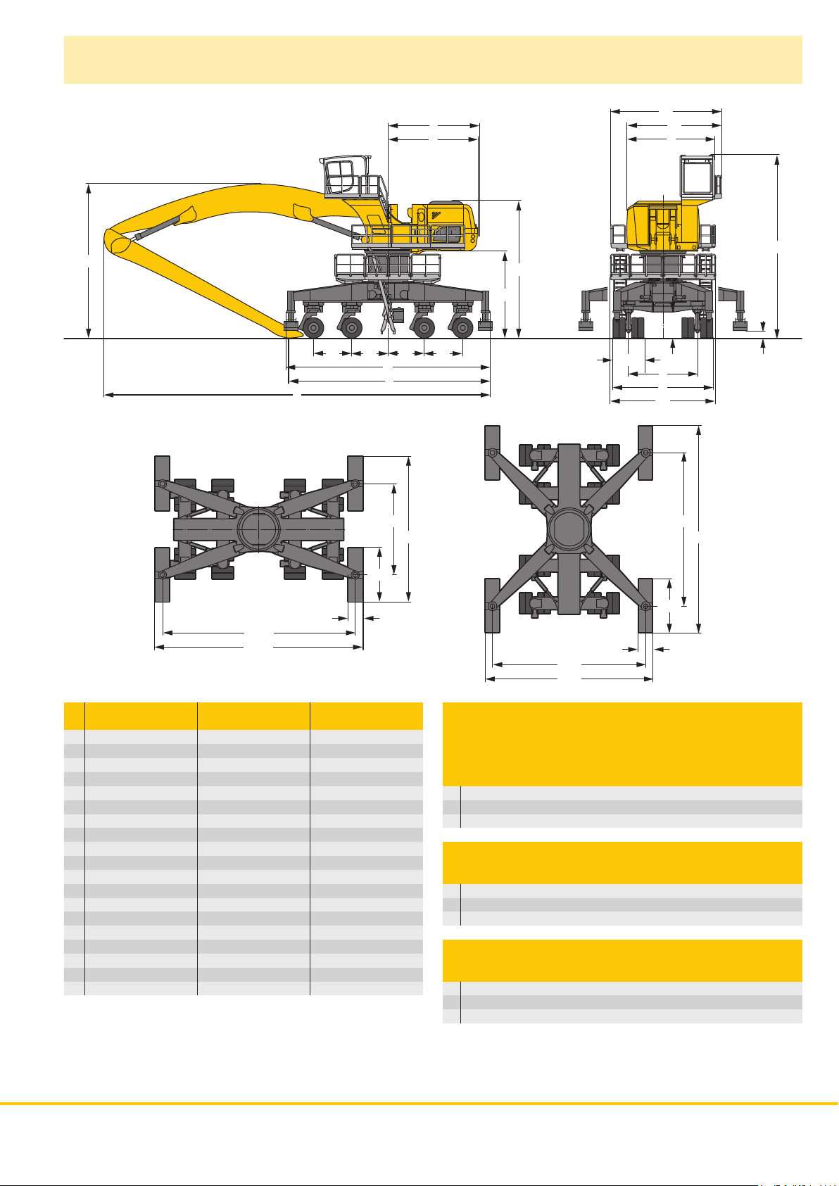
Dimensions
A2
E
D
A1
A
W
L4L3
8050
10686
11486
L1
L2
U
X
V
5050
3000
800
H
K
Q
N
S
B
B1
8500
11500
3000
800
8500
9300
H0290
C
Q1
H0289
without Turret Turret
turret mm 1.20 m mm 2.00 m mm
A 4,814 4,814 4,814
A1 5,220 5,220 5,220
A2 6,115 6,115 6,115
B 5,500 5,500 5,500
B1 – 5,796 5,796
C 8,854 10,054 10,854
D 4,912 4,912 4,912
E 5,020 5,020 5,020
H 6,323 7,523 8,323
K 3,568 4,768 5,568
L1 2,100 2,100 2,100
L2 2,000 2,000 2,000
L3 2,000 2,000 2,000
L4 2,100 2,100 2,100
N 1,700 1,700 1,700
Q 1,431 1,431 1,431
Q1 406 406 406
S 3,800 3,800 3,800
U 11,137 11,137 11,137
E = Tail radius
without Turret Turret
turret 1.20 m 2.00 m
Industrial-Type Angled Mono Boom 15.00 m
and Industrial Stick
m 12.00 13.50 12.00 13.50 12.00 13.50
V mm 11,000 10,350 11,050 10,200 11,150 10,500
W mm 7,950 9,800 8,700 9,950 9,250 10,450
X mm 21,400 21,100 22,100 21,400 21,350 21,450
Industrial-Type Angled Mono Boom 13.50 m
and Industrial Stick
m 10.50 12.00 10.50 12.00 10.50 12.00
V mm 11,050 10,450 11,150 10,600 11,200 10,550
W mm 7,750 9,250 8,600 9,800 9,100 10,100
X mm 19,950 19,800 19,900 20,000 19,850 20,050
Industrial-Type Straight Mono Boom 13.50 m
and Industrial Stick
m 10.50 12.00 10.50 12.00 10.50 12.00
V mm 11,750 11,250 12,200 11,500 12,950 11,350
W mm 7,000 8,750 7,900 9,000 8,700 9,000
X mm 20,000 19,800 20,000 19,950 20,100 20,050
LH 120 M Litronic Machine for Industrial Applications 3
Page 4
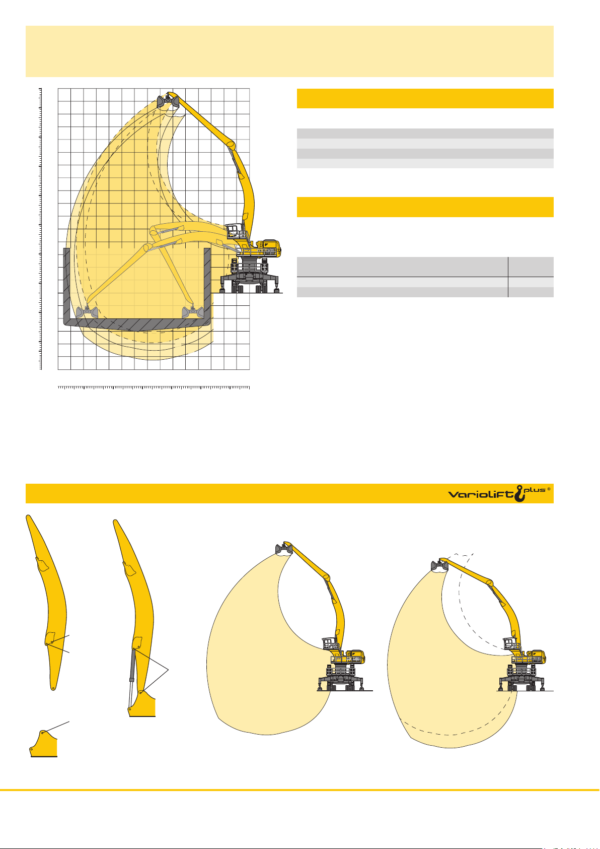
Industrial Attachment
with Industrial-Type Angled Mono Boom 15.00 m
H0292
Attachment Envelope
Kinematic variant 3D
1 with industrial straight stick 12.00 m
2 with industrial straight stick 13.50 m
3 with industrial straight stick 12.00 m and clamshell model GMZ 50
4 with industrial straight stick 13.50 m and clamshell model GMZ 50
Operating Weight
The operating weight includes basic machine with 4 point outriggers,
turret 2.00 m, rigid cab elevation, 32 solid tires and industrial attachment with industrial-type angled mono boom 15.00 m
with clamshell model GMZ 50/6.00 m
shells for loose material Weight
and industrial straight stick 12.00 m 151,900 kg
and industrial straight stick 13.50 m 152,500 kg
100
-10
-20
-30
32
30
28
90
26
80
24
22
70
20
60
18
16
50
14
40
12
10
30
8
10
6
4
10
2
0
0
-2
-4
-6
-8
-10
-12
mft
1
2
3
4
18202224262830
16 14 12 10 8 6 4 2 0
60708090 50 40 30 20 10 0
3
VarioLiftPlus
Hole C
Hole D
Hole 3
H0313
3D
Version 3D
VarioLiftPlus: Variable boom mounting positions for optimized lift capacities
with a different working range
3D
3C
Kinematic Variant 3D:
Increased lift capacities below ground level
and when working at large outreach
Kinematic Variant 3C:
Altered range curve with additional reach
depth, e.g. for unloading from ships
4 LH 120 M Litronic Machine for Industrial Applications
Page 5

Lift Capacities
with Industrial-Type Angled Mono Boom 15.00 m (Kinematic Variant 3D)
Industrial Stick 12.00 m
4.5 m 6.0 m 7.5 m 9.0 m 10.5 m 12.0 m 13.5 m 15.0 m 16.5 m 18.0 m 19.5 m 21.0 m 22.5 m 24.0 m 25.5 m
m Undercarriage m
4 pt. outriggers down
27.0
4 pt. outriggers down
25.5
4 pt. outriggers down
24.0
4 pt. outriggers down
22.5
4 pt. outriggers down
21.0
4 pt. outriggers down
19.5
4 pt. outriggers down
18.0
4 pt. outriggers down
16.5
4 pt. outriggers down
15.0
4 pt. outriggers down
13.5
4 pt. outriggers down
12.0
4 pt. outriggers down
10.5
4 pt. outriggers down
9.0
4 pt. outriggers down
7.5
4 pt. outriggers down
6.0
4 pt. outriggers down
4.5
4 pt. outriggers down
3.0
4 pt. outriggers down
1.5
4 pt. outriggers down
0
4 pt. outriggers down
– 1.5
4 pt. outriggers down
– 3.0
4 pt. outriggers down
– 4.5
4 pt. outriggers down
– 6.0
4 pt. outriggers down
– 7.5
4 pt. outriggers down
– 9.0
4 pt. outriggers down
– 10.5
10.6* 10.6* 10.0* 10.0* 13.8
10.9* 10.9* 9.3* 9.3* 16.0
10.8* 10.8* 10.1* 10.1* 8.8* 8.8* 17.7
10.7* 10.7* 9.9* 9.9* 9.4* 9.4* 8.5* 8.5* 19.1
10.6* 10.6* 9.9* 9.9* 9.3* 9.3* 8.7* 8.7* 8.2* 8.2* 20.4
10.6* 10.6* 9.8* 9.8* 9.2* 9.2* 8.7* 8.7* 8.2* 8.2* 8.1* 8.1* 21.4
10.6* 10.6* 9.9* 9.9* 9.2* 9.2* 8.7* 8.7* 8.2* 8.2* 7.9* 7.9* 22.3
10.7* 10.7* 9.9* 9.9* 9.3* 9.3* 8.7* 8.7* 8.2* 8.2* 7.8* 7.8* 7.6* 7.6* 23.1
11.8* 11.8* 10.9* 10.9* 10.1* 10.1* 9.4* 9.4* 8.8* 8.8* 8.2* 8.2* 7.8* 7.8* 7.5* 7.5* 23.8
12.1* 12.1* 11.1* 11.1* 10.2* 10.2* 9.5* 9.5* 8.8* 8.8* 8.3* 8.3* 7.8* 7.8* 7.4* 7.4* 7.3* 7.3* 24.3
13.8* 13.8* 12.4* 12.4* 11.3* 11.3* 10.4* 10.4* 9.6* 9.6* 9.0* 9.0* 8.4* 8.4* 7.9* 7.9* 7.4* 7.4* 7.2* 7.2* 24.7
16.2* 16.2* 14.3* 14.3* 12.8* 12.8* 11.6* 11.6* 10.6* 10.6* 9.8* 9.8* 9.1* 9.1* 8.5* 8.5* 7.9* 7.9* 7.5* 7.5* 7.2* 7.2* 25.1
29.9* 29.9* 23.8* 23.8* 19.8* 19.8* 17.0* 17.0* 14.9* 14.9* 13.2* 13.2* 11.9* 11.9* 10.8* 10.8* 10.0* 10.0* 9.2* 9.2* 8.6* 8.6* 8.0* 8.0* 7.5* 7.5* 7.1* 7.1* 25.3
22.7* 22.7* 32.8* 32.8* 25.5* 25.5* 20.9* 20.9* 17.8* 17.8* 15.4* 15.4* 13.6* 13.6* 12.2* 12.2* 11.1* 11.1* 10.1* 10.1* 9.3* 9.3* 8.7* 8.7* 8.1* 8.1* 7.6* 7.6* 7.1* 7.1* 25.5
5.8* 5.8* 17.3* 17.3* 27.1* 27.1* 22.0* 22.0* 18.5* 18.5* 16.0* 16.0* 14.0* 14.0* 12.5* 12.5* 11.3* 11.3* 10.3* 10.3* 9.5* 9.5* 8.8* 8.8* 8.2* 8.2* 7.6* 7.6* 7.1* 7.1* 7.1* 7.1* 25.5
4.0* 4.0* 9.9* 9.9* 20.8* 20.8* 22.9* 22.9* 19.2* 19.2* 16.5* 16.5* 14.4* 14.4* 12.8* 12.8* 11.5* 11.5* 10.5* 10.5* 9.6* 9.6* 8.9* 8.9* 8.2* 8.2* 7.6* 7.6* 7.1* 7.1* 25.5
4.3* 4.3* 8.2* 8.2* 14.7* 14.7* 23.6* 23.6* 19.7* 19.7* 16.9* 16.9* 14.7* 14.7* 13.1* 13.1* 11.7* 11.7* 10.6* 10.6* 9.7* 9.7* 8.9* 8.9* 8.3* 8.3* 7.6* 7.6* 7.1* 7.1* 25.4
5.2* 5.2* 8.1* 8.1* 12.8* 12.8* 20.8* 20.8* 20.1* 20.1* 17.2* 17.2* 15.0* 15.0* 13.3* 13.3* 11.9* 11.9* 10.8* 10.8* 9.8* 9.8* 9.0* 9.0* 8.3* 8.3* 7.6* 7.6* 7.1* 7.1* 25.2
6.3* 6.3* 8.6* 8.6* 12.3* 12.3* 18.3* 18.3* 20.3* 20.3* 17.4* 17.4* 15.2* 15.2* 13.4* 13.4* 12.0* 12.0* 10.8* 10.8* 9.8* 9.8* 9.0* 9.0* 8.3* 8.3* 7.5* 7.5* 7.1* 7.1* 24.8
7.3* 7.3* 9.3* 9.3* 12.4* 12.4* 17.3* 17.3* 20.3* 20.3* 17.4* 17.4* 15.2* 15.2* 13.5* 13.5* 12.0* 12.0* 10.8* 10.8* 9.8* 9.8* 9.0* 9.0* 8.2* 8.2* 7.4* 7.4* 7.2* 7.2* 24.4
10.1* 10.1* 12.8* 12.8* 17.0* 17.0* 20.1* 20.1* 17.3* 17.3* 15.1* 15.1* 13.4* 13.4* 12.0* 12.0* 10.8* 10.8* 9.7* 9.7* 8.8* 8.8* 8.0* 8.0* 7.2* 7.2* 23.9
13.4* 13.4* 17.2* 17.2* 19.6* 19.6* 17.0* 17.0* 14.9* 14.9* 13.2* 13.2* 11.8* 11.8* 10.6* 10.6* 9.5* 9.5* 8.6* 8.6* 7.7* 7.7* 7.2* 7.2* 23.3
17.7* 17.7* 18.9* 18.9* 16.5* 16.5* 14.5* 14.5* 12.9* 12.9* 11.5* 11.5* 10.3* 10.3* 9.2* 9.2* 8.2* 8.2* 7.4* 7.4* 22.1
15.7* 15.7* 13.9* 13.9* 12.3* 12.3* 11.0* 11.0* 9.8* 9.8* 8.9* 8.9* 19.2
Industrial Stick 13.50 m
4.5 m 6.0 m 7.5 m 9.0 m 10.5 m 12.0 m 13.5 m 15.0 m 16.5 m 18.0 m 19.5 m 21.0 m 22.5 m 24.0 m 25.5 m
m Undercarriage m
4 pt. outriggers down
27.0
4 pt. outriggers down
25.5
4 pt. outriggers down
24.0
4 pt. outriggers down
22.5
4 pt. outriggers down
21.0
4 pt. outriggers down
19.5
4 pt. outriggers down
18.0
4 pt. outriggers down
16.5
4 pt. outriggers down
15.0
4 pt. outriggers down
13.5
4 pt. outriggers down
12.0
4 pt. outriggers down
10.5
4 pt. outriggers down
9.0
4 pt. outriggers down
7.5
4 pt. outriggers down
6.0
4 pt. outriggers down
4.5
4 pt. outriggers down
3.0
4 pt. outriggers down
1.5
4 pt. outriggers down
0
4 pt. outriggers down
– 1.5
4 pt. outriggers down
– 3.0
4 pt. outriggers down
– 4.5
4 pt. outriggers down
– 6.0
4 pt. outriggers down
– 7.5
4 pt. outriggers down
– 9.0
4 pt. outriggers down
– 10.5
Height Can be slewed through 360° In longitudinal position of undercarriage Max. reach * Limited by hydr. capacity
The lift capacities on the stick end without attachment are stated in metric tons (t) and are valid on a firm, level supporting surface. These capacities
can be slewed through 360° with the undercarriage in the transverse position. Indicated loads comply with the ISO 10567 standard and do not
exceed 75 % of tipping or 87 % of hydraulic capacity. The lift capacity of the unit is limited by its stability, the lifting capability of the hydraulic
elements, or the maximum permissible lifting capacity of the load hook.
In accordance with the harmonised European Standard EN 474-5, hydraulic excavators used for lifting operations must be equipped with pipe
fracturesafety valves, an overload warning device, a load hook and a lift capacity chart.
8.9* 8.9* 14.1
9.9* 9.9* 8.2* 8.2* 16.3
9.5* 9.5* 7.9* 7.9* 7.7* 7.7* 18.1
9.3* 9.3* 8.8* 8.8* 7.6* 7.6* 7.3* 7.3* 19.6
9.2* 9.2* 8.7* 8.7* 8.2* 8.2* 7.1* 7.1* 21.0
9.2* 9.2* 8.6* 8.6* 8.1* 8.1* 7.7* 7.7* 6.9* 6.9* 22.1
9.2* 9.2* 8.6* 8.6* 8.1* 8.1* 7.6* 7.6* 7.2* 7.2* 6.8* 6.8* 23.1
9.2* 9.2* 8.6* 8.6* 8.1* 8.1* 7.6* 7.6* 7.2* 7.2* 6.7* 6.7* 23.9
9.3* 9.3* 8.6* 8.6* 8.1* 8.1* 7.6* 7.6* 7.2* 7.2* 6.8* 6.8* 6.6* 6.6* 24.6
10.1* 10.1* 9.4* 9.4* 8.7* 8.7* 8.2* 8.2* 7.7* 7.7* 7.2* 7.2* 6.8* 6.8* 6.6* 6.6* 25.2
10.3* 10.3* 9.5* 9.5* 8.8* 8.8* 8.2* 8.2* 7.7* 7.7* 7.3* 7.3* 6.9* 6.9* 6.5* 6.5* 6.4* 6.4* 25.8
11.6* 11.6* 10.6* 10.6* 9.7* 9.7* 9.0* 9.0* 8.3* 8.3* 7.8* 7.8* 7.3* 7.3* 6.9* 6.9* 6.5* 6.5* 6.4* 6.4* 26.2
13.3* 13.3* 12.0* 12.0* 10.9* 10.9* 9.9* 9.9* 9.1* 9.1* 8.5* 8.5* 7.9* 7.9* 7.4* 7.4* 6.9* 6.9* 6.5* 6.5* 6.3* 6.3* 26.5
15.7* 15.7* 13.8* 13.8* 12.4* 12.4* 11.1* 11.1* 10.2* 10.2* 9.3* 9.3* 8.6* 8.6* 8.0* 8.0* 7.5* 7.5* 7.0* 7.0* 6.6* 6.6* 6.3* 6.3* 26.7
29.4* 29.4* 23.3* 23.3* 19.3* 19.3* 16.5* 16.5* 14.4* 14.4* 12.8* 12.8* 11.5* 11.5* 10.4* 10.4* 9.5* 9.5* 8.7* 8.7* 8.1* 8.1* 7.5* 7.5* 7.1* 7.1* 6.6* 6.6* 6.2* 6.2* 26.8
24.9* 24.9* 32.2* 32.2* 25.0* 25.0* 20.4* 20.4* 17.3* 17.3* 14.9* 14.9* 13.2* 13.2* 11.8* 11.8* 10.6* 10.6* 9.7* 9.7* 8.9* 8.9* 8.2* 8.2* 7.6* 7.6* 7.1* 7.1* 6.6* 6.6* 6.2* 6.2* 26.9
7.9* 7.9* 19.1* 19.1* 26.4* 26.4* 21.4* 21.4* 18.0* 18.0* 15.5* 15.5* 13.6* 13.6* 12.1* 12.1* 10.9* 10.9* 9.9* 9.9* 9.0* 9.0* 8.3* 8.3* 7.7* 7.7* 7.2* 7.2* 6.7* 6.7* 6.2* 6.2* 26.9
5.9* 5.9* 11.4* 11.4* 22.1* 22.1* 22.2* 22.2* 18.6* 18.6* 15.9* 15.9* 13.9* 13.9* 12.3* 12.3* 11.1* 11.1* 10.0* 10.0* 9.2* 9.2* 8.4* 8.4* 7.8* 7.8* 7.2* 7.2* 6.7* 6.7* 6.3* 6.3* 26.8
5.9* 5.9* 9.5* 9.5* 15.9* 15.9* 22.8* 22.8* 19.0* 19.0* 16.3* 16.3* 14.2* 14.2* 12.6* 12.6* 11.3* 11.3* 10.2* 10.2* 9.3* 9.3* 8.5* 8.5* 7.8* 7.8* 7.2* 7.2* 6.7* 6.7* 6.3* 6.3* 26.6
6.3* 6.3* 9.2* 9.2* 13.7* 13.7* 21.6* 21.6* 19.4* 19.4* 16.6* 16.6* 14.4* 14.4* 12.7* 12.7* 11.4* 11.4* 10.3* 10.3* 9.3* 9.3* 8.5* 8.5* 7.8* 7.8* 7.2* 7.2* 6.6* 6.6* 6.3* 6.3* 26.3
7.0* 7.0* 9.3* 9.3* 12.9* 12.9* 18.8* 18.8* 19.6* 19.6* 16.7* 16.7* 14.6* 14.6* 12.9* 12.9* 11.5* 11.5* 10.3* 10.3* 9.4* 9.4* 8.6* 8.6* 7.8* 7.8* 7.2* 7.2* 6.5* 6.5* 6.3* 6.3* 25.9
7.7* 7.7* 9.8* 9.8* 12.8* 12.8* 17.6* 17.6* 19.5* 19.5* 16.8* 16.8* 14.6* 14.6* 12.9* 12.9* 11.5* 11.5* 10.3* 10.3* 9.4* 9.4* 8.5* 8.5* 7.7* 7.7* 7.0* 7.0* 6.3* 6.3* 25.4
10.3* 10.3* 13.0* 13.0* 17.2* 17.2* 19.3* 19.3* 16.6* 16.6* 14.5* 14.5* 12.8* 12.8* 11.4* 11.4* 10.3* 10.3* 9.3* 9.3* 8.4* 8.4* 7.6* 7.6* 6.8* 6.8* 6.4* 6.4* 24.8
10.9* 10.9* 13.4* 13.4* 17.2* 17.2* 18.9* 18.9* 16.3* 16.3* 14.3* 14.3* 12.6* 12.6* 11.3* 11.3* 10.1* 10.1* 9.1* 9.1* 8.2* 8.2* 7.3* 7.3* 6.4* 6.4* 6.3* 6.3* 24.2
17.5* 17.5* 18.2* 18.2* 15.8* 15.8* 13.9* 13.9* 12.3* 12.3* 10.9* 10.9* 9.8* 9.8* 8.7* 8.7* 7.8* 7.8* 6.9* 6.9* 6.8* 6.8* 22.6
15.1* 15.1* 13.2* 13.2* 11.7* 11.7* 10.4* 10.4* 9.3* 9.3* 8.2* 8.2* 19.5
LH 120 M Litronic Machine for Industrial Applications 5
Page 6

Industrial Attachment
with Industrial-Type Angled Mono Boom 13.50 m
90
80
70
60
50
40
30
20
10
-10
-20
-30
28
26
24
22
20
18
16
14
12
10
8
6
4
2
0
0
-2
-4
-10
-12
-6
-8
mft
1820222426
607080 50 40 30 20 10 0
1
2
3
4
16 14 12 10 8 6 4 2 0
H0312
Attachment Envelope
Kinematic variant 3D
1 with industrial stick 10.50 m
2 with industrial stick 12.00 m
3 with industrial stick 10.50 m and grapple model GMM 120
4 with industrial stick 12.00 m and grapple model GMM 120
Operating Weight
The operating weight includes basic machine with 4 point outriggers,
rigid cab elevation, 32 solid tires and industrial attachment with
industrial-type angled mono boom 13.50 m
with grapple model GMM 120-5/3.00 m
semi-closed tines Weight
and industrial stick 10.50 m 140,950 kg
and industrial stick 12.00 m 141,500 kg
3
VarioLiftPlus
Hole C
Hole D
Hole 3
H0313
3D
Version 3D
VarioLiftPlus: Variable boom mounting positions for optimized lift capacities
with a different working range
3D
3C
Kinematic Variant 3D:
Increased lift capacities below ground level
and when working at large outreach
Kinematic Variant 3C:
Altered range curve with additional reach
depth, e.g. for unloading from ships
6 LH 120 M Litronic Machine for Industrial Applications
Page 7

Lift Capacities
with Industrial-Type Angled Mono Boom 13.50 m (Kinematic Variant 3D)
Industrial Stick 10.50 m
4.5 m 6.0 m 7.5 m 9.0 m 10.5 m 12.0 m 13.5 m 15.0 m 16.5 m 18.0 m 19.5 m 21.0 m 22.5 m 24.0 m 25.5 m
m Undercarriage m
4 pt. outriggers down
27.0
4 pt. outriggers down
25.5
4 pt. outriggers down
24.0
4 pt. outriggers down
22.5
4 pt. outriggers down
21.0
4 pt. outriggers down
19.5
4 pt. outriggers down
18.0
4 pt. outriggers down
16.5
4 pt. outriggers down
15.0
4 pt. outriggers down
13.5
4 pt. outriggers down
12.0
4 pt. outriggers down
10.5
4 pt. outriggers down
9.0
4 pt. outriggers down
7.5
4 pt. outriggers down
6.0
4 pt. outriggers down
4.5
4 pt. outriggers down
3.0
4 pt. outriggers down
1.5
4 pt. outriggers down
0
4 pt. outriggers down
– 1.5
4 pt. outriggers down
– 3.0
4 pt. outriggers down
– 4.5
4 pt. outriggers down
– 6.0
4 pt. outriggers down
– 7.5
4 pt. outriggers down
– 9.0
4 pt. outriggers down
– 10.5
12.8* 12.8* 11.7* 11.7* 12.5
13.1* 13.1* 10.9* 10.9* 14.6
12.8* 12.8* 12.1* 12.1* 10.3* 10.3* 16.2
12.6* 12.6* 11.9* 11.9* 11.4* 11.4* 9.9* 9.9* 17.6
12.6* 12.6* 11.9* 11.9* 11.3* 11.3* 10.8* 10.8* 9.7* 9.7* 18.7
12.7* 12.7* 11.9* 11.9* 11.3* 11.3* 10.7* 10.7* 10.1* 10.1* 9.6* 9.6* 19.7
12.9* 12.9* 12.0* 12.0* 11.3* 11.3* 10.8* 10.8* 10.3* 10.3* 9.5* 9.5* 20.5
14.2* 14.2* 13.1* 13.1* 12.3* 12.3* 11.5* 11.5* 10.9* 10.9* 10.3* 10.3* 9.9* 9.9* 9.5* 9.5* 21.1
16.2* 16.2* 14.7* 14.7* 13.5* 13.5* 12.5* 12.5* 11.7* 11.7* 11.0* 11.0* 10.4* 10.4* 9.9* 9.9* 9.5* 9.5* 21.7
19.3* 19.3* 17.1* 17.1* 15.4* 15.4* 14.0* 14.0* 12.9* 12.9* 12.0* 12.0* 11.2* 11.2* 10.5* 10.5* 10.0* 10.0* 9.6* 9.6* 22.1
24.4* 24.4* 20.7* 20.7* 18.1* 18.1* 16.1* 16.1* 14.5* 14.5* 13.3* 13.3* 12.3* 12.3* 11.4* 11.4* 10.7* 10.7* 10.1* 10.1* 9.6* 9.6* 22.4
46.6* 46.6* 33.8* 33.8* 26.8* 26.8* 22.3* 22.3* 19.1* 19.1* 16.8* 16.8* 15.1* 15.1* 13.7* 13.7* 12.6* 12.6* 11.6* 11.6* 10.9* 10.9* 10.2* 10.2* 9.6* 9.6* 9.6* 9.6* 22.6
10.5* 10.5* 35.3* 35.3* 29.1* 29.1* 23.8* 23.8* 20.2* 20.2* 17.6* 17.6* 15.7* 15.7* 14.1* 14.1* 12.9* 12.9* 11.9* 11.9* 11.0* 11.0* 10.3* 10.3* 9.7* 9.7* 9.6* 9.6* 22.7
5.9* 5.9* 15.2* 15.2* 31.1* 31.1* 25.2* 25.2* 21.2* 21.2* 18.3* 18.3* 16.2* 16.2* 14.5* 14.5* 13.2* 13.2* 12.1* 12.1* 11.2* 11.2* 10.4* 10.4* 9.7* 9.7* 9.6* 9.6* 22.7
5.8* 5.8* 11.5* 11.5* 22.0* 22.0* 26.3* 26.3* 22.0* 22.0* 19.0* 19.0* 16.7* 16.7* 14.9* 14.9* 13.5* 13.5* 12.3* 12.3* 11.3* 11.3* 10.5* 10.5* 9.7* 9.7* 9.6* 9.6* 22.6
6.8* 6.8* 10.9* 10.9* 17.9* 17.9* 27.0* 27.0* 22.7* 22.7* 19.5* 19.5* 17.1* 17.1* 15.2* 15.2* 13.7* 13.7* 12.5* 12.5* 11.4* 11.4* 10.5* 10.5* 9.7* 9.7* 22.4
8.0* 8.0* 11.3* 11.3* 16.7* 16.7* 26.3* 26.3* 23.0* 23.0* 19.8* 19.8* 17.3* 17.3* 15.4* 15.4* 13.8* 13.8* 12.6* 12.6* 11.5* 11.5* 10.5* 10.5* 9.8* 9.8* 22.1
12.1* 12.1* 16.5* 16.5* 24.2* 24.2* 23.1* 23.1* 19.9* 19.9* 17.4* 17.4* 15.5* 15.5* 13.9* 13.9* 12.5* 12.5* 11.4* 11.4* 10.3* 10.3* 9.8* 9.8* 21.7
13.0* 13.0* 16.9* 16.9* 23.5* 23.5* 22.9* 22.9* 19.8* 19.8* 17.4* 17.4* 15.4* 15.4* 13.8* 13.8* 12.4* 12.4* 11.2* 11.2* 9.9* 9.9* 9.8* 9.8* 21.1
17.6* 17.6* 23.6* 23.6* 22.4* 22.4* 19.4* 19.4* 17.1* 17.1* 15.1* 15.1* 13.5* 13.5* 12.1* 12.1* 10.7* 10.7* 9.8* 9.8* 20.5
21.5* 21.5* 18.7* 18.7* 16.5* 16.5* 14.6* 14.6* 12.9* 12.9* 11.5* 11.5* 11.3* 11.3* 18.2
Industrial Stick 12.00 m
4.5 m 6.0 m 7.5 m 9.0 m 10.5 m 12.0 m 13.5 m 15.0 m 16.5 m 18.0 m 19.5 m 21.0 m 22.5 m 24.0 m 25.5 m
m Undercarriage m
4 pt. outriggers down
27.0
4 pt. outriggers down
25.5
4 pt. outriggers down
24.0
4 pt. outriggers down
22.5
4 pt. outriggers down
21.0
4 pt. outriggers down
19.5
4 pt. outriggers down
18.0
4 pt. outriggers down
16.5
4 pt. outriggers down
15.0
4 pt. outriggers down
13.5
4 pt. outriggers down
12.0
4 pt. outriggers down
10.5
4 pt. outriggers down
9.0
4 pt. outriggers down
7.5
4 pt. outriggers down
6.0
4 pt. outriggers down
4.5
4 pt. outriggers down
3.0
4 pt. outriggers down
1.5
4 pt. outriggers down
0
4 pt. outriggers down
– 1.5
4 pt. outriggers down
– 3.0
4 pt. outriggers down
– 4.5
4 pt. outriggers down
– 6.0
4 pt. outriggers down
– 7.5
4 pt. outriggers down
– 9.0
4 pt. outriggers down
– 10.5
Height Can be slewed through 360° In longitudinal position of undercarriage Max. reach * Limited by hydr. capacity
The lift capacities on the stick end without attachment are stated in metric tons (t) and are valid on a firm, level supporting surface. These capacities
can be slewed through 360° with the undercarriage in the transverse position. Indicated loads comply with the ISO 10567 standard and do not
exceed 75 % of tipping or 87 % of hydraulic capacity. The lift capacity of the unit is limited by its stability, the lifting capability of the hydraulic
elements, or the maximum permissible lifting capacity of the load hook.
In accordance with the harmonised European Standard EN 474-5, hydraulic excavators used for lifting operations must be equipped with pipe
fracturesafety valves, an overload warning device, a load hook and a lift capacity chart.
10.3* 10.3* 12.8
11.9* 11.9* 9.5* 9.5* 14.9
11.3* 11.3* 9.3* 9.3* 8.9* 8.9* 16.7
11.1* 11.1* 10.6* 10.6* 8.8* 8.8* 8.5* 8.5* 18.1
10.9* 10.9* 10.4* 10.4* 10.0* 10.0* 8.3* 8.3* 19.4
10.9* 10.9* 10.4* 10.4* 9.9* 9.9* 9.5* 9.5* 8.1* 8.1* 20.4
11.0* 11.0* 10.4* 10.4* 9.9* 9.9* 9.5* 9.5* 8.7* 8.7* 8.0* 8.0* 21.3
11.1* 11.1* 10.5* 10.5* 9.9* 9.9* 9.5* 9.5* 9.1* 9.1* 7.9* 7.9* 22.0
12.1* 12.1* 11.3* 11.3* 10.6* 10.6* 10.1* 10.1* 9.6* 9.6* 9.1* 9.1* 8.3* 8.3* 7.9* 7.9* 22.6
12.5* 12.5* 11.6* 11.6* 10.9* 10.9* 10.2* 10.2* 9.7* 9.7* 9.2* 9.2* 8.8* 8.8* 7.9* 7.9* 23.1
14.1* 14.1* 12.9* 12.9* 11.9* 11.9* 11.1* 11.1* 10.4* 10.4* 9.8* 9.8* 9.3* 9.3* 8.8* 8.8* 8.0* 8.0* 23.5
16.5* 16.5* 14.8* 14.8* 13.4* 13.4* 12.3* 12.3* 11.4* 11.4* 10.6* 10.6* 10.0* 10.0* 9.4* 9.4* 8.9* 8.9* 8.1* 8.1* 23.8
23.8* 23.8* 20.2* 20.2* 17.6* 17.6* 15.6* 15.6* 14.0* 14.0* 12.8* 12.8* 11.8* 11.8* 10.9* 10.9* 10.2* 10.2* 9.6* 9.6* 9.0* 9.0* 8.3* 8.3* 24.0
46.0* 46.0* 33.3* 33.3* 26.3* 26.3* 21.8* 21.8* 18.7* 18.7* 16.4* 16.4* 14.6* 14.6* 13.2* 13.2* 12.1* 12.1* 11.2* 11.2* 10.4* 10.4* 9.7* 9.7* 9.1* 9.1* 8.6* 8.6* 8.5* 8.5* 24.1
13.2* 13.2* 37.0* 37.0* 28.6* 28.6* 23.3* 23.3* 19.7* 19.7* 17.2* 17.2* 15.2* 15.2* 13.7* 13.7* 12.4* 12.4* 11.4* 11.4* 10.6* 10.6* 9.8* 9.8* 9.2* 9.2* 8.6* 8.6* 8.6* 8.6* 24.1
8.4* 8.4* 17.2* 17.2* 30.4* 30.4* 24.6* 24.6* 20.7* 20.7* 17.9* 17.9* 15.7* 15.7* 14.1* 14.1* 12.8* 12.8* 11.7* 11.7* 10.8* 10.8* 10.0* 10.0* 9.3* 9.3* 8.6* 8.6* 24.0
7.8* 7.8* 13.2* 13.2* 23.4* 23.4* 25.7* 25.7* 21.5* 21.5* 18.5* 18.5* 16.2* 16.2* 14.4* 14.4* 13.0* 13.0* 11.9* 11.9* 10.9* 10.9* 10.1* 10.1* 9.3* 9.3* 8.7* 8.7* 23.8
8.2* 8.2* 12.2* 12.2* 19.1* 19.1* 26.4* 26.4* 22.1* 22.1* 18.9* 18.9* 16.6* 16.6* 14.7* 14.7* 13.3* 13.3* 12.0* 12.0* 11.0* 11.0* 10.1* 10.1* 9.3* 9.3* 8.7* 8.7* 23.5
9.0* 9.0* 12.2* 12.2* 17.5* 17.5* 26.7* 26.7* 22.4* 22.4* 19.2* 19.2* 16.8* 16.8* 14.9* 14.9* 13.4* 13.4* 12.1* 12.1* 11.0* 11.0* 10.1* 10.1* 9.2* 9.2* 8.8* 8.8* 23.1
9.8* 9.8* 12.6* 12.6* 17.0* 17.0* 24.6* 24.6* 22.5* 22.5* 19.4* 19.4* 16.9* 16.9* 15.0* 15.0* 13.4* 13.4* 12.1* 12.1* 11.0* 11.0* 10.0* 10.0* 8.9* 8.9* 8.9* 8.9* 22.6
13.2* 13.2* 17.1* 17.1* 23.6* 23.6* 22.3* 22.3* 19.2* 19.2* 16.8* 16.8* 14.9* 14.9* 13.3* 13.3* 12.0* 12.0* 10.8* 10.8* 9.7* 9.7* 8.9* 8.9* 22.0
17.5* 17.5* 23.5* 23.5* 21.8* 21.8* 18.9* 18.9* 16.5* 16.5* 14.6* 14.6* 13.0* 13.0* 11.6* 11.6* 10.4* 10.4* 9.1* 9.1* 9.1* 9.1* 21.1
23.9* 23.9* 20.9* 20.9* 18.2* 18.2* 15.9* 15.9* 14.1* 14.1* 12.5* 12.5* 11.1* 11.1* 10.6* 10.6* 18.5
LH 120 M Litronic Machine for Industrial Applications 7
Page 8

Industrial Attachment
with Industrial-Type Straight Mono Boom 13.50 m
H0311
Attachment Envelope
Kinematic variant 2A
1 with industrial stick 10.50 m
2 with industrial stick 12.00 m
3 with industrial stick 10.50 m and grapple model GMM 120
4 with industrial stick 12.00 m and grapple model GMM 120
Operating Weight
The operating weight includes basic machine with 4 point outriggers,
rigid cab elevation, 32 solid tires and industrial attachment with
industrial-type straight mono boom 13.50 m
with grapple model GMM 120-5/3.00 m
semi-closed tines Weight
and industrial stick 10.50 m 139,900 kg
and industrial stick 12.00 m 140,500 kg
90
80
70
60
50
40
30
20
10
-10
-20
-30
30
28
26
24
22
20
18
16
14
12
10
8
6
4
2
0
0
-2
-10
-12
-4
-6
-8
mft
182022242628
60708090 50 40 30 20 10 0
1
2
3
4
16 14 12 10 8 6 4 2 0
3
VarioLiftPlus
Hole A
Hole B
Hole 2 Hole 3
H0314
Version 2A
VarioLift
Plus: Variable boom mounting positions for optimized lift capacities
with the same working range with a different working range
2A
3B
3A
Kinematic Variant 2A:
Increased lift capacities above ground level
Kinematic Variant 3B:
Kinematic Variant 3A:
Altered range curve with additional reach
depth, e.g. for unloading from ships
Increased lift capacities below ground level
and when working at large outreach
8 LH 120 M Litronic Machine for Industrial Applications
Page 9

Lift Capacities
with Industrial-Type Straight Mono Boom 13.50 m (Kinematic Variant 2A)
Industrial Stick 10.50 m
4.5 m 6.0 m 7.5 m 9.0 m 10.5 m 12.0 m 13.5 m 15.0 m 16.5 m 18.0 m 19.5 m 21.0 m 22.5 m 24.0 m 25.5 m
m Undercarriage m
4 pt. outriggers down
27.0
4 pt. outriggers down
25.5
4 pt. outriggers down
24.0
4 pt. outriggers down
22.5
4 pt. outriggers down
21.0
4 pt. outriggers down
19.5
4 pt. outriggers down
18.0
4 pt. outriggers down
16.5
4 pt. outriggers down
15.0
4 pt. outriggers down
13.5
4 pt. outriggers down
12.0
4 pt. outriggers down
10.5
4 pt. outriggers down
9.0
4 pt. outriggers down
7.5
4 pt. outriggers down
6.0
4 pt. outriggers down
4.5
4 pt. outriggers down
3.0
4 pt. outriggers down
1.5
4 pt. outriggers down
0
4 pt. outriggers down
– 1.5
4 pt. outriggers down
– 3.0
4 pt. outriggers down
– 4.5
4 pt. outriggers down
– 6.0
4 pt. outriggers down
– 7.5
4 pt. outriggers down
– 9.0
4 pt. outriggers down
– 10.5
18.0* 18.0* 7.4
18.4* 18.4* 15.5* 15.5* 14.4* 14.4* 10.9
18.3* 18.3* 16.0* 16.0* 12.7* 12.7* 13.4
19.7* 19.7* 18.1* 18.1* 15.9* 15.9* 12.7* 12.7* 11.6* 11.6* 15.3
19.4* 19.4* 17.5* 17.5* 15.6* 15.6* 12.3* 12.3* 10.9* 10.9* 16.9
19.4* 19.4* 17.4* 17.4* 15.8* 15.8* 14.3* 14.3* 11.3* 11.3* 10.4* 10.4* 18.2
19.4* 19.4* 17.4* 17.4* 15.7* 15.7* 14.3* 14.3* 13.0* 13.0* 10.1* 10.1* 19.3
19.4* 19.4* 17.4* 17.4* 15.7* 15.7* 14.3* 14.3* 12.9* 12.9* 11.7* 11.7* 9.8* 9.8* 20.3
22.0* 22.0* 19.5* 19.5* 17.5* 17.5* 15.7* 15.7* 14.2* 14.2* 12.9* 12.9* 11.7* 11.7* 10.0* 10.0* 9.6* 9.6* 21.1
22.2* 22.2* 19.6* 19.6* 17.5* 17.5* 15.8* 15.8* 14.2* 14.2* 12.9* 12.9* 11.6* 11.6* 10.4* 10.4* 9.5* 9.5* 21.7
24.7* 24.7* 22.5* 22.5* 19.8* 19.8* 17.6* 17.6* 15.8* 15.8* 14.2* 14.2* 12.8* 12.8* 11.6* 11.6* 10.3* 10.3* 9.1* 9.1* 22.3
25.4* 25.4* 26.6* 26.6* 22.9* 22.9* 20.0* 20.0* 17.7* 17.7* 15.8* 15.8* 14.2* 14.2* 12.8* 12.8* 11.5* 11.5* 10.2* 10.2* 8.8* 8.8* 8.6* 8.6* 22.7
28.3* 28.3* 32.5* 32.5* 27.2* 27.2* 23.2* 23.2* 20.2* 20.2* 17.8* 17.8* 15.8* 15.8* 14.1* 14.1* 12.7* 12.7* 11.3* 11.3* 10.1* 10.1* 8.7* 8.7* 8.1* 8.1* 23.0
57.4* 57.4* 42.3* 42.3* 33.4* 33.4* 27.6* 27.6* 23.4* 23.4* 20.2* 20.2* 17.7* 17.7* 15.7* 15.7* 14.0* 14.0* 12.5* 12.5* 11.2* 11.2* 9.8* 9.8* 8.4* 8.4* 7.6* 7.6* 23.2
6.7* 6.7* 38.6* 38.6* 33.7* 33.7* 27.7* 27.7* 23.4* 23.4* 20.1* 20.1* 17.6* 17.6* 15.5* 15.5* 13.8* 13.8* 12.3* 12.3* 10.9* 10.9* 9.5* 9.5* 8.1* 8.1* 7.1* 7.1* 23.3
2.4* 2.4* 11.6* 11.6* 33.2* 33.2* 27.3* 27.3* 23.1* 23.1* 19.8* 19.8* 17.3* 17.3* 15.2* 15.2* 13.5* 13.5* 11.9* 11.9* 10.5* 10.5* 9.1* 9.1* 7.6* 7.6* 6.5* 6.5* 23.4
2.5* 2.5* 8.2* 8.2* 19.4* 19.4* 26.4* 26.4* 22.4* 22.4* 19.3* 19.3* 16.8* 16.8* 14.8* 14.8* 13.0* 13.0* 11.5* 11.5* 10.0* 10.0* 8.6* 8.6* 7.0* 7.0* 5.9* 5.9* 23.3
3.7* 3.7* 7.9* 7.9* 15.3* 15.3* 24.9* 24.9* 21.3* 21.3* 18.4* 18.4* 16.1* 16.1* 14.1* 14.1* 12.4* 12.4* 10.8* 10.8* 9.4* 9.4* 7.9* 7.9* 6.2* 6.2* 5.3* 5.3* 23.1
5.2* 5.2* 8.7* 8.7* 14.4* 14.4* 22.8* 22.8* 19.8* 19.8* 17.2* 17.2* 15.1* 15.1* 13.2* 13.2* 11.6* 11.6* 10.0* 10.0* 8.6* 8.6* 7.0* 7.0* 5.1* 5.1* 4.5* 4.5* 22.8
9.9* 9.9* 14.7* 14.7* 20.2* 20.2* 17.8* 17.8* 15.7* 15.7* 13.8* 13.8* 12.0* 12.0* 10.5* 10.5* 9.0* 9.0* 7.5* 7.5* 5.8* 5.8* 4.3* 4.3* 22.1
15.6* 15.6* 17.0* 17.0* 15.4* 15.4* 13.7* 13.7* 12.1* 12.1* 10.6* 10.6* 9.1* 9.1* 7.7* 7.7* 6.1* 6.1* 4.7* 4.7* 20.7
13.4* 13.4* 12.5* 12.5* 11.3* 11.3* 10.0* 10.0* 8.7* 8.7* 7.4* 7.4* 6.0* 6.0* 5.4* 5.4* 18.5
Industrial Stick 12.00 m
4.5 m 6.0 m 7.5 m 9.0 m 10.5 m 12.0 m 13.5 m 15.0 m 16.5 m 18.0 m 19.5 m 21.0 m 22.5 m 24.0 m 25.5 m
m Undercarriage m
4 pt. outriggers down
27.0
4 pt. outriggers down
25.5
4 pt. outriggers down
24.0
4 pt. outriggers down
22.5
4 pt. outriggers down
21.0
4 pt. outriggers down
19.5
4 pt. outriggers down
18.0
4 pt. outriggers down
16.5
4 pt. outriggers down
15.0
4 pt. outriggers down
13.5
4 pt. outriggers down
12.0
4 pt. outriggers down
10.5
4 pt. outriggers down
9.0
4 pt. outriggers down
7.5
4 pt. outriggers down
6.0
4 pt. outriggers down
4.5
4 pt. outriggers down
3.0
4 pt. outriggers down
1.5
4 pt. outriggers down
0
4 pt. outriggers down
– 1.5
4 pt. outriggers down
– 3.0
4 pt. outriggers down
– 4.5
4 pt. outriggers down
– 6.0
4 pt. outriggers down
– 7.5
4 pt. outriggers down
– 9.0
4 pt. outriggers down
– 10.5
Height Can be slewed through 360° In longitudinal position of undercarriage Max. reach * Limited by hydr. capacity
The lift capacities on the stick end without attachment are stated in metric tons (t) and are valid on a firm, level supporting surface. These capacities
can be slewed through 360° with the undercarriage in the transverse position. Indicated loads comply with the ISO 10567 standard and do not
exceed 75 % of tipping or 87 % of hydraulic capacity. The lift capacity of the unit is limited by its stability, the lifting capability of the hydraulic
elements, or the maximum permissible lifting capacity of the load hook.
In accordance with the harmonised European Standard EN 474-5, hydraulic excavators used for lifting operations must be equipped with pipe
fracturesafety valves, an overload warning device, a load hook and a lift capacity chart.
16.4* 16.4* 7.4
16.6* 16.6* 14.2* 14.2* 12.8* 12.8* 11.2
16.4* 16.4* 14.5* 14.5* 11.8* 11.8* 11.2* 11.2* 13.8
16.1* 16.1* 14.4* 14.4* 12.0* 12.0* 10.2* 10.2* 15.8
17.1* 17.1* 15.8* 15.8* 14.2* 14.2* 11.8* 11.8* 9.5* 9.5* 17.5
16.8* 16.8* 15.3* 15.3* 13.8* 13.8* 11.2* 11.2* 9.0* 9.0* 18.9
16.8* 16.8* 15.3* 15.3* 13.9* 13.9* 12.7* 12.7* 10.2* 10.2* 8.6* 8.6* 20.1
16.8* 16.8* 15.2* 15.2* 13.9* 13.9* 12.6* 12.6* 11.5* 11.5* 8.6* 8.6* 8.4* 8.4* 21.1
16.8* 16.8* 15.2* 15.2* 13.9* 13.9* 12.6* 12.6* 11.5* 11.5* 10.4* 10.4* 8.2* 8.2* 21.9
18.8* 18.8* 16.9* 16.9* 15.3* 15.3* 13.9* 13.9* 12.6* 12.6* 11.5* 11.5* 10.4* 10.4* 8.7* 8.7* 8.0* 8.0* 22.7
18.9* 18.9* 17.0* 17.0* 15.3* 15.3* 13.9* 13.9* 12.6* 12.6* 11.5* 11.5* 10.4* 10.4* 9.2* 9.2* 7.9* 7.9* 23.3
20.5* 20.5* 19.2* 19.2* 17.1* 17.1* 15.4* 15.4* 13.9* 13.9* 12.6* 12.6* 11.4* 11.4* 10.3* 10.3* 9.2* 9.2* 7.9* 7.9* 23.8
22.1* 22.1* 19.4* 19.4* 17.2* 17.2* 15.4* 15.4* 13.9* 13.9* 12.6* 12.6* 11.3* 11.3* 10.2* 10.2* 9.1* 9.1* 7.8* 7.8* 7.6* 7.6* 24.2
23.6* 23.6* 22.5* 22.5* 19.6* 19.6* 17.3* 17.3* 15.5* 15.5* 13.9* 13.9* 12.5* 12.5* 11.3* 11.3* 10.1* 10.1* 9.0* 9.0* 7.7* 7.7* 7.2* 7.2* 24.5
23.1* 23.1* 27.6* 27.6* 26.8* 26.8* 22.8* 22.8* 19.8* 19.8* 17.4* 17.4* 15.5* 15.5* 13.8* 13.8* 12.4* 12.4* 11.1* 11.1* 9.9* 9.9* 8.8* 8.8* 7.5* 7.5* 6.8* 6.8* 24.7
56.9* 56.9* 41.9* 41.9* 33.0* 33.0* 27.2* 27.2* 23.0* 23.0* 19.8* 19.8* 17.4* 17.4* 15.4* 15.4* 13.7* 13.7* 12.2* 12.2* 10.9* 10.9* 9.7* 9.7* 8.5* 8.5* 7.2* 7.2* 6.3* 6.3* 24.8
9.1* 9.1* 40.6* 40.6* 33.2* 33.2* 27.2* 27.2* 22.9* 22.9* 19.7* 19.7* 17.2* 17.2* 15.2* 15.2* 13.5* 13.5* 12.0* 12.0* 10.7* 10.7* 9.4* 9.4* 8.2* 8.2* 6.8* 6.8* 5.8* 5.8* 24.8
4.9* 4.9* 13.8* 13.8* 32.6* 32.6* 26.8* 26.8* 22.6* 22.6* 19.4* 19.4* 16.9* 16.9* 14.9* 14.9* 13.1* 13.1* 11.6* 11.6* 10.3* 10.3* 9.0* 9.0* 7.7* 7.7* 6.3* 6.3* 5.3* 5.3* 24.7
4.8* 4.8* 10.1* 10.1* 21.1* 21.1* 25.8* 25.8* 21.9* 21.9* 18.8* 18.8* 16.4* 16.4* 14.4* 14.4* 12.7* 12.7* 11.2* 11.2* 9.8* 9.8* 8.5* 8.5* 7.2* 7.2* 5.5* 5.5* 4.8* 4.8* 24.6
5.6* 5.6* 9.6* 9.6* 16.8* 16.8* 24.3* 24.3* 20.8* 20.8* 17.9* 17.9* 15.6* 15.6* 13.7* 13.7* 12.0* 12.0* 10.5* 10.5* 9.2* 9.2* 7.8* 7.8* 6.4* 6.4* 4.6* 4.6* 4.1* 4.1* 24.3
6.7* 6.7* 10.0* 10.0* 15.6* 15.6* 22.3* 22.3* 19.2* 19.2* 16.7* 16.7* 14.6* 14.6* 12.8* 12.8* 11.2* 11.2* 9.7* 9.7* 8.3* 8.3* 7.0* 7.0* 5.4* 5.4* 3.5* 3.5* 23.9
10.9* 10.9* 15.6* 15.6* 19.7* 19.7* 17.3* 17.3* 15.1* 15.1* 13.2* 13.2* 11.6* 11.6* 10.1* 10.1* 8.7* 8.7* 7.3* 7.3* 5.9* 5.9* 4.2* 4.2* 3.7* 3.7* 22.8
16.2* 16.2* 16.7* 16.7* 14.9* 14.9* 13.2* 13.2* 11.6* 11.6* 10.1* 10.1* 8.7* 8.7* 7.4* 7.4* 6.0* 6.0* 4.4* 4.4* 4.1* 4.1* 21.3
13.1* 13.1* 12.0* 12.0* 10.8* 10.8* 9.5* 9.5* 8.3* 8.3* 7.0* 7.0* 5.7* 5.7* 4.9* 4.9* 18.9
LH 120 M Litronic Machine for Industrial Applications 9
Page 10

Choice of Cab Elevation
H0291
and Cab Protection
D
Rigid Cab Elevation
without Turret
B 7,867 mm
C 8,854 mm
D 2,329 mm
Rigid Cab Elevation
C
B
with Turret 1.20 m
B 9,067 mm
C 10,054 mm
D 2,329 mm
Rigid Cab Elevation
with Turret 2.00 m
B 9,867 mm
C 10,854 mm
D 2,329 mm
More rigid and hydraulically adjustable cab elevations
are available on request.
Standard Front Guard Top Guard Top and
Front Guard
10 LH 120 M Litronic Machine for Industrial Applications
Page 11

Variety of Tools
Shells for loose material with
Shells for Loose Material
cutting edge (without teeth)
Clamshell Model GMZ 50
Cutting width of shells mm 1,400 1,600 1,800 2,000 2,200 2,400
Capacity m
Weight kg 2,950 3,100 3,250 3,400 3,550 3,700
Clamshell Model GMZ 120
Cutting width of shells mm 1,800 2,000 2,400 2,800 3,200
Capacity m
Weight kg 3,104 3,241 3,515 3,789 4,063
Multiple
Tine Grapples
Grapple Model GMM 120-5 (5 tines)
Capacity m
Weight kg 2,500 2,570 2,640 2,700 2,840 2,900 3,010 3,140 2,950 3,145 3,300 3,465
3
3.50 4.00 4.50 5.00 5.50 6.00
3
4.50 5.00 6.00 7.00 8.00
open tines semi-closed tines closed tines
3
1.70 2.00 2.50 3.00 1.70 2.00 2.50 3.00 1.70 2.00 2.50 3.00
Wood Grapples
Grapple Model GMH 50
Claw width mm 1,000 1,000
Size m
Height of grapple, closed mm 2,680 2,735
Weight kg 2,400 2,550
2
2.80 3.20
Crane Hook with Suspension
Max. load t 32
Weight kg 180
Magnet Devices/Lifting Magnets
Generator kW 30
Electromagnets with Suspension
Power kW 22
Diameter of magnet mm 1,900
Weight kg 5,090
LH 120 M Litronic Machine for Industrial Applications 11
Page 12

Equipment
Undercarriage
6 wheelsets •
8 wheelsets +
Support plates, variants +
Axle load monitoring •
Working lights on undercarriage, LED •
Individual plate control •
Steering programs, variants •
Plate control, plate retraction monitoring •
Tyres, variants +
Warning beacons •
Turret 1,200 mm +
Turret 2,000 mm +
Access monitoring •
Uppercarriage
Maintenance-free swing brake lock •
Generator +
Main battery switch for electrical system •
Maintenance-free HD-batteries •
Hydraulic operable engine hood •
Walk-in engine bay •
Warning beacon on uppercarriage +
Hydraulic operable side hood on the right •
Tool equipment, extended •
Hydraulics
Shut-off valve between hydraulic tank and pump(s) •
Extra hydr. control for hydr. swivel +
Accumulator for controlled lowering of the attachment
with the engine shut down •
Hydraulic drive for generator +
Electronic pump regulation •
High-pressure filter per working pump •
Liebherr hydraulic oil from – 20 °C to + 40 °C •
Liebherr hydraulic oil, biologically degradable +
Liebherr hydraulic oil, specially for warm or cold regions +
Magnetic rod in hydraulic tank •
Bypass filter +
Preheating hydraulic oil +
Additional hydraulic circuits +
Engine
Turbo charger •
Common rail injection •
Fuel tank 3,000 l •
Automatic idling •
Liebherr particle filter +
Reversible fan drive, fully automatic +
Air filter with automatic dust ejector •
Preheating fuel +
Preheating coolant +
Preheating engine oil +
• = Standard, + = Option
* = optionally extendable after one year
Cab lights rear, halogen •
Cab lights rear, LED 1000 lumen +
Cab lights rear, xenon +
Cab lights front, halogen •
Cab lights front, LED 3000 lumen +
Cab lights front, xenon +
Mechanical hour meters, readable from outside the cab •
Storage and literature tray •
Operator’s seat Standard •
Operator’s seat Premium +
Driving alarm +
Fire extinguisher •
Air conditioning •
Joystick steering •
Dome light •
Cab elevation, hydraulic +
Cab elevation, rigid (variants) +
Electric cooler +
LiDAT Plus (extended Liebherr data transfer system) * •
7” colour multifunction display with touchscreen •
Bullet proof glass (front, roof and bottom window) •
Proportional control •
Radio Comfort (control via display) •
Warning beacon on cab +
All tinted windows •
Top guard +
Front guard +
Sun blind •
Auxiliary heating, adjustable (week time switch) +
Flashing light (xenon) +
Electronic immobilizer +
Washer-wiper for front, roof and bottom window •
Boom lights, 2 pieces, halogen •
Boom lights, 2 pieces, LED 3000 lumen +
Boom lights, 2 pieces, xenon +
Stick lights, 4 pieces, halogen •
Stick lights, 4 pieces, LED 3000 lumen +
Stick lights, 4 pieces, xenon +
Boom shutoff, ascending +
AutoLift +
Pressure warning mechanism hoist cylinder +
Height limitation and stick shutoff, electronically +
Boom cylinder cushioning +
Stick camera (with separate monitor), bottom side, with protection +
Liebherr line of tools +
Liebherr equipment program +
Pipe fracture safety valves hoist cylinders •
Pipe fracture safety valve stick cylinder •
Hydraulic quick coupler for grapple +
Retract stick without pressure •
Overload warning device +
Cylinders with shock absorber •
Refuelling systems +
Lubrication
Special coating
Monitoring
Operator’s Cab
Attachment
Complete Machine
Central lubrication system for uppercarriage and attachment,
automatically •
Central lubrication system for undercarriage, automatically •
Single-coloured, grey parts excepted +
Single-coloured, grey parts included (except power train) +
Multicoloured (except power train) +
Rear view monitoring with camera •
Options and/or special attachments, supplied by vendors other than Liebherr, are only to be installed with the
knowledge and approval of Liebherr in order to retain warranty.
Printed in Germany by Typodruck RG-BK-RP LHB/VF 11626299-1-03.13_enGB All illustrations and data may differ from standard equipment. Subject to change without notice.
Liebherr-Hydraulikbagger GmbH
Liebherrstraße 12, D-88457 Kirchdorf/Iller
+49 7354 80-0, Fax +49 7354 80-72 94
www.liebherr.com, E-Mail: info.lhb@liebherr.com
www.facebook.com/LiebherrConstruction
 Loading...