


UU48

ENGLISH ITALIANO ESPAÑOL FRANÇAIS DEUTSCH
LG
Air Conditioner
INSTALLATION MANUAL
LG
website http://www.lgservice.com
IMPORTANT
• Please read this installation manual completely before
installing the product.
• Installation work must be performed in accordance with
the national wiring standards by authorized personnel
only.
• Please retain this installation manual for future reference
after reading it thoroughly.

2 Air Conditioner
Air Conditioner Installation Manual
TABLE OF CONTENTS
Safety Precautions .....3
Installation of Indoor,
Outdoor unit................6
The indoor unit
installation...................9
Remote controller
installation.................23
Wiring connection ....24
Connecting Pipes to
the Indoor Unit ..........26
Installation to
decorative panel .......28
Indoor unit drain
piping .........................29
Test running..............32
Optional operation....34
•
Connecting cable
• Four Type "A" Screw
• Hanging Bolt
(W 3/8 or M10 length 650mm)
• Pipes: Gas side
Liquid side
• Insulated drain hose
• Additional Drain hose
Inner Dia
Cassette type.............32mm
Duct type....................25mm
Convertible type.........25mm
•
Level
•
Screw driver
•
Electric drill
•
Hole core drill (ø70mm)
• Flaring Tools set
• Torque Wrenches
• Hexagonal Wrench (4mm, 5mm)
• Gas-leak detector
•
Owner’s Manual
•
Thermometer
Installation
Requirements
Required Parts Required Tools
Safety Precautions
Installation Manual 3
ENGLISH
To prevent injury to the user or other people and property damage, the following instructions
must be followed.
■
Incorrect operation due to ignoring instruction will cause harm or damage. The seriousness
is classified by the following indications.
■ Meanings of symbols used in this manual are as shown below.
WARNING
CAUTION
This symbol indicates the possibility of death or serious injury.
This symbol indicates the possibility of injury or damage.
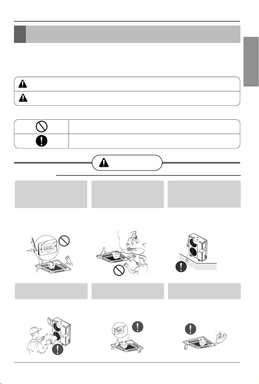
WARNING
Be sure not to do.
Be sure to follow the instruction.
Safety Precautions
■ Installation
Install the panel and the cover of
control box securely.
• There is risk of fire or
electric shock.
Always install a dedicated
circuit and breaker.
• Improper wiring or
installation may cause fire or
electric shock
Use the correctly rated breaker
or fuse.
• There is risk of fire or
electric shock.
Do not use a defective or
underrated circuit breaker. Use
this appliance on a dedicated
circuit.
• There is risk of fire or
electric shock.
For electrical work, contact the
dealer, seller, a qualified
electrician, or an Authorized
Service Center.
•
Do not disassemble or repair
the product. There is risk of
fire or electric shock.
Always ground the product.
• There is risk of fire or
electric shock.
4 Air Conditioner
Safety Precautions
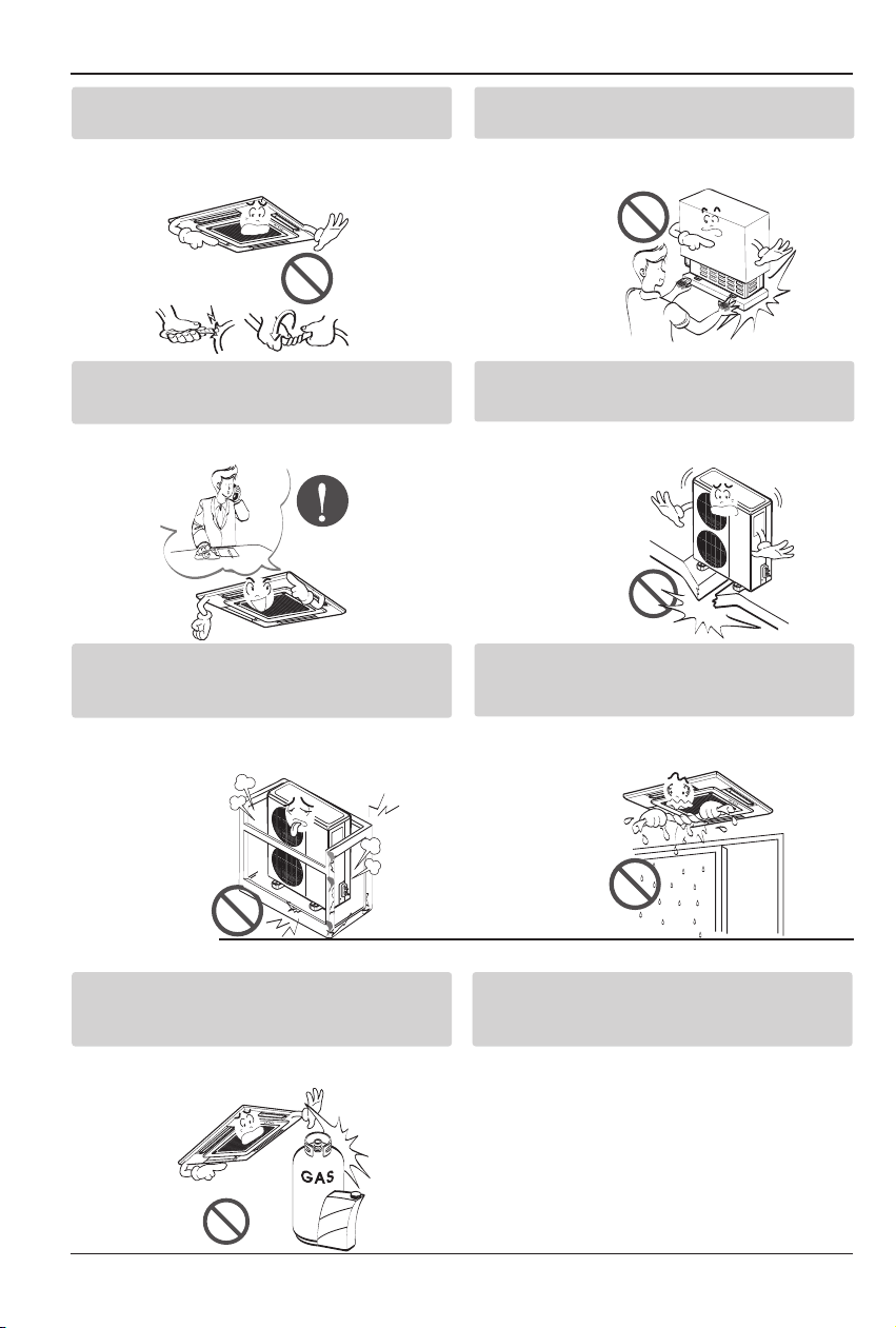
Do not modify or extend the power cable.
• There is risk of fire or electric shock.
Be cautious when unpacking and installing the
product.
•
Sharp edges could cause injury. Be especially
careful of the case edges and the fins on the
condenser and
evaporator.
For installation, always contact the dealer or an
Authorized Service Center.
• There is risk of fire, electric shock, explosion,
or injury.
Do not install the product on a defective
installation stand.
• It may cause injury, accident, or damage to
the product.
Be sure the installation area does not
deteriorate with age.
•
If the base collapses, the air conditioner could fall with
it, causing property damage, product failure, and
personal injury.
Do not let the air conditioner run for a long time when
the humidity is very high and a door or a window is
left open.
• Moisture may condense and wet or damage
furniture.
Do not store or use flammable gas or
combustibles near the product.
• There is risk of fire or failure of product.
It is recommended to install the indoor unit
into the one big space, rather than into the
some small spaces.
■ Operation
Gasolin
Installation Manual 5
ENGLISH
Safety Precautions
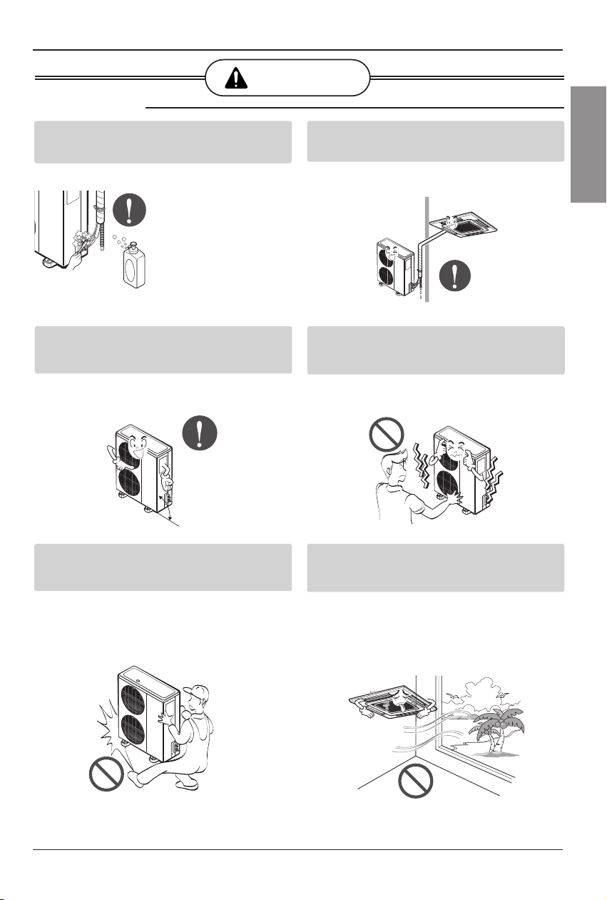
Always check for gas (refrigerant) leakage after
installation or repair of product.
• Low refrigerant levels may cause failure of
product.
Install the drain hose to ensure that water is
drained away properly.
• A bad connection may cause water leakage.
Keep level even when installing the product.
• To avoid vibration or water leakage.
Do not install the product where the noise or hot air
from the outdoor unit could damage the
neighborhoods.
• It may cause a problem for your neighbors.
Use two or more people to lift and transport the
product.
• Avoid personal injury.
Do not install the product where it will be
exposed to sea wind (salt spray) directly.
• It may cause corrosion on the product.
Corrosion, particularly on the condenser and
evaporator fins, could cause product
malfunction or inefficient operation.
CAUTION
90˚
■ Installation
6 Air Conditioner
Installation of Indoor, Outdoor Unit
Installation of Indoor, Outdoor Unit
1. Indoor unit
Cassette type
• There should not be any heat source or steam
near the unit.
• There should not be any obstacles to prevent
the air circulation.
• A place where air circulation in the room will
be good.
• A place where drainage can be easily
obtained.
• A place where noise prevention is taken into
consideration.
• Do not install the unit near the door way.
• Ensure the spaces indicated by arrows from
the wall, ceiling, or other obstacles.
• The indoor unit must keep the maintenance
space.
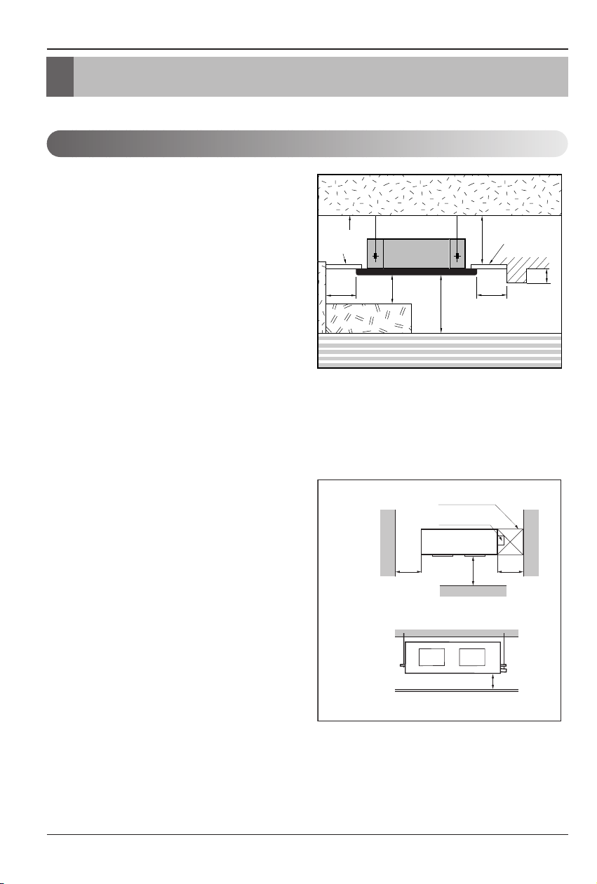
Duct type
• The place shall easily bear a load exceeding
four times the indoor unit’s weight.
• The place shall be able to inspect the unit as
the figure.
• The place where the unit shall be leveled.
• The place shall allow easy water
drainage.(Suitable dimension “H” is necessary
to get a slope to drain as figure.)
• The place shall easily connect with the
outdoor unit.
• The place where the unit is not affected by an
electrical noise.
• The place where air circulation in the room will
be good .
• There should not be any heat source or steam
near the unit
Selection of the best location
Unit:cm
Ceiling
Ceiling Board
Ceiling Board
30 or more
Above 250
330 or less
100
or more
50 or
more
50 or
more
30 or less
Floor
H
600600
Top view
(unit: mm)
Front view
Front
Inspection hole
(600X600)
Control box
1000

Installation of Indoor, Outdoor Unit
Installation Manual 7
ENGLISH
Convertible type
• There should not be any heat source or steam
near the unit.
• There should not be any obstacles to prevent
the air circulation.
• A place where air circulation in the room will
be good.
• A place where drainage can be easily
obtained.
• A place where noise prevention is taken into
consideration.
• Do not install the unit near the door way.
• Ensure the spaces indicated by arrows from
the wall, ceiling, or other obstacles.
2. Outdoor unit
• If an awning is built over the unit to prevent
direct sunlight or rain exposure, be careful
that heat radiation from the condenser is
not restricted.
• There should not be any animals or plants
which could be affected by hot air
discharged.
• Ensure the spaces indicated by arrows
from the wall, ceiling, fence or other
obstacles.
More than
20cm
More than eye-level
More than
20cm
R
R
More than
20cm
More than
20cm
(Ceiling installation)
(Floor/Wall installation)
More than
50cm
Fence or
obstacles
More than 100cm
More than 50cm
More than
30cm
More than
50cm
Sunroof
8 Air Conditioner
Installation of Indoor, Outdoor Unit
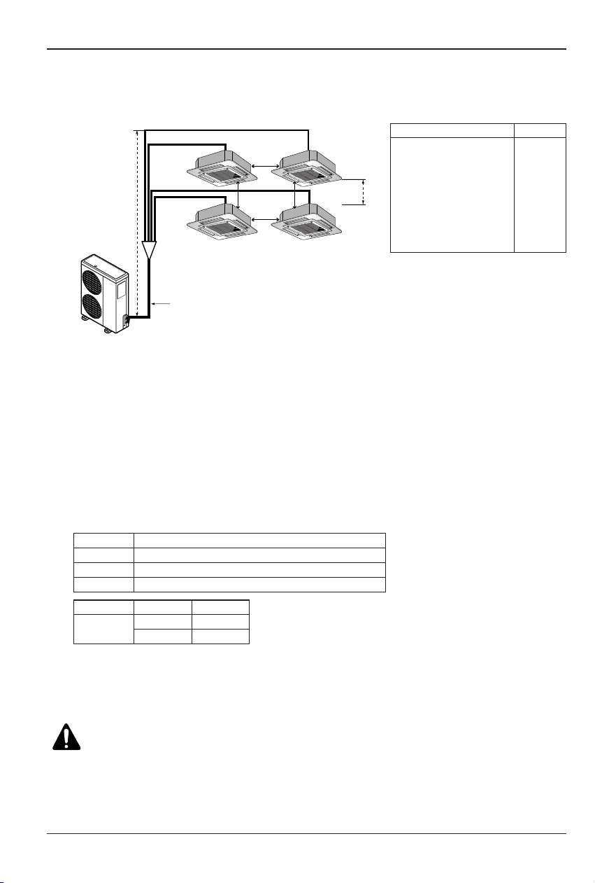
3. Piping length and the elevation
Install the branch pipe so that pipe length and difference between high and low will not exceed
below SPEC.
4. Refrigerant Additional Charging Method
For additional charging method, see below table.
<Ref. Addition charging method>
❈ (L1=Main Pipe, L2~L5 : Branch Pipe
CAUTION:
• Rated performance for refrigerant line length of:7.5m
• Capacity is based on standard length and maximum allowance length is on the
basis of reliability.
• Improper refrigerant charge may result in abnormal cycle.
• Oil trap should be installed every 10 meters.
• When installing the branch pipe, direction and angle of installation is not limited.
• Take care so that burrs and foreign material may not enter into the cutting surface when
connecting.
• Connect a gas pipe of Ø25.4 by welding the elbow in the outdoor unit and connect
remaining those by cutting or direct insertion to the diameter of pipe.
• Don’t use the liquid pipe by too bending or twisting.
Pipe Length(m)
Total(Main+Branch)
Main Pipe(L1)
Branch Pipe----Total
Each
In out (h1)
In-In (h2)
L1+L2/L3/L4/L5
Indoor-Indoor_(b)
Spec.
110
50
60
15
30
1
65
10
Branch
Main (L1)
h1
b
L2
L3
L4
L5
h2
Single (L1-30)*0.07
Duo (L1-30)*0.07+(L2+L3-20)*A
Trio (L1-30)*0.07+(L2+L3+L4-20)*A
Quartet (L1-30)*0.07+(L2+L3+L4+L5-20)*A
Branch pipe
A
Ø6.35 0.03
Ø9.52 0.05
Liquid side
Installation Manual 9
ENGLISH
• Select and mark the position for fixing bolts
and piping hole.
• Decide the position for fixing bolts slightly
tilted to the drain direction after considering
the direction of drain hose.
• Drill the hole for anchor bolt on the wall.
CAUTION:
•
This air-conditioner uses a drain pump.
• Horizontly install the unit using a
level gauge.
•
During the installation, care should be
taken not to damage electric wires.
• Thoroughly study the following installation locations:
1. In such places as restaurants and kitchens, considerable amount of oil steam and flour
adhere to the turbo fan, the fin of the heat exchanger and the drain pump, resulting in heat
exchange reduction, spraying, dispersing of water drops, drain pump malfunction, etc.
In these cases, take the following actions:
• Make sure that the ventilation fan for smoke-collecting hood on a cooking table has
sufficient capacity so that it draws oily steam which should not flow into the suction of the
air conditioner.
• Make enough distance from a cooking room to install the air conditioner in such a place
where it may not suck in oily steam.
2. Avoid installing air conditioner in such circumstances where cutting oil mist or iron powder is
in suspension in factories, etc.
3. Avoid places where inflammable gas is generated, flows in, is stored or vented.
4. Avoid places where sulfurous acid gas or corrosive gas is generated.
5. Avoid places near high frequency generators.
NOTICE
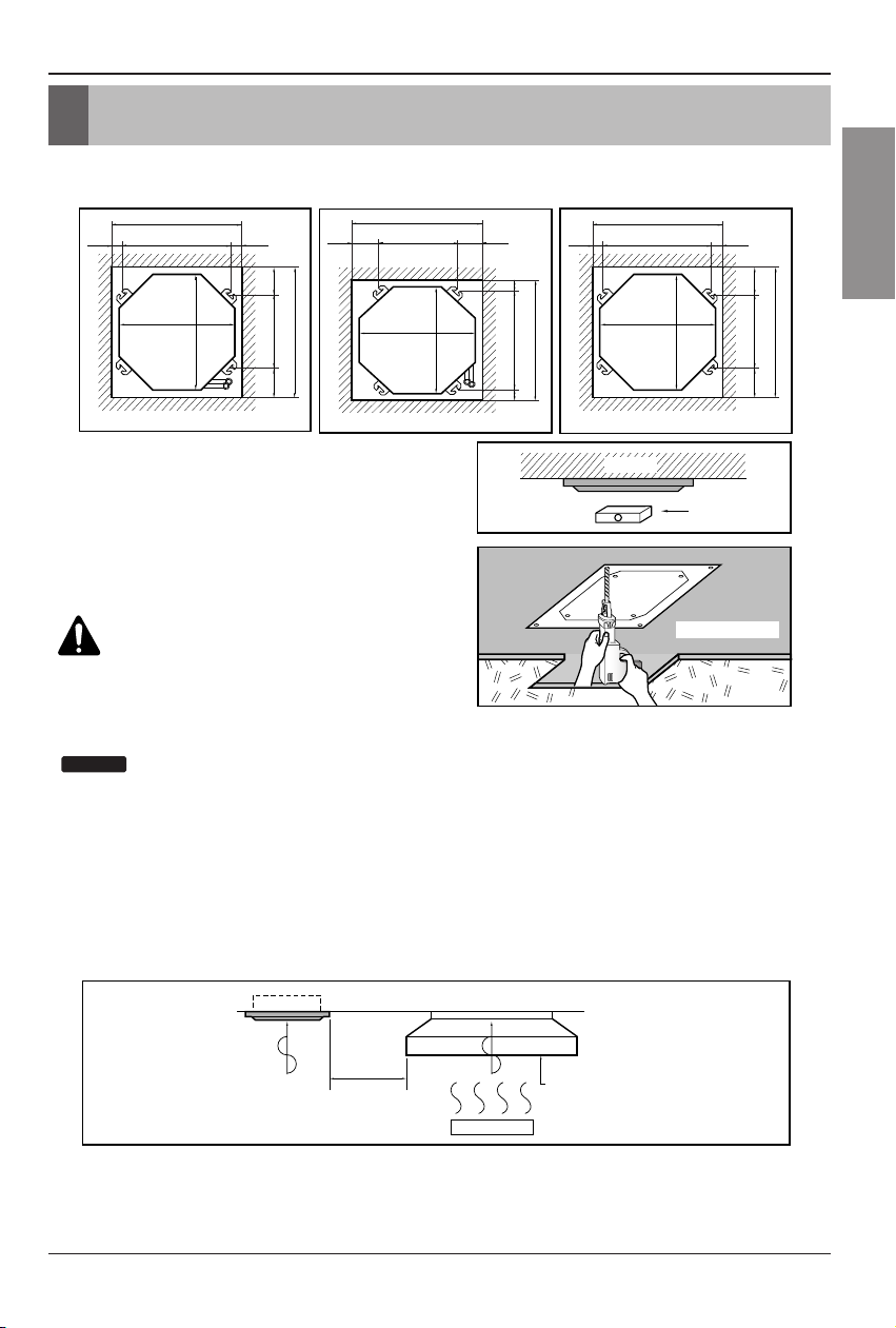
The indoor unit installation
• The dimensions of the paper model for installing are the same as those of the ceiling opening dimensions.
Ceiling board
Level gauge
Ceiling
Use the ventilation fan
for smoke-collecting
hood with sufficient
capacity.
Cooking table
Air conditioner
Take enough
distance
Unit:mm
744 Unit size
744 Unit size
658 (Hanging bolt)
6666
790 (Ceiling opening)
790 (Ceiling opening)
572(Hanging bolt)
109
109
Unit:mm
570 Unit size
570 Unit size
450 (Hanging bolt)
7575
600 (Ceiling opening)
600 (Ceiling opening)
521(Hanging bolt)
39.5
39.5
Unit:mm
840 Unit size
840 Unit size
672 (Hanging bolt)
101.5101.5
875 (Ceiling opening)
875 (Ceiling opening)
785 (Hanging bolt)
45
45
The indoor unit installation
1. Cassette type
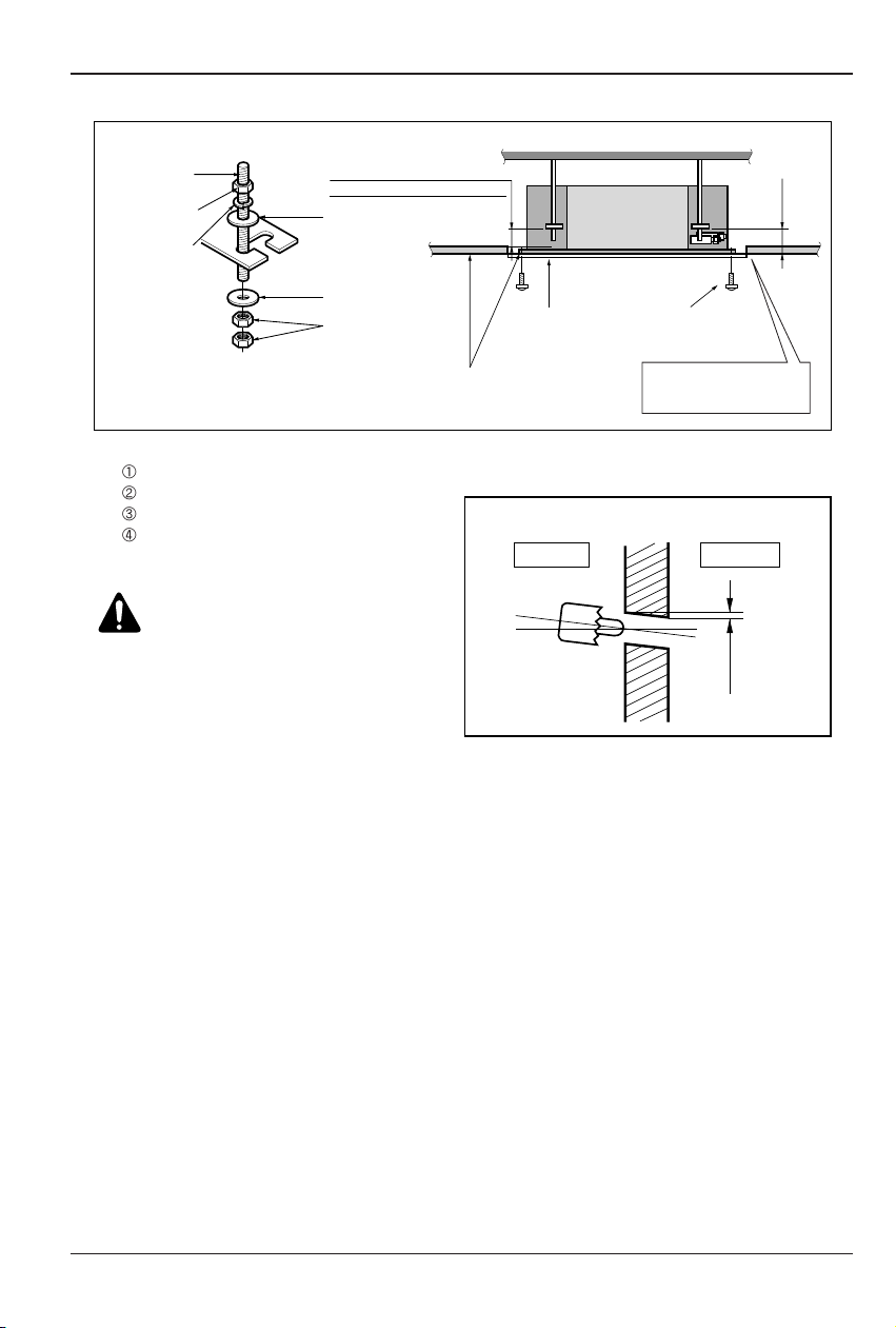
10 Air Conditioner
Wall
5~7mm
Indoor Outdoor
Set screw of
paper model (4 pieces)
Paper model
for installation
Ceiling board
150mm
Adjust the same height
Ceiling board
Ceiling
Flat washer for M10
(accessory)
Keep the length of the bolt
from the bracket to 40mm
Open the ceiling board
along the outer edge of the
paper model
Flat washer for M10
(accessory)
Hanging bolt
(W3/8 or M10)
Nut
(W3/8 or M10)
Nut
(W3/8 or M10)
Spring washer
(M10)
Air Conditioner body
The Indoor Unit Installation
• The following parts is option.
Hanging Bolt - W 3/8 or M10
Nut - W 3/8 or M10
Spring Washer - M10
Plate Washer - M10
CAUTION:
Tighten the nut and bolt
to prevent unit falling.
• Drill the piping hole on the wall slightly tilted to the
outdoor side using a Ø 70 hole-core drill.
The Indoor Unit Installation
Installation Manual 11
ENGLISH
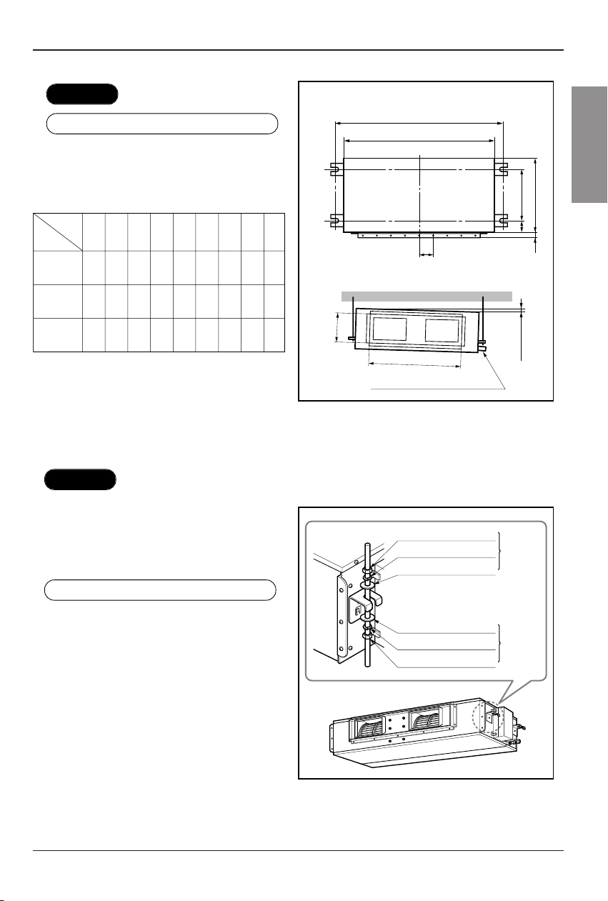
2. Duct type
• Apply a joint-canvas between the unit and
duct to absorb unnecessary vibration.
• Apply a filter Accessory at air return hole.
• Install the unit leaning to a drainage hole
side as a figure for easy water drainage.
• A place where the unit will be leveled and
that can support the weight of the unit.
• A place where the unit can withstand its
vibration.
• A place where service can be easily
perfor
med.
CASE 1
POSITION OF SUSPENSION BOLT
CASE 2
POSITION OF CONSOLE BOLT
(Unit:mm)
Drainage hole
M10 Nut
M10 SP. washer
M10 washer
X 4
X 4
(Local
supply)
X 4
M10 Nut
M10 SP. washer
M10 washer
X 4
X 4
(Local
supply)
X 4
A
B
C
D
(G)
H
I
EF
ABCDEF(G)HI
18K/24K
BTU/h
932 880 355 45.5 450 30 87 750 163
Dimension
Capacity
30K/36K
BTU/h
1232 1182 355 45.5 450 30 87 830 186
48K
BTU/h
1292 1230 477 56 590 30 120 1006 294
12 Air Conditioner
The Indoor Unit Installation
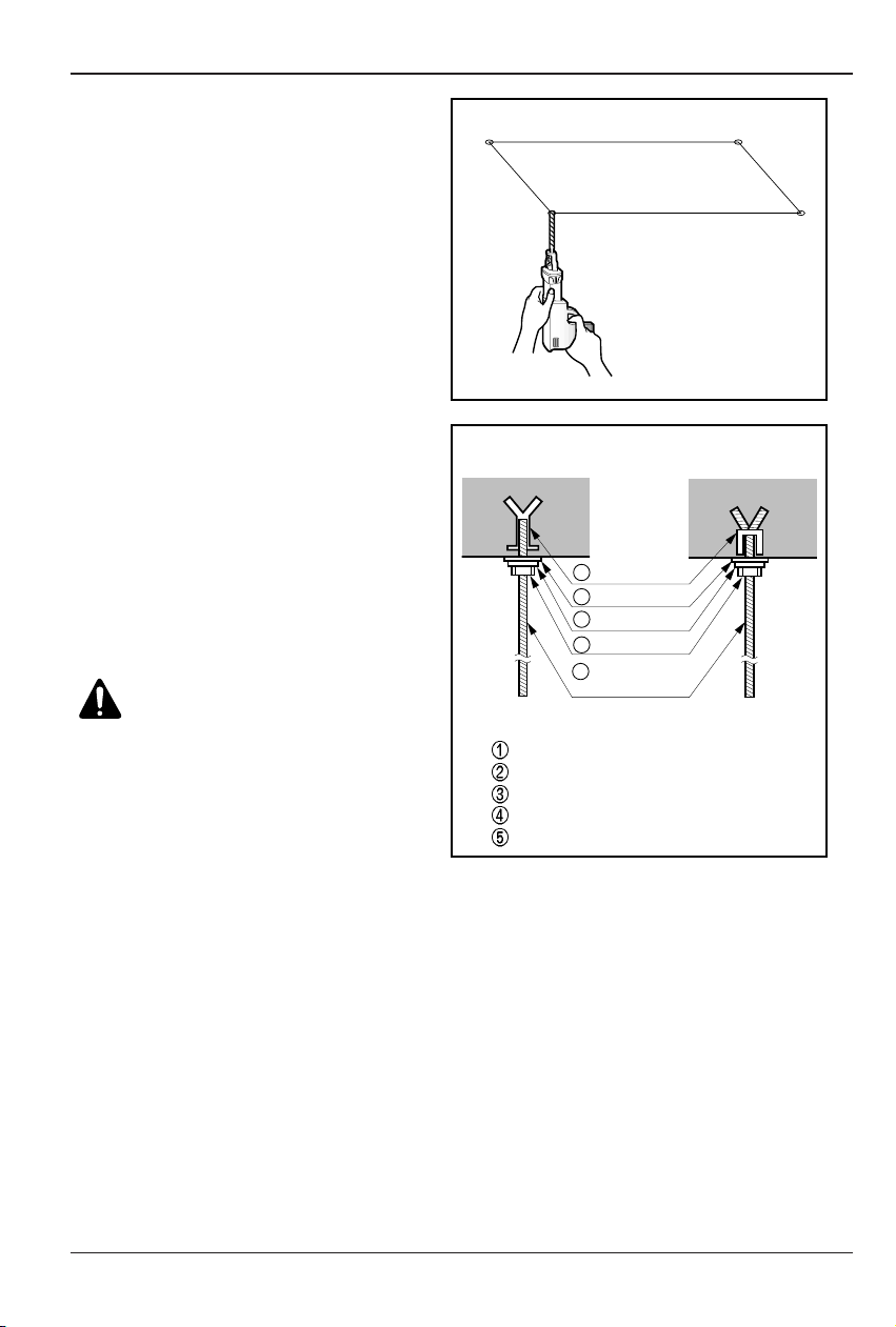
• Select and mark the position for fixing
bolts.
• Drill the hole for set anchor on the face
of ceiling.
• Insert the set anchor and washer onto
the suspension bolts for locking the
suspension bolts on the ceiling.
• Mount the suspension bolts to the set
anchor firmly.
• Secure the installation plates onto the
suspension bolts (adjust level roughly)
using nuts, washers and spring
washers
.
1 Set anchor
Old building New building
2 Plate washer
3 Spring washer
4 Nut
5 Suspension
bolts
• Local supply
Set anchor
Plate washer - M10
Spring washer - M10
Nut - W3/8 or M10
Suspension bolt - W3/8 or M10
CAUTION:
Tighten the nut and bolt top
revent unit falling.
 Loading...