


INSTALLATION MANUAL
AIR
CONDITIONER
Please read this installation manual completely before installing the product. Installation work must be performed in accordance with the national wiring standards by authorized personnel only.
Please retain this installation manual for future reference after reading it thoroughly.
TYPE : Standard inverter
<![endif]>TILI ZBEKO ‘ мова беларуская ТІЛІ ҚАЗАҚ УКРАÏНСЬКА ЯЗЫК РУССКИЙ ENGLISH
|
|
|
|
|
|
|
|
|
|
|
|
|
|
|
|
|
|
|
|
|
|
|
|
|
|
|
|
|
|
|
|
|
|
|
|
|
|
|
|
|
|
|
|
|
|
|
|
|
|
www.lg.com |
|
MFL69190205 |
|
|
|
|
|
|
|
|
|
|
|
|
|
|
|
|
|
||||||||||||||||||||||||||||||||
|
|
|
|
|
|
|
|
|
|
|
|
|
|
|
|
|
|
|
|
|
|
|
|
|
|
|
|
|
|
|
|
|
|
|
Copyright © 2015 - 2019 LG Electronics Inc. All Rights Reserved. |
|||||||||||||||
|
Rev.01_051719 |
|
|
|
|
|
|
|
|
|
|
|
|
|
|
|
|
|
|
|
|
|
|
|
|
|
|
|
|
|
|
|
|
|
|
|||||||||||||||
Table of contents
TABLE OF CONTENTS
3SAFETY PRECAUTIONS
6INSTALLATION OF OUTDOOR UNIT
9Night Silent Operation setting
10 WIRING CONNECTION
10 Electrical Wiring
10 Connecting Cables between Indoor Unit and Outdoor Unit
12Connecting the cable to Outdoor Unit
13CONNECTING PIPES
13Preparation of Piping
14Connecting the pipes to the Outdoor unit
16Forming the piping
17LEAKAGE TEST AND EVACUATION
17Preparation
17Leakage test
18Evacuation
19TEST RUNNING
21 FUNCTION
21Forced Cooling Operation
22SELF-DIAGNOSIS FUNCTION
22Error Indicator (Outdoor)
23INSTALLATION GUIDE AT THE SEASIDE
2 Air Conditioner

Safety Precautions
Safety Precautions
To prevent the injury of the user or other people and property damage, the following instructions must be followed.
νBe sure to read before installing the air conditioner.
νBe sure to observe the cautions specified here as they include important items related to safety.
νIncorrect operation due to ignoring instruction will cause harm or damage. The seriousness is classified by the following indications.
!WARNING This symbol indicates the possibility of death or serious injury.
!CAUTION This symbol indicates the possibility of injury or damage to properties only.
νThe meanings of the symbols used in this manual are as shown below.
Be sure not to do.
Be sure to follow the instruction.
! WARNING
Installation
•Always perform grounding.
-Otherwise, it may cause electrical shock.
•Don’t use a power cord, a plug or a loose socket which is damaged.
-Otherwise, it may cause a fire or electrical shock.
•For installation of the product, always contact the service center or a professional installation agency.
-Otherwise, it may cause a fire, electrical shock, explosion or injury.
•Securely attach the electrical part cover to the indoor unit and the service panel to the outdoor unit.
-If the electrical part cover of the indoor unit and the service panel of the outdoor unit are not attached securely, it could result in a fire or electric shock due to dust, water, etc.
•Always install an air leakage breaker and a dedicated switching board.
-No installation may cause a fire and electrical shock.
•Do not keep or use flammable gases or combustibles near the air conditioner.
-Otherwise, it may cause a fire or the failure of product.
•Ensure that an installation frame of the outdoor unit is not damaged due to use for a long time.
-It may cause injury or an accident.
•Do not disassemble or repair the product randomly.
-It will cause a fire or electrical shock.
•Use a vacuum pump or Inert (nitrogen) gas when doing leakage test or air purge. Do not compress air or Oxygen and do not use Flammable gases. Otherwise, it may cause fire or explosion.
<![endif]>ENGLISH
Installation Manual 3

Safety Precautions
-There is the risk of death, injury, fire or explosion.
•Do not install the product at a place that there is concern of falling down.
-Otherwise, it may result in personal injury.
•Use caution when unpacking and installing.
-Sharp edges may cause injury.
Operation
•Do not share the outlet with other appliances.
-It will cause an electric shock or a fire due to heat generation.
•Do not use the damaged power cord.
-Otherwise, it may cause a fire or electrical shock.
•Do not modify or extend the power cord randomly.
-Otherwise, it may cause a fire or electrical shock.
•Take care so that the power cord may not be pulled during operation.
-Otherwise, it may cause a fire or electrical shock.
•Unplug the unit if strange sounds, smell or smoke comes from it.
-Otherwise, it may cause electrical shock or a fire.
•Keep the flames away.
-Otherwise, it may cause a fire.
•Take the power plug out if necessary, holding the head of the plug and do not touch it with wet hands.
-Otherwise, it may cause a fire or electrical shock.
•Do not use the power cord near the heating tools.
-Otherwise, it may cause a fire and electrical shock.
•Do not open the suction inlet of the indoor/outdoor unit during operation.
-Otherwise, it may electrical shock and failure.
•Do not allow water to run into electrical parts.
-Otherwise, it may cause the failure of machine or electrical shock.
•Hold the plug by the head when taking it out.
-It may cause electric shock and damage.
•Never touch the metal parts of the unit when removing the filter.
-They are sharp and may cause injury.
•Do not step on the indoor/outdoor unit and do not put anything on it.
-It may cause an injury through dropping of the unit or falling down.
•Do not place a heavy object on the power cord.
-Otherwise, it may cause a fire or electrical shock.
•When the product is submerged into water, always contact the service center.
-Otherwise, it may cause a fire or electrical shock.
•Take care so that children may not step on the outdoor unit.
-Otherwise, children may be seriously injured due to falling down.
4 Air Conditioner
Safety Precautions
! CAUTION
Installation
•Install the drain hose to ensure that drain can be securely done.
-Otherwise, it may cause water leakage.
•Install the product so that the noise or hot wind from the outdoor unit may not cause any damage to the neighbors.
-Otherwise, it may cause dispute with the neighbors.
•Always inspect gas leakage after the installation and repair of product.
-Otherwise, it may cause the failure of product.
•Keep level parallel in installing the product.
-Otherwise, it may cause vibration or water leakage.
•Means for disconnection must be incorporated in the fixed wiring in accordance with the wiring rules.
Operation
•Avoid excessive cooling and perform ventilation sometimes.
-Otherwise, it may do harm to your health.
•Use a soft cloth to clean. Do not use wax, thinner or a strong detergent.
-The appearance of the air conditioner may deteriorate, change color or develop surface flaws.
•Do not use an appliance for special purposes such as preserving animals vegetables, precision machine or art articles.
-Otherwise, it may damage your properties.
•Do not place obstacles around the flow inlet or outlet.
-Otherwise, it may cause the failure of appliance or an accident.
<![endif]>ENGLISH
Installation Manual 5
Installation of Outdoor Unit
Installation of Outdoor Unit
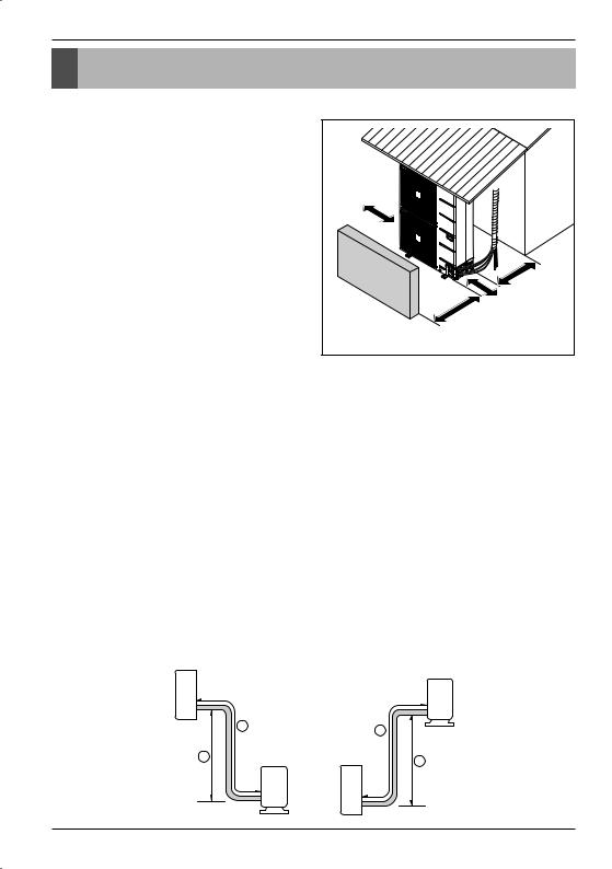
1. Installation Places
•If an awning is built over the unit to prevent direct sunlight or rain exposure, make sure that heat radiation from the condenser is not restricted.
•Ensure that the spaces indicated by arrows around front, back and side of the unit.
•Do not place animals and plants in the path of the warm air.
•Take the air conditioner weight into account and select a place where noise and vibration are minimum.
•Select a place so that the warm air and noise from the air conditioner do not disturb neighbors.
|
Sunroof |
More than |
|
300 mm |
|
Fence |
More than |
300 mm |
|
|
|
or |
|
obstacles |
More than 600 mm |
|
|
|
More than 700 mm |
|
Unit : mm |
2. Piping length and the elevation
ν Single Operation
|
|
Pipe Size |
Length A(m) |
Elevation B(m) |
Additional |
||||
Model |
Capacity |
mm(inch) |
refrigerant |
||||||
|
|
|
|
||||||
|
|
Gas |
Liquid |
Standard |
Max. |
Standard |
Max. |
(g/m) |
|
UU18W |
5 kW |
Ø 12.7(1/2) |
Ø 6.35(1/4) |
7.5 |
40 |
5 |
30 |
20 |
|
UU24W |
7 kW |
Ø 15.88(5/8) |
Ø 9.52(3/8) |
7.5 |
50 |
5 |
30 |
40 |
|
|
|
|
|
|
|
|
|
|
|
UU30W |
8 kW |
Ø 15.88(5/8) |
Ø 9.52(3/8) |
7.5 |
50 |
5 |
30 |
40 |
|
|
|
|
|
|
|
|
|
|
|
UU36W/UU37W |
10 kW |
Ø 15.88(5/8) |
Ø 9.52(3/8) |
7.5 |
50 |
5 |
30 |
40 |
|
|
|
|
|
|
|
|
|
|
|
UU42W/UU43W |
12.5 kW |
Ø 15.88(5/8) |
Ø 9.52(3/8) |
7.5 |
75 |
5 |
30 |
40 |
|
UU48W/UU49W |
14 kW |
Ø 15.88(5/8) |
Ø 9.52(3/8) |
7.5 |
75 |
5 |
30 |
40 |
|
UU60W/UU61W |
15 kW |
Ø 15.88(5/8) |
Ø 9.52(3/8) |
7.5 |
75 |
5 |
30 |
40 |
|
If installed tube is shorter than 7.5 m, additional charging is not necessary.
Additional Refrigerant = (A-7.5)xAdditional refrigerant (g)
Indoor unit
Outdoor unit
A
B |
Outdoor unit |
|
A |
Indoor unit |
B |
|
6 Air Conditioner

Installation of Outdoor Unit
ν Synchro Operation
Install the branch pipe so that pipe length and difference between high and low will not exceed below Spec.
|
L2 |
Branch |
|
[Unit : m] |
|
L3 |
|
Pipe Length & Height |
Spec(MAX.) |
|
|
A |
Total(L1+L2+L3+L4+L5) |
80 |
|
|
|
||
|
L4 |
|
Main Pipe(L1) |
45 |
|
|
H2 |
|
|
|
|
|
40 |
|
H1 |
L5 |
|
Branch Pipe (L2+L3+L4+L5) |
|
|
|
A |
Each |
15 |
|
|
|
|
|
|
|
|
Indoor-Outdoor (H1) |
30 |
|
Remote |
|
Indoor-Indoor (H2) |
1 |
|
Controller |
|
|
|
|
|
|
(L1+L2),(L1+L3),(L1+L4),(L1+L5) |
70 |
|
L1 |
|
A |
10 |
|
|
|
•When installing the branch pipe, direction and angle of installation is not limited.
•Take care so that burrs and foreign material may not enter into the cutting surface when connecting.
•Connect remaining those by cutting or direct insertion to the diameter of pipe.
ν Refrigerant Additional Charging Method |
|
For additional charging method, see below table. |
|
Indoor Unit |
Refrigerant Additional charging (g) |
Duo |
Refrigerant = (L1-b)xB+(L2+L3)xC |
Trio |
Refrigerant = (L1-b)xB+(L2+L3+L4)xC |
Quartet |
Refrigerant = (L1-b)xB+(L2+L3+L4+L5)xC |
Pipe Size |
C |
mm(inch) |
(g/m) |
Ø 6.35(1/4) |
35 |
Ø 9.52(3/8) |
40 |
Model |
b |
B |
|
(m) |
(g/m) |
||
|
|||
UU42W/UU43W |
|
|
|
UU48W/UU49W |
7.5 |
40 |
|
UU60W/UU61W |
|||
|
|
NOTICE
b : Rated performance for refrigerant line length.
C : Additional charging Refrigerant of Branch Liquid Pipe. B : Additional charging Refrigerant of Main Liquid Pipe.
!CAUTION
•Capacity is based on standard length and maximum allowance length is on the basis of reliability.
•Improper refrigerant charge may result in abnormal cycle.
<![endif]>ENGLISH
Installation Manual 7
Installation of Outdoor Unit
3. Synchro Combination table
|
|
|
|
|
|
|
|
|
|
|
|
|
|
Possible combination of indoor units |
|
|
|
|
|
|
|
|
|
||||||||||||||||||||||
|
|
|
|
|
|
|
|
|
|
|
|
|
|
|
|
|
|
|
|
Synchro |
|
|
|
|
|
|
|
|
|
|
|
|
|
|
|
|
|
|
|
||||||
|
|
|
|
|
|
|
|
Duo |
|
|
|
|
|
|
|
|
|
Trio |
|
|
|
|
|
|
|
|
|
|
Quartet |
|
|
|
|
||||||||||||
IDU : INDOOR UNIT |
|
|
|
|
|
|
|
|
|
|
|
|
|
|
|
|
|
|
|
|
|
|
|
|
|
|
|
|
|
|
|
|
|
|
|
|
|
|
|
|
|
|
|
|
|
ODU : OUTDOOR UNIT |
|
|
|
|
|
|
|
|
|
|
|
|
|
|
|
|
|
|
|
|
|
|
|
|
|
|
|
|
|
|
|
|
|
|
|
|
|
|
|
|
|
|
|
|
|
BD : BRANACH |
|
|
|
|
|
|
ODU |
|
|
|
|
|
|
|
|
|
|
ODU |
|
|
|
|
|
|
|
|
|
|
|
|
ODU |
|
|
|
|
|
|||||||||
DISTRIBUTOR UNIT |
|
|
|
|
|
|
|
|
|
|
|
|
|
|
|
|
|
|
|
|
|
|
|
BD |
|
|
|
|
|
|
|
|
|
|
|
|
|
|
|
|
|
|
|
||
|
|
|
|
|
|
|
BD |
|
|
|
|
|
|
|
|
|
|
|
|
|
|
|
|
|
|
|
|
|
|
|
|
|
|
|
|
BD |
|
|
|
|
|||||
REMO : WIRED |
|
|
IDU |
|
|
|
|
IDU |
|
|
|
IDU |
|
IDU |
|
IDU |
|
|
|
IDU |
|
|
IDU |
IDU |
|
IDU |
|
||||||||||||||||||
REMOTE |
|
|
REMO |
|
|
|
|
|
|
|
|
|
|
REMO |
|
|
|
|
|
|
|
|
|
|
|
|
|
|
|
|
|
|
|
|
|
|
|
|
|
|
|
||||
|
|
|
|
|
|
|
|
|
|
|
|
|
|
|
|
|
|
|
|
|
|
|
|
|
REMO |
|
|
|
|
|
|
|
|
|
|
|
|
||||||||
CONTROLLER |
|
|
|
|
|
|
|
|
|
|
|
|
|
|
|
|
|
|
|
|
|
|
|
|
|
|
|
|
|
|
|
|
|
|
|
|
|
|
|
|
|
|
|
|
|
|
|
|
|
|
|
|
|
|
|
|
|
|
|||||||||||||||||||||||||||||||||
MODEL |
Cassette |
Duct |
|
Ceiling |
Cassette |
|
Duct |
Ceiling |
Cassette |
|
Duct |
|
Ceiling |
||||||||||||||||||||||||||||||||
|
|
|
|
|
|
|
|
|
|
|
|
Suspended |
|
|
|
|
|
|
|
|
|
|
|
|
Suspended |
|
|
|
|
|
|
|
|
|
|
|
|
Suspended |
|||||||
UU42W/UU43W |
CT24 NP2R0 |
CB24 NH2R0 |
|
CV24 NJ2R0 |
CT18 NQ2R0 |
CB18 NH2R0 |
CV18 NJ2R0 |
CT12 NR2R0 |
- |
|
|
- |
|
||||||||||||||||||||||||||||||||
UU48W/UU49W |
CT24 NP2R0 |
CB24 NH2R0 |
|
CV24 NJ2R0 |
CT18 NQ2R0 |
CB18 NH2R0 |
CV18 NJ2R0 |
CT12 NR2R0 |
- |
|
|
- |
|
||||||||||||||||||||||||||||||||
UU60W/UU61W |
UT30WNP2R0 |
UB30 NG2R0 |
|
UV30 NJ2R0 |
CT18 NQ2R0 |
CB18 NH2R0 |
CV18 NJ2R0 |
CT12 NR2R0 |
- |
|
|
- |
|
||||||||||||||||||||||||||||||||
Applied |
Bdunit |
|
|
|
PMUB11A |
|
|
|
|
|
PMUB111A |
|
|
|
|
|
|
|
PMUB1111A |
|
|||||||||||||||||||||||||
Accessi |
Simple central |
|
|
|
|
|
|
|
|
|
|
|
|
|
|
|
PQCSZ250S0 |
|
|
|
|
|
|
|
|
|
|
|
|
|
|
|
|
||||||||||||
ries |
controller** |
|
|
|
|
|
|
|
|
|
|
|
|
|
|
|
|
|
|
|
|
|
|
|
|
|
|
|
|
|
|
|
|||||||||||||
|
|
|
|
|
|
|
|
|
|
|
|
|
|
|
|
|
|
|
|
|
|
|
|
|
|
|
|
|
|
|
|
|
|
|
|
|
|
|
|
|
|
|
|
||
|
|
|
|
|
|
|
|
|
|
|
|
|
|
|
|
|
|
|
|
|
|
|
|
|
|
|
|
|
|
|
|
|
|
|
|
|
|
|
|
|
|
|
|
|
|
NOTICE
**When using synchro operation,
-Do not use wireless remote controller.
-Use only one wired remote controller in the indoor units.
-Use Simple central controller "PQCSZ250S0" only.
4. Outdoor Unit PCB Setting Procedure For Simultaneous Operation System
1.SW01N (PIP SW2) Setting
Set the SW01N (PIP SW2) as below Table ( )
2.Auto Addressing Method
Addressing work assigns address to each indoor unit. When firstly installing product or replacing the indoor unit PCB. Auto Addressing work should be done for simultaneous operation.
ηWork procedure
1)Set SW01N (PIP SW2) correctly.
2)Turn on main power.
3)Press the SW02N (SW01B) for about 3 seconds within 3 minutes After main power on.( )
B  SW02N
SW02N
<![endif]>SW01N


 6
6
A
A
|
<![if ! IE]> <![endif]>LED01H |
|
LED01M |
|
LED02M |
|
<![if ! IE]> <![endif]>DIP SW2 |
|
<![if ! IE]> <![endif]>SW01B |
MAIN PCB |
B |
|
|
UU42W/48W/60W |
|
 LED01G LED02G
MAIN PCB
UU43W/49W/61W
8 Air Conditioner
 Loading...