


60 0P PF F9 9
Table of contents
 Loading...
LG Electronics 60 0P PF F9 9, 50 0P PF F9, 52 2L LF F6, 52 2L LY Y9, 47 7L LY Y9 User Manual
...
Please read this manual carefully before operating
your set.
Retain it for future reference.
Record model number and serial number of the set.
See the label attached on the back cover and quote
this information to your dealer when you require
service.
LCD TV PLASMA TV
OWNER’S MANUAL
LCD TV MODELS
3377 LLFF66
**
3377 LLYY99
**
4422 LLFF66
**
4422 LLYY99
**
4477 LLFF66
**
4477 LLYY99
**
5522 LLFF66**5522 LLYY99
**
3377 LLFF77 **
4422 LLFF77 **
PLASMA TV MODELS
5500 PPFF99
**
6600 PPFF99
**
Trade Mark of the DVB Digital Video
Broadcasting Project (1991 to 1996)
IIDD NNuummbbeerr(( ss))::
4560: 37LY95 4536: 47LF65
4534: 42LY95 4604: 37LY96
4558: 47LY95 4606: 47LY96
4537: 42LF65 4608: 37LF66
4605: 42LY96 4610: 47LF66
4607: 52LY96 4612: 52LF66
4609: 42LF66 4614: 50PF96
4611: 52LF65 4724: 37LF75
4725: 42LF75 4911: 42LY99
4615: 60PF96 4965: 50PF95(50PF95-ZJ)
4551: 60PF95 4613: 50PF95 (50PF95-ZA)
4535: 37LF65 5110: 37LF76
5111: 42LF76
Downloaded From TV-Manual.com Manuals

Downloaded From TV-Manual.com Manuals
1
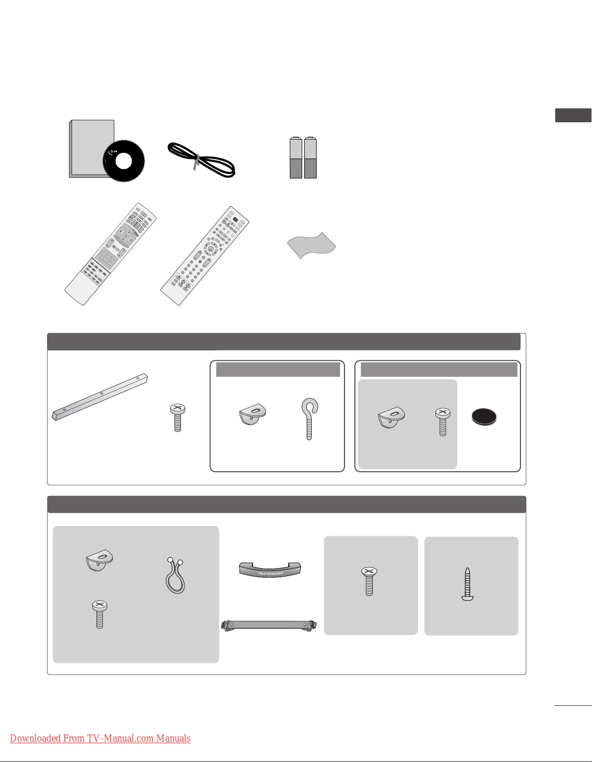
ACCESSORIES
ACCESSORIES
Ensure that the following accessories are included with your TV. If an accessory is missing, please contact the
dealer where you purchased the product.
Owner's
Manual
Owner’s manual
Owner’s Manual
Batteries
D/A
INPUT
VOL
LIST
FAV
PR
POWER
1 2 3
456
78
0
9
UPDATE INDEX
SIZE
G
UIDE
I/II
MENU
MUTE
Q.VIEW
EXIT
VCR
TV
DVD
TEXT
B
A
C
K
PICTURE
SLEEP
RATIO
TIME
REVEAL
?
HOLD
i
OK
SUBTITLE
TV/RADIO
SOUND
INFO i
Remote Control
Power Cord
2- TV Brackets
2- Wall Brackets
2-bolts
Twister Holder
Arrange the wires
with the twister
holder.
LLCCDD TTVV mmooddeellss
Polishing Cloth
Polish the screen with the cloth.
Slightly wipe stained spot on the exterior
only with the cleansing cloths for the product exterior if there is stain or fingerprint
on surface of the exterior.
Do not wipe roughly when removing stain.
Please be cautious of that excessive power
may cause scratch or discoloration.
OK
INPUT
MODE
TV
D/A
DVD
EXIT
VOL PR
GUIDE
B
AC
K
MENU
RATIO
I/II
VCR
POWER
123
456
789
0
Q.VIEW
LIST
INDEX
S
LE
E
P
HOLD
R
E
V
E
A
L
?
SUBTITLE
TEXT
INPUT
BRIGHT
MUTE
TV/RADIO
UPDATE
SIMPLINK
INFO i
FAV
TIM
E
or
4-bolts for stand assembly
Refer to p. 10
3377”” oonnll yy
1-screw for stand fixing
Refer to p. 10
3377LLFF 77**oonnll yy
Cable Management
or
5500PP FF 99
**
oonnllyy
2-Wall brackets
2-eye-bolts
Two rubber caps
Refer to p. 15
2- TV Brackets
2- Wall Brackets
Plasma
TTVV mmooddeellss
One desk-type stand fixture
protection cover
Refer to p. 15
3-bolts
Refer to p. 15
■
This feature is not available for all models.
■
This feature is not available for all models.
6600PP FF 99
**
oonnllyy
■
This feature is not available
for all models.
2-bolts
Downloaded From TV-Manual.com Manuals

2
CONTENTS
CONTENTS
ACCESSORIES
. . . . . . . . . . . . . . . . . . . . . . . . . . . . . . . . . . . . . . . . . . . . .
1
PREPARATION
Front Panel Controls....................................................... 4
Back Panel Information .................................................. 7
Stand installation
............................................................. 10
ATTACHING THE TV TO A DESK................................10
Attaching the TV to a wall ............................................ 11
Back Cover for Wire Arrangement............................. 12
Desktop Pedestal Installation ...................................... 15
Wall Mount: Horizontal installation ........................... 15
Antenna Connection...................................................... 16
EXTERNAL EQUIPMENT SETUP
HD Receiver Setup . . . . . . . . . . . . . . . . . . . . . . . . . . . . . . . . . . . . . . . . . . 17
DVD Setup . . . . . . . . . . . . . . . . . . . . . . . . . . . . . . . . . . . . . . . . . . . . . . . . . . . . . . . . 20
Insertion of CI module
. . . . . . . . . . . . . . . . . . . . . . . . . . . . . . . . . . . . . . . 22
VCR Setup . . . . . . . . . . . . . . . . . . . . . . . . . . . . . . . . . . . . . . . . . . . . . . . . . . . . . . . .23
Digital Audio Out Setup
. . . . . . . . . . . . . . . . . . . . . . . . . . . . . . . . . . . . 25
Other A/V Source Setup . . . . . . . . . . . . . . . . . . . . . . . . . . . . . . . . . . . . 26
PC Setup
. . . . . . . . . . . . . . . . . . . . . . . . . . . . . . . . . . . . . . . . . . . . . . . . . . . . . . . . . . 27
- Screen Setup for PC Mode
. . . . . . . . . . . . . . . . . . . . . . . . . . 30
WATCHING TV / PROGRAMME CONTROL
Remote Control Key Functions . . . . . . . . . . . . . . . 34
Turning on the TV . . . . . . . . . . . . . . . . . . . . . . . . .38
Programme Selection . . . . . . . . . . . . . . . . . . . . . . 39
Volume Adjustment . . . . . . . . . . . . . . . . . . . . . . . 39
On Screen Menus Selection and Adjustment . . . . 40
Auto Programme Tuning (In Digital Mode) . . . . . 41
Manual Programme Tuning (In Digital Mode) . . . 42
Programme Edit (In Digital Mode) . . . . . . . . . . . . 43
5V antenna Power (In Digital Mode only) . . . . . . 45
Software Update (In Digital Mode only) . . . . . . . 46
Diagnostics (In Digital Mode only) . . . . . . . . . . . 47
CI Information (In Digital Mode only) . . . . . . . . . 48
Auto Programme Tuning (In Analogue Mode) . . . . 49
Manual Programme Tuning (In Analogue Mode)
. . . . 50
Fine Tuning (In Analogue Mode) . . . . . . . . . . . . . 51
Assigning a Station Name (In Analogue Mode)
. . . . . 51
Programme Edit (In Analogue Mode)
. . . . . . . . . . . . 52
Calling the Programme Table . . . . . . . . . . . . . . . . 54
Input Source Selection . . . . . . . . . . . . . . . . . . . . . 55
Index . . . . . . . . . . . . . . . . . . . . . . . . . . . . . . . . . .55
SIMPLINK . . . . . . . . . . . . . . . . . . . . . . . . . . . . . . . 56
PICTURE CONTROL
EPG (Electronic programme guide) (In Digital Mode)
- Switch on/off EPG . . . . . . . . . . . . . . . . . . . . 58
- Select a programme . . . . . . . . . . . . . . . . . . . 58
-
Button function in NOW/NEXT guide mode
. . . . 59
-
Button function in 8 days guide mode
. . . . . . . . 59
-
Button function in date change mode
. . . . . . . . . 59
-
Button function in extended description box
. . . . 60
-
Button function in record/remind setting mode
. . 60
-
Button function in timer list mode
. . . . . . . . . . . 60
Picture Size (Aspect Ratio) Control . . . . . . . . . . . 61
Preset Picture Settings
- Picture Mode-Preset
. . . . . . . . . . . . . . . . . . . . . . . . . . . . . . . . . . . . 63
-
Auto Colour Tone Control (Warm/Medium/Cool)
. . . 64
Manual Picture Adjustment
- Picture Mode-User option . . . . . . . . . . . . . . . 65
- Colour Tone - User option . . . . . . . . . . . . . . .66
XD - Picture Improvement Technology . . . . . . . . . . . . 67
XD Demo . . . . . . . . . . . . . . . . . . . . . . . . . . . . . . . . . 68
TruMotion Demo . . . . . . . . . . . . . . . . . . . . . . . . . . . 68
Advanced - Cinema . . . . . . . . . . . . . . . . . . . . . . . . . 69
Advanced - TruMotion . . . . . . . . . . . . . . . . . . . . . . 69
Advanced - Black(Darkness) Level . . . . . . . . . . . . . 70
Picture Reset . . . . . . . . . . . . . . . . . . . . . . . . . . . . . 71
Image Sticking Minimization(ISM) Method . . . . . . . . . 72
Low-Power Picture Mode . . . . . . . . . . . . . . . . . . . . 73
Downloaded From TV-Manual.com Manuals

3
CONTENTS
SOUND & LANGUAGE CONTROL
Auto Volume Leveler . . . . . . . . . . . . . . . . . . . . . . . 74
Preset Sound Settings - Sound Mode . . . . . . . . . 75
Sound Setting Adjustment - User Mode . . . . . . . . . 76
Balance . . . . . . . . . . . . . . . . . . . . . . . . . . . . . . . . . . 77
TV Speakers On/ Off Setup . . . . . . . . . . . . . . . . . 78
Selecting digital audio out . . . . . . . . . . . . . . . . . . 79
I/II
-
Stereo/Dual Reception (In Analogue Mode Only)
. . . .80
-
NICAM Reception (In Analogue Mode Only) . . . . . .
81
- Speaker Sound Output Selection . . . . . . . . . 81
On-Screen Menu Language/Country Selection
. . . . . 82
Language selection (In Digital Mode only) . . . . . . 83
TIME SETTING
Clock Setup . . . . . . . . . . . . . . . . . . . . . . . . . . . . . . 84
Auto On/ Off Timer Setting . . . . . . . . . . . . . . . . . 85
Auto Shut-off Setting . . . . . . . . . . . . . . . . . . . . . . . 86
Time Zone Setup . . . . . . . . . . . . . . . . . . . . . . . . . . 87
Sleep Timer Setting . . . . . . . . . . . . . . . . . . . . . . . . 87
PARENTAL CONTROL / RATINGS
Set Password & Lock System . . . . . . . . . . . . . . . . 88
Parental Control . . . . . . . . . . . . . . . . . . . . . . . . . . . 89
TELETEXT
Switch on/off . . . . . . . . . . . . . . . . . . . . . . . . . . . . . 90
SIMPLE Text . . . . . . . . . . . . . . . . . . . . . . . . . . . . . . 90
TOP Text . . . . . . . . . . . . . . . . . . . . . . . . . . . . . . . . 90
FASTEXT . . . . . . . . . . . . . . . . . . . . . . . . . . . . . . . . . 91
Special Teletext Functions . . . . . . . . . . . . . . . . . . . 91
DIGITAL TELETEXT
Teletext within Digital Service . . . . . . . . . . . . . . . 92
Teletext in Digital Service
. . . . . . . . . . . . . . . . . . 92
APPENDIX
Troubleshooting . . . . . . . . . . . . . . . . . . . . . . . . . . . 93
Maintenance . . . . . . . . . . . . . . . . . . . . . . . . . . . . . 95
Product Specifications . . . . . . . . . . . . . . . . . . . . . 96
Programming the Remote Control . . . . . . . . . . . . 98
IR Codes . . . . . . . . . . . . . . . . . . . . . . . . . . . . . . . . 102
External Control Device Setup . . . . . . . . . . . . . . 104
Downloaded From TV-Manual.com Manuals
4
PREPARATION
PREPARATION
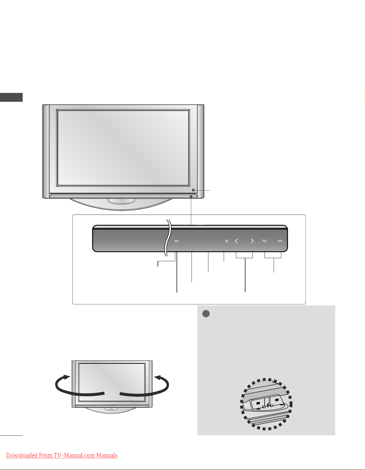
FRONT PANEL CONTROLS
Plasma TV Models: 50PF9*, 60PF9
*
A
This is a simplified representation of the front panel. Here shown may be somewhat different from your TV.
A
If your product has a protection film attached, remove the film and then wipe the product with a polishing
cloth.
SWIVEL STAND
(Only
PLASMA TV MODELS
)
After installing the TV, you can adjust the TV set
manually to the left or right direction by 20 degrees
to suit your viewing position.
NOTE
!
GG
Before adjusting the angle, you must
remove the cable management and
loosen (to the left) the shaft bolt on the
middle of stand’s back. And when stand
be level with TV, you must close (to the
right) the shaft bolt to set the hole.
Remote Control Sensor
PROGRAMME Buttons
VOLUME Buttons
MENU Button
OK Button
INPUT Button
POWER Button
Power/Standby Indicator
• illuminates red in standby mode.
INPUT MENU OK VOL PR
Downloaded From TV-Manual.com Manuals

5
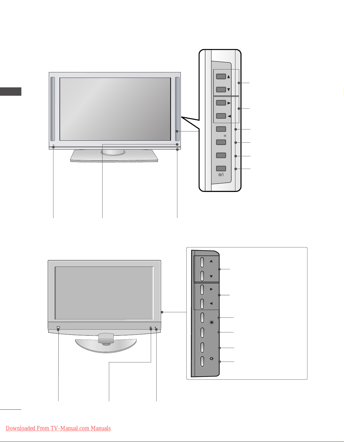
PREPARATION
LCD TV Models: 37LF6*, 42LF6*, 47LF6*, 52LF6
*
Remote Control Sensor
Power/Standby Indicator
• illuminates red in standby mode.
• illuminates green when the set is switched on.
PROGRAMME Buttons
VOLUME Buttons
OK Button
MENU Button
INPUT Button
POWER Button
IInntteelllliiggeenntt EEyyee
Adjusts picture according to
the surrounding conditions.
PR
VOL
OK
MENU
INPUT
/I
Downloaded From TV-Manual.com Manuals
PR
VOL
OK
MENU
INPUT
/I
CH
VOL
6
PREPARATION
PREPARATION
LCD TV Models: 37LY9*, 42LY9*, 47LY9*, 52LY9
*
IInntteelllliiggeenntt EEyyee
Adjusts picture
according to the
surrounding conditions.
Power/Standby Indicator
• illuminates red in standby mode.
• illuminates green when the set is switched on.
PROGRAMME Buttons
VOLUME Buttons
OK Button
MENU Button
INPUT Button
POWER Button
Remote Control Sensor
LCD TV Models: 37/
42LF7
*
CH
VOL
PROGRAM Buttons
VOLUME Buttons
OK Button
MENU Button
INPUT Button
POWER Button
Remote Control
Sensor
IInntteelllliiggeenntt EEyyee
Adjusts picture
according to the surrounding conditions.
Power/Standby Indicator
• illuminates red in standby mode.
• illuminates green when the set is switched on.
PR
VOL
OK
MENU
INPUT
Downloaded From TV-Manual.com Manuals
7
PREPARATION
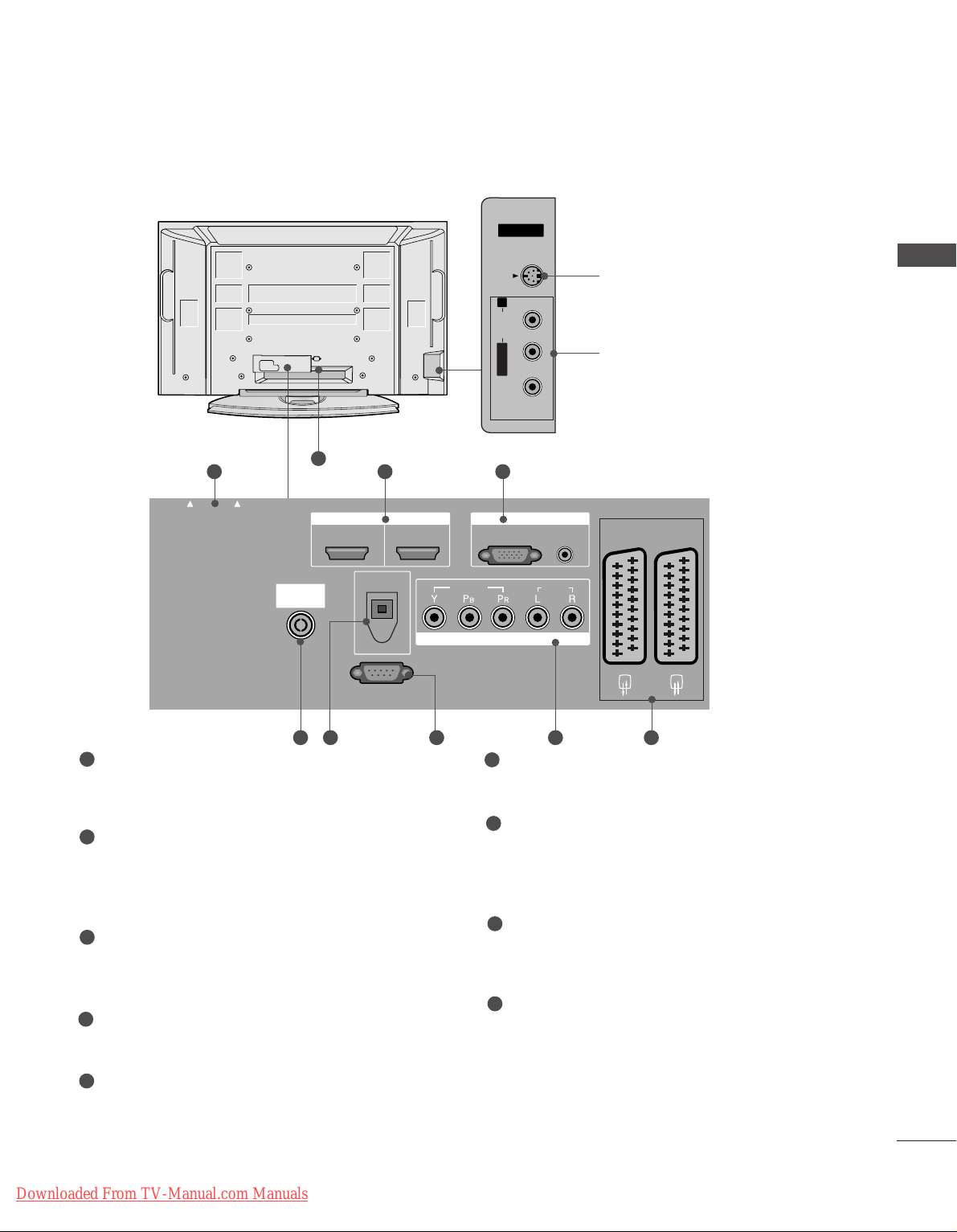
PCMCIA (Personal Computer Memory Card
International Association) Card Slot
(This feature is not available in all countries.)
HDMI Input
Connect a HDMI signal to HDMI IN.
Or DVI(VIDEO)signal to HDMI/DVI port with DVI
to HDMI cable.
RGB/DVI Audio Input
Connect the monitor output from a PC to the
appropriate input port.
Antenna Input
Connect over-the-air signals to this jack.
DIGITAL AUDIO OUT OPTICAL
Connect digital audio from various types of equipment.
Note: In standby mode, these ports do not work.
RS-232C IN (CONTROL & SERVICE) PORT
Connect to the RS-232C port on a PC.
Component Input
Connect a component video/audio device to
these jacks.
Euro Scart Socket (AV1/AV2)
Connect scart socket input or output from an
external device to these jacks.
Power Cord Socket
This TV operates on an AC power. The voltage is
indicated on the Specifications page. Never
attempt to operate the TV on DC power.
1
2
3
4
5
6
7
8
9
BACK PANEL INFORMATION
A
This is a simplified representation of the back panel. Here shown may be somewhat different from your TV.
Plasma TV Models
S-Video Input
Connect S-Video out from an
S-VIDEO device.
Audio/Video Input
Connect audio/video output
from an external device to
these jacks.
AV IN 3V IN 3
L/L/MONOMONO
R
AUDIOAUDIO
VIDEOVIDEO
S-VIDEOS-VIDEO
AV IN 3
L/ MONO
R
AUDIO
VIDEO
S-VIDEO
AUDIO
VIDEO
V 1
V 2
EJECT
PCMCIA
CARD SLOT
RS-232C IN
1 32
84 5 6 7
9
PCMCIA
CARD SLOT
EJECT
ANTENNA
IN
HDMI/DVI IN
12
DIGITAL AUDIO
OUT
OPTICAL
RS-232C IN
(CONTROL & SERVICE)
HDMI IN
RGB IN
RGB
(PC)
VIDEO
COMPONENT IN
(RGB/DVI)
AUDIO
AUDIO
AV 1
AV 2
Downloaded From TV-Manual.com Manuals

8
PREPARATION
PREPARATION
PCMCIA (Personal Computer Memory Card
International Association) Card Slot
(This feature is not available in all countries.)
HDMI Input
Connect a HDMI signal to HDMI IN.
Or DVI(VIDEO)signal to HDMI/DVI port with DVI
to HDMI cable.
RGB/DVI Audio Input
Connect the monitor output from a PC to the
appropriate input port.
Antenna Input
Connect over-the-air signals to this jack.
DIGITAL AUDIO OUT OPTICAL
Connect digital audio from various types of equipment.
Note: In standby mode, these ports do not work.
RS-232C IN (CONTROL & SERVICE) PORT
Connect to the RS-232C port on a PC.
Component Input
Connect a component video/audio device to
these jacks.
Euro Scart Socket (AV1/AV2)
Connect scart socket input or output from an
external device to these jacks.
Power Cord Socket
This TV operates on an AC power. The voltage is
indicated on the Specifications page. Never
attempt to operate the TV on DC power.
1
2
3
4
5
6
7
8
9
LCD TV Models
(Except 37/42LF7*)
AV 3
L/MONO
R
AUDIO
VIDEO
S-VIDEO
AUDIO
VIDEO
ANTENNA
EJECT
HDMI/DVI IN 1
HDMI IN 2
PCMCIA
CARD SLOT
1 2 3
9
S-Video Input
Connect S-Video
out from an SVIDEO device.
Audio/Video
Input
Connect
audio/video output from an external device to
these jacks.
AV IN 3
L/MONO
R
AUDIOAUDIO
VIDEOVIDEO
S-VIDEOS-VIDEO
AV IN 3
L/MONO
R
AUDIOAUDIO
VIDEOVIDEO
S-VIDEOS-VIDEO
84 5 6 7
AV IN 3
L/MONO
R
AUDIO
VIDEO
S-VIDEO
AUDIO
VIDEO
ANTENNA
EJECT
HDMI/DVI IN 1
HDMI IN 2
HDMI IN 3
PCMCIA
CARD SLOT
1 2 5
84 6 7 3
PCMCIA
CARD SLOT
CARD SLOT
EJECT
HDMI/DVI IN 1
ANTENNA
IN
(CONTROL & SERVICE)
PCMCIA
EJECT
HDMI/DVI IN 1
ANTENNA
IN
OPTICAL
RS-232C IN
(CONTROL & SERVICE)
HDMI IN 2
DIGITAL AUDIO OUT
HDMI IN 2
RS-232C IN
RGB
COMPONENT IN
VIDEO
HDMI IN 3
RGB
VIDEO
COMPONENT IN
RGB IN
(PC)
(PC)
RGB IN
AUDIO IN
(RGB/DVI)
AUDIO
OPTICAL
AUDIO IN
(RGB/DVI)
AUDIO
AV 1 AV 2
AV 1 AV 2
DIGITAL AUDIO OUT
Downloaded From TV-Manual.com Manuals
9
LCD TV Models : 37/
42LF7
*
AV IN 2
L/MONO
R
AUDIO
VIDEO
USB IN
AV IN 3
L/ MONO
R
AUDIO
VIDEO
S-VIDEO
AUDIO
VIDEO
V 1
V 2
EJECT
HDMI/DVI IN 1
HDMI IN 2
HDMI IN 3
PCMCIA
CARD SLOT
RS-232C IN
1 2 3
9
S-Video Input
Connect S-Video out from an SVIDEO device.
Audio/Video Input
Connect audio/video output from
an external device to these jacks.
AV IN 3
L/MONO
R
AUDIOAUDIO
VIDEOVIDEO
S-VIDEOS-VIDEO
84 5 6 7
PCMCIA (Personal Computer Memory Card
International Association) Card Slot
(This feature is not available in all countries.)
HDMI Input
Connect a HDMI signal to HDMI IN.
Or DVI(VIDEO)signal to HDMI/DVI port with DVI
to HDMI cable.
DIGITAL AUDIO OUT OPTICAL
Connect digital audio from various types of equipment.
Note: In standby mode, these ports do not work.
Antenna Input
Connect over-the-air signals to this jack.
RS-232C IN (CONTROL & SERVICE) PORT
Connect to the RS-232C port on a PC.
Component Input
Connect a component video/audio device to
these jacks.
RGB/DVI Audio Input
Connect the monitor output from a PC to the
appropriate input port.
Euro Scart Socket (AV1/AV2)
Connect scart socket input or output from an
external device to these jacks.
Power Cord Socket
This TV operates on an AC power. The voltage is
indicated on the Specifications page. Never
attempt to operate the TV on DC power.
1
2
3
4
5
6
7
8
9
PREPARATION
PCMCIA
CARD SLOT
Downloaded From TV-Manual.com Manuals
EJECT
HDMI/DVI IN 1
ANTENNA
IN
HDMI IN 2
RS-232C IN
(CONTROL & SERVICE)
VIDEO
COMPONENT IN
HDMI IN 3
RGB
(PC)
RGB IN
OPTICAL
AUDIO IN
(RGB/DVI)
AUDIO
DIGITAL AUDIO OUT
AV 1
AV 2
10
PREPARATION
PREPARATION
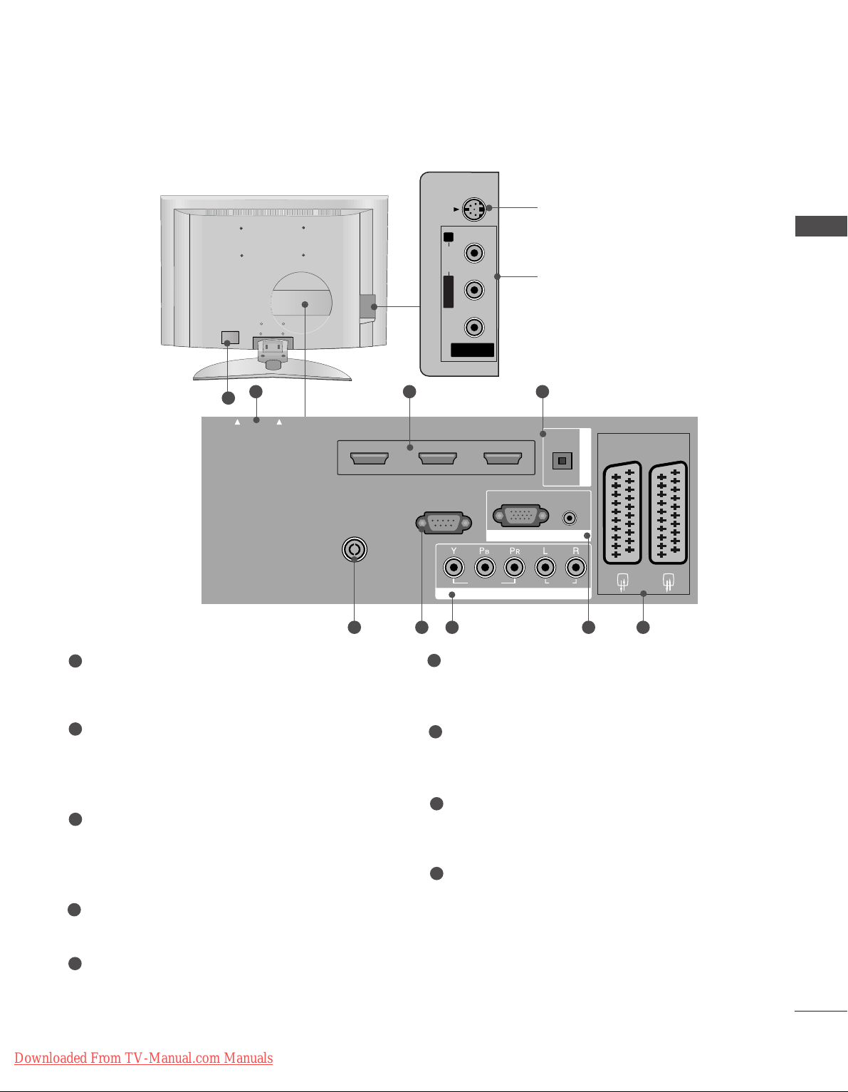
STAND INSTALLATION (Only 37 inch LCD TV Models)
1
2
3
Carefully place the product screen side down on
a cushioned surface that will protect product and
screen from damage.
Assemble the product stand with the product as
shown.
Install the 4 bolts securely, in the back of the
product in the holes provided.
ATTACHING THE TV TO A DESK (Only 37LF7
*
)
WARNING
!
GG
To prevent TV from falling over, the TV should be securely attached to the floor/wall per
installation instructions. Tipping, shaking, or rocking the machine may cause injury.
1-screw
Stand
Desk
The TV must be attached to desk so it cannot be pulled in a forward/backward direction, potentially causing
injury or damaging the product. Use only an attached screw.
Downloaded From TV-Manual.com Manuals
11
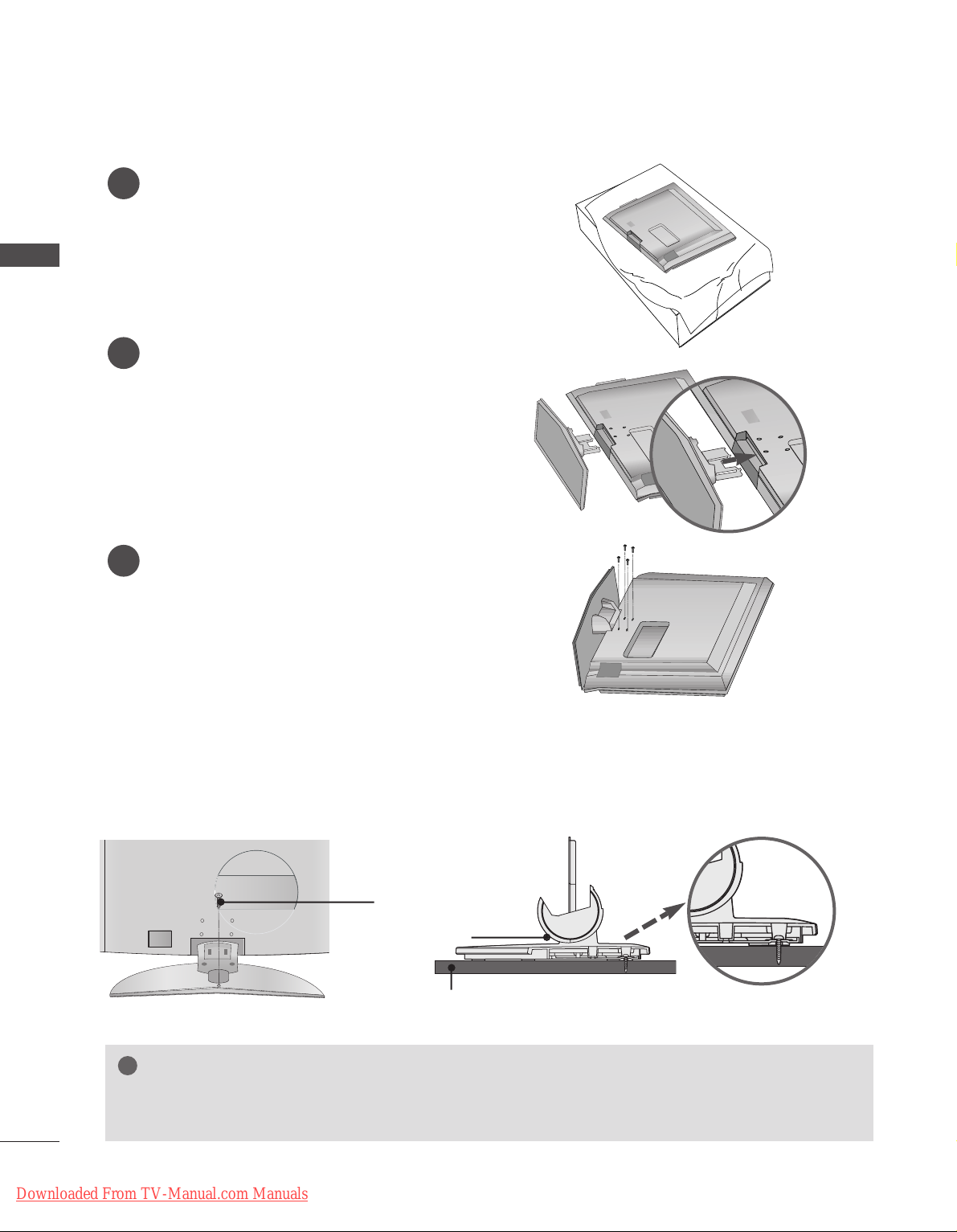
ATTACHING THE TV TO A WALL
■
This feature is not available for all models.
or
2
1
A
Set it up close to the wall so the product doesn’t fall over when it is pushed backwards.
A
The instructions shown below is a safer way to set up the product, which is to fix it on the wall so the
product doesn’t fall over when it is pulled in the forward direction. It will prevent the product from
falling for-ward and hurting people. It will also prevent the product from damage caused by fall. Please
make sure that children don’t climb on or hang from the product.
NOTE
!
G
When moving the product to another place undo the ropes first.
G
Use a product holder or a cabinet that is big and strong enough for the size and weight of the product.
G
To use the product safely make sure that the height of the bracket that is mounted on the wall is same
as that of the product.
2
3
1
1
2
Use the eye-bolts or TV brackets/bolts to fix the product to the wall as shown in the picture.
(If your product has the bolts in the eye-bolts position before inserting the eye-bolts, loosen the bolts.)
* Insert the eye-bolts or TV brackets/bolts and tighten them securely in the upper holes.
Secure the wall brackets with the bolts (not provided as parts of the product, must purchase separately) on
the wall. Match the height of the bracket that is mounted on the wall.
3
Use a sturdy rope (not provided as parts of the product, must purchase separately) to tie the
product. It is safer to tie the rope so it becomes horizontal between the wall and the product.
PREPARATION
Downloaded From TV-Manual.com Manuals
12
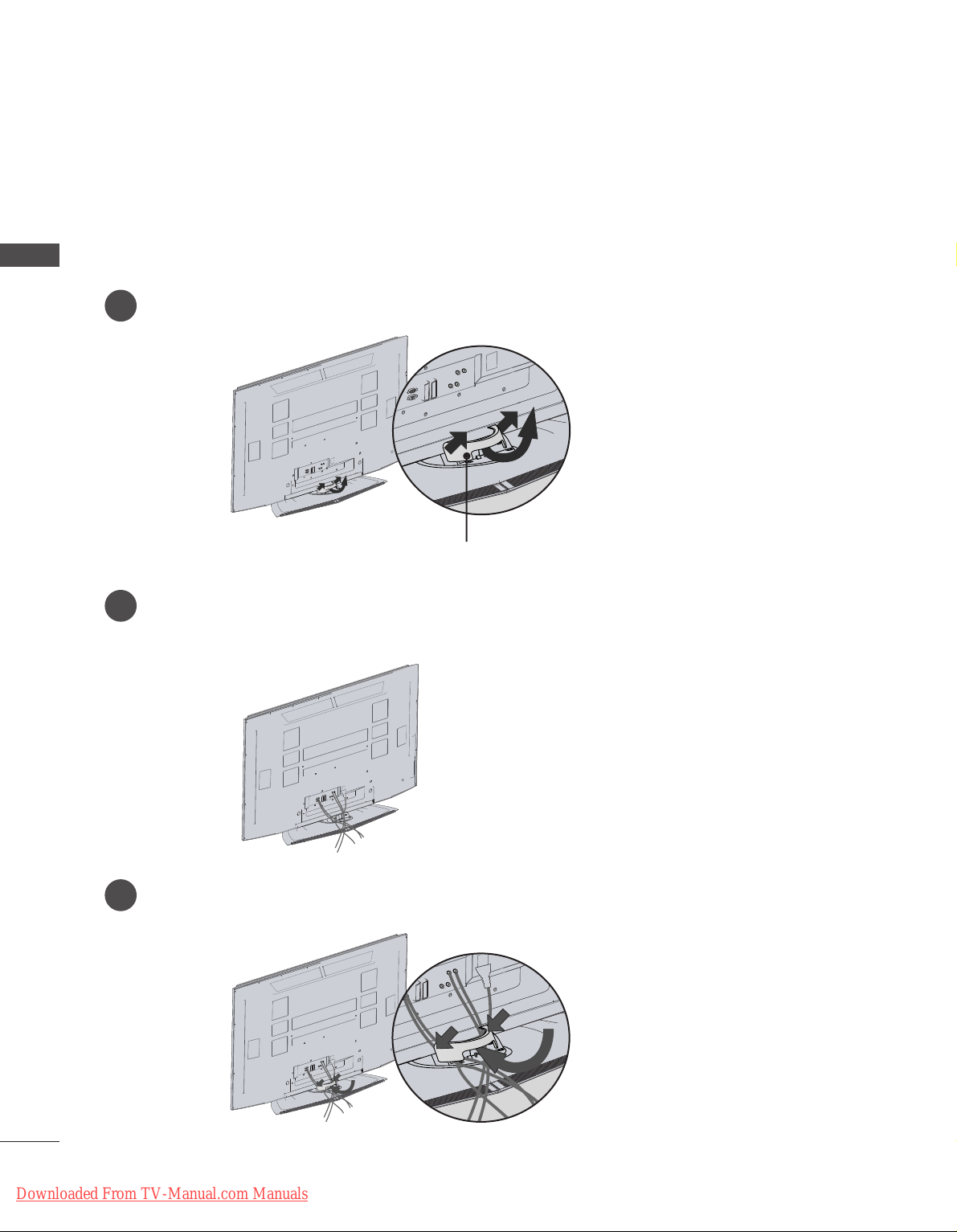
PREPARATION
Plasma TV models
2
1
3
Hold the CABLE MANAGEMENT with both hands and pull it as shown.
Connect the cables as necessary.
To connect an additional equipment, see the External equipment Connections section.
Reinstall the CABLE MANAGEMENT as shown.
CABLE MANAGEMENT
45
°
BACK COVER FOR WIRE ARRANGEMENT
PREPARATION
Downloaded From TV-Manual.com Manuals
13
PREPARATION
LCD TV models
(Except 37/42LF7*)
Connect the cables as necessary.
To connect an additional equipment, see the
EExxtteerrnnaall eeqquuiippmmeenntt CCoonnnneeccttiioonnss
section.
1
Install the
CC AABB LL EE MMAANN AAGGEE MMEENNTT
as shown.
2
Bundle the cables using the supplied twister
holder.
(
This feature is not available for all models.
)
3
Hold the
CC AABBLLEE MM AANN AAGG EEMMEE NNTT
with both
hands and pull it upward.
NOTE
!
GG
Do not hold the CABLE MANAGEMENT when moving the product.
- If the product is dropped, you may be injured or the product may be broken.
How to remove the cable management
CABLE MANAGEMENT
Downloaded From TV-Manual.com Manuals
14
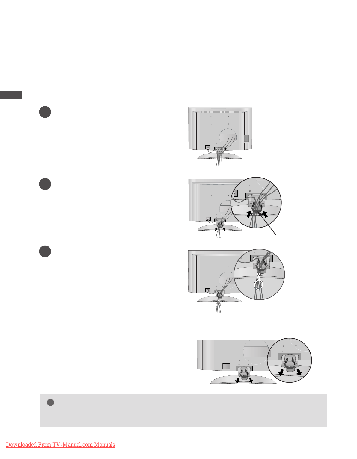
PREPARATION
LCD TV model
(Only 37/42LF7*)
Connect the cables as necessary.
To connect an additional equipment, see the
EExxtteerrnnaall eeqquuiippmmeenntt CCoonnnneeccttiioonnss
section.
Install the
CC AABB LL EE MMAANN AAGGEE MMEENNTT
as shown.
(Insert it as pushing the loops on the both
sides of the cable management.)
Bundle the cables using the supplied twist
holder.
(
This feature is not available for all models.
)
Hold the
CC AABBLLEE MM AANN AAGG EEMMEE NNTT
with both
hands and pull it out.
(Pull it out as holding the loops on the both sides of
the cable management.)
NOTE
!
GG
Do not hold the CABLE MANAGEMENT when moving the product.
- If the product is dropped, you may be injured or the product may be broken.
How to remove the cable management
CABLE MANAGEMENT
1
2
3
PREPARATION
Downloaded From TV-Manual.com Manuals
15
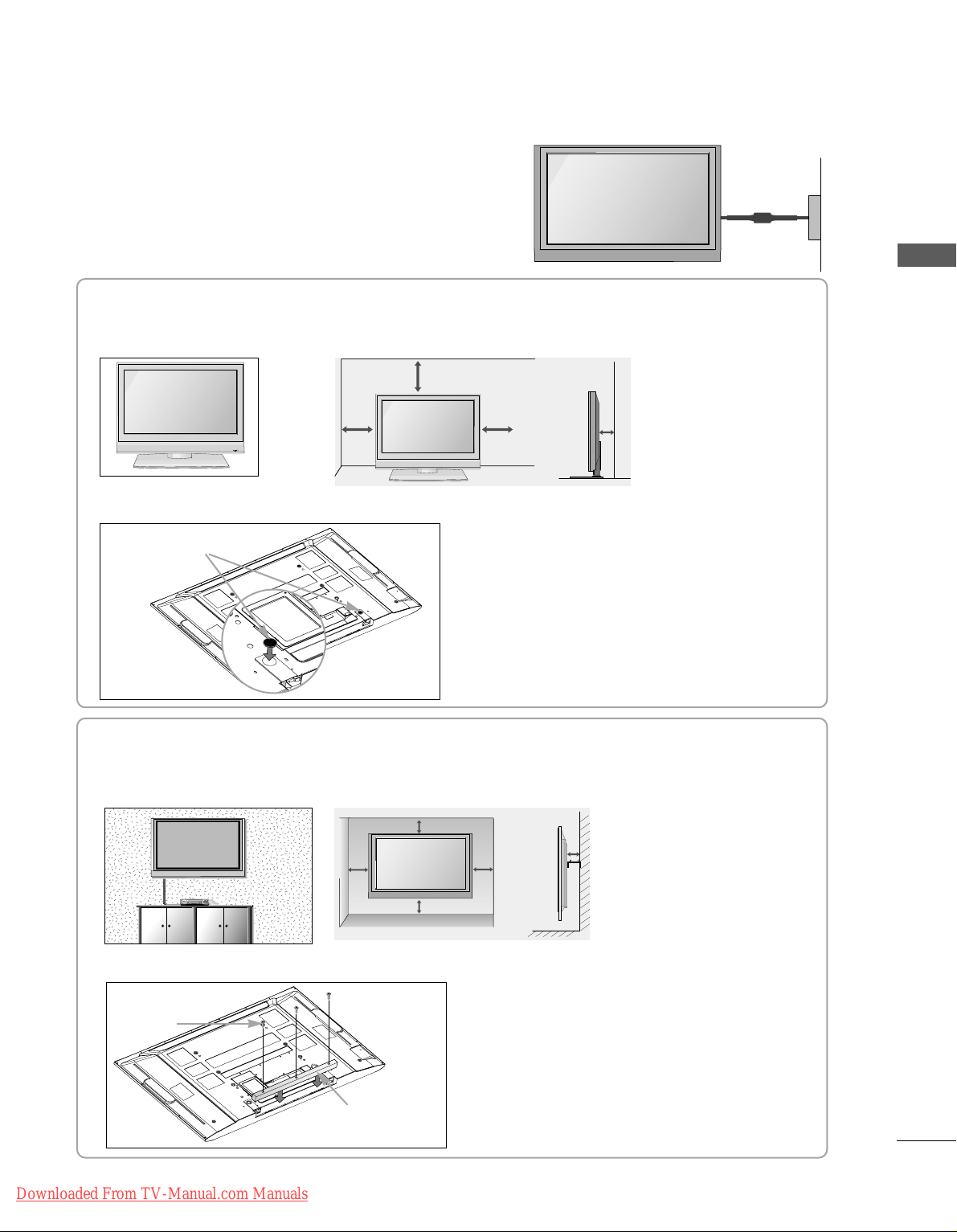
WALL MOUNT: HORIZONTAL INSTALLATION
For adequate ventilation allow a clearance of 4” (10cm) all around the TV. We recommend that you use a wall
mounting bracket of LG brand when mounting the TV to a wall.
4 inches
4 inches
4 inches 4 inches
4 inches
If you want to install the desk-type stand fixture protection cover (Plasma
TTVV mmooddeellss
only)
To prevent the foreign materials from
entering the desk-type stand fixture, fix
the desk-type stand fixture protection
cover by using the supplied bolts as
shown at the figure.
Bolts
Desk-type stand
fixture protection cover
DESKTOP PEDESTAL INSTALLATION
R
For proper ventilation, allow a clearance of 4" on each side and from the wall.
When not using the desk-type stand (60PF9* only )
When not using the desk-type stand,
install the supplied rubber caps for
protecting the desk-type stand fixture
as shown at the figure.
4 inches
4 inches
4 inches
4 inches
Rubber cap
GROUNDING
Ensure that you connect the earth ground wire to prevent
possible electric shock. If grounding methods are not possible, have a qualified electrician install a separate circuit
breaker. Do not try to ground the unit by connecting it to
telephone wires, lightening rods, or gas pipes.
Power Supply
Short-circuit
Breaker
■
The set can be installed in various ways such as on a wall, or on a desktop etc.
■
The set is designed to be mounted horizontally.
PREPARATION
Downloaded From TV-Manual.com Manuals
16
PREPARATION
AV 3
L/ MONO
R
AUDIO
VIDEO
S-VIDEO
AUDIO
VIDEO
AV 1 AV 2
ANTENNA
IN
EJECT
HDMI/DVI IN 1 HDMI IN 2
AV 3
L/ MONO
R
AUDIO
VIDEO
S-VIDEO
AUDIO
VIDEO
AV 1 AV 2
ANTENNA
IN
EJECT
HDMI/DVI IN 1 HDMI IN 2
■
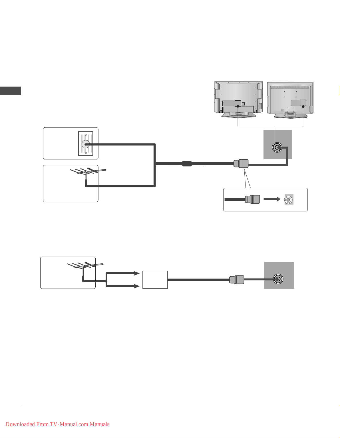
For optimum picture quality, adjust antenna direction.
■
An antenna cable and converter are not supplied.
■
To prevent the equipment damage, never plug in any power cords until you have finished connecting all equipment.
Multi-family Dwellings/Apartments
(Connect to wall antenna socket)
Single-family Dwellings /Houses
(Connect to wall jack for outdoor antenna)
Outdoor
Antenna
(VHF, UHF)
Wall
Antenna
Socket
RF Coaxial Wire (75 ohm)
ANTENNA CONNECTION
Antenna
UHF
Signal
Amplifier
VHF
■
In poor signal areas,to get better picture quality, install a signal amplifier to the antenna as shown to the right.
■
If signal needs to be split for two TVs,use an antenna signal splitter for connection.
- Be careful not to bend the bronze
wire when connecting to an antenna
port.
- 5V antenna power works In Digital
mode only. (Refer to p. 45)
AV IN 3
L/MONO
R
AUDIO
VIDEO
S-VIDEO
AV IN 3
L/MONO
R
AUDIO
VIDEO
S-VIDEO
PREPARATION
Downloaded From TV-Manual.com Manuals
17
EXTERNAL EQUIPMENT SETUP
HD RECEIVER SETUP
■
This TV can receive Digital Over-the-air/Cable signals without an external digital set-top box.However,if you do
receive Digital signals from a digital set-top box or other digital external device,refer to the figure as shown
below.
AUDIO IN
(RGB/DVI)
RGB
(PC)
RGB IN
COMPONENT IN
AUDIOAUDIO
VIDEOVIDEO
AAV 1 AV 2
DIGITAL AUDIO OUT
AUDIO
VIDEO
ANTENNA
IN
HDMI/DVI IN 1 HDMI IN 2
EJECT PCMCIA
CARD SLOT
When connecting with a component cable
Connect the video outputs (Y, PB, P
R
)
of the digital set
top box to the
CC OOMM PPOONNEENN TT IINN VVIIDDEE OO
jacks on the
set.
Connect the audio output of the digital set-top box to
the
CC OOMM PPOONNEENN TT IINN AAUU DDIIOO
jacks on the set.
Turn on the digital set-top box.
(
Refer to the owner’s manual for the digital set-top box.
)
Select
COMPONENT input source with using the
II NNPPUU TT
button on the remote control.
2
3
4
1
Signal
480i/576i
480p/576p
720p/1080i
10 8 0 p
Component
Yes
Yes
Yes
Yes
(60Hz only)
HDMI1/2
No
Yes
Yes
Yes
(24Hz/50Hz/60Hz)
HDMI3
(Only 37/42LF7*, 42LY99)
No
Yes
Yes
Yes
(24Hz/50Hz/60Hz)
1 2
■
To prevent the equipment damage, never plug in any power cords until you have finished connecting all equipment.
■
This part of EXTERNAL EQUIPMENT SETUP mainly use pictures for the LCD TV models.
EXTERNAL EQUIPMENT SETUP
Downloaded From TV-Manual.com Manuals
18
AUD
(RG
RGB
(PC)
RGB IN
COMPONENT I
AUDIAUDIO
VIDEO
AV 1 AV 2
ANTENNAANTENNA
IN IN
HDMI/DVI IN 1HDMI/DVI IN 1 HDMI IN 2HDMI IN 2
EJECT EJECT PCMCIA
RS-232C INRS-232C IN
(CONTROL & SERVICE)
OPTICAL
DIGITAL AUDIO OUT
AUDIO
VIDEO
AV 1 AV 2
ANTENNA
IN
HDMI/DVI IN 1 HDMI IN 2
EJECT PCMCIA
CARD SLOT
RS-232C IN
AUDIO
VIDEO
AV 1 AV 2
ANTENNA
IN
HDMI/DVI IN 1 HDMI IN 2
EJECT PCMCIA
CARD SLOT
RS-232C IN
When connecting with a HDMI cable
Connect the digital set-top box to
HHDDMM II//DDVVII IINN 11
or
HHDDMM II II NN 22
jack on the set.
Turn on the digital set-top box.
(
Refer to the owner’s manual for the digital set-top box.
)
Select
HDMI1 or HDMI2 input source with using the
II NNPPUUTT
button on the remote control.
2
3
1
1
Except
37/42LF7*, 42LY99
RGB IN
COMPONENT IN
ANTENNAANTENNA IN
HDMI/DVI IN 1 HDMI IN 2 HDMI IN 3
RS-232C INRS-232C IN
(CONTROL(CONTROL & SER & SERVICE)VICE)
AUD
(RGB
RGB
(PC)
AUDIAUDIO
VIDEO
AV 1 AV 2
EJECT EJECT PCMCIA
OPTIC
ANTENNA IN
HDMI/DVI IN 1 HDMI IN 2 HDMI IN 3
RS-232C IN
(CONTROL & SERVICE)
VIDEO
EJECT PCMCIA
CARD SLOT
Connect the digital set-top box to
HHDDMM II//DDVVII IINN 11
,
HHDDMM II II NN 22
or
HHDDMM II II NN 33
jack on the set.
Turn on the digital set-top box.
(
Refer to the owner’s manual for the digital set-top box.
)
Select
HDMI1, HDMI2 or HDMI3 input source with
using the
II NNPPUUTT
button on the remote control.
2
3
1
1
Only
37/42LF7*, 42LY99
EXTERNAL EQUIPMENT SETUP
Downloaded From TV-Manual.com Manuals
19
AUDIO IN
(RGB/DVI)
RGB
(PC)
RGB IN
COMPONENT IN
AUDIO
VIDEO
AAV 1 AV 2
HDMI/DVI IN 1HDMI/DVI IN 1 HDMI IN 2HDMI IN 2
RS-232C INRS-232C IN
(CONTROL & SERVICE)
OPTICAL
DIGITAL AUDIO OUT
1
2
Connect the digital set-top box to
HHDDMM II//DDVVII IINN 11
jack on the set.
Connect the audio output of the digital set-top box to
the
AAUUDDIIOO IINN ((RRGGBB// DDVV II))
jack on the set.
Turn on the digital set-top box. (Refer to the owner’s
manual for the digital set-top box.
)
Select
HDMI1 input source with using the
II NNPPUUTT
button on the remote control.
2
3
4
1
When connecting with a HDMI to DVI cable
Except
37/42LF7*, 42LY99
RGB IN
COMPONENT IN
ANTENNAANTENNA IN
HDMI/DVI IN 1 HDMI IN 2 HDMI IN 3
RS-232C INRS-232C IN
(CONTROL(CONTROL & SER & SERVICE)VICE)
AUDIO IN
(RGB/DVI)
RGB
(PC)
AUDIO
VIDEO
AVV 1 AV 2
OPTICAL
DIGITAL AUDIO OUT
1
2
Connect the digital set-top box to
HHDDMM II//DDVVII IINN 11
jack on the set.
Connect the audio output of the digital set-top box to
the
AAUUDDIIOO IINN ((RRGGBB// DDVV II))
jack on the set.
Turn on the digital set-top box. (Refer to the owner’s
manual for the digital set-top box.
)
Select
HDMI1 input source with using the
II NNPPUUTT
button on the remote control.
2
3
4
1
Only
37/42LF7*, 42LY99
EXTERNAL EQUIPMENT SETUP
Downloaded From TV-Manual.com Manuals

20
EXTERNAL EQUIPMENT SETUP
DVD SETUP
When connecting with a component cable
AUDIO IN
(RGB/DVI)
RGB
(PC)
RGB IN
COMPONENT IN
AUDIOAUDIO
VIDEOVIDEO
AAV 1 AV 2
DIGITAL AUDIO OUT
L/ MONO
R
AUDIO
VIDEO
S-VIDEO
Component Input ports
To get better picture quality, connect a DVD player to the component input ports as shown below.
Component ports on the TV
YPB PR
Video output ports
on DVD player
Y
Y
Y
Y
PB
B-Y
Cb
Pb
P
R
R-Y
Cr
Pr
Connect the video outputs (Y, P
B, PR
)
of the DVD to the
CC OOMM PPOONNEENN TT IINN VVIIDD EEOO
jacks on the set.
Connect the audio outputs of the DVD to the
CC OOMM PPOONNEENN TT IINN AAUU DDIIOO
jacks on the set.
Turn on the DVD player, insert a DVD.
Select
COMPONENT input source with using the
II NNPPUUTT
button on the remote control.
Refer to the DVD player's manual for operating
instructions.
2
3
4
5
1
1 2
EXTERNAL EQUIPMENT SETUP
Downloaded From TV-Manual.com Manuals

21
EXTERNAL EQUIPMENT SETUP
When connecting with a Euro Scart
Connect the Euro scart socket of the DVD to the
AAVV11
Euro scart socket on the set.
Turn on the DVD player, insert a DVD.
Select
AV 1 input source with using the
II NNPPUUTT
button
on the remote control.
If connected to
AV 2 Euro scart socket, select AV2
input source.
Refer to the DVD player's manual for operating
instructions.
2
3
4
1
AUDIO
VIDEO
AV 1 AV 2
ANTENNA
IN
HDMI/DVI IN 1 HDMI IN 2
EJECT PCMCIA
CARD SLOT
RS-232C IN
AV IN 3
L/ MONO
R
AUDIO
VIDEO
S-VIDEO
AUDIO IN
(RGB/DVI)
AUDIOAUDIO
AV 1V 1 AV 2V 2
(R) AUDIO (L)
AUDIO/
VIDEO
1
NOTE
!
GG
If you want to use the EURO scart cable, you have to use
the signal shielded Euro scart cable.
When connecting with an S-Video cable
L R
S-VIDEOVIDEO
OUTPUT
SWITCH
ANT IN
ANT OUT
AV IN 3V IN 3
L/L/MONOMONO
R
AUDIOAUDIO
VIDEOVIDEO
S-VIDEOS-VIDEO
Connect the S-VIDEO output of the DVD to the
SS--
VVIIDDEEOO
input on the set.
Connect the audio outputs of the DVD to the
AAUUDDIIOO
input jacks on the set.
Turn on the DVD player, insert a DVD.
Select
AV 3 input source with using the
II NNPPUUTT
button
on the remote control.
Refer to the DVD player's manual for operating instructions.
2
3
4
5
1
1
2
Downloaded From TV-Manual.com Manuals
22
EXTERNAL EQUIPMENT SETUP
AUD
(RGB
RGB
(PC)
RGB IN
COMPONENT IN
AUDIO
VIDEO
AV 1 AV 2
ANTENNAANTENNA
IN IN
HDMI/DVI IN 1HDMI/DVI IN 1 HDMI IN 2HDMI IN 2
EJECT PCMCIA
RS-232C INRS-232C IN
(CONTROL & SERVICE)
OPTICAL
DIGITAL AUDIO OUT
AV IN 3
L/ MONO
R
AUDIO
VIDEO
S-VIDEO
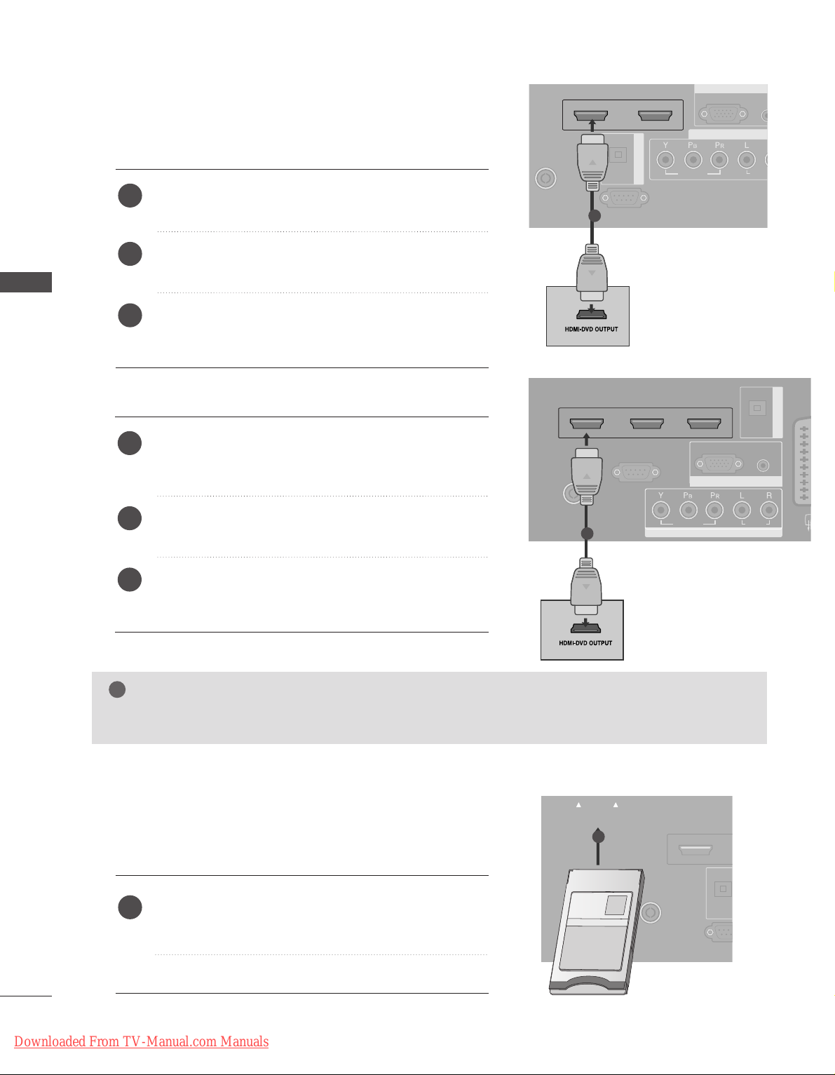
When connecting HDMI cable
Connect the HDMI output of the DVD to the
HHDDMMII//DDVVII
IINN 11
or
HHDDMMII IINN 22
jack on the set.
Select
HDMI1or HDMI2 input source with using the
II NNPPUUTT
button on the remote control.
Refer to the DVD player's manual for operating
instructions.
1
2
3
Insert the CI Module to
PPCC MMCC II AA
(Personal Computer
Memory Card International Association)
CC AARRDD SS LL OOTT
of TV as shown.
For further information, see p.48.
1
GG
TV can receive the video and audio signal simultaneously with using a HDMI cable.
GG
If the DVD does not support Auto HDMI, you need to set the output resolution appropriately.
NOTE
!
1
INSERTION OF CI MODULE
(This feature is not available in all countries.)
AUDIO
VIDEO
AV 1 AV 2
ANTENNAANTENNA
IN IN
HDMI IN 1HDMI IN 1 HDMI IN 2
EJECT EJECT PCMCIAPCMCIA
CARD SLOT CARD SLOT
RS-232RS-232C IN
(CONTROL &
OPTICA
TVTVTV
-- TToo vvii eeww tthh ee ssccrraammbbll eedd ((ppaayy)) sseerrvvii cceess iinn ddii ggiittaall TTVV
mmooddee..
1
Except
37/42LF7*, 42LY99
Only
37/42LF7*, 42LY99
RGB IN
COMPONENT IN
ANTENNAANTENNA IN
HDMI/DVI IN 1 HDMI IN 2 HDMI IN 3
RS-232C INRS-232C IN
(CONTROL(CONTROL & SER & SERVICE)VICE)
AUDIO IN
(RGB/DVI)
RGB
(PC)
AUDIO
VIDEO
AVV 1 AV 2
OPTICAL
DIGITAL AUDIO OUT
Connect the HDMI output of the DVD to the
HHDDMM II//DDVVII II NN 11,HHDDMM II II NN 22
or
HHDDMM II II NN 33
jack
on the set.
Select
HDMI1, HDMI2 or HDMI3 input source with
using the
II NNPPUUTT
button on the remote control.
Refer to the DVD player's manual for operating
instructions.
1
2
3
1
EXTERNAL EQUIPMENT SETUP
Downloaded From TV-Manual.com Manuals
23
EXTERNAL EQUIPMENT SETUP
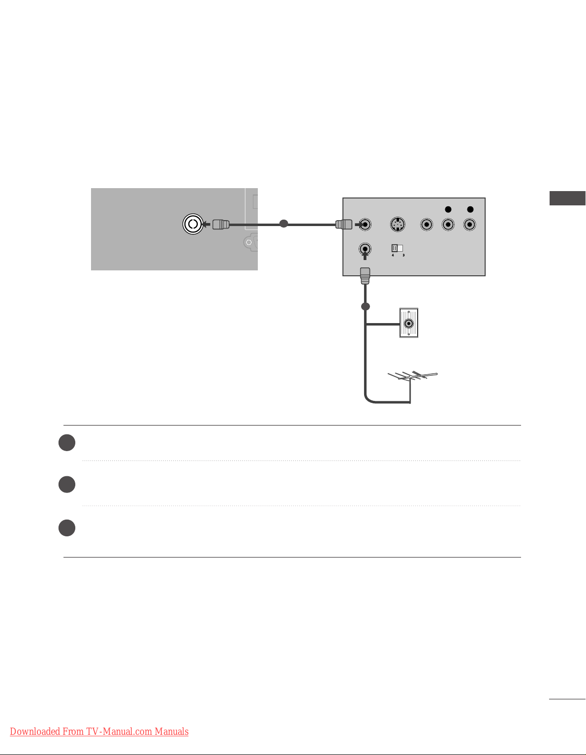
When connecting with an antenna
■
To avoid picture noise (interference), leave an adequate distance between the VCR and TV.
■
Typically a frozen still picture from a VCR. If the 4:3 picture format is used; the fixed images on the sides of
the screen may remain visible on the screen.
AUDIOAUDIO
VIDEOVIDEO
AV 1 AV 2
ANTENNA
IN
HDMI/DVI IN 1 HDMI IN 2
EJECT PCMCIA
CARD SLOT
RS-232C INRS-232C IN
(CONTROL & SERVICE)
OPTICAL
DIGITAL AUDIO OU
OUTPUT
SWITCH
ANT IN
R
S-VIDEO VIDEO
ANT OUT
L
Wall Jack
Antenna
Connect the
AANN TT OOUUTT
socket of the VCR to the
AANN TTEENN NNAA IINN
socket on the set.
Connect the antenna cable to the
AANN TT II NN
socket of the VCR.
Press the
PPLLAA YY
button on the VCR and match the appropriate programme between the TV and VCR for
viewing.
VCR SETUP
1
2
2
3
1
Downloaded From TV-Manual.com Manuals
24
EXTERNAL EQUIPMENT SETUP
When connecting with a Euro Scart
Connect the Euro scart socket of the VCR to the
AAVV11
Euro scart socket on the set.
Insert a video tape into the VCR and press PLAY on
the VCR. (Refer to the VCR owner’s manual.)
Select
AV 1 input source with using the
II NNPPUUTT
button
on the remote control.
If connected to
AAVV22
Euro scart socket, select
AV 2
input source.
2
3
4
1
AUDIO
VIDEO
AV 1 AV 2
ANTENNA
IN
HDMI/DVI IN 1 HDMI IN 2
EJECT PCMCIA
CARD SLOT
RS-232C IN
AUDIO IN
(RGB/DVI)
(PC)
RGB IN
AUDIOAUDIO
AV 1V 1 AV 2V 2
(R) AUDIO (L)
AUDIO/
VIDEO
L/ MONO
R
AUDIO
VIDEO
S-VIDEO
L/ MONO
R
AUDIO
VIDEO
S-VIDEO
1
NOTE
!
GG
If you want to use the EURO scart cable, you have to use the signal shielded Euro scart cable.
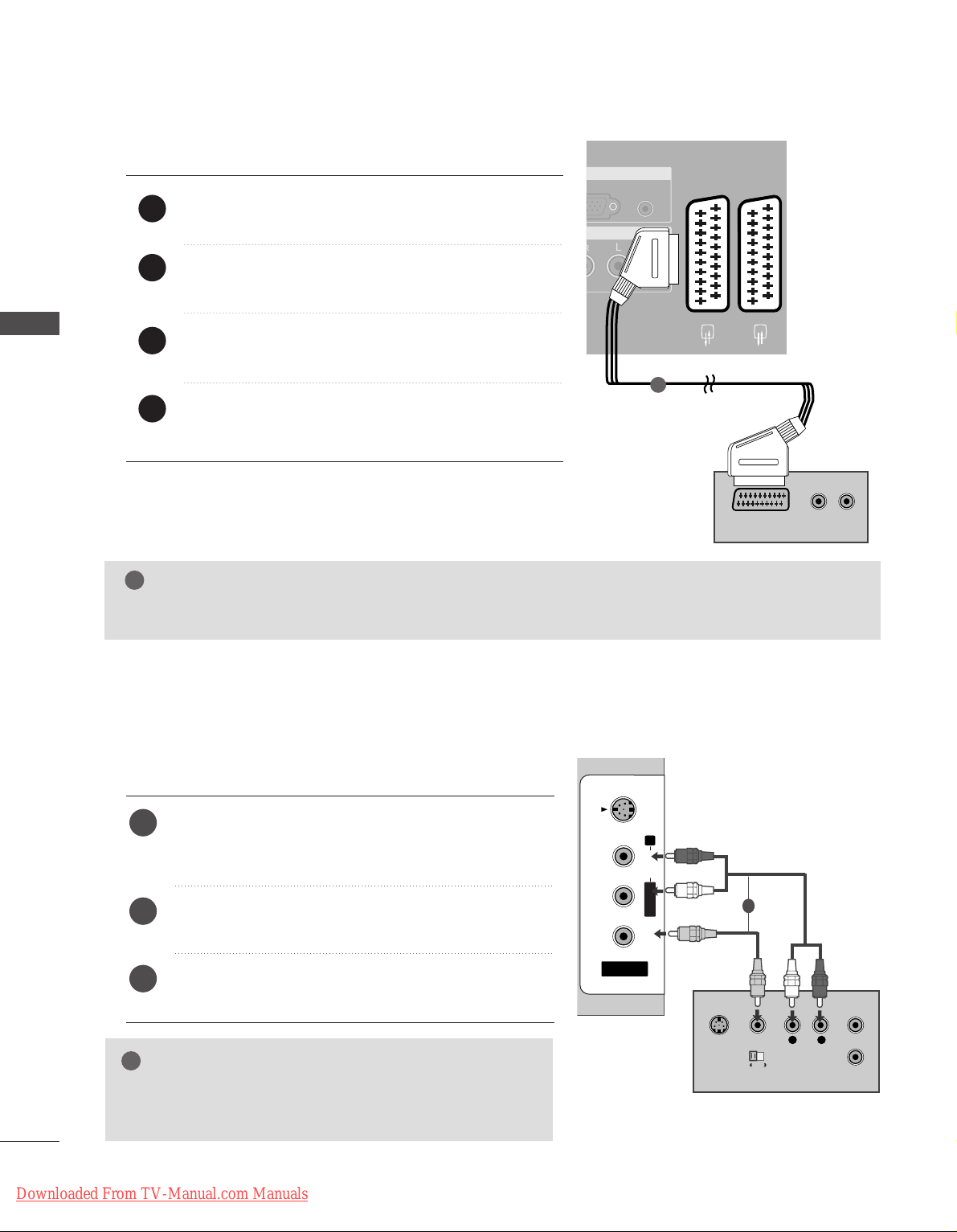
When connecting with a RCA cable
L
R
S-VIDEO
VIDEO
OUTPUT
SWITCH
ANT IN
ANT OUT
AV IN 3
L/ MONO
R
AUDIO
VIDEO
S-VIDEO
AV IN 3V IN 3
L/L/MONOMONO
R
AUDIOAUDIO
VIDEOVIDEO
S-VIDEOS-VIDEO
Connect the
AAUUDD II OO/VVII DDEEOO
jacks between TV and
VCR. Match the jack colors (Video = yellow, Audio Left
= white, and Audio Right = red)
Insert a video tape into the VCR and press PLAY on
the VCR. (Refer to the VCR owner’s manual.
)
Select
AV 3 input source using the
II NNPPUUTT
button on
the remote control.
1
2
3
GG
If you have a mono VCR, connect the audio cable from the
VCR to the
AAUUDDIIOO LL//MMOONNOO
jack of the set.
NOTE
!
1
EXTERNAL EQUIPMENT SETUP
Downloaded From TV-Manual.com Manuals
25
EXTERNAL EQUIPMENT SETUP
GG
If both S-VIDEO and VIDEO sockets have been connected to
the S-VHS VCR simultaneously, only the S-VIDEO can be
received.
NOTE
!
L
R
S-VIDEO
VIDEO
OUTPUT
SWITCH
ANT IN
ANT OUT
AV IN 3V IN 3
L/L/MONOMONO
R
AUDIOAUDIO
VIDEOVIDEO
S-VIDEOS-VIDEO
When connecting with an S-Video cable
Connect the S-VIDEO output of the VCR to the
SS--
VV II DD EEOO
input on the set. The picture quality is
improved; compared to normal composite (RCA cable)
input.
Connect the audio outputs of the VCR to the
AAUUDDIIOO
input jacks on the set.
Insert a video tape into the VCR and press PLAY on the
VCR. (Refer to the VCR owner’s manual.)
Select
AV 3 input source with using the
IINNPPUUTT
button on
the remote control.
2
3
4
1
1 2
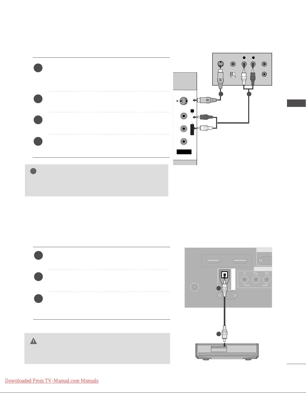
DIGITAL AUDIO OUT SETUP
Send the TV’s audio to external audio equipment via the Digital Audio Output (Optical)port.
G
Do not look into the optical output port. Looking at the
laser beam may damage your vision.
CAUTION
RGB
(PC
R
COMP
AUDIO
VIDEOVIDEO
AV 1 AV 2
ANTENNA
IN
HDMI/DVI IN 1HDMI/DVI IN 1 HDMI IN 2HDMI IN 2
EJECT PCMCIA
RS-232C IN
(CONTROL & SERVICE)
OPTICAL
DIGITAL AUDIO OUT
Connect one end of an optical cable to the TV Digital
Audio (Optical)Output port.
Connect the other end of the optical cable to the digital audio (optical)input on the audio equipment.
Set the “TV Speaker option - Off ” in the AUDIO menu.
(
G
pp..7788
). See the external audio equipment instruction
manual for operation.
2
3
1
1
2
Downloaded From TV-Manual.com Manuals

26
EXTERNAL EQUIPMENT SETUP
OTHER A/V SOURCE SETUP
Connect the
AAUUDDIIOO/VVIIDDEEOO
jacks between TV and external equipment. Match the jack colors
.
(
Video = yellow, Audio Left = white, and Audio Right = red
)
Select AV 3 input source with using the
II NNPPUUTT
button on the remote control.
Operate the corresponding external equipment.
Refer to external equipment operating guide.
L R
VIDEO
AV IN 3V IN 3
L/L/MONOMONO
R
AUDIOAUDIO
VIDEOVIDEO
S-VIDEOS-VIDEO
Camcorder
Video Game Set
1
1
2
3
EXTERNAL EQUIPMENT SETUP
Downloaded From TV-Manual.com Manuals
27
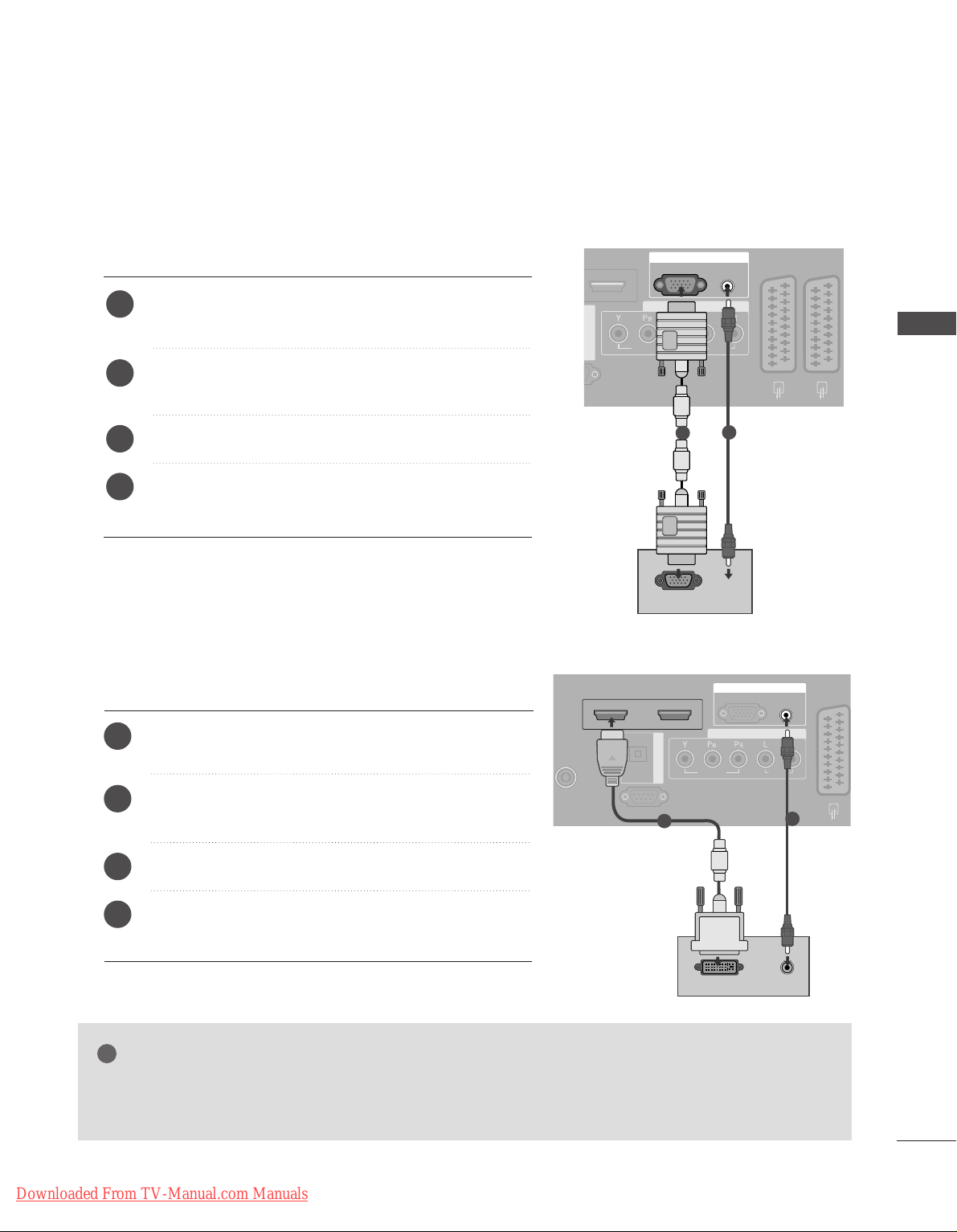
PC SETUP
This TV provides Plug and Play capability, meaning that the PC adjusts automatically to the TV's settings.
When connecting with a D-sub 15 pin cable
AUDIO IN
(RGB/DVI)
RGB
(PC)
RGB IN
COMPONENT IN
AUDIOAUDIO
VIDEOVIDEO
AV 1V 1 AV 2V 2
INRS-232C IN
DIGITAL AUDIO OUT
RGB OUTPUT
AUDIO
Connect the RGB output of the PC to the
RR GGBB ((PPCC
))
jack on the set.
Connect the PC audio output to the
AAUUDDIIOO IINN
((RRGGBB//DDVVII ))
jack on the set.
Turn on the PC and the set.
Select
RGB input source with using the
II NNPPUU TT
button
on the remote control.
2
3
4
1
1
2
When connecting with a HDMI to DVI cable
GG
If the PC has a DVI output and no HDMI output, a separated audio connection is necessary.
GG
If the PC does not support Auto DVI, you need to set the output resolution appropriately.
NOTE
!
AUDIO
VIDEO
AV 1 AV 2
ANTENNA
IN
HDMI/DVI IN 1 HDMI IN 2
EJECT PCMCIA
RS-232C IN
AUDIO IN
(RGB/DVI)
RGB
(PC)
RGB IN
COMPONENT IN
AUDIOAUDIO
VIDEOVIDEO
AV 1V 1 AV 2
IN IN
HDMI/DVI IN 1 HDMI IN 2
RS-232C INRS-232C IN
(CONTROL & SERVICE)
OPTICAL
DIGITAL AUDIO OUT
DVI-PC OUTPUT
AUDIO
1
2
Connect the DVI output of the PC to the
HHDDMM II //DDVVII
II NN 11
jack on the set.
Connect the PC audio output to the
AAUUDDIIOO IINN
((RRGGBB//DDVVII ))
jack on the set.
Turn on the PC and the set
Select
HDMI1 input source with using the
II NNPPUUTT
button on the remote control.
2
3
4
1
EXTERNAL EQUIPMENT SETUP
Downloaded From TV-Manual.com Manuals

28
EXTERNAL EQUIPMENT SETUP
NOTE
!
G
To enjoy vivid picture and sound, connect a PC to
the set.
G
Avoid keeping a fixed image on the set’s screen for
a long period of time. The fixed image may become
permanently imprinted on the screen; use a screen
saver when possible.
G
Connect PC to the RGB (PC) or HDMI IN (or
HDMI/DVI IN) port of the set; change the resolution output of PC accordingly.
G
There might be noise according to some resolution,
vertical pattern, contrast or brightness in PC mode.
Change the PC mode into another resolution or
change the refresh rate into another rate or adjust
the brightness and contrast on the menu until the
picture is clean. If the refresh rate of the PC graphic card can not be changed, change the PC graphic card or consult it to the manufacturer of the PC
graphic card.
G
The synchronization input waveform for Horizontal
and Vertical frequencies are separate.
G
We recommend using 1920x1080 (Reduced
Blanking Timing), 60Hz for the PC mode, they provide the best picture quality.
G
In Plasma TV models, we recommend using
1024x768, 60Hz for the PC mode, they provide
the best picture quality.
G
Connect the signal cable from the monitor output
port of the PC to the RGB (PC) port of the set or
the signal cable from the HDMI output port of the
PC to the HDMI IN (or HDMI/DVI IN) port on the
set.
G
Connect the audio cable from the PC to the Audio
input on the set. (Audio cables are not included
with the set).
G
If using a sound card, adjust PC sound as required.
G
This set uses a VESA Plug and Play Solution. The
set provides EDID data to the PC system with a
DDC protocol. The PC adjusts automatically when
using this set.
G
DDC protocol is preset for RGB (Analog RGB),
HDMI (Digital RGB) mode.
G
If required, adjust the settings for Plug and Play
functionally.
G
If graphic card on the PC does not output analog
and digital RGB simultaneously, connect only one
of either RGB or HDMI IN (or HDMI/DVI IN) to
display the PC on the set.
G
If graphic card on the PC does output analog and
digital RGB simultaneously, set the set to either
RGB or HDMI; (the other mode is set to Plug and
Play automatically by the set.)
G
DOS mode may not work depending on video card
if you use a HDMI to DVI cable.
G
When you use too long RGB-PC cable, there might
be a noise on the screen. We recommend using
under 5m of the cable. It provides the best picture
quality.
EXTERNAL EQUIPMENT SETUP
Downloaded From TV-Manual.com Manuals
Loading...