

LG 42pj550 schematic
PLASMA TV
SERVICE MANUAL
CAUTION
BEFORE SERVICING THE CHASSIS,
READ THE SAFETY PRECAUTIONS IN THIS MANUAL.
CHASSIS : PD01A
MODEL : 42PJ550 42PJ550-ZD
North/Latin America http://aic.lgservice.com
Europe/Africa http://eic.lgservice.com
Asia/Oceania http://biz.lgservice.com
Internal Use Only
Printed in Korea
P/NO : MFL62881205(1002-REV00)

- 2 -
LGE Internal Use OnlyCopyright ©2010 LG Electronics Inc. All rights reserved.
Only for training and service purposes
CONTENTS
CONTENTS ............................................................................................................................... 2
SAFETY PRECAUTIONS ...........................................................................................................3
SPECIFICATION.........................................................................................................................4
ADJUSTMENT INSTRUCTION ..................................................................................................7
TROUBLESHOOTING GUIDE .................................................................................................12
BLOCK DIAGRAM ...................................................................................................................23
EXPLODED VIEW ...................................................................................................................24
SVC. SHEET ................................................................................................................................
- 3 -
LGE Internal Use OnlyCopyright ©2010 LG Electronics Inc. All rights reserved.
Only for training and service purposes
SAFETY PRECAUTIONS
Many electrical and mechanical parts in this chassis have special safety-related characteristics. These parts are identified by in the
Schematic Diagram and Exploded View.
It is essential that these special safety parts should be replaced with the same components as recommended in this manual to prevent
X-RADIATION, Shock, Fire, or other Hazards.
Do not modify the original design without permission of manufacturer.
General Guidance
An isolation Transformer should always be used during the
servicing of a receiver whose chassis is not isolated from the AC
power line. Use a transformer of adequate power rating as this
protects the technician from accidents resulting in personal injury
from electrical shocks.
It will also protect the receiver and it's components from being
damaged by accidental shorts of the circuitry that may be
inadvertently introduced during the service operation.
If any fuse (or Fusible Resistor) in this monitor is blown, replace it
with the specified.
When replacing a high wattage resistor (Oxide Metal Film Resistor,
over 1W), keep the resistor 10mm away from PCB.
Keep wires away from high voltage or high temperature parts.
Due to high vacuum and large surface area of picture tube,
extreme care should be used in handling the Picture Tube.
Do not lift the Picture tube by it's Neck.
Leakage Current Cold Check(Antenna Cold Check)
With the instrument AC plug removed from AC source, connect an
electrical jumper across the two AC plug prongs. Place the AC
switch in the on position, connect one lead of ohm-meter to the AC
plug prongs tied together and touch other ohm-meter lead in turn to
each exposed metallic parts such as antenna terminals, phone
jacks, etc.
If the exposed metallic part has a return path to the chassis, the
measured resistance should be between 1MΩ and 5.2MΩ.
When the exposed metal has no return path to the chassis the
reading must be infinite.
An other abnormality exists that must be corrected before the
receiver is returned to the customer.
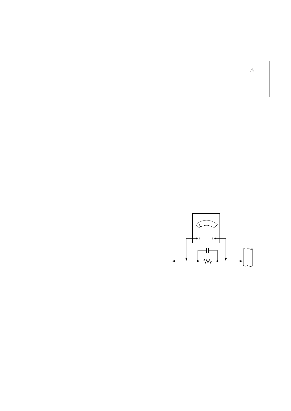
Leakage Current Hot Check (See below Figure)
Plug the AC cord directly into the AC outlet.
Do not use a line Isolation Transformer during this check.
Connect 1.5K/10watt resistor in parallel with a 0.15uF capacitor
between a known good earth ground (Water Pipe, Conduit, etc.)
and the exposed metallic parts.
Measure the AC voltage across the resistor using AC voltmeter
with 1000 ohms/volt or more sensitivity.
Reverse plug the AC cord into the AC outlet and repeat AC voltage
measurements for each exposed metallic part. Any voltage
measured must not exceed 0.75 volt RMS which is corresponds to
0.5mA.
In case any measurement is out of the limits specified, there is
possibility of shock hazard and the set must be checked and
repaired before it is returned to the customer.
Leakage Current Hot Check circuit
1.5 Kohm/10W
To Instrument's
exposed
METALLIC PARTS
Good Earth Ground
such as WATER PIPE,
CONDUIT etc.
AC Volt-meter
IMPORTANT SAFETY NOTICE
0.15uF
- 4 -
LGE Internal Use OnlyCopyright ©2010 LG Electronics Inc. All rights reserved.
Only for training and service purposes
SPECIFICATION
NOTE : Specifications and others are subject to change without notice for improvement
.
V Application Range
This spec is applied to the PLASMA TV used PD01A Chassis.
V Specification
Each part is tested as below without special appointment.
(1) Temperature : 25 °C ± 5 °C (77 °F ± 9 °F), CST : 40 ± 5
(2) Relative Humidity: 65 % ± 10 %
(3) Power Voltage: Standard Input voltage (100 V - 240 V ~, 50 / 60 Hz)
* Standard Voltage of each product is marked by models.
(4) Specification and performance of each parts are followed each drawing and specification by part number in accordance with
BOM.
(5) The receiver must be operated for about 20 minutes prior to the adjustment.
V Test Method
(1) Performance : LGE TV test method followed.
(2) Demanded other specification
Safety : CE, IEC specification
EMC : CE, IEC
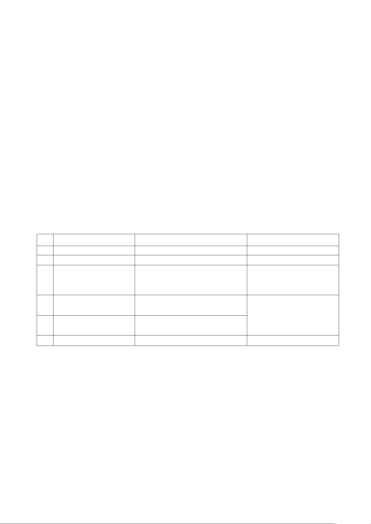
V Module Specification
(1) 42” HD
Display Screen Device
Aspect Ratio
PDP Module
Operating Environment
Storage Environment
Input Voltage
1
2
3
4
5
6
No Item Specification Remark
106 cm (42 inch) Wide Color Display Module
16:9
PDP42 T1####,
RGB Closed(Well) Type, Glass Filter(38 %)
Pixel Format: 1365 horiz. By 768 ver.
1) Temp. : 0 deg ~ 40 deg
2) Humidity : 20 % ~ 80 %
3) Temp. : -20 deg ~ 60 deg
4) Humidity : 10 % ~ 90 %
AC 100 V - 240 V ~, 50 / 60 Hz
PDP
LGE SPEC.
Maker LG
- 5 -
LGE Internal Use OnlyCopyright ©2010 LG Electronics Inc. All rights reserved.
Only for training and service purposes
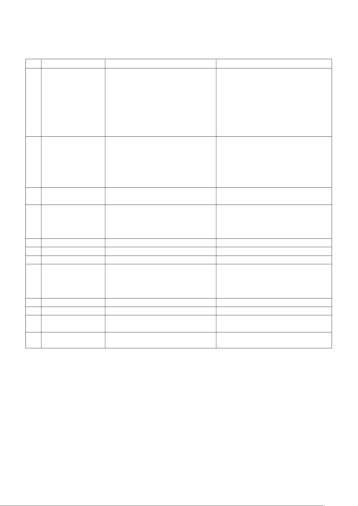
V Model General Specification
No Item Specification Remarks
1 Market Albania, Austria, Belgium, Bosnia, Bulgaria, 36 Country
Coratia, Czech, Denmark, Estonia, Finland,
France, Germany, Greece, Hungary, Ireland,
Italy, Kazakhstan, Latvia, Lithuania,
Luxembourg, Morocco, Netherlands, Norway,
Poland, Portugal, Romania, Russia, Serbia,
Slovenia, Spain, Sweden, Slovakia,
Switzerland, Turkey, Ukraine, UK
2 Broadcasting system 1) PAL/SECAM BG EU (PAL Market)
2) PAL/SECAM DK
3) PAL Ⅰ/Ⅱ
4) SECAM L/L’
5) DVB T
6) DVB C
3 Receiving system Analog : Upper Heterodyne
Digital : COFDM, QAM
4 Scart Jack (2EA) PAL, SECAM Scart 1 Jack is Full scart and support
RF-OUT(Analoge)
Scart 2 jack is Half scart and support
MNT-OUT.
5 Video Input (1EA) PAL, SECAM, NTSC Side AV except PJ20, PK20
6 Component Input (1EA) Y/Cb/Cr, Y/ Pb/Pr rear
7 RGB Input RGB-PC Analog (D-Sub 15Pin) except PJ20, PK20
8 HDMI Input (4EA) HDMI-PC HDMI1/DVI, HDMI2, HDMI3
HDMI-DTV 1ea : PJ20
2ea : PK30, PK20, PJ60, PJ50, PJ30
3ea : PK50, PK70
9 Audio Input (3 EA) RGB/DVI Audio, Component, AV L/R Input
10 SPDIF Out(1 EA) SPDIF Out
11 USB For SVC, S/W Download, X-Studio, DivX PJ30 doesn’t support Divx
PK20, PJ20 only for SVC
12 Bluetooth Bluetooth Phone(JPEG, MP3), Only 50/60PK550
Bluetooth Headset(mono, stereo) Profile : A2DP, BIP, FTP, GAVDP, HSP, OPP
- 6 -
LGE Internal Use OnlyCopyright ©2010 LG Electronics Inc. All rights reserved.
Only for training and service purposes
V Chroma & Brightness (Optical)
(1) (With 38 % Glass Filter) 42T1 module
No Item Min Typ Max Unit Remark
1. White peak brightness 315 - cd/m
2
(*) Peak Brightness Mode
-1/100 white Window pattern
(Typically 1% Window size)
-100IRE (255Gray)
-Picture: Vivid (Medium)
-Input: HDMI-PC(1920*1080 60Hz)
*Peak Brightness Condition may Slightly
different between sets.
148 161 -25/100 white Window pattern
2. White average brightness 46 50 cd/m
2
- 100% Window White Pattern
- 100IRE(255Gray)
- Picture: Vivid(Medium )
3. Brightness uniformity -10 0 +10 %
- 85IRE(216Gray) 100% Window White Pattern
- Picture: Vivid(Medium)
4. Color White X 0.270 0.285 0.300 - White : 85IRE(216Gray) 100% Window
Coordinate Y 0.283 0.293 0.303 White Pattern
Red X 0.635 0.640 - - R/G/B : 100IRE(255Gray) 100% Window
Y 0.318 0.330 0.345 White Pattern
Green X 0.242 0.300 0.305 - Picture: Vivid(Medium )
Y 0.595 0.600 - - 100% Window
Blue X - 0.150 0.158
Y - 0.065 0.075
5. Color coordinate uniformity -0.01 Average +0.01 - 85IRE 100% Window White Pattern
- Picture: Vivid(Medium)
6. Contrast ratio at dark room 100k: 1 1,000k: 1 -1/100 white window pattern(Peak mode)
-100IRE(255Gray)
-Picture: Vivid(Medium)
-Input: HDMI-PC (1920*1080 60Hz)
7. Color Cool X 0.261 0.276 0.291 - 85IRE 100% Window White Pattern
Temperature Y 0.268 0.283 0.298 Warm : ColorGamut => WIDE
Medium X 0.270 0.285 0.300 Cool : Color temperature C30
Y 0.278 0.293 0.308 Meduum : Color temperature 0
Warm X 0.298 0.313 0.328 Warm : Color temperature W30
Y 0.314 0.329 0.344
- 7 -
LGE Internal Use OnlyCopyright ©2010 LG Electronics Inc. All rights reserved.
Only for training and service purposes
ADJUSTMENT INSTRUCTION
1. Application
This spec. sheet is applied to all of the PD01A chassis.
2. Specification
[Caution: The module keeping condition]
- The module keeping condition: The normal temperature
condition(more than 15 °C)
--> Immediately the line supply.
- The module keeping condition: 0 °C
--> The module must be kept for more than 2 hours at the
normal temperature.
- The module keeping condition: -20 °C
--> The module must be kept for more than 3 hours at the
normal temperature.
- The case of Gu-mi factory at the winter season.
--> The module must be kept for more than 5 minutes at
the heating zone(40 °C ~ 45 °C).
(1) The adjustment is according to the order which is
designated and which must be followed, according to the
plan which can be changed only on agreeing.
(2) If there is no specific designation, the adjustment must be
performed in the circumstance of 25 °C ± 5 °C of
temperature and 65 % ± 10 % of relative humidity.
(3) The input voltage of the set must keep 100 V ~ 240 V,
50 / 60 Hz.
(4) Input signal Unit: Product Specification Standard.
(5) The set must be operated for about 5 minutes prior to the
adjustment.
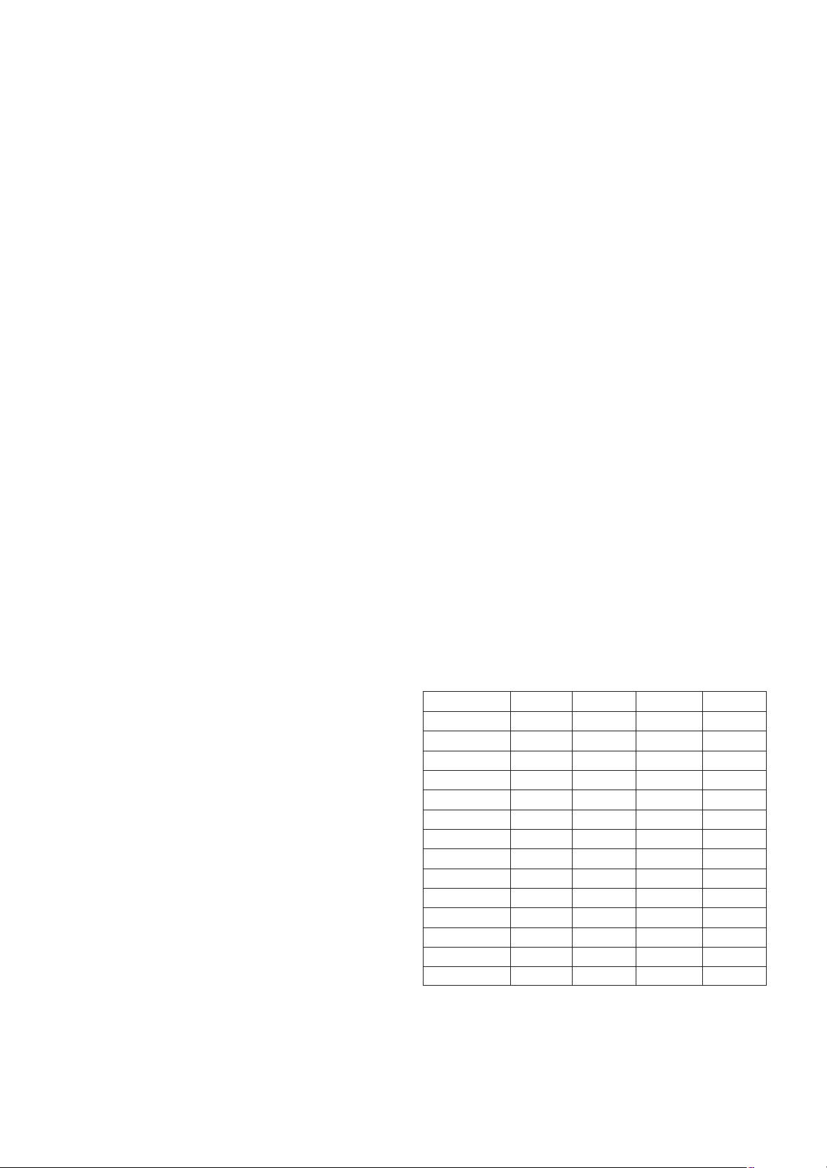
O After turning on RGB Full Window pattern in HEAT-RUN
Mode, the receiver must be operated.
O Enter into HEAT-RUN MODE
1) Press the ‘POWER ON’ button on R/C for adjustment.
2) Press the ‘ADJ’ button on R/C and enter EZ ADJUST
Select “7. Test Pattern” by using
D/E(CH +/-) and press
ENTER(
V)
Select “White” by using
F /G (VOL +/-) and press
ENTER(
V)
- Set heat run should be activated without a signal generator.
- Single color patterns (RED / BLUE / GREEN) of HEAT RUN
MODE are used to check a plasma panel.
- Caution: If you turn on a still screen more than 20 minutes
(Especially digital pattern, cross hatch pattern), an after
image may be made in the black level part of the screen.
[Caution]
- Use ‘power on’ button of a service R/C to power on TV set.
- Do not connect any external input cable if there is no any
specifics.
3. Update S/W using Auto Download
through the USB
Caution: S/W version of USB file (xxx.epk) must be bigger than
one which is downloaded previously.
(1) Insert the USB stick to the USB socket
(2) A d ownloaded file in USB stick will be detected
automatically.
(3) If S/W version of USB file (xxx.epk) is bigger than one
which is downloaded previously, the message, “Copying
files from memory”, will appear.
(4) If an update procedure was completed, TV set will be
turned off and on automatically.
(5) If TV set is turned on, check an updated version.
* If a downloaded version is more bigger than one of which
TV set had, TV set can lost channel data. In this case,
you have to scan channels again.
4. After Downloading S/W, Adjust
TOOL OPTION
(1) Push “IN-START” button on a service R/C.
(2) Select “Tool Option 1” and Push “OK” button.
(3) Put the number of a below table in order of a suffix of the
“Tool Option(X)”.
(Each model has a different number.)
Model
Tool Option1 Tool Option2 Tool Option3 Tool Option4
42PJ250-ZC 25088 546 2252 3360
42PJ350-ZA 25024 1574 35020 3360
42PJ550-ZD 24960 1574 51404 3360
42PJ650-ZA 24896 1574 51408 3360
50PJ250-ZC 37376 546 2252 3360
50PJ350-ZA 37312 1574 35020 3360
50PJ550-ZD 37248 1574 51404 3360
50PJ650-ZA 37184 1574 51408 3360
50PK250-ZA 37120 1570 2252 3360
50PK350-ZB 37056 1574 51404 3360
50PK550-ZE 36992 2598 55500 11552
50PK750-ZA 36928 2598 51408 11552
60PK250-ZA 49408 1570 2252 3360
60PK550-ZE 49280 2598 55500 11552
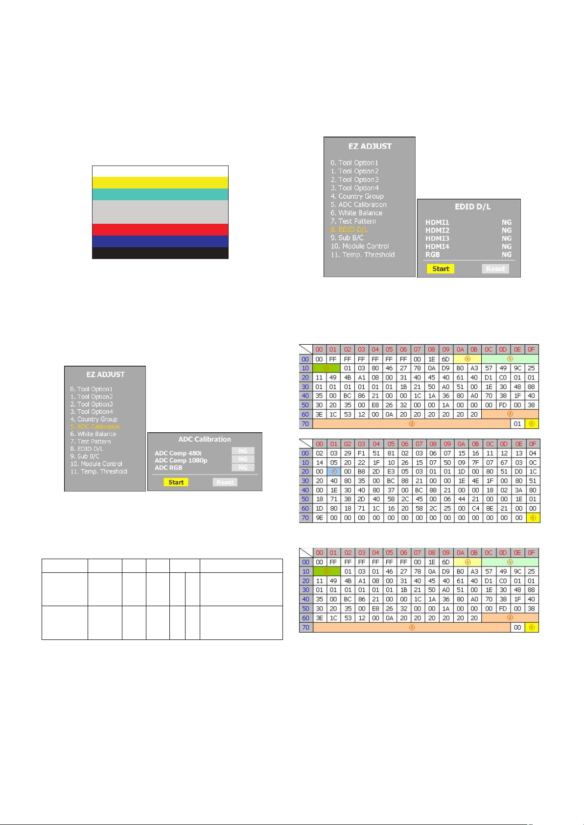
5. ADC Calibration Procedure
(1) Input the component (480i/Horizontal Color Bar) signal to a
TV set.
1) Input Signal Timing : Component 480i
(Other external connection is unnecessary except the
component before executing ADC calibration.)
2) Input Signal Pattern
@ MODEL: 209 in Pattern Generator(480i Mode)
@ PATTERN : 65 in Pattern Generator(MSPG-925
SERISE)
(2) Push “ADJ” button on a service R/C.
(3) Enter internal ADC mode by selecting ‘5. ADC Calibration’.
(4) If you select ‘Start’ on a dialog box of the screen, ADC
calibration will be begun.
Caution: Don’t connect any external input cable except the
component input(480i/Horizontal_Color_Bar) to adjust
ADC calibration
O Auto ADC Calibration Map(RS-232C)
# Adjust Sequence
- aa 00 00 [Enter Adjust Mode]
- xb 00 40 [Component1 Input (480i)]
- ad 00 10 [Adjust 480i Comp1]
- xb 00 60 [RGB Input (1024*768)]
- ad 00 10 [Adjust 1024*768 RGB]
- aa 00 90 End Adjust mode
6. EDID Download Procedure
(1) Push “ADJ” button on a service R/C.
(2) Enter EDID auto download mode by selecting ‘8. EDID
D/L’.
(3) If you select ‘Start’ on a dialog box of the screen, EDID
download will be begun automatically.
(4) Press ‘EXIT’ button on a service R/C.
(5) EDID Data
1) HDMI (HD Models, 256 bytes)
2) RGB (HD Models, 128 bytes)
O EDID Data detailing (ⓐ, ⓑ, ⓒ, ⓓ, ⓔ, ⓕ)
- 8 -
LGE Internal Use OnlyCopyright ©2010 LG Electronics Inc. All rights reserved.
Only for training and service purposes
<Horizontal Color Bar pattern>
NO Item
CMD1
AA00
01
D
A
CMD2 Data0
Enter
Adjust MODE
Adjust
‘Mode In’
When transfer the ‘Made
In’, Carry the command.
Automatically adjustment
(The use of a internal
pattern)
ADC
Adjust
ADC Adjust
ⓐ Product ID
ⓑ Serial No
=> Controlled on production line
ⓒ Month, Year
=> Controlled on production line:
ⓓ Model Name
ⓔ Checksum
=> Changeable by total EDID data
ⓕ HDMI Port No.
O Auto EDID Download Map(RS-232C)
7. PCMCIA CARD Check
You must adjust DTV 29 Channel and insert PCMCIA CARD
to socket.
- If PCMCIA CARD works normally, video signals will appear
on screen.
But it works abnormally, “No CA module” will appear on
screen.
[ Caution: Set up “RF mode” before launching products.
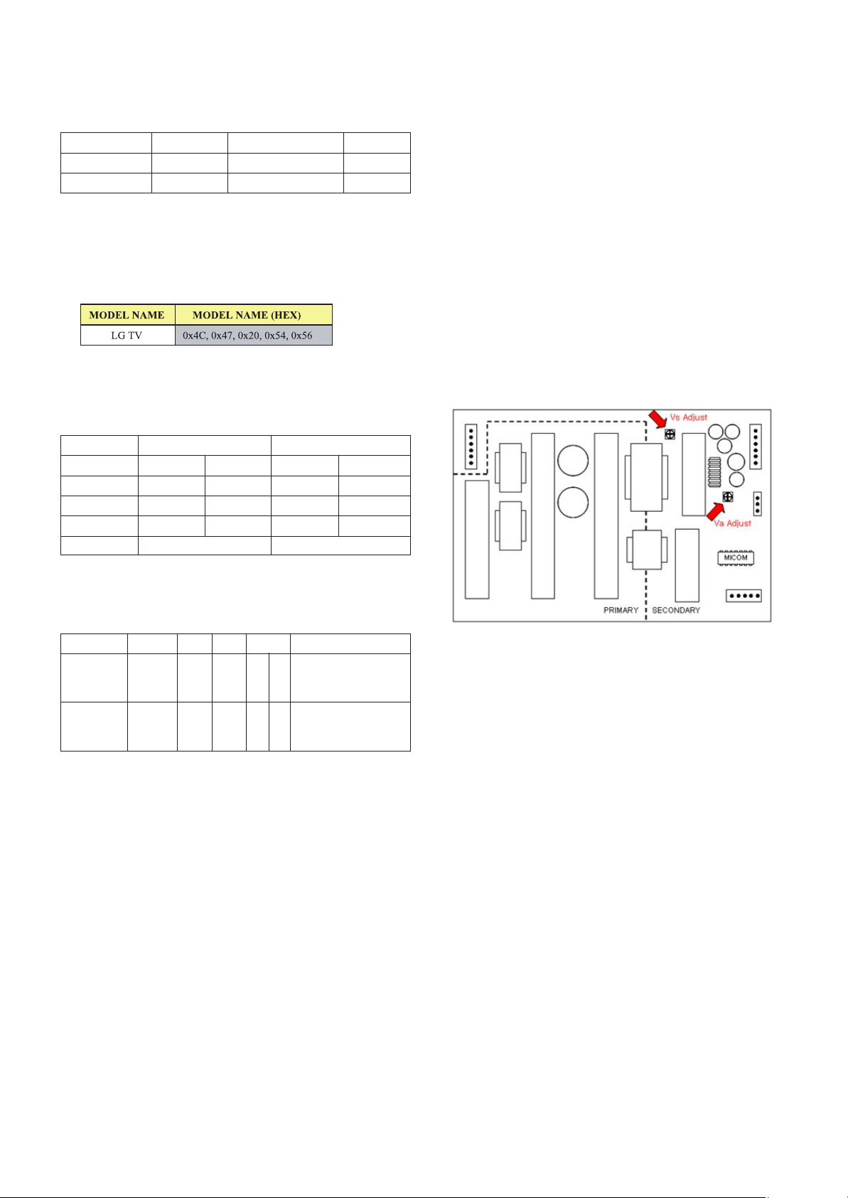
8. POWER Supply Unit PCB Ass’y
Va/Vs Voltage Adjustment
Caution: Both Vs and Va voltage adjustment are necessary.
8-1. Model name:
42PJ250-ZC, 42PJ350-ZA, 42PJ550-ZD, 42PJ650-ZA
50PJ250-ZC, 50PJ350-ZA, 50PJ550-ZD, 50PJ650-ZA
50PK250-ZA, 50PK350-ZB, 50PK550-ZE, 50PK750-ZA
60PK250-ZA, 60PK550-ZE
8-2. Va/Vs Adjustment Procedure
(1) Connect positive(+) terminal of DMM to Vs/Va pin, connect
negative(-) terminal to GND.
(2) Turning ‘Vs/Va Adjust’ and adjust Vs/Va voltages to a
value which is written on a right/top label of a module.
(deviation ; ±0.5V)
[Caution]
- Each Power Supply Unit PCB assembly must be checked by
check JIG set. (Because power PCB Ass’y damages to PDP
Module, especially be careful)
- Set up “RF mode(noise)” before a voltage adjustment.
- Test equipment: DMM 1EA
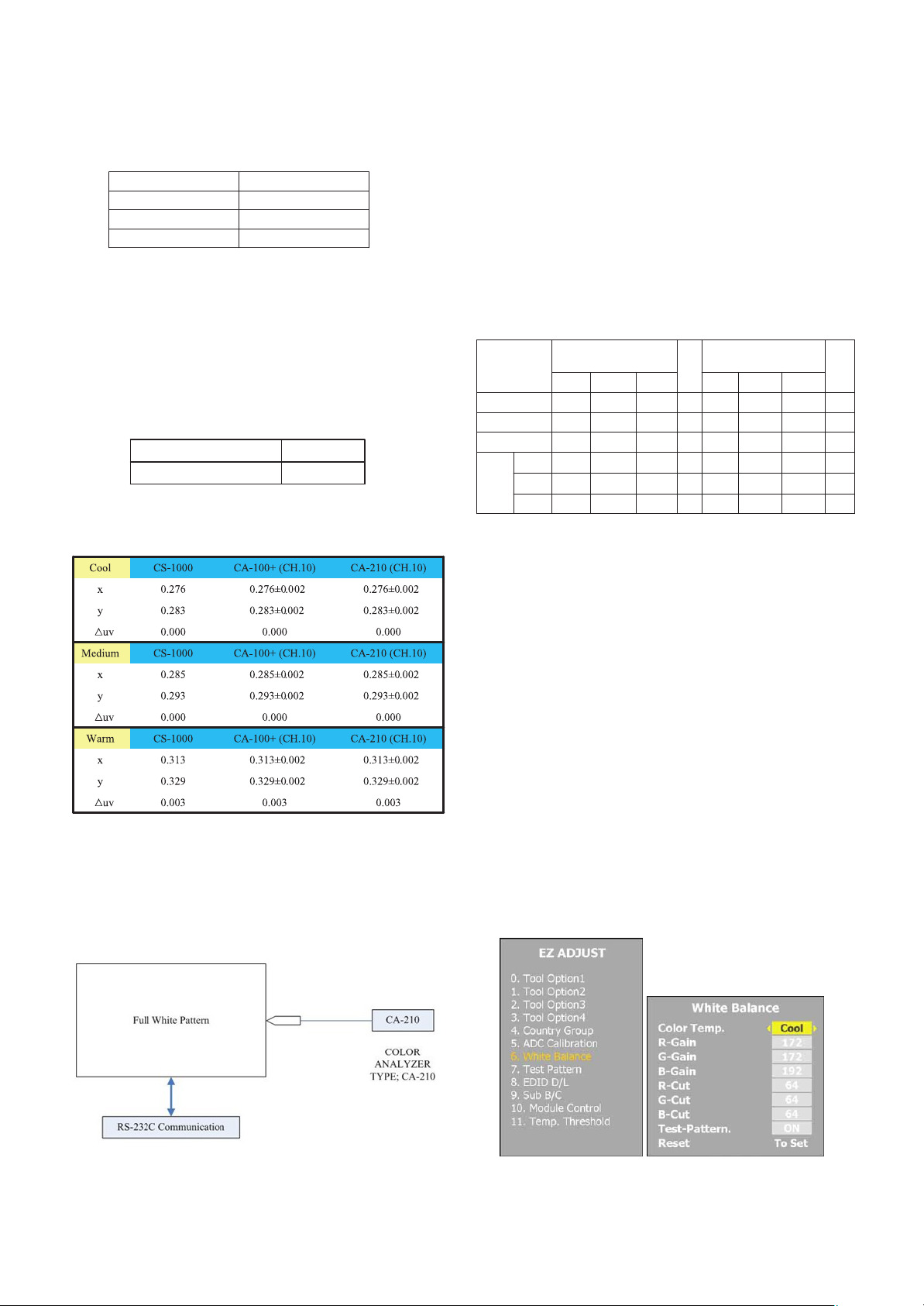
9. White Balance Adjustment
Caution: Press the POWER ON KEY on R/C before W/B
adjustment.
O Test Equipment
Color Analyzer (CS-1000, CA-100+(CH.10), CA-210(CH.10))
O Please adjust CA-100+ / CA-210 by CS-1000 before
measuring
You should use Channel 10 which is Matrix compensated
(White, Red, Green, Blue revised) by CS-1000 and adjust
in accordance with White balance adjustment coordinate.
- 9 -
LGE Internal Use OnlyCopyright ©2010 LG Electronics Inc. All rights reserved.
Only for training and service purposes
NO Item
CMD1
AA00
1000
E
A
CMD2 Data0
Enter
download
MODE
Download
‘Mode In’
When transfer the ‘Made
In’, Carry the command.
Automatically download
(The use of a internal
Data)
Download
EDID data and
Model option
download
MODEL
EDID MODEL
PRODUCT_ID FUNCTION
ALL Model LG DTV 0001(0x01, 0x00) Analog
ALL Model LG DTV 0001(0x01, 0x00) Digital
FHD HD
HDMI1 0xE2 0xB4 0xAF 0xB4
HDMI2 0xE2 0xA4 0xAF 0xA4
HDMI3 0xE2 0x94 0xAF 0x94
HDMI4 - - - -
RGB 0x62 0x2F
9-1. Color Temperature Standards According
to CSM and Module(TBD)
9-2. Change Target Luminance and Range
of the Auto Adjustment W/B Equipment
- 42PJ250-ZC(42T1), 42PJ350-ZA(42T1),
42PJ550-ZD(42T1), 42PJ650-ZA(42T1),
- 50PJ250-ZC(50T1), 50PJ350-ZA(50T1),
50PJ550-ZD(50T1), 50PJ650-ZA(50T1)
- 50PK250-ZA(50R1), 50PK350-ZB(50R1),
50PK550-ZE(50R1), 50PK750-ZA(50R1)
- 60PK250-ZA(60R1), 60PK550-ZE(60R1)
9-3. White Balance Adjustment Coordinate
and Color Temperature
[ PC (for communication through RS-232C) ? UART Baud
rate : 115200 bps
9-4. Automatic W/B Adjustment
(1) Internal PATTERN should be used when W/B is adjusted.
Connect to auto controller like below.
(2) Start White-Balance adjustment, then the full white window
pattern will appear on the screen.
(3) Adjust in the place where the influx of light like floodlight
around is blocked.
(illumination is less than 10ux).
(4) Measure and adjust after sticking the Color Analyzer (CA-
100+, CA210 ) to the side of the module.
O Auto W/B Adjustment Map(RS-232C)
RS-232C COMMAND
[ CMD ID DATA ]
Wb 00 00 White Balance Start
Wb 00 FF White Balance End
9-5. Manual W/B Adjustment
(1) Execute the zero calibration of CA-100+ / CA-210.
(2) Press the ‘ADJ’ button on a service R/C and enter EZ
ASJUST by selecting ‘6. White Balance’.
(3) Then, 216 gray pattern will appear on the screen.
(4) Change the R/G/B-Gain as passing in 3 color coordinates
and temperatures, COOL, MEDIUM and WARM.
< Temperature: COOL >
- R-Cut / G-Cut / B-Cut is set to 64
- Control R-Gain and G-Gain.
- Each gain is limited to 192
< Temperature: MEDIUM >
- R-Cut / G-Cut / B-Cut is set to 64
- Control R-Gain and G-Gain.
- Each gain is limited to 192
< Temperature: WARM >
- R-Cut / G-Cut / B-Cut is set to 64
- Control G-Gain and B-Gain.
- Each gain is limited to 192
(5) Press ‘EXIT’ button on a service R/C
- 10 -
LGE Internal Use OnlyCopyright ©2010 LG Electronics Inc. All rights reserved.
Only for training and service purposes
20Range
50Target luminance
128646464B Cut
128646464G Cut
128646464R Cut
50H3
60H3
25519219219200jfJcjiB Gain
25519219219200jeJbjhG Gain
25519219219200jdJajgR Gain
WarmMedCoolWarmMedCool
MAX
CENTER
(DEFAULT)
Min
RS-232C COMMAND
[CMD ID DATA]
6500KWarm
9300KMedium
11000KCool
PLASMACSM
<Notice> Module Heat-Run Condition for W/B
(1) The adjustment must be performed in the circumstance of
25 °C ± 5 °C of temperature and 65 % ± 10 % of relative
humidity if there is no any specifics.
(2) Before an W/B adjustment, the module which will be used
should be placed in the circumstance of 15 °C ~ 25 °C for
above 2 hours.
(3) If a module was placed in the circumstance of below 15
°C, it should be placed in the circumstance of 15 °C ~ 25
°C for above 2 hours or be run for above 5 minutes in an
aging environment of 60 °C.
(4) Before an W/B adjustment, TV set should be run for 5
minutes at least.
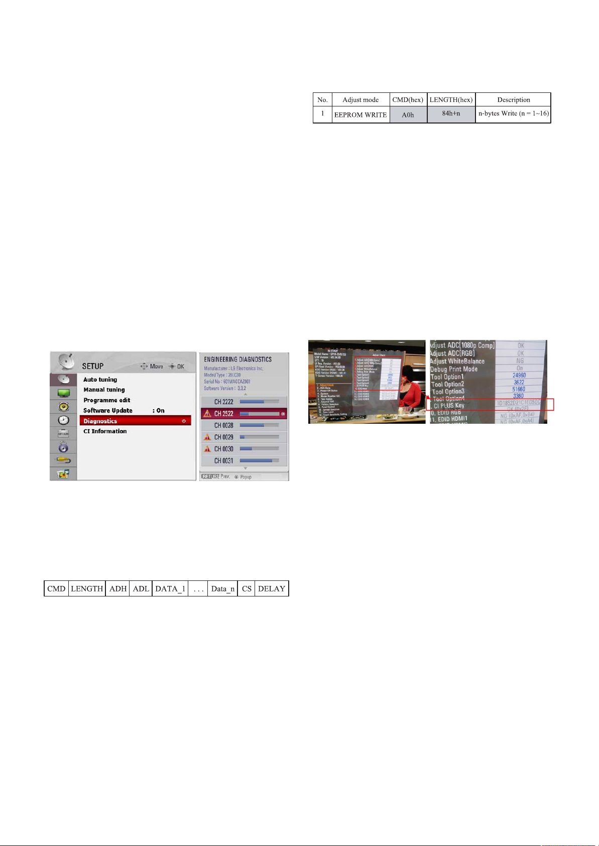
10. Serial Number Download
10-1. Download Procedure
(1) Press “Power on” button of a service R/C.(Baud rate :
115200 bps)
(2) Connect RS232-C Signal Cable.
(3) Write Serial number through RS-232C.
(4) Check the serial number at the Diagnostics of ‘SETUP’
menu. (Refer to below).
Caution : Don’t download HDMI/RGB EEPROM to write a
model name. Model name dois unnecessary
because this model use ‘Tool Option’ to call a model
name.
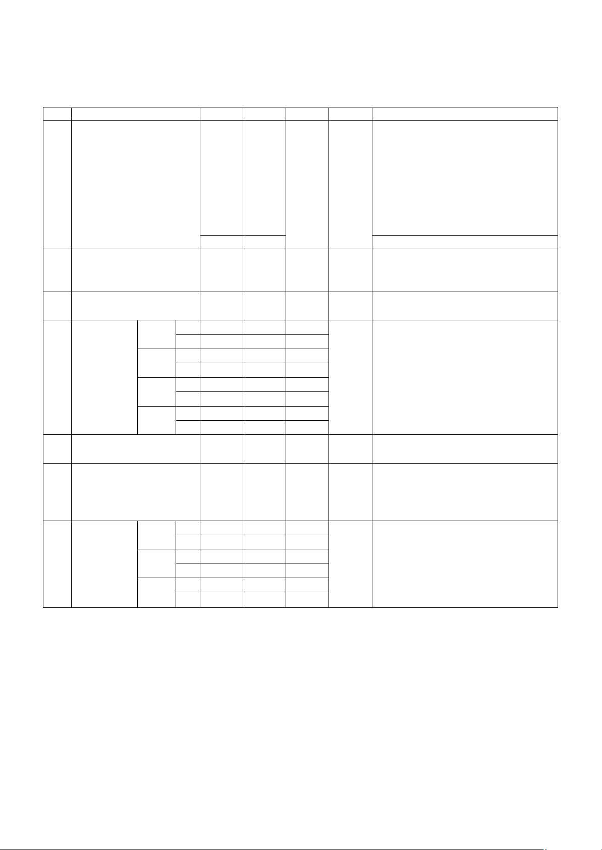
10-2. Signal TABLE
CMD : A0h
LENGTH : 85~94h (1~16 bytes)
ADH : EEPROM Sub Address high (00~1F)
ADL : EEPROM Sub Address low (00~FF)
Data : Write data
CS : CMD + LENGTH + ADH + ADL + Data_1 + ... +
Data_n
Delay : 20ms
10-3. Command Set
[Description]
FOS Default write : <7mode data> write
Vtotal, V_Frequency, Sync_Polarity, Htotal, Hstart, Vstart,
0, Phase
Data write : Model Name and Serial Number write in
EEPROM,.
11. CI+ Key Download
11-1. Download Procedure
(1) Press "Power on" button of a service R/C.(Baud rate :
115200 bps)
(2) Connect RS232-C Signal Cable.
(3) Write CI+ Key through RS-232-C.
(4) Check whether the key was downloaded or not at ‘In Start’
menu. (Refer to below)
12. Check Information
(Serial No. & Model name)
(1) Push the menu button in DTV mode.
(2) Select the SETUP -> Diagnostics -> To set
(3) Check the Serial Number
- 11 -
LGE Internal Use OnlyCopyright ©2010 LG Electronics Inc. All rights reserved.
Only for training and service purposes
 Loading...