

LG 42PA4520, 60PA6550, 60PA6500, 60PA6500-UG, 60PA6550-UM Service Manual
...
North/Latin America http://aic.lgservice.com
Europe/Africa http://eic.lgservice.com
Asia/Oceania http://biz.lgservice.com
Internal Use Only
Printed in KoreaP/NO : MFL67483102 (1205-REV00)
PLASMA TV
SERVICE MANUAL
CHASSIS : PA23A
MODEL : 42PA4500 42PA4500-TM
MODEL : 42PA4520 42PA4520-TJ
CAUTION
BEFORE SERVICING THE CHASSIS,
READ THE SAFETY PRECAUTIONS IN THIS MANUAL.

- 2 -
LGE Internal Use OnlyCopyright © LG Electronics. Inc. All rights reserved.
Only for training and service purposes
CONTENTS
CONTENTS .............................................................................................. 2
SAFETY PRECAUTIONS ........................................................................ 3
SPECIFICATION ....................................................................................... 4
ADJUSTMENT INSTRUCTION ................................................................ 6
BLOCK DIAGRAM .................................................................................. 13
EXPLODED VIEW .................................................................................. 14
SCHEMATIC CIRCUIT DIAGRAM ..............................................................
- 3 -
LGE Internal Use OnlyCopyright © LG Electronics. Inc. All rights reserved.
Only for training and service purposes
Many electrical and mechanical parts in this chassis have special safety-related characteristics. These parts are identified by in the
Schematic Diagram and Exploded View.
It is essential that these special safety parts should be replaced with the same components as recommended in this manual to prevent
Shock, Fire, or other Hazards.
Do not modify the original design without permission of manufacturer.
General Guidance
An isolation Transformer should always be used during the
servicing of a receiver whose chassis is not isolated from the AC
power line. Use a transformer of adequate power rating as this
protects the technician from accidents resulting in personal injury
from electrical shocks.
It will also protect the receiver and it's components from being
damaged by accidental sh orts of the cir cui try that may be
inadvertently introduced during the service operation.
If any fuse (or Fusible Resistor) in this TV receiver is blown,
replace it with the specified.
When replacing a high wattage resistor (Oxide Metal Film Resistor,
over 1 W), keep the resistor 10 mm away from PCB.
Keep wires away from high voltage or high temperature parts.
Before returning the receiver to the customer,
always perform an AC leakage current check on the exposed
metallic parts of the cabinet, such as antennas, terminals, etc., to
be sure the set is safe to operate without damage of electrical
shock.
Leakage Current Cold Check(Antenna Cold Check)
With the instrument AC plug removed from AC source, connect an
electrical jumper across the two AC plug prongs. Place the AC
switch in the on position, connect one lead of ohm-meter to the AC
plug prongs tied together and touch other ohm-meter lead in turn to
each exposed metallic parts such as antenna terminals, phone
jacks, etc.
If the exposed metallic part has a return path to the chassis, the
measured resistance should be between 1 M
Ω and 5.2 MΩ.
When the exposed metal has no return path to the chassis the
reading must be infinite.
An other abnormality exists that must be corrected before the
receiver is returned to the customer.
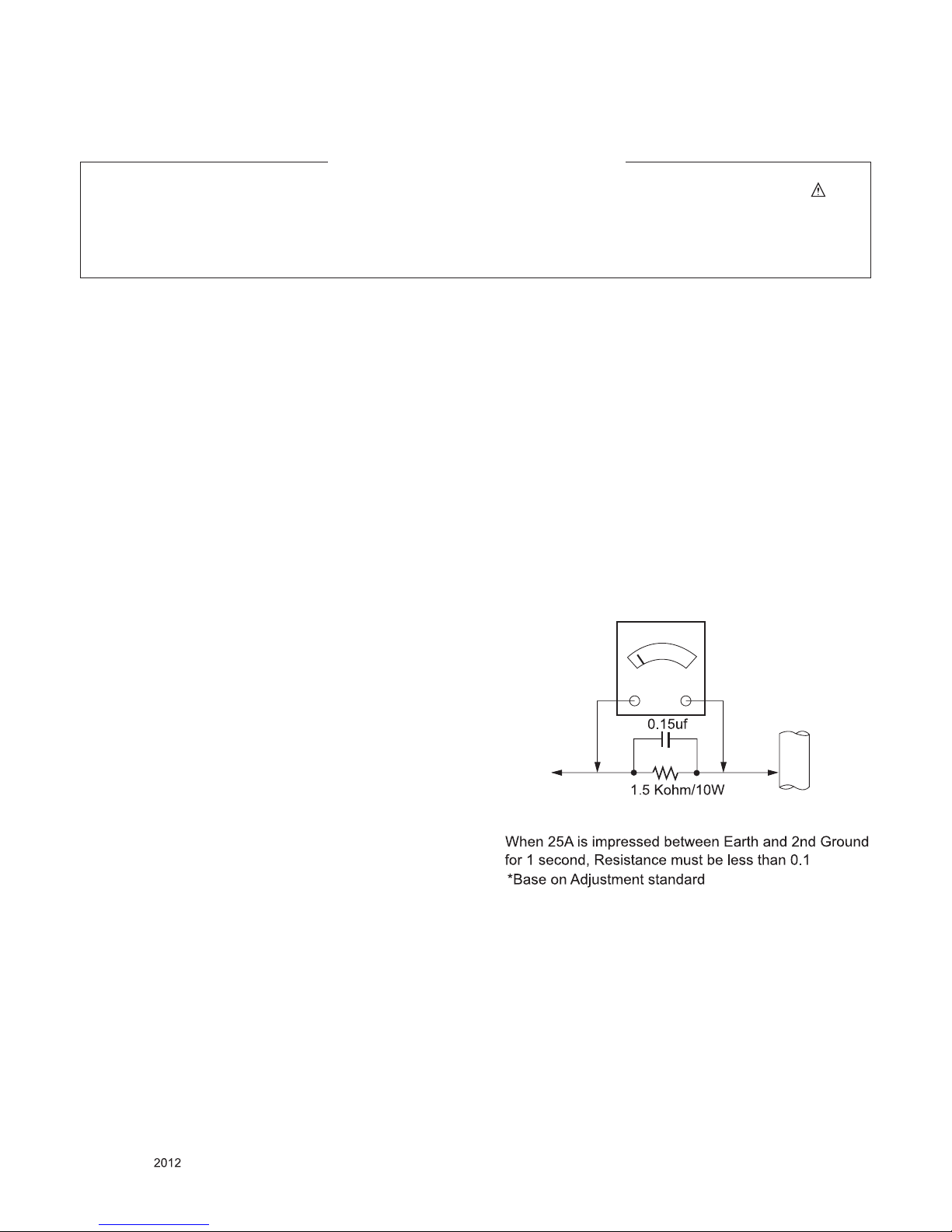
Leakage Current Hot Check (See below Figure)
Plug the AC cord directly into the AC outlet.
Do not use a line Isolation Transformer during this check.
Connect 1.5 K / 10 watt resistor in parallel with a 0.15 uF capacitor
between a known good earth ground (Water Pipe, Conduit, etc.)
and the exposed metallic parts.
Measure the AC voltage across the resistor using AC voltmeter
with 1000 ohms/volt or more sensitivity.
Reverse plug the AC cord into the AC outlet and repeat AC voltage
measurements for each exposed metallic part. Any voltage
measured must not exceed 0.75 volt RMS which is corresponds to
0.5 mA.
In case any measurement is out of the limits specified, there is
possibility of shock hazard and the set must be checked and
repaired before it is returned to the customer.
Leakage Current Hot Check circuit
IMPORTANT SAFETY NOTICE
To Instrument's
exposed
METALLIC PARTS
Good Earth Ground
such as WATER PIPE,
CONDUIT etc.
AC Volt-meter
SAFETY PRECAUTIONS
- 4 -
LGE Internal Use OnlyCopyright © LG Electronics. Inc. All rights reserved.
Only for training and service purposes
SPECIFICATION
NOTE : Specifications and others are subject to change without notice for improvement
.
1. Application range
This spec sheet is applied all of the PDP TV with PA23A chassis.
2. Requirement for Test
Each part is tested as below without special appointment.
(1) Temperature: 25 °C ± 5 °C(77 °F ± 9 °F), CST: 40 °C ± 5 °C
(2) Relative Humidity: 65 % ± 10 %
(3) Power Voltage
: Standard input voltage (AC 100-240 V~, 50/60 Hz)
* Standard Voltage of each products is marked by models.
(4) Specification and performance of each parts are followed each drawing and specification by part number in accordance with
BOM.
(5) The receiver must be operated for about 5 minutes prior to the adjustment.
3. Test method
(1) Performance: LGE TV test method followed
(2) Demanded other specification
- Safety : CE, IEC specification
- EMC : CE, IEC
4. Module General Specification
- 42" 2D HD
No Item Specication Remark
1 Display Screen Device 106 cm (42 inch) wide Color Display Module PDP
2 Aspect Ratio 16:9
3 PDP Module PDP42T4####,
RGB Closed (Well) Type, Glass Filter (38%)
Pixel Format: 1024 horiz. By 768 ver.
4 Operating Environment 5) Temp. : 0 ~ 40 deg
6) Humidity : 20 ~ 80%
LGE SPEC
5 Storage Environment 7) Temp. : -20 ~ 60 deg
8) Humidity : 10 ~ 90 %
6 Input Voltage AC100 ~ 240V, 50/60Hz Maker LG
- 5 -
LGE Internal Use OnlyCopyright © LG Electronics. Inc. All rights reserved.
Only for training and service purposes
No Item Specication Remark
1 Market Australia, New Zealand, Indonesia, Malaysia, Singa-
pore, South Africa, Israel, Iran, Vietnam, Myanmar,
Non-EU analog
2 Broadcasting system 1) PAL/SECAM BG
2) PAL/SECAM DK
3) PAL I / II
4) SECAM L/L’
5) DVB T
6) DVB C
EU (PAL Market)
3 Receiving system Analog : Upper Heterodyne
Digital : COFDM
4 Scart Jack (1EA) PAL, SECAM
5 Component Input
(1EA)
Y/Cb/Cr, Y/ Pb/Pr
6 RGB Input (1EA) RGB-PC Analog (D-Sub 15Pin)
7 RS232C (1EA) SVC
8 HDMI Input (2 or 3EA) HDMI-PC
HDMI-DTV
HDMI1/DVI, HDMI2,
HDMI3
9 Audio Input (2EA) RGB/DVI Audio, Component L/R Input
10 SPDIF Out (1 EA) SPDIF Out
11 USB (1EA) for SVC, S/W Download, DivX
12 LAN only DVB-T2 models
13 PCMCI (1EA) DVB-T/C Decryption Interface, CI+
5. Model General Specification
- 6 -
LGE Internal Use OnlyCopyright © LG Electronics. Inc. All rights reserved.
Only for training and service purposes
ADJUSTMENT INSTRUCTION
1. Application Range
This spec. sheet applies to PA23A chassis applied PDP TV all
models manufactured in TV factory.
2. Designation
(1) Th e ad justm ent is accord ing to the order whic h is
designated and which must be followed, according to the
plan which can be changed only on agreeing.
(2) Power adjustment : Free Voltage.
(3) Magnetic Field Condition: Nil.
(4) Input signal Unit: Product Specification Standard.
(5) Reserve after operation: Above 5 Minutes (Heat Run)
Temperature : at 25 °C ± 5 °C
Relative humidity : 65 % ± 10 %
Input voltage : 220V, 60Hz
(6) Adjustment equipment s : Color Ana lyzer (CA -210 or
CA-110), DDC Adjustment Jig equipment, SVC remote
controller.
(7) The receiver must be operated for about 5 minutes prior to
the adjustment when module is in the circumstance of over
15
- In case of keeping module is in the circumstance of 0°C, it
should be placed in the circumstance of above 15°C for 2
hours.
- In case of keeping module is in the circumstance of below
-20°C, it should be placed in the circumstance of above
15°C for 3 hours.
■ After RGB Full White in HEAT-RUN Mode, the receiver must
be operated prior to the adjustment.
■ Enter into HEAT-RUN MODE
1) Press the POWER ON KEY on R/C for adjustment.
2) OSD display and screen display PATTERN MODE.
● Set is activated HEAT run without signal generator in this
mode.
● Single color pattern ( WHITE ) of HEAT RUN MODE uses to
check panel.
● Caution : If you turn on a still screen more than 20 minutes
(Especially digital pattern, cross hatch pattern), an
after image may be occur in the black level part of
the screen.
(8) Push The “IN STOP KEY” – For memory initialization.
3. Main PCB check process
* APC - After Manual-Insult, executing APC
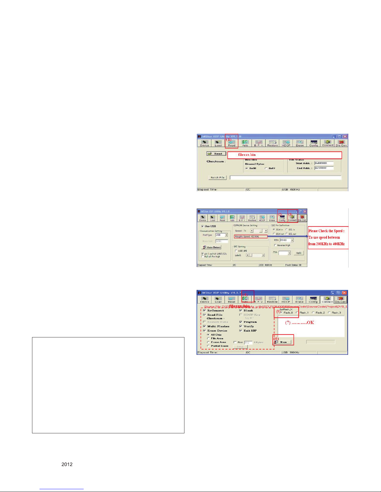
* Boot file Download
(1) Execute ISP program “Mstar ISP Utility” and then click
“Config” tab.
(2) Set as below, and then click “Auto Detect” and check “OK”
message
If “Error” is displayed, Check connection between computer,
jig, and set.
(3) Click “Read” tab, and then load download file (XXXX.bin)
by clicking “Read”
(4) Click “Connect” tab. If “Can’t ” is displayed, Check
connection between computer, jig, and set.
(5) Click “Auto” tab and set as below.
(6) Click "Run".
(7) After downloading, check "OK" message.
Case1 : Software version up
1) After downloading S/W by USB , Multi-vision set will reboot
automatically
2) Push “In-stop” key
3) Push “Power on” key
4) Function inspection
5) After function inspection, Push “In-stop” key.
Case2 : Function check at the assembly line
1) When TV set is entering on the assembly line, Push “In-
stop” ke y at rst.
2) Push “Power on” key for turning it on.
-> If you push “Power on” key, TV set will recover channel
information by itself.
3) After function inspection, Push “In-stop” key.
- 7 -
LGE Internal Use OnlyCopyright © LG Electronics. Inc. All rights reserved.
Only for training and service purposes
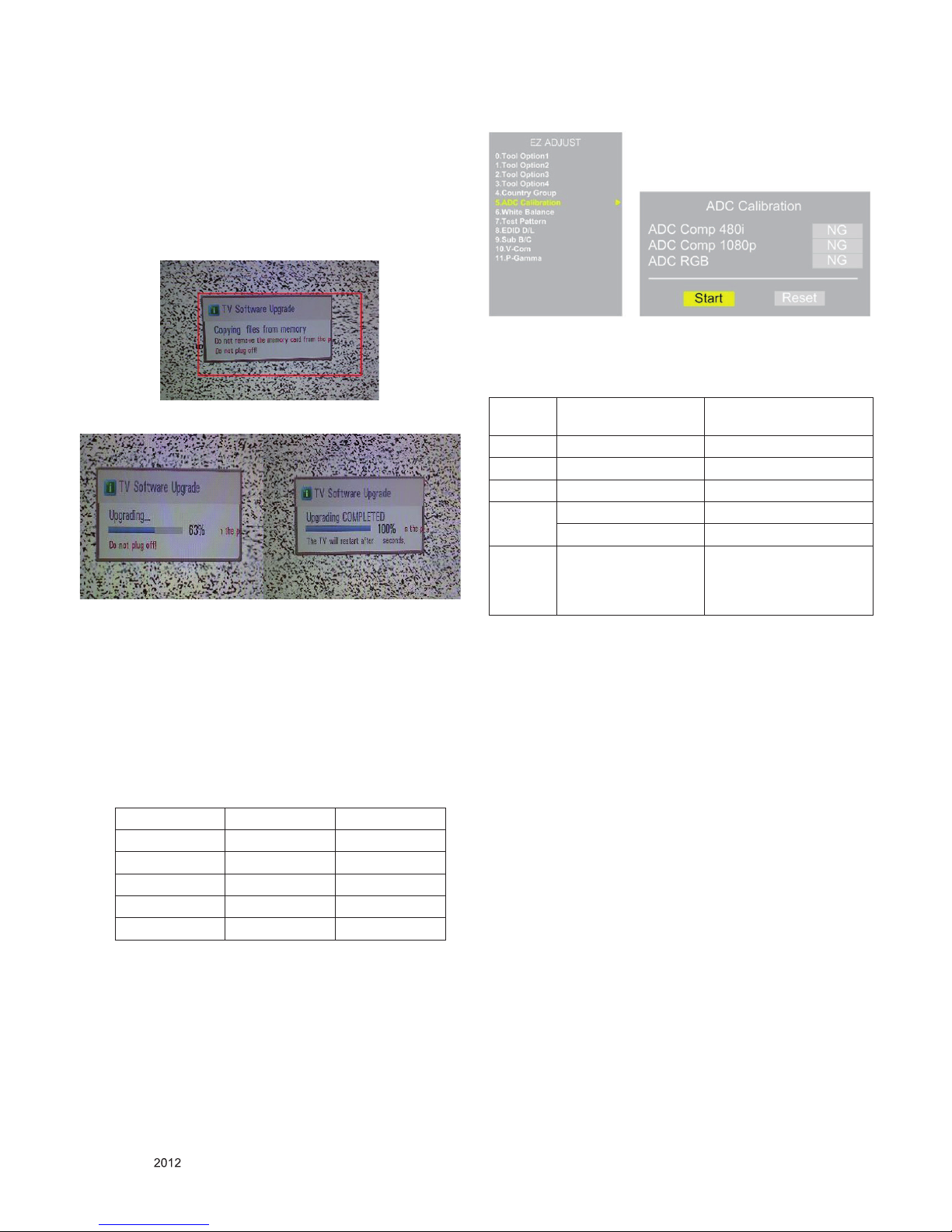
* USB DOWNLOAD(*.epk file download)
(1) Put the USB Stick to the USB socket
(2) Automatically detecting update file in USB Stick
- If your downloaded program version in USB Stick is Low,
it didn’t work.
- But your downloade d version is High, USB data is
automatically detecting
(3) Show the message “Copying files from memory”
(4) Updating is staring.
(5) Updating C om pl et ed, T he Mu lt i- vi si on will restart
automatically.
(6) If your Multi-vision is turned on, check your updated
version and Tool option. (explain the Tool option, next
stage)
* After downloading, have to adjust TOOL OPTION again.
1) Push "IN-START" key in service remote controller.
2) Select "Tool Option 1" and Push “OK” button.
3) Punch in the number. (Each of mode ls has th eir
number.)
4) Completed selecting Tool option.
3.1. ADC Process
3.1.1. ADC
■ Enter Service Mode by pushing “ADJ” key,
■ Enter Internal ADC mode by pushing “►” key at “5. ADC
Calibration”
* Caution : Using ‘power on’ button of the Adjustment R/C ,
power on Multi-vision.
* ADC Calibration Protocol (RS232)
- Adjust Sequence
▪aa 00 00 [Enter Adjust Mode]
▪xb 00 40 [Component1 Input (480i)]
▪ad 00 10 [Adjust 480i Comp1]
▪xb 00 60 [RGB Input (1024*768)]
▪ad 00 10 [Adjust 1024*768 RGB]
▪aa 00 90 End Adjust mode
* Required equipment : Adjustment R/C.
3.2. Function Check
3.2.1. Check display and sound
■ Check Input and Signal items. (cf. work instructions)
1) COMPONENT (480i)
2) RGB (PC : 1024 x 768 @ 60hz)
3) HDMI
4) DVI
5) PC Audio In
* Display and Sound check is executed by Remote control-
ler.
* Caution : Not to push the INSTOP KEY after completion if
the function inspection.
42PA4500-T* 42PA4520-T*
Tool option 1 24576 24672
Tool option 2 22922 39306
Tool option 3 3697 3697
Tool option 4 54342 54342
Tool option 5 10 10
NO Enter
Adjust MODE
ADC adjust
Item Adjust ‘Mode In’ ADC Adjust
CMD 1 A A
CMD 2 A D
Data 0 0 0
1 0
When transfer the
‘Mode In’,
Carry the command.
Automatically adjustment
(The use of a internal
pattern)
- 8 -
LGE Internal Use OnlyCopyright © LG Electronics. Inc. All rights reserved.
Only for training and service purposes
4. Total Assembly line process
4.1. POWER PCB Assy voltage adjustment
(Vs voltage adjustment)
● Required Equipment for adjustment
- D.M.M
● Condition for adjustment
- No signal with the snow noise in RF mode
4.2. Adjustment Preparation
● Required Equipment
- Remote controller for adjustment
- Color Analyzer ( CS-1000, CA-100,100+,CA-210 or same
product : CH 11 (PDP)
* Please adjust CA-210, CA-100+ by CS-1000 before measur-
ing
- Auto W/B adjustment instrument(only for Auto adjust-
ment)
- 9 Pin D-Sub Jack(RS232C) is connected to the AUTO
W/B EQUIPMENT.
Before Adjust of White Balance, Please press
POWER ONLY key
- Adjust Process will start by execute RS232C Command.
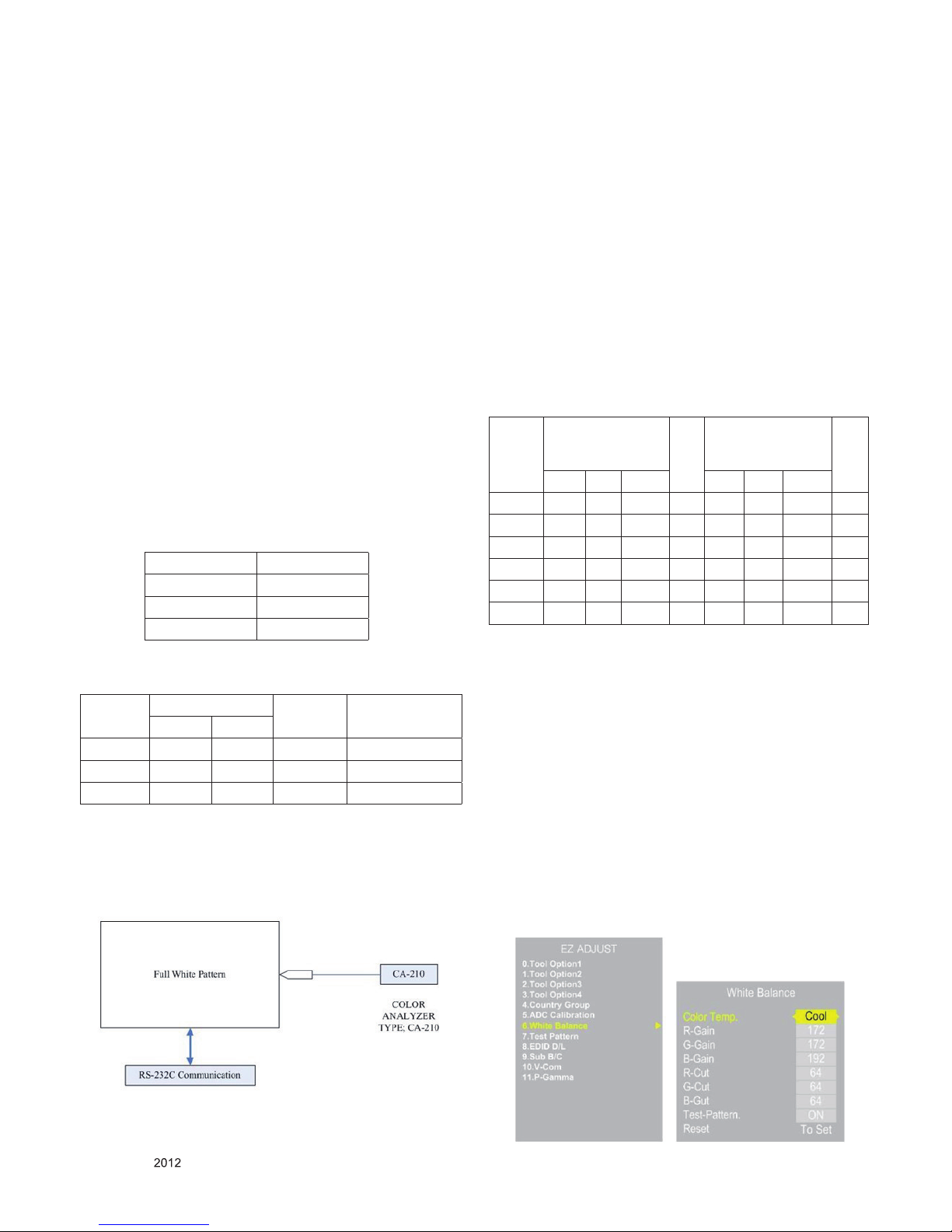
● Color temperature standards according to CSM and Module
● CS-1000/CA-100+/CA-210(CH 10) White balance adjust-
ment coordinates and color temperature.
* Connecting picture of the measuring instrument (On Auto-
matic control)
- Inside PATTERN is used when W/B is controlled. Con-
nect to auto controller or push Adjustment R/C POWERON -> Enter the mode of White-Balance, the pattern will
come out.
* Auto-control interface and directions
1) Adjust in the place where the inux of light like oodlight
around is blocked. (Illumination is less than 100Lux).
2) Adhere closely the Color Analyzer ( CA210 ) to the
module less than 10cm distance, keep it with the surface
of the Module and Color Analyzer’s Prove vertically.
(80~100°).
3) Aging time
- After aging start, keep the power on (no suspension of
power supply) and heat-run over 5 minutes.
- Using ‘no signal’ or ‘full white pattern’ or the others,
check the back light on.
■ Auto adjustment Map(RS-232C)
RS-232C COMMAND
[ CMD ID DATA ]
Wb 00 00 White Balance Start
Wb 00 ff White Balance End
* Caution
- Color Temperature : COOL, Medium, Warm.
- One of R Gain/G Gain/ B Gain should be kept on 0xC0,
and adjust other two lower than C0. (when R/G/B Gain
are all C0, it is the FULL Dynamic Range of Module)
* Manual W/B process using adjusts Remote control.
■ After enter Service Mode by pushing “ADJ” key,
■ Enter White Balance by pushing “►” key at “6. White
Balance”.
■ Stick the sensor to the center of the screen and select
each items(Red/Green/Blue Gain) using ▲/▼(CH +/-)
key on R/C.
■ Adjust R/G/B Gain using◄/►(VOL +/-) key on R/C.
■ Adjust three modes all(Cool/Medium/Warm) : Fix the one
of R/G/B Gain and Change the others.
■ When the adjustment is completed, Enter “COPY ALL”.
■ Exit adjustment mode using EXIT key on R/C.
CSM PLASMA
Cool 11000K
Medium 9300K
Warm 6500K
CSM Color Coordination Temp ± Color
Coordination
x y
COOL 0.276 0.283 11000K 0.002
MEDIUM 0.285 0.293 9300K 0.002
WARM 0.313 0.329 6500K 0.002
RS-232C
COMMAND
[CMD ID DATA]
M
I
N
CENTER
(DEFAULT)
M
A
X
Cool Mid Warm Cool Mid Warm
R Gain jg Ja jd 00 172 192 192 192
G Gain jh Jb je 00 172 192 192 192
B Gain ji Jc jf 00 192 192 172 192
R Cut 64 64 64 128
G Cut 64 64 64 128
B Cut 64 64 64 128
- 9 -
LGE Internal Use OnlyCopyright © LG Electronics. Inc. All rights reserved.
Only for training and service purposes
* After You nish all adjustments, Press “In-start” button and
compare Tool option and Area option value with its BOM, if it
is correctly same then unplug the AC cable.
If it is not same, then correct it same with BOM and unplug
AC cable.
For correct it to the model’s module from factory JIG model.
* Push The “IN STOP KEY” after completing the function
inspection. And Mechanical Power Switch must be set “ON”
* To check the coordinates of White Balance, you have to
measure at the below conditions.
- Picture mode : Vivid, Energy Saving : Off, Below the Ad-
vanced control, Dynamic Contrast : Off, Dynamic Colour : Off
Colour Temp.
-> Picture Mode change : Vivid -> Vivid(User)
4.3. DDC EDID Write (RGB 128Byte)
-> Not used any more, Use Auto D/L
■ Connect D-sub Signal Cable to D-Sub Jack.
■ Write EDID DATA to EEPROM (24C02) by using DDC2B
protocol.
■ Check whether written EDID data is correct or not.
* For SVC main Ass’y, EDID have to be downloaded to Insert
Process in advance.
4.4. DDC EDID Write (HDMI 256Byte)
-> Not used any more, Use Auto D/L
■ Connect HDMI Signal Cable to HDMI Jack.
■ Write EDID DATA to EEPROM(24C02) by using DDC2B
protocol.
■ Check whether written EDID data is correct or not.
* For SVC main Ass’y, EDID have to be downloaded to Insert
Process in advance.
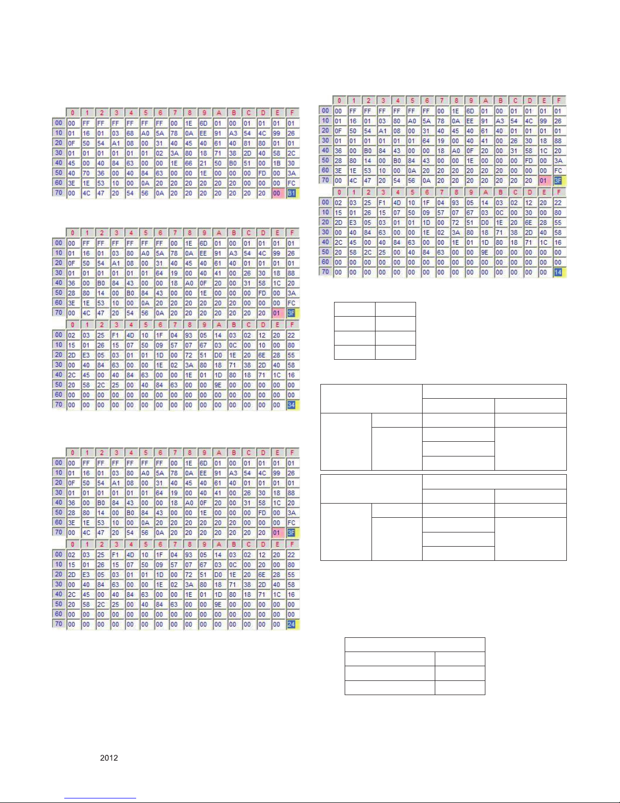
4.5. EDID DATA
(1) All Data : HEXA Value
(2) Changeable Data :
* : Serial No : Controlled / Data:01
** : Month : Controlled / Data:00
*** : Year : Controlled
**** : Check sum
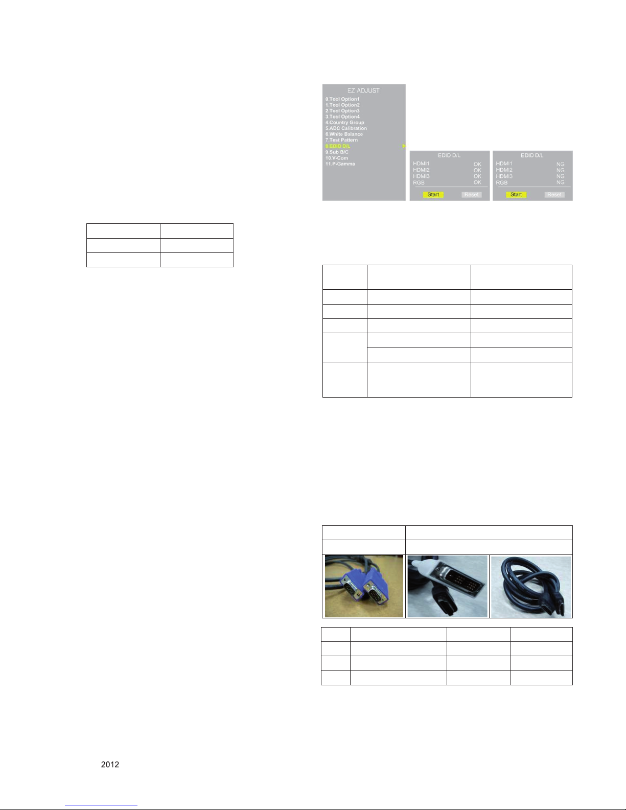
4.6. EDID DATA Auto Download
(1) Press Adj. key on the Adj. R/C,
(2) Select EDID D/L menu.
(3) By pressing Enter key, EDID download will begin
(4) If Download is successful, OK is display, but If Download is
failure, NG is displayed.
(5) If Download is failure, Re-try downloads.
* Caution : Never connect HDMI & D-sub Cable when EDID
downloaded.
■ Edid data and Model option download (RS232)
- Manual Download
* Caution
● Use the proper signal cable for EDID Download
- Analog EDID : Pin3 exists
- Digital EDID : Pin3 exists
* Caution
- Never connect HDMI & D-sub Cable at the same time.
- Use the proper cables below for EDID Writing.
- Download HDMI1, HDMI2 separately because HDMI1 is different from HDMI2.
Cool 30
Medium 0
Warm 30
NO Enter
download MODE
EDID data Model
option download
Item download ‘Mode In’ download
CMD 1 A A
CMD 2 A E
Data 0 0 00
0 10
When transfer the
‘Mode In’,
Carry the command.
Automatically download
(The use of a internal
pattern)
No. Item Condition Hex Data
1 Manufacturer ID GSM 1E6D
2 Version Digital : 1 01
3 Revision Digital : 3 03
For Analog EDID For HDMI EDID
D-sub to D-sub DVI-D to HDMI or HDMI to HDMI
- 10 -
LGE Internal Use OnlyCopyright © LG Electronics. Inc. All rights reserved.
Only for training and service purposes
* 2D HD EDID data
- 2D HD RGB EDID data
- 2D HD HDMI1 EDID data
- 2D HD HDMI2 EDID data
- 2D HD HDMI3 EDID data
* Vender ID
* Checksum: Changeable by total EDID data.
4.7. Checking the EYE-Q Operation.
(1) Press the EYE Key on the adjustment remote controller.
(2) Check the Sensor DATA ( It must be under 10) and keep
the data longer than 1.5s
(3) Check ‘OK’
(Sensor DATA 0 ~ 4095, Power Saving Mode 0 ~ 12)
* IF you press IN-STAP Button, change Green Eye-check
OSD.
Input HEX
HDMI1 10
HDMI2 20
HDMI3 30
EDID C/S data 2D-FHD
HDMI RGB
check sum
(Hex)
Block 0 0x63 0x7C
Block 1 0x76(HDMI1)
0x66(HDMI2)
0x56(HDMI3)
EDID C/S data 2D-HD
HDMI RGB
check sum
(Hex)
Block 0 0x3F 0x58
Block 1 0xFC(HDMI1)
0xEC(HDMI2)
0xDC(HDMI3)
Green Eye-Check(Factory Mode)
Sensor Data 9
Power saving mode 1
OK
- 11 -
LGE Internal Use OnlyCopyright © LG Electronics. Inc. All rights reserved.
Only for training and service purposes
5. Model name & Serial number Download
5.1. Model name & Serial number D/L
■ Press “Power on” key of service remocon.(Baud rate :
115200 bps)
■ Connect RS232 Signal Cable to RS-232 Jack.
■ Write Serial number by use RS-232.
■ Must check the serial number at signal test of customer sup-
port. (Refer to below).
5.2. Signal TABLE
CMD: A0h
LENGTH : 85~94h (1~16 bytes)
ADH : EEPROM Sub Address high (00~1F)
ADL : EEPROM Sub Address low (00~FF)
Data : Write data
CS : CMD + LENGTH + ADH + ADL + Data_1 + … + Data_n
Delay : 20ms
5.3. Command Set
* Description
FOS Default write : <7mode data> write
Vtotal, V_Frequency, Sync_Polarity, Htotal, Hstart, Vstart,
0, Phase
Data write : Model Name and Serial Number write in EEPROM,.
5.4. Method & Notice
(1) Serial number D/L is using of scan equipment.
(2) Setting of scan equipment operated by Manufacturing
Technology Group.
(3) Serial number D/L must be conformed when it is produced
in production line, because serial number D/L is mandatory
by D-book 4.0
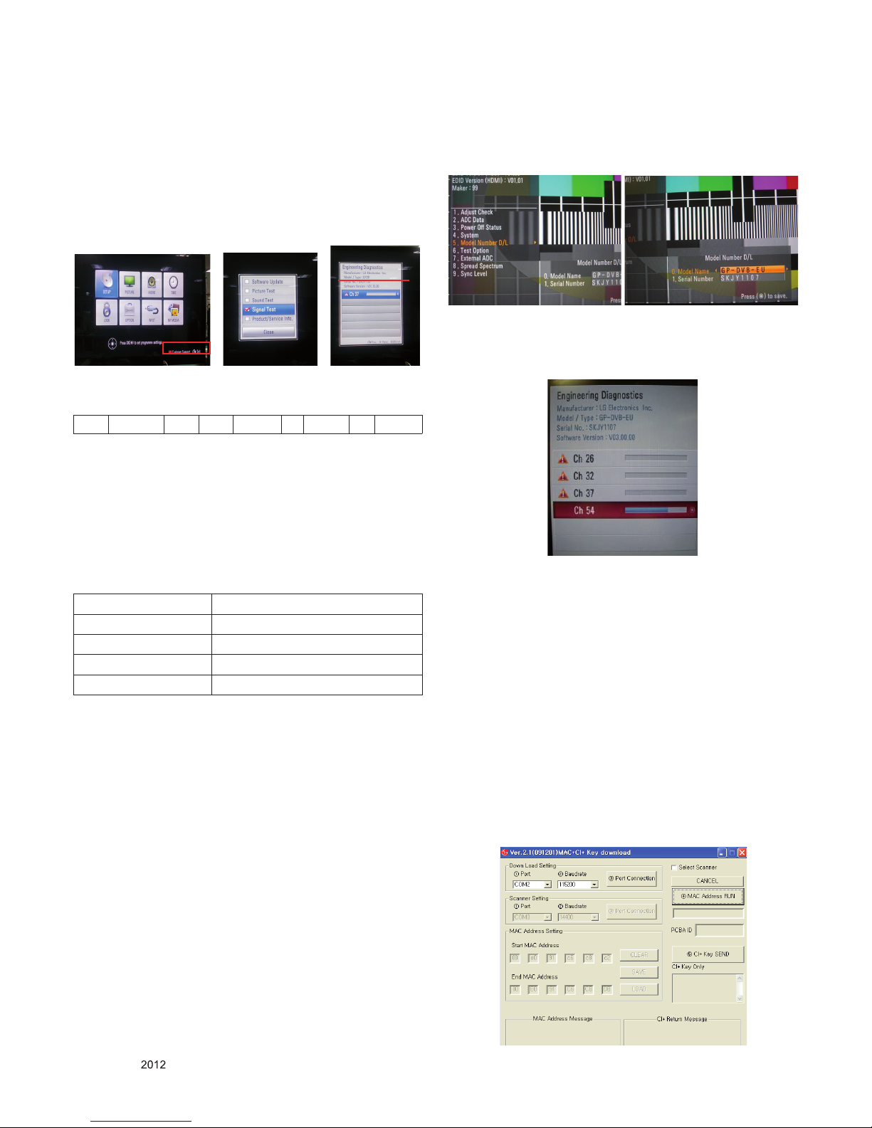
* Manual Download (Model Name and Serial Number)
If the TV set is downloaded By OTA or Service man,
Sometimes model name or serial number is initialized.( Not
always)
There is impossible to download by bar code scan, so It need
Manual download.
1) Press the ‘instart’ key of ADJ remote controller.
2) Go to the menu ‘5.Model Number D/L’ like below photo.
3) Input the Factory model name or Serial number like
photo.
4) Check the model name Instart menu -> Factory name
displayed.
5) Check the Diagnostics (DTV country only) -> Buyer
model displayed
6. Download MAC Address, CI+ Key
and widevine Key.
- Check whether the key was downloaded or not at ‘In Start’
menu. (Refer to below).
-> MAC Address need only DVB-T2 Model (ex.50PA650T-ZA).
* Connect TV SET and PC which download keys Writing
program by RS232C-Cable
1) Start “MAC+CIKeyl.exe”Program and Click (3) Button to
connect TV and PC.
2) Click (4) to download MAC Address.
3) Click (5) to download CI+ Key.
4) When download succeed, you can see “OK” on (6)
* Each Chassis has it’s own MAC Address. Please be careful
of download.
CMD LENGTH ADH ADL DATA_1 ... Data_n
CS DELAY
No. 1
Adjust mode EEPROM WRITE
CMD(hex) A0h
LENGTH(hex) 84h+n
Description n-bytes Write (n = 1~16)

- 12 -
LGE Internal Use OnlyCopyright © LG Electronics. Inc. All rights reserved.
Only for training and service purposes
■ Check the method of RS232C Command
(1) into the main ass’y mode (RS232 : aa 00 00)
(2) ch eck the key downlo ad for transmi tted command
(RS232 : ci 00 10)
(3) result value
- normally status for download : OKx
- abnormally status for download : NGx
7 . SW Download Guide.
* Put a *.bin to USB Stick and Turn on TV
(1) Put the USB Stick to the USB socket
(2) Automatically detecting update le in USB Stick
* If your downloaded program version in USB Stick is Low,
it didn’t work.
But your downloaded version is High, USB data is auto-
matically detecting.
(3) Show the message “Copying les from memory”
(4) Updating is staring.
(5) Updating Completed, The TV will restart automatically.
After turn on TV, Please press ‘IN-STOP’ button on ADJ
Remote-control.
* IF you don’t have ADJ R/C, enter ‘Factory Reset’ in OP-
TION MENU.
(6) When TV turn on, check the Updated version on Diagnos-
tics MENU.
CMD1 CMD2 Data 0
A A 0 0
CMD1 CMD2 Data 0
C 1 1 0
- 13 -
LGE Internal Use OnlyCopyright © LG Electronics. Inc. All rights reserved.
Only for training and service purposes
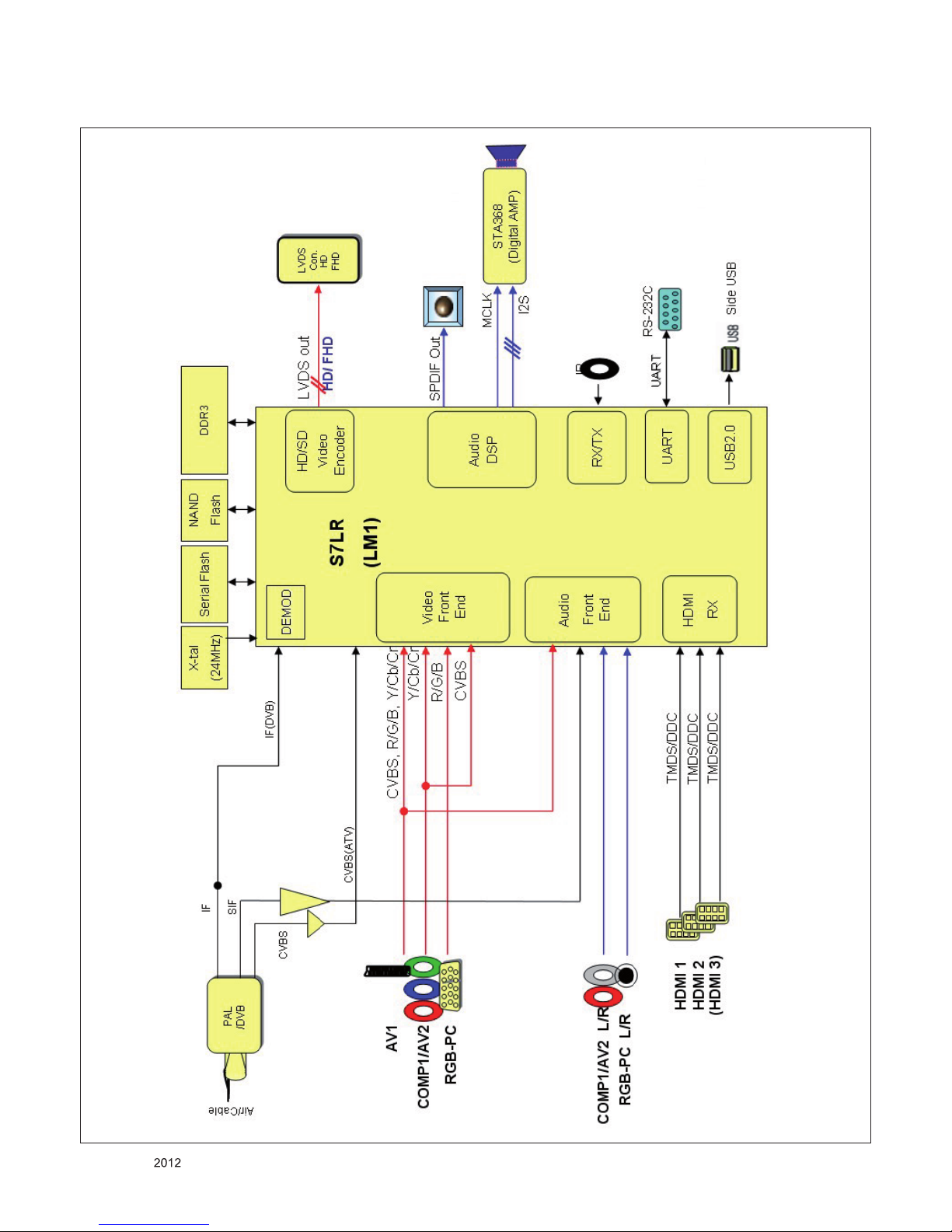
BLOCK DIAGRAM
- 14 -
LGE Internal Use OnlyCopyright © LG Electronics. Inc. All rights reserved.
Only for training and service purposes
900
910
120
501
A2
LV1
A10
A9
A12
520
601
201
204
203
304
400
590
240
202
580
205
200
206
207
302
303
310
540
300
305
301
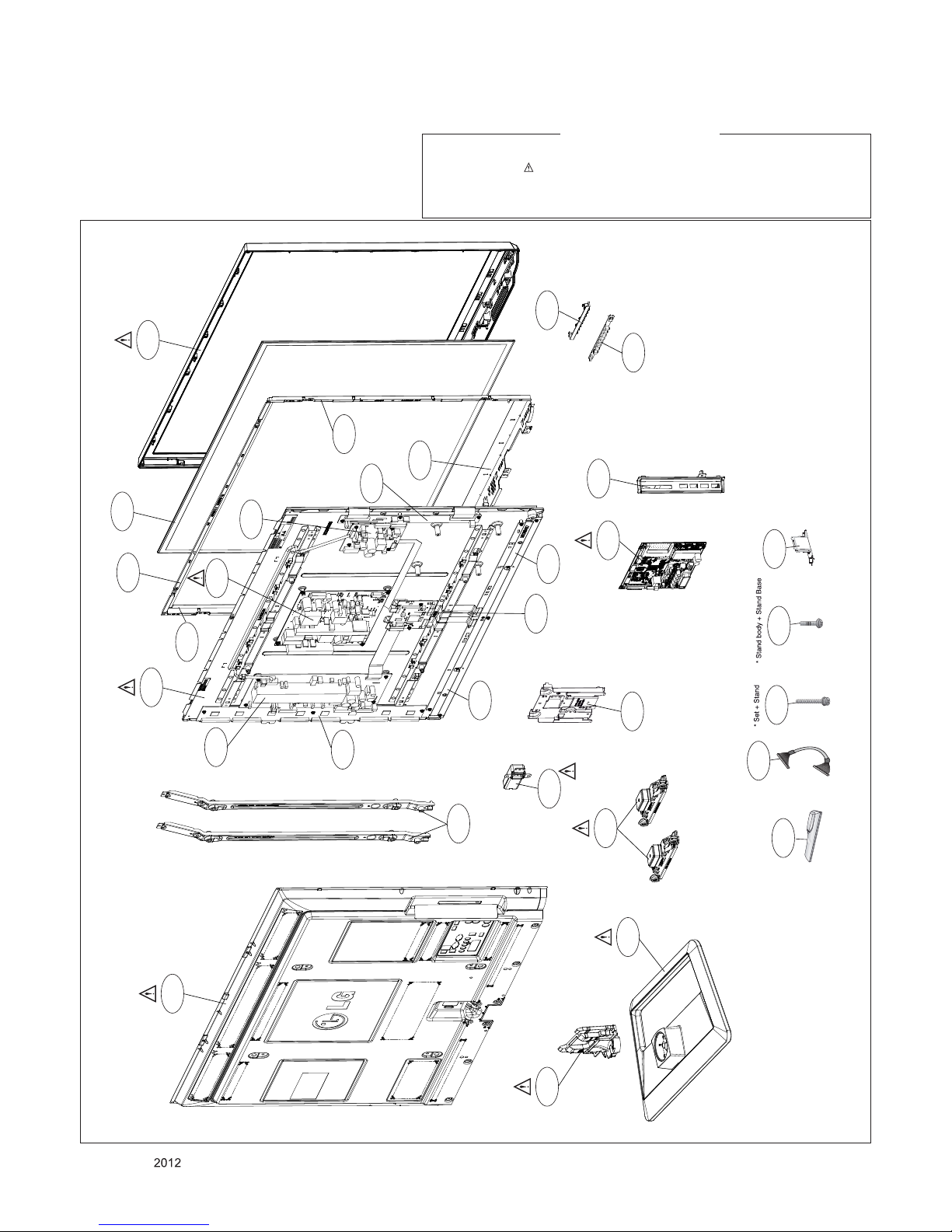
EXPLODED VIEW
Many electrical and mechanical parts in this chassis have special safety-related characteristics. These
parts are identified by in the Schematic Diagram and EXPLODED VIEW.
It is essential that these special safety parts should be replaced with the same components as
recommended in this manual to prevent X-RADIATION, Shock, Fire, or other Hazards.
Do not modify the original design without permission of manufacturer.
IMPORTANT SAFETY NOTICE
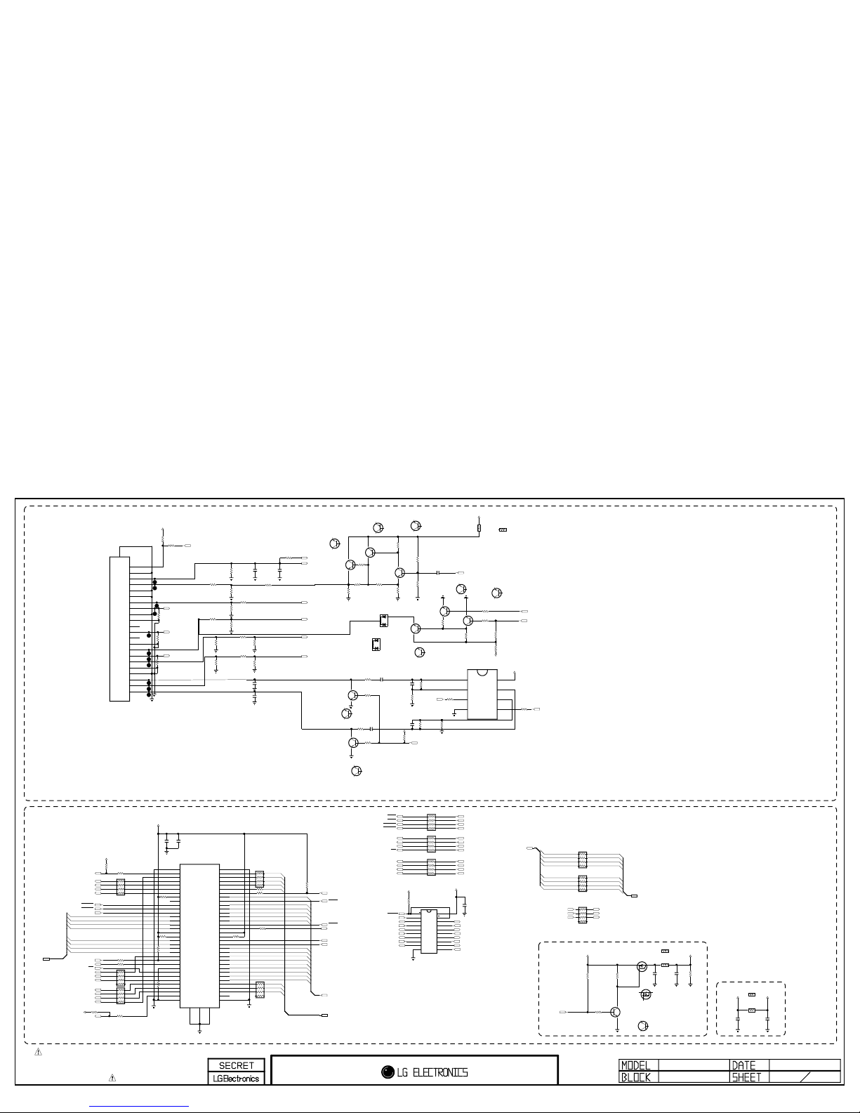
THE SYMBOL MARK OF THIS SCHEMETIC DIAGRAM INCORPORATES
SPECIAL FEATURES IMPORTANT FOR PROTECTION FROM X-RADIATION.
FILRE AND ELECTRICAL SHOCK HAZARDS, WHEN SERVICING IF IS
ESSENTIAL THAT ONLY MANUFATURES SPECFIED PARTS BE USED FOR
THE CRITICAL COMPONENTS IN THE SYMBOL MARK OF THE SCHEMETIC.
CI_ADDR[7]
CI_ADDR[0]
CI_ADDR[9]
CI_ADDR[14]
CI_ADDR[1]
CI_ADDR[10]
CI_ADDR[4]
CI_ADDR[6]
BUF2_FE_TS_DATA[0-7]
CI_ADDR[12]
CI_ADDR[3]
CI_ADDR[8]
CI_ADDR[5]
CI_ADDR[13]
CI_ADDR[2]
CI_ADDR[11]
PCM_D[0-7]
PCM_D[3]
PCM_D[4]
PCM_D[5]
PCM_D[6]
PCM_D[7]
PCM_D[0]
PCM_D[1]
PCM_D[2]
BUF2_FE_TS_DATA[0]
BUF2_FE_TS_DATA[1]
BUF2_FE_TS_DATA[2]
BUF2_FE_TS_DATA[3]
BUF2_FE_TS_DATA[4]
BUF2_FE_TS_DATA[5]
BUF2_FE_TS_DATA[6]
BUF2_FE_TS_DATA[7]
BUF1_FE_TS_DATA[0-7]
BUF2_FE_TS_DATA[2]
BUF2_FE_TS_DATA[5] BUF1_FE_TS_DATA[5]
BUF1_FE_TS_DATA[2]
BUF2_FE_TS_DATA[4]
BUF2_FE_TS_DATA[7]
BUF2_FE_TS_DATA[1]
BUF1_FE_TS_DATA[7]
BUF1_FE_TS_DATA[4]
BUF1_FE_TS_DATA[1]
BUF2_FE_TS_DATA[3]
BUF2_FE_TS_DATA[6]
BUF2_FE_TS_DATA[0]
BUF1_FE_TS_DATA[6]
BUF1_FE_TS_DATA[3]
BUF1_FE_TS_DATA[0]
+5V
R106
75
PCM_5V_CTL
C113
10uF
16V
EU
CI_ADDR[14]
R149
15K
EU
AR109
33 EU
PCM_A[5]
R137
2K
EU
+3.3V_CI
CI_ADDR[3]
Q104
MMBT3904(NXP)
EU
E
B
C
R101
33
EU
CI_IORD
/PCM_IOWR
C109
27pF
50V
EU
R110
0
READY
/PCM_IRQA
MMBT3904(NXP)
Q102
EU
PCM_A[13]
/PCM_CE
CI_IOWR
R108
75
L100
EU
120-ohm
R117
75
EU
SC1_R+/COMP1_Pr+
Q100
MMBT3904(NXP)
EU
E
B
C
PCM_A[2]
DTV/MNT_VOUT
CI_WE
R198
10K
READY
CI_OE
/PCM_REG
+3.3V_ST
AR102 33
EU
R115
470K
EU
SCART1_Lout
R109
10K
EU
R112
0
READY
CI_ADDR[1]
PCM_A[11]
CI_ADDR[2]
SC_RE2
R150
10K
EU
AR100 33
EU
/PCM_WE
SC1_B+/COMP1_Pb+
SC1_FB
CI_ADDR[6]
/PCM_WAIT
C114
27pF
50V
EU
R124
10K
EU
R157
1K
EU
IC100
TC74LCX244FT
EU
3
2Y4
2
1A1
4
1A2
1
1OE
6
1A3
5
2Y3
7
2Y2
8
1A4
9
2Y1
10
GND112A1
12
1Y4
13
2A2
14
1Y3
15
2A3
16
1Y2
17
2A4
18
1Y1
19
2OE
20
VCC
Q105
MMBT3904(NXP)
EU
E
B
C
CI_WE
AV/SC1_CVBS_IN
CI_ADDR[5]
CI_ADDR[0-14]
R113
75
EU
CI_TS_DATA[3]
R147
10K
EU
R152
6.8K
EU
BUF1_FE_TS_VAL_ERR
R153
5.6K
EU
Q114-*1
AO3407A
MULTI
G
D
S
R130 33EU
1/16W
5%
BUF2_FE_TS_DATA[0-7]
MMBT3904(NXP)
Q101
EU
CI_TS_DATA[5]
R120
2.7K
EU
R136
330
EU
CI_DET
CI_ADDR[12]
CI_IORD
SC1_G+/COMP1_Y+
R145
6.8K
EU
PCM_A[10]
R160
12K
EU
BUF2_FE_TS_CLK
R123
33
EU
CI_TS_DATA[7]
PCM_A[12]
R100
33
EU
AV/SC1_L_IN
P_17V
REG
PCM_A[9]
PCM_RST
C108
5600pF
50V
EU
R156
7.5K
EU
C137
0.1uF
16V
EU
JK102
10067972-000LF
EU
G1G2
57
21
52
16
10
47
41
5
36
59
23
45
54
18
49
43
13
7
38
2
25
56
20
51
15
9
46
40
4
35
58
22
53
17
11
48
42
12
6
37
1
24
55
19
50
44
14
8
39
3
2660
2761
2862
2963
3064
31
32
33
34
65
66
67
68
69
BUF2_FE_TS_VAL_ERR
BUF2_FE_TS_SYN
BUF2_FE_TS_SYN
+5V
CI_IOWR
R155
3K
EU
R148
15K
EU
R134
100
1/4W
EU
R132 100
EU
R143
180
EU
CI_ADDR[7]
PCM_A[6]
PCM_D[0-7]
R111
10K
EU
CI_TS_DATA[1]
/PCM_OE
R131 33EU
CI_TS_DATA[0]
PCM_A[8]
AR103
33
EU
C115
27pF
50V
EU
CI_ADDR[11]
C105
0.1uF
16V
EU
R144
470
EU
R121
10K
EU
AV/SC1_R_IN
BUF1_FE_TS_SYN
R141
220
EU
BUF2_FE_TS_VAL_ERR
+3.3V_CI
CI_TS_VAL
/CI_CD1
AR104
33
EU
R159
12K
EU
L103
EU
120-ohm
BUF2_FE_TS_DATA[0-7]
AR108
33 EU
C136
0.1uF
16V
READY
Q113
MMBT3904(NXP)
EU
E
B
C
+3.3V
R135
0
EU
IC101
AZ4580MTR-E1
3
IN1+
2
IN1-
4
VEE
1
OUT1
5
IN2+
6
IN2-
7
OUT2
8
VCC
Q107
MMBT3904(NXP)
EU
E
B
C
R102
100
EU
/CI_CD2
L101
EU
120-ohm
CI_TS_DATA[2]
AV/SC1_DET
SCART1_Rout
R184
10K
READY
R181
10K
EU
R187
10K
EU
1/16W
5%
R104
10K
EU
/PCM_IORD
CI_ADDR[13]
SC1_ID
C107
5600pF
50V
EU
AR101 33
EU
C116
10uF
16V
EU
CI_TS_SYNC
CI_ADDR[8]
C104
0.1uF
16V
EU
R118
470K
EU
1/16W
5%
SC1_SOG_IN
JK100
PSC008-02
EU
1
AUDIO_R_OUT
2
AUDIO_R_IN
3
AUDIO_L_OUT
4
AUDIO_GND
5
B_GND
6
AUDIO_L_IN
7
B_OUT
8
ID
9
G_GND
10
D2B_IN
11
G_OUT
12
D2B_OUT
13
R_GND
14
RGB_GND
15
R_OUT
16
RGB_IO
17
SYNC_GND1
18
SYNC_GND2
19
SYNC_OUT
20
SYNC_IN
21
COM_GND
23
SHIELD
22
AV_DET
P_17V
R114
10K
EU
R139
2K
EU
SC_RE1
+3.3V_CI
CI_TS_DATA[4]
C112
10uF
16V
EU
R158
1K
EU
Q106
MMBT3904(NXP)
EU
E
B
C
R165
10K
EU
0
R129
EU
PCM_A[4]
R103
100
EU
R127
12K
EU
BUF2_FE_TS_CLK
+3.3V
R116
470K
EU
R107
75
PCM_A[0]
BUF1_FE_TS_DATA[0-7]
+5V
AR106 33
EU
CI_ADDR[9]
R126
12K
EU
PCM_A[7]
C131
0.1uF
16V
READY
PCM_A[14]
REG
R146
18K
EU
C100
22uF
10V
EU
CI_TS_DATA[6]
R189
10K
EU
R151
10K
EU
CI_OE
SCART1_MUTE
R140
2K
EU
C101
0.1uF
16V
EU
R154
5.6K
EU
R105
1K
EU
CI_ADDR[0]
+5V
BUF1_FE_TS_CLK
PCM_A[3]
R138
2K
EU
CI_TS_CLK
R119
75
EU
AR107 33
EU
CI_ADDR[4]
R128 0
READY
+5V_CI_ON
AR105
33
EU
PCM_A[1]
AR110
33
EU
+5V_CI_ON
CI_ADDR[10]
R133
10K
EU
C111
220pF
50V
EU
L103-*1
CB1608UA121T
DUP_DVB
L101-*1
CB1608UA121T
DUP_DVB
L100-*1
CB1608UA121T
DUP_DVB
Q104*-1
2SC3052
DUP_DVB
E
B
C
Q113*-1
2SC3052
DUP_DVB
E
B
C
Q107-*1
2SC3052
DUP_DVB
E
B
C
Q106-*1
2SC3052
DUP_DVB
E
B
C
Q102-*1
2SC3052
DUP_DVB
E
B
C
Q100-*1
2SC3052
DUP_DVB
E
B
C
Q101-*1
2SC3052
DUP_DVB
E
B
C
Q105-*1
2SC3052
DUP_DVB
E
B
C
Q114
ZXMP3F30FHTA
EU
G
D
S
Q103
MMBT3906(NXP)
EU
E
B
C
Q103-*1
ISA1530AC1
DUP_DVB
E
B
C
D112
MMBD6100
EU
A2
C
A1
D112-*1
KDS184
DUP_DVB
A2
C
A1
C106
0EU
SCART,CI Slot
GP4_S7LR3
1
DTV_R_OUT
SC1_VOUT
REC_8
CI POWER ENABLE CONTROL
CI SLOT
Full SCART
3.3V_CI
2011-12-01
PDP GP4 S7LR3
EAX64696601
7
Copyright © 2012 LG Electronics Inc. All rights reserved.
Only for training and service purposes
LGE Internal Use Only
 Loading...