

Page 1

EDBPM-H515
.$b(
Ä.$b(ä
Betriebsanleitung
Operating Instructions
Instructions de mise en service
HMI
EPM-H515
Bedieneinheit
Operating unit
Unitédecommande
Page 2

Page 3
3
2
3
1
4
2
INPUT VOLTAGE:18-32 VDC 15 W
FUSE 1.25 A
3
1
4
2
+-
N.C.
24VDC
LPT
1
MSP
V-
Shield
CAN-
12345
CAN+
N.C.
0
h515_002
Page 4

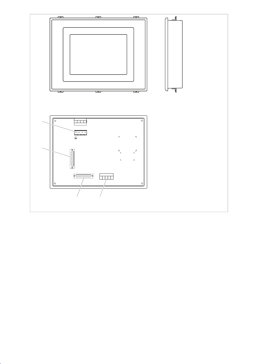
Pos. Beschreibung Funktion
Klemmenleistee 5-polig Systembus (CAN)
DB25 Buchse Serieller Port für PC oder SPS (MSP)
DB25 Buchse Paralleler Port für Drucker (LPT)
Klemmenleiste 4-polig DC-Spannungsversorgung 24 V
4
EDBPM-H515 DE/EN/FR 2.0
Page 5

Diese Dokumentation ist gültig für die Bedieneinheit EPM-H515 ab dem Gerätestand
Type EPM - H515 1A 10
Produktreihe
EPM Bedieneinheit
Hardwarestand
Softwarestand
Was ist neu?
Stand ID-Nr. Änderungen
1.0 01/2005 TD 23 13036507 Feldtest
2.0 06/2005 TD 23 13036507 Serienstand
© 2005 Lenze Drive Systems GmbH, Hans-Lenze-Straße 1, D-31855 Aerzen
Ohne besondere schriftliche Genehmigung von Lenze Drive Systems GmbH darf kein Teil dieser Dokumentation vervielfältigt oder Dritten zugänglich gemacht werden.
Wir haben alle Angaben in dieser Dokumentation mit größter Sorgfalt zusammengestellt und auf Übereinstimmung
mit der beschriebenen Hard- und Software geprüft. Trotzdem können wir Abweichungen nicht ganz ausschließen. Wir
übernehmen keine juristische Verantwortung oder Haftung für Schäden, die dadurch eventuell entstehen. Notwendige Korrekturen werden wir in die nachfolgenden Auflagen einarbeiten.
EDBPM-H515 DE/EN/FR 2.0
5
Page 6

Inhalti
1 Vorwort und Allgemeines 8...........................................
1.1 Über diese Betriebsanleitung 8..................................
1.2 Verwendete Begriffe 8.........................................
1.3 Lieferumfang 8...............................................
1.4 Gestaltung der Sicherheitshinweise 9.............................
2 Technische Daten 10..................................................
2.1 Allgemeine Daten / Einsatzbedingungen 10........................
2.2 Elektrische Daten 11............................................
2.2.1 Eigenschaften der Bedieneinheit 12......................
2.2.2 Schnittstellenbeschreibung 16..........................
2.3 Abmessungen 17...............................................
2.4 Einbauausschnitt 17............................................
3 Mechanische Installation 18............................................
3.1 Bedieneinheit befestigen 18.....................................
4 Elektrische Installation 19..............................................
4.1 Belegung der Anschlussklemmen 19...............................
4.2 Systembus (CAN) verdrahten 20..................................
4.3 Memory Card einbauen 21.......................................
4.3.1 Memory Card 8 MB (Backup) 21.........................
5 Inbetriebnahme 23...................................................
5.1 Erstes Einschalten 23...........................................
5.2 Projekt in die Bedieneinheit übertragen 24.........................
5.2.1 Bedieneinheit und PC verbinden 24......................
5.2.2 Projekt-Download 25..................................
5.2.3 Verbindung zum PC entfernen 26........................
5.3 Statusmeldungen der Bedieneinheit 27............................
5.4 Datum/Uhrzeit und Kontrast einstellen 28.........................
6 Bedienung 30........................................................
6.1 Tastenfunktionen 30............................................
6.2 Daten eingeben 31.............................................
6.3 Informationsmeldung aufrufen 36................................
6.4 Alarmmeldungen aufrufen 37....................................
6.5 Hilfe aufrufen 39...............................................
6.6 Daten sichern auf 8 MB Memory Card 40...........................
6
EDBPM-H515 DE/EN/FR 2.0
Page 7

Inhalt i
7 Fehlersuche und Störungsbeseitigung 42.................................
7.1 Störungsmeldungen 42.........................................
8Wartung 43.........................................................
9 Anhang 44..........................................................
9.1 Chemikalienbeständigkeit 44....................................
9.2 Stichwortverzeichnis 46.........................................
EDBPM-H515 DE/EN/FR 2.0
7
Page 8

1
Bedeeet55
ÜbepüeSeacatdeeeugsoot,obde
6Schraub
e
3
5
t
immt.F
ü
h
trägl
ichrek
lamierteM
ä
lüb
6SchraubenM4×35mm
nimmtLenzekeineGewährleistung
1Dichtung
er.
p
rer
1Klemmleiste5po
l.fürAnschlussSyste
m
erkennbareMängel/Unvollständigkeitsofortbeide
r
Vorwort und Allgemeines
Über diese Betriebsanleitung
1 Vorwort und Allgemeines
Mit der Bedieneinheit EPM-H515 können Sie auf Codestellen von Lenze Antriebsreglernzugreifen und d iese aufkomfortable Weise steuern. Die Kommunikation erfolgt über Systembus (CAN).
Mit der Lenze-Software »HMI Designer« lässt sich die Programmierung der Bedieneinheit einfach realisieren.
1.1 Über diese Betriebsanleitung
ƒ
Die vorliegende Betriebsanleitung dient dem sicheren und fehlerfreien
Arbeiten an und mit der Bedieneinheit EPM-H515.
ƒ
Alle Personen, die an und mit der Bedieneinheit EPM-H515 arbeiten, müssen
bei ihren Arbeiten die Betriebsanleitungen verfügbar haben und die für sie
relevanten Angaben und Hinweise beachten.
ƒ
Die Betriebsanleitung muss stets komplett und in einwandfrei lesbarem
Zustand sein.
1.2 Verwendete Begriffe
Begriff Im folgenden Text verwendet für
Antriebsregler Lenze Frequenzumrichter 8200 vector und 9300 vector,
HMI Human Machine Interface
Lenze Servo-Umrichter 9300 und 9400
1.3 Lieferumfang
Menge Wichtig
1 Bedieneinheit EPM-H515 Überprüfen Sie nach Erhalt derLieferung sofort, ob der
1 Betriebsanleitung
6Befestigungsschellen
1 Dichtung
1 Klemmleiste 4 pol. fürAnschluss DC-Spannungsversorgung
1 Klemmleiste 5
bus (CAN)
nM4×
mm
ol.für Anschluss System-
8
Lieferumfang mit den Warenbegleitpapieren übereins
nimmt Lenze keine Gewährleistung.
Reklamieren Sie
-
rnac
erkennbare Transportschädensofortbeim Anliefer
.
erkennbare Mängel/Unvollständigkeit sofort bei der
zuständigen Lenze-Vertretung.
EDBPM-H515 DE/EN/FR 2.0
-
nge
.
er-
Page 9

1.4 Gestaltung der Sicherheitshinweise
Um aufGefahrenundwichtige Informationenhinzuweisen, werdenin dieser Dokumentation folgende Signalwörter und Symbole verwendet:
Sicherheitshinweise
Aufbau der Sicherheitshinweise:
Gefahr!
(kennzeichnet die Art und die Schwere der Gefahr)
Hinweistext
(beschreibt die Gefahr und gibt Hinweise, wie sie vermieden werden
kann)
Piktogramm und Signalwort Bedeutung
Gefahr!
Gefahr!
Stop!
Anwendungshinweise
Vorwort und Allgemeines
Gestaltung der Sicherheitshinweise
Gefahr von Personenschäden durch gefährliche el ektrische Spannung
Hinweis auf eine unmittelbar drohende Gefahr, die den
Tod oder schwere Verletzungen zur Folge haben kann,
wenn nicht die entsprechendenMaßnahmengetroffen
werden.
Gefahr von Personenschäden durch eine allgemeine Gefahrenquelle
Hinweis auf eine unmittelbar drohende Gefahr, die den
Tod oder schwere Verletzungen zur Folge haben kann,
wenn nicht die entsprechendenMaßnahmengetroffen
werden.
Gefahr von Sachschäden
Hinweis auf eine mögliche Gefahr,die Sachschäden zur
Folge haben kann, wenn nicht die entsprechendenMaßnahmen getroffen werden.
1
Piktogramm und Signalwort Bedeutung
X
H
EDBPM-H515 DE/EN/FR 2.0
Hinweis!
Tipp!
Wichtiger Hinweis für die störungsfreie Funktion
Nützlicher Tipp für die einfache Handhabung
Verweis auf andere Dokumentation
9
Page 10

2
Technische Daten
Allgemeine Daten / Einsatzbedingungen
2 Technische Daten
2.1 Allgemeine Daten / Einsatzbedingungen
Bereich Werte
Konformität CE EMV-Richtlinie (89/336/EEC)
Approbation
Angewandte Normen zu
Grenzwerten
Schutzart
Klimatische Bedingungen
Zulässige Temperatur-
bereiche
Transport -20 °C ... +60 °C
Lagerung -20 °C ... +60 °C
Betrieb 0 °C ... +50 °C
Masse 1,5 kg
cULus: in Vorbereitung
Störaussendung nach EN 50081-2 (1994)
Störfestigkeit nach EN 50082-2 (1995)
IP65 (Frontseite)
Feuchte (ohne Betauung) <85 %
10
EDBPM-H515 DE/EN/FR 2.0
Page 11

2.2 Elektrische Daten
Display
etsce
ete
Spece
Scttste
e
Bereich Werte
Display Typ
Touch screen Matrix40×30(je16×16Pixel)
Auflösung 640 × 480 Pixel
Sichtbare Größe 158 × 118 mm
Zeilen
Zeichengröße
Fonts Programmierbare fonts, Windows fonts
Kontrasteinstellung Automatischer Temperaturausgleich
Hintergrundbeleuchtung
Uhr Hardwareuhr Speicherung über Kondensator,
Elektrischer Anschluss
Netzwerk
Speicher Anwenderprogramm (Text + Grafik)
Schnittstellen
DC-Spannungsversorgung DC 24 V (+18 ... 32 V)
Leistungsaufnahme
Protokoll Systembus (CAN)
Kommunikationsmedium DIN ISO 11898
Netzwerk-Topologie Linie (beidseitig abgeschlossen mit
Datenspeicher (Flash EPROM) 128kB
Speicher für Windows fonts 512 kB
Memory Card (Back up) 8MB
seriell MSP (DB25 Buchse) RS232
parallel LPT Centronics
Technische Daten
Elektrische Daten
LCD 256 Farben STN
einfache Zeichengröße 30 Zeilen à 80 Zeichen
zweifache Zeichengröße 15 Zeilen à 40 Zeichen
vierfache Zeichengröße 7 Zeilen à 20 Zeichen
einfache Zeichengröße 1,89×3,79mm,Text:8×16Pixel
zweifache Zeichengröße 3,79×7,58mm,Text:16×32Pixel
vierfache Zeichengröße 7,58 × 15,16 mm, Text: 32 × 64 Pixel
Min. Lebensdauer bei 25°C
CCFL-Röhre
15000 h
min. 72 h, typ. 130 h
15 W bei DC 24 V
120 Ω)
960 kB + 6MB
2
EDBPM-H515 DE/EN/FR 2.0
11
Page 12

2
Alarm
DirektbefehlmitWertStruktur
Technische Daten
Elektrische Daten
Eigenschaften der Bedieneinheit
2.2.1 Eigenschaften der Bedieneinheit
Die Bedieneinheit unterstützt die in der Tabelle aufgeführten Eigenschaften.
Beschreibung Wert
Alarm
Backup/Wiederherstellen
Beschriftung
Der Rezeptstruktur zugeordnete System-Variablen
Direktbefehl mit Wert-Struktur
Drucken
Dynamische Funktionen
Einfügen von Bildern
Feld
Puffer 256
Alarmmeldungen (insgesamt/gleichzeitig ak-
tiv)
Hilfe zu Alarmmeldungen 1024
Wert subtrahieren
Wert addieren
Wert ODER verknüpfen
Wert UND verknüpfen
Wert XOR verknüpfen
Wert setzen
Druckseiten (insgesamt/Anzahl der Felder pro
Seite)
Kopf-, Fußzeile (insgesamt/Anzahl der Felder
pro Kopf-, Fußzeile)
Reports 128
Bilderlisten (mit Bit-Gruppen, Einzel-Bits oder
Zahlenwerten)
Textlisten (mit Bit-Gruppen, Einzel-Bits oder
Zahlenwerten)
Bewegliches symbolisches Feld
1024/256
1024/128
128/128
1)
1024
12
EDBPM-H515 DE/EN/FR 2.0
Page 13

Funktionen
Funktione
n
Gasceutoe
Grafische Funktionen
Technische Daten
Elektrische Daten
Eigenschaften der Bedieneinheit
Anzeigen der Seiten-Hilfe
Anzeige der Statusseite des Treibers
Bit permanent setzen
Bit permanent zurücksetzen
Bit umkehren
Direktbefehl mit Wert-Struktur
Echtzeitbit setzen
Echtzeitbit zurücksetzen
Gehe zu Seite
Interner Befehl
Lesen der automatisch abgetasteten Trends
neu starten
Lesen der automatisch abgetasteten Trends
stoppen
Makro
Bogen
Kreis
Linie
Rechteck
Balkengrafik
2
WertBeschreibung
EDBPM-H515 DE/EN/FR 2.0
13
Page 14

2
InterneBefehl
e
o
g
Technische Daten
Elektrische Daten
Eigenschaften der Bedieneinheit
WertBeschreibung
Interne Befehle
Interne Register 4096 Byte
Logik
Meldungen
Alarmregister anzeigen
Alarmregister drucken
Alarm und Trendpuffer im Speicher sichern
Bedienseite
Blattvorschub auf dem Drucker
Die generelle Seitenzahl auf Null setzen
Hardcpoy
Hilfe der Seite
Nächste Seite
Passwort ändern
Passwort Login
Passwort Logout
Projekt beenden
Projektinformationen anzeigen
Reports
Rezept an das Gerät senden
Rezept aus Datenspeicher laden
Rezept im Datenspeicher sichern
Rezept löschen
Rezept vom Videopuffer an das Gerät senden
Rezept-Verzeichnis anzeigen
Seiten-Verzeichnis anzeigen
Sprache ändern
Trendpuffer leeren
Vom Gerät empfangenes Rezept im Datenspei-
cher sichern
Vom Gerät empfangenes Rezept im Puffer sichern
Vorangehende Seite
Automatische Operationen 32
Gleichungen 32
Timer 32
Makros (insgesamt/Befehlepro Makro) 1024/16
Informationsmeldungen (insgesamt/gleichzei-
tig aktiv)
Hilfe zu Meldungen 1024
Systemmeldungen
Meldungsfeld
1024/256
14
EDBPM-H515 DE/EN/FR 2.0
Page 15

Technische Daten
Objekte
Passwor
t
Seite
n
Sprache
n
oucbuttosudtoucaeas
eds
/
Uet/Dat
u
aab
e
56poSet
e
Elektrische Daten
Eigenschaften der Bedieneinheit
WertBeschreibung
Objekte
Passwort
Rezepte (Anzahl/Variablen pro Rezept) 1024/512
Seiten
Sprachen
Statische Bitmaps
Textlisten
Touch buttons und touch areas
Trends
Uhrzeit/Datum
Variablen
1)
von der Projektgröße begrenzter Richtwert
2)
abhängig vom verfügbarem Speicher
Drehschalter
Drehpotentiometer 128
Indikator 128
Schiebepotentiometer 128
Schiebeschalter 128
Zeichen 8Bit
Ebenen 10
Seiten 1024
Hilfe zu Seiten 1024
Unterstützte Sprachen 8
Frei wählbare fonts
Touch buttons 1200 pro Seite
Touch areas 256
(Anzahl pro Seite/Kanäle pro Trend) 8/8
Puffer 128
Automatisch abgetastet (Speicher/Trends/Er-
fassung)
Auf Befehl abgetastet (Speicher/Trends/Erfassung)
Uhrzeit mit Sekunden
Uhrzeit ohne Sekunden
Darstellung als Wochentag
Darstellung als Datum (tt.mm.jjjj)
Grenzwerte- und lineare Korrektur-Variablen
Bewegungsvariablen (bewegliches symboli-
sches Feld)
Schwellenvariablen
Numerische Gleitpunkt-Variablen
Numerische Variablen (DEC, HEX, BIN, BCD)
String-Variablen (ASCII)
128
6144 Byte /
/480
256 pro Seiten
2
2)
EDBPM-H515 DE/EN/FR 2.0
15
Page 16

2
Technische Daten
Elektrische Daten
Schnittstellenbeschreibung
2.2.2 Schnittstellenbeschreibung
MSP LPT
14
14
1
h410_013 h410_013
Abb. 2-1 DB25 Buchse
Pin Signal Pin Signal
1n.c. 1 Strobe
2 Tx RS232 OUT 2 PRN Data 0
3 Rx RS232 IN 3 PRN Data 1
4 RTS RS232 OUT 4 PRN Data 2
5 CTS RS232 IN 5 PRN Data 3
6 n. c. 6 PRN Data 4
7 Signal GND 7 PRN Data 5
8 n. c. 8 PRN Data 6
9 ... 16 Signale werden nicht ausgewertet 9 PRN Data 7
17 n. c. 10 n. c.
18 Signal wird nicht ausgewertet 11 PRN Busy
19 ... 21 n. c. 12 ... 17 n. c.
22 ... 25 Signale werden nicht ausgewertet 18 ... 25 Signal GND
n.c. Nicht angeschlossen
1
16
EDBPM-H515 DE/EN/FR 2.0
Page 17

2.3 Abmessungen
Technische Daten
Abmessungen
2
a
d1 d1d2 d2 e1
Abb. 2-2 Abmessungen
a [mm] b [mm] d1 [mm] d2 [mm] e [mm] e1 [mm]
188,6 245,9 27,1 95,8 43,6 37,6
2.4 Einbauausschnitt
b
b
e
h515_003
a
Abb. 2-3 Einbauausschnitt
EDBPM-H515 DE/EN/FR 2.0
a [mm] b [mm]
176 233
h515_004
17
Page 18

3
Mechanische Installation
Bedieneinheit befestigen
3 Mechanische Installation
3.1 Bedieneinheit befestigen
Die Maße für denEinbauausschnitt entnehmen Sie dentechnischenDaten. (Q 17)
1. Bedieneinheit mit Dichtung in den Einbauausschnitt schieben.
2. Befestigungsschellen in die Öffnungsschlitze der Bedieneinheit schieben.
3. Schrauben gegen die Einbautafel drehen
und festziehen.
1
0
H515_005
2
InputVoltage 18-32 VDC 15 W
FUSE1,25 A
1
2
3
N.C.
4
CAN+
Shield
5
CAN-
4
V-
3
2
1
2
h515_006
3
18
W
5
1
C
D
V
2
-3
18
ge
a
lt
A
o
5
V
,2
ut
1
p
E
In
S
U
F
1
2
3
N.C.
4
CAN+
Shield
5
CAN-
4
V-
3
2
1
3
EDBPM-H515 DE/EN/FR 2.0
h515_007
Page 19
4 Elektrische Installation
4.1 Belegung der Anschlussklemmen
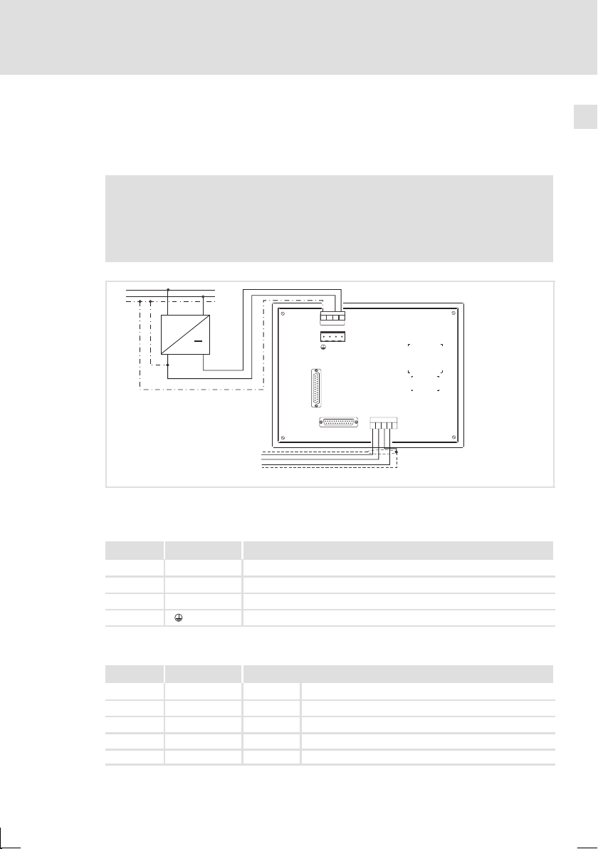
Stop!
ƒ
Beschädigung angeschlossener Geräte. Verbinden Sie den PE-Leiter
so wie es in der Abbildung dargestellt ist!
ƒ
Bedieneinheit nur im spannungslosen Zustand verdrahten!
L1
N
PE
~
+18…32VDC
Elektrische Installation
Belegung der Anschlussklemmen
3
1
4
2
INPUTVOLTAGE: 18-32 VDC 15W
FUSE 1.25A
3
1
4
2
+-
N.C.
24VDC
LPT
MSP
V-
CAN+
Shield
CAN-
N.C.
12345
4
Abb. 4-1 Belegung der Anschlussklemmen
DC-Spannungsversorgung
Klemme Bezeichnung Erläuterung
1 DC +24 V Versorgungsspannung (DC +18 V ... 32 V)
2 DC 0 V GND Versorgungsspannung, Bezugspotential
3 n. c. Nicht angeschlossen
4 PE-Potential
Systembus (CAN)
Klemme Bezeichnung Erläuterung
1V- GND Bezugspotential
2 CAN- LO Systembus LOW (Datenleitung)
3 Shield Schirm des Systembus-Kabels auflegen
4 CAN+ HI Systembus HIGH (Datenleitung)
5 n. c. Nicht angeschlossen
EDBPM-H515 DE/EN/FR 2.0
CAN-GND
CAN-LO
CAN-HI
h515_008
19
Page 20

4
Elektrische Installation
Systembus (CAN) verdrahten
4.2 Systembus (CAN) verdrahten
Hinweis!
ƒ
Verbinden Sie nur Klemmen gleichen Signaltyps miteinander.
ƒ
Weitere Informationen zum Systembus (CAN) finden Sie im
Kommunikationshandbuch CAN.
A
(H515)
1
ShieldCAN--V CAN+ N.C.
120
Abb. 4-2 Verdrahtung des Systembus (CAN)
Busteilnehmer 1 A2Busteilnehmer 2 AnBusteilnehmer n
A
1
CG LO HI
A
2
CG LO HI
A
n
CG LO HI CG LO
HI
120
h515_009
Bitte folgen Sie bei der Verwendung des Signalkabels unseren Empfehlungen:
Spezifikation des Übertragungskabels
Gesamtlänge ≤ 300 m
Kabeltyp LIYCY2x2x0,5mm
(paarverseilt mit Abschirmung)
Leitungswiderstand ≤ 80 Ω/km ≤ 80 Ω/km
Kapazitätsbelag ≤ 130 nF/km ≤ 60 nF/km
2
≤ 1000 m
CYPIMF2x2x0,5mm
(paarverseilt mit Abschirmung)
2
20
EDBPM-H515 DE/EN/FR 2.0
Page 21
4.3 Memory Card einbauen
Stop!
ƒ
Schalten Sie vor Arbeitsbeginn die Bedieneinheit spannungsfrei, um
Beschädigungen an elektrischen Bauelementen zu vermeiden.
ƒ
Die Bedieneinheit und die Memory Cards enthalten elektrostatisch
gefährdete Bauelemente, die Sie durch unsachgemäße Handhabung
leicht beschädigen können.
4.3.1 Memory Card 8 MB (Backup)
ƒ
Auf diesen Speicherbaustein können Sie Ihr anwendungsspezifisch
konfiguriertes Projekt sichern und archivieren.
ƒ
Sie können den Speicherbaustein mit dem gesicherten Projekt in eine
Bedieneinheit gleichen Typs einbauen, um das Projekt in diese Bedieneinheit
zu übertragen.
ƒ
Die 8 MB Memory Card ist bei Lenze erhältlich unter der Best.-Nr. EPZ-H221.
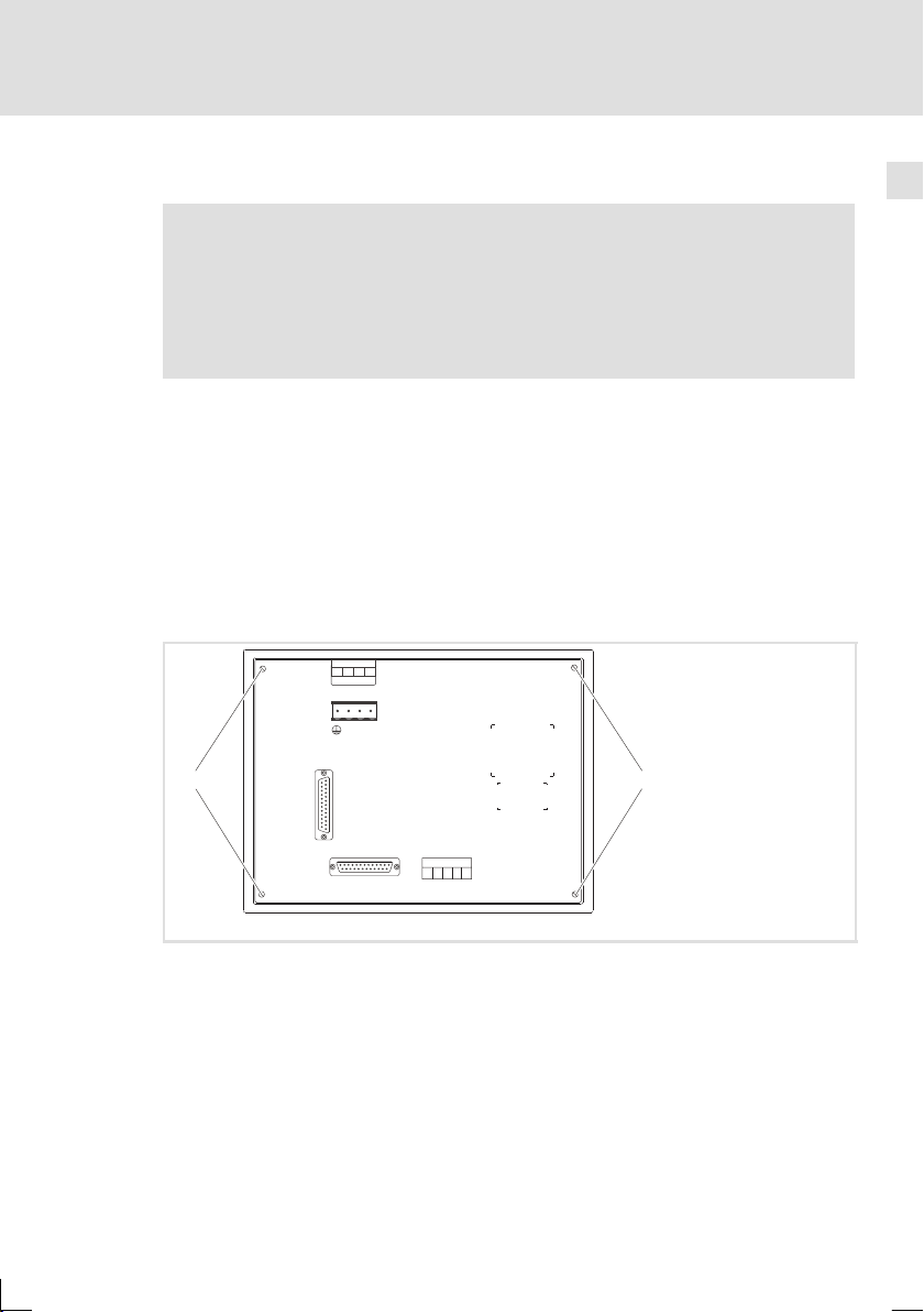
Gehäusedeckel abnehmen
3
1
4
2
INPUT VOLTAGE:18-32 VDC 15 W
FUSE 1.25 A
3
1
4
2
+-
N.C.
24VDC
LPT
0 0
Elektrische Installation
Memory Card einbauen
Memory Card 8 MB (Backup)
4
Abb. 4-3 Gehäusedeckel abnehmen
1. Schrauben lösen und Gehäusedeckel abnehmen.
EDBPM-H515 DE/EN/FR 2.0
MSP
V-
CAN+
Shield
CAN-
N.C.
12345
h515_011
21
Page 22
4
Elektrische Installation
Memory Card einbauen
Memory Card 8 MB (Backup)
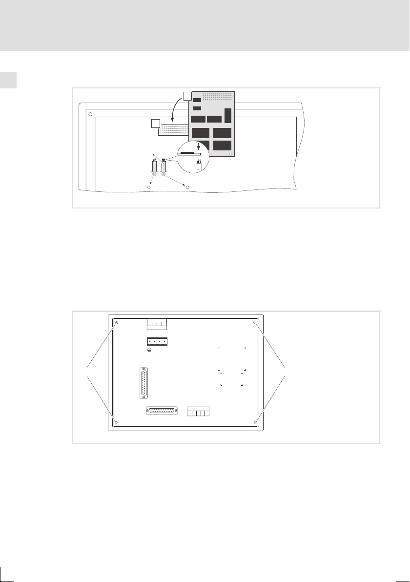
Memory Card 8 MB (Backup) einbauen
0
1
2
h515_012
Abb. 4-4 Memory Card 8 MB (Back up) einbauen
1. Abstandsstifte in die Bohrungen der Hauptplatine einsetzen und einrasten
lassen.
2. Memory Card mit der Stiftl eiste i n die Buchsenleiste einsetzen und
vorsichtig andrücken.
3. Bohrungen der Memory Card zu den Abstandsstiften ausrichten.
4. Memory Card auf die Abstandsstifte drücken und einrasten lassen.
Gehäusedeckel schließen
22
3
1
4
2
INPUT VOLTAGE:18-32 VDC 15 W
FUSE 1.25 A
3
1
4
2
+-
N.C.
24VDC
LPT
0 0
MSP
Abb. 4-5 Gehäusedeckel schließen
1. Gehäusedeckel aufsetzen, Schrauben eindrehen und festziehen.
V-
CAN+
Shield
CAN-
N.C.
12345
EDBPM-H515 DE/EN/FR 2.0
h515_011
Page 23

5 Inbetriebnahme
5.1 Erstes Einschalten
Für die Inbetriebnahme ist eine vollständige Verdrahtung des S ystembus notwendig.
Überprüfen Sie vor dem Einschalten der Versorgungsspannung ...
ƒ
die gesamte Verdrahtung auf Vollständigkeit und Kurzschluss,
ƒ
ob das Bussystem beim physikalisch ersten und letzten Busteilnehmer
abgeschlossen ist.
Inbetriebnahme
Erstes Einschalten
5
EDBPM-H515 DE/EN/FR 2.0
23
Page 24
5
Inbetriebnahme
Projekt in die Bedieneinheit übertragen
Bedieneinheit und PC verbinden
5.2 Projekt in di e Bedieneinheit übertragen
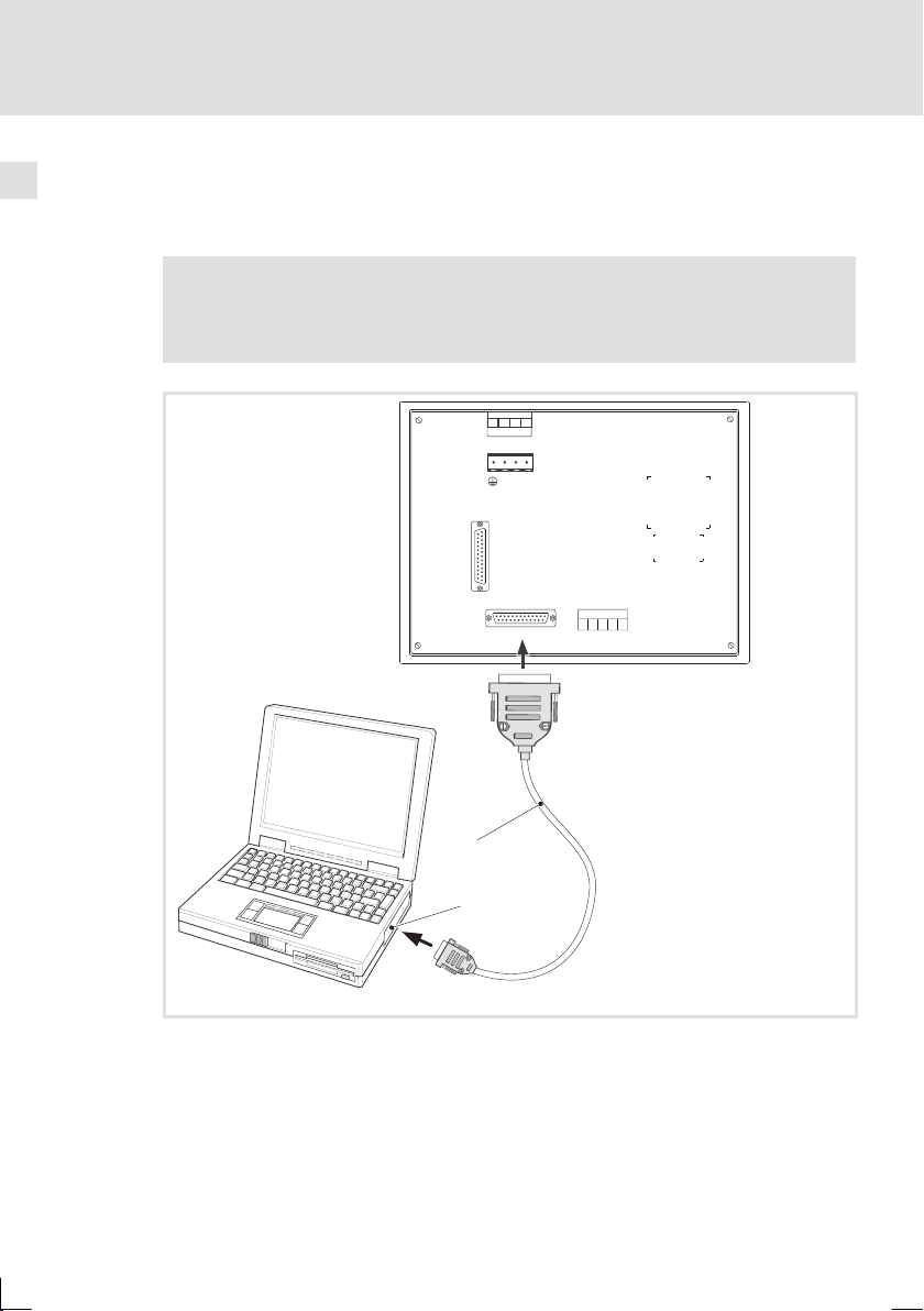
5.2.1 Bedieneinheit und PC verbinden
Stop!
Die Verbindung zwischen PC und Bedieneinheit nur bei ausgeschalteten
Geräten herstellen!
LPT
3
1
4
2
3
1
4
2
+-
N.C.
24VDC
INPUT VOLTAGE:18-32 VDC 15 W
FUSE 1.25A
l
HMI Designer
MSP
V-
Shield
CAN-
12345
CAN+
N.C.
0
1
Abb. 5-1 Bedieneinheit und PC verbinden
ƒ
Downloadkabel EPZ-H110 an der Bedieneinheit auf MSP-Schnittstelle und
am PC auf COM1 oder COMx stecken.
h515_010
24
EDBPM-H515 DE/EN/FR 2.0
Page 25

5.2.2 Projekt-Download
Hinweis!
Im »HMI Designer« können Sie auswählen, ob mit dem Laden des
Projekts gleichzeitig die Firmware aktualisiert werden soll.
Die Firmware muss immer beim ersten Download eines Projekts in die
Bedieneinheit bzw. nach einem Update des Projektierungstool
»HMI Designer« aktualisiert werden.
X
Tipp!
Beispiel-Projekte für die Bedieneinheit finden Sie im Projektierungstool
»HMI Designer« unter Datei Öffnen... Samples.
Inbetriebnahme
Projekt in die Bedieneinheit übertragen
Projekt-Download
5
EDBPM-H515 DE/EN/FR 2.0
25
Page 26
5
Inbetriebnahme
Projekt in die Bedieneinheit übertragen
Verbindung zum PC entfernen
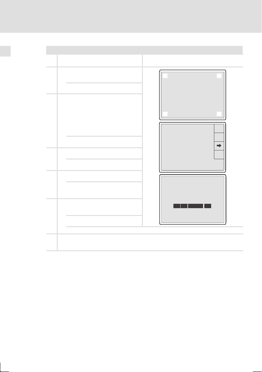
Das müssen Sie tun
PC einschalten und Projektierungstool
A
»HMI Designer« starten.
B Versorgungsspannungfür Bedieneinheit
einschalten.
Das Gerät wird initialisiert.
C Nachder InitialisierungSystemseite an-
wählen. Dazu das Display in den Ecken
oben rechts und unten links oder
oben links und unten rechts berüh-
ren.
Die erste zu berührende Ecke darf kein anwählbares Feld enthalten.
Die Systemseite erscheint.
D Das Feld ”TRAN PAGE” berühren.
DieTransferPageerscheint.
E Das Feld MSP berühren.
Die Bedieneinheit ist bereitfür den
Datenempfangvom PC.
F Gewünschtes Projekt vom »HMI Designer«
in die Bedieneinheitübertragen.
2
2
2
2
2
2
2
2
2
2
1
1
1
1
1
1
1
1
1
1
Port : NET
Port : NET
Port : NET
Port : NET
Port : NET
Port : NET
Port : NET
Port : NET
Port : NET
Port : NET
Driver : CAN Lenze M
Driver : CAN Lenze M
Driver : CAN Lenze M
Driver : CAN Lenze M
Driver : CAN Lenze M
Driver : CAN Lenze M
Driver : CAN Lenze M
Driver : CAN Lenze M
Driver : CAN Lenze M
Driver : CAN Lenze M
Ver : 1.12
Ver : 1.12
Ver : 1.12
Ver : 1.12
Ver : 1.12
Ver : 1.12
Ver : 1.12
Ver : 1.12
Ver : 1.12
Ver : 1.12
Addr : NO ADDRESS
Addr : NO ADDRESS
Addr : NO ADDRESS
Addr : NO ADDRESS
Addr : NO ADDRESS
Addr : NO ADDRESS
Addr : NO ADDRESS
Addr : NO ADDRESS
Addr : NO ADDRESS
Addr : NO ADDRESS
Error : RESET
Error : RESET
Error : RESET
Error : RESET
Error : RESET
Error : RESET
Error : RESET
Error : RESET
Error : RESET
Error : RESET
H515 TRANSFER PAGE
H515 TRANSFER PAGE
H515 TRANSFER PAGE
H515 TRANSFER PAGE
H515 TRANSFER PAGE
H515 TRANSFER PAGE
H515 TRANSFER PAGE
H515 TRANSFER PAGE
H515 TRANSFER PAGE
H515 TRANSFER PAGE
Touchscreen BOOT check: OK
Touchscreen BOOT check: OK
Touchscreen BOOT check: OK
Touchscreen BOOT check: OK
Touchscreen BOOT check: OK
Touchscreen BOOT check: OK
Touchscreen BOOT check: OK
Touchscreen BOOT check: OK
Touchscreen BOOT check: OK
Touchscreen BOOT check: OK
Graphic controller BOOT check: OK
Graphic controller BOOT check: OK
Graphic controller BOOT check: OK
Graphic controller BOOT check: OK
Graphic controller BOOT check: OK
Graphic controller BOOT check: OK
Graphic controller BOOT check: OK
Graphic controller BOOT check: OK
Graphic controller BOOT check: OK
Graphic controller BOOT check: OK
Graphic controller RAM check: OK
Graphic controller RAM check: OK
Graphic controller RAM check: OK
Graphic controller RAM check: OK
Graphic controller RAM check: OK
Graphic controller RAM check: OK
Graphic controller RAM check: OK
Graphic controller RAM check: OK
Graphic controller RAM check: OK
Graphic controller RAM check: OK
Main BOOT and RAM check: WAIT
Main BOOT and RAM check: WAIT
Main BOOT and RAM check: WAIT
Main BOOT and RAM check: WAIT
Main BOOT and RAM check: WAIT
Main BOOT and RAM check: WAIT
Main BOOT and RAM check: WAIT
Main BOOT and RAM check: WAIT
Main BOOT and RAM check: WAIT
Main BOOT and RAM check: WAIT
SELECT: MSP ASP EXITMemoCARD
SELECT: MSP ASP EXITMemoCARD
SELECT: MSP ASP EXITMemoCARD
SELECT: MSP ASP EXITMemoCARD
SELECT: MSP ASP EXITMemoCARD
SELECT: MSP ASP EXITMemoCARD
SELECT: MSP ASP EXITMemoCARD
SELECT: MSP ASP EXITMemoCARD
SELECT: MSP ASP EXITMemoCARD
SELECT: MSP ASP EXITMemoCARD
0
0
0
0
0
0
0
0
0
0
3
3
3
3
3
3
3
3
3
3
PROG
PROG
PROG
PROG
PROG
PROG
PROG
PROG
PROG
PROG
TRAN
TRAN
TRAN
TRAN
TRAN
TRAN
TRAN
TRAN
TRAN
TRAN
PAGE
PAGE
PAGE
PAGE
PAGE
PAGE
PAGE
PAGE
PAGE
PAGE
ESC
ESC
ESC
ESC
ESC
ESC
ESC
ESC
ESC
ESC
E
HMI Designer - Erste Schritte
Während des Download wird “PROGRAMMING MODE” angezeigt.
G Nach dem Download ist die Bedieneinheit betriebsbereit und kann überden Systembus mit den
angeschlossenen Teilnehmern Daten austauschen. Das Projekt bleibt nach dem Ausschalten der
Versorgungsspannung gespeichert.
5.2.3 Verbindung zum PC entfernen
1. PC ausschalten.
2. Versorgungsspannung für Bedieneinheit abschalten.
3. Downloadkabel EPZ-H110 an der Bedieneinheit und am PC abziehen.
4. Versorgungsspannung für Bedieneinheit einschalten.
Die Bedieneinheit ist betriebsbereit.
26
EDBPM-H515 DE/EN/FR 2.0
Page 27
Inbetriebnahme
Statusmeldungen der Bedieneinheit
5.3 Statusmeldungen der Bedieneinheit
Sie können jederzeit den Status der Bedieneinheit abfragen. Sie erhalten Informationen über:
ƒ
Die Schnittstelle (Port)
ƒ
Den Namen des geladenen Treibers (Driver)
ƒ
Die Version des geladenen Treibers (Ver)
ƒ
Die Netzadresse der Bedieneinheit (Addr)
ƒ
Die zuletzt aufgetretene Störung (Error)
Sie möchten ... Berühren Sie die Felder... Beispiel
A ... den Status der Bedien ei nheit abfra-
gen.
Dazu das Display in den Ecken
–obenrechts und unten links
oder
– oben links und unten rechts
berühren.
Die erste zu berührende Ecke darf
kein anwählbaresFeld enthalten.
B ... die Statusanzeigeschließen.
ESC
2
1
Port : NET
Port : NET
Port : NET
Port : NET
Port : NET
Port : NET
Driver : CAN Lenze M
Driver : CAN Lenze M
Driver : CAN Lenze M
Driver : CAN Lenze M
Driver : CAN Lenze M
Driver : CAN Lenze M
Ver : 1.12
Ver : 1.12
Ver : 1.12
Ver : 1.12
Ver : 1.12
Ver : 1.12
Addr : NO ADDRESS
Addr : NO ADDRESS
Addr : NO ADDRESS
Addr : NO ADDRESS
Addr : NO ADDRESS
Addr : NO ADDRESS
Error : RESET
Error : RESET
Error : RESET
Error : RESET
Error : RESET
Error : RESET
0
3
PROG
PROG
PROG
PROG
PROG
PROG
TRAN
TRAN
TRAN
TRAN
TRAN
TRAN
PAGE
PAGE
PAGE
PAGE
PAGE
PAGE
5
EDBPM-H515 DE/EN/FR 2.0
ESC
ESC
ESC
ESC
ESC
ESC
27
Page 28

5
Inbetriebnahme
Datum/Uhrzeit und Kontrast einstellen
5.4 Datum/Uhrzeit und Kontrast einstellen
Sie möchten ... Berühren Sie die Felder... Beispiel
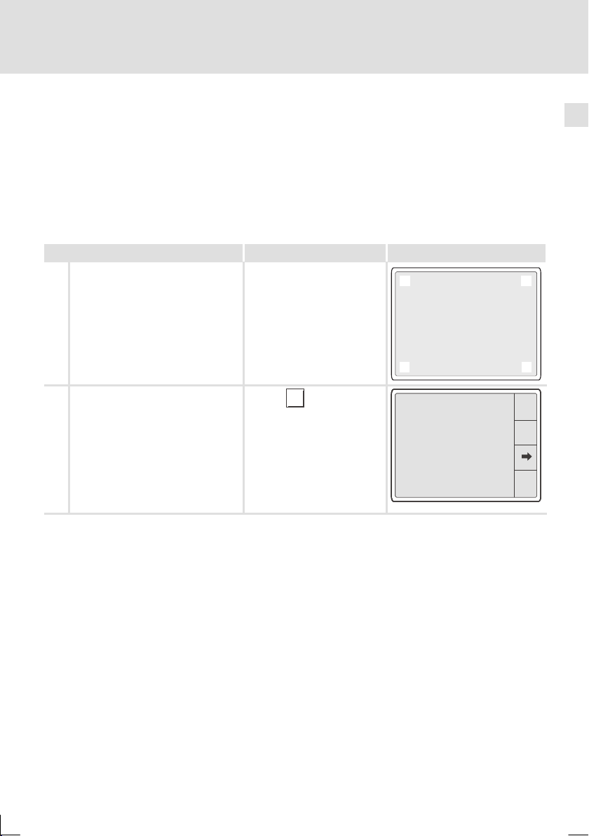
A ... Datum/Uhrzeit und Kontrast am Dis-
play einstellen.
1. Statusmeldungen aufrufen. Dazu
das Displayin den Ecken
–obenrechts und unten links
oder
– oben links und unten rechts
berühren.
Die erste zu berührende Ecke darf kein
anwählbares Feld enthalten.
2. Menüfür Uhrzeit/Datumund Kon-
trast anwählen.
B ... Datum/Uhrzeit einstellen.
1. Feld “SET CLOCK” berühren, um das
Menü anzuwählen.
PROG
2
1
Port : NET
Port : NET
Driver : CAN Lenze M
Driver : CAN Lenze M
Ver : 1.12
Ver : 1.12
Addr : NO ADDRESS
Addr : NO ADDRESS
Error : RESET
Error : RESET
SET CONTRAST : 04
SET CONTRAST : 04
SET CONTRAST : 04
SET CONTRAST : 04
SET CONTRAST : 04
SET CLOCK:
SET CLOCK:
SET CLOCK:
SET CLOCK:
SET CLOCK:
Wed,13/09/00
Wed,13/09/00
Wed,13/09/00
Wed,13/09/00
Wed,13/09/00
12:50:10
12:50:10
12:50:10
12:50:10
12:50:10
0
3
PROG
PROG
TRAN
TRAN
PAGE
PAGE
ESC
ESC
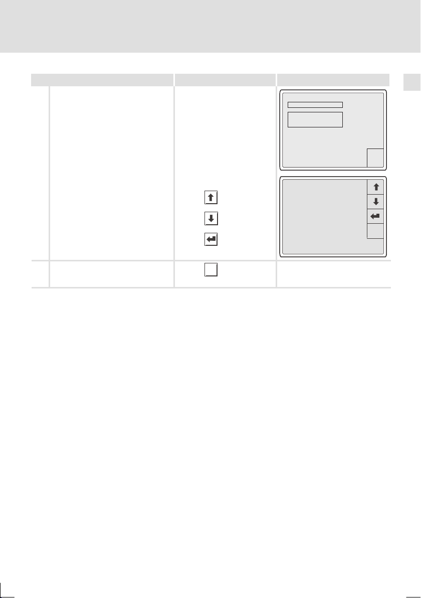
2. Gewünschtes Feld anwählen.
3. Wert ändern.
4. Ggf. Schritt 2. und 3. wiederholen,
um weitere Werte zu ändern.
5. Bestätigen Sie die Eingabe.
– Das Menü für Uhrzeit/Datum
und Kontrast wird angezeigt.
28
oder
oder
12:50:10 13/09/00
12:50:10 13/09/00
12:50:10 13/09/00
12:50:10 13/09/00
EDBPM-H515 DE/EN/FR 2.0
ESC
ESC
ESC
ESC
ESC
ESC
ESC
ESC
ESC
Page 29
C ... Kontrast am Display einstellen.
1. Feld “ SET CONTRAST” berühren, um
das Menü anzuwählen.
2. Kontrast einstellen.
mehr Kontrast
weniger Kontrast
3. Bestätigen Sie die Eingabe.
– Das Menü für Uhrzeit/Datum
und Kontrast wird angezeigt.
D ...Menü Datum/Uhrzeit und Kontrast
verlassen und die Statusanzeige
schließen.
Inbetriebnahme
Datum/Uhrzeit und Kontrast einstellen
BeispielBerühren Sie die Felder...Sie möchten ...
SET CONTRAST : 04
SET CONTRAST : 04
SET CLOCK:
SET CLOCK:
Wed,13/09/00
Wed,13/09/00
12:50:10
12:50:10
CONTRAST : 04
CONTRAST : 04
CONTRAST : 04
CONTRAST : 04
ESC
2x
ESC
ESC
ESC
ESC
ESC
ESC
5
EDBPM-H515 DE/EN/FR 2.0
29
Page 30

6
Bedienung
Tastenfunktionen
6 Bedienung
6.1 Tastenfunktionen
Tasten Funktion Erläuterung
9
0
...
SHIFT
+
1/A
+/-
ESC
6/F
...
.
<0> ... <9> Numerische Tasten für die Dateneingabe
<1/A> ... <6/F>
<+/-> Vorzeichen eingeben
<·> Gleitkomma eingeben
<ESC>
<Pfeil auf>
<Pfeil ab>
<Pfeil links>
<Pfeil rechts>
<Enter> Eingegebenen Wert übernehmen
Alphanumerische Tasten für die hexadezimale Dateneingabe
Parametereingabe abbrechen; Hilfe-, Informations-,
Alarm- und Statusmeldungen verlassen
Parameterebene:
Vorherigen dynamischen Text anwählen
Vorheriges alphanumerisches Zeichen anwählen
Parameterebene:
Nächsten dynamischen Text anwählen
Nächstes alphanumerisches Zeichen anwählen
Parameterebene: Cursor auf das vorherige Zeichen
stellen
Parameterebene: Cursor auf das nächste Zeichen
stellen
30
EDBPM-H515 DE/EN/FR 2.0
Page 31

Daten eingeben
f
–DerCursorstelltsichaufdi
e
Ineinemalphanumerischenoder
d
S
tel
l
hlink
6.2 Daten eingeben
Das Eingeben oder Ändern von Daten ist Schritt für Schritt dargestellt und wird an
einem Beispiel erläutert.
Sie möchten ... Berühren Sie die Felder... Beispiel
A ... ein Menü/eine Seite anwählen.
Berühren Sie das gewünschte Feld.
B ... in die Parameterebene wechseln.
Berühren Sie das Parameterfeld.
– Der Cursor stellt sich au
rechte Ziffer.
– In einem alphanumerischen oder
dynamischen Textfeld stellt sich
der Cursor auf das linke Zeichen
(siehe G oder J).
C
... einen numerischen Wert vollständig
die
neu eingeben.
1. Wechseln Sie in die Parameter-
ebene (siehe B).
2. Lassen Sie den Cursor auf der rech-
ten Ziffer stehen.
-9876
-9876
-9876
-9876
+/-
+/-
+/-
+/-
-9876
+/-
Bedienung
0
0
0
0
1
1
1
1
.
.
.
.
4
4
4
4
7
7
7
7
0
1
.
4
7
6
ESC
ESC
ESC
ESC
3
3
3
3
2
2
2
2
5
5
5
5
6
6
6
6
8
9
8
9
8
9
8
9
ESC
3
2
5
6
8
9
3. Geben Sie den Wert der ersten
Stelle ein.
...
0
9
0001
0001
0001
– Alle anderen Stellen werden auf
Null gesetzt.
ESC
ESC
ESC
3
3
3
6
6
6
9
9
9
4. Geben Sie den Wert der nächsten
Stelle ein.
0
0
0
1
1
1
2
2
2
.
.
.
+/-
+/-
+/-
...
0
9
0012
0012
0012
5
5
5
4
4
4
7
7
7
8
8
8
– Die eingegebenen Ziffern wer-
en eine
schoben.
enac
EDBPM-H515 DE/EN/FR 2.0
sge-
-
ESC
ESC
ESC
3
3
3
6
6
6
9
9
9
31
+/-
+/-
+/-
0
0
0
1
1
1
2
2
2
.
.
.
5
5
5
4
4
4
7
7
7
8
8
8
Page 32

6
Bedienung
Daten eingeben
5. Geben Sie ggf. ein Gleitkomma ein.
Hinweis:
Sie können ein Gleitkomma nur einfügen, wenn das Feld als “Floating Point”
definiert ist (siehe Projektierungstool
»HMI Designer«).
6. Wiederholen Sie Schritt 4. bis Sie
den Wert vollständig eingegeben
haben.
7. Geben Sie ggf. ein Vorzeichen ein.
+/-
BeispielBerühren Sie die Felder...Sie möchten ...
012.
.
012.
0
0
.
.
+/-
+/-
-12.34
-12.34
ESC
ESC
3
1
1
4
4
7
7
3
2
2
5
5
6
6
8
9
8
9
8. Bestätigen Sie die Eingabe.
– Der Cursor wechselt in die Menü-
ebene.
D
... eine einzelne numerische Ziffer ändern.
1. Wechseln Sie in die Parameter-
ebene (siehe B).
2. Wählen Sie die gewünschte Ziffer.
3. Ändern Sie die Ziffer.
4. Bestätigen Sie die Eingabe.
– Der Cursor wechselt in die Menü-
ebene.
ESC
ESC
3
0
0
1
1
.
.
4
4
7
7
+/-
+/-
12. 49
12. 49
12. 49
0
9
...
0
0
0
1
1
1
.
.
.
4
4
4
7
7
7
+/-
+/-
+/-
3
2
2
5
5
6
6
8
9
8
9
ESC
ESC
ESC
3
3
3
2
2
2
5
5
5
6
6
6
8
8
8
9
9
9
32
EDBPM-H515 DE/EN/FR 2.0
Page 33

E
... einen hexadezimalen Wert vollständig neu eingeben.
1. Wechseln Sie in die Parameter-
ebene (siehe B).
2. Lassen Sie den Cursor auf der rech-
ten Ziffer stehen.
Bedienung
Daten eingeben
BeispielBerühren Sie die Felder...Sie möchten ...
1A3F
0
1/A
4/D
SHIFT
7
2/B
5/E
6
ESC
3/C
6/F
9
8
3. Geben Sie den Wert der ersten
Stelle ein.
– Alle anderen Stellen werden auf
Null gesetzt.
numerischer Wert
alphanumerischer Wert
4. Geben Sie den Wert der nächsten
Stelle ein.
– Die zuvor eingegebenen Ziffern
werden eine Stelle nach links ge-
schoben.
numerischer Wert
alphanumerischer Wert
5. Wiederholen Sie Schritt 4. bis Sie
den Wert vollständig eingegeben
haben.
6. Bestätigen Sie die Eingabe.
– Der Cursor wechselt in die Menü-
ebene.
F
... eine einzelne hexadezimale Ziffer
ändern.
1. Wechseln Sie in die Parameter-
ebene (siehe B).
2. Wählen Sie die gewünschte Ziffer.
3. Ändern Sie die Ziffer.
numerischer Wert
alphanumerischer Wert
4. Bestätigen Sie die Eingabe.
– Der Cursor wechselt in die Menü-
ebene.
SHIFT
SHIFT
SHIFT
000B
000B
000B
ESC
ESC
0
0
0
1/A
2/B
1/A
2/B
1/A
0
+
1/A
0
+
1/A
0
+
1/A
9
...
SHIFT
SHIFT
6/F
...
9
...
6/F
...
9
...
6/F
...
SHIFT
00BD
00BD
00BD
00BD
0
0
0
0
SHIFT
SHIFT
SHIFT
SHIFT
13FC
13FC
13FC
13FC
13FC
SHIFT
SHIFT
SHIFT
SHIFT
SHIFT
0
0
0
0
0
4/D
4/D
4/D
1/A
1/A
1/A
1/A
4/D
4/D
4/D
4/D
1/A
1/A
1/A
1/A
1/A
4/D
4/D
4/D
4/D
4/D
2/B
5/E
5/E
5/E
7
7
7
8
8
8
2/B
2/B
2/B
2/B
5/E
5/E
5/E
5/E
7
7
7
7
8
8
8
8
2/B
2/B
2/B
2/B
2/B
5/E
5/E
5/E
5/E
5/E
7
7
7
7
7
8
8
8
8
8
3/C
3/C
3/C
6/F
6/F
6/F
3/C
3/C
3/C
3/C
6/F
6/F
6/F
6/F
3/C
3/C
3/C
3/C
3/C
6/F
6/F
6/F
6/F
6/F
ESC
9
9
9
ESC
ESC
ESC
ESC
9
9
9
9
ESC
ESC
ESC
ESC
ESC
9
9
9
9
9
EDBPM-H515 DE/EN/FR 2.0
33
Page 34

6
–DerCursorwechseltindieMenü
-
Bedienung
Daten eingeben
G
... einen alphanumerischen Wert ändern.
1. Wechseln Sie in die Parameter-
ebene (siehe Schritt B).
2. Wählen Sie das gewünschte Zei-
chen.
3. Ändern Sie das Zeichen.
nächster Buchstabe im Alphabet
vorheriger Buchstabe im Alphabet
4. Wiederholen Sie Schritt 3. bis der
neue Wert eingegeben ist(z. B
“VALVE”).
5. Geben Sie ggf. eine Ziffer ein.
nächste Ziffer
oder
BeispielBerühren Sie die Felder...Sie möchten ...
MOTOR1
MOTOR1
MOTOR1
MOTOR1
MOTOR1
MOTOR1
MOTOR1
MOTOR1
MOTOR1
MOTOR1
MOTOR1
MOTOR1
MOTOR1
MOTOR1
MOTOR1
MOTOR1
VOTOR1
VOTOR1
VOTOR1
VOTOR1
VOTOR1
VOTOR1
VOTOR1
VOTOR1
VOTOR1
VOTOR1
VOTOR1
VOTOR1
VOTOR1
VOTOR1
VOTOR1
VOTOR1
ESC
ESC
ESC
ESC
ESC
ESC
ESC
ESC
ESC
ESC
ESC
ESC
ESC
ESC
ESC
ESC
ESC
ESC
ESC
ESC
ESC
ESC
ESC
ESC
ESC
ESC
ESC
ESC
ESC
ESC
ESC
ESC
vorherige Ziffer
6. Bestätigen Sie die Eingabe.
– Der Cursor wechselt in die Menü-
ebene.
H ... einen binären Wert vollständig neu
eingeben.
1. Wechseln Sie in die Parameter-
ebene (siehe B).
2. Geben Sie den neuen Wert ein wie
in C beschrieben.
I ... eine einzelne binäre Ziffer ändern.
1. Wechseln Sie in die Parameter-
ebene (siehe B).
2. Geben Sie den neuen Wert ein wie
in D beschrieben.
VALVE3
VALVE3
VALVE3
VALVE3
VALVE3
VALVE3
VALVE3
VALVE3
VALVE3
VALVE3
VALVE3
VALVE3
VALVE3
VALVE3
VALVE3
VALVE3
0001
0
1101
0
ESC
ESC
ESC
ESC
ESC
ESC
ESC
ESC
ESC
ESC
ESC
ESC
ESC
ESC
ESC
ESC
1
1
ESC
ESC
34
EDBPM-H515 DE/EN/FR 2.0
Page 35

J
DerCursorwechseltindieMen
ü
... ein dynamisches Textfeld ändern.
1. Wechseln Sie in die Parameter-
ebene (siehe B).
2. Wählen Sie den Text aus.
nächster Text
Bedienung
Daten eingeben
BeispielBerühren Sie die Felder...Sie möchten ...
ON
ON
ON
ON
6
vorheriger Text
3. Bestätigen Sie die Eingabe.
– Der Cursor wechselt in die Menü-
ebene.
K
...einSymbolineinemSymbolfeldändern.
1. Wechseln Sie in die Parameter-
ebene (siehe B).
2. Ändern Sie das Symbol. (z. B. C, D,
F, G)
nächstes Symbol
vorheriges Symbol
3. Bestätigen Sie die Eingabe.
– Der Cursor wechselt in die Menü-
ebene.
L
... einen Wert über ein Balkendiagramm eingeben.
1. Wechseln Sie in die Parameter-
ebene (siehe B).
2. GebenSiedenWertein.
– “VAL” zeigt den eingegebenen
Wert numerisch an.
3. Bestätigen Sie die Eingabe.
– Der Cursor wechselt in die Menü-
ebene.
oder
ESC
ESC
ESC
ESC
ESC
ESC
ESC
VAL:36
VAL:36
VAL:36
ESC
ESC
ESC
ESC
[
[
[
[
MAX:100Min:0
MAX:100Min:0
MAX:100Min:0
EDBPM-H515 DE/EN/FR 2.0
35
Page 36

6
Bedienung
Informationsmeldung aufrufen
6.3 Informationsmeldung aufrufen
ƒ
Informationsmeldungen
–
sind Texte, die aufgrund eines Ereignisses angezeigt werden (z. B., wenn
ein Istwert eine Grenze übersteigt).
–
können Sie nur aufrufen, solange das auslösende Ereignis vorhanden ist.
–
müssen im Projektierungstool »HMI Designer« programmiert worden sein.
–
können max. 4 Zeilen à 70 Zeichen lang sein (einfache Zeichengröße).
ƒ
Die zweitletzte Zeile enthält ein programmierbares Meldungsfeld. Dieses
Feld zeigt die numerische Größe der Variablen, die die Meldung aktiviert hat.
ƒ
Die letzte Zeile zeigt Datum und Uhrzeit, wann die Meldung ausgelöst
wurde.
ƒ
signalisiert, wenn eine Informationsmeldung vorhanden ist.
Symbole und Zeichen in den Informationsmeldungen
Symbole/Zeichen in der Zeile Datum/Uhrzeit Bedeutung
Die Informationsmeldung wurde zum ersten Mal auf-
HELP Der Informationsmeldung ist eine Hilfe zugeordnet.
Sie möchten ... Berühren Sie die Felder... Beispiel
A ... eine Informationsmeldung aufrufen.
gerufen
E
39)
(
Druck uebersteigt
die Sicherheitsgrenze
125.5
13-09-2000 10:45a HELP
Temperatur uebersteigt
die Sicherheitsgrenze
1700
13-09-2000 10:55a HELP
ESC
B
... die nächsten Informationsmeldungen anwählen.
C ... die Informationsmeldungen schlie-
ßen.
36
ESC
oder
Wasserstand unterhalb
Wasserstand unterhalb
Wasserstand unterhalb
Wasserstand unterhalb
Wasserstand unterhalb
Wasserstand unterhalb
Wasserstand unterhalb
der Mindestgrenze
der Mindestgrenze
der Mindestgrenze
der Mindestgrenze
der Mindestgrenze
der Mindestgrenze
der Mindestgrenze
-10
-10
-10
-10
-10
-10
-10
13-09-2000 11:00a HELP
13-09-2000 11:00a HELP
13-09-2000 11:00a HELP
13-09-2000 11:00a HELP
13-09-2000 11:00a HELP
13-09-2000 11:00a HELP
13-09-2000 11:00a HELP
EDBPM-H515 DE/EN/FR 2.0
ESC
ESC
ESC
ESC
ESC
ESC
ESC
Page 37

6.4 Alarmmeldungen aufrufen
ƒ
Alarmmeldungen
–
sind Texte, die aufgrund eines Ereignisses angezeigt werden (z. B., wenn
ein Istwert eine Grenze übersteigt),
–
müssen im Projektierungstool »HMI Designer« programmiert worden sein,
–
können max. 4 Zeilen à 70 Zeichen lang sein (einfache Zeichengröße),
–
werden in einem Alarmregister chronologisch nach Datum und Uhrzeit
gespeichert.
ƒ
Die zweitletzte Zeile enthält ein programmierbares Meldungsfeld. Dieses
Feld zeigt die numerische Größe der Variablen, die die Meldung aktiviert hat.
ƒ
Die letzte Zeile zeigt Datum und Uhrzeit, wann die Meldung ausgelöst
wurde.
ƒ
signalisiert, wenn eine Alarmmeldung vorhanden ist.
Symbole und Zeichen in den Alarmmeldungen
Symbole1)Zeichen in der Zeile Datum/Uhrzeit Bedeutung
> Nicht quittierter Alarm
# Quittierter Alarm, jedoch Alarmursache noch vor-
< Nicht quittierter Alarm, jedoch Alarmursache nicht
HELP Der Alarmmeldung ist eine Hilfe zugeordnet.
1) Wenn eine Alarmmeldung mehrfach eingegangen ist, signalisiert das Symbol die zuletzt
eingegangene Meldung.
Bedienung
Alarmmeldungen aufrufen
handen
mehr voranden
E
39)
(
6
EDBPM-H515 DE/EN/FR 2.0
37
Page 38

6
g
g
desAlarmschronologischnachD
a
,
siert,dassdasAlarmregisterang
e
Bedienung
Alarmmeldungen aufrufen
Sie möchten ... Berühren Sie die Felder... Beispiel
A ... eine Alarmmeldung aufrufen.
0001
0006
0032
Druck uebersteigt
die Sicherheitsgrenze
125.5
>13-09-2000 10:45a HELP
Temperatur uebersteigt
die Sicherheitsgrenze
1600
>13-09-2000 10:55a
<13-09-2000 10:58a HELP
Wasserstand unterhalb
der Mindestgrenze
-10
>13-09-2000 11:00a
#13-09-2000 11:05a HELP
ESC
HIST
B ... das Alarmregister zu einer Alarm-
meldung anwählen.
Im Alarmregister ist das Auftreten
desAlarmschronolo
tum und Uhrzeit gespeichert.
Ein “H” in der linken Spalte signali-
dass das Alarmregister ange-
siert
wählt ist.
Alarmregister schließen und zur
isch nach Da-
Alarmmeldungzurückkehren.
C ... die Alarmmeldungen schließen.
Hinweis!
ƒ
Wenn der Puffer des Alarmregisters voll ist, werden keine weiteren
Alarme gespeichert.
ƒ
Im »HMI Designer« können Sie Befehlsbereiche definieren, um alle
Alarme zu quittieren oder den Puffer des Alarmregisters zu leeren.
HIST
-
-
ESC
ESC
Druck uebersteigt
Druck uebersteigt
Druck uebersteigt
Druck uebersteigt
Druck uebersteigt
Druck uebersteigt
Druck uebersteigt
H
H
H
H
H
H
H
die Sicherheitsgrenze
die Sicherheitsgrenze
die Sicherheitsgrenze
die Sicherheitsgrenze
die Sicherheitsgrenze
die Sicherheitsgrenze
die Sicherheitsgrenze
125.5
125.5
125.5
125.5
125.5
125.5
125.5
0001
0001
0001
0001
0001
0001
0001
>13-09-2000 10:45a
>13-09-2000 10:45a
>13-09-2000 10:45a
>13-09-2000 10:45a
>13-09-2000 10:45a
>13-09-2000 10:45a
>13-09-2000 10:45a
<13-09-2000 10:48a
<13-09-2000 10:48a
<13-09-2000 10:48a
<13-09-2000 10:48a
<13-09-2000 10:48a
<13-09-2000 10:48a
<13-09-2000 10:48a
H
H
H
H
H
H
H
Temperatur uebersteigt
Temperatur uebersteigt
Temperatur uebersteigt
Temperatur uebersteigt
Temperatur uebersteigt
Temperatur uebersteigt
Temperatur uebersteigt
die Sicherheitsgrenze
die Sicherheitsgrenze
die Sicherheitsgrenze
die Sicherheitsgrenze
die Sicherheitsgrenze
die Sicherheitsgrenze
die Sicherheitsgrenze
1600
1600
1600
1600
1600
1600
1600
0006
0006
0006
0006
0006
0006
0006
>13-09-2000 10:55a
>13-09-2000 10:55a
>13-09-2000 10:55a
>13-09-2000 10:55a
>13-09-2000 10:55a
>13-09-2000 10:55a
>13-09-2000 10:55a
<13-09-2000 10:58a
<13-09-2000 10:58a
<13-09-2000 10:58a
<13-09-2000 10:58a
<13-09-2000 10:58a
<13-09-2000 10:58a
<13-09-2000 10:58a
H
H
H
H
H
H
H
Wasserstand unterhalb
Wasserstand unterhalb
Wasserstand unterhalb
Wasserstand unterhalb
Wasserstand unterhalb
Wasserstand unterhalb
Wasserstand unterhalb
der Mindestgrenze
der Mindestgrenze
der Mindestgrenze
der Mindestgrenze
der Mindestgrenze
der Mindestgrenze
der Mindestgrenze
-10
-10
-10
-10
-10
-10
-10
0032
0032
0032
0032
0032
0032
0032
>13-09-2000 11:00a
>13-09-2000 11:00a
>13-09-2000 11:00a
>13-09-2000 11:00a
>13-09-2000 11:00a
>13-09-2000 11:00a
>13-09-2000 11:00a
#13-09-2000 11:05a
#13-09-2000 11:05a
#13-09-2000 11:05a
#13-09-2000 11:05a
#13-09-2000 11:05a
#13-09-2000 11:05a
#13-09-2000 11:05a
ESC
ESC
ESC
ESC
ESC
ESC
ESC
38
EDBPM-H515 DE/EN/FR 2.0
Page 39

6.5 Hilfe aufrufen
ƒ
Hilfemeldungen
–
können Seiten- oder Informationsmeldungen zugeordnet sein,
–
enthalten nützliche Hinweise, die die Bedienung erleichtern,
–
müssen im Projektierungstool »HMI Designer« programmiert worden sein,
–
für Informationsmeldungen können max. 16 Zeilen à 74 Zeichen lang sein
(einfache Zeichengröße),
–
für Projektseiten können max. 16 Zeilen à 80 Zeichen lang sein (einfache
Zeichengröße).
Sie möchten ... Berühren Sie die Felder... Beispiel
A
... die Hilfe zu einer Informationsmeldung aufrufen.
1. Berühren Sie das programmierte
Feld “HELP”.
2. Hilfe schließen.
B
... die Hilfe zu einer Seite aufrufen.
1. Berühren Sie das programmierte
Feld, welches mit der Funktion “Hilfeseite öffnen” belegt ist.
2. Hilfe schließen.
ESC
ESC
Bedienung
Hilfe aufrufen
Druck uebersteigt
Druck uebersteigt
die Sicherheitsgrenze
die Sicherheitsgrenze
125.5
125.5
13-09-2000 10:45a HELP
13-09-2000 10:45a HELP
Temperatur uebersteigt
Temperatur uebersteigt
die Sicherheitsgrenze
die Sicherheitsgrenze
1700
1700
13-09-2000 10:55a HELP
13-09-2000 10:55a HELP
ESC
ESC
6
EDBPM-H515 DE/EN/FR 2.0
39
Page 40

6
6.6 Daten sichern auf 8 MB Memory Card
Bedienung
Daten sichern auf 8 MB Memory Card
ƒ
Auf diesen Speicherbaustein können Sie Ihr anwendungsspezifisch
konfiguriertes Projekt sichern und archivieren.
ƒ
Sie können den Speicherbaustein mit dem gesicherten Projekt in eine
Bedieneinheit gleichen Typs einbauen, um das Projekt in diese Bedieneinheit
zu übertragen.
ƒ
Die folgende Bedienung steht Ihnen nur zur Verfügung, wenn die Memory
Card in die Bedieneinheit eingebaut ist. (Q 21)
40
EDBPM-H515 DE/EN/FR 2.0
Page 41

Daten sichern auf 8 MB Memory Card
Sie möchten ... Berühren Sie die Felder... Beispiel
A
... auf die Memory Card zugreifen.
1. Statusmeldungen aufrufen. Dazu
das Display in den Ecken
–obenrechts und unten links
oder
– oben links und unten rechts
berühren.
Die erste zu berührendeEcke darf kein
anwählbares Feld enthalten.
2. Transfer Page anwählen.
3. MenüMemoCARD anwählen.
TRAN
PAGE
MemoCARD
2
2
2
2
2
1
1
1
1
1
Port : NET
Port : NET
Port : NET
Port : NET
Port : NET
Driver : CAN Lenze M
Driver : CAN Lenze M
Driver : CAN Lenze M
Driver : CAN Lenze M
Driver : CAN Lenze M
Ver : 1.12
Ver : 1.12
Ver : 1.12
Ver : 1.12
Ver : 1.12
Addr : NO ADDRESS
Addr : NO ADDRESS
Addr : NO ADDRESS
Addr : NO ADDRESS
Addr : NO ADDRESS
Error : RESET
Error : RESET
Error : RESET
Error : RESET
Error : RESET
H521 TRANSFER PAGE
H521 TRANSFER PAGE
H521 TRANSFER PAGE
H521 TRANSFER PAGE
H521 TRANSFER PAGE
Touchscreen BOOT check: OK
Touchscreen BOOT check: OK
Touchscreen BOOT check: OK
Touchscreen BOOT check: OK
Touchscreen BOOT check: OK
Graphic controller BOOT check: OK
Graphic controller BOOT check: OK
Graphic controller BOOT check: OK
Graphic controller BOOT check: OK
Graphic controller BOOT check: OK
Graphic controller RAM check: OK
Graphic controller RAM check: OK
Graphic controller RAM check: OK
Graphic controller RAM check: OK
Graphic controller RAM check: OK
Main BOOT and RAM check: WAIT
Main BOOT and RAM check: WAIT
Main BOOT and RAM check: WAIT
Main BOOT and RAM check: WAIT
Main BOOT and RAM check: WAIT
SELECT: MSP EXITMemoCARD
SELECT: MSP EXITMemoCARD
SELECT: MSP EXITMemoCARD
SELECT: MSP EXITMemoCARD
SELECT: MSP EXITMemoCARD
Bedienung
0
0
0
0
0
3
3
3
3
3
PROG
PROG
PROG
PROG
PROG
TRAN
TRAN
TRAN
TRAN
TRAN
PAGE
PAGE
PAGE
PAGE
PAGE
ESC
ESC
ESC
ESC
ESC
6
B
... Funktion anwählen.
BACKUP
– Projekt von der Bedieneinheit
auf den Speicherbaustein sichern
ERASE
– Inhalt des Speicherbausteins lö-
schen
RESTORE
– Inhalt des Speicherbausteins auf
die Bedieneinheit übertragen
EXIT
– MEMORY CARD MENU verlassen
C ...dieTransferPageverlassen
EDBPM-H515 DE/EN/FR 2.0
BACKUP
ERASE
RESTORE
EXIT
EXIT
MEMORY CARD MENU
MEMORY CARD MENU
MEMORY CARD MENU
MEMORY CARD MENU
MEMORY CARD MENU
BACKUP
BACKUP
BACKUP
BACKUP
BACKUP
ERASE
ERASE
ERASE
ERASE
ERASE
RESTORE
RESTORE
RESTORE
RESTORE
RESTORE
EXIT
EXIT
EXIT
EXIT
EXIT
41
Page 42

7
i
k
h
lerhaf
ü
f
g
(
gy()p
tembus(CAN)
(
,
(
g
unterbroche
n
derSchnittstelle(Baudrate
gne
r-ErsteSchritte
)
desse,dete)
Fehlersuche und Störungsbeseitigung
Störungsmeldungen
7 Fehlersuche und Störungsbeseitigung
7.1 Störungsmeldungen
Rufen Sie dieStatusmeldungen der Bedieneinheit auf, um die zuletzt aufgetretene
Störungsmeldung anzuzeigen. (Q 27)
Display Störung Ursache Abhilfe
NO ERROR Keine Störung - -
PR ERROR Fehlerhafter
COM BROK Kommunika-
A-ASIC ko1 Kommun
ASIC ko2
ASIC ko3
ASIC ko4
RESET
SDOERR 6
SDOERR 5
SDOERR 3
Datenaustausch
tion unterbrochen
tion mit Sys-
unterbrochen
Verbindung zwischen Bedieneinheit und PC ist fehlerhaft
Serielles Datenkabelzwischen
Bedieneinheit und PC ist defekt
oder nicht richtig angeschlossen
a-
Fe
te Verdrahtung(z. B.Verdrahtung Systembus(CAN)pr
Verpolung) des Systembus
Fehlerhafte Parametrierung
der Schnittstelle
Adresse, Identifier)
Baudrate
Anschlüsse auf festen Sitz prüfen
Leitung auf Beschädigung kontrollieren
Sub-D-Stecker auf richtigen Anschluss
und festen Sitz prüfen
Serielles Datenkabel austauschen
(E20)
Parametrierung prüfen
,
ner - Erste Schritte).
.
E
HMI Desi-
en
42
EDBPM-H515 DE/EN/FR 2.0
Page 43

8Wartung
Die Bedieneinheit ist wartungsfrei, wenn die vorgeschriebenen Einsatzbeding ungen eingehalten werden. (Q 10)
ƒ
Reinigen Sie die Bedieneinheit mit denaturiertem Äthylalkohol.
ƒ
Wenn Sie ein anderes Reinigungsmittel verwenden müssen, um
Verunreinigungen zu beseitigen, beachten Sie die Angaben in der Tabelle im
Kap. 9.1. (Q 44)
Wartung 8
EDBPM-H515 DE/EN/FR 2.0
43
Page 44

9
Anhang
Chemikalienbeständigkeit
9 Anhang
9.1 Chemikalienbeständigkeit
Stop!
Die Bedien-Oberfläche ist wenig beständig gegen saure
Nahrungsmittel (z. B. Tomatensaft, Zitronensaft). Verschmutzungen
deshalb gleich entfernen, sonst kann die Oberfläche beschädigt
werden.
Die folgende Tabellezeigt die Beständigkeit der Bedien-Oberfläche (Tastatur, Display, Touch Screen) gegen die genannten Chemikalien.
Für die Bedieneinheiten EPM-H5xx und EPM-H6xx bietet Lenze Schutzfolien an,
mit einer verbesserten Beständigkeit gegen die genannten Chemikalien.
Substanz
Aceton — ☺
Ameisensäure ≥ 50 % — —
Ammoniak ≥ 2% — —
Äthylenglykol —
Ätznatron ≥ 2% — —
Benzin ☺ ☺
Benzol ☺ ☺ ☺
Benzylalkohol — —
Beizlösung konzentriert — — —
Chlorwasserstoffsäure ≥ 10 % — —
Dieselöl ☺ ☺ ☺ ☺
Eisessig — —
Essigsäure ≥ 5%<50% ☺
Ethanol ☺
Hochdruck und Temperatur > 100 °C
Isopropanol ☺ ☺ ☺
Methanol ☺ ☺ —
Methylenchlorid — —
Mineralsäuren konzentriert — —
Natriumhydroxid ≥ 50 % —
Perchlorethylen — — ☺
Bedieneinheit
EPM-H3xx EPM-H4xx EPM-H5xx
EPM-H6xx
— —
mit Schutz-
folie
44
EDBPM-H515 DE/EN/FR 2.0
Page 45

Anhang
Chemikalienbeständigkeit
Bedieneinheit
Substanz
Substanz
Phosphorsäure ≥ 30 %
Salpetersäure ≥ 5%<10% ☺
Schwefelsäure ≥ 50 %
Toluol ☺ ☺ ☺
Trichlorethylen — — ☺
Unterchlorigsaures Natron ≥ 20 % — —
Wasserstoffsuperoxyd ≥ 25 % — —
EPM-H3xx EPM-H310, EPM-H312, EPM-H315
EPM-H4xx EPM-H410
EPM-H5xx EPM-H502, EPM-H505, EPM-H507, EPM-H510, EPM-H515, EPM-H520,
EPM-H6xx EPM-H605
☺ Oberfläche ist beständig, keine sichtbare Beschädigung
Oberfläche ist nicht beständig, wird beschädigt
—nichtgetestet
EPM-H521, EPM-H525
EPM-H4xxEPM-H3xx
EPM-H5xx
EPM-H6xx
mit Schutz-
folie
9
EDBPM-H515 DE/EN/FR 2.0
45
Page 46

9
Anhang
Stichwortverzeichnis
9.2 Stichwortverzeichnis
A
Abmessungen, 17
Alarmmeldungen, 37
Anschluss, elektischer, 11
Anschlussklemmen, Belegung, 19
Antriebsregler, 8
Approbation, 10
B
Backup, auf Memory Card 8 MB, 40
Backup-Karte, einbauen, 21
Bedieneinheit
- Alarmmeldung aufrufen, 37
- Daten eingeben, 31
- Eigenschaften, 12
- Funktion der Tasten, 30
- Hilfe aufrufen, 39
- Informationsmeldung aufrufen, 36
- Projekt in die übertragen, 24
- Schnittstellenbeschreibung, 16
- Statusmeldungen, 27
- Verbindung zum PC entfernen, 26
- Verbindung zum PC herstellen, 24
Bedieneinheit befestigen, 18
Bedienung, 30
Begriffsdefinitionen, 8
C
Chemikalienbeständigkeit, 44
D
Daten, eingeben, 31
Daten sichern, auf 8 MB Memory Card, 40
Datum, einstellen, 28
DC-Spannungsversorgung, 11
Display, 11
- Kontrast einstellen, 28
E
Eigenschaften, 12
Einbauausschnitt, 17
Einbauen, Memory Card 8 MB, 22
Einsatzbedingungen
-Feuchte,10
- Schutzart, 10
Einschalten, erstes, 23
Elektrische Daten, 11
Elektrische Installation, 19
- Belegung der Anschlussklemmen, 19
Erstes Einschalten, 23
F
Fehlersuche, 42
- Störungsmeldungen, 42
H
Hilfemeldung, 39
Human Machine Interface, 8
46
EDBPM-H515 DE/EN/FR 2.0
Page 47

Anhang
Stichwortverzeichnis
9
I
Inbetriebnahme, 23
- erstes Einschalten, 23
Informationsmeldungen, 36
Installation, Systembus (CAN), 20
Installation, elektrische, 19
Installation, mechanische, 18
K
Kabeltyp, 20
Kapazitätsbelag, 20
Klimatische Bedingungen, 10
Konformität, 10
Kontrast, einstellen, 28
L
Leistungsaufnahme, 11
Leitungswiderstand, 20
M
Masse, 10
Mechanische Installation, 18
Memory Card, einbauen, 21
Memory Card 8 MB, Backup, 40
P
PC
- Verbindung zur Bedieneinheit entfernen, 26
- Verbindung zur Bedieneinheit herstellen, 24
Projekt, in die Bedieneinheit übertragen, 24
Projekt-Download, 25
S
Schutzart, 10
Sicherheitshinweise, 9
Speicher, 11
Speichererweiterung, einbauen, 21
Statusmeldungen, 27
Störungsbeseitigung, 42
Störungsmeldungen, 42
Systembus ( CAN)
- Kommunikationsmedium, 11
- Verdrahtung, 20
T
Tastenfunktionen, 30
Technische Daten, 10
- Abmessungen, 17
- DC-Spannungsversorgung, 11
-Display,11
- Einbauausschnitt, 17
- Elektrische Daten, 11
- elektrischer Anschluss, 11
- Leistungsaufnahme, 11
- Masse, 10
- Schnittstellenbeschreibung, 16
-Speicher,11
- Systembus (CAN), 11
Temperaturbereiche, 10
- Bemessungsstrom reduzieren, 10
U
Uhrzeit, einstellen, 28
W
Wartung, 43
EDBPM-H515 DE/EN/FR 2.0
47
Page 48

Pos. Description Function
Terminal strip, 5-pole System bus (CAN)
DB25 socket MSPserial port for PC or PLC
DB25 socket LPT parallel port for printer
Terminal strip, 4-pole DC voltage supply 24 V
48
EDBPM-H515 DE/EN/FR 2.0
Page 49

This documentation applies to the EPM-H515 operating unit as of the version
Type EPM - H515 1A 10
Product range
EPM Operating unit
Hardware version
Software version
What’s new?
Version ID no. Changes
2.0 06/2005 TD 31 13036507 Series version
© 2005 Lenze Drive Systems GmbH, Hans-Lenze-Straße 1, D-31855 Aerzen
No part of this documentation may be reproduced or made accessible to third parties without written consent by
Lenze Drive Systems GmbH.
All information given in this documentation has been selected carefully and complies with the hardware and software
described. Nevertheless, deviations cannot be ruled out. We do not take any responsibility or liability for damages
which might possibly occur. Necessary corrections will be included in subsequent editions.
EDBPM-H515 DE/EN/FR 2.0
49
Page 50

Contentsi
1 Preface and general information 52.....................................
1.1 About these Operating Instructions 52.............................
1.2 Terminology used 52...........................................
1.3 Scope of supply 52.............................................
1.4 Layout of the safety instructions 53...............................
2 Technical data 54....................................................
2.1 General data/operating conditions 54.............................
2.2 Electrical data 55..............................................
2.2.1 Features of the operating unit 56........................
2.2.2 Interface description 59...............................
2.3 Dimensions 60.................................................
2.4 Mounting cutout 60............................................
3 Mechanical installation 61.............................................
3.1 Attaching operating unit 61......................................
4 Electrical installation 62...............................................
4.1 Assignment of the terminals 62..................................
4.2 Wire system bus (CAN) 63.......................................
4.3 Memory card mounting 64.......................................
4.3.1 Memory card 8 MB (backup) 64.........................
5 Commissioning 66...................................................
5.1 First switch-on 66..............................................
5.2 Project transfer to the operating unit 67............................
5.2.1 Connecting operating unit and PC 67.....................
5.2.2 Project download 68...................................
5.2.3 Disconnecting from the PC 69..........................
5.3 Status messages of the operating unit 70..........................
5.4 Date/Time and contrast setting 71................................
6Operation 73........................................................
6.1 Key functions 73...............................................
6.2 Data input 74.................................................
6.3 Calling up information messages 79..............................
6.4 Calling up alarm messages 80....................................
6.5 Calling up help messages 82.....................................
6.6 Save data on 8 MB memory card 83...............................
50
EDBPM-H515 DE/EN/FR 2.0
Page 51

Contents i
7 Troubleshooting and fault elimination 85................................
7.1 Fault messages 85..............................................
8 Maintenance 86......................................................
9 Appendix 87.........................................................
9.1 Chemical resistance 87.........................................
9.2 Index 89.....................................................
EDBPM-H515 DE/EN/FR 2.0
51
Page 52

1
55opeatgu
t
teeceptotedeey,cecedateyete
L
yliabilityfordef
ici
6screwsM4×35m
m
claimedsubsequently
1seal
f
y
p
f
)
forwarder
1
5-poleterminalstripforsystembus(CAN
)
visibledeficiencies/incompletenessimmediatelyto
Preface and general information
About these Operating Instructions
1 Preface and general information
This EPM-H515 operating unit enables you toaccess codes ofLenze controllers and
to control them easily. Communication takes places via the system bus (CAN).
The»HMIDesigner«Lenzesoftwareallowsforeasy programmingoftheoperating
unit.
1.1 About these Operating Instructions
ƒ
These Operating Instructions describe safe and trouble-free working on and
with the EPM-H515 operating unit.
ƒ
All persons working on and with the EPM-H515 operating unit must have
these Operating Instructions available and observe all relevant information
and notes.
ƒ
These Operating Instructions must always be kept as a complete document
and in a readable state.
1.2 Terminology used
Term Used in this text for
Drive controller Lenze frequency inverter 8200 vector and 9300 vector, servo inverter
HMI Human Machine Interface
9300 and 9400
1.3 Scope of supply
Quantity Important
1 EPM-H515 operating unit After receipt of the delivery, check immediately whether
1 Operating Instructions
6 mounting clamps
6screwsM4×35mm
1seal
1 4-pole terminal strip for connection of DC
voltage suppl
15-pole terminal stri
connection
or system bus(CAN
52
the items delivered match the accompanying papers.
enzedoes notacceptan
claimed subsequently.
Claim
visible transport damage immediately to the
orwarder.
visible deficiencies/incompleteness immediately to
your Lenze representative.
.
.
EDBPM-H515 DE/EN/FR 2.0
encies
Page 53

Preface and general information
1.4 Layout of the safety instructions
Thefollowingsignal words and symbols are used inthisdocumentationtoindicate
dangers and important information:
Safety instructions
Structure of safety instructions:
Danger!
(characterises the type and severity of danger)
Note
(describes the danger and gives information about how to prevent
dangerous situations)
Pictograph and signal word Meaning
Danger!
Danger!
Stop!
Application notes
Layout of the safety instructions
Danger of personal injury through dangerouselectrical
voltage.
Reference to an imminent danger that may result in
death or serious personal injury if the corresponding
measures are not taken.
Danger of personal injury through a general source of
danger.
Reference to an imminent danger that may result in
death or serious personal injury if the corresponding
measures are not taken.
Danger of property damage.
Referenceto a possible danger that may result in
property damage if the corresponding measures are not
taken.
1
Pictograph and signal word Meaning
X
H
EDBPM-H515 DE/EN/FR 2.0
Note!
Tip!
Important note to ensure trouble-free operation
Useful tip for simple handling
Reference to another documentation
53
Page 54

2
Technical data
General data/operating conditions
2 Technical data
2.1 General data/operating conditions
Field Values
Conformity CE EMC Directive (89/336/EEC)
Approbation
Appliedstandards for limit
values
Enclosure
Climaticconditions
Permissible temperature
ranges
Transport -20 °C ... +60 °C
Storage -20 °C ... +60 °C
Operation 0 °C ... +50 °C
Mass 1.5 kg
cULus: In preparation
Noise emission according to EN 50081-2 (1994)
Noise immunity according to EN 50082-2 (1995)
IP65 (front)
Humidity (without condensation) <85 %
54
EDBPM-H515 DE/EN/FR 2.0
Page 55

2.2 Electrical data
Display
ectca
eto
eoy
teace
s
Field Values
Display Type LCD 256 colours STN
Clock Hardware clock Storage via capacitor,
Electrical
connection
Network Protocol Systembus (CAN)
Memory User program (text + graphics) 960 kB + 6MB
Interfaces Serial MSP (DB25 socket) RS232
Technical data
Electrical data
Touch screen Matrix40×30(16×16pixelseach)
Resolution 640 × 480 pixels
Visible size 158 × 118 mm
Lines
Single character size 30 lines at 80 characters each
Double character size 15 lines at 40 characters each
Quadruple character size 7 lines at 20 characters each
Character size
Single character size 3.79×1.89mm,text:16×8pixels
Double character size 3.79×7.58mm,text:16×32pixels
Quadruple character size 7.58 × 15.16 mm, text: 32 × 64 pixels
Fonts Programmable fonts, Windows fonts
Contrast setting Automatictemperature equalisation
Backgroundillumination
Min. service life at 25°C
DC voltage supply DC 24 V (+18 ... 32 V)
Power consumption
Communicationmedium DIN ISO 11898
Network topology Line (terminated at both ends with
Data memory (Flash EPROM) 128 kb
Memory for Windows fonts 512 kb
Memory card (backup) 8MB
Parallel LPT Centronics
CCFL tube
15.000 h
min. 72 h, typ. 130 h
15 W at DC 24 V
120 Ω)
2
EDBPM-H515 DE/EN/FR 2.0
55
Page 56

2
Alarm
Directcommandwithvalu
e
t
uctos
Technical data
Electrical data
Features of the operating unit
2.2.1 Features of the operating unit
The operating unit supports the characteristics described in the table.
Description Value
Alarm Field
Backup/restore
Labelling
System variablesassignedto the recipe structure
Direct command with value Subtract value
structure
Print Printedpages (total/fields per page) 1024/128
Dynamic functions Lists of images (with bit groups, single bits or
Inserting images
Functions Displaying page help
Buffer 256
Alarm messages(total/active at the same time) 1024/256
Help for alarmmessages 1024
Add value
Combine OR value
CombineAND value
Combine XORvalue
Set value
Header, footer (total/fields per header, footer) 128/128
Reports 128
numeric values)
Text lists (with bit groups, individual bits or
numericalvalues)
Movablesymbolic field
Display of driver status page
Set bit permanently
Reset bit permanently
Invert bit
Direct command with value structure
Set real-time bit
Reset real-time bit
Go to page
Internal command
Restart reading the automatically scanned
trends.
Stop reading the automatically scanned trends.
Macro
1024
1)
56
EDBPM-H515 DE/EN/FR 2.0
Page 57

Technical data
Graphicfunction
s
Internalcommand
s
Logic
Features of the operating unit
Graphic functions Arc
Circle
Line
Rectangle
Bar chart
Internal commands Display alarm register
Print alarmreigster
Save alarm and trend buffer in memory
Operating page
Sheet feed on the printer
Set general pagenumberto zero
Hardcopy
Help for the page
Next page
Change password
Password l ogi n
Password l ogout
End project
Displayproject information
Reports
Send recipe to device
Load recipe from data memory
Save recipe to data memory
Delete recipe
Send recipe from video buffer to device
Create recipe index
Display page index
Change language
Clear trend buffer
Save recipe received from device to data
memory
Save recipe received from device to buffer
Preceding page
Internal registers 4096 bytes
Logic Automatic operations 32
Equations 32
Timer 32
Macros (total/commandsper macro) 1024/16
Electrical data
ValueDescription
2
EDBPM-H515 DE/EN/FR 2.0
57
Page 58

2
Objects
Passwor
d
Pages
aguages
oucbuttosadtoucaeas
eds
/
e/dat
e
aabes
56pepages
Technical data
Electrical data
Features of the operating unit
ValueDescription
Messages Information messages (total/active at the
Objects Rotary switch 128
Password Character 8bits
Recipes (number/variables per recipe) 1024/512
Pages Pages 1024
Languages Supported languages 8
Static bitmaps
Text lists
Touch buttons and touch areas Touch buttons 1200 per page
Trends (Number per page/channels per trend) 8/8
Time/date Time with seconds
Variables Limiting value and linear correctionvariables 256per pages
1)
Guide value limited by the projectsize
2)
Depending on available memory
same time)
Help for messages 1024
System messages
Message field
Rotary potentiometer 128
Indicator 128
Sliding potentiometer 128
Sliding switch 128
Levels 10
Help for pages 1024
Freely selectable fonts
Touch areas 256
Buffer 128
Automatically scanned
(memory/trends/detection)
Scanned on command
(memory/trends/detection)
Time without seconds
Weekday display
Date display (dd.mm.yyyy)
Movementvariables (movablesymbolic field)
Threshold variables
Numericalfloatingpoint variables
Numericalvariables(DEC,HEX,BIN,BCD)
String variables *ASCII)
1024/256
6144 bytes /
/480
2)
58
EDBPM-H515 DE/EN/FR 2.0
Page 59

2.2.2 Interface description
MSP LPT
14
Technical data
Interface description
14
2
Electrical data
1
h410_013 h410_013
Fig.2-1 DB25socket
Pin Signal Pin Signal
1 n.c. 1 Strobe
2 Tx RS232 OUT 2 PRN Data 0
3 Rx RS232 IN 3 PRN Data 1
4 RTS RS232 OUT 4 PRN Data 2
5 CTS RS232 IN 5 PRN Data 3
6 n.c. 6 PRN Data 4
7 Signal GND 7 PRN Data 5
8 n.c. 8 PRN Data 6
9 ... 16 Signals are not evaluated 9 PRN Data 7
17 n.c. 10 n.c.
18 Signal is not evaluated 11 PRN Busy
19 ... 21 n.c. 12 ... 17 n.c.
22 ... 25 Signals are not evaluated 18 ... 25 Signal GND
n.c. Not connected
1
EDBPM-H515 DE/EN/FR 2.0
59
Page 60

2
Technical data
Dimensions
2.3 Dimensions
a
d1 d1d2 d2 e1
Fig.2-2 Dimensions
a [mm] b [mm] d1 [mm] d2[mm] e [mm] e1 [mm]
188.6 245.9 27.1 95.8 43. 6 37.6
2.4 Mounting cutout
b
b
e
h515_003
60
a
Fig.2-3 Mounting cutout
a [mm] b [mm]
176 233
h515_004
EDBPM-H515 DE/EN/FR 2.0
Page 61

3 Mechanical installation
3.1 Attaching operating unit
The dimensions for the mounting cutout can be found in the ”Technical data”
(Q 60).
Mechanical installation
Attaching operating unit
3
1. Insert operating unit with gasket into the
mounting cutout.
2. Insert mounting clamps into the slots at the
operating unit.
3. Tighten the screws against the mounting
board.
1
0
H515_005
2
InputVoltage 18-32 VDC 15 W
FUSE1,25 A
1
2
3
N.C.
4
CAN+
Shield
5
CAN-
4
V-
3
2
1
2
h515_006
3
EDBPM-H515 DE/EN/FR 2.0
W
5
1
C
D
V
2
-3
18
ge
A
olta
5
tV
,2
1
pu
E
In
S
U
F
1
2
3
N.C.
4
CAN+
Shield
5
CAN-
4
V-
3
2
1
3
h515_007
61
Page 62

4
Electrical installation
Assignment of the terminals
4 Electrical installation
4.1 Assignment of the terminals
Stop!
ƒ
Damage of units connected. Connect the PE conductor as shown in
the figure!
ƒ
Wire the operating unit only when no voltage is applied!
L1
N
PE
~
+18…32VDC
4
4
LPT
3
1
2
INPUTVOLTAGE: 18-32 VDC 15W
FUSE 1.25A
3
1
2
+-
N.C.
24VDC
MSP
V-
Shield
CAN-
12345
CAN+
N.C.
62
CAN-GND
CAN-LO
CAN-HI
Fig.4-1 Assignment of the terminals
DC supply voltage
Terminal Identification Explanation
1 DC +24 V Supply voltage (DC +18 V ... 32 V)
2 DC 0 V GND supply voltage, reference potential
3 n.c. not connected
4 PE potential
System bus (CAN)
Terminal Identification Explanation
1V- GND Reference potential
2 CAN- LO System bus LOW (data line)
3 Shield Apply shield of the system bus cable
4 CAN+ HI System bus HIGH (data line)
5 n.c. not connected
h515_008
EDBPM-H515 DE/EN/FR 2.0
Page 63

4.2 Wire system bus (CAN)
Note!
ƒ
Only connect terminals of the same signal type.
ƒ
For further information with regard to the system bus (CAN) please
refer to the CAN Communication Manual.
Electrical installation
Wire system bus (CAN)
4
CG LO HI
A
2
CG LO HI
CG LO HI CG LO
A
(H515)
1
ShieldCAN--V CAN+ N.C.
120
Fig.4-2 Wiring of system bus (CAN)
Bus node 1 A2Bus node 2 AnBus node n
A
1
Please observe our recommendations for signal cables:
Specification for the transmission cable
Total length ≤ 300 m
Cable type LIYCY2x2x0.5mm
Cable resistance ≤ 80 Ω/km ≤ 80 Ω/km
Capacitance per unit
length
(twisted in pairs with shield)
≤ 130 nF/km ≤ 60 nF/km
2
≤ 1000 m
CYPIMF2x2x0.5mm
(twisted in pairs with shield)
A
n
HI
120
h515_009
2
EDBPM-H515 DE/EN/FR 2.0
63
Page 64

4
Electrical installation
Memory card mounting
Memory card 8 MB (backup)
4.3 Memory card mounting
Stop!
ƒ
Disconnect the operating unit from its voltage supply before you
start working on it to avoid damage of electrical equipment.
ƒ
Operating unit and memory cards include electrostatically sensitive
devices which can easily be damaged if not handled properly.
4.3.1 Memory card 8 MB (backup)
ƒ
You can save and archive your custom-designed configurated project on this
ram.
ƒ
You can mount the ram with the saved project into an operating unit of the
same type, in order to transfer the project to this operating unit.
ƒ
The 8 MB memory card can be ordered from Lenze under order no. EPZ-H221.
Take off the housing cover
3
1
4
2
INPUT VOLTAGE:18-32 VDC 15 W
FUSE 1.25 A
3
1
4
2
+-
N.C.
24VDC
LPT
0 0
64
MSP
V-
CAN+
Shield
CAN-
12345
N.C.
Fig.4-3 Takeoffthehousingcover
1. Loosen bolts and remove housing cover.
h515_011
EDBPM-H515 DE/EN/FR 2.0
Page 65

Electrical installation
Memory card mounting
Memory card 8 MB (backup)
Mounting memory card 8 MB (backup)
0
1
2
h515_012
Fig.4-4 Mount memory card 8 MB (backup)
1. Insert the distance pins into the bores of the main board and press until
they click i nto place.
2. Insert the memory card into the socket connector with the male
connector and carefully press to fix them.
3. Align the bores of the memory card and the distance pins .
4. Press the memory card onto the distance pins until they click into place.
Close housing cover
4
0 0
Fig.4-5 Close housing cover
1. Replace the housing cover and tighten screws .
EDBPM-H515 DE/EN/FR 2.0
4
4
LPT
3
1
2
INPUT VOLTAGE:18-32 VDC 15 W
FUSE 1.25 A
3
1
2
+-
N.C.
24VDC
MSP
V-
CAN+
Shield
CAN-
N.C.
12345
h515_011
65
Page 66

5
Commissioning
First switch-on
5 Commissioning
5.1 First switch-on
Commissioning requires a complete wiring of the system bus.
Before switching on the supply voltage, check ...
ƒ
the complete wiring for completeness and short circuit,
ƒ
whether the bus system is terminated at the first and last physical node.
66
EDBPM-H515 DE/EN/FR 2.0
Page 67

Project transfer to the operating unit
5.2 Project transfer to the operating unit
5.2.1 Connecting operating unit and PC
Stop!
Only connect PC and operating unit when the units are switched off!
Commissioning
Connecting operating unit and PC
3
1
4
2
INPUT VOLTAGE:18-32 VDC 15 W
FUSE 1.25A
3
1
4
2
+-
N.C.
24VDC
LPT
5
l
HMI Designer
MSP
V-
Shield
CAN-
12345
CAN+
N.C.
0
1
Fig.5-1 Connecting operating unit and PC
ƒ
EPZ-H110 download cable on the MSP interface at the operating unit and
COM1 or COMx on the PC
h515_010
EDBPM-H515 DE/EN/FR 2.0
67
Page 68

5
5.2.2 Project download
Commissioning
Project transfer to the operating unit
Project download
Note!
In the »HMI Designer«, you can select whether you want to update the
firmware at the time the project is loaded.
Thefirmwaremustalwaysbeupdatedwiththefirstdownloadofa
project to the operating unit or after an update of the »HMI Designer«
planning tool.
X
Tip!
Sample projects for the operating unit can be found in the
»HMI Designer« planning tool under File Open... Samples.
68
EDBPM-H515 DE/EN/FR 2.0
Page 69

Project transfer to the operating unit
What to do
Switch on the PC and startthe »HMI
A
Designer« planning tool.
B Switch on the supply voltage for the
operating unit.
The device is beinginitialised.
C Afterinitialisation, select the systempage.
For this purpose, touch the display at the
corners
top right and bottom l eft or
top left and bottom right .
The first corner to be touched mustnot
contain a selectable field.
Thesystempageappears.
D Touch the ”TRAN PAGE” field.
Thetransferpageappears.
E Touch the field MSP.
The operating unit is ready for data
reception of the PC.
F Transfer the desired project fromthe »HMI
Designer« into the operating unit.
Commissioning
Disconnecting from the PC
2
2
2
2
2
2
2
2
2
2
1
1
1
1
1
1
1
1
1
1
Port : NET
Port : NET
Port : NET
Port : NET
Port : NET
Port : NET
Port : NET
Port : NET
Port : NET
Port : NET
Driver : CAN Lenze M
Driver : CAN Lenze M
Driver : CAN Lenze M
Driver : CAN Lenze M
Driver : CAN Lenze M
Driver : CAN Lenze M
Driver : CAN Lenze M
Driver : CAN Lenze M
Driver : CAN Lenze M
Driver : CAN Lenze M
Ver : 1.12
Ver : 1.12
Ver : 1.12
Ver : 1.12
Ver : 1.12
Ver : 1.12
Ver : 1.12
Ver : 1.12
Ver : 1.12
Ver : 1.12
Addr : NO ADDRESS
Addr : NO ADDRESS
Addr : NO ADDRESS
Addr : NO ADDRESS
Addr : NO ADDRESS
Addr : NO ADDRESS
Addr : NO ADDRESS
Addr : NO ADDRESS
Addr : NO ADDRESS
Addr : NO ADDRESS
Error : RESET
Error : RESET
Error : RESET
Error : RESET
Error : RESET
Error : RESET
Error : RESET
Error : RESET
Error : RESET
Error : RESET
H515 TRANSFER PAGE
H515 TRANSFER PAGE
H515 TRANSFER PAGE
H515 TRANSFER PAGE
H515 TRANSFER PAGE
H515 TRANSFER PAGE
H515 TRANSFER PAGE
H515 TRANSFER PAGE
H515 TRANSFER PAGE
H515 TRANSFER PAGE
Touchscreen BOOT check: OK
Touchscreen BOOT check: OK
Touchscreen BOOT check: OK
Touchscreen BOOT check: OK
Touchscreen BOOT check: OK
Touchscreen BOOT check: OK
Touchscreen BOOT check: OK
Touchscreen BOOT check: OK
Touchscreen BOOT check: OK
Touchscreen BOOT check: OK
Graphic controller BOOT check: OK
Graphic controller BOOT check: OK
Graphic controller BOOT check: OK
Graphic controller BOOT check: OK
Graphic controller BOOT check: OK
Graphic controller BOOT check: OK
Graphic controller BOOT check: OK
Graphic controller BOOT check: OK
Graphic controller BOOT check: OK
Graphic controller BOOT check: OK
Graphic controller RAM check: OK
Graphic controller RAM check: OK
Graphic controller RAM check: OK
Graphic controller RAM check: OK
Graphic controller RAM check: OK
Graphic controller RAM check: OK
Graphic controller RAM check: OK
Graphic controller RAM check: OK
Graphic controller RAM check: OK
Graphic controller RAM check: OK
Main BOOT and RAM check: WAIT
Main BOOT and RAM check: WAIT
Main BOOT and RAM check: WAIT
Main BOOT and RAM check: WAIT
Main BOOT and RAM check: WAIT
Main BOOT and RAM check: WAIT
Main BOOT and RAM check: WAIT
Main BOOT and RAM check: WAIT
Main BOOT and RAM check: WAIT
Main BOOT and RAM check: WAIT
SELECT: MSP ASP EXITMemoCARD
SELECT: MSP ASP EXITMemoCARD
SELECT: MSP ASP EXITMemoCARD
SELECT: MSP ASP EXITMemoCARD
SELECT: MSP ASP EXITMemoCARD
SELECT: MSP ASP EXITMemoCARD
SELECT: MSP ASP EXITMemoCARD
SELECT: MSP ASP EXITMemoCARD
SELECT: MSP ASP EXITMemoCARD
SELECT: MSP ASP EXITMemoCARD
0
0
0
0
0
0
0
0
0
0
3
3
3
3
3
3
3
3
3
3
PROG
PROG
PROG
PROG
PROG
PROG
PROG
PROG
PROG
PROG
TRAN
TRAN
TRAN
TRAN
TRAN
TRAN
TRAN
TRAN
TRAN
TRAN
PAGE
PAGE
PAGE
PAGE
PAGE
PAGE
PAGE
PAGE
PAGE
PAGE
ESC
ESC
ESC
ESC
ESC
ESC
ESC
ESC
ESC
ESC
5
E
HMI Designer - Getting started”
“PROGRAMMING MODE” is displayedduring the download.
G After download is completed, the operating unit is ready for operation and can exchange data
with the connected nodes by the system bus. The project is storedafter disconnection from the
supply voltage.
5.2.3 Disconnecting from the PC
1. Switch off the PC.
2. Switch off the supply voltage for the operating unit.
3. Remove the EPZ-H110 download cable from the operating unit and the PC.
4. Switch on the supply voltage for the operating unit.
The operating unit is now ready for operation.
EDBPM-H515 DE/EN/FR 2.0
69
Page 70

5
Commissioning
Status messages of the operating unit
5.3 Status messages of the operating unit
The operating unit status can be queried any time. Information can be obtained
about
ƒ
the interface (port)
ƒ
thenameoftheloadeddriver
ƒ
the version of the loaded driver (Ver)
ƒ
mains address of the operating unit (Addr)
ƒ
the last error
If you want to ... Touch the fields... Example
A ...query the status of the operating
unit
For this purpose, touch the display
2
in the corners
–topright and bottom left or
–topleft and bottom right .
The first corner to be touched must
not contain a selectable field.
1
B ...close the status display.
ESC
Port : NET
Port : NET
Port : NET
Port : NET
Port : NET
Port : NET
Driver : CAN Lenze M
Driver : CAN Lenze M
Driver : CAN Lenze M
Driver : CAN Lenze M
Driver : CAN Lenze M
Driver : CAN Lenze M
Ver : 1.12
Ver : 1.12
Ver : 1.12
Ver : 1.12
Ver : 1.12
Ver : 1.12
Addr : NO ADDRESS
Addr : NO ADDRESS
Addr : NO ADDRESS
Addr : NO ADDRESS
Addr : NO ADDRESS
Addr : NO ADDRESS
Error : RESET
Error : RESET
Error : RESET
Error : RESET
Error : RESET
Error : RESET
0
3
PROG
PROG
PROG
PROG
PROG
PROG
TRAN
TRAN
TRAN
TRAN
TRAN
TRAN
PAGE
PAGE
PAGE
PAGE
PAGE
PAGE
70
ESC
ESC
ESC
ESC
ESC
ESC
EDBPM-H515 DE/EN/FR 2.0
Page 71

Commissioning
Date/Time and contrast setting
5.4 Date/Time and contrast setting
If you want to ... Touch the fields ... Example
A ... set date/time and contrast on the
dislay.
1. Call up status messages. For this
purpose,touch the displayin the
corners
–topright and bottom left or
–topleft and bottom right .
The first corner to be touched mustnot
contain a selectable field.
2. Select menu for time/date and
contrast.
B ...set date/time.
1. Touch field “SET CLOCK” to select
the menu.
PROG
2
1
Port : NET
Port : NET
Driver : CAN Lenze M
Driver : CAN Lenze M
Ver : 1.12
Ver : 1.12
Addr : NO ADDRESS
Addr : NO ADDRESS
Error : RESET
Error : RESET
SET CONTRAST : 04
SET CONTRAST : 04
SET CONTRAST : 04
SET CONTRAST : 04
SET CONTRAST : 04
SET CLOCK:
SET CLOCK:
SET CLOCK:
SET CLOCK:
SET CLOCK:
Wed,13/09/00
Wed,13/09/00
Wed,13/09/00
Wed,13/09/00
Wed,13/09/00
12:50:10
12:50:10
12:50:10
12:50:10
12:50:10
0
3
PROG
PROG
TRAN
TRAN
PAGE
PAGE
ESC
ESC
5
2. Select desired field.
3. Change value.
4. If required, repeat steps2. and 3. to
change further values.
5. Confirm the input.
– The menu for time/date and
contrast is displayed.
EDBPM-H515 DE/EN/FR 2.0
ESC
ESC
ESC
ESC
ESC
or
or
12:50:10 13/09/00
12:50:10 13/09/00
12:50:10 13/09/00
12:50:10 13/09/00
ESC
ESC
ESC
ESC
71
Page 72

5
Commissioning
Date/Time and contrast setting
C ...setcontrastonthedisplay.
1. Touch field “SET CONTRAST” to
select the menu.
2. Setcontrast.
more contrast
less contrast
3. Confirm the input.
– The menu for time/date and
contrast is displayed.
D ...exit menu date/time and contrast,
and close the status display.
ESC
ExampleTouch the fields ...If you want to ...
SET CONTRAST : 04
SET CONTRAST : 04
SET CLOCK:
SET CLOCK:
Wed,13/09/00
Wed,13/09/00
12:50:10
12:50:10
ESC
ESC
CONTRAST : 04
CONTRAST : 04
CONTRAST : 04
CONTRAST : 04
ESC
ESC
ESC
ESC
2x
72
EDBPM-H515 DE/EN/FR 2.0
Page 73

6Operation
6.1 Key functions
Keys Function Explanation
9
SHIFT
0
+
1/A
+/-
.
ESC
<0> ... <9> Numerical keys for entering data
...
6/F
<1/A> ... <6/F> Alphanumerical keys for entering hexadecimal data
...
<+/-> Enter sign
<·> Enter floating point
<Esc>
<Up arrow>
<Down arrow>
<Left arrow> Parameter level: Place cursor on previous character
Operation
Key functions
Abort parameter entry; quit help, information, alarm
and status messages
Parameter level:
Select previous dynamic text
Select previous alphanumeric character
Parameter level:
Select next dynamic text
Select next alphanumeric character
6
EDBPM-H515 DE/EN/FR 2.0
<Right arrow> Parameter level: Place cursor on next character
<Enter> Accept the value entered
73
Page 74

6
p
–Thecursorisplacedontherigh
t
Inanalphanumericordynamic
Operation
Data input
6.2 Data input
Data input or data modification are described step-by-step using examples.
If you want to ... Touch the fields... Example
A ...selectamenu/apage.
Touch the desired field.
B ... change to the parameter level.
Touch the parameter field.
–Thecursoris
digit.
– In an alphanumeric or dynamic
field, the cursor is placed on the
laced on the right
left character (see step G or J).
C
...enter a new numerical value.
1. Change to the parameter level
(see B).
2. Leavethe cursor on the right digit.
-9876
-9876
-9876
-9876
+/-
+/-
+/-
+/-
-9876
+/-
0
0
0
0
.
.
.
.
0
.
ESC
ESC
ESC
ESC
3
3
3
1
1
1
1
4
4
4
4
7
7
7
7
1
4
7
3
2
2
2
2
5
5
5
5
6
6
6
6
8
9
8
9
8
9
8
9
ESC
3
2
5
6
8
9
3. Enter the value of the first figure.
– All other figures will be set to
zero.
4. Enter the value for the next figure.
– The digits entered will shift one
place to the left.
74
...
0
0
9
...
9
0001
0001
0001
+/-
+/-
+/-
0012
0012
0012
+/-
+/-
+/-
ESC
ESC
0
0
0
1
1
1
2
2
2
.
.
.
0
0
0
.
.
.
5
5
5
4
4
4
7
7
7
8
8
8
1
1
1
2
2
2
5
5
5
4
4
4
7
7
7
8
8
8
ESC
3
3
3
6
6
6
9
9
9
ESC
ESC
ESC
3
3
3
6
6
6
9
9
9
EDBPM-H515 DE/EN/FR 2.0
Page 75

5. If necessary, enter a floating point.
Operation
6
Data input
ExampleTouch the fields...If you want to ...
012.
.
012.
Note:
A floating point can only be inserted if
the field is defined as “Floating Point”
(see planning tool »HMI Designer«).
6. Repeat step 4. until the value is
complete.
7. If necessary, enter a sign.
8. Confirm the input.
– The cursor changes to the menu
level.
D
... change an individual numeric digit.
1. Change to the parameter level
(see B).
2. Select the desired digit.
3. Change the digit.
4. Confirm the input.
– The cursor changes to the menu
level.
+/-
ESC
ESC
3
0
0
1
1
.
.
4
4
7
7
+/-
+/-
-12.34
-12.34
0
0
1
1
.
.
4
4
7
7
+/-
+/-
12. 49
12. 49
12. 49
0
9
...
0
0
0
1
1
1
.
.
.
4
4
4
7
7
7
+/-
+/-
+/-
3
2
2
5
5
6
6
8
9
8
9
ESC
ESC
3
3
2
2
5
5
6
6
8
9
8
9
ESC
ESC
ESC
3
3
3
2
2
2
5
5
5
6
6
6
8
8
8
9
9
9
EDBPM-H515 DE/EN/FR 2.0
75
Page 76

6
Operation
Data input
E
...enter a new hexadecimal value.
1. Change to the parameter level
(see B).
2. Leavethe cursor on the right digit.
ExampleTouch the fields...If you want to ...
1A3F
0
SHIFT
1/A
4/D
ESC
3/C
2/B
6/F
5/E
7
9
8
3. Enter the value of the first figure.
– All other figures will be set to
zero.
alphanumerical value
4. Enter the value for the next figure.
– The digits entered before will
shift one place to the left.
alphanumerical value
5. Repeat step 4. until the value is
complete.
6. Confirm the input.
– The cursor changes to the menu
level.
F
... change an individual hexadecimal
digit.
1. Change to the parameter level
(see B).
2. Select the desired digit.
3. Change the digit.
alphanumerical value
4. Confirm the input.
– The cursor changes to the menu
level.
numerical value
numerical value
numerical value
SHIFT
SHIFT
SHIFT
000B
000B
000B
0
+
1/A
0
+
1/A
0
+
1/A
9
...
6/F
...
9
...
6/F
...
9
...
6/F
...
0
0
0
SHIFT
SHIFT
SHIFT
00BD
00BD
00BD
00BD
0
0
0
0
SHIFT
SHIFT
SHIFT
SHIFT
13FC
13FC
13FC
13FC
13FC
SHIFT
SHIFT
SHIFT
SHIFT
SHIFT
1/A
2/B
1/A
2/B
1/A
2/B
4/D
5/E
4/D
5/E
4/D
5/E
7
7
7
8
8
8
1/A
2/B
1/A
2/B
1/A
2/B
1/A
2/B
4/D
5/E
4/D
5/E
4/D
5/E
4/D
5/E
7
7
7
7
8
8
8
8
0
0
0
0
0
1/A
2/B
1/A
2/B
1/A
2/B
1/A
2/B
1/A
2/B
4/D
5/E
4/D
5/E
4/D
5/E
4/D
5/E
4/D
5/E
7
7
7
7
7
8
8
8
8
8
3/C
3/C
3/C
6/F
6/F
6/F
3/C
3/C
3/C
3/C
6/F
6/F
6/F
6/F
3/C
3/C
3/C
3/C
3/C
6/F
6/F
6/F
6/F
6/F
ESC
ESC
ESC
9
9
9
ESC
ESC
ESC
ESC
9
9
9
9
ESC
ESC
ESC
ESC
ESC
9
9
9
9
9
76
EDBPM-H515 DE/EN/FR 2.0
Page 77

G
p
p
Thecursorchangestothemenu
... change an alphanumeric value.
1. Change to the parameter level (see
step B).
2. Select the desired character.
3. Changethe character.
next letter in the alphabet
previous letter in the alphabet
4. Repeat step 3. until the new value is
entered (e. g. “VALVE”).
5. If necessary, enter a digit.
next digit
Operation
6
Data input
ExampleTouch the fields...If you want to ...
MOTOR1
MOTOR1
MOTOR1
MOTOR1
MOTOR1
MOTOR1
MOTOR1
MOTOR1
MOTOR1
MOTOR1
MOTOR1
MOTOR1
MOTOR1
MOTOR1
MOTOR1
MOTOR1
or
VOTOR1
VOTOR1
VOTOR1
VOTOR1
VOTOR1
VOTOR1
VOTOR1
VOTOR1
VOTOR1
VOTOR1
VOTOR1
VOTOR1
VOTOR1
VOTOR1
VOTOR1
VOTOR1
ESC
ESC
ESC
ESC
ESC
ESC
ESC
ESC
ESC
ESC
ESC
ESC
ESC
ESC
ESC
ESC
ESC
ESC
ESC
ESC
ESC
ESC
ESC
ESC
ESC
ESC
ESC
ESC
ESC
ESC
ESC
ESC
previous digit
6. Confirm the input.
– The cursor changes to the menu
level.
H ...enter a new binary value.
1. Change to the parameter level
(see B).
2. Enter the new value as described in
C.
I ... change an individual binary digit.
1. Change to the parameter level
(see B).
2. Enter the new value as described in
D.
VALVE3
VALVE3
VALVE3
VALVE3
VALVE3
VALVE3
VALVE3
VALVE3
VALVE3
VALVE3
VALVE3
VALVE3
VALVE3
VALVE3
VALVE3
VALVE3
0001
0
1101
0
ESC
ESC
ESC
ESC
ESC
ESC
ESC
ESC
ESC
ESC
ESC
ESC
ESC
ESC
ESC
ESC
1
1
ESC
ESC
EDBPM-H515 DE/EN/FR 2.0
77
Page 78

6
Thecursorchangestothemenu
Operation
Data input
J
... change a dynamic text field.
1. Change to the parameter level
(see B).
2. Select the text.
next text
ExampleTouch the fields...If you want to ...
ON
ON
ON
ON
3. Confirm the input.
– The cursor changes to the menu
level.
K
... change a symbol in a new symbol
field.
1. Change to the parameter level
(see B).
2. Change the symbol (e. g. C, D, F, G)
previous symbol
3. Confirm the input.
– The cursor changes to the menu
level.
L
... enter a value via a bar graph.
1. Change to the parameter level
(see B).
2. Enter the value.
– “VAL” displays the entered value
numerically.
3. Confirm the input.
– The cursor changes to the menu
level.
previous text
next symbol
ESC
ESC
ESC
ESC
[
[
[
[
ESC
ESC
ESC
ESC
or
VAL:36
VAL:36
VAL:36
MAX:100Min:0
MAX:100Min:0
MAX:100Min:0
ESC
ESC
ESC
78
EDBPM-H515 DE/EN/FR 2.0
Page 79

6.3 Calling up information messages
ƒ
Information messages
–
are texts which appear because of a certain event (e.g. if an actual value
exceeds a limit).
–
can only be called up as long as the triggering event is active.
–
must have been programmed in the ”HMI Designer” planning tool.
–
can be up to 4 lines of 70 characters long each (single character size).
ƒ
The second to last line contains a programmable message field. This field
indicates the numerical size of the variables activated by the message.
ƒ
Thelastlineshowsthedateandtimewhenthemessagewasinitiated.
ƒ
signals when an i nformation message is present.
Symbols and characters in the information messages
Operation
Calling up information messages
6
Symbols/characters used in the line for
Meaning
date/time
The information message has been called up for the
first time
HELP Help is assigned to the information message. (E82)
If you want to ... Touch the fields... Example
A ... call up an information message.
B
... select the next information
messages.
C ... close the information messages.
or
ESC
Pressure exceeds
safety limit
125.5
13-09-2000 10:45a HELP
Temperature exceeds
safety limit
1700
13-09-2000 10:55a HELP
Water level below
Water level below
Water level below
Water level below
Water level below
Water level below
Water level below
working threshold
working threshold
working threshold
working threshold
working threshold
working threshold
working threshold
-10
-10
-10
-10
-10
-10
-10
13-09-2000 11:00a HELP
13-09-2000 11:00a HELP
13-09-2000 11:00a HELP
13-09-2000 11:00a HELP
13-09-2000 11:00a HELP
13-09-2000 11:00a HELP
13-09-2000 11:00a HELP
ESC
ESC
ESC
ESC
ESC
ESC
ESC
ESC
EDBPM-H515 DE/EN/FR 2.0
79
Page 80

6
Operation
Calling up alarm messages
6.4 Calling up alarm messages
ƒ
Alarm messages
–
are texts which appear because of a certain event (e.g. if an actual value
exceeds a limit),
–
must have been programmed in the »HMI Designer« planning tool,
–
can have a max.size of 4 lines of 70 characters each (normal character
size),
–
are chronologically saved in an alarm register with time and date
stamping.
ƒ
The second to last line contains a programmable message field. This field
indicates the numerical size of the variables activated by the message.
ƒ
Thelastlineshowsthedateandtimewhenthemessagewasinitiated.
ƒ
indicates an alarm message.
Symbols and characters used in alarm messages
Symbols1)Characters used in the line for
date/time
> Alarm not acknowleged
# Acknowledged alarm but alarm reason still
< Unacknowledged alarm but alarm reason no longer
HELP Help is assigned to the alarm message. (E82)
1) If an alarm messagehas been sent several times, the symbol indicates the message shown
last.
Meaning
available.
available.
80
EDBPM-H515 DE/EN/FR 2.0
Page 81

Calling up alarm messages
g
g
y
,
chronologically,withtimeanddate
g
alarmregisterhasbeenselecte
d
If you want to ... Touch the fields... Example
A ... call up an alarm message.
0001
0006
0032
Operation
Pressure exceeds
safety limit
125.5
>13-09-2000 10:45a HELP
Temperature exceeds
safety limit
1600
>13-09-2000 10:55a
<13-09-2000 10:58a HELP
Water level below
working threshold
-10
>13-09-2000 11:00a
#13-09-2000 11:05a HELP
6
ESC
HIST
B ... select the alarm register for an alarm
message.
The alarm register logs all alarms
chronolo
stamping.
If “H” is in the left column, the
alarm re
Close the alarm register and go
icall
with time and date
ister has been selected.
.
back to the alarm message.
C ... close the alarm messages.
Note!
ƒ
If the alarm register buffer is full, no more alarms are saved.
ƒ
Use the »HMI Designer« to define command for acknowledging
alarms or deleting them from the alarm register.
HIST
ESC
ESC
Pressure exceeds
Pressure exceeds
Pressure exceeds
Pressure exceeds
Pressure exceeds
Pressure exceeds
Pressure exceeds
H
H
H
H
H
H
H
safety limit
safety limit
safety limit
safety limit
safety limit
safety limit
safety limit
125.5
125.5
125.5
125.5
125.5
125.5
125.5
0001
0001
0001
0001
0001
0001
0001
>13-09-2000 10:45a
>13-09-2000 10:45a
>13-09-2000 10:45a
>13-09-2000 10:45a
>13-09-2000 10:45a
>13-09-2000 10:45a
>13-09-2000 10:45a
<13-09-2000 10:48a
<13-09-2000 10:48a
<13-09-2000 10:48a
<13-09-2000 10:48a
<13-09-2000 10:48a
<13-09-2000 10:48a
<13-09-2000 10:48a
H
H
H
H
H
H
H
Temperature exceeds
Temperature exceeds
Temperature exceeds
Temperature exceeds
Temperature exceeds
Temperature exceeds
Temperature exceeds
safety limit
safety limit
safety limit
safety limit
safety limit
safety limit
safety limit
1600
1600
1600
1600
1600
1600
1600
0006
0006
0006
0006
0006
0006
0006
>13-09-2000 10:55a
>13-09-2000 10:55a
>13-09-2000 10:55a
>13-09-2000 10:55a
>13-09-2000 10:55a
>13-09-2000 10:55a
>13-09-2000 10:55a
<13-09-2000 10:58a
<13-09-2000 10:58a
<13-09-2000 10:58a
<13-09-2000 10:58a
<13-09-2000 10:58a
<13-09-2000 10:58a
<13-09-2000 10:58a
H
H
H
H
H
H
H
Water level below
Water level below
Water level below
Water level below
Water level below
Water level below
Water level below
working threshold
working threshold
working threshold
working threshold
working threshold
working threshold
working threshold
-10
-10
-10
-10
-10
-10
-10
0032
0032
0032
0032
0032
0032
0032
>13-09-2000 11:00a
>13-09-2000 11:00a
>13-09-2000 11:00a
>13-09-2000 11:00a
>13-09-2000 11:00a
>13-09-2000 11:00a
>13-09-2000 11:00a
#13-09-2000 11:05a
#13-09-2000 11:05a
#13-09-2000 11:05a
#13-09-2000 11:05a
#13-09-2000 11:05a
#13-09-2000 11:05a
#13-09-2000 11:05a
ESC
ESC
ESC
ESC
ESC
ESC
ESC
EDBPM-H515 DE/EN/FR 2.0
81
Page 82

6
Operation
Calling up help messages
6.5 Calling up help messages
ƒ
Help messages
–
can be assigned to page or information messages,
–
contain useful notes to make handling easier,
–
must have been programmed in the »HMI Designer« planning tool,
–
for information messages can be up to 16 lines of 74 characters long each
(single character size),
–
for project pages can have a length of up to 16 lines of 80 characters each
(single character size).
If you want to ... Touch the fields ... Example
A
... call help about an information
message.
1. Touch the programmed field
”HELP”.
2. Close help.
B
... call help about a page.
1. Touch the programmed field that is
assigned the function “Open help
page”.
2. Close help.
ESC
ESC
Pressure exceeds
Pressure exceeds
safety limit
safety limit
125.5
125.5
13-09-2000 10:45a HELP
13-09-2000 10:45a HELP
Temperature exceeds
Temperature exceeds
safety limit
safety limit
1700
1700
13-09-2000 10:55a HELP
13-09-2000 10:55a HELP
ESC
ESC
82
EDBPM-H515 DE/EN/FR 2.0
Page 83

6.6 Save data on 8 MB memory card
ƒ
You can save and archive your custom-designed configurated project on this
ram.
ƒ
You can mount the ram with the saved project into an operating unit of the
same type, in order to transfer the project to this operating unit.
ƒ
The following operation is only provided to you if the memory card is
mounted into the operating unit (Q 64).
Operation
Save data on 8 MB memory card
6
EDBPM-H515 DE/EN/FR 2.0
83
Page 84

6
Operation
Save data on 8 MB memory card
If you want to ... Touch the fields... Example
A
... access the memory card.
1. Call up status messages. For this
purpose, touch the display in the
corners
–topright and bottom left ,or
–topleft and bottom right .
The first corner to be touched must not
contain a selectable field.
2. Select transfer page.
3. Select menu M emoCARD.
TRAN
PAGE
MemoCARD
2
2
2
2
2
1
1
1
1
1
Port : NET
Port : NET
Port : NET
Port : NET
Port : NET
Driver : CAN Lenze M
Driver : CAN Lenze M
Driver : CAN Lenze M
Driver : CAN Lenze M
Driver : CAN Lenze M
Ver : 1.12
Ver : 1.12
Ver : 1.12
Ver : 1.12
Ver : 1.12
Addr : NO ADDRESS
Addr : NO ADDRESS
Addr : NO ADDRESS
Addr : NO ADDRESS
Addr : NO ADDRESS
Error : RESET
Error : RESET
Error : RESET
Error : RESET
Error : RESET
H521 TRANSFER PAGE
H521 TRANSFER PAGE
H521 TRANSFER PAGE
H521 TRANSFER PAGE
H521 TRANSFER PAGE
Touchscreen BOOT check: OK
Touchscreen BOOT check: OK
Touchscreen BOOT check: OK
Touchscreen BOOT check: OK
Touchscreen BOOT check: OK
Graphic controller BOOT check: OK
Graphic controller BOOT check: OK
Graphic controller BOOT check: OK
Graphic controller BOOT check: OK
Graphic controller BOOT check: OK
Graphic controller RAM check: OK
Graphic controller RAM check: OK
Graphic controller RAM check: OK
Graphic controller RAM check: OK
Graphic controller RAM check: OK
Main BOOT and RAM check: WAIT
Main BOOT and RAM check: WAIT
Main BOOT and RAM check: WAIT
Main BOOT and RAM check: WAIT
Main BOOT and RAM check: WAIT
SELECT: MSP EXITMemoCARD
SELECT: MSP EXITMemoCARD
SELECT: MSP EXITMemoCARD
SELECT: MSP EXITMemoCARD
SELECT: MSP EXITMemoCARD
0
0
0
0
0
3
3
3
3
3
PROG
PROG
PROG
PROG
PROG
TRAN
TRAN
TRAN
TRAN
TRAN
PAGE
PAGE
PAGE
PAGE
PAGE
ESC
ESC
ESC
ESC
ESC
B
... select function.
BACKUP
– Saveprojectfromtheoperating
unit on the ram
ERASE
– Delete contents of the ram
RESTORE
– Transfer contents of the ram to
the operating unit
EXIT
– Exit MEMORY CARD MENU
C ... exit the transfer page
84
BACKUP
ERASE
RESTORE
EXIT
EXIT
MEMORY CARD MENU
MEMORY CARD MENU
MEMORY CARD MENU
MEMORY CARD MENU
MEMORY CARD MENU
RESTORE
RESTORE
RESTORE
RESTORE
BACKUP
BACKUP
BACKUP
BACKUP
BACKUP
ERASE
ERASE
ERASE
ERASE
ERASE
RESTORE
EDBPM-H515 DE/EN/FR 2.0
EXIT
EXIT
EXIT
EXIT
EXIT
Page 85

Troubleshooting and fault elimination
y
)of
)
yg(gpy)
gy(
)
bus(CAN)
f
,
(
g
interruptedinterface(baudrate,address
Designe
r-Gettingstarted)
dete)
7 Troubleshooting and fault elimination
7.1 Fault messages
Call up the status messages of the operating unit to indicate the last occurred fault
message. (Q 70)
Display Fault Cause Remedy
NO ERROR No fault - -
PR ERROR Faulty data
COM BROK Communication
A
ASIC ko1 CommunicationFaultywiring(e. g. polarit
ASIC ko2
ASIC ko3
ASIC ko4
RESET
SDOERR 6
SDOERR 5
SDOERR 3
exchange
interrupted
with system
interrupted
Connection between operating
unit and PC is faulty
Serial data cable between
operating unit and PCis
defective or not correctly
connected
the system bus
Faultyparameter setting o
interface(baud rate,address
identifier)
Check connections for tight fit
Check cable for damages
Check correct connection and tight fit
of Sub-D plug
Exchange serial data cable
Checkwiring ofsystembus(CAN
(E63)
Checkparameter setting
Desi
,
Fault messages
ner - Gettingstarted).
7
E
HMI
.
EDBPM-H515 DE/EN/FR 2.0
85
Page 86

Maintenance8
8Maintenance
The operating unit is maintenance-free if the specified operating conditions are
adhered to. (Q 54)
ƒ
Clean the operating unit with denatured ethyl alcohol.
ƒ
If you must use a different cleaning agent to remove soiling, observe the
informationinthetableinCh.9.1.(Q 87)
86
EDBPM-H515 DE/EN/FR 2.0
Page 87

9 Appendix
9.1 Chemical resistance
Stop!
Theresistanceofthesurfaceagainstacidfood(e.g.tomatojuice,
lemon juice) is low. For this reason remove soilings immediately,
otherwise the surface may be damaged.
The following table shows the resistance of the surfaces (keypad, display, touch
screen) to the listed chemicals.
For the operating unitsEPM-H5xx and EPM-H6xx,Lenze offers protectivefoils with
an improved resistance against the listed chemicals.
Substance
Acetic acid ≥ 5%<50% ☺
Acetone — ☺
Ammonia ≥ 2% — —
Benzene ☺ ☺
Benzole ☺ ☺ ☺
Benzyl alcohol — —
Diesel oil ☺ ☺ ☺ ☺
Ethanol ☺
Ethylene glycol —
Formic acid ≥ 50 % — —
High-pressure and
temperature > 100 °C
Hydrochloric acid ≥ 10 % — —
Hydrogen peroxide ≥ 25 % — —
Hypochlorous acidic
natron
Isopropanol ☺ ☺ ☺
Methanol ☺ ☺ —
Methylene chloride — —
Mineral acids Concentrated — —
Nitric acid ≥ 5%<10% ☺
Perchloroethylene — — ☺
Appendix
Chemical resistance
Operating unit
EPM-H3xx EPM-H4xx EPM-H5xx
EPM-H6xx
— —
≥ 20 % — —
with
protective
9
foil
EDBPM-H515 DE/EN/FR 2.0
87
Page 88

9
Appendix
Chemical resistance
Operating unit
EPM-H4xxEPM-H3xx
Substance
Substance
Phosphoric acid ≥ 30 %
Pickling solution Concentrated — — —
Pure acetic acid — —
Sodium hydroxide ≥ 2% — —
Sodium hydroxide ≥ 50 % —
Sulphuric acid ≥ 50 %
Toluol ☺ ☺ ☺
Trichloroethylene — — ☺
EPM-H3xx EPM-H310, EPM-H312, EPM-H315
EPM-H4xx EPM-H410
EPM-H5xx EPM-H502, EPM-H505, EPM-H507, EPM-H510, EPM-H515, EPM-H520,
EPM-H6xx EPM-H605
☺ Surface resists, no visible damage
Surface does not resist, visible damage
—Nottested
EPM-H521, EPM-H525
EPM-H5xx
EPM-H6xx
with
protective
foil
88
EDBPM-H515 DE/EN/FR 2.0
Page 89

9.2 Index
Appendix
Index
9
A
Alarm messages, 80
Approbation, 54
Attaching operating unit, 61
B
Backup, on memory card 8 MB, 83
Backup card, mounting, 64
C
Cable res istance, 63
Cable type, 63
Capacitance per unit length, 63
Chemical resistance, 87
Climatic conditions, 54
Commissioning, 66
- First switch-on, 66
Conformity, 54
Connection, electrical, 55
Contrast, adjustment, 71
D
Data, input, 74
Date, adjustment, 71
DC voltage supply, 55
Definitions, 52
Dimensions, 60
Display, 55
- Contrast setting, 71
Drive controller, 52
E
Electrical data, 55
Electricalinstallation, 62
- assignment of the terminals, 62
Enclosure, 54
F
Fault messages, 85
First switch-on, 66
H
Help messages, 82
Human Machine Interface, 52
I
Index, 89
Information messages, 79
Installation, system bus (CAN), 63
Installation, electrical, 62
Installation, mechanical, 61
K
Key functions, 73
L
Layout of the safety instructions, 53
EDBPM-H515 DE/EN/FR 2.0
89
Page 90

9
Appendix
Index
M
Maintenance, 86
Mass, 54
Mechanical installation, 61
Memory, 55
Memory card, mounting, 64
Memory card 8 MB, Backup, 83
Memory extension, mounting, 64
Mounting, memory card 8 MB, 65
Mounting cutout, 60
O
Operating conditions, Enclosure, 54
Operating unit
- Calling up alarmmessages, 80
- Calling up helpmessages, 82
- Calling up information messages, 79
- Connecting with the PC, 67
- Data input, 74
- Disconnecting from the PC, 69
- Interface description, 59
- Key functions, 73
- Parameters, 56
-Projecttransfer,67
- Status messages, 70
Operation, 73
P
Parameters, 56
PC
- Connecting with the operating unit, 67
- Diconnecting from the keypad, 69
Power consumption, 55
Project
- download, 68
- Project transfer to the operating unit, 67
S
Save data, on 8 MB memory card, 83
Service conditions, Humidity, 54
Statusmessages, 70
Switch on, First, 66
System bus (CAN)
- Communication medium, 55
- wiring, 63
T
Technical data, 54
- DC voltage supply, 55
- Dimensions, 60
-Display,55
- Electrical connection, 55
- electrical data, 55
- interface description, 59
- Mass, 54
-Memory,55
- mounting cutout, 60
- Power consumption, 55
- System bus (CAN), 55
Temperature ranges, 54
- Reducing rated current, 54
Terminals, assignment, 62
Time, adjustment, 71
Troubleshooting, fault messages, 85
Troubleshooting and fault elimination, 85
90
EDBPM-H515 DE/EN/FR 2.0
Page 91

Appendix
Index
9
EDBPM-H515 DE/EN/FR 2.0
91
Page 92

Pos. Description Fonction
Bornier à 5 bornes Bus Système CAN
Prise DB25 Port série MSP pour PC ou API
Prise DB25 Port parallèle LPT pour imprimante
Bornier à 4 bornes Alimentation 24 V CC
92
EDBPM-H515 DE/EN/FR 2.0
Page 93

Le présent document s’applique à l’unité de commande EPM-515 à partir de la version
suivante :
Type EPM - H515 1A 10
Série d’appareils
EPM Unité de commande
Version matérielle
Version logicielle
Nouveautés
Edition N° d’ident. Modifications
2.0 06/2005 TD 10 13036507 Version série
© 2005 Lenze Drive Systems GmbH, Hans-Lenze-Straße 1, D-31855 Aerzen
Toute représentation ou reproduction, en tout ou en partie et par quelque procédé que ce soit, est illicite sans
l’autorisation écrite préalable de Lenze Drive Systems GmbH.
Les données figurant dans le présent fascicule ont été établies avec le plus grand soin et leur conformité avec le
matériel et le logiciel décrits a été vérifiée. Des divergences ne peuvent toutefois pas être totalement exclues. Nous ne
saurions être tenus responsables pour tout dommage qui pourrait éventuellement en découler. Les corrections
nécessaires seront intégrées dans les éditions suivantes.
EDBPM-H515 DE/EN/FR 2.0
93
Page 94

Sommairei
1 Avant-propos et généralités 96.........................................
1.1 Comment utiliser ces instructions de mise en service 96..............
1.2 Terminologie 96...............................................
1.3 Equipement livré 96............................................
1.4 Présentation des consignes de sécurité 97..........................
2 S pécifications techniques 98...........................................
2.1 Caractéristiques générales/conditions d’utilisation 98................
2.2 Caractéristiques électriques 99...................................
2.2.1 Caractéristiques de l’unité de commande 100...............
2.2.2 Affectation de la prise 105...............................
2.3 Encombrements 106.............................................
2.4 Encoche de montage 106.........................................
3 Installationmécanique 107.............................................
3.1 Montage de l’unité de commande 107..............................
4 Installationélectrique 108..............................................
4.1 Affectation des bornes de raccordement 108.........................
4.2 Câblage du Bus Système CAN 109..................................
4.3 Montage de la carte mémoire 110..................................
4.3.1 Carte mémoire 8 MO (sauvegarde) 110....................
5 Mise en service 112....................................................
5.1 Première mise en service 112......................................
5.2 Transférer le projet dans l’unité de commande 113....................
5.2.1 Relier l’unité de commande et le PC 113...................
5.2.2 Télécharger un projet 114...............................
5.2.3 Déconnecter le PC 115..................................
5.3 Messages d’état sur l’unité de commande 116.......................
5.4 Réglages de la date/de l’heure et du contraste 117....................
6 Pilotage 119..........................................................
6.1 Fonction des touches 119.........................................
6.2 Entrer des données 120..........................................
6.3 Appeler un message d’information 125.............................
6.4 Appeler un message d’alarme 126..................................
6.5 Appeler le message d’aide 128.....................................
6.6 Sauvegarde des données sur la carte mémoire 8 MO 129...............
94
EDBPM-H515 DE/EN/FR 2.0
Page 95

Sommaire i
7 Détection et élimination des défauts 131..................................
7.1 Messages de défaut 131..........................................
8 Maintenance 132......................................................
9 Annexe 133..........................................................
9.1 Résistance aux produits chimiques 133.............................
9.2 Index 135.....................................................
EDBPM-H515 DE/EN/FR 2.0
95
Page 96

1
s
e
c
e
pqq
p
p
service
pourraêtreformuléeultérieuremen
t
p
;
1
joint
réclamationimmédiateauprèsdutransporteu
r
1bornierà4bornespourleraccordementà
pp/qp
p
t
concernée
Avant-propos et généralités
Comment utiliser ces instructions de mise en service
1 Avant-propos et généralités
L’unité de commande EPM-H515 permet d’accéder aux codes des variateurs de
vitesse Lenze et de commanderces appareilsde façon conviviale.Lacommunication
est réalisée via Bus Système CAN.
Le logiciel ”HMI Designer” de Lenze vous permet de réaliser une programmation
aisée de l’unité de commande.
1.1 Comment utiliser ces instructions de mise en service
ƒ
Les présentes instructions de mise en service permettent d’utiliser en toute
sécurité l’unité de commande EPM-H515.
ƒ
Toute personne utilisant les unités de commande EPM-H515doit pouvoir
consulter ces instructions à tout instant et est tenue de respecter les
indications et consignes correspondantes.
ƒ
Le document des instructions de mise en service doit être complet et lisible,
en toute circonstance.
1.2 Terminologie
Terme Utilisé dans le présentdocumentpour désigner
Variateur de vitesse les c onvertisseurs de fréquence 8200 vector et 9300 vector, et les
HMI une interface homme-machine (Human Machine Interface)
servovariateurs 9300 et 9400 de Lenze
1.3 Equipement livré
Quantité IMPORTANT
1 unité de commande EPM-H515
1 document ”Instructions de mise en
rvi
”
6 colliers de fixation
6visM4×35mm
1 bornier à 4 bornes pour le raccordement à
l’alimentation CC
1bornierà5bornes pourle raccordemen
au Bus Système CAN
96
Vérifier à la réception que l’équipement livré est
conformeau bon de livraison. Aucune réclamationne
ourra êtreformuléeultérieurement.
En cas de
dégâts visibles occasionnés par le transport :
réclamation immédiate au
vices apparents/équipement incomplet :
réclamation immédiate auprès de l’agence Lenze
concernée.
.
rès du transporteur
EDBPM-H515 DE/EN/FR 2.0
.
;
Page 97

Avant-propos et généralités
Présentation des consignes de sécurité
1.4 Présentation des consignes de sécurité
Pour indiquer des risques et des informations importantes, la présente
documentation utilise les mots et symboles suivants :
Consignes de sécurité
Présentationdes consignes de sécurité
Danger !
(Lepictogrammeindiqueletypederisque.)
Explication
(L’explication décrit le risque et les moyens de l’éviter.)
Pictogramme et mot associé Explication
Situation dangereuse pour les personnes en raison d’une
tension électrique élevée
Danger !
Danger !
Stop !
Consignes d’utilisation
Indication d’un danger imminent qui peut avoir pour
conséquencesdesblessuresmortellesoutrèsgravesen
cas de non-respect des consignes de sécurité
correspondantes
Situation dangereuse pour les personnes en raison d’un
danger d’ordre général
Indication d’un danger imminent qui peut avoir pour
conséquencesdesblessuresmortellesoutrèsgravesen
cas de non-respect des consignes de sécurité
correspondantes
Risquesdedégâtsmatériels
Indication d’un risque potentiel qui peut avoir pour
conséquencesdes dégâts matériels en cas de non-respect
des consignes de sécurité correspondantes
1
Pictogramme et mot associé Explication
X
H
EDBPM-H515 DE/EN/FR 2.0
Remarque
importante !
Conseil !
Remarque importante pour assurer un fonctionnement
correct
Conseil utile pour faciliter la miseen oeuvre
Référence à une autre documentation
97
Page 98

2
Spécifications techniques
Caractéristiques générales/conditions d’utilisation
2 Spécifications techniques
2.1 Caractéristiques générales/conditions d’utilisation
Domaine Données
Conformité CE Directive CEM (89/336/CEE)
Homologation
Normes appliquées pour
les valeurs limites
Indice de protection
Humidité admissible
Plages de température
admissibles
Transport -20 °C ... +60 °C
Stockage -20 °C ... +60 °C
Fonctionnement 0 °C ... +50 °C
Poids 1,5 kg
cULus : en préparation
Perturbations radioélectriques : émission, selon EN 50081-2 (1994)
Protection contre les parasites selon EN 50082-2 (1995)
IP65 (face avant)
<85%,sanscondensation
98
EDBPM-H515 DE/EN/FR 2.0
Page 99

2.2 Caractéristiques électriques
Ecran
accodee
t
éseau
teace
s
Domaine Données
Ecran Type
Ecran tactile Matrice40×30(16×16pixelchacune)
Résolution 640 × 480 pixel
Taille d’affichage 158 × 118 mm
Lignes
Taille de caractère
Polices Polices programmables, polices
Réglage du contraste Compensation automatiquede
Rétro-éclairage
Heure Horloge matériel Sauvegarde via condensateur,
Raccordement
électrique
Réseau
Mémoire Programme utilisateur (texte +
Interfaces
Alimentation CC 24 V CC (+18 ... 32 V)
Puissance absorbée
Protocole Bus Système CAN
Support de communication DIN ISO 11898
Topologie du réseau Ligne (fermée des deux extrémités avec
graphique)
Mémoirededonnées(FlashEPROM) 128 kO
Mémoire pour polices Windows 512 kO
Carte mémoire (sauvegarde) 8MO
Interface série MSP (prise DB25) RS232
Interface parallèle LPT Centronics
Spécifications techniques
Caractéristiques électriques
LCD, 256 couleurs STN
Taille normale 30 lignes à 80 caractères
Taille double 15 lignes à 40 caractères
Taille multipliée par 4 7 lignes à 20 caractères
Taille normale 1,89×3,79mm,texte:8×16pixel
Taille double 3,79×7,58mm,texte:16×32pixel
Taille multipliée par 4 7,58 × 15,16 mm, texte : 32 × 64 pixel
Windows
température
Duréedevieminià25°C
Tube CCFL
15000 h
72 h mini, généralement 130 h
15 W pour 24 V CC
120 Ω)
960 kO + 6 MO
2
EDBPM-H515 DE/EN/FR 2.0
99
Page 100

2
Alarm
e
Instructiondirecteavecstructure
pesso
Spécifications techniques
Caractéristiques électriques
Caractéristiques de l’unité de commande
2.2.1 Caractéristiques de l’unité de commande
L’unité de commande propose les caractéristiques figurant dans le tableau.
Description Valeur
Alarme
Sauvegarde/reconstitution
Inscription
Variables système affectées à la structure recette
Instruction directe avec structure
valeur
Impression
Fonctions dynamiques
Insérer images
Champ
Tampon 256
Messages d’alarme (total/activés
simultanément)
Aide d’alarmes 1024
Soustraire valeur
Additionner valeur
ReliervaleurOU
ReliervaleurET
ReliervaleurXOR
Activer valeur
Pages d’impression (total/champs par page) 1024/128
En-têtes/pieds de page (total/champs par
en-tête/pied de page)
Rapports 128
Listes d’images (avec cordon de bits, bit
individuel ou valeur)
Listes de textes (avec cordon de bits, bit
individuel ou valeur)
Champ symbolique mobile
1024/256
128/128
1)
1024
100
EDBPM-H515 DE/EN/FR 2.0
 Loading...