

Page 1

EDBEPM-H510
Show/Hide Bookmarks
!Põ[
Ä!Põ[ä
L
Betriebsanleitung
Operating Instructions
Instructions de mise en service
Global Drive
EPM-H510
Page 2

Show/Hide Bookmarks
Page 3

Über diese Anleitung
Show/Hide Bookmarks
Diese Dokumentation ist gültig für die Bedieneinheit EPM-H510 ab dem Gerätestand:
EPM-H510 1A 10
Typ
Hardwarestand
Softwarestand
Was ist neu?
Ident-Nummer Version Änderungen
00415800 1.0 06/2000 TD23 Erstaufla ge zum Feldtest
00418424 2.0 08/2001 TD23 Komplette Überarbeitung zur Serie
00457283 3.0 08/2002 TD01 Umfimierung
00479658 4.0 01/2004 TD23 Kapitel ”Technische Daten”:
•
Erweiterte Liste der Eigenschaften
Kapitel ”Anhang”:
•
Erweitert um Angaben zur Chemikalienbeständigkeit bei
Verwendung einer Schutzfolie
Alle Kapitel:
•
Fehlerkorrektur
© 2004 Lenze Drive Systems GmbH, Hameln
Ohne besondere schriftliche Genehmigung von Lenze Drive Systems GmbH darf kein Teil dieser Dokumentation vervielfältigt oder
Dritten zugänglich gemacht werden.
Wir haben alle Angaben in dieser Dokumentation mit größter Sorgfalt zusammengestellt und auf Übereinstimmung mit der beschriebenen Hard- und Software geprüft. Trotzdem können wir Abweichungen nicht ganz ausschließen. Wir übernehmen keine
juristische Verantwortung oder Haftung für Schäden, die dadurch eventuell entstehen. Notwendige Korrekturen werden wir in die
nachfolgenden Auflagen einarbeiten.
4.0 01/2004
L
3EDBEPM-H510 DE/EN/FR 4.0
Page 4

Inhaltsverzeichnis
Show/Hide Bookmarks
1 Vorwort und Allgemeines 6.....................................
1.1 Über diese Betriebsanleitung 6..............................................
1.2 Verwendete Begriffe 6....................................................
1.3 Lieferumfang 6.........................................................
1.4 Gestaltung der Sicherheitshinweise 7.........................................
2 Technische Daten 8...........................................
2.1 Allgemeine Daten/Einsatzbedingungen 8.......................................
2.2 Elektrische Daten 9......................................................
2.2.1 Eigenschaften der Bedieneinheit 10...................................
2.2.2 Schnittstellenbeschreibung 13.......................................
2.3 Abmessungen 14........................................................
2.4 Einbauausschnitt 14......................................................
3 Installation 15................................................
3.1 Mechanische Installation 15.................................................
3.2 Elektrische Installation 16..................................................
3.2.1 Belegung der Anschlußklemmen 16...................................
3.2.2 Verdrahtung des Systembus (CAN) 17..................................
4 Inbetriebnahme 18.............................................
4.1 Erstes Einschalten 18.....................................................
4.1.1 Touch screen kalibrieren 19.........................................
4.2 Projekt in die Bedieneinheit übertragen 20......................................
4.2.1 Bedieneinheit und PC verbinden 20....................................
4.2.2 Projekt downloaden 21.............................................
4.2.3 Verbindung zum PC entfernen 22.....................................
4.3 Statusmeldungen der Bedieneinheit 22.........................................
4.4 Datum/Uhrzeit und Kontrast einstellen 23.......................................
5 Bedienung 25.................................................
5.1 Tastenfunktionen 25......................................................
5.2 Daten eingeben 26.......................................................
5.3 Informationsmeldung aufrufen 30.............................................
5.4 Alarmmeldungen aufrufen 31................................................
5.5 Hilfe aufrufen 33.........................................................
4 EDBEPM-H510 DE/EN/FR 4.0
L
Page 5

Inhaltsverzeichnis
Show/Hide Bookmarks
6 Fehlersuche und Störungsbeseitigung 34...........................
6.1 Störungsmeldungen 34....................................................
7 Wartung 35...................................................
7.1 Wartungsarbeiten 35......................................................
7.2 Interne Batterie wechseln 35................................................
8 Anhang 37...................................................
8.1 Chemikalienbeständigkeit 37................................................
8.2 Stichwortverzeichnis 39....................................................
L
5EDBEPM-H510 DE/EN/FR 4.0
Page 6

Vorwort und Allgemeines
Show/Hide Bookmarks
1 Vorwort und Allgemeines
Mit der Bedieneinheit EPM-H510 können Sie auf Codestellen von Lenze Antriebsreglern,
Servo PLC 9300 undDrive PLC zugreifen unddiese auf komfortable Weise steuern. DieKommunikation
erfolgt über Systembus (CAN).
Der HMI Designer ist die leistungsfähige Entwicklungsumgebung, mit dem Sie Projekte erstellen, die
die Konfiguration der Bedieneinheit beinhalten.
1.1 Über diese Betriebsanleitung
!
Die vorliegende Betriebsanleitung dient dem sicheren und fehlerfreien Arbeiten an und mit der
Bedieneinheit EPM-H510.
!
Alle Personen, die an und mit der Bedieneinheit EPM-H510 arbeiten, müssen bei ihren Arbeiten
die Betriebsanleitung verfügbar haben und die für sie relevanten Angaben und Hinweise
beachten.
!
Die Betriebsanleitung muß stets komplett und in einwandfrei lesbarem Zustand sein.
1.2 Verwendete Begriffe
Begriff Im folgenden Text verwendet für
Antriebsregler Lenze Frequenzumrichter 8200 und 8200 vector, Servo-Umrichter 9300
HMI Human Machine Interface
1.3 Lieferumfang
Lieferumfang Wichtig
•
1 Bedieneinheit EPM-H510
•
1 Betriebsanleitung
•
4 Befestigungsschellen
•
4SchraubenM4×35mm
•
1 Dichtung
•
1 Klemmenleiste 4pol. für Anschluß DC-Spannungsversorgung
•
1 Klemmenleiste 5pol. für Anschluß Systembus (CAN)
6 EDBEPM-H510 DE/EN/FR 4.0
Überprüfen S ie nach Erhalt der Lieferung sofort, ob der
Lieferumfang mit den Warenbegleitpapieren übereinstimmt. Für nachträglich reklamierte Mängel übernimmt Lenze keine Gewährleistung.
Reklamieren Sie
•
erkennbare Transportschäden sofort beim Anlieferer.
•
erkennbare Mängel/Unvollständigkeit sofort bei der
zuständigen Lenze-Vertretung.
L
Page 7

Vorwort und Allgemeines
Piktogram
m
FolgenbeiMißachtung
"
!
Show/Hide Bookmarks
1.4 Gestaltung der Sicherheitshinweise
Alle Sicherheitshinweise in dieser Anleitung sind einheitlich aufgebaut:
Piktogramm (kennzeichnet die Art der Gefahr)
!
!
!!
Signalwort!
Hinweistext (beschreibt die Gefahr und gibt Hinweise, wie sie vermieden werden
kann)
(kennzeichnet die Schwere der Gefahr)
Piktogramm
"
gefährliche elektrische
Spannung
allgemeine Gefahr
#
$
Signalwort
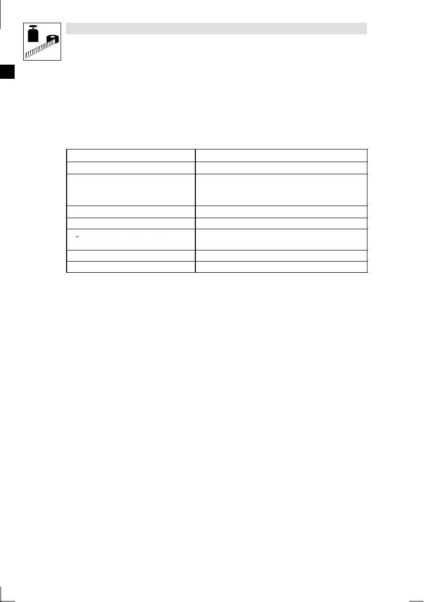
Signalwort Bedeutung
Gefahr! Unmittelbar drohende Gefahr
Warnung! Mögliche, sehr gefährliche Si-
Vorsicht! Mögliche, gefährliche Situation
Stop! Mögliche Sachschäden Beschädigung des Antriebs-
Hinweis! Nützlicher Hinweis oder Tipp
für Personen
tuation für Personen
für Personen
Wenn Sie ihn befolgen, erleichtern
Sie sich die Handhabung des Antriebssystems.
Folgen bei Mißachtung
der Sicherheitshinweise
Tod oder schwerste Verletzungen
Tod oder schwerste Verletzungen
Leichte Verletzungen
systems oder seiner Umgebung
L
7EDBEPM-H510 DE/EN/FR 4.0
Page 8
Technische Daten
ZulässigeTemperaturbereiche
AngewandteNormenzuGrenzwerten
Show/Hide Bookmarks
2 Technische Daten
2.1 Allgemeine Daten/Einsatzbedingungen
Bereich Werte
Schutzart
Zulässige Temperaturbereiche
Feuchtebeanspruchung
Gewicht 1.3 kg
Angewandte Normen zu Grenzwerten
Approbationen cULus: Underwriter Laboratories Inc. (File-No. E189179)
Konformität CE: EMV-Richtlinie (89/336/EEC)
IP65 (Frontseite)
im Betrieb: 0 ... +50 °C
Transport: -20 ... +60 °C
Lagerung: -20 ... +60 °C
<85 %, keine Betauung
Störaussendung nach EN 50081-2 (1994)
Störfestigkeit nach EN 50082-2 (1995)
8
EDBEPM-H510 DE/EN/FR 4.0
L
Page 9
2.2 Elektrische Daten
Display
ElektrischerA
n
Systembus(CAN
)
Speiche
r
Schnittstelle
n
Show/Hide Bookmarks
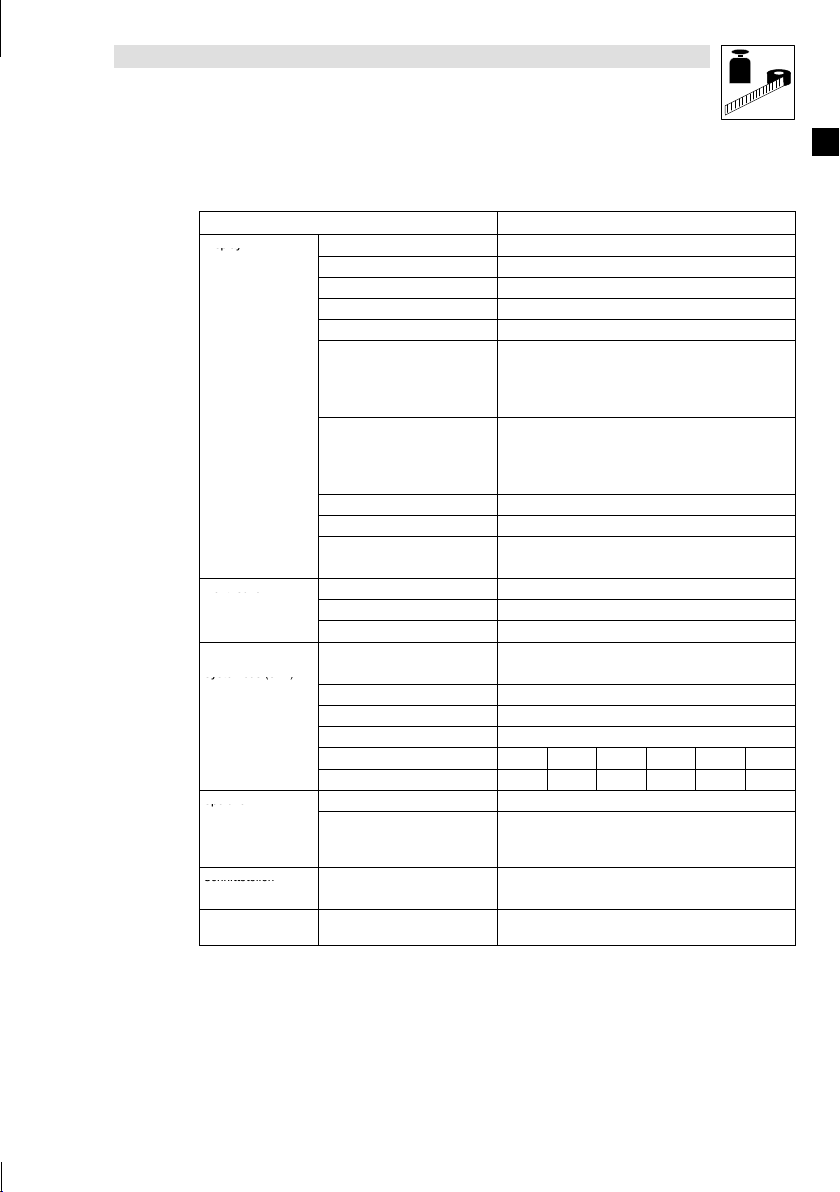
Bereich Werte
Display
Elektrischer Anschluß
Netzwerk:
Systembus (CAN)
Speicher
Schnittstellen
Batterie Sicherung interner Daten und
Typ LCD Monochrom STN, 5.5 “
Darstellungsformat grafisch
Touch screen Matrix 20 × 8 (je 12 × 16 Pixel)
Auflösung 240 x 128 Pixel
Sichtbare Größe 120 × 64 mm
Zeilen × Zeichen
Zeichengröße
Fonts programmierbar
Kontrasteinstellung über Touch screen
Hintergrundbeleuchtung CCFL-Röhre
Lebensdauer bei 25 °C 15000 h
DC-Spannungsversorgung +18 ... 32 VDC
Leistungsaufnahme 15 W bei 24 VDC
Absicherung Feinsicherung ∅5 × 20 mm, 800 mA / F
Protokoll Lenze Systembus (CAN)
Netzwerk-Topologie Linie (beidseitig abgeschlossen mit 120 Ω)
Systembus-Teilnehmer Master oder Slave
max. Anzahl Teilnehmer 63
Baudrate [kBit/s] 20 50 125 250 500 1000
max. Buslänge [m] 2500 1000 500 250 80 25
Anwenderprogramm 512 kB
Datenspeicher
(energieabhäng, nur mit interner
Pufferbatterie verwendbar)
seriell
Echtzeituhr mit Datum
Technische Daten
1-fache Größe
2-fache Größe
4-fache Größe
1-fache Größe
2-fache Größe
4-fache Größe
MSP (DB25 Buchse) RS232
16 × 40
8×20
4×10
3 × 4 mm, Text: 6 × 8 Pixel
6×8mm,Text:12×16Pixel
12 × 16 mm, Text: 24 × 32 Pixel
128 kB
Lithium-Batterie 3 V, ∅19 mm
L
9EDBEPM-H510 DE/EN/FR 4.0
Page 10
Technische Daten
[
A
/
2
)
/
[
k
t
]
Befehle
[Funktion]vorhanden
Show/Hide Bookmarks
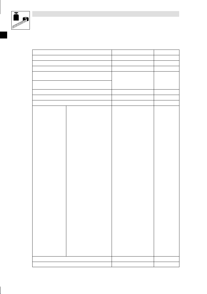
2.2.1 Eigenschaften der Bedieneinheit
Alarm-Hilfe [Anzahl] 1024
Alarme (Insgesamt/Gleichzeitg aktiv) [Anzahl] 1024/256
Alarmfeld [Funktion] vorhanden
Alarmpuffer [Anzahl] 256
Auf Befehl abgetastete Trends (Speicher/Trends/Erfassun-
gen)
Automatisch abgetastete Trends (Speicher/Trends/Erfassun-
gen)
Automatische Operationen [Anzahl] 32
Backup/Wiederherstellen [Funktion] vorhanden
Balkengrafik [Funktion] vorhanden
Alarmregister drucken
Anzeigen Alarmregister
Bedienseite
Blattvorschub auf dem Drucker
Die generelle Seitennummer auf
Null setzen
Hardcopy
Hilfe der Seite
Nächste Seite
Passwort ändern
Passwort Login
Passwort Logout
Projekt beenden
Projektinformationen anzeigen
Befehle
Bit-Paßwort [Bit] 8
Bitmap-Bildverzeichnis [Funktion] vorhanden
Report
Rezept an das Gerä t senden
Rezept aus Datenspeicher laden
Rezept im Datenspeicher sichern
Rezept löschen
Rezept vom Videopuffer an das
Gerät senden
Rezept-Verzeichnis anzeigen
Seiten-Verzeichnis anzeigen
Sprache ändern
Trendpuffer leeren
Vom Gerät empfangenes Rezept
im Datenspeicher sichern
Vom Gerät empfangenes Rezept
im Puffer sichern
Vorangehende Seite
nzahl] 512 byte
Fun
ion
vorhanden
40
10 EDBEPM-H510 DE/EN/FR 4.0
L
Page 11

Technische Daten
k
tbef
DirektbefehlmitWert
-
[
k
t
k
t
[
k
t
]
Funktio
n
[Funktion]vorhanden
Show/Hide Bookmarks
Bogen [Funktion] vorhanden
Datenfeld [Funktion] vorhanden
Der Rezeptstruktur zugeordnete System-Variablen [Funktion] vorhanden
ABZIEHEN
EINGEBEN
Dire
ehl mitWert-
Struktur
Druck [Funktion] vorhanden
Druckseiten (Total/Felder pro Seite) [Anzahl] 1024/128
Dynamische Bitmaps (mit Bitgruppen-Struktur, Einzelbit-
Struktur oder Wert-Struktur)
Dynamische Texte (mit Bitgruppen-Struktur, Einzelbit-Struk-
turoderWert-Struktur)
Etiketten [Funktion] vorhanden
Feld Uhr mit Sekunden [Funktion] vorhanden
Feld Uhr ohne Sekunden [Funktion] vorhanden
Fun
ion
Gleichungen [Anzahl] 32
Informationsmeldungen [insgesamt/gleichzeitig aktiv] 1024/256
Interne Register [Anzahl] 4096 byte
Kopf-/Fußzeilen [Total/Felder pro Kopf-/Fuß-
Kreise [Funktion] vorhanden
Linien [Funktion] vorhanden
Meldungens-Hilfen [Anzahl] 1024
ODER
UND
XOR
ZUFÜGEN
Anzeigen der Seiten-Hilfe
Anzeige der Statusseite des Trei-
bers
Bit permanent setzen
Bit permanent zurücksetzen
Bitumkehr
Direktbefehl mit Wert-Struktur
Echtzeitbit setzen
Echtzeitbit zurücksetzen
Gehe zu Seite
Im Gerät gespeicherte Trends le-
sen
Interner Befehl
Lesen der automatisch abgeta-
steten Trends neu starten
Lesen der automatisch abgeta-
steten Trends stoppen
Makro
Fun
ion] vorhanden
[Anzahl] 1024
[Anzahl] 1024
Fun
ion
zeile]
vorhanden
128/128
1)
1)
L
11EDBEPM-H510 DE/EN/FR 4.0
Page 12
Technische Daten
V
[
A
Variablen
[AnzahljeSeite]96
Show/Hide Bookmarks
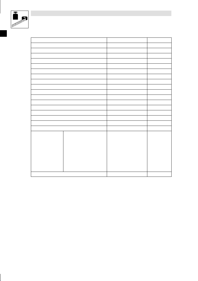
Meldungsfeld [Funktion] vorhanden
Multilinguale Texte [Anzahl Sprachen] 8
Paßwort - Ebenen [Anzahl] 10
Programmierbare Fonts [Funktion] vorhanden
Projektbilder [Funktion] vorhanden
Rechtecke [Funktion] vorhanden
Reporte [Anzahl] 128
Rezepte [Anzahl/Variablen pro Rezept] 1024/256
Rezeptfeld für Rezeptstruktur [Funktion] vorhanden
Schaltflächen [Anzahl je Seite] 160
Seiten [Anzahl] 1024
Seiten-Hilfe [Anzahl] 1024
Statische Bitmaps [Funktion] vorhanden
Systemmeldungen [Funktion] vorhanden
Textlisten [Funktion] vorhanden
Timer [Anzahl] 32
Trendpuffer [Anzahl] 128
Trends (Trends × Seiten/Kanäle × Trends) [Anzahl] 4/4
Grenzwerte- und lineare Korrektur-Variablen
Bewegungsvariablen (bewegliches symbolisches Feld)
ariablen
Wochentagsfeld [Funktion] vorhanden
1)
von der Projektgröße begrenzter Richtwert
2)
von der Speichergrößebegrenzt
Schwellenvariablen
Numerische Gleitpunkt-Variablen
Numerische Variablen (DEC, HEX,
BIN, BCD)
String-Variablen (ASCII)
nzahljeSeite] 96
12 EDBEPM-H510 DE/EN/FR 4.0
L
Page 13

2.2.2 Schnittstellenbeschreibung
Show/Hide Bookmarks
Technische Daten
14
1
Pin Signal
1 N.C.
2 Tx RS232 OUT
3 Rx RS232 IN
4 RTS RS232 OUT
5 CTS RS232 IN
6 N.C.
7 Signal GND
8 N.C.
9 ... 16 Signale werden nicht ausgewertet
17 N.C.
18 Signal wird nicht ausgewertet
19 ... 21 N.C.
22 ... 25 Signale werden nicht ausgewertet
N.C. Nicht angeschlossen
MSP
DB25 Buchse
L
13EDBEPM-H510 DE/EN/FR 4.0
Page 14

Technische Daten
Show/Hide Bookmarks
2.3 Abmessungen
b
Abb. 2-1 Abmessungen
a [mm]
210,0 158,0 36,0 6,0 54,0 86,0
b [mm] c [mm] d [mm] e [mm] f [mm]
2.4 Einbauausschnitt
a
a
c
f
c
d
e
h510_001
b
Abb. 2-2 Einbauausschnitt
a [mm]
198,0 148,0
14 EDBEPM-H510 DE/EN/FR 4.0
h510_002
b [mm]
L
Page 15

3 Installation
Show/Hide Bookmarks
3.1 Mechanische Installation
Installation
Die Maße für den Einbauausschnitt entnehmen Sie den technischen Daten.
1. Bedieneinheit
Einbauausschnitt schieben.
2. Befestigungsschellen(in die Öffnungsschlitze der Bedieneinheit schieben.
&
mit Dichtung'in den
1
0
2
3. Schrauben)gegen die Einbautafel drehen
und fest ziehen.
(% 14)
h510_003
2
h510_007
L
3
EDBEPM-H510 DE/EN/FR 4.0
3
h510_009
15
Page 16
Installation
Show/Hide Bookmarks
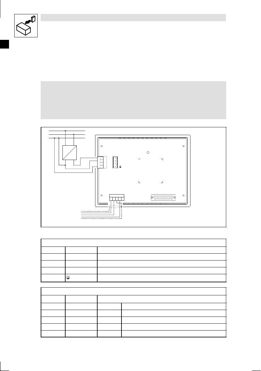
3.2 Elektrische Installation
3.2.1 Belegung der Anschlußklemmen
#
#
##
L1
N
PE
Stop!
!
Beschädigung angeschlossener Geräte. Verbinden Sie den PE-Leiter so wie es
in der Abbildung dargestellt ist!
!
Bedieneinheit nur im spannungslosen Zustand verdrahten!
INPUT VOLTAGE:18-32 VDC 15 W
FUSE 800 mA
1
2
3
4
3 V LITHIUMCELL TYPE CR2032
1
+24 VDC
2
0 VDC
3
N. C.
4
Shield
N.C.
CAN+
V-
CAN-
1234 5
~
–
+18...32VDC
LCD brightness adj.
MSP
Abb. 3-1 Belegung der Anschlußklemmen
DC-Spannungsversorgung
Klemme Bezeichnung Erläuterung
1 +24 VDC Versorgungsspannung (+18 V ... 32 VDC)
2 0VDC GND Versorgungsspannung, Bezugspotential
3 N.C. Nicht angeschlossen
4 PE-Potential
Systembus (CAN)
Klemme Bezeichnung Erläuterung
1 V- GND Bezugspotential
2 CAN- LO Systembus LOW (Datenleitung)
3 Shield Schirm des Systembus-Kabels auflegen
4 CAN+ HI Systembus HIGH (Datenleitung)
5 N.C. Nicht angeschlossen
16
CAN-GND
CAN-LO
CAN-HI
EDBEPM-H510 DE/EN/FR 4.0
h510_004
L
Page 17
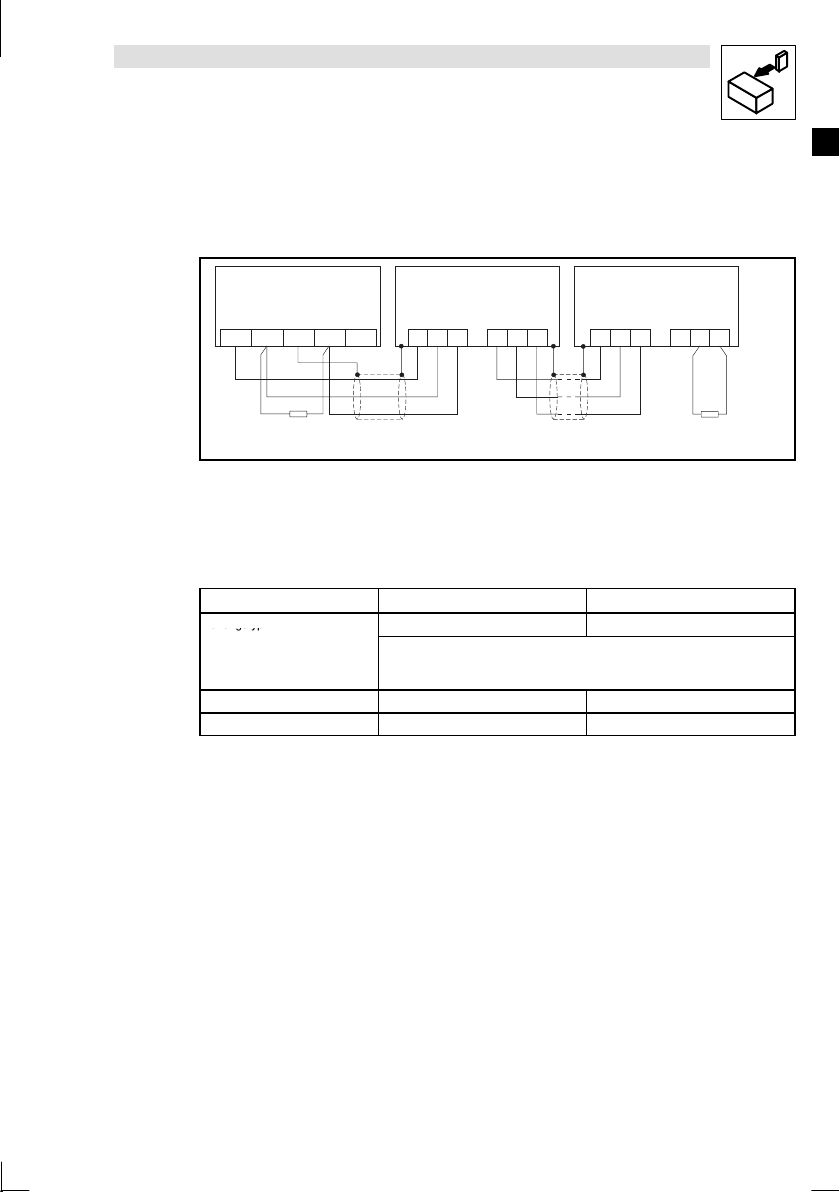
3.2.2 Verdrahtung des Systembus (CAN)
etugsty
p
Show/Hide Bookmarks
Prinzipieller Aufbau
Installation
A
(H510)
1
ShieldCAN--V CAN+ N.C.
120 120
Abb. 3-2 Verdrahtung des Systembus (CAN)
A
Busteilnehmer 1 A2Busteilnehmer 2 AnBusteilnehmer n
1
!
Verbinden Sie nur Klemmen gleichen Signaltyps miteinander.
!
Eigenschaften Signalleitung:
Leitungslänge gesamt bis 300 m 300 bis 1000 m
Leitungstyp LIYCY2x2x0,5mm
Leitungswiderstand ≤40 Ω/km ≤40 Ω/km
Kapazitätsbelag ≤130 nF/km ≤60 nF/km
!
Anschluß der Busabschlußwiderstände:
!
Je ein Widerstand 120 Ω am 1. und am letzen Busteilnehmer
Eigenschaften:
!
Busausdehnung:
– 25 m bei max. 1 Mbit/s Datenübertragungsrate
– bis zu 1 km bei vermindeter Datenübertragungsgeschwindigkeit
!
Sehr zuverlässige Datenübertragung (Hamming-Distanz = 6)
!
Signalpegel nach ISO 11898
!
Bis zu 63 Busteilnehmer möglich
A
2
CG LO HI
paarverseilt mit Abschirmung
Paar 1: CAN-LOW (LO) und CAN-HIGH (HI)
Paar 2: 2 × GND
CG LO HI
2
A
n
CG LO HI CG LO
CYPIMF2x2x0,5mm
HI
h510_006
2
L
EDBEPM-H510 DE/EN/FR 4.0
17
Page 18

Inbetriebnahme
Show/Hide Bookmarks
4 Inbetriebnahme
4.1 Erstes Einschalten
Für die Inbetriebnahme ist eine vollständige Verdrahtung des Systembus notwendig.
#
#
##
Stop!
Überprüfen Sie vor dem Einschalten der Versorgungsspannung
!
die gesamte Verdrahtung auf Vollständigkeit und Kurzschluß,
!
ob das Bussystem beim physikalisch ersten und letzten Busteilnehmer
abgeschlossen ist.
18 EDBEPM-H510 DE/EN/FR 4.0
L
Page 19

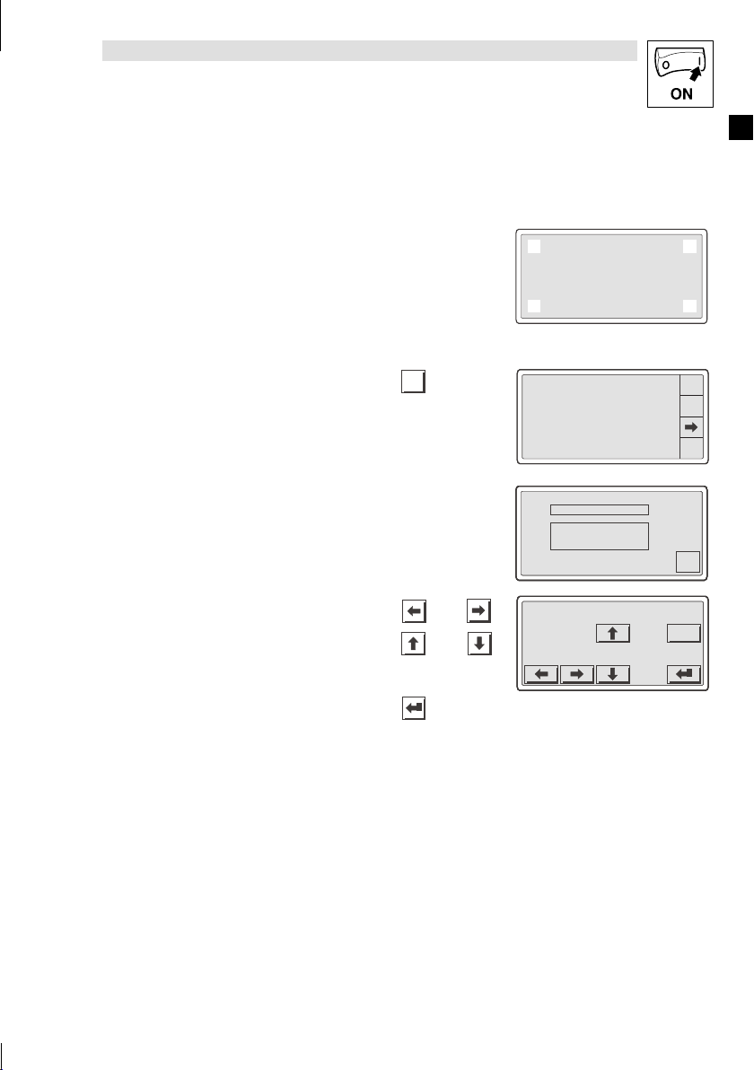
4.1.1 Touch screen kalibrieren
Show/Hide Bookmarks
!
Es kann vorkommen, daß Sie beim ersten Einschalten aufgefordert werden, das
Touch screen Display zu kalibrieren.
!
Mit der Kalibrierung definieren Sie die genauen Positionen der sensitiven Felder auf dem
Display.
$
$ Hinweis!
$$
!
Kalibrieren Sie das Display sorgfältig.
!
Wenn Sie die Kalibrierung falsch oder ungenau durchgeführt haben, schalten
Sie die Bedieneinheit aus und wieder ein, und wiederholen Sie den Vorgang
erneut.
Das müssen Sie tun
Versorgungsspannung für Bedieneinheit einschal-
1.
ten.
Das Gerät wird initialisiert.
2. Berühren Sie genau das Feld&.
Berühren Sie genau das Feld'.
3.
Inbetriebnahme
H510 TRANSFER PAGE
H510 TRANSFER PAGE
H510 TRANSFER PAGE
Graphic controller BOOT check:
Graphic controller BOOT check:
Graphic controller BOOT check:
Please touch bottom left
Please touch bottom left
Please touch bottom left
0
0
0
H510 TRANSFER PAGE
Graphic controller BOOT check:
Please touch top right
1
L
Die Kalibrierung ist abgeschlossen.
DieTransferPageerscheint.
H510 TRANSFER PAGE
Graphic controller BOOT check:
Please wait
Port : NET
Driver : CAN Lenze M
Ver : 1.06
Addr : NO ADDRESS
Error : RESET
PROG
TRAN
PAGE
ESC
19EDBEPM-H510 DE/EN/FR 4.0
Page 20

Inbetriebnahme
Show/Hide Bookmarks
4.2 Projekt in die Bedieneinheit übertragen
4.2.1 Bedieneinheit und PC verbinden
#
# Stop!
##
Die Verbindung zwischen PC und Bedieneinheit nur bei ausgeschalteten Geräten
herstellen!
INPUT VOLTAGE:18-32 VDC 15 W
FUSE 800 mA
1
2
3
4
3 V LITHIUMCELL TYPE CR2032
1
+24 VDC
2
0 VDC
3
N. C.
4
LCD brightness adj.
Shield
CAN+
V-
CAN-
1234 5
l
HMI Designer
Abb. 4-1 Bedieneinheit und PC v erbinden
!
Downloadkabel EPZ-H110 & an der Bedieneinheit auf MSP-Schnittstelle und am PC auf COM1
oder COMx ' stecken.
20 EDBEPM-H510 DE/EN/FR 4.0
1
N.C.
MSP
0
h510_005
L
Page 21

4.2.2 Projekt downloaden
4
.
Show/Hide Bookmarks
Im HMI Designer können Sie auswählen, ob mit dem Laden des Projekts gleichzeitig die Firmware aktualisiert werden soll.
!
Aktualisieren Sie die Firmware immer:
– Beim ersten Download eines Projekts in die Bedieneinheit.
– Nach einem Update des Projektierungstool “HMI Designer”.
!
Klicken Sie dazu im “HMI Designer” im Menü “Downloader” die Option “Firmware” an.
!
Die Firmware wird jedoch immer automatisch aktualisiert, wenn Sie einem Projekt in der
Bedieneinheit einen anderen Treiber zuweisen.
!
Bedenken Sie, daß beim Aktualisieren der Firmware der Download erheblich länger dauert.
Das müssen Sie tun
1. PC einschalten und Projektierungstool HMI De-
signer starten.
Versorgungsspannung für Bedieneinheit ein-
2.
schalten.
Das Gerät wird initialisiert.
Systemseite anwählen. Vorgehensweise:
3.
•
Das Display in den Ecken oben rechts
und unten links'oder
•
oben links(und unten rechts)berühren.
Die erste zu berührende Ecke darf kein anwählbares Feld s ein.
Die Systemseite erscheint.
Das Feld “TRAN PAGE”*berühren.
4.
DieTransferPageerscheint.
Wenn “WAITING FOR DOWNLOAD“ angezeigt wird, ist die Bedieneinheit bereit für
den Datenempfang vom PC.
Gewünschtes Projekt vom HMI Designer in die
5.
Bedieneinheit übertragen.
+ “HMI Designer - Erste Schritte”
Während des Download wird “PROGRAMMING MODE” angezeigt.
6. Nach dem Download ist die Bedieneinheit betriebsbereit und kann über den Systembus mit den ange-
schlossenen Teilnehmern Daten austauschen.
Inbetriebnahme
2
2
2
2
2
2
2
2
2
&
1
1
1
1
1
1
1
1
1
Port : NET
Port : NET
Port : NET
Port : NET
Port : NET
Port : NET
Port : NET
Port : NET
Port : NET
Driver : CAN Lenze M
Driver : CAN Lenze M
Driver : CAN Lenze M
Driver : CAN Lenze M
Driver : CAN Lenze M
Driver : CAN Lenze M
Driver : CAN Lenze M
Driver : CAN Lenze M
Driver : CAN Lenze M
Ver : 1.06
Ver : 1.06
Ver : 1.06
Ver : 1.06
Ver : 1.06
Ver : 1.06
Ver : 1.06
Ver : 1.06
Ver : 1.06
Addr : NO ADDRESS
Addr : NO ADDRESS
Addr : NO ADDRESS
Addr : NO ADDRESS
Addr : NO ADDRESS
Addr : NO ADDRESS
Addr : NO ADDRESS
Addr : NO ADDRESS
Addr : NO ADDRESS
Error : RESET
Error : RESET
Error : RESET
Error : RESET
Error : RESET
Error : RESET
Error : RESET
Error : RESET
Error : RESET
H510 TRANSFER PAGE
H510 TRANSFER PAGE
H510 TRANSFER PAGE
H510 TRANSFER PAGE
H510 TRANSFER PAGE
H510 TRANSFER PAGE
H510 TRANSFER PAGE
H510 TRANSFER PAGE
H510 TRANSFER PAGE
Graphic controller BOOT check: OK
Graphic controller BOOT check: OK
Graphic controller BOOT check: OK
Graphic controller BOOT check: OK
Graphic controller BOOT check: OK
Graphic controller BOOT check: OK
Graphic controller BOOT check: OK
Graphic controller BOOT check: OK
Graphic controller BOOT check: OK
Graphic controller RAM check : OK
Graphic controller RAM check : OK
Graphic controller RAM check : OK
Graphic controller RAM check : OK
Graphic controller RAM check : OK
Graphic controller RAM check : OK
Graphic controller RAM check : OK
Graphic controller RAM check : OK
Graphic controller RAM check : OK
*** WAITING FOR DOWNLOAD ***
*** WAITING FOR DOWNLOAD ***
*** WAITING FOR DOWNLOAD ***
*** WAITING FOR DOWNLOAD ***
*** WAITING FOR DOWNLOAD ***
*** WAITING FOR DOWNLOAD ***
*** WAITING FOR DOWNLOAD ***
*** WAITING FOR DOWNLOAD ***
*** WAITING FOR DOWNLOAD ***
0
0
0
0
0
0
0
0
0
3
3
3
3
3
3
3
3
3
PROG
PROG
PROG
PROG
PROG
PROG
PROG
PROG
PROG
TRAN
TRAN
TRAN
TRAN
TRAN
TRAN
TRAN
TRAN
TRAN
PAGE
PAGE
PAGE
PAGE
PAGE
PAGE
PAGE
PAGE
PAGE
ESC
ESC
ESC
ESC
ESC
ESC
ESC
ESC
ESC
4
4
4
4
4
4
4
4
4
L
$
$ Hinweis!
$$
!
Beispiel-Projekte für die Bedieneinheit finden Sie im Projektierungstool
“HMI Designer” unter Datei
!
Das Projekt bleibt nach Ausschalten der Versorgungsspannung gespeichert.
,
Öffnen ...
,
Samples.
21EDBEPM-H510 DE/EN/FR 4.0
Page 22

Inbetriebnahme
Show/Hide Bookmarks
4.2.3 Verbindung zum PC entfernen
1. PC ausschalten.
2. Versorgungsspannung für Bedieneinheit abschalten.
3. Downloadkabel EPZ-H110 an der Bedieneinheit und am PC abziehen.
4. Versorgungsspannung für Bedieneinheit einschalten.
Die Bedieneinheit ist betriebsbereit.
4.3 Statusmeldungen der Bedieneinheit
Sie können jederzeit den Status der Bedieneinheit abfragen. Sie erhalten Informationen über:
!
Die Schnittstelle (Port)
!
Den Namen des geladenen Treibers (Driver)
!
Die Version des geladenen Treibers (Ver)
!
Die Netzadresse der Bedieneinheit (Addr VT)
!
Die zuletzt aufgetretene Störung (Error)
Sie möchten ... Berühren Sie die Felder ... Beispiel
A) den Status der Bedieneinheit abfragen.
Dazu die Systemseite anwählen:
•
Das Display in den Ecken oben rechts
und unten links'oder
•
oben links(und unten rechts)berühren.
Die erste zu berührende Ecke darf kein anwählbares Feld s ein.
B)
die Statusanzeige schließen.
&
ESC
2
1
Port : NET
Port : NET
Port : NET
Port : NET
Port : NET
Driver : CAN Lenze M
Driver : CAN Lenze M
Driver : CAN Lenze M
Driver : CAN Lenze M
Driver : CAN Lenze M
Ver : 1.06
Ver : 1.06
Ver : 1.06
Ver : 1.06
Ver : 1.06
Addr : NO ADDRESS
Addr : NO ADDRESS
Addr : NO ADDRESS
Addr : NO ADDRESS
Addr : NO ADDRESS
Error : RESET
Error : RESET
Error : RESET
Error : RESET
Error : RESET
0
3
PROG
PROG
PROG
PROG
PROG
TRAN
TRAN
TRAN
TRAN
TRAN
PAGE
PAGE
PAGE
PAGE
PAGE
ESC
ESC
ESC
ESC
ESC
22 EDBEPM-H510 DE/EN/FR 4.0
L
Page 23
Inbetriebnahme
Show/Hide Bookmarks
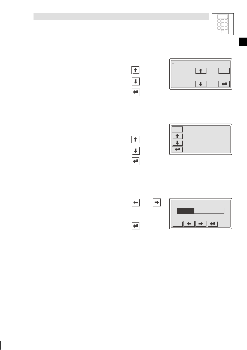
4.4 Datum/Uhrzeit und Kontrast einstellen
Sie möchten ... Berühren Sie die Felder ... Beispiel
A) Datum/Uhrzeit und Kontrast am Display
einstellen.
1. Dazu die Systemseite anwählen:
– Das Display in den Ecken oben
rechts
&
und unten links'oder
(
– oben links
berühren.
Die erste zu berührende Ecke darf kein anwählbares Feld s ein.
2. Menü für Uhrzeit/Datum und Kontrast
anwählen.
und unten rechts
)
PROG
2
1
Port : NET
Port : NET
Driver : CAN Lenze M
Driver : CAN Lenze M
Ver : 1.06
Ver : 1.06
Addr : NO ADDRESS
Addr : NO ADDRESS
Error : RESET
Error : RESET
0
3
PROG
PROG
TRAN
TRAN
PAGE
PAGE
ESC
ESC
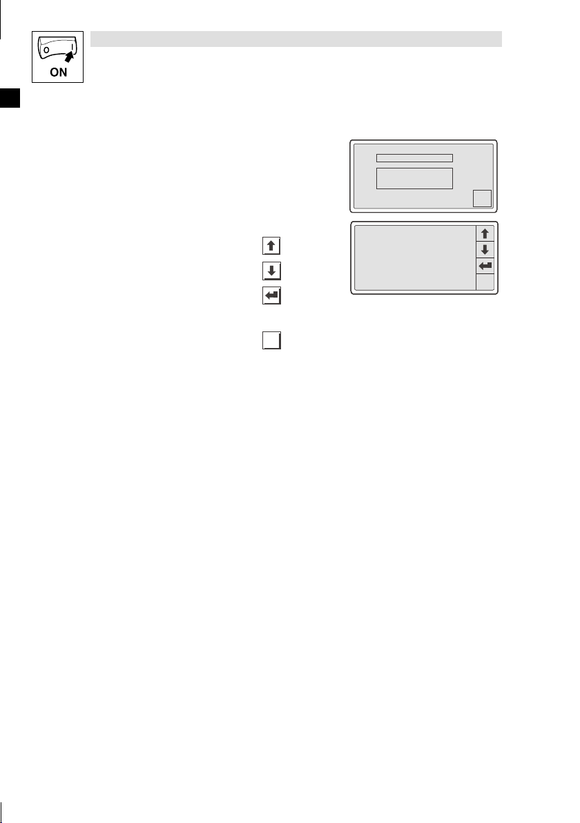
B) Datum/Uhrzeit einstellen.
1. Feld “SET CLOCK” berühren, um das
Menü anzuwählen.
2. Gewünschtes Feld anwählen.
3. Wert ändern.
4. Ggf. Schritt 2. und 3. wiederholen, um
weitere Werte zu ändern.
5. Bestätigen Sie die Eingabe.
– Das Menü für Uhrzeit/Datum und
Kontrast wird angezeigt.
oder
oder
SET CONTRAST : 04
SET CONTRAST : 04
SET CONTRAST : 04
SET CONTRAST : 04
SET CONTRAST : 04
SET CLOCK:
SET CLOCK:
SET CLOCK:
SET CLOCK:
SET CLOCK:
Wed,13/09/00
Wed,13/09/00
Wed,13/09/00
Wed,13/09/00
Wed,13/09/00
12:50:10
12:50:10
12:50:10
12:50:10
12:50:10
12.50.10 13/09/00
12.50.10 13/09/00
12.50.10 13/09/00
12.50.10 13/09/00
ESC
ESC
ESC
ESC
ESC
ESC
ESC
ESC
ESC
L
23EDBEPM-H510 DE/EN/FR 4.0
Page 24
Inbetriebnahme
lassenunddieStatusanzeigeschließe
n
Show/Hide Bookmarks
Sie möchten ... BeispielBerühren Sie die Felder ...
C)
Kontrast am Display einstellen.
1. Feld “SET CONTRAST” berühren, um
das Menü anzuwählen.
2. Kontrast einstellen.
mehr Kontrast
weniger Kontrast
3. Bestätigen Sie die Eingabe.
– Das Menü für Uhrzeit/Datum und
Kontrast wird angezeigt.
Menü Datum/Uhrzeit und Kontrast ver-
D)
lassen und die Statusanzeige schließen.
.
ESC
2x
SET CONTRAST : 04
SET CONTRAST : 04
SET CONTRAST : 04
SET CLOCK:
SET CLOCK:
SET CLOCK:
Wed,13/09/00
Wed,13/09/00
Wed,13/09/00
12:50:10
12:50:10
12:50:10
CONTRAST : 04
CONTRAST : 04
CONTRAST : 04
CONTRAST : 04
ESC
ESC
ESC
ESC
ESC
ESC
ESC
24 EDBEPM-H510 DE/EN/FR 4.0
L
Page 25
5 Bedienung
V
•
VorherigendynamischenTextanwählen
•
NächstendynamischenTextanwählen
Show/Hide Bookmarks
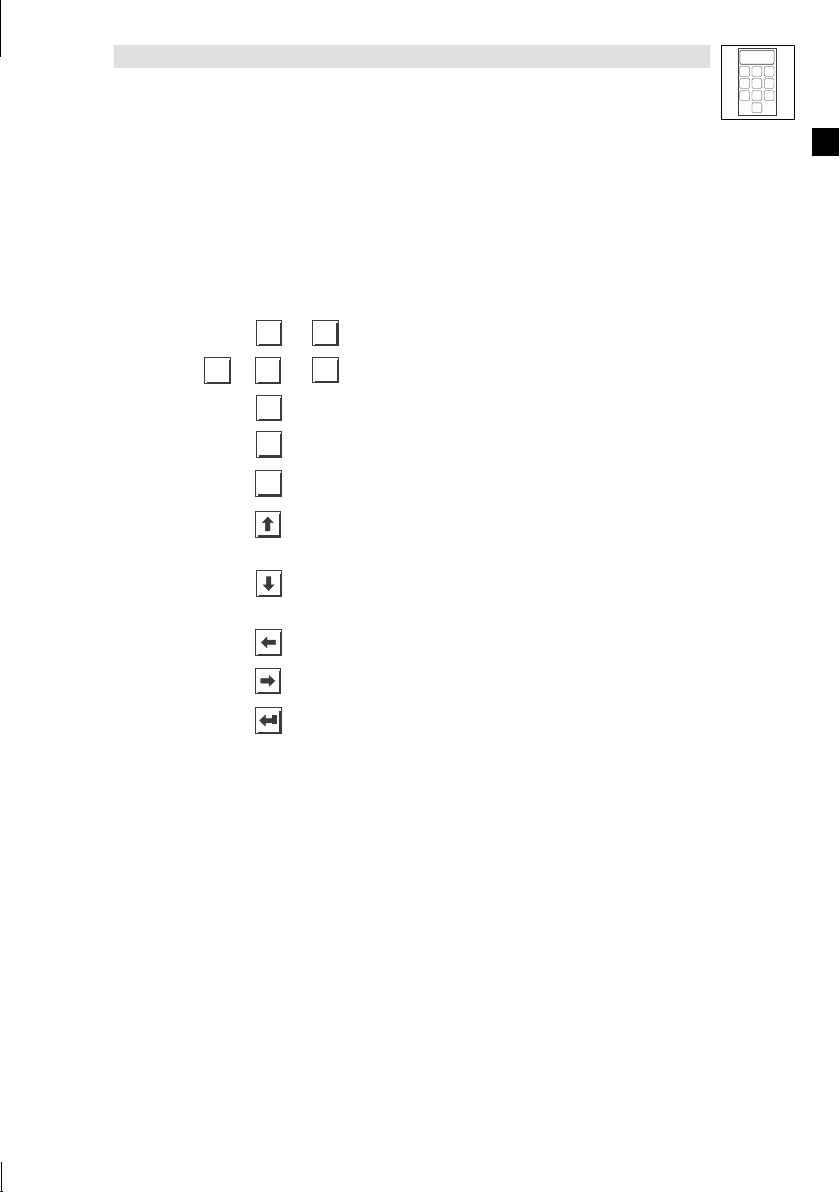
5.1 Tastenfunktionen
Tasten Funktion Erläuterung
9
0
...
<0> ... <9> Numerische Tasten für die Dateneingabe
SHIFT
+
1/A
+/-
ESC
6/F
...
<1/A> ... <6/F>
<+/-> Vorzeichen eingeben
.
<·> Gleitkomma eingeben
<ESC>
<Pfeil auf>
<Pfeil ab>
<Pfeil links>
<Pfeil rechts>
<Enter> Eingegebenen Wert übernehmen
1
Bedienung
Alphanumerische Tasten für die hexadezimale Dateneingabe
Parametereingabe abbrechen; Hilfe-, Informations-,
Alarm- und Statusmeldungen verlassen
2
5
4
7
8
0
Parameter-Ebene:
•
orherigen dynamischen Textanwählen
•
Vorheriges alphanumerisches Zeichen anwählen
Parameter-Ebene:
•
Nächsten dynamischen Textanwählen
•
Nächstes alphanumerisches Zeichen anwählen
Parameter-Ebene: Cursor auf das vorherige Zeichen
stellen
Parameter-Ebene: Cursor auf das nächste Zeichen
stellen
3
6
9
L
25EDBEPM-H510 DE/EN/FR 4.0
Page 26

3
–
DerC
lltsichaufdi
h
t
–
ein
.
Show/Hide Bookmarks
1
2
5
4
7
8
0
6
9
Bedienung
5.2 Daten eingeben
Das Eingebenoder Ändernvon Datenist Schrittfür Schrittdargestellt und wird aneinem Beispielerläutert.
Sie möchten ... Berühren Sie die Felder ... Beispiel
A) ein Menü/eine Seite anwählen.
•
Berühren Sie das gewünschte Feld.
in die Parameter-Ebene wechseln.
B)
•
Berühren Sie das Parameterfeld.
ursor ste
Ziffer.
In einem alphanumerischen oder dy-
namischen Textfeld stellt sich der
Cursor auf das linke Zeichen (siehe J) oder I)).
erec
e
-9876
-9876
-9876
-9876
+/-
+/-
+/-
+/-
ESC
ESC
ESC
ESC
3
3
3
0
0
0
0
1
1
1
1
.
.
.
.
4
4
4
4
7
7
7
7
3
2
2
2
2
5
5
5
5
6
6
6
6
8
9
8
9
8
9
8
9
C) einen numerischen Wert vollständig neu
eingeben.
1. Wechseln Sie in die Parameter-Ebene
(siehe B)).
2. Lassen Sie den Cursor auf der rechten
Ziffer stehen.
3. Geben Sie den Wert der ersten Stelle
ein.
– Alle anderen Stellen werden auf Null
gesetzt.
4. Geben Sie den Wert der nächsten Stelle
ein.
– Die eingegebenen Ziffern werden eine
Stelle nach links geschoben.
5. Geben Sie ggf. ein Gleikomma ein.
TIP Sie können ein Gleitkomma nur einfügen,
wenn das Feld als “Floating Point” definiert
ist (siehe Projektierungstool “HMI Designer”).
6. Wiederholen Sie Schritt 4. bis Sie den
Wert vollständig eingegeben haben.
-9876
ESC
0
1
.
4
7
+/-
0001
0001
0001
0001
0
0
.
9
...
0
0
0
0
1
1
1
1
.
.
.
.
4
4
4
4
7
7
7
7
+/-
+/-
+/-
+/-
0012
0012
0012
0012
0012
9
...
0
0
0
0
0
1
1
1
1
1
.
.
.
.
.
4
4
4
4
4
7
7
7
7
7
+/-
+/-
+/-
+/-
+/-
012.
012.
0
0
1
1
.
.
4
4
7
7
+/-
+/-
3
2
5
6
8
9
ESC
ESC
ESC
ESC
3
3
3
3
2
2
2
2
5
5
5
5
6
6
6
6
8
8
8
8
9
9
9
9
ESC
ESC
ESC
ESC
ESC
3
3
3
3
3
2
2
2
2
2
5
5
5
5
5
6
6
6
6
6
8
9
8
9
8
9
8
9
8
9
ESC
ESC
3
3
2
2
5
5
6
6
8
8
9
9
26 EDBEPM-H510 DE/EN/FR 4.0
L
Page 27

Sie möchten ... BeispielBerühren Sie die Felder ...
Show/Hide Bookmarks
7. Geben Sie ggf. ein Vorzeichen ein.
+/-
8. Bestätigen Sie die Eingabe.
– Der Cursor wechselt in die Menü-
Ebene.
D) eine einzelne numerische Ziffer ändern.
1. Wechseln Sie in die Parameter-Ebene
(siehe B)).
2. Wählen Sie die gewünschte Ziffer.
3. Ändern Sie die Ziffer.
0
...
4. Bestätigen Sie die Eingabe.
– Der Cursor wechselt in die Menü-
Ebene.
E) einen hexadezimalen Wert vollständig
neu eingeben.
1. Wechseln Sie in die Parameter-Ebene
(siehe B)).
2. Lassen Sie den Cursor auf der rechten
Ziffer stehen.
9
Bedienung
12.34
12.34
12.34
0
0
0
1
1
1
.
.
.
4
4
4
7
7
7
+/-
+/-
+/-
12. 49
12. 49
12. 49
0
0
0
1
1
1
.
.
.
4
4
4
7
7
7
+/-
+/-
+/-
1A3F
0
1/A
2/B
4/D
5/E
SHIFT
7
3
1
2
5
6
4
7
8
9
0
ESC
ESC
ESC
3
3
3
2
2
2
5
5
5
6
6
6
8
9
8
9
8
9
ESC
ESC
ESC
3
3
3
2
2
2
5
5
5
6
6
6
8
9
8
9
8
9
ESC
3/C
6/F
8
9
L
3. Geben Sie den Wert der ersten Stelle
ein.
– Alle anderen Stellen werden auf Null
gesetzt.
numerischer Wert
alphanumerischer Wert
4. Geben Sie den Wert der nächsten Stelle
ein.
– Die zuvor eingegebenen Ziffern wer-
den eine Stelle nach links geschoben.
numerischer Wert
alphanumerischer Wert
5. Wiederholen Sie Schritt 4. bis Sie den
Wert vollständig eingegeben haben.
6. Bestätigen Sie die Eingabe.
– Der Cursor wechselt in die Menü-
Ebene.
SHIFT
SHIFT
000B
000B
000B
000B
ESC
ESC
ESC
0
0
0
0
1/A
2/B
1/A
2/B
1/A
2/B
1/A
2/B
4/D
5/E
4/D
5/E
4/D
5/E
4/D
5/E
0
+
1/A
0
+
1/A
9
...
6/F
...
...
6/F
...
SHIFT
SHIFT
SHIFT
SHIFT
7
7
7
7
8
8
8
8
00BD
00BD
00BD
00BD
0
0
0
0
1/A
2/B
1/A
2/B
1/A
2/B
1/A
2/B
4/D
5/E
4/D
5/E
4/D
5/E
4/D
5/E
SHIFT
SHIFT
SHIFT
SHIFT
7
7
7
7
8
8
8
9
8
3/C
3/C
3/C
3/C
6/F
6/F
6/F
6/F
3/C
3/C
3/C
3/C
6/F
6/F
6/F
6/F
ESC
9
9
9
9
ESC
ESC
ESC
ESC
9
9
9
9
27EDBEPM-H510 DE/EN/FR 4.0
Page 28

3
Show/Hide Bookmarks
1
2
5
4
7
8
0
6
9
Bedienung
Sie möchten ... BeispielBerühren Sie die Felder ...
F) eine einzelne hexadezimale Ziffer än-
dern.
1. Wechseln Sie in die Parameter-Ebene
(siehe B)).
2. Wählen Sie die gewünschte Ziffer.
3. Ändern Sie die Ziffer.
numerischer Wert
alphanumerischer Wert
SHIFT
0
...
+
1/A
6/F
...
4. Bestätigen Sie die Eingabe.
– Der Cursor wechselt in die Menü-
Ebene.
G) einen binären Wert vollständig neu ein-
geben.
1. Wechseln Sie in die Parameter-Ebene
(siehe B)).
2. Geben Sie den neuen Wert ein wie in C)
beschrieben.
13FC
13FC
13FC
13FC
13FC
ESC
ESC
ESC
ESC
0
0
0
0
0
1/A
2/B
1/A
2/B
1/A
2/B
1/A
2/B
1/A
2/B
4/D
5/E
4/D
5/E
4/D
5/E
4/D
5/E
4/D
9
SHIFT
SHIFT
SHIFT
SHIFT
SHIFT
0001
0
5/E
7
7
7
7
7
8
8
8
8
8
1
3/C
3/C
3/C
3/C
3/C
6/F
6/F
6/F
6/F
6/F
ESC
9
9
9
9
9
ESC
H) eine einzelne binäre Ziffer ändern.
1. Wechseln Sie in die Parameter-Ebene
(siehe B)).
2. Geben Sie den neuen Wert ein wie in D)
beschrieben.
I) ein dynamisches Textfeld ändern.
1. Wechseln Sie in die Parameter-Ebene
(siehe B)).
J) einen Rezeptnamen ändern.
1. Wechseln Sie in die Parameter-Ebene
(siehe B)).
2. Wählen Sie das gewünschte Zeichen.
3. Ändern Sie das Zeichen über die Tastatur.
4. Wiederholen Sie Schritt 2. und 3. bis der
neue Name eingegeben ist
(z. B “REZEPTUR1”).
5. Bestätigen Sie die Eingabe.
– Der Cursor wechselt in die Menü-
Ebene.
28 EDBEPM-H510 DE/EN/FR 4.0
oder
1101
0
REZEPT1
REZEPT1
REZEPT1
REZEPT1
0
0
0
0
Q
Q
Q
Q
A
A
A
A
Z
Z
Z
Z
SP
SP
SP
SP
ESC
ESC
ESC
ESC
1
5
5
5
1
1
1
1
W
W
W
W
S
S
S
S
X
X
X
X
5
2
2
2
2
3
4
3
4
3
4
3
4
V
V
V
V
E
E
E
E
R
T
R
T
R
T
R
T
D
D
D
D
H
H
H
H
F
F
F
F
G
G
G
G
N
N
N
N
V
V
V
V
B
B
B
B
C
C
C
C
[
]
[
]
[
]
[
~
~
~
~
<
<
<
<
]
‘
‘
‘
‘
:
:
:
:
>
>
>
>
“
“
“
“
ESC
6
7
6
7
6
7
6
7
8
8
8
8
9
9
9
9
U
U
U
U
I
I
I
I
P
P
P
P
O
O
O
O
_
_
_
_
J
J
J
J
K
K
K
K
L
L
L
L
-
-
-
-
=
=
=
=
+
+
+
+
M
M
M
M
{
}
{
}
{
}
{
}
;
;
;
;
/
/
/
/
?
?
?
?
L
Page 29
Sie möchten ... BeispielBerühren Sie die Felder ...
–
–DerCursorwechseltindieMenü
–
–DerCursorwechseltindieMenü
VALzeigtdeneingegebenenWert
DerCursorwechseltindieMen
ü
Show/Hide Bookmarks
6. Ändern Sie den Text.
nächster Text
vorheriger Text
7. Bestätigen Sie die Eingabe.
DerCursorwechseltin die Menü-
Ebene.
-
K) ein Symbol in einem Symbolfeld ändern.
1. Wechseln Sie in die Parameter-Ebene
(siehe B)).
2. Ändern Sie das Symbol.
-,.,/,0
(z. B.
)
nächstes Symbol
vorheriges Symbol
3. Bestätigen Sie die Eingabe.
DerCursorwechseltin die Menü-
Ebene.
L) einen Wert über ein Balkendiagramm
eingeben.
1. Wechseln Sie in die Parameter-Ebene
(siehe B)).
2. Geben Sie den Wert ein.
– “VAL” zeigt den eingegebenen Wert
numerisch an.
-
oder
3. Bestätigen Sie die Eingabe.
– Der Cursor wechselt in die Menü-
Ebene.
Bedienung
ON
ON
ON
ON
[
[
[
[
ESC
ESC
ESC
ESC
VAL:36
VAL:36
VAL:36
ESC
ESC
ESC
3
1
2
5
6
4
7
8
9
0
ESC
ESC
ESC
ESC
MAX:100Min:0
MAX:100Min:0
MAX:100Min:0
L
29EDBEPM-H510 DE/EN/FR 4.0
Page 30
3
Show/Hide Bookmarks
1
2
5
4
7
8
0
6
9
Bedienung
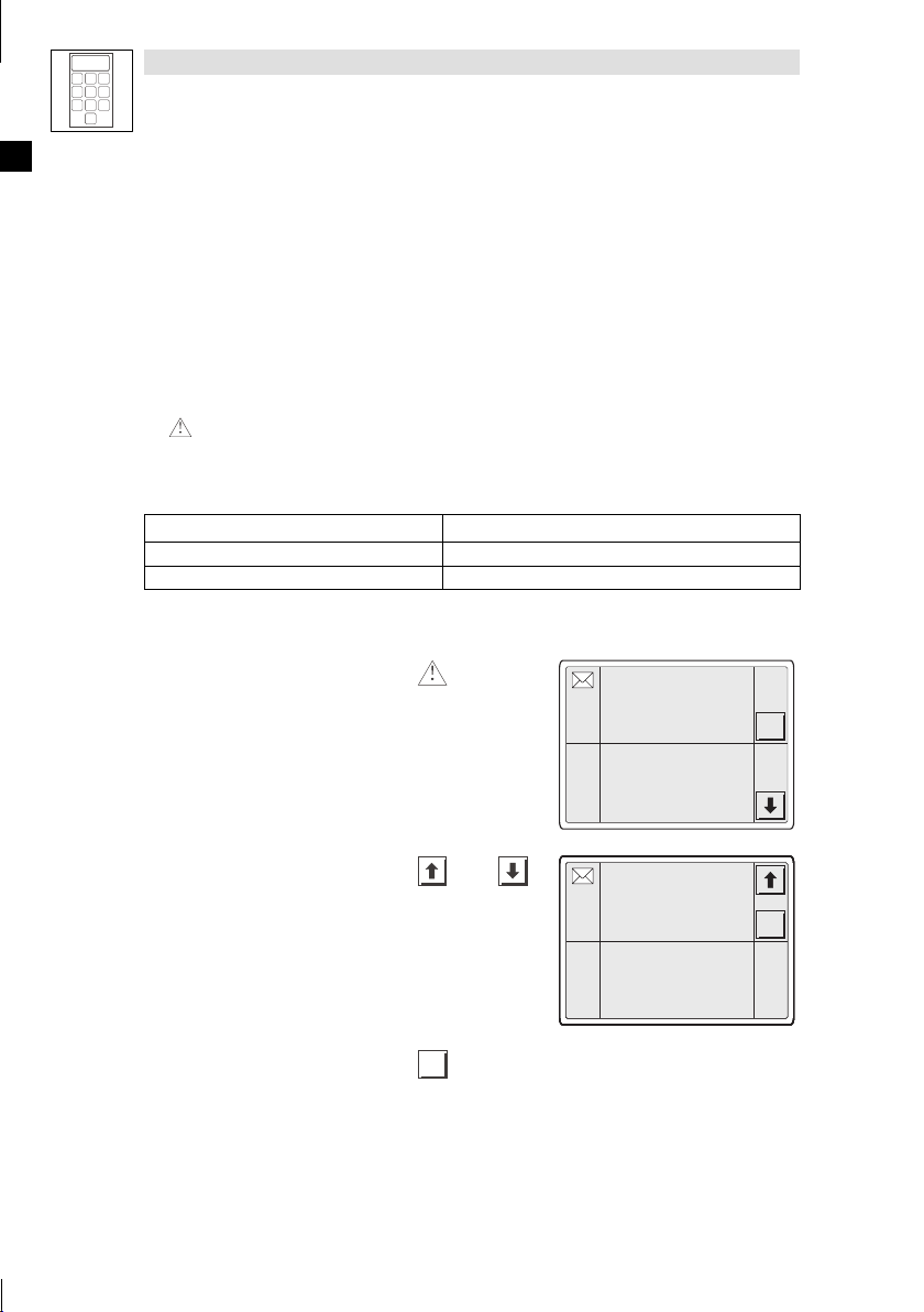
5.3 Informationsmeldung aufrufen
!
Informationsmeldungen
– sind Texte, die aufgrund eines Ereignisses angezeigt werden (z. B., wenn ein Istwert eine
Grenze übersteigt).
– können S ie nur aufrufen, solange das auslösende Ereignis vorhanden ist.
– müssen im Projektierungstool “HMI Designer” programmiert worden sein.
– können max. 5 Zeilen × 30 Zeichen lang sein (einfache Zeichengröße).
!
Die zweitletzte Zeile enthält ein programmierbares Meldungsfeld. Dieses Feld zeigt die
numerische Größe der Variablen, die die Meldung aktiviert hat.
!
Die letzte Zeile zeigt Datum und Uhrzeit, wann die Meldung ausgelöst wurde.
!
signalisiert, wenn eine Informationsmeldung vorhanden ist.
Symbole und Zeichen in den Informationsmeldungen
Symbole/Zeichen in der Zeile Datum/Uhrzeit Bedeutung
"
HELP Der Informationsmeldung ist eine Hilfe zugeordnet. (+ 33)
Sie möchten ... Berühren Sie die Felder ... Beispiel
A) eine Informationsmeldung aufrufen.
•
Eine Seite kann max. 2 Informationsmeldungen anzeigen.
Die Informationsmeldung wurde zum erstenmal aufgerufen
Druck uebersteigt
die Sicherheitsgrenze
125.5
13-09-2000 10:45a HELP
Temperatur uebersteigt
die Sicherheitsgrenze
1700
13-09-2000 10:55a HELP
ESC
B) die nächsten Informationsmeldungen an-
wählen.
C) die Informationsmeldungen schließen.
ESC
30 EDBEPM-H510 DE/EN/FR 4.0
oder
Wasserstand unterhalb
Wasserstand unterhalb
Wasserstand unterhalb
Wasserstand unterhalb
Wasserstand unterhalb
Wasserstand unterhalb
Wasserstand unterhalb
der Grenze
der Grenze
der Grenze
der Grenze
der Grenze
der Grenze
der Grenze
-10
-10
-10
-10
-10
-10
-10
13-09-2000 11:00a HELP
13-09-2000 11:00a HELP
13-09-2000 11:00a HELP
13-09-2000 11:00a HELP
13-09-2000 11:00a HELP
13-09-2000 11:00a HELP
13-09-2000 11:00a HELP
ESC
ESC
ESC
ESC
ESC
ESC
ESC
L
Page 31

5.4 Alarmmeldungen aufrufen
Show/Hide Bookmarks
!
Alarmmeldungen
– sind Texte, die aufgrund eines Ereignisses angezeigt werden (z. B., wenn ein Istwert eine
Grenze übersteigt).
– müssen im Projektierungstool “HMI Designer” programmiert worden sein.
– können max. 5 Zeilen × 30 Zeichen lang sein (einfache Zeichengröße).
– werden in einem Alarmregister chronologisch nach Datum und Uhrzeit gespeichert.
!
Die zweitletzte Zeile enthält ein programmierbares Meldungsfeld. Dieses Feld zeigt die
numerische Größe der Variablen, die die Meldung aktiviert hat.
!
Die letzte Zeile zeigt Datum und Uhrzeit, wann die Meldung ausgelöst wurde.
!
signalisiert, wenn eine Alarmmeldung vorhanden ist.
Symbole und Zeichen in den Alarmmeldungen
Symbole1Zeichen in der Zeile Datum/Uhrzeit Bedeutung
> Nicht quittierter Alarm.
# Quittierter Alarm. jedoch Alarmursache noch vorhanden.
< Nicht quittierter Alarm, jedoch Alarmursache nicht mehr
HELP Der Alarmmeldung ist eine Hilfe zugeordnet. (+ 33)
1)
Wenn eine Alarmmeldung mehrfach eingegangen ist, signalisiert das Symbol die zuletzt eingegangene
Meldung
vorhanden.
Bedienung
3
1
2
5
6
4
7
8
9
0
Sie möchten ... Berühren Sie die Felder ... Beispiel
A) eine Alarmmeldung aufrufen.
B)
L
weitere Alarmmeldungen anwählen.
oder
EDBEPM-H510 DE/EN/FR 4.0
Druck im Tank uebersteigt
die max. Grenze
150.0
>13-09-2000 10:45a HELP
0001
Wasserstand unterhalb der
Schwelle des Prozesses
10
>13-09-2000 10:45a
0032
<13-09-2000 10:55a HELP
Temperatur uebersteigt
Temperatur uebersteigt
Temperatur uebersteigt
Temperatur uebersteigt
Temperatur uebersteigt
Temperatur uebersteigt
Temperatur uebersteigt
die Sicherheitsgrenze
die Sicherheitsgrenze
die Sicherheitsgrenze
die Sicherheitsgrenze
die Sicherheitsgrenze
die Sicherheitsgrenze
die Sicherheitsgrenze
1600
1600
1600
1600
1600
1600
1600
>13-09-2000 12:25p
>13-09-2000 12:25p
>13-09-2000 12:25p
>13-09-2000 12:25p
>13-09-2000 12:25p
>13-09-2000 12:25p
>13-09-2000 12:25p
0006
0006
0006
0006
0006
0006
0006
#13-09-2000 12:30p HELP
#13-09-2000 12:30p HELP
#13-09-2000 12:30p HELP
#13-09-2000 12:30p HELP
#13-09-2000 12:30p HELP
#13-09-2000 12:30p HELP
#13-09-2000 12:30p HELP
ESC
HIST
ESC
ESC
ESC
ESC
ESC
ESC
ESC
HIST
HIST
HIST
HIST
HIST
HIST
HIST
31
Page 32

3
AlarmschronologischnachDatumund
Uhrzeitgespeichert.
Show/Hide Bookmarks
1
2
5
4
7
8
0
6
9
Bedienung
Sie möchten ... BeispielBerühren Sie die Felder ...
das Alarmregister zu einer Alarmmel-
C)
dung anwählen.
•
Im Alarmregister ist das Auftreten des
HIST
Uhrzeit gespeichert.
•
Ein “H” in der linken Spalte signalisiert,
daß einAlarmregister angewähltist.
•
Alarmregister schließen und zur Alarmmeldung zurückkehren.
D) die Alarmmeldungen schließen.
$
$ Hinweis!
$$
!
Wenn der Puffer des Alarmregisters voll ist, werden keine weiteren Alarme
ESC
ESC
gespeichert.
!
Im ”HMI Designer” können Sie Befehlsbereiche definieren, um alle Alarme zu
quittieren oder den Puffer des Alarmregisters zu leeren.
Druck im Tank uebersteigt
Druck im Tank uebersteigt
Druck im Tank uebersteigt
Druck im Tank uebersteigt
Druck im Tank uebersteigt
Druck im Tank uebersteigt
H
H
H
H
H
H
die max. Grenze
die max. Grenze
die max. Grenze
die max. Grenze
die max. Grenze
die max. Grenze
150.0
150.0
150.0
150.0
150.0
150.0
0001
0001
0001
0001
0001
0001
>13-09-2000 10:45a
>13-09-2000 10:45a
>13-09-2000 10:45a
>13-09-2000 10:45a
>13-09-2000 10:45a
>13-09-2000 10:45a
<13-09-2000 10:48a
<13-09-2000 10:48a
<13-09-2000 10:48a
<13-09-2000 10:48a
<13-09-2000 10:48a
<13-09-2000 10:48a
#13-09-2000 10:55a
#13-09-2000 10:55a
#13-09-2000 10:55a
#13-09-2000 10:55a
#13-09-2000 10:55a
#13-09-2000 10:55a
Wasserstand unterhalb der
Wasserstand unterhalb der
Wasserstand unterhalb der
Wasserstand unterhalb der
Wasserstand unterhalb der
Wasserstand unterhalb der
H
H
H
H
H
H
Schwelle des Prozesses
Schwelle des Prozesses
Schwelle des Prozesses
Schwelle des Prozesses
Schwelle des Prozesses
Schwelle des Prozesses
10
10
10
10
10
10
0032
0032
0032
0032
0032
0032
>13-09-2000 10:45a
>13-09-2000 10:45a
>13-09-2000 10:45a
>13-09-2000 10:45a
>13-09-2000 10:45a
>13-09-2000 10:45a
<13-09-2000 10:50a
<13-09-2000 10:50a
<13-09-2000 10:50a
<13-09-2000 10:50a
<13-09-2000 10:50a
<13-09-2000 10:50a
#13-09-2000 10:53a
#13-09-2000 10:53a
#13-09-2000 10:53a
#13-09-2000 10:53a
#13-09-2000 10:53a
#13-09-2000 10:53a
ESC
ESC
ESC
ESC
ESC
ESC
32
EDBEPM-H510 DE/EN/FR 4.0
L
Page 33

Bedienung
Show/Hide Bookmarks
5.5 Hilfe aufrufen
!
Hilfemeldungen
– können S eiten- oder Informationsmeldungen zugeordnet sein,
– enthalten nützliche Hinweise, die die Bedienung erleichtern,
– müssen im Projektierungstool “HMI Designer” programmiert worden sein,
– für Informationsmeldungen können max. 16 Zeilen × 34 Zeichen lang sein (einfache
Zeichengröße),
– für Projektseiten können max. 16 Zeilen × 40 Zeichen lang sein (einfache Zeichengröße).
Sie möchten ... Berühren Sie die Felder ... Beispiel
A) die Hilfe zu einer Informationsmeldung
aufrufen.
1. Berühren Sie das Meldungsfeld, wenn
eine Informationsmeldung mit “HELP”
gekennzeichnet ist.
2. Hilfe schließen.
B) die Hilfe zu einer Seite aufrufen.
1. Berühren Sie das entsprechend programmierte Feld, w enn zu einer Seite
eine Hilfe vorhanden ist.
2. Hilfe schließen.
ESC
ESC
Druck uebersteigt
Druck uebersteigt
die Sicherheitsgrenze
die Sicherheitsgrenze
125.5
125.5
13-09-2000 10:45a HELP
13-09-2000 10:45a HELP
Temperatur uebersteigt
Temperatur uebersteigt
die Sicherheitsgrenze
die Sicherheitsgrenze
1700
1700
13-09-2000 10:55a HELP
13-09-2000 10:55a HELP
3
1
2
5
6
4
7
8
9
0
ESC
ESC
L
33EDBEPM-H510 DE/EN/FR 4.0
Page 34

Fehlersuche und Störungsbeseitigung
K
i
k
Feh
ler
haf
teVerdrah
t
Verdrah
t
rüfen(+17)
g
gp(
)
Systemb
(
Systemb
(CAN)unter-
•
FehlerhafteParametrierung
Schritte)
derSchnittstelle(Baudrate
,
Show/Hide Bookmarks
6 Fehlersuche und Störungsbeseitigung
6.1 Störungsmeldungen
Rufen Sie die Statusmeldungen der Bedieneinheit auf, um die zuletzt aufgetretene Störungsmeldung
anzuzeigen.
(% 22)
Display (ERROR)
NO ERROR Keine Störung - -
PR ERROR Fehlerhafter
COM BROK Kommunika-
A-ASIC ko1
ASIC ko2
ASIC ko3
ASIC ko4
RESET
SDOERR 6
SDOERR 5
SDOERR 3
Störung Ursache Abhilfe
Datenaustausch
tion unterbrochen
ommun
tion mit
CAN)unter-
brochen
Verbindung zwischen Bedieneinheit undPC ist fehlerhaft
Serielles Datenkabel zwischen
Bedieneinheit und PC ist defekt
oder nicht richtig angeschlossen
a-
•
us
(z. B. Verpolung) des
•
der Schnittstelle (Baudrate,
Adresse, Identifier)
ung
us
•
Anschlüsse auf festen Sitz prüfen
•
Leitung auf Beschädigung kontrollieren
•
Sub D-Stecker auf richtigen Anschluß und festen Sitz prüfen
•
Serielles Datenkabel austauschen
•
•
ung p
Parametrierung prüfen (+ siehe
“
Handbuch “HMI Designer”Erste
”
34
EDBEPM-H510 DE/EN/FR 4.0
L
Page 35

7 Wartung
Show/Hide Bookmarks
7.1 Wartungsarbeiten
!
Die Bedieneinheit ist wartungsfrei, wenn die vorgeschriebenen Einsatzbedingungen eingehalten
werden.
(% 8)
!
Reinigen Sie die Bedieneinheit mit denaturiertem Äthylalkohol.
– Wenn Sie ein anderes Reinigungsmittel verwenden müssen, um Verunreinigungen zu
beseitigen, beachten Sie die Angaben in der Tabelle im Kap. 8.1.
7.2 Interne Batterie wechseln
!
Eine geräteinterne Batterie sorgt dafür, daß Rezeptdaten, Systemzeit/Datum und
Kontrasteinstellung der Bedieneinheit bei abgeschalteter Spannungsversorgung erhalten
bleiben.
!
Daten der Batterie:
– Lithium-Batterie 3 V, ∅19 mm (CR2032)
– Bestellnummer: EPZ-H600
#
#
##
Stop!
!
Vor dem Öffnen des Gehäuses Spannungsversorgung abschalten!
!
Um Datenverlust zu vermeiden, müssen Sie innerhalb 30 Minuten nach
Entnahme der leeren Batterie eine neue Batterie einsetzen.
Wartung
(% 37)
Abb. 7-1 Gehäusedeckel abnehmen
L
Gehäusedeckel abnehmen
INPUT VOLTAGE: 18-32 VDC 15 W
FUSE 800 mA
3 V LITHIUM CELL TYPE CR2032
1
1
2
3
4
0
+24 VDC
2
0 VDC
3
N. C.
4
1
Shield
N.C.
CAN+
V-
CAN-
1234 5
1. Klemmleiste
2. Schrauben
'
abziehen
&
lösen und Gehäusedeckel abnehmen
LCD brightness adj.
0
MSP
h510_008
35EDBEPM-H510 DE/EN/FR 4.0
Page 36

Wartung
Show/Hide Bookmarks
Batterie wechseln
1
2
3
4
Abb. 7-2 Batterie wechseln
1. Bügel
2. Bügel anheben und neue Batterie einlegen (Bügel ist Plus-Anschluß)
Gehäusedeckel schließen
(
1
2
3
4
0
2
3
anheben und Batterie)entnehmen
INPUT VOLTAGE: 18-32 VDC 15 W
FUSE 800 mA
3 V LITHIUM CELL TYPE CR2032
1
+24 VDC
2
0 VDC
3
N. C.
4
LCD brightness adj.
1
+
h510_011
0
Shield
V-
CAN-
1234 5
N.C.
CAN+
MSP
Abb. 7-3 Gehäusedeckel schließen
1. Gehäusedeckel aufsetzen, Schrauben
2. Klemmleiste
'
aufstecken
&
eindrehen und festziehen
36 EDBEPM-H510 DE/EN/FR 4.0
h510_008
L
Page 37

8 Anhang
Show/Hide Bookmarks
8.1 Chemikalienbeständigkeit
Die folgende Tabelle zeigt die Beständigkeit der Bedien-Oberfläche (Tastatur, Display, Touch Screen)
gegen die genannten Chemikalien.
Für die Bedieneinheiten EPM-H502 ... EPM-H520 bietet Lenze Schutzfolien an, mit einer verbesserten
Beständigkeit gegen die genannten Chemikalien.
#
#
##
Substanz
Aceton —
Ameisensäure ≥ 50 % — —
Ammoniak ≥ 2% — —
Äthylenglykol
Ätznatron ≥ 2% — —
Benzin
Benzol
Benzylalkohol — —
Beizlösung konzentriert — — —
Dieselöl
Eisessig — —
Essigsäure ≥ 5%<50%
Ethanol
Isopropanol
Methanol
Methylenchlorid — —
Mineralsäuren konzentriert — —
Natriumhydroxid ≥ 50 %
Perchlorethylen — —
Phosphorsäure ≥ 30 %
Stop!
Die Bedien-Oberfläche ist wenig beständig gegen saure Nahrungsmittel (z. B.
Tomatensaft, Zitronensaft). Verschmutzungen deshalb gleich entfernen, sonst kann
die Oberfläche beschädigt werden.
EPM-H310
EPM-H315
Anhang
Bedieneinheit
EPM-H410 EPM-H502, EPM-H505
# # ☺
# # #
☺ # # ☺
☺ ☺ # ☺
☺ ☺ ☺ ☺
# # # ☺
# # # ☺
☺ ☺ # ☺
☺ ☺ #
# # #
# # # #
EPM-H510, EPM-H520
ohne
Schutzfolie
Schutzfolie
# #
# #
# #
# #
# #
# #
# #
# ☺
mit
#
—
—
—
L
37EDBEPM-H510 DE/EN/FR 4.0
Page 38

Anhang
Show/Hide Bookmarks
EPM-H315
Substanz
Salpetersäure ≥5%<10%
Salzsäure ≥ 10 %
Schwefelsäure ≥ 50 %
Tol u ol
Trichlorethylen — —
Unterchlorigsaures Natron ≥ 20 % — —
Wasserstoffsuperoxyd ≥ 25 % — —
Hochdruck und Temperatur
> 100 °C
Oberfläche ist beständig, keine sichtbare Beschädigung
☺
Oberfläche ist nicht beständig, wird beschädigt
#
—
nicht getestet
# # # ☺
# # # #
# # # #
☺ ☺ # ☺
— —
EPM-H410EPM-H310
Bedieneinheit
EPM-H502, EPM-H505
EPM-H510, EPM-H520
Schutzfolie
ohne
Schutzfolie
# ☺
# #
# #
# #
mit
38 EDBEPM-H510 DE/EN/FR 4.0
L
Page 39

8.2 Stichwortverzeichnis
Show/Hide Bookmarks
Anhang
A
Abmessungen, 14
Alarmmeldungen, 31
Allgemeine Daten, 8
Anhang, 37
Anschluß, elektischer, 9
Anschlußklemmen, Belegung, 16
Antriebsregler, 6
B
Baudrate, Systembus (CAN), 9
Bedieneinheit
- Alarmmeldung aufrufen, 31
- Daten eingeben, 26
- Eigenschaften, 10
- Funktion der Tasten, 25
- Hilfe aufrufen, 33
- Informationsmeldung aufrufen, 30
- Projekt in die übertragen, 20
- Schnittstellenbeschreibung, 13
- Statusmeldungen, 22
- Verbindung zum PC entfernen, 22
- Verbindung zum PC herstellen, 20
Bedienung, 25
Begriffsdefinitionen, 6
Display, 9
- Kontrast einstellen, 23
E
Eigenschaften, 10
Einbauausschnitt, 14
Einsatzbedingungen, 8
- Feuchtebeanspruchung, 8
- Schutzart, 8
- zulässige Temperaturbereiche, 8
Einschalten
-erstes,18
- Touch screen kalibrieren, 19
elektrische Daten, 9
Erstes Einschalten, 18
- Touch screen kalibrieren, 19
F
Fehlersuche, 34
- Störungsmeldungen, 34
Feuchtebeanspruchung, 8
G
Gewicht, 8
C
Chemikalienbeständigkeit, 37
D
Daten, eingeben, 26
Datum, einstellen, 23
DC-Spannungsversorgung, 9
L
H
Hilfemeldung, 33
Human Machine Interface, 6
I
Inbetriebnahme, 18
- erstes Einschalten, 18
Informationsmeldungen, 30
39EDBEPM-H510 DE/EN/FR 4.0
Page 40

Anhang
Show/Hide Bookmarks
Installation
- Anschlußklemmen, Belegung, 16
- elektrische, 16
- mechanische, 15
- Systembus (CAN), 17
K
Kontrast, einstellen, 23
L
Leistungsaufnahme, 9
M
Mechanische Installation, 15
P
PC
- Verbindung zur Bedieneinheit entfernen, 22
- Verbindung zur Bedieneinheit herstellen, 20
Projekt
- downloaden, 21
- in die Bedieneinheit übertragen, 20
S
Schutzart, 8
Sicherheitshinweise, 7
Speicher, 9
Statusmeldungen, 22
Störungsbeseitigung, 34
Störungsmeldungen, 34
Systembus (CAN)
- Baudrate, 9
- Verdrahtung, 17
T
Tastenfunktionen, 25
Technische Daten, 8
- Abmessungen, 14
- Allgemeine Daten/Einsatzbedingungen, 8
- DC-Spannungsversorgung, 9
-Display,9
- Einbauausschnitt, 14
- elektrische Daten, 9
- elektrischer Anschluß, 9
-Gewicht,8
- Leistungsaufnahme, 9
- Schnittstellenbeschreibung, 13
- Speicher, 9
- Systembus (CAN), 9
Touch screen, kalibrieren, 19
U
Uhrzeit, einstellen, 23
W
Wartung, 35
- Wartungsarbeiten, 35
Wartungsarbeiten, 35
Z
Zulässige Temperaturbereiche, 8
40 EDBEPM-H510 DE/EN/FR 4.0
L
Page 41

About these Instructions
Show/Hide Bookmarks
This documentation only applies to the EPM-H510 keypad as of version:
EPM-H510 1A 10
Type
Hardware version
Software version
What’s new?
ID-No. Version Changes
00415800 1.0 06/2000 TD23 First edition for field test
00418424 2.0 08/2001 TD23 Complete revision for series production
00457283 3.0 08/2002 TD01 Change of company name
00479658 4.0 01/2004 TD23 Chapter ”Technical data”:
•
Extended list of features
Chapter ”Appendix”:
•
Extended by information about resistance to chemicals
when using protective foils
All chapters:
•
Fault elimination
© 2004 Lenze Drive Systems GmbH, Hameln
No part of these Instructions must be copied or given to third parties without written approval of Lenze Drive Systems GmbH.
All indications given in this documentation have been selected carefully and comply with the hardware and software described.
Nevertheless, deviations cannot be ruled out. We do not take any responsibility or liability for damages which might possibly occur.
Necessary corrections will be included in the next edition.
4.0 01/2004
L
EDBEPM-H510 DE/EN/FR 4.0
41
Page 42

Contents
Show/Hide Bookmarks
1 Preface and general information 44................................
1.1 About these Operating Instructions 44.........................................
1.2 Terminology used 44.....................................................
1.3 Scope of supply 44......................................................
1.4 Layout of the safety instructions 45...........................................
2 Technical data 46.............................................
2.1 General data/application conditions 46........................................
2.2 Electrical data 47.......................................................
2.2.1 Features of the keypad 48.........................................
2.2.2 Interface description 51...........................................
2.3 Dimensions 52.........................................................
2.4 Mounting cut-out 52.....................................................
3 Installation 53................................................
3.1 Mechanical installation 53.................................................
3.2 Electrical installation 54...................................................
3.2.1 Assignment of the connection terminals 54.............................
3.2.2 Wiring of system bus (CAN) 55......................................
4 Commissioning 56............................................
4.1 Initial switch-on 56......................................................
4.1.1 Touch screen calibration 57.........................................
4.2 Project transfer to the keypad 58............................................
4.2.1 Connecting keypad and PC 58.......................................
4.2.2 Project download 59.............................................
4.2.3 Disconnecting from the PC 60.......................................
4.3 Status messages for the keypad 60...........................................
4.4 Date/Time and contrast setting 61...........................................
5 Operation 63.................................................
5.1 Key functions 63........................................................
5.2 Data input 64..........................................................
5.3 Calling up information messages 68..........................................
5.4 Calling up alarm messages 69..............................................
5.5 Calling up help messages 71...............................................
42
EDBEPM-H510 DE/EN/FR 4.0
L
Page 43

Contents
Show/Hide Bookmarks
6 Troubleshooting and fault elimination 72...........................
6.1 Error messages 72.......................................................
7 Maintenance 73...............................................
7.1 Maintenance 73........................................................
7.2 Battery replacement 73...................................................
8 Appendix 75..................................................
8.1 Chemical resistance 75...................................................
8.2 Index 77..............................................................
L
EDBEPM-H510 DE/EN/FR 4.0
43
Page 44

Preface and general information
Show/Hide Bookmarks
1 Preface and general information
The EPM-H510 keypad can be used to access codes of lenze controllers, 9300 Servo PLC and Drive
PLC and control these units. Communication takes place via system bus (CAN).
The HMI Designer is a powerful development tool for creating projects containing the configuration
of the keypad.
1.1 About these Operating Instructions
!
These Operating Instructions are designed to describe safe and trouble-free working on and
with the EPM-H510 keypad.
!
All persons working on and with the EPM-H510 keypad must keep these Operating Instructions
to hand and observe all relevant information and notes.
!
These Operating Instructions must always be kept as a complete document and in a readable
state.
1.2 Terminology used
Term In the following text used for
Drive controller Lenze 8200 and 8200 vector fr equency inverters, 9300 servo inverters
HMI Human Machine Interface
1.3 Scope of supply
Scope of supply Important
•
1 EPM-H510 keypad
•
1 Operating Instructions
•
4 Fixing clamps
•
4M4screws35mm
•
1 Seal
•
1 T erminal strip, 4-pole for DC voltage supply
•
1 Terminal strip, 5-pole for system bus connection
(CAN)
44
After receipt of the delivery, check immediately
whether the scope of supply matches the
accompanying papers. Lenze does not accept any
liability for deficiencies claimed subsequently.
Report
•
•
EDBEPM-H510 DE/EN/FR 4.0
visible transport damage immediately to the
forwarder.
visible deficiencies/incompleteness immediately to
your Lenze representative.
L
Page 45

Preface and general information
g
p
q
"
!
Show/Hide Bookmarks
1.4 Layout of the safety instructions
All safety information given in these Instructions has the same layout:
Pictograph (indicates the type of danger)
!
!
!!
Signal word!
Note (describes the danger and explains how to avoid it)
(indicates the severity of danger)
Pictograph
"
Dangerous electrical
voltage
General danger
#
$
Signal word
Signal word Meaning
Danger! Impending danger for persons Death or most severe
Warning! Possible, very dangerous
Caution! Possible, dangerous situation
Stop! Possible material damage Damage of the drive system
Note! Useful note or tip
situation for persons
for persons
If you observe it, handling of the
drive system will be easier.
Possible consequences if
the safety information is
disregarded
injuries
Death or most severe
injuries
Injuries
or its surroundings
L
EDBEPM-H510 DE/EN/FR 4.0
45
Page 46

Technical data
Permissibletemperaturerange
Appliedstandardsforlimitvalue
s
Show/Hide Bookmarks
2 Technical data
2.1 General data/application conditions
Field Values
Type of protection
Permissible temperature range
Humidity
Weight 1.3 kg
Applied s tandards for limit values
Approvals cULus: Underwriter Laboratories Inc. (File-No. E189179)
Conformity CE: EMC Directive (89/336/EEC)
IP65 (front)
during operation: 0 ... +50 °C
during transport: -20 ... +60 °C
during storage: -20 ... +60 °C
<85 %, without condensation
Noise emission to EN 50081-2 (1994)
Noise immunity to EN 50082-2 (1995)
46
EDBEPM-H510 DE/EN/FR 4.0
L
Page 47

2.2 Electrical data
Display
Electricalconnectio
n
Systembus(CAN
)
Memor
y
Interface
s
Show/Hide Bookmarks
Field Values
Display
Electrical connection
Network:
System bus (CAN)
Memory
Interfaces
Battery Saving of internal data and
Type LCD monochrom STN, 5.5 “
Display format graphical
Touch screen Matrix 20 8 (12 16 pixel)
Resolution 240 x 128 pixel
Visible size 123.0 x 68.0 mm
Lines Characters
Character size
Fonts programmable
Contrast setting via touch screen
Background light
DC voltage supply +18 ... 32 VDC
Power consumption 15 W at 24 VDC
Fusing Miniature fuse ∅5 20 mm, 800 mA / F
Protocol Lenze System bus (CAN)
Communication medium DIN ISO 11898
Network topology Line (terminated at both ends with 120 Ω)
System bus participants Master or slave
Max. number of participants 63
Baud rate [kBit/s] 20 50 125 250 500 1000
Max. bus length [m] 2500 1000 500 250 80 25
User program 512 kB
Data memory
(energy-dependent, can only be
used with an internal buffer
battery)
Serial
real-time clock with data
100 %
16 x 40
200 %
8x20
400 %
4x10
100 %
3 x 4 mm, text: 6 x 8 pixel
200 %
6x8mm,text:12x16pixel
400 %
12 x 16 mm, text: 24 x 32 pixel
Service life at 25 °C
MSP (DB25 socket) RS232
CCFL tube
15000 h
128 kB
Lithium battery 3 V, ∅19 mm
Technical data
L
EDBEPM-H510 DE/EN/FR 4.0
47
Page 48

Technical data
[
/
2
)
/
[
]
Command
s
[Function]available
Show/Hide Bookmarks
2.2.1 Features of the keypad
Warning help [Number] 1024
Warnings [total/active at the same time] [Number] 1024/256
Warning field [Function] available
Automatic operations [Number] 32
Backup/restore [Function] available
Bar graph [Function] available
Print warning register
Display of warning register
Operator side
Printer page feed
Set the general page number to
zero
Hardcopy
Assistant of the page
Next page
Change password
Password login
Password logout
End project
Display project information
Commands
Bit password [bit] 8
Bitmap picture directory [Function] available
Arc [Function] available
Recipe
Send recipe to device
Load recipe from data memory
Savetherecipeindatamemory
Delete recipe:
Send recipe from the video buffer
to the device
Display recipe directory
Display page directory
Change language
Clear trend buffer
Save the recipe received from
thedeviceinthedatamemory
Save the recipe received from
the device in the buffer
Previous page
[Number] 256
Number] 512 byte
Function
available
40
48
EDBEPM-H510 DE/EN/FR 4.0
L
Page 49

Technical data
Directcommandwith
[
[
]
Show/Hide Bookmarks
Data field [Function] available
System variables assigned to the recipe structure [Function] available
DEDUCT
ENTER
Directcommand with
value structure
Printing [Function] available
Printed pages (total/fields per page) [Number] 1024/128
Dynamic bitmaps (with bit group structure, single bit
structure or value structure)
Dynamic texts (with bit group structure, single bit structure
or value structure)
Label [Function] available
Field clock with seconds [Function] available
Field clock without seconds [Function] available
Function
Equations [Number] 32
Information messages [Total/active at the same time] 1024/256
Internal registers [Number] 4096 bytes
Headers/footers [Total/fields per header/footer] 128/128
Circles [Function] available
Lines [Function] available
Message assistants [Number] 1024
Message field [Function] available
OR
AND
XOR
ADD
Display of the page assistant
Display of the sta tus page of the
driver
Set bit permanently
Reset bit permanently
Bit inversion
Direct command with value
structure
Set real-time bit
Reset real-time bit
Go to page
Read trends saved in the
controller
Internal command
Restart reading the automatically
scanned trends
Stop reading the automatically
scanned trends
Macro
Function] available
[Number] 1024
[Number] 1024
[Function] available
1)
1)
L
EDBEPM-H510 DE/EN/FR 4.0
49
Page 50

Technical data
V
[
Show/Hide Bookmarks
Multilingual texts [Language numbers] 8
Password - levels [Number] 10
Programmable fonts [Function] available
Project images [Function] available
Rectangles [Function] available
Reports [Number] 128
Recipes [Number/variables per recipe] 1024/256
Recipe field for recipe structure [Function] available
Buttons [Number per page] 160
Pages [Number] 1024
Help [Number] 1024
Static bitmaps [Function] available
System messages [Function] available
Text lists [Function] available
Timer [Number] 32
Trendpuffer [Number] 128
Trends (Trends × Seiten/Kanäle × Trends) [Number] 4/4
Limiting value and linear
correction variables
Moving variables (movable
symbolic field)
ariables
Weekday field [Function] available
1)
guide value limited by the project size
2)
limited by the memory size
Threshold variables
Numerical floating-point
variables
Numerical variables (DEC, HEX,
BIN, BCD)
String variables (ASCII)
Number per page] 96
50
EDBEPM-H510 DE/EN/FR 4.0
L
Page 51

2.2.2 Interface description
Show/Hide Bookmarks
Technical data
14
1
Pin Signal
1 N.C.
2 Tx RS232 OUT
3 Rx RS232 IN
4 RTS RS232 OUT
5 CTS RS232 IN
6 N.C.
7 Signal GND
8 N.C.
9 ... 16 Signals are not evaluated
17 N.C.
18 Signal is not evaluated
19 ... 21 N.C.
22 ... 25 Signals are not evaluated
N.C. Not connected
MSP
DB25 female connector
L
EDBEPM-H510 DE/EN/FR 4.0
51
Page 52

Technical data
Show/Hide Bookmarks
2.3 Dimensions
b
Fig. 2-1 Dimensions
a [mm]
210.0 158.0 36.0 6.0 54.0 86.0
b [mm] c [mm] d [mm] e [mm] f [mm]
2.4 Mounting cut-out
a
a
c
f
c
d
e
h510_001
b
Fig. 2-2 Mounting cut-out
52
a [mm]
198.0 148.0
EDBEPM-H510 DE/EN/FR 4.0
b [mm]
h510_002
L
Page 53

3 Installation
Show/Hide Bookmarks
3.1 Mechanical installation
Installation
The dimensions for the mounting cut-out can be found in the Technical Data.
1. Insert keypad
cut-out.
2. Insert fixing clamps(into the slots at the
keypad.
&
and the seal'into the
1
0
2
3. Tighten bolts)against mounting board.
(% 52)
h510_003
2
h510_007
L
3
EDBEPM-H510 DE/EN/FR 4.0
3
h510_009
53
Page 54

Installation
Show/Hide Bookmarks
3.2 Electrical installation
3.2.1 Assignment of the connection terminals
#
#
##
L1
N
PE
Stop!
!
Damage of units connected. Connect the PE conductor as shown in the picture!
!
Wire the keypad when no voltage is applied!
INPUT VOLTAGE:18-32 VDC 15 W
FUSE 800 mA
1
2
3
4
3 V LITHIUMCELL TYPE CR2032
1
+24 VDC
2
0 VDC
3
N. C.
4
Shield
N.C.
CAN+
V-
CAN-
1234 5
LCD brightness adj.
~
–
+18...32VDC
MSP
CAN-GND
CAN-LO
CAN-HI
Fig. 3-1 Assignment of the connection terminals
DC voltage supply
Termi nal Name Explanat ion
1 +24 VDC Voltage supply (+18 V ... 32 VDC)
2 0VDC GND voltage supply, reference potential
3 N.C. Not connected
4 PE potential
System bus (CAN)
Termi nal Name Explanat ion
1 V- GND Reference potential
2 CAN- LO System bus LOW (data line)
3 Shield Connect the shield of the system bus cable
4 CAN+ HI System bus HIGH (data line)
5 N.C. Not connected
54
EDBEPM-H510 DE/EN/FR 4.0
h510_004
L
Page 55

3.2.2 Wiring of system bus (CAN)
Cabetyp
e
Show/Hide Bookmarks
Principle structure
Installation
A
(H510)
1
ShieldCAN--V CAN+ N.C.
120 120
Fig. 3-2 Wiring of system bus (CAN)
A
Bus station 1 A2Bus station 2 AnBus station n
1
!
Only connect terminals of the same signal type.
!
Features of the signal cable:
Total cable length Up to 300 m 300 to 1000 m
Cable type LIYCY2x2x0.5mm
Cable resistance ≤40 Ω/km ≤40 Ω/km
Capacitance per unit length ≤130 nF/km ≤60 nF/km
!
Connection of bus terminating resistors:
!
One resistor 120 Ω each at the first and last bus station
Features:
!
Bus length:
– 25 m at max. 1 Mbit/s data transfer rate
– Up to 1 km at reduced data transfer rate
!
Very reliable data transfer (Hamming distance = 6)
!
Signal level to ISO 11898
!
Up to 63 bus stations possible
A
2
CG LO HI
Twisted in pairs with shielding
Pair 1: CAN-LOW (LO) and CAN-HIGH (HI)
Pair 2: 2 GND
CG LO HI
2
A
n
CG LO HI CG LO
CYPIMF2x2x0.5mm
HI
h510_006
2
L
EDBEPM-H510 DE/EN/FR 4.0
55
Page 56

Commissioning
Show/Hide Bookmarks
4 Commissioning
4.1 Initial switch-on
For commissioning, the system bus must be completely wired.
#
#
##
Stop!
Before switching on the supply voltage:
!
Check the wiring for completeness and short circuits,
!
Check whether the bus system is terminated physically at the first and last
station.
56
EDBEPM-H510 DE/EN/FR 4.0
L
Page 57

4.1.1 Touch screen calibration
Show/Hide Bookmarks
!
It is possible that you will be asked to calibrate the touch screen when you switch on the
moduleforthefirsttime.
!
The calibration defines the positions of the sensitive fields on the display.
$
$ Note!
$$
!
Ensure careful calibration of the display.
!
If the calibration is faulty or inexact, switch off the keypad and restart it before
you repeat the calibration.
What to do
Switch on the supply voltage for the keypad.
1.
The unit is initialized.
2. Exactly touch field&.
Exactly touch field'.
3.
Commissioning
H510 TRANSFER PAGE
H510 TRANSFER PAGE
H510 TRANSFER PAGE
Graphic controller BOOT check:
Graphic controller BOOT check:
Graphic controller BOOT check:
Please touch bottom left
Please touch bottom left
Please touch bottom left
0
0
0
H510 TRANSFER PAGE
Graphic controller BOOT check:
Please touch top right
1
L
Calibration is completed.
The transfer page appears.
H510 TRANSFER PAGE
Graphic controller BOOT check:
Please wait
Port : NET
Driver : CAN Lenze M
Ver : 1.06
Addr : NO ADDRESS
Error : RESET
PROG
TRAN
PAGE
ESC
57EDBEPM-H510 DE/EN/FR 4.0
Page 58

Commissioning
Show/Hide Bookmarks
4.2 Project transfer to the keypad
4.2.1 Connecting keypad and PC
#
# Stop!
##
Only connect PC and keypad when the units are switched off!
INPUT VOLTAGE:18-32 VDC 15 W
FUSE 800 mA
3 V LITHIUMCELL TYPE CR2032
1
1
2
3
4
+24 VDC
2
0 VDC
3
N. C.
4
LCD brightness adj.
Fig. 4-1 Connecting keypad and PC
!
EPZ-H110 download cable & on the MSP interface at the keypad and COM1 or COMx on the PC
'
58
l
HMI Designer
Shield
N.C.
CAN+
V-
CAN-
1234 5
1
EDBEPM-H510 DE/EN/FR 4.0
MSP
0
h510_005
L
Page 59

4.2.2 Project download
2
.
4
.
Show/Hide Bookmarks
The HMI Designer can be used to load the project and update the firmware at the same time.
!
Always update the firmware:
– When d ownloading a project into the keypad for the first time.
– After an update of the “HMI Designer” planning tool.
!
To do this, open the “HMI Designer” and select the “Firmware” option from the “Download”
menu.
!
The firmware will be updated automatically when a new driver is assigned to the project in the
keypad.
!
Please bear in mind that the download process will be considerably slower whilst the firmware
is being updated.
What to do
1. Switch on the PC and start the HMI Designer.
Switch on the supply voltage for the keypad.
2.
The unit is initialised.
After initialisation, select the system page. For
3.
this, touch the display in the
•
top right&and bottom left'or
•
top left(and bottom right)corners.
The corner to be touched first must not contain
a field for a selctable object.
The system page appears.
Touch the field “TRAN PAGE”*.
4.
The transfer page appears.
If “WAITING FOR DOWNLOAD“ is
displayed, the keypad is ready for
receiving data from the PC.
Load the project needed from the HMI Designer
5.
to the keypad.
+ “HMI Designer - Getting Started”
“PROGRAMMING MODE” is displayed while downloading data.
6. After the download, the keypad is ready for operation and can exchange data with other participants
through the system bus.
Commissioning
2
2
2
2
2
2
2
2
2
1
1
1
1
1
1
1
1
1
Port : NET
Port : NET
Port : NET
Port : NET
Port : NET
Port : NET
Port : NET
Port : NET
Port : NET
Driver : CAN Lenze M
Driver : CAN Lenze M
Driver : CAN Lenze M
Driver : CAN Lenze M
Driver : CAN Lenze M
Driver : CAN Lenze M
Driver : CAN Lenze M
Driver : CAN Lenze M
Driver : CAN Lenze M
Ver : 1.06
Ver : 1.06
Ver : 1.06
Ver : 1.06
Ver : 1.06
Ver : 1.06
Ver : 1.06
Ver : 1.06
Ver : 1.06
Addr : NO ADDRESS
Addr : NO ADDRESS
Addr : NO ADDRESS
Addr : NO ADDRESS
Addr : NO ADDRESS
Addr : NO ADDRESS
Addr : NO ADDRESS
Addr : NO ADDRESS
Addr : NO ADDRESS
Error : RESET
Error : RESET
Error : RESET
Error : RESET
Error : RESET
Error : RESET
Error : RESET
Error : RESET
Error : RESET
H510 TRANSFER PAGE
H510 TRANSFER PAGE
H510 TRANSFER PAGE
H510 TRANSFER PAGE
H510 TRANSFER PAGE
H510 TRANSFER PAGE
H510 TRANSFER PAGE
H510 TRANSFER PAGE
H510 TRANSFER PAGE
Graphic controller BOOT check: OK
Graphic controller BOOT check: OK
Graphic controller BOOT check: OK
Graphic controller BOOT check: OK
Graphic controller BOOT check: OK
Graphic controller BOOT check: OK
Graphic controller BOOT check: OK
Graphic controller BOOT check: OK
Graphic controller BOOT check: OK
Graphic controller RAM check : OK
Graphic controller RAM check : OK
Graphic controller RAM check : OK
Graphic controller RAM check : OK
Graphic controller RAM check : OK
Graphic controller RAM check : OK
Graphic controller RAM check : OK
Graphic controller RAM check : OK
Graphic controller RAM check : OK
*** WAITING FOR DOWNLOAD ***
*** WAITING FOR DOWNLOAD ***
*** WAITING FOR DOWNLOAD ***
*** WAITING FOR DOWNLOAD ***
*** WAITING FOR DOWNLOAD ***
*** WAITING FOR DOWNLOAD ***
*** WAITING FOR DOWNLOAD ***
*** WAITING FOR DOWNLOAD ***
*** WAITING FOR DOWNLOAD ***
0
0
0
0
0
0
0
0
0
3
3
3
3
3
3
3
3
3
PROG
PROG
PROG
PROG
PROG
PROG
PROG
PROG
PROG
TRAN
TRAN
TRAN
TRAN
TRAN
TRAN
TRAN
TRAN
TRAN
PAGE
PAGE
PAGE
PAGE
PAGE
PAGE
PAGE
PAGE
PAGE
ESC
ESC
ESC
ESC
ESC
ESC
ESC
ESC
ESC
4
4
4
4
4
4
4
4
4
L
$
$ Note!
$$
!
Example projects for the keypad can be found in the “HMI Designer” planning
tool under File
!
The project remains saved after the supply voltage has been disconnected.
,
Open ...
,
Samples .
EDBEPM-H510 DE/EN/FR 4.0
59
Page 60

Commissioning
Show/Hide Bookmarks
4.2.3 Disconnecting from the PC
1. Switch off the PC.
2. Switch off the supply voltage for the keypad.
3. Remove the EPZ-H110 download cable from the keypad and the PC.
4. Switch on the supply voltage for the keypad.
The keypad is now ready for operation.
4.3 Status messages for the keypad
The keypad status can be queried any time. Information can be obtained about
!
the interface (port)
!
the name of the loaded driver
!
the version of the loaded driver (Ver)
!
mains address of the keypad (Addr VT)
!
the last error
If you want to ... Press keys ... Example
A) query the status of the keypad. For this,
touch the display in the
•
top right&and bottom left'or
•
top left(and bottom right)corners.
The corner to be touched first must not
contain a field for a selctable object.
2
1
0
3
B) close the status message.
60
ESC
EDBEPM-H510 DE/EN/FR 4.0
Port : NET
Port : NET
Port : NET
Port : NET
Port : NET
Driver : CAN Lenze M
Driver : CAN Lenze M
Driver : CAN Lenze M
Driver : CAN Lenze M
Driver : CAN Lenze M
Ver : 1.06
Ver : 1.06
Ver : 1.06
Ver : 1.06
Ver : 1.06
Addr : NO ADDRESS
Addr : NO ADDRESS
Addr : NO ADDRESS
Addr : NO ADDRESS
Addr : NO ADDRESS
Error : RESET
Error : RESET
Error : RESET
Error : RESET
Error : RESET
PROG
PROG
PROG
PROG
PROG
TRAN
TRAN
TRAN
TRAN
TRAN
PAGE
PAGE
PAGE
PAGE
PAGE
ESC
ESC
ESC
ESC
ESC
L
Page 61

Commissioning
Show/Hide Bookmarks
4.4 Date/Time and contrast setting
If you want to ... Press keys ... Example
A) Set the date/time and contrast.
1. Calling up status messages For this,
touch the display in the
– top right
&
and bottom left'or
(
corners.
and bottom right
–topleft
The corner to be touched first must not
contain a field for a selctable object.
)
2. Select menu for date/time and contrast.
PROG
2
1
Port : NET
Port : NET
Driver : CAN Lenze M
Driver : CAN Lenze M
Ver : 1.06
Ver : 1.06
Addr : NO ADDRESS
Addr : NO ADDRESS
Error : RESET
Error : RESET
0
3
PROG
PROG
TRAN
TRAN
PAGE
PAGE
ESC
ESC
B) Set the date/time.
1. Touch the field “SET CLOCK” to select
the menu.
2. Select the required field.
3. Change the value.
4. If necessary for changing further values,
repeat step 2. and 3..
5. Confirm the input.
– The menu for time/date and contrast
will be displayed.
SET CONTRAST : 04
SET CONTRAST : 04
SET CONTRAST : 04
SET CONTRAST : 04
SET CONTRAST : 04
SET CLOCK:
SET CLOCK:
SET CLOCK:
SET CLOCK:
SET CLOCK:
Wed,13/09/00
Wed,13/09/00
Wed,13/09/00
Wed,13/09/00
Wed,13/09/00
12:50:10
12:50:10
12:50:10
12:50:10
12:50:10
12.50.10 13/09/00
12.50.10 13/09/00
12.50.10 13/09/00
or
12.50.10 13/09/00
or
ESC
ESC
ESC
ESC
ESC
ESC
ESC
ESC
ESC
L
EDBEPM-H510 DE/EN/FR 4.0
61
Page 62

Commissioning
contrastandclosethestatusdispla
y
Show/Hide Bookmarks
If you want to ... ExamplePress keys ...
C) Contrast setting.
1. Touchthefield“SETCONTRAST”to
select the menu.
2. Contrast setting
more contrast
less contrast
3. Confirm the input.
– The menu for time/date and contrast
will be displayed.
Leave the menu for time/date and
D)
contrast and close the status display.
.
ESC
SET CONTRAST : 04
SET CONTRAST : 04
SET CONTRAST : 04
SET CLOCK:
SET CLOCK:
SET CLOCK:
Wed,13/09/00
Wed,13/09/00
Wed,13/09/00
12:50:10
12:50:10
12:50:10
CONTRAST : 04
CONTRAST : 04
CONTRAST : 04
CONTRAST : 04
ESC
ESC
ESC
ESC
ESC
ESC
ESC
2x
62
EDBEPM-H510 DE/EN/FR 4.0
L
Page 63

5 Operation
t
•
Selectnextdynamictext
Show/Hide Bookmarks
5.1 Key functions
Keys Function Explanation
...
9
0
+
1/A
...
6/F
SHIFT
Operation
<0> ... <9> Numerical keys for entering data
<1/A> ... <6/F>
Alpha-numerical keys for entering hexadecimal data
3
1
2
5
6
4
7
8
9
0
+/-
ESC
<+/-> Enter signs
.
<·> Enter floating point
<ESC>
<Up arrow>
<Down arrow>
Cancel parameter input, quit help, information,
warning and status messages
Parameter level
•
Select previous dynamic text
•
Select previous dynamic alpha-numerical sign
Parameter level
•
Selectnextdynamictex
•
Select next alpha-numerical sign
<Left arrow> Parameter level: Place cursor on previous sign
<Right arrow> Parameter level: Place cursor on next sign
<Enter> Accept entered value
L
EDBEPM-H510 DE/EN/FR 4.0
63
Page 64

3
t
Thecursorissetontotherightdigit
f
iel
dst
h
t
helef
t
Allotherdigitsaresettozer
o
Thedigitenteredwillshiftoneplac
e
Show/Hide Bookmarks
1
2
5
4
7
8
0
6
9
Operation
5.2 Data input
Data input and modification are described step-by-step using examples.
If you want to ... Press keys... Example
A) select a menu/page.
•
Touch the corresponding button on the
touch pad.
change to the parameter level.
B)
•
Touch the parameter button on the
ouch pad.
– The cursor is set onto the right digit.
– In alphanumeric or dynamic text
ecursorissetonto
digit (see J) or I)).
.
-9876
-9876
-9876
-9876
+/-
+/-
+/-
+/-
ESC
ESC
ESC
ESC
3
3
3
0
0
0
0
1
1
1
1
.
.
.
.
4
4
4
4
7
7
7
7
3
2
2
2
2
5
5
5
5
6
6
6
6
8
9
8
9
8
9
8
9
C) enter a new numerical value.
1. Change to the parameter level (see B)).
2. Leave the cursor on the right digit.
3. Enter the value of the first digit.
– All other digits are set to zero.
.
4. Enter the value for the next digit.
– The digit entered will shift one place
to the left.
5. If necessary, enter a floating point.
TIP Floating points can only be entered if the
field is defined as “Floating Point” (see
planning tool “HMI Designer”).
6. Repeat step 4. until the value is entered.
7. If necessary, enter a sign.
8. Confirm the input.
– The cursor changes to the menu
level.
+/-
-9876
ESC
0
1
.
4
7
+/-
0001
0001
0001
0001
0
0
.
9
...
0
0
0
0
1
1
1
1
.
.
.
.
4
4
4
4
7
7
7
7
+/-
+/-
+/-
+/-
0012
0012
0012
0012
0012
9
...
0
0
0
0
0
1
1
1
1
1
.
.
.
.
.
4
4
4
4
4
7
7
7
7
7
+/-
+/-
+/-
+/-
+/-
012.
012.
0
0
1
1
.
.
4
4
7
7
+/-
+/-
12.34
12.34
12.34
0
0
0
1
1
1
.
.
.
4
4
4
7
7
7
+/-
+/-
+/-
3
2
5
6
8
9
ESC
ESC
ESC
ESC
3
3
3
3
2
2
2
2
5
5
5
5
6
6
6
6
8
8
8
8
9
9
9
9
ESC
ESC
ESC
ESC
ESC
3
3
3
3
3
2
2
2
2
2
5
5
5
5
5
6
6
6
6
6
8
9
8
9
8
9
8
9
8
9
ESC
ESC
3
3
2
2
5
5
6
6
8
8
9
9
ESC
ESC
ESC
3
3
3
2
2
2
5
5
5
6
6
6
8
9
8
9
8
9
64
EDBEPM-H510 DE/EN/FR 4.0
L
Page 65

If you want to ... ExamplePress keys...
Show/Hide Bookmarks
D) change a single numerical digit.
1. Change to the parameter level (see B)).
2. Select the required digit.
3. Change the digit.
4. Confirm the input.
– The cursor changes to the menu
level.
E) enter a hexadecimal value.
1. Change to the parameter level (see B)).
2. Leave the cursor on the right digit.
3
1
3/C
6/F
2
5
6
4
7
8
9
0
ESC
ESC
ESC
3
3
3
6
6
6
9
9
9
ESC
9
Operation
12. 49
12. 49
12. 49
0
0
0
1
1
1
2
2
1/A
4/D
2
5
5
5
4
4
4
7
7
7
8
8
8
2/B
5/E
7
8
0
9
...
+/-
+/-
+/-
1A3F
SHIFT
.
.
.
0
3. Enter the value of the first digit.
– All other digits are set to zero.
numerical value
alpha-numerical value
4. Enter the value for the next digit.
– The previously entered digits will shift
one place to the left.
numerical value
alpha-numerical value
5. Repeat step 4. until the value is entered.
6. Confirm the input.
– The cursor changes to the menu
level.
F) change a single hexadecimal value.
1. Change to the parameter level (see B)).
2. Select the required digit.
3. Change the digit.
numerical value
alpha-numerical value
4. Confirm the input.
– The cursor changes to the menu
level.
SHIFT
SHIFT
SHIFT
000B
000B
000B
000B
ESC
ESC
ESC
0
0
0
0
1/A
2/B
1/A
2/B
1/A
2/B
1/A
0
+
1/A
0
+
1/A
0
+
1/A
9
...
SHIFT
SHIFT
SHIFT
6/F
...
...
6/F
...
...
6/F
...
SHIFT
00BD
00BD
00BD
00BD
0
0
0
0
9
SHIFT
SHIFT
SHIFT
SHIFT
13FC
13FC
13FC
13FC
13FC
0
0
0
0
0
9
SHIFT
SHIFT
SHIFT
SHIFT
SHIFT
4/D
4/D
4/D
4/D
1/A
1/A
1/A
1/A
4/D
4/D
4/D
4/D
1/A
1/A
1/A
1/A
1/A
4/D
4/D
4/D
4/D
4/D
2/B
5/E
5/E
5/E
5/E
7
7
7
7
8
8
8
8
2/B
2/B
2/B
2/B
5/E
5/E
5/E
5/E
7
7
7
7
8
8
8
8
2/B
2/B
2/B
2/B
2/B
5/E
5/E
5/E
5/E
5/E
7
7
7
7
7
8
8
8
8
8
3/C
3/C
3/C
3/C
6/F
6/F
6/F
6/F
3/C
3/C
3/C
3/C
6/F
6/F
6/F
6/F
3/C
3/C
3/C
3/C
3/C
6/F
6/F
6/F
6/F
6/F
ESC
9
9
9
9
ESC
ESC
ESC
ESC
9
9
9
9
ESC
ESC
ESC
ESC
ESC
9
9
9
9
9
L
EDBEPM-H510 DE/EN/FR 4.0
65
Page 66

3
–
–Thecursorchangestothemen
u
–
–Thecursorchangestothemen
u
Show/Hide Bookmarks
1
2
5
4
7
8
0
6
9
Operation
If you want to ... ExamplePress keys...
G) enter a new binary value.
1. Change to the parameter level (see B)).
2. Enter the new value as described in C).
H) change a single binary number.
1. Change to the parameter level (see B)).
2. Enter the new value as described in D).
I) change a dynamic text field.
1. Change to the parameter level (see B)).
J) change a recipe name.
1. Change to the parameter level (see B)).
2. Select the required digit.
3. Change the digit using the keypad.
4. Repeat steps 2. and 3. until the new
name is entered (e. g “RECIPE1”).
5. Confirm the input.
– The cursor changes to the menu
level.
6. Change the text.
previous text
7. Confirm the input.
The cursor changestothe menu
level.
K) change a symbol in a symbol field.
1. Change to the parameter level (see B)).
2. Change the symbol.
-,.,/,0
(E.g.
)
next symbol
next text
0001
0
1
1101
0
1
RECIPE1
RECIPE1
RECIPE1
RECIPE1
0
1
0
1
0
1
0
1
Q
Q
Q
Q
W
W
W
or
W
S
S
S
S
A
A
A
A
Z
X
Z
X
Z
X
Z
X
SP
SP
SP
SP
ESC
ESC
ESC
ESC
ON
ON
ON
ON
ESC
ESC
ESC
ESC
5
5
5
5
2
2
2
2
3
4
3
4
3
4
3
4
V
V
V
V
E
E
E
E
R
T
R
T
R
T
R
T
D
D
D
D
H
H
H
H
F
F
F
F
G
G
G
G
N
N
N
N
V
V
V
V
B
B
B
B
C
C
C
C
[
[
[
[
~
~
~
~
‘
‘
‘
‘
:
:
:
:
<
>
<
>
<
>
<
>
“
“
“
“
[
[
[
[
ESC
ESC
6
6
6
6
7
7
7
7
8
8
8
8
9
9
9
9
U
U
U
U
I
I
I
I
P
P
P
P
O
O
O
O
_
_
_
_
J
J
J
J
K
K
K
K
L
L
L
L
-
-
-
-
=
=
=
=
+
+
+
+
M
M
M
M
]
]
]
]
{
}
{
}
{
}
{
}
;
;
;
;
/
/
/
/
?
?
?
?
ESC
ESC
ESC
ESC
3. Confirm the input.
66
previous symbol
The cursor changestothe menu
level.
EDBEPM-H510 DE/EN/FR 4.0
L
Page 67

If you want to ... ExamplePress keys...
VALindicatesthenumericalvalue
Thecursorchangestothemenu
Show/Hide Bookmarks
L) to enter a value via a bar graph.
1. Change to the parameter level (see B)).
2. Enter the value.
– “VAL” indicates the numerical value.
.
3. Confirm the input.
– The cursor changes to the menu
level.
3
1
Operation
or
ESC
ESC
ESC
VAL:36
VAL:36
VAL:36
2
5
6
4
7
8
9
0
MAX:100Min:0
MAX:100Min:0
MAX:100Min:0
L
EDBEPM-H510 DE/EN/FR 4.0
67
Page 68

3
Show/Hide Bookmarks
1
2
5
4
7
8
0
6
9
Operation
5.3 Calling up information messages
!
Information messages
– are texts which appear after a certain event (e. g. an actual value exceeds a limit).
– can only be called up as long as the triggering event is active.
– must have been programmed in the planning tool “HMI Designer”.
– c an have a max. size of 5 lines of 30 characters (normal character size).
!
The last but one line contains a programmable message field. This field shows the numerical
value of the variable that triggered the message.
!
The last line shows the date and time of the message.
!
indicates an information message.
Symbols and characters used in information messages
Symbols/characters used in the line for
date/time
"
HELP The information message is assigned to a help function.( +
Meaning
The information message has been called up for the first
time.
71 )
If you want to ... Press keys... Example
A) call up an information message.
•
Max. 2 information messages can be
indicated per page.
B) select the next information.
C) close an information message.
or
ESC
Pressure exceeds
safety limit
125.5
13-09-2000 10:45a HELP
Temperature exceeds
safety limit
1700
13-09-2000 10:55a HELP
Water levelbelow
Water levelbelow
Water levelbelow
Water levelbelow
Water levelbelow
Water levelbelow
Water levelbelow
working threshold
working threshold
working threshold
working threshold
working threshold
working threshold
working threshold
-10
-10
-10
-10
-10
-10
-10
13-09-2000 11:00a HELP
13-09-2000 11:00a HELP
13-09-2000 11:00a HELP
13-09-2000 11:00a HELP
13-09-2000 11:00a HELP
13-09-2000 11:00a HELP
13-09-2000 11:00a HELP
ESC
ESC
ESC
ESC
ESC
ESC
ESC
ESC
68
EDBEPM-H510 DE/EN/FR 4.0
L
Page 69

5.4 Calling up alarm messages
Show/Hide Bookmarks
!
Alarm messages
– are texts which appear after a certain event (e. g. an actual value exceeds a limit).
– must have been programmed in the planning tool “HMI Designer”.
– c an have a max. size of 5 lines of 30 characters (normal character size).
– are chronologically saved in an alarm register
!
The last but one line contains a programmable message field. This field shows the numerical
value of the variable that triggered the message.
!
The last line shows the date and time of the message.
!
indicates a warning message.
Symbols and characters used in alarm messages
Operation
3
1
2
5
6
4
7
8
9
0
Symbols1Characters used in the line for
date/time
Meaning
> Alarm not acknowledged
# Acknowledged alarm but alarm reason unknown.
< Unacknowledged alarm but alarm reason no longer
HELP The alarm message is assigned to a help function. ( +
1)
If an alarm message has been sent several times, the symbol indicates the message shown last
available.
71 )
If you want to ... Press keys ... Example
A) call up a warning message.
0001
0032
select other warning messages.
B)
or
0006
0006
0006
0006
0006
0006
0006
Tank pressureexceeds
safety limit
150.0
>13-09-2000 10:45a HELP
Water levelbelow
processor limit
10
>13-09-2000 10:45a
<13-09-2000 10:55a HELP
Temperature exceeds
Temperature exceeds
Temperature exceeds
Temperature exceeds
Temperature exceeds
Temperature exceeds
Temperature exceeds
safety limit
safety limit
safety limit
safety limit
safety limit
safety limit
safety limit
1600
1600
1600
1600
1600
1600
1600
>13-09-2000 12:25p
>13-09-2000 12:25p
>13-09-2000 12:25p
>13-09-2000 12:25p
>13-09-2000 12:25p
>13-09-2000 12:25p
>13-09-2000 12:25p
#13-09-2000 12:30p HELP
#13-09-2000 12:30p HELP
#13-09-2000 12:30p HELP
#13-09-2000 12:30p HELP
#13-09-2000 12:30p HELP
#13-09-2000 12:30p HELP
#13-09-2000 12:30p HELP
ESC
HIST
ESC
ESC
ESC
ESC
ESC
ESC
ESC
HIST
HIST
HIST
HIST
HIST
HIST
HIST
L
EDBEPM-H510 DE/EN/FR 4.0
69
Page 70

3
g
If“H”
isind
icatedont
helef
t
registerhasbeenselected
Show/Hide Bookmarks
1
2
5
4
7
8
0
6
9
Operation
If you want to ... ExamplePress keys ...
select the warning register for a warning
C)
message.
•
The warning register holds a history of
all alarms.
“
”
•
register has been selected.
•
Close the warning register and go back
to the warning message.
D) close a warning message.
$
$ Note!
$$
,awarning
.
!
If the alarm register buffer is full, no more alarms can be saved.
!
Use the ”HMI Designer” to define command for acknowledging alarms or
HIST
ESC
ESC
deleting them from the alarm register.
Tankpressure exceeds
Tankpressure exceeds
Tankpressure exceeds
Tankpressure exceeds
Tankpressure exceeds
Tankpressure exceeds
H
H
H
H
H
H
safety limit
safety limit
safety limit
safety limit
safety limit
safety limit
150.0
150.0
150.0
150.0
150.0
150.0
0001
0001
0001
0001
0001
0001
>13-09-2000 10:45a
>13-09-2000 10:45a
>13-09-2000 10:45a
>13-09-2000 10:45a
>13-09-2000 10:45a
>13-09-2000 10:45a
<13-09-2000 10:48a
<13-09-2000 10:48a
<13-09-2000 10:48a
<13-09-2000 10:48a
<13-09-2000 10:48a
<13-09-2000 10:48a
#13-09-2000 10:55a
#13-09-2000 10:55a
#13-09-2000 10:55a
#13-09-2000 10:55a
#13-09-2000 10:55a
#13-09-2000 10:55a
H
H
H
H
H
H
Water levelbelow
Water levelbelow
Water levelbelow
Water levelbelow
Water levelbelow
Water levelbelow
processor limit
processor limit
processor limit
processor limit
processor limit
processor limit
0032
0032
0032
0032
0032
0032
10
10
10
10
10
10
>13-09-2000 10:45a
>13-09-2000 10:45a
>13-09-2000 10:45a
>13-09-2000 10:45a
>13-09-2000 10:45a
>13-09-2000 10:45a
<13-09-2000 10:50a
<13-09-2000 10:50a
<13-09-2000 10:50a
<13-09-2000 10:50a
<13-09-2000 10:50a
<13-09-2000 10:50a
#13-09-2000 10:53a
#13-09-2000 10:53a
#13-09-2000 10:53a
#13-09-2000 10:53a
#13-09-2000 10:53a
#13-09-2000 10:53a
ESC
ESC
ESC
ESC
ESC
ESC
70
EDBEPM-H510 DE/EN/FR 4.0
L
Page 71

5.5 Calling up help messages
Show/Hide Bookmarks
!
Help messages
– c an be assigned to pages or information messages,
– contain useful notes to make handling easier,
– must have been programmed with the planning tool “HMI Designer”,
– for information messages can have a maximum size of 16 lines 34 characters (normal
character size),
– for project pages can have a max. size of 16 lines of 40 characters (normal character size).
You want to ... Press keys... Example
A) call up help or an information message.
1. Touch the message field if ”HELP” is
indicated together with the information
message.
2. Close help.
B) call up help for a page
1. Touch the corresponding field if help is
available.
2. Close help.
ESC
ESC
Operation
Pressure exceeds
Pressure exceeds
safety limit
safety limit
125.5
125.5
13-09-2000 10:45a HELP
13-09-2000 10:45a HELP
Temperature exceeds
Temperature exceeds
safety limit
safety limit
1700
1700
13-09-2000 10:55a HELP
13-09-2000 10:55a HELP
3
1
2
5
6
4
7
8
9
0
ESC
ESC
L
EDBEPM-H510 DE/EN/FR 4.0
71
Page 72

Troubleshooting and fault elimination
C
t
i
Faul
t
iri
C
heckwiring(+55)
yyg
g()
bus(CAN)
r
rup
interruptedforinterface(baudrat
e
Manual)
address,identifier)
Show/Hide Bookmarks
6 Troubleshooting and fault elimination
6.1 Error messages
Call up the status messages of the keypad to see the last error message.
Display ( ERROR )
NO ERROR No error - -
PR ERROR Faulty data
COM BROK Communication
A
ASIC ko1
ASIC ko2
ASIC ko3
ASIC ko4
RESET
SDOERR 6
SDOERR 5
SDOERR 3
Error Cause Remedy
exchange
interrupted
ommunica
with system
inte
ted
Faulty connection between
keypad and PC
Serial data cable between
keypad and PC defective or
not properly connected
on
•
ysystembus w
(e.g. polarity reversal)
•
Faulty parametersetting
address, identifier)
•
Check connection
•
Check cable
•
Check Sub D plug connection
•
Replace s erial data cable
ng
•
•
Check paramet er setting ( + See
“
“HMI Designer- Getting Started”
,
(% 60)
”
72
EDBEPM-H510 DE/EN/FR 4.0
L
Page 73

7 Maintenance
Show/Hide Bookmarks
7.1 Maintenance
!
The keypad is free of maintenance if all application conditions described in these Instructions
are observed.
!
Clean the keypad with denatured ethyl alcohol.
– If you use any other cleaning agents, please observe the information given in the table in
chapter 8.1.
7.2 Battery replacement
!
An integrated battery ensures that the recipe data, system time/data and contrast settings
remain stored when the keypad is disconnected from the voltage supply.
!
Battery data:
– Lithium battery 3 V, ∅19 mm (CR2032)
– Order number: EPZ-H600
#
#
##
(% 46)
(% 75)
Stop!
!
Switch off the voltage supply before opening the housing!
!
The battery must be replaced within 30 minutes to avoid data loss.
Maintenance
Fig. 7-1 Take off the housingcover
L
Take off the housing cover
INPUT VOLTAGE: 18-32 VDC 15 W
FUSE 800 mA
3 V LITHIUM CELL TYPE CR2032
1
1
2
3
4
0
+24 VDC
2
0 VDC
3
N. C.
4
LCD brightness adj.
1
Shield
N.C.
CAN+
V-
CAN-
1234 5
1. Remove terminal strips
2. Loosen screws and&remove housing cover
'
EDBEPM-H510 DE/EN/FR 4.0
0
MSP
h510_008
73
Page 74

Maintenance
Show/Hide Bookmarks
Battery replacement
1
2
3
4
Fig. 7-2 Battery replacement
1. Lift clip
2. Insert the new battery (clip is plus connection)
Close housing cover
0
(
1
1
2
2
3
3
4
4
2
3
and take out the battery
INPUT VOLTAGE: 18-32 VDC 15 W
FUSE 800 mA
3 V LITHIUM CELL TYPE CR2032
+24 VDC
0 VDC
N. C.
1
+
h510_011
)
LCD brightness adj.
0
Fig. 7-3 Close housing cover
1. Put housing cover back, and tighten screws
2. Attach terminal strips
74
Shield
V-
CAN-
1234 5
N.C.
CAN+
MSP
h510_008
&
'
EDBEPM-H510 DE/EN/FR 4.0
L
Page 75

8 Appendix
Show/Hide Bookmarks
8.1 Chemical resistance
The following table shows the resistance of the surfaces (keypad, display, touch screen) to the listed
chemicals.
For the keypads EMP-H502 ... EMP-H520, Lenze offe rs protective foils with an improved resistance
against the mentioned chemical products.
#
#
##
Substance
Acetic acid ≥ 5%<50%
Acetone —
Ammonia ≥ 2% — —
Benzene
Benzole
Benzyl alcohol — —
Diesel oil
Ethanol
Ethylene glycol
Formic acid ≥ 50 % — —
High pressure and
temperature > 100 °C
Hydrochloric acid ≥ 10 %
Hydrogen peroxide ≥ 25 % — —
Hypochlorous acidic natron ≥ 20 % — —
Isopropanol
Methanol
Methylene chloride — —
Mineral acids concentrated — —
Stop!
The surfaces do not resist acidic food (e.g. tomato juice, lemon juice) very well.
We therefore recommend to clean off these marks immediately, otherwise the
surface can be damaged.
Appendix
Keypad
EPM-H310
EPM-H315
# # # ☺
☺ # # ☺
☺ ☺ # ☺
☺ ☺ ☺ ☺
# # # ☺
# # #
— —
# # # #
☺ ☺ # ☺
☺ ☺ #
EPM-H410 EPM-H502, EPM-H505
EPM-H510, EPM-H520
without
protective
foil
# # ☺
# #
# #
# #
# #
# #
# #
# #
# #
with
protective
foil
—
—
L
EDBEPM-H510 DE/EN/FR 4.0
75
Page 76

Appendix
Show/Hide Bookmarks
Keypad
EPM-H315
Substance
Nitric acid ≥ 5%<10%
Perchloroethylene — —
Phosphoric acid ≥ 30 %
Pickling solution concentrated — — —
Pure acetic acid — —
Sodium hydroxide ≥ 2% — —
Sodium hydroxide ≥ 50 %
Sulphuric acid ≥ 50 %
Tol u ol
Trichloroethylene — —
Surface resists, no visible damage
☺
Surface does not resist, visible damage
#
—
Not tested
# # # ☺
# # # #
# # #
# # # #
☺ ☺ # ☺
EPM-H410EPM-H310
EPM-H502, EPM-H505
EPM-H510, EPM-H520
without
protective
with
foil
protective
# ☺
# #
# #
# ☺
foil
#
—
76
EDBEPM-H510 DE/EN/FR 4.0
L
Page 77

8.2 Index
Show/Hide Bookmarks
Appendix
A
Alarm messages, 69
Appendix, 75
Application conditions, 46
- Humidity, 46
- Permissible temperature range, 46
- Type of protection, 46
B
Baud rate, System bus (CAN), 47
C
Chemical resistance, 75
Commissioning, 56
- Initial switch-on, 56
Connection, electrical, 47
Connection terminals, Assignment, 54
Contrast, adjustment, 61
Controller, 44
D
Data, input, 64
Date, adjustment, 61
DC voltage supply, 47
Definitions, 44
Dimensions, 52
Display, 47
- Contrast setting, 61
E
Electrical data, 47
Error messages, 72
F
Fist switch on, Touch screen calibration, 57
G
General data, 46
H
Help messages, 71
Human Machine Interface, 44
Humidity, 46
I
Index, 77, 79
Information messages, 68
Initial switch-on, 56
Installation
- Connection terminals, assignment, 54
- Electrical, 54
- Mechanical, 53
- Wiring of system bus (CAN), 55
K
Key functions, 63
L
EDBEPM-H510 DE/EN/FR 4.0
77
Page 78

Appendix
Show/Hide Bookmarks
Keypad
- Calling upalarm messages, 69
- Calling up help messages, 71
- Calling upinformation messages, 68
- Connecting with the PC, 58
- Data input, 64
- Disconnecting from the PC, 60
- Interface description, 51
- Key functions, 63
- Parameters, 48
- Project transfer, 58
- Status messages, 60
L
Layout of the safety instructions, 45
M
Maintenance, 73
- Maintenance, 73
Mechanical installation, 53
Memory, 47
Mounting cut-out, 52
O
Operation, 63
P
Parameters, 48
PC
- Connecting with the keypad, 58
- Diconnecting from the keypad, 60
Permissible temperature range, 46
Power consumption, 47
Project
- Download, 59
- Project transfer to t he keypad, 58
S
Status messages, 60
Switch on, Touch screen calibration, 57
Switch-on, Initial, 56
System bus (CAN)
- Baud rate, 47
- Communication medium, 47
- Wiring, 55
T
Technical data, 46
- DC voltage supply, 47
- Dimensions, 52
-Display,47
- Electrical connection, 47
- Electrical data, 47
- General data/application conditions, 46
- Interface description, 51
- Memory, 47
- Mounting cut-out, 52
- Power consumption, 47
- System bus (CAN), 47
- Weight, 46
Time, adjustment, 61
Touch screen, Calibration, 57
Troubleshooting, Error messages, 72
Troubleshooting and fault elimination, 72
Type of protection, 46
W
Weight, 46
78
EDBEPM-H510 DE/EN/FR 4.0
L
Page 79

Informations générales
Show/Hide Bookmarks
Le présent document s’applique à l’unité de commande EPM-H510 à partir de la version :
EPM-H510 1A 10
Type
Versiondumatériel
Version du logiciel
Nouveautés
N° d’ident. Edition Modifications
00415800 1.0 06/2000 TD23 Première édition pour essais sur le terrain
00418424 2.0 08/2001 TD23 Texte entièrement revu pour la série
00457283 3.0 08/2002 TD01 Nouveau nom commercial
00479658 4.0 01/2004 TD23 Chapitre ”Spécifications techniques” :
•
Liste de spécifications complétée
Chapitre ”Annexe” :
•
Complété par les informations sur la résistance aux
produits chimiques avec une feuille de protection
Tous les chapitres :
•
Correction des erreurs
© 2004 Lenze Drive Systems GmbH, Hameln
Toute représentation ou reproduction intégrale ou partielle faite par quelque procédé que ce soit est illicite sans l’autorisation écrite
préalable de Lenze Drive Systems GmbH.
Les données figurant dans le présent fascicule ont été établies avec le plus grand soin et vérifiées par rapport au matériel et
logiciel décrits. Toutefois, nous ne pouvons exclure certaines divergences. Lenze n’assure pas sa responsabilité sur les dommages
en résultant. Les corrections nécessaires seront intégrées dans les éditions suivantes.
4.0 01/2004
L
79EDBEPM-H510 DE/EN/FR 4.0
Page 80

Sommaire
Show/Hide Bookmarks
1 Avant-propos et généralités 82...................................
1.1 Comment utiliser ces instructions de mise en service 82...........................
1.2 Terminologie 82.........................................................
1.3 Equipement livré 82......................................................
1.4 Présentation des consignes de sécurité 83......................................
2 Spécifications techniques 84.....................................
2.1 Caractéristiques générales/conditions d’utilisation 84..............................
2.2 Caractéristiques électriques 85..............................................
2.2.1 Caractéristiques de l’unité de commande 86.............................
2.2.2 Af f e cta t io n de la prise 89..........................................
2.3 Encombrements 90......................................................
2.4 Encoche de montage 90...................................................
3 Installation 91................................................
3.1 Installation mécanique 91..................................................
3.2 Installation électrique 92..................................................
3.2.1 Affectation des bornes 92..........................................
3.2.2 Câblage du Bus Système CAN 93.....................................
4 Mise en service 94.............................................
4.1 Premièremiseenservice 94...............................................
4.1.1 Calibrage de l’écran tactile 95.......................................
4.2 Transférer le projet dans l’unité de commande 96................................
4.2.1 Relier l’unité de commande et le PC 96................................
4.2.2 Télécharger un projet 97...........................................
4.2.3 Déconnecter le PC 98.............................................
4.3 Messages d’état sur l’unité de commande 99...................................
4.4 Réglages de la date/de l’heure et du contraste 100................................
5 Pilotage 102...................................................
5.1 Fonction des touches 102...................................................
5.2 Entrer des données 103....................................................
5.3 Appeler un message d’information 107.........................................
5.4 Appeler un message d’alarme 108............................................
5.5 Appeler le message d’aide 110...............................................
80
EDBEPM-H510 DE/EN/FR 4.0
L
Page 81

Sommaire
Show/Hide Bookmarks
6 Détection et élimination des défauts 111.............................
6.1 Messages de défaut 111...................................................
7 Maintenance 112...............................................
7.1 Travaux de maintenance 112................................................
7.2 Remplacement de la batterie interne 112.......................................
8 Annexe 115...................................................
8.1 Résistance aux produits chimiques 115.........................................
8.2 Index 117..............................................................
L
EDBEPM-H510 DE/EN/FR 4.0
81
Page 82

Avant-propos et généralités
Show/Hide Bookmarks
1 Avant-propos et généralités
L’unité de commande EPM-H510 permet d’accéder aux codes des variateurs de vitesse Lenze, du
Servo PLC 9300 et du Drive PLC et de commander ces appareils de façon conviviale. La liaison avec
les variateurs de vitesse est réalisée via Bus Système CAN.
L’outil de conception performant HMI Designer vous permet d’établir des projets comprenant la
configuration de l’unité de commande.
1.1 Comment utiliser ces instructions de mise en service
!
Les présentes instructions de mise en service permettent d’utiliser en toute sécurité l’unité de
commande EPM-H510.
!
Toute personne utilisant les unités d e commande EPM-H510 doit pouvoir consulter ces
instructions à tout instant et est tenue de respecter les indications et consignes
correspondantes.
!
Le document des instructions de mise en service doit être complet et lisible, en toute
circonstance.
1.2 Terminologie
Terminologie Utilisé dans le présent fascicule pour désigner
Variateur de vitesse les convertisseurs de fréquence 8200 et 8200 vector, et le servovariateur 9300
HMI une interface homme-machine (Human Machine Interface)
1.3 Equipement livré
Equipement livré IMPORTANT
•
1 unité de commande EPM-H510
•
1 documentation ”Instructions de mise en service”
•
4 colliers de fixation
•
4visM435mm
•
1joint
•
1 bornier à 4 bornes pour une alimentation CC
•
1 bornier à 5 bornes pour le raccordement au Bus
Système CAN
82 EDBEPM-H510 DE/EN/FR 4.0
Vérifier à réception que l’équipement livré est
conforme au bon de livraison. Aucune réclamation ne
pourra être formulée ultérieurement.
En cas de
•
dégâts visibles occasionnés par le transport :
réclamation immédiate auprès du transporteur.
•
vices apparents/équipement incomplet :
réclamation immédiate auprès de l’agence Lenze
concernée.
L
Page 83

Avant-propos et généralités
Pictogramme
Risquesencourus
"
!
Show/Hide Bookmarks
1.4 Présentation des consignes de sécurité
Toutes les consignes de sécurité sont présentées de façon identique :
Le pictogramme annonce le type de risque.
!
!
!!
Le mot associé au pictogramme indique l’intensité du risque encouru
L’explication décrit la gravité de ce risque et les moyens de l’éviter.
.
Pictogramme
Tension électrique
dangereus e
Autre dang er
#
$
Mot associé au pictogramme
Mot associé au
pictogramme
Danger ! Danger imminent menaçant les
Avertissement ! Situation potentiellement très
Attention ! Situation potentiellement
Stop ! Risquesdedégâtsmatériels Endommagement du
Remarque
importante !
Signification
personnes
dangereuse menaçant les
personnes
dangereuse menaçant les
personnes
Conseil pratique
permettant une manipulation plus
facile du système d’entraînement
Risques encourus
Mort ou blessures très
graves
Mort ou blessures très
graves
Blessures légères
système d’entraînement ou
de son environnement
L
83EDBEPM-H510 DE/EN/FR 4.0
Page 84

Spécifications techniques
Plagesdetempératureadmissible
s
Show/Hide Bookmarks
2 Spécifications techniques
2.1 Caractéristiques générales/conditions d’utilisation
Domaine Données
Protection
Plages de température admissibles
Humidité admissible
Poids 1.3 kg
Normes appliquées
Homologations cULus: Underwriter Laboratories Inc. (File-No. E189179)
Conformité CE : Directive CEM (89/336/EEC)
IP65 (face avant)
Fonctionnement : 0 ... +50 °C
Transport : -20 ... +60 °C
Stockage : -20 ... +60 °C
<85 %, sans condensation
Perturbations radioélectriques : émission, selon EN 50081-2
(1994)
Protection contre les parasites selon EN 50082-2 (1995)
84 EDBEPM-H510 DE/EN/FR 4.0
L
Page 85

Spécifications techniques
Affichage
Raccordemen
t
BusSystèmeCAN
Mémoire
Interface
s
Show/Hide Bookmarks
2.2 Caractéristiques électriques
Domaine Données
Affichage
Raccordement
électrique
Réseau :
Bus Système CAN
Mémoire
Interfaces
Batterie Sauvegarde des données
Type LCD Monochrom STN, 5,5 “
Format de présentation Présentation graphique
Ecran tactile Matrice20x8(12x16pixelchacune)
Résolution 240 x 128 pixel
Taille d’affichage 123,0 x 68,0 mm
Lignes x caractères
Taille normale
Taille double
Taille multipliée par 4
Taille de caractères
Taille normale
Taille double
Taille multipliée par 4
Fontes Programmables
Réglage des contrastes Via écran tactile
Eclairage de fond
Duréedevieà25°C
Alimentation CC +18 ... 32 VCC
Puissance absorbée 15 W pour 24 VCC
Fusible Fusible pour faible intensité ∅5 20 mm, 800 mA / F
Protocole Lenze Bus Système CAN
Support de communication DIN ISO 11898
Topologie du réseau Ligne fermée des deux côtés avec 120 Ω
Abonné au bus système Maître ou esclave
Nombre maxi d’abonnés 63
Vitesse de transmission [kbit/s] 20 50 125 250 500 1000
Longueur de bus maxi [m] 2500 1000 500 250 80 25
Programme utilisateur 512 kO
Capacité Mémoire Données
(enfonctiondel’énergie,
uniquement avec batterie
tampon interne)
Interfaces série
MSP (prise DB25) RS232
internes et horloge temps réel
avec date
16 x 40
8x20
4x10
3x4mm,texte:6x8pixel
6x8mm,texte:12x16pixel
12 x 16 mm, texte : 24 x 32 pixel
Tube CCFL
15000 h
128 kO
Batterie au lithium 3 V, ∅19 mm
L
85EDBEPM-H510 DE/EN/FR 4.0
Page 86

Spécifications techniques
[
/
2
)
/
Show/Hide Bookmarks
2.2.1 Caractéristiques de l’unité de commande
Aide alarmes [nombre] 1024
Alarmes (total/activées simultanément) [nombre] 1024/256
Champ Alarme [fonction] Oui
Capacité registre d’alarmes [nombre] 256
Tendances manuelles (mémoire/tendances/saisies)
Tendances automatiques (mémoire/tendances/saisies)
Opérations automatiques [nombre] 32
Sauvegarde/restauration [fonction] Oui
Grapheàbarres [fonction] Oui
Imprimer registre d’alarmes
Afficher registre d’alarmes
Page de commande
Alimentation papier imprimante
Numéro de page par défaut = 0
Copie papier
Aide page
Page suivante
Modifier mot de passe
Mot de passe/login
Mot de passe/logout
Fermer projet
Afficher informations projet
Rapport
Envoyer recette à l’appareil
Instructions
Mot de passe en bits [bits] 8
Charger recette depuis mémoire
de données
Sauvegarder recette dans
mémoire de données
Supprimer recette
Envoyer recette à l’appareil
depuis tampon vidéo
Afficher dossier recette
Afficher dossier page
Modifier langue
Vider tampon tendances
Sauvegarder recette
réceptionnée dans mémoire de
données
Sauvegarder recette
réceptionnée dans mémoire
tampon
Page précédente
nombre] 512 octets
[fonction] Oui
40
86 EDBEPM-H510 DE/EN/FR 4.0
L
Page 87

Spécifications techniques
Instructiondirecteave
c
[
f
[
f
]
Fonctio
n
[fonction]Oui
Show/Hide Bookmarks
Dossier images bitmap [fonction] Oui
Formulaires [fonction] Oui
Champ Donnée [fonction] Oui
Variables système affectées à structure des recettes [fonction] Oui
Soustraire
Entrer
Instruction directeavec
hiérarchie des valeurs
Impression [fonction] Oui
Pages d’impression (total/champs par page) [nombre] 1024/128
Images bitmap dynamiques (structurées par groupes de
bits/bits individuels ou hiérarchie de valeurs)
Textes dynamiques (structurés par groupes de bits/bits
individuels ou hiérarchie de valeurs)
Etiquettes [fonction] Oui
Champ Heure avec secondes [fonction] Oui
Champ Heure sans les secondes [fonction] Oui
Fonction
Equations [nombre] 32
Messages d’information [total/activés simultanément] 1024/256
Registres internes [nombre] 4096 octets
En-têtes/pieds de page [total/champs par en-tête/pied
Cercles [fonction] Oui
Lignes [fonction] Oui
Ou
Et
XOR
Additionner
Afficher aide pages
Afficher barre d’état du pilote
Activer bits continus
Restaurer bits continus
Inversion de bits
Instruction directe avec
hiérarchie de valeurs
Activer bits temps réel
Restaurer bits temps réel
Aller à la page
Lire tendances enregistrées dans
l’appareil
Instruction interne
Recommencer lecture des
tendances automatiques
Arrêter lecture des tendances
automatiques
Macro
onction] Oui
[nombre] 1024
[nombre] 1024
onction
de page]
Oui
128/128
1)
1)
L
87EDBEPM-H510 DE/EN/FR 4.0
Page 88

Spécifications techniques
V
[
Variables
[Nombreparpage]96
Show/Hide Bookmarks
Aides messages [nombre] 1024
Champ Message [fonction] Oui
Textes multilingues [nombre de langues] 8
Niveaux de protection par mot de passe [nombre] 10
Polices programmables [fonction] Oui
Images projet [fonction] Oui
Carrés [fonction] Oui
Rapports [nombre] 128
Recettes [nombre/variables par recette] 1024/256
Champ Recette pour structure des recettes [fonction] Oui
Boutons de commande [nombre par page] 160
Pages [nombre] 1024
Aide pages [nombre] 1024
Images bitmap statiques [fonction] Oui
Messages système [fonction] Oui
Listes de textes [fonction] Oui
Compteurs [nombre] 32
Tampons tendances [nombre] 128
Tendances (tendances × pages/canaux × tendances) [nombre] 4/4
Variables de valeurs limites et de
correction linéaires
Variables de mouvement (champ
symbolique mobile)
ariables
Champ Jour de la semaine [fonction] Oui
1)
Valeur donnée à titre indicatif, limitée par la taille du projet
2)
Limitéparlacapacitédelamémoire
Variables seuil
Variables num. à virgule flottante
Variables numériques (DEC, HEX,
BIN, BCD)
Variables string (ASCII)
Nombre par page] 96
88 EDBEPM-H510 DE/EN/FR 4.0
L
Page 89

2.2.2 Affectation de la prise
Show/Hide Bookmarks
Spécifications techniques
14
1
Broche Signal
1 N.C.
2 Tx RS232 OUT
3 Rx RS232 IN
4 RTS RS232 OUT
5 CTS RS232 IN
6 N.C.
7 Signal GND
8 N.C.
9 ... 16 Les signaux ne sont pas évalués
17 N.C.
18 Le signal n’est pas évalué
19 ... 21 N.C.
22 ... 25 Les signaux ne sont pas évalués
N.C. Non connecté
MSP
Prise DB25
L
EDBEPM-H510 DE/EN/FR 4.0
89
Page 90

Spécifications techniques
Show/Hide Bookmarks
2.3 Encombrements
a
b
Fig. 2-1 Encombrements
a [mm]
210,0 158,0 36,0 6,0 54,0 86,0
b [mm] c [mm] d [mm] e [mm] f [mm]
2.4 Encoche de montage
a
d
e
c
f
c
h510_001
b
Fig. 2-2 Encoche de montage
90
a [mm]
198,0 148,0
EDBEPM-H510 DE/EN/FR 4.0
b [mm]
h510_002
L
Page 91

3 Installation
Show/Hide Bookmarks
3.1 Installation mécanique
Installation
Pour les cotes de l’encoche de montage, se reporter au chapitre Spécifications techniques.
1. Glisser l’unité de commande
'
dans l’encoche de montage.
2. Placer les colliers de fixation(dans les
ouvertures prévues à cet effet.
&
et le joint
1
0
2
2
3. Visser la plaque de montage à l’aide des
)
.
vis
(% 90)
h510_003
h510_007
L
3
EDBEPM-H510 DE/EN/FR 4.0
3
h510_009
91
Page 92

Installation
Show/Hide Bookmarks
3.2 Installation électrique
3.2.1 Affectation des bornes
#
#
##
L1
N
PE
Stop !
!
Endommagement des appareils connectés. Relier le conducteur PE uniquement
comme indiqué sur l’illustration !
!
Ne procéder au câblage de l’unité de commande qu’en absence de tension !
INPUT VOLTAGE:18-32 VDC 15 W
FUSE 800 mA
1
2
3
4
3 V LITHIUMCELL TYPE CR2032
1
2
3
4
V-
1234 5
~
–
+18...32VDC
CAN-
+24 VDC
0 VDC
N. C.
Shield
CAN+
LCD brightness adj.
N.C.
MSP
Fig. 3-1 Affectation des bornes
Alimentation CC
Borne Désignation Explication
1 +24 VCC Tension d’alimentation (+18 V ... 32 VCC)
2 0VCC GND tension d’alimentation, potentiel de référence
3 N.C. Non connecté
4 Potentiel PE
Bus Système CAN
Borne Désignation Explication
1 V- GND Potentiel de référence
2 CAN- LO Bus Système LOW (BAS) (ligne de données)
3 Shield Raccorder le blindage du câble bus système.
4 CAN+ HI Bus Système HIGH (HAUT) (ligne de données)
5 N.C. Non connecté
92
CAN-GND
CAN-LO
CAN-HI
EDBEPM-H510 DE/EN/FR 4.0
h510_004
L
Page 93

3.2.2 Câblage du Bus Système CAN
ypedecâbe
Show/Hide Bookmarks
Principe de câblage
Installation
A
(H510)
1
ShieldCAN--V CAN+ N.C.
120 120
Fig. 3-2 Câblage du Bus Système CAN
A
Participant au bus 1 A2Participant au bus 2 AnParticipant au bus n
1
!
Relier uniquement les bornes ayant la même désignation.
!
Spécifications du câble
Longueur totale Jusqu’à 300 m 300 à 1000 m
Type de câble LIYCY2x2x0,5mm
Résistance de câble ≤40 Ω/km ≤40 Ω/km
Capacité de câble ≤130 nF/km ≤60 nF/km
!
Raccordement des résistances d’extrémité de bus
!
Installer la résistance 120 Ω sur le premier et sur le dernier participant au bus.
Caractéristiques
!
Longueur bus
– 25 m avec une vitesse de communication de 1Mbaud maximum
– Jusqu’à 1 km pour une vitesse de communication réduite
!
Fiabilité accrue pour le transfert de données (distance de Hamming = 6)
!
Niveau du signal selon ISO 11898
!
Jusqu’à 63 participants au bus
A
2
CG LO HI
Torsadé par paire, avec blindage
Paire 1 : CAN-LOW (LO) et CAN-HIGH (HI)
Paire 2 : 2 GND
CG LO HI
2
A
n
CG LO HI CG LO
CYPIMF2x2x0,5mm
HI
h510_006
2
L
EDBEPM-H510 DE/EN/FR 4.0
93
Page 94

Mise en service
Show/Hide Bookmarks
4 Mise en service
4.1 Première mise en service
Pour la mise en service, il est impératif que le Bus Système soit correctement raccordé.
#
#
##
Stop !
Avant la mise sous tension, vérifier
!
le câblage dans son intégralité pour éviter un court-circuit,
!
si des résistances d’extrémité de bus sont raccordées au premier et au dernier
participant au bus.
94
EDBEPM-H510 DE/EN/FR 4.0
L
Page 95

4.1.1 Calibrage de l’écran tactile
Show/Hide Bookmarks
!
Il se peut qu’à la première mise en service, on vous demande de calibrer l’affichage de l’écran
tactile.
!
En calibrant l’écran tactile vous définissez les positions exactes des champs tactiles sur l’écran.
$
$ Remarque importante !
$$
!
Le calibrage doit être réalisé avec le plus grand soin.
!
Si le calibrage n’a pas été réalisé correctement, débrancher l’unité de
commande, puis la rebrancher et reprendre le calibrage.
Ce qu’il faut faire
Mettre l’unité de commande sous tension.
1.
L’initialisation de l’appareil est activée.
2. Toucher exactement le champ&.
Toucher exactement le champ'.
3.
Mise en service
H510 TRANSFER PAGE
H510 TRANSFER PAGE
H510 TRANSFER PAGE
Graphic controller BOOT check:
Graphic controller BOOT check:
Graphic controller BOOT check:
Please touch bottom left
Please touch bottom left
Please touch bottom left
0
0
0
H510 TRANSFER PAGE
Graphic controller BOOT check:
Please touch top right
1
L
Le calibrage est achevé.
La page ”Transfer Page” apparaît.
H510 TRANSFER PAGE
Graphic controller BOOT check:
Please wait
Port : NET
Driver : CAN Lenze M
Ver : 1.06
Addr : NO ADDRESS
Error : RESET
PROG
TRAN
PAGE
ESC
95EDBEPM-H510 DE/EN/FR 4.0
Page 96

Mise en service
Show/Hide Bookmarks
4.2 Transférer le projet dans l’unité de commande
4.2.1 Relier l’unité de commande et le PC
#
# Stop!
##
Ne relier le PC et l’unité de commande qu’en absence de tension !
INPUT VOLTAGE:18-32 VDC 15 W
FUSE 800 mA
1
2
3
4
3 V LITHIUMCELL TYPE CR2032
1
+24 VDC
2
0 VDC
3
N. C.
4
LCD brightness adj.
l
HMI Designer
Fig. 4-1 Relier l’unité de commande et le PC
!
Raccorder le câble de téléchargement EPZ-H110 & sur le port MSP de l’unité de commande et
sur COM1 ou COMx du PC '.
96
Shield
N.C.
CAN+
V-
CAN-
1234 5
1
EDBEPM-H510 DE/EN/FR 4.0
MSP
0
h510_005
L
Page 97

4.2.2 Télécharger un projet
Show/Hide Bookmarks
L’outil de conception HMI Designer vous permet de déterminer si, simultanément au chargement du
projet, le Firmware doit être actualisé.
!
Il faut toujours procéder à l’actualisation du Firmware
– lors du premier téléchargement d’un projet dans l’unité de commande, et
– après une mise à jour de l’outil de conception “HMI Designer”.
!
Pour ce faire, cliquer dans “HMI Designer”, dans le menu ”Downloader”(téléchargement), sur
l’option ”Firmware”(logiciel).
!
Le Firmware est actualisé automatiquement si vous affectez un autre driver à un projet dans
l’unité de commande.
!
Noter qu’avec l’actualisation du Firmware, le téléchargement dure beaucoup plus longtemps.
Mise en service
L
EDBEPM-H510 DE/EN/FR 4.0
97
Page 98

Mise en service
2
.
4
.
Show/Hide Bookmarks
Ce qu’il faut faire
1. Mettre le PC sous tension et démarrer l’outil de
conception ”HMI Designer”.
Mettre l’unité de commande sous tension.
2.
L’initialisation de l’appareil est activée.
Après l’initialisation, sélectionner la page
3.
système. Pour ce faire, toucher sur l’écran les
coins
•
en haut à droite&et en bas à gauche
ou
•
en haut à gauche(et en bas à droite).
Le premier coin à toucher ne doit pas contenir
un champ de sélection.
La page système apparaît.
Toucher le champ “TRAN PAGE”*.
4.
La page ”Transfer Page” apparaît.
Dès que l’affichage “WAITING FOR
DOWNLOAD“ apparaît, l’unité de
commande est prête à recevoir les
données du PC.
Transférer le projet voulu de l’HMI Designer
5.
dans l’unité de commande.
+ “HMI Designer - Premières étapes”
Pendant le téléchargement, l’affichage “PROGRAMMING MODE” apparaît.
6. Après téléchargement, l’unité de commande est prête à fonctionner et peut échanger des données via le
bus système avec les abonnés au bus.
'
2
2
2
2
2
2
2
2
2
1
1
1
1
1
1
1
1
1
Port : NET
Port : NET
Port : NET
Port : NET
Port : NET
Port : NET
Port : NET
Port : NET
Port : NET
Driver : CAN Lenze M
Driver : CAN Lenze M
Driver : CAN Lenze M
Driver : CAN Lenze M
Driver : CAN Lenze M
Driver : CAN Lenze M
Driver : CAN Lenze M
Driver : CAN Lenze M
Driver : CAN Lenze M
Ver : 1.06
Ver : 1.06
Ver : 1.06
Ver : 1.06
Ver : 1.06
Ver : 1.06
Ver : 1.06
Ver : 1.06
Ver : 1.06
Addr : NO ADDRESS
Addr : NO ADDRESS
Addr : NO ADDRESS
Addr : NO ADDRESS
Addr : NO ADDRESS
Addr : NO ADDRESS
Addr : NO ADDRESS
Addr : NO ADDRESS
Addr : NO ADDRESS
Error : RESET
Error : RESET
Error : RESET
Error : RESET
Error : RESET
Error : RESET
Error : RESET
Error : RESET
Error : RESET
H510 TRANSFER PAGE
H510 TRANSFER PAGE
H510 TRANSFER PAGE
H510 TRANSFER PAGE
H510 TRANSFER PAGE
H510 TRANSFER PAGE
H510 TRANSFER PAGE
H510 TRANSFER PAGE
H510 TRANSFER PAGE
Graphic controller BOOT check: OK
Graphic controller BOOT check: OK
Graphic controller BOOT check: OK
Graphic controller BOOT check: OK
Graphic controller BOOT check: OK
Graphic controller BOOT check: OK
Graphic controller BOOT check: OK
Graphic controller BOOT check: OK
Graphic controller BOOT check: OK
Graphic controller RAM check : OK
Graphic controller RAM check : OK
Graphic controller RAM check : OK
Graphic controller RAM check : OK
Graphic controller RAM check : OK
Graphic controller RAM check : OK
Graphic controller RAM check : OK
Graphic controller RAM check : OK
Graphic controller RAM check : OK
*** WAITING FOR DOWNLOAD ***
*** WAITING FOR DOWNLOAD ***
*** WAITING FOR DOWNLOAD ***
*** WAITING FOR DOWNLOAD ***
*** WAITING FOR DOWNLOAD ***
*** WAITING FOR DOWNLOAD ***
*** WAITING FOR DOWNLOAD ***
*** WAITING FOR DOWNLOAD ***
*** WAITING FOR DOWNLOAD ***
0
0
0
0
0
0
0
0
0
3
3
3
3
3
3
3
3
3
PROG
PROG
PROG
PROG
PROG
PROG
PROG
PROG
PROG
TRAN
TRAN
TRAN
TRAN
TRAN
TRAN
TRAN
TRAN
TRAN
PAGE
PAGE
PAGE
PAGE
PAGE
PAGE
PAGE
PAGE
PAGE
ESC
ESC
ESC
ESC
ESC
ESC
ESC
ESC
ESC
4
4
4
4
4
4
4
4
4
$
$ Remarque importante !
$$
4.2.3 Déconnecter le PC
1. Mettre le PC hors tension.
2. Mettre l’unité de commande hors tension.
3. Retirer l’adaptateur EPZ-H110 de l’unité de commande et du PC.
4. Mettre l’unité de commande sous tension.
L’unité de commande est prête à fonctionner.
98
!
Pour les exemples de projet de l’unité de commande, voir l’outil de conception
,
Ouvrir ...
,
“HMI Designer”, Fichier
!
L’unité de commande garde le projet en mémoire après la mise hors tension.
EDBEPM-H510 DE/EN/FR 4.0
Samples (exemples).
L
Page 99

Mise en service
Show/Hide Bookmarks
4.3 Messages d’état sur l’unité de commande
L’état de l’unité de commande peut être affiché à tout instant. Les informations suivantespeuvent être
affichées :
!
l’interface (Port),
!
le nom du driver chargé (Driver),
!
la version du driver chargé (Ver),
!
l’adresse réseau de l’unité de commande (Addr VT),
!
le dernier défaut apparu (Error).
Pour ... toucher les champs ... Exemple
A) connaître l’état de l’unité de commande.
Pour ce faire, toucher sur l’écran les
coins
•
en haut à droite&et en bas à gauche
'
ou
•
en haut à gauche(et en bas à
)
.
droite
Le premier coin à toucher ne doit pas
contenir un champ de sélection.
B) fermer l’affichage d’état.
ESC
2
1
Port : NET
Port : NET
Port : NET
Port : NET
Port : NET
Driver : CAN Lenze M
Driver : CAN Lenze M
Driver : CAN Lenze M
Driver : CAN Lenze M
Driver : CAN Lenze M
Ver : 1.06
Ver : 1.06
Ver : 1.06
Ver : 1.06
Ver : 1.06
Addr : NO ADDRESS
Addr : NO ADDRESS
Addr : NO ADDRESS
Addr : NO ADDRESS
Addr : NO ADDRESS
Error : RESET
Error : RESET
Error : RESET
Error : RESET
Error : RESET
0
3
PROG
PROG
PROG
PROG
PROG
TRAN
TRAN
TRAN
TRAN
TRAN
PAGE
PAGE
PAGE
PAGE
PAGE
ESC
ESC
ESC
ESC
ESC
L
EDBEPM-H510 DE/EN/FR 4.0
99
Page 100

Mise en service
Show/Hide Bookmarks
4.4 Réglages de la date/de l’heure et du contraste
Pour ... toucher les champs ... Exemple
A) régler la date/l’heure et les contrastes
sur l’écran.
1. Appeler les messages d’état. Pour ce
faire, toucher sur l’écran les coins.
– en haut à droite
gauche
'
droite
ou
)
.
– en haut à gauche
Cons
Le premier coin à toucher ne doit pas
eil !
contenir un champ de sélection.
2. Sélectionner le menu ”Da te/heure et
contrastes”.
&
et en bas à
(
et en bas à
PROG
2
1
Port : NET
Port : NET
Driver : CAN Lenze M
Driver : CAN Lenze M
Ver : 1.06
Ver : 1.06
Addr : NO ADDRESS
Addr : NO ADDRESS
Error : RESET
Error : RESET
0
3
PROG
PROG
TRAN
TRAN
PAGE
PAGE
ESC
ESC
B) régler la date/l’heure.
1. Toucher le champ “SET CLOCK” afin
d’appeler le menu.
2. Sélectionner le champ souhaité.
3. Modifier la valeur.
4. Le cas échéant, reprendre les points 2.
et 3. pour modifier d’autres valeurs.
5. Valider.
– Le menu ”Date/heure et contrastes”
est affiché.
C) régler les contrastes sur l’écran.
1. Toucher le champ “SET CONTRAST”
afin d’appeler le menu.
SET CONTRAST : 04
SET CONTRAST : 04
SET CONTRAST : 04
SET CONTRAST : 04
SET CONTRAST : 04
SET CLOCK:
SET CLOCK:
SET CLOCK:
SET CLOCK:
SET CLOCK:
Wed,13/09/00
Wed,13/09/00
Wed,13/09/00
Wed,13/09/00
Wed,13/09/00
12:50:10
12:50:10
12:50:10
12:50:10
12:50:10
12.50.10 13/09/00
12.50.10 13/09/00
12.50.10 13/09/00
ou
12.50.10 13/09/00
ou
SET CONTRAST : 04
SET CONTRAST : 04
SET CONTRAST : 04
SET CLOCK:
SET CLOCK:
SET CLOCK:
Wed,13/09/00
Wed,13/09/00
Wed,13/09/00
12:50:10
12:50:10
12:50:10
ESC
ESC
ESC
ESC
ESC
ESC
ESC
ESC
ESC
ESC
ESC
ESC
100 EDBEPM-H510 DE/EN/FR 4.0
L
 Loading...