

Page 1
EDBPM−H502
.?$O
Ä.?$Oä
Betriebsanleitung
Operating Instructions
Instructions de mise en service
HMI
EPM−H502
Bedieneinheit
Operating unit
Unité de commande
Page 2

Lesen Sie zuerst diese Anleitung, bevor Sie mit den Arbeiten beginnen!
Beachten Sie die enthaltenen Sicherheitshinweise.
Please read these instructions before you start working!
Follow the enclosed safety instructions.
Veuillez lire attentivement cette documentation avant toute action !
Les consignes de sécurité doivent impérativement être respectées.
Page 3

0
1
2
1234
FUSE 800 mA
1
+(18-32) VDC 10W
2
0 VDC
3
N. C.
4
ASP8
V-
1234 5
CAN-
Shield
CAN+
N.C.
h505_011
Page 4

Legende zur Übersicht
Pos. Beschreibung Funktion
Klemmenleiste 4−polig DC−Spannungsversorgung 24 V
Minidin−Buchse 8−polig Serieller Port (ASP) für PC oder SPS
Klemmenleiste 5−polig Systembus (CAN)
4
EDBPM−H502 DE/EN/FR 5.1
Page 5

Diese Dokumentation ist gültig für ...
... die Bedieneinheit EPM−H502 ab der Typenschildbezeichnung:
Typ EPM−H502 1A 10
Produktreihe
EPM Bedieneinheit
Hardwarestand
Softwarestand
EDBPM−H502 DE/EN/FR 5.1
5
Page 6

Dokumenthistorie
Was ist neu / was hat sich geändert?
Materialnummer Version Beschreibung
.?$O 5.1 03/2010 TD23 Umfirmierung
13300346 5.0 06/2009 TD23 Fehlerbehebung
13294669 4.0 04/2009 TD23 Neuauflage wegen Neuorganisation des Unterneh-
13251833 3.0 05/2008 TD23 Firmierung gändert in Lenze Digitec Controls GmbH
00470641 2.0 07/2003 TD23 Komplette Überarbeitung zur Serie
00466870 1.0 03/2003 TD23 Erstauflage zum Feldtest
0Abb. 0Tab. 0
mens
Tipp!
Dokumentationen und Software−Updates zu weiteren Lenze Produkten finden
Sie im Internet im Bereich "Services & Downloads" unter
http://www.Lenze.com
6
EDBPM−H502 DE/EN/FR 5.1
Page 7

Inhalt i
1 Vorwort und Allgemeines 9 . . . . . . . . . . . . . . . . . . . . . . . . . . . . . . . . . . . . . . . . . .
1.1 Über diese Betriebsanleitung 9 . . . . . . . . . . . . . . . . . . . . . . . . . . . . . . . . .
1.2 Verwendete Begriffe 9 . . . . . . . . . . . . . . . . . . . . . . . . . . . . . . . . . . . . . . . .
1.3 Lieferumfang 9 . . . . . . . . . . . . . . . . . . . . . . . . . . . . . . . . . . . . . . . . . . . . . .
2 Technische Daten 12 . . . . . . . . . . . . . . . . . . . . . . . . . . . . . . . . . . . . . . . . . . . . . . . . .
2.1 Allgemeine Daten und Einsatzbedingungen 12 . . . . . . . . . . . . . . . . . . . .
2.2 Elektrische Daten 13 . . . . . . . . . . . . . . . . . . . . . . . . . . . . . . . . . . . . . . . . . . .
2.2.1 Eigenschaften der Bedieneinheit 14 . . . . . . . . . . . . . . . . . . . . .
2.2.2 Schnittstellenbeschreibung 18 . . . . . . . . . . . . . . . . . . . . . . . . .
2.3 Abmessungen 19 . . . . . . . . . . . . . . . . . . . . . . . . . . . . . . . . . . . . . . . . . . . . . .
2.4 Einbauausschnitt 19 . . . . . . . . . . . . . . . . . . . . . . . . . . . . . . . . . . . . . . . . . . .
3 Mechanische Installation 20 . . . . . . . . . . . . . . . . . . . . . . . . . . . . . . . . . . . . . . . . . . .
3.1 Bedieneinheit einbauen 20 . . . . . . . . . . . . . . . . . . . . . . . . . . . . . . . . . . . . .
4 Elektrische Installation 22 . . . . . . . . . . . . . . . . . . . . . . . . . . . . . . . . . . . . . . . . . . . . .
4.1 Versorgungsspannung anschließen 22 . . . . . . . . . . . . . . . . . . . . . . . . . . . .
4.2 Systembus (CAN) verdrahten 23 . . . . . . . . . . . . . . . . . . . . . . . . . . . . . . . . .
5 Inbetriebnahme 25 . . . . . . . . . . . . . . . . . . . . . . . . . . . . . . . . . . . . . . . . . . . . . . . . . .
5.1 Erstes Einschalten 25 . . . . . . . . . . . . . . . . . . . . . . . . . . . . . . . . . . . . . . . . . .
5.2 Projekt in die Bedieneinheit übertragen 26 . . . . . . . . . . . . . . . . . . . . . . . .
5.2.1 Bedieneinheit und PC verbinden 26 . . . . . . . . . . . . . . . . . . . . .
5.2.2 Projekt−Download 27 . . . . . . . . . . . . . . . . . . . . . . . . . . . . . . . . .
5.2.3 Verbindung zum PC entfernen 29 . . . . . . . . . . . . . . . . . . . . . . .
5.3 Statusmeldungen der Bedieneinheit 30 . . . . . . . . . . . . . . . . . . . . . . . . . . .
5.4 Datum/Uhrzeit und Kontrast einstellen 31 . . . . . . . . . . . . . . . . . . . . . . . .
6 Bedienung 32 . . . . . . . . . . . . . . . . . . . . . . . . . . . . . . . . . . . . . . . . . . . . . . . . . . . . . . .
6.1 Tastenfunktionen 32 . . . . . . . . . . . . . . . . . . . . . . . . . . . . . . . . . . . . . . . . . . .
6.2 Daten eingeben 33 . . . . . . . . . . . . . . . . . . . . . . . . . . . . . . . . . . . . . . . . . . . .
6.3 Informationsmeldung aufrufen 37 . . . . . . . . . . . . . . . . . . . . . . . . . . . . . . .
6.4 Alarmmeldungen aufrufen 38 . . . . . . . . . . . . . . . . . . . . . . . . . . . . . . . . . . .
6.5 Hilfemeldung aufrufen 40 . . . . . . . . . . . . . . . . . . . . . . . . . . . . . . . . . . . . . .
7 Fehlersuche und Störungsbeseitigung 41 . . . . . . . . . . . . . . . . . . . . . . . . . . . . . . . .
7.1 Störungsmeldungen 41 . . . . . . . . . . . . . . . . . . . . . . . . . . . . . . . . . . . . . . . .
EDBPM−H502 DE/EN/FR 5.1
7
Page 8

Inhalti
8 Wartung 42 . . . . . . . . . . . . . . . . . . . . . . . . . . . . . . . . . . . . . . . . . . . . . . . . . . . . . . . .
9 Anhang 43 . . . . . . . . . . . . . . . . . . . . . . . . . . . . . . . . . . . . . . . . . . . . . . . . . . . . . . . . .
9.1 Chemikalienbeständigkeit 43 . . . . . . . . . . . . . . . . . . . . . . . . . . . . . . . . . . .
9.2 Stichwortverzeichnis 45 . . . . . . . . . . . . . . . . . . . . . . . . . . . . . . . . . . . . . . . .
8
EDBPM−H502 DE/EN/FR 5.1
Page 9

1 Vorwort und Allgemeines
Mit der Bedieneinheit können Sie auf Codestellen von Lenze Antriebsreglern,
Servo PLC 9300 und Drive PLC zugreifen und diese auf komfortable Weise steuern. Die Kommunikation erfolgt über Systembus (CAN).
Mit der Lenze−Software »HMI Designer« lässt sich die Programmierung der Bedieneinheit einfach realisieren.
1.1 Über diese Betriebsanleitung
ƒ Die vorliegende Betriebsanleitung dient dem sicheren und fehlerfreien
Arbeiten an und mit der Bedieneinheit.
ƒ Alle Personen, die an und mit der Bedieneinheit arbeiten, müssen bei ihren
Arbeiten die Betriebsanleitung verfügbar haben und die für sie relevanten
Angaben und Hinweise beachten.
ƒ Die Betriebsanleitung muss stets komplett und in einwandfrei lesbarem
Zustand sein.
1.2 Verwendete Begriffe
Begriff Im folgenden Text verwendet für
Antriebsregler Lenze Frequenzumrichter 8200 vector und 9300 vector,
Lenze Servo−Umrichter 9300 und 9400
HMI Human Machine Interface
Vorwort und Allgemeines
Über diese Betriebsanleitung
1
1.3 Lieferumfang
Lieferumfang Wichtig
l 1 Bedieneinheit EPM−H502
l 1 Betriebsanleitung
l 4 Befestigungsschellen
l 4 Schrauben
l 1 Dichtung
l 1 Klemmenleiste 4−polig für den Anschluss
der DC−Spannungsversorgung
l 1 Klemmenleiste 5−polig für den Anschluss
des Systembus (CAN)
EDBPM−H502 DE/EN/FR 5.1
Überprüfen Sie nach Erhalt der Lieferung sofort,
ob der Lieferumfang mit den Warenbegleitpapieren übereinstimmt. Für nachträglich reklamierte Mängel übernimmt Lenze keine Gewährleistung.
Reklamieren Sie
l erkennbare Transportschäden sofort beim
Anlieferer.
l erkennbare Mängel/Unvollständigkeit so-
fort bei der zuständigen Lenze−Vertretung.
9
Page 10

1
Vorwort und Allgemeines
Lieferumfang
Folgen Sie bei der Verwendung des Übertragungskabels unseren Empfehlungen:
Spezifikation des Übertragungskabels
Gesamtlänge £ 300 m
Kabeltyp LIYCY 2 x 2 x 0,5 mm
(paarverseilt mit Abschirmung)
Leitungswiderstand £ 80 W/km £ 80 W/km
Kapazitätsbelag £ 130 nF/km £ 60 nF/km
2
£ 1000 m
CYPIMF 2 x 2 x 0,5 mm
(paarverseilt mit Abschirmung)
2
Um auf Gefahren und wichtige Informationen hinzuweisen, werden in dieser Dokumentation folgende Piktogramme und Signalwörter verwendet:
Sicherheitshinweise
Aufbau der Sicherheitshinweise:
Gefahr!
(kennzeichnet die Art und die Schwere der Gefahr)
Hinweistext
(beschreibt die Gefahr und gibt Hinweise, wie sie vermieden werden
kann)
Piktogramm und Signalwort Bedeutung
Gefahr von Personenschäden durch gefährliche elektrische Spannung
Gefahr!
Gefahr!
Stop!
Hinweis auf eine unmittelbar drohende Gefahr, die den
Tod oder schwere Verletzungen zur Folge haben kann,
wenn nicht die entsprechenden Maßnahmen getroffen
werden.
Gefahr von Personenschäden durch eine allgemeine
Gefahrenquelle
Hinweis auf eine unmittelbar drohende Gefahr, die den
Tod oder schwere Verletzungen zur Folge haben kann,
wenn nicht die entsprechenden Maßnahmen getroffen
werden.
Gefahr von Sachschäden
Hinweis auf eine mögliche Gefahr, die Sachschäden zur
Folge haben kann, wenn nicht die entsprechenden
Maßnahmen getroffen werden.
10
EDBPM−H502 DE/EN/FR 5.1
Page 11

Vorwort und Allgemeines
Anwendungshinweise
Piktogramm und Signalwort Bedeutung
1
Lieferumfang
Hinweis!
Tipp!
Wichtiger Hinweis für die störungsfreie Funktion
Nützlicher Tipp für die einfache Handhabung
Verweis auf andere Dokumentation
EDBPM−H502 DE/EN/FR 5.1
11
Page 12

2
Technische Daten
Allgemeine Daten und Einsatzbedingungen
2 Technische Daten
2.1 Allgemeine Daten und Einsatzbedingungen
Allgemeine Daten
Konformität und Approbation
Konformität
CE 2004/108/EG EMV−Richtlinie
Approbation
UL cULus Underwriter Laboratories Inc. (File−No. E189179)
Personenschutz und Geräteschutz
Schutzart
EMV
Angewandte Normen
zu Grenzwerten
Einsatzbedingungen
EN 61000−6−4
(2007)
EN 61000−6−2
(2005)
IP65 (frontseitig)
Störaussendung. Nutzungsbeschränkung: Die Einhaltung der Schutzanforderungen in Wohngebieten ist
nicht gewährleistet.
Störfestigkeit. Nutzungsbeschränkung: Die Einhaltung der Schutzanforderungen in Wohngebieten ist
nicht gewährleistet.
12
Umgebungsbedingungen
Klimatisch
Lagerung −20 ... +60 °C
Transport −20 ... +60 °C
Betrieb 0 ... +50 °C
Feuchtebean-
spruchung
Montagebedingungen
Gewicht
<85 %, keine Betauung
0.5 kg
EDBPM−H502 DE/EN/FR 5.1
Page 13

2.2 Elektrische Daten
Bereich Werte
Display
Elektrischer Anschluss
Netzwerk:
Systembus (CAN)
Speicher
Schnittstellen
Technische Daten
Elektrische Daten
Typ
Darstellungsformat grafisch
Touch screen Matrix 20 × 8 (je 12 × 16 Pixel)
Auflösung 240 x 128 Pixel
Sichtbare Größe 94.5 × 54.5 mm
Zeilen × Zeichen
1−fache Größe
2−fache Größe
4−fache Größe
Zeichengröße
1−fache Größe
2−fache Größe
4−fache Größe
Fonts programmierbar
Kontrasteinstellung Software
Hintergrundbeleuchtung LED
DC−Spannungsversorgung +24 VDC, (+18 ... 32 VDC)
Leistungsaufnahme 10 W bei 24 VDC
Absicherung Feinsicherung Æ5 × 20 mm, 800 mA / F
Protokoll Systembus (CAN)
Netzwerk−Topologie Linie (beidseitig abgeschlossen mit 120 W)
Systembus−Teilnehmer Master oder Slave
Max. Anzahl Teilnehmer 63
Baudrate [kBit/s] 20 50 125 250 500 1000
max. Buslänge [m] 2500 1000 500 250 80 25
Anwenderprogramm 640 kB
Datenspeicher (Flash
EPROM)
Seriell
ASP (8−polige Minidin−
Buchse)
LCD 4 Grautöne STN
16 × 40
8 × 20
4 × 10
2.3 × 5.2 mm, Text: 6 × 8 Pixel
4.6 × 5.8 mm, Text: 12 × 16 Pixel
9.1 × 11.7 mm, Text: 24 × 32 Pixel
16 kB
RS232
2
EDBPM−H502 DE/EN/FR 5.1
13
Page 14

2
Technische Daten
Elektrische Daten
Eigenschaften der Bedieneinheit
2.2.1 Eigenschaften der Bedieneinheit
Beschreibung Werte
Alarm−Hilfe [Anzahl] 256
Alarme (Insgesamt/Gleichzeitg aktiv) [Anzahl] 256/256
Alarmfeld [Funktion] vorhanden
Alarmpuffer [Anzahl] 256
Automatische Operationen [Anzahl] 32
Backup/Wiederherstellen [Funktion] vorhanden
Balkengrafik [Funktion] vorhanden
Alarmregister drucken
Alarmregister im Flash
sichern
Anzeigen Alarmregister
Bedienseite
Blattvorschub auf dem
Drucker
Die generelle Seitennummer
auf Null setzen
Befehle
Hardcopy
Hilfe der Seite
Nächste Seite
Passwort ändern
Passwort Login
Passwort Logout
Projekt beenden
Projektinformationen anzei-
gen
Report
[Funktion] vorhanden
14
EDBPM−H502 DE/EN/FR 5.1
Page 15

Technische Daten
Elektrische Daten
Eigenschaften der Bedieneinheit
WerteBeschreibung
Rezept an das Gerät senden
Rezept aus Datenspeicher
laden
Rezept im Datenspeicher sichern
Rezept löschen
Rezept vom Videopuffer an
das Gerät senden
Befehle
Bit−Passwort [Bit] 8
Bitmap−Bildverzeichnis [Funktion] vorhanden
Bogen [Funktion] vorhanden
Datenfeld [Funktion] vorhanden
Der Rezeptstruktur zugeordnete System−Variablen [Funktion] vorhanden
Direktbefehl mit
Wert−Struktur
Druck [Funktion] vorhanden
Druckseiten (Total/Felder pro Seite) [Anzahl] 64/128
Dynamische Bitmaps (mit Bitgruppen−Struktur, Ein-
zelbit−Struktur oder Wert−Struktur)
Dynamische Texte (mit Bitgruppen−Struktur, Einzelbit−Struktur oder Wert−Struktur)
Etiketten [Funktion] vorhanden
Feld Uhr mit Sekunden [Funktion] vorhanden
Feld Uhr ohne Sekunden [Funktion] vorhanden
Rezept−Verzeichnis anzeigen
Seiten−Verzeichnis anzeigen
Sprache ändern
Vom Gerät empfangenes
Rezept im Datenspeicher sichern
Vom Gerät empfangenes
Rezept im Puffer sichern
Vorangehende Seite
ABZIEHEN
EINGEBEN
ODER
UND
XOR
ZUFÜGEN
[Funktion] vorhanden
[Funktion] vorhanden
[Anzahl] 1024
[Anzahl] 1024
1)
1)
2
EDBPM−H502 DE/EN/FR 5.1
15
Page 16

2
Technische Daten
Elektrische Daten
Eigenschaften der Bedieneinheit
WerteBeschreibung
Anzeigen der Seiten−Hilfe
Anzeige der Statusseite des
Treibers
Bit permanent setzen
Bit permanent zurücksetzen
Bitumkehr
Funktion
Gleichungen [Anzahl] 32
Informationsmeldungen [insgesamt/gleichzeitig
Interne Register [Byte] 2048
Kopf−/Fußzeilen [Total/Felder pro Kopf−/
Kreise [Funktion] vorhanden
Linien [Funktion] vorhanden
Makros (Total/Befehl × Makro) [Anzahl] 1024/16
Meldungens−Hilfen [Anzahl] 256
Meldungsfeld [Funktion] vorhanden
Multilinguale Texte [Anzahl Sprachen] 4
Passwort − Ebenen [Anzahl] 10
Programmierbare Fonts [Funktion] vorhanden
Projektbilder [Funktion] vorhanden
Rechtecke [Funktion] vorhanden
Reporte [Anzahl] 32
Rezepte [Anzahl/Variablen pro
Rezeptfeld für Rezeptstruktur [Funktion] vorhanden
Schaltflächen [Anzahl je Seite] 24
Seiten [Anzahl] 64
Seiten−Hilfe [Anzahl] 64
Statische Bitmaps [Funktion] vorhanden
Systemmeldungen [Funktion] vorhanden
Textlisten [Funktion] vorhanden
Timer [Anzahl] 32
Direktbefehl mit Wert−Struktur
Echtzeitbit setzen
Echtzeitbit zurücksetzen
Gehe zu Seite
Interner Befehl
Makro
[Funktion] vorhanden
aktiv]
Fußzeile]
Rezept]
256/256
64/128
128/256
16
EDBPM−H502 DE/EN/FR 5.1
Page 17

Technische Daten
Elektrische Daten
Eigenschaften der Bedieneinheit
WerteBeschreibung
Touch−Feld [Anzahl] 24
Grenzwerte− und lineare Korrektur−Variablen
Bewegungsvariablen (bewegliches symbolisches Feld)
Variablen
Wochentagsfeld [Funktion] vorhanden
1)
von der Projektgröße begrenzter Richtwert
Schwellenvariablen
Numerische Gleitpunkt−Va-
riablen
Numerische Variablen (DEC,
HEX, BIN, BCD)
String−Variablen (ASCII)
[Anzahl je Seite] 32
2
EDBPM−H502 DE/EN/FR 5.1
17
Page 18

2
Technische Daten
Elektrische Daten
Schnittstellenbeschreibung
2.2.2 Schnittstellenbeschreibung
678
5
3
4
12
Abb. 2−1 ASP8 Minidin 8pol. Buchse
Pin Signal
1 Rx RS232 IN
2 Tx RS232 OUT
3 n. c.
4 RTS RS232 OUT
5 CTS RS232 IN
6 n. c.
7 Signal GND
8 +5 VCC (reserved)
n.c. Nicht angeschlossen
h310_010
18
EDBPM−H502 DE/EN/FR 5.1
Page 19
Technische Daten
Abmessungen
2
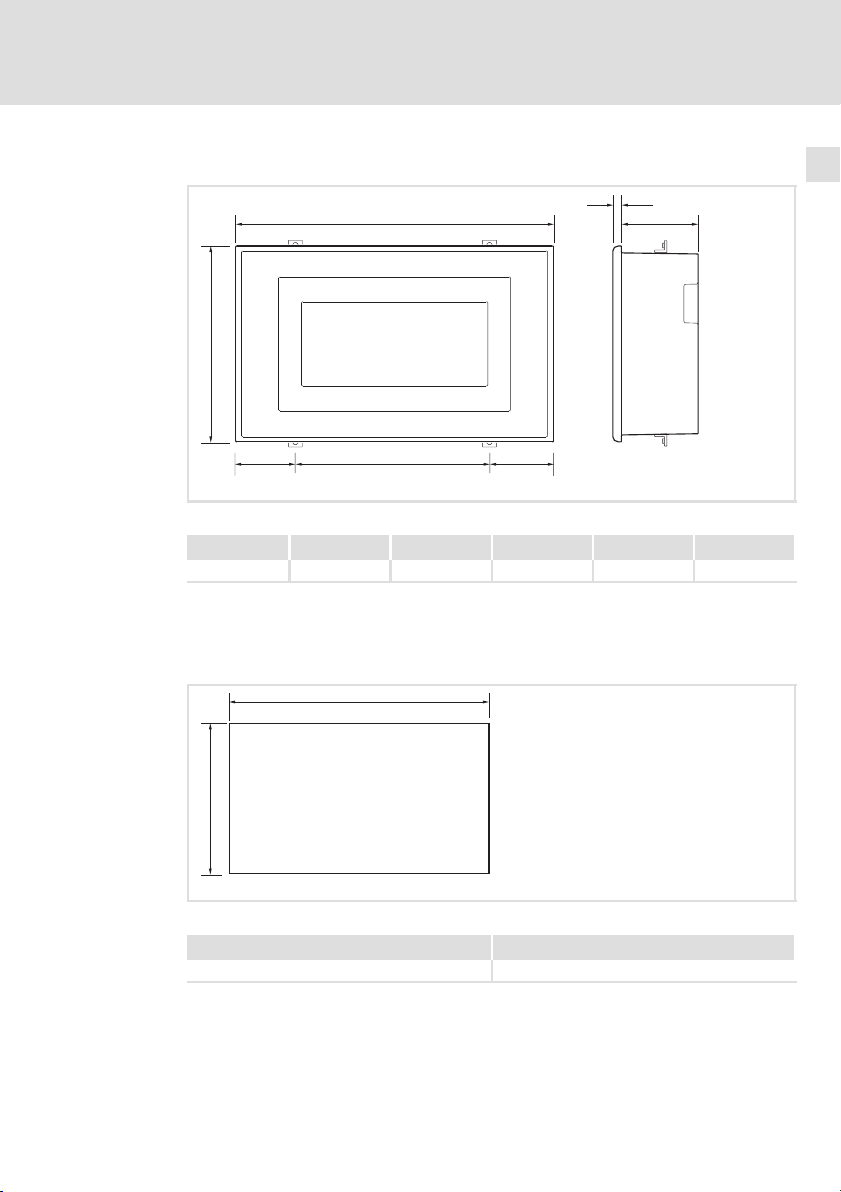
2.3 Abmessungen
b
c
Abb. 2−2 Abmessungen
a [mm] b [mm] c [mm] d [mm] e [mm] f [mm]
166.0 100.0 32.0 4.0 39.6 102.0
2.4 Einbauausschnitt
a
f
a
c
d
e
h502_001
b
Abb. 2−3 Einbauausschnitt
EDBPM−H502 DE/EN/FR 5.1
a [mm] b [mm]
157.0 91.0
h502_02
19
Page 20
3
Mechanische Installation
Bedieneinheit einbauen
3 Mechanische Installation
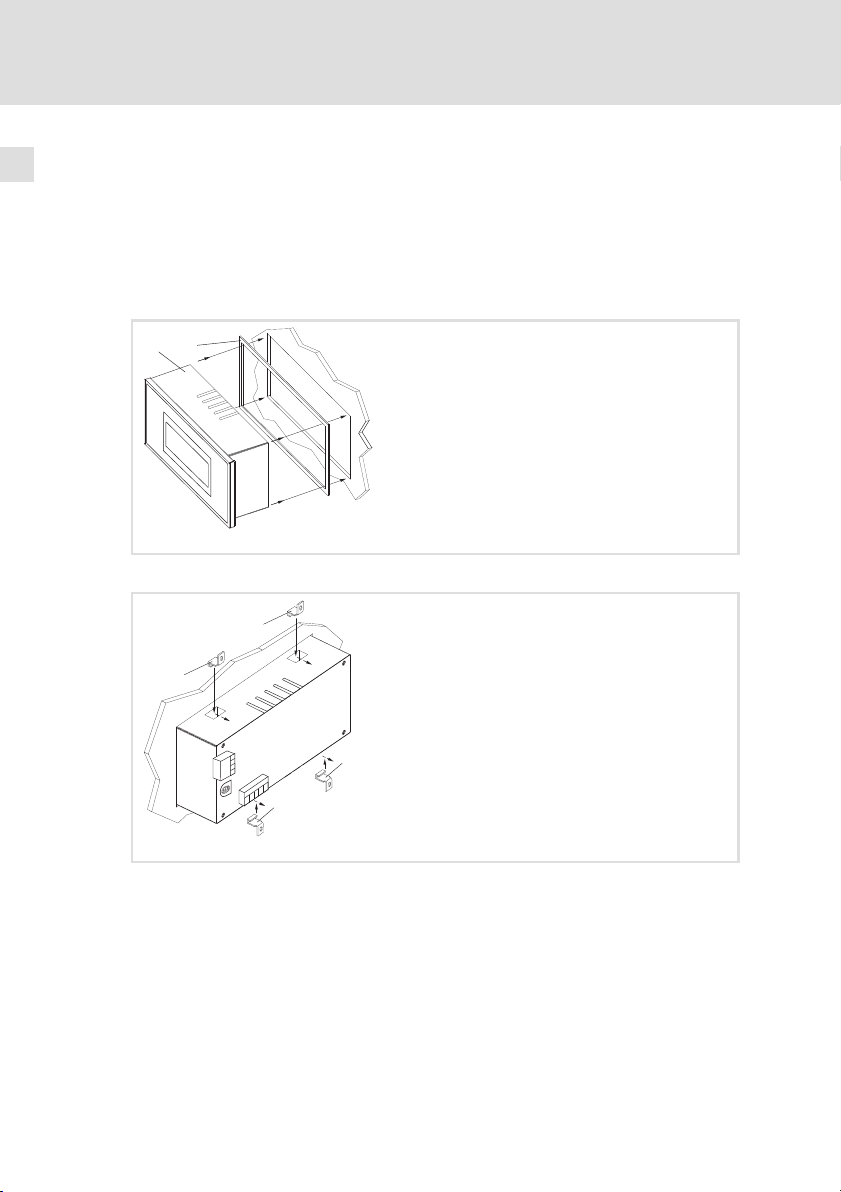
3.1 Bedieneinheit einbauen
Die Maße für den Einbauausschnitt entnehmen Sie den technischen Daten.
( 19)
So befestigen Sie die Bedieneinheit:
0
1
1. Bedieneinheit mit Dichtung in den Einbauausschnitt schieben.
2
h502_003
20
2
800mA
FUSE
10W
+(18-32)VDC
1
0VDC
2
N.C.
3
N.C.
4
CAN+
Shield
5
CAN-
ASP8
4
V-
3
2
1
2
2
2. Befestigungsschellen in die Öffnungsschlitze der Bedieneinheit
schieben.
EDBPM−H502 DE/EN/FR 5.1
h502_004
Page 21
Mechanische Installation
Bedieneinheit einbauen
2
3
2
3
A
m
0
0
8
E
S
U
F
+(18-32)VDC 10W
1
0VDC
2
N.C.
3
4
N.C.
CAN+
Shield
5
8
CAN-
P
S
A
4
V-
3
2
1
3
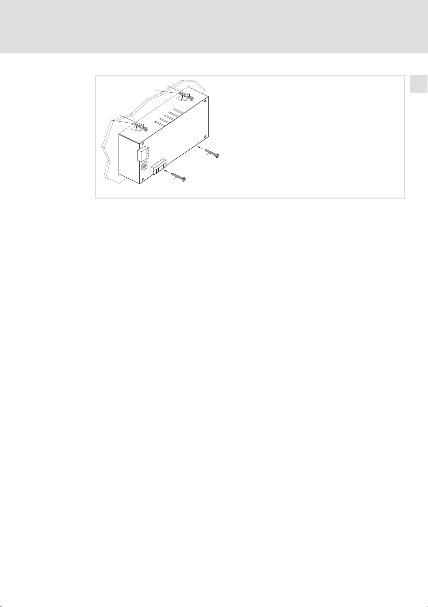
3. Schrauben gegen die Einbautafel drehen und festziehen.
3
3
h502_005
EDBPM−H502 DE/EN/FR 5.1
21
Page 22
4
Elektrische Installation
Versorgungsspannung anschließen
4 Elektrische Installation
Stop!
ƒ Beschädigung angeschlossener Geräte. Verbinden Sie den
PE−Leiter so wie es in der Abbildung dargestellt ist!
ƒ Bedieneinheit nur im spannungslosen Zustand verdrahten!
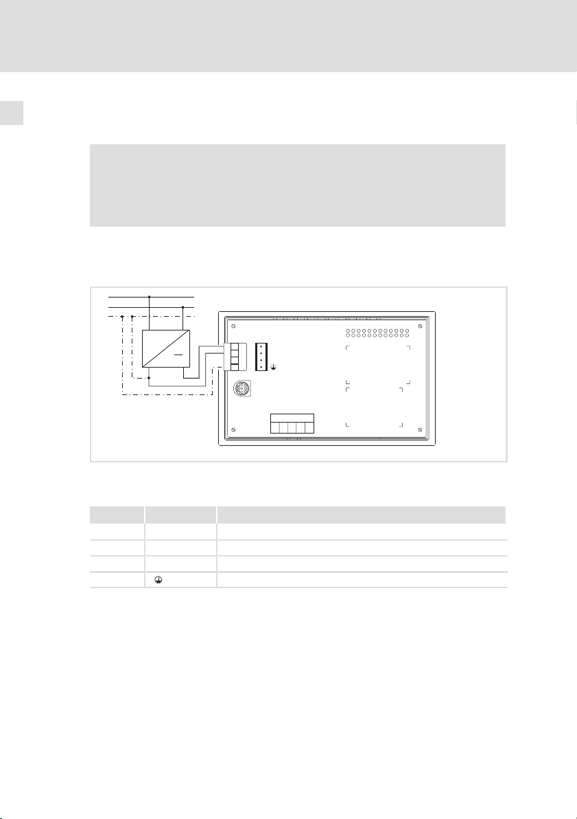
4.1 Versorgungsspannung anschließen
L1
N
PE
~
+18…32VDC
1234
FUSE 800 mA
1
2
3
4
ASP8
+(18-32) VDC 10W
0 VDC
N. C.
Shield
N.C.
CAN+
V-
CAN-
1234 5
22
Abb. 4−1 Anschluss der Versorgungsspannung
Klemmenbelegung
Klemme Bezeichnung Erläuterung
1 DC +24 V Versorgungsspannung (DC +18 V ... 32 V)
2 DC 0 V GND Versorgungsspannung, Bezugspotential
3 n. c. Nicht angeschlossen
4 PE−Potential
h502_006
EDBPM−H502 DE/EN/FR 5.1
Page 23
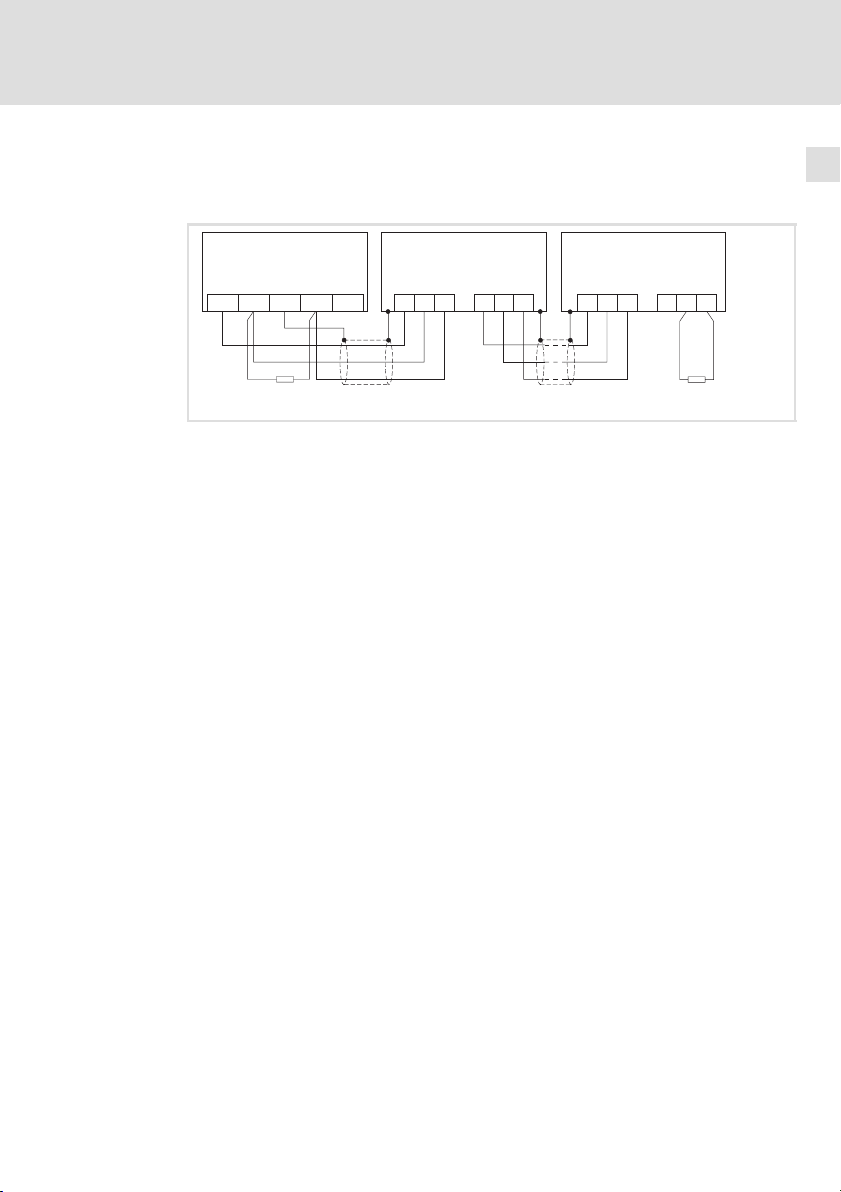
4.2 Systembus (CAN) verdrahten
Prinzipieller Aufbau
Elektrische Installation
Systembus (CAN) verdrahten
4
A
(H315)
1
ShieldCAN--V CAN+ N.C.
120
Abb. 4−2 Verdrahtung des Systembus (CAN)
Busteilnehmer 1
A
1
A
Busteilnehmer 2
2
A
Busteilnehmer n
n
CG LO HI
A
2
CG LO HI
A
n
CG LO HI CG LO
HI
120
h315_004
EDBPM−H502 DE/EN/FR 5.1
23
Page 24
4
Elektrische Installation
Systembus (CAN) verdrahten
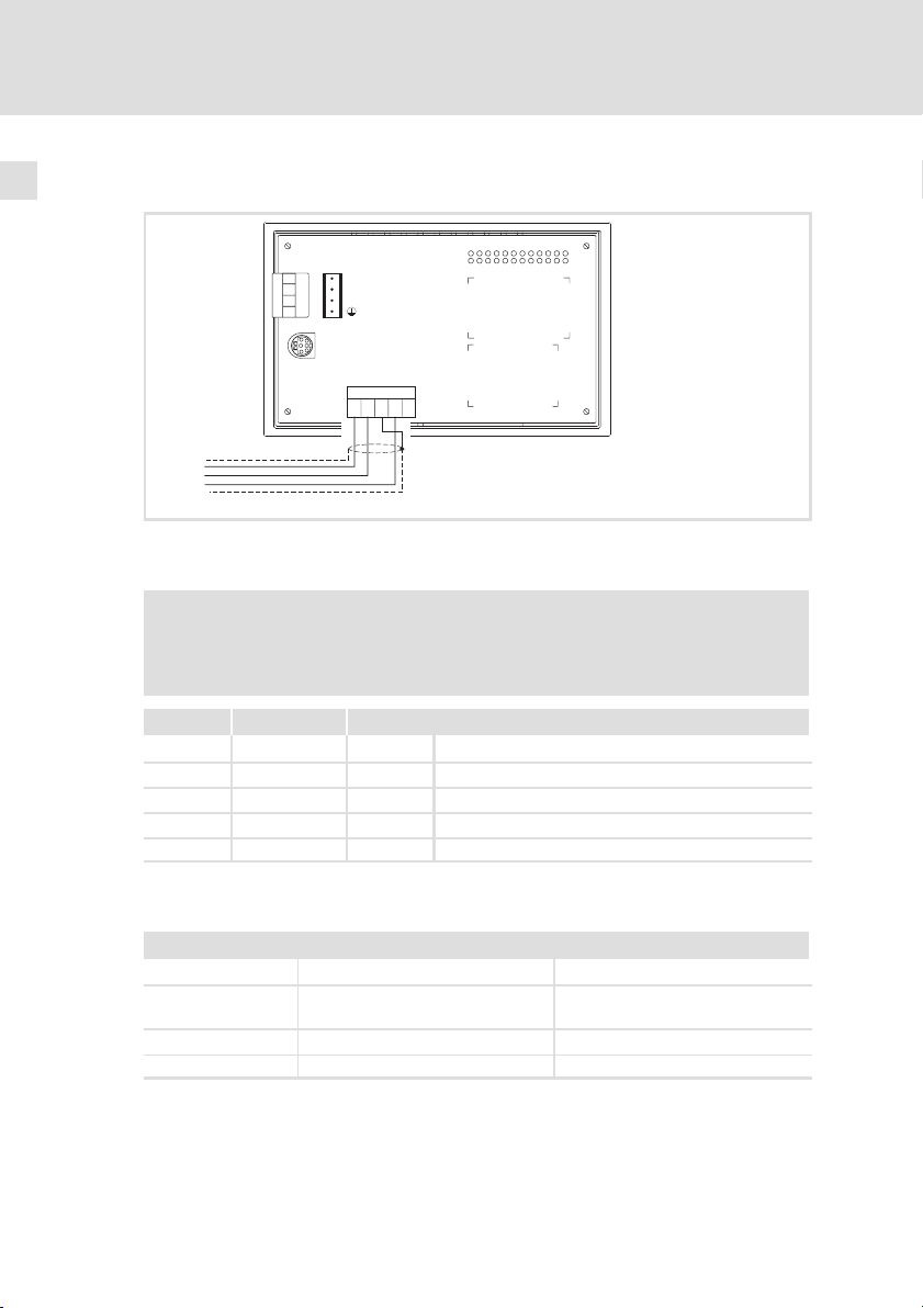
Anschluss
FUSE 800 mA
1234
1
+(18-32) VDC 10W
2
0 VDC
3
N. C.
4
ASP8
Shield
N.C.
CAN+
V-
CAN-
1234 5
CAN-GND
CAN-LO
CAN-HI
h502_012
Abb. 4−3 Anschluss Systembus (CAN)
Klemmenbelegung
Stop!
Schließen Sie einen 120 W Abschlusswiderstand am ersten und
letzten Bus−Teilnehmer an.
24
Klemme Bezeichnung Erläuterung
1V− GND Bezugspotential
2 CAN− LO Systembus LOW (Datenleitung)
3 Shield Schirm des Systembus−Kabels auflegen
4 CAN+ HI Systembus HIGH (Datenleitung)
5 n. c. Nicht angeschlossen
Folgen Sie bei der Verwendung des Übertragungskabels unseren Empfehlungen:
Spezifikation des Übertragungskabels
Gesamtlänge £ 300 m £ 1000 m
Kabeltyp LIYCY 2 x 2 x 0,5 mm
(paarverseilt mit Abschirmung)
Leitungswiderstand £ 80 W/km £ 80 W/km
Kapazitätsbelag £ 130 nF/km £ 60 nF/km
2
CYPIMF 2 x 2 x 0,5 mm
2
(paarverseilt mit Abschirmung)
EDBPM−H502 DE/EN/FR 5.1
Page 25

5 Inbetriebnahme
5.1 Erstes Einschalten
Für die Inbetriebnahme ist eine vollständige Verdrahtung des Systembus notwendig.
Überprüfen Sie vor dem Einschalten der Versorgungsspannung ...
ƒ die gesamte Verdrahtung auf Vollständigkeit und Kurzschluss,
ƒ ob das Bussystem beim physikalisch ersten und letzten Busteilnehmer
abgeschlossen ist.
Inbetriebnahme
Erstes Einschalten
5
EDBPM−H502 DE/EN/FR 5.1
25
Page 26
5
Inbetriebnahme
Projekt in die Bedieneinheit übertragen
Bedieneinheit und PC verbinden
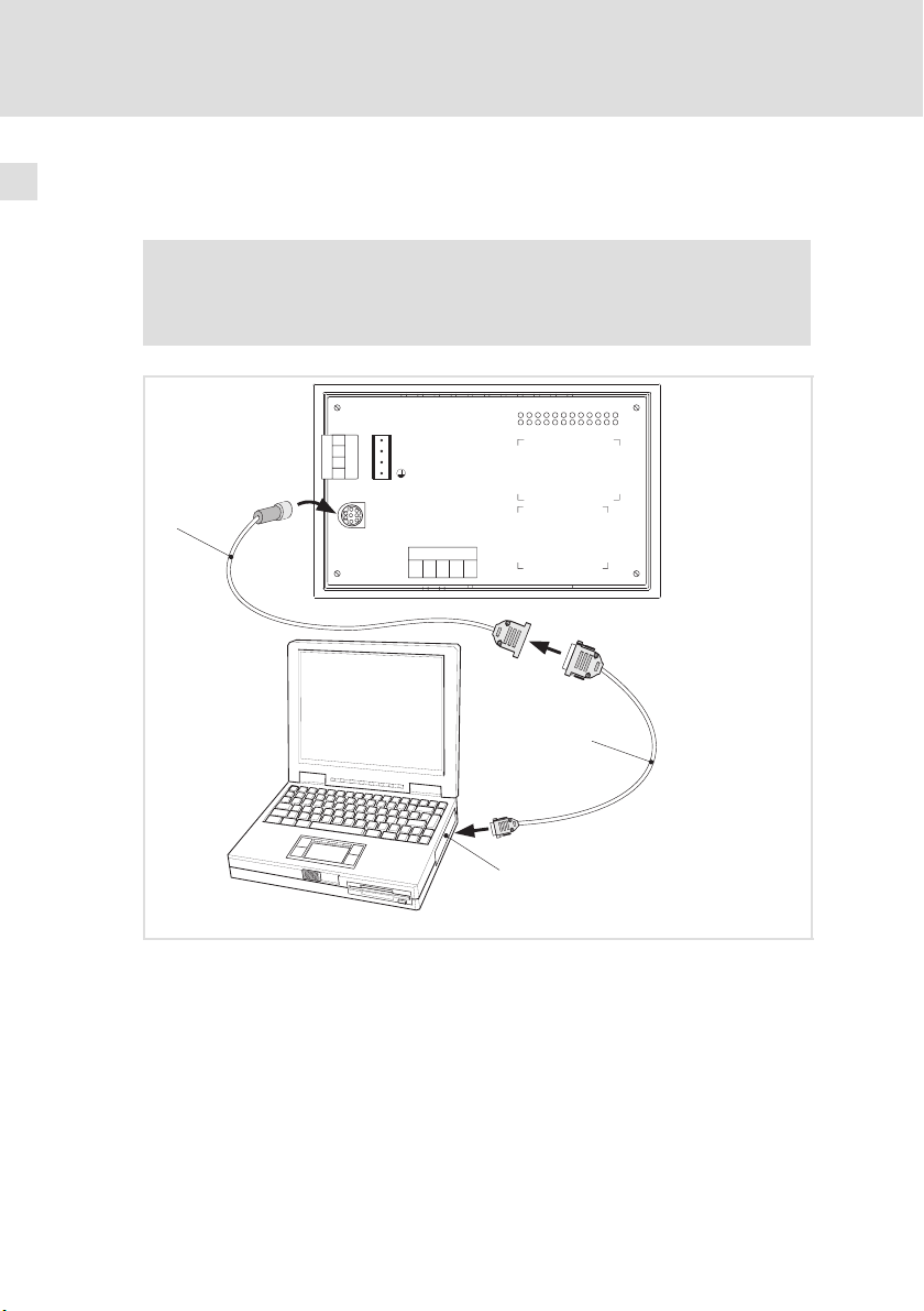
5.2 Projekt in die Bedieneinheit übertragen
5.2.1 Bedieneinheit und PC verbinden
Stop!
Die Verbindung zwischen PC und Bedieneinheit nur bei
ausgeschalteten Geräten herstellen!
FUSE 800 mA
1234
1
+(18-32) VDC 10W
2
0 VDC
3
N. C.
4
0
ASP8
l
HMI Designer
Shield
V-
CAN-
1234 5
CAN+
N.C.
1
26
2
Abb. 5−1 Bedieneinheit und PC verbinden
1. Programmieradapter EPZ−H111 auf die ASP8−Schnittstelle stecken.
2. Downloadkabel EPZ−H110 mit Programmieradapter EPZ−H111
verbinden.
3. Downloadkabel EPZ−H110 auf COM1 oder COMx am PC stecken.
EDBPM−H502 DE/EN/FR 5.1
h502_007
Page 27

Inbetriebnahme
Projekt in die Bedieneinheit übertragen
Projekt−Download
5
5.2.2 Projekt−Download
Hinweis!
Im »HMI Designer« können Sie auswählen, ob mit dem Laden des
Projekts gleichzeitig die Firmware aktualisiert werden soll.
Die Firmware muss immer beim ersten Download eines Projekts in
die Bedieneinheit bzw. nach einem Update des Projektierungstool
»HMI Designer« aktualisiert werden.
Tipp!
Beispiel−Projekte für die Bedieneinheit finden Sie im
Projektierungstool »HMI Designer« unter Datei Öffnen...
Samples.
EDBPM−H502 DE/EN/FR 5.1
27
Page 28
5
Inbetriebnahme
Projekt in die Bedieneinheit übertragen
Projekt−Download
0
3
1
Port : NET
Driver : CAN Lenze M
Ver : X.XX
Addr : NO ADDRESS
Error : RESET
2
PROG
TRANS
PAGE
ESC
H502 TRANSFER PAGE
BOOT and RAM check: OK
FIRMWARE check : OK
WAITING FOR DOWNLOAD FROM ASP
*** ***
h502_013
So übertragen Sie ein Projekt in die Bedieneinheit:
1. PC einschalten und Projektierungstool »HMI Designer« starten.
2. Versorgungsspannung für Bedieneinheit einschalten.
– Das Gerät wird initialisiert.
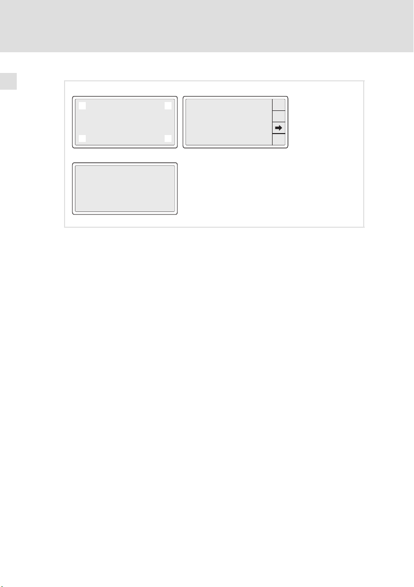
3. Nach der Initialisierung die Systemseite anwählen :
Erst das Display in einer beliebigen Ecke , , oder kurz berühren.
– Hinweis: Diese Ecke darf kein anwählbares Feld enthalten.
Anschließend sofort die diagonal gegenüberliegende Ecke kurz berühren.
– Die Systemseite erscheint .
4. Das Feld TRANS PAGE" berühren .
– Die Transfer Page erscheint .
– Wenn WAITING FOR DOWNLOAD FROM ASP angezeigt wird, ist die
Bedieneinheit bereit für den Datenempfang vom PC.
5. Gewünschtes Projekt vom HMI Designer in die Bedieneinheit übertragen.
– Siehe Handbuch "HMI Designer − Erste Schritte".
– Während des Download wird PROGRAMMING MODE" angezeigt.
Nach dem Download ist die Bedieneinheit betriebsbereit und kann über den
Systembus (CAN) mit den angeschlossenen Teilnehmern Daten austauschen.
28
EDBPM−H502 DE/EN/FR 5.1
Page 29

5.2.3 Verbindung zum PC entfernen
So entfernen Sie die Verbindung zum PC:
1. PC ausschalten.
2. Versorgungsspannung für Bedieneinheit abschalten.
3. Programmieradapter EPZ−H111 an der Bedieneinheit und Downloadkabel
EPZ−H110 am PC abziehen.
4. Versorgungsspannung für Bedieneinheit einschalten.
Die Bedieneinheit ist betriebsbereit.
Inbetriebnahme
Projekt in die Bedieneinheit übertragen
Verbindung zum PC entfernen
5
EDBPM−H502 DE/EN/FR 5.1
29
Page 30
5
Inbetriebnahme
Statusmeldungen der Bedieneinheit
5.3 Statusmeldungen der Bedieneinheit
Sie können jederzeit den Status der Bedieneinheit abfragen. Sie erhalten Informationen über:
ƒ Die Schnittstelle (Port)
ƒ Den Namen des geladenen Treibers (Driver)
ƒ Die Version des geladenen Treibers (Ver)
ƒ Die Netzadresse der Bedieneinheit (Addr)
ƒ Die zuletzt aufgetretene Störung (Error)
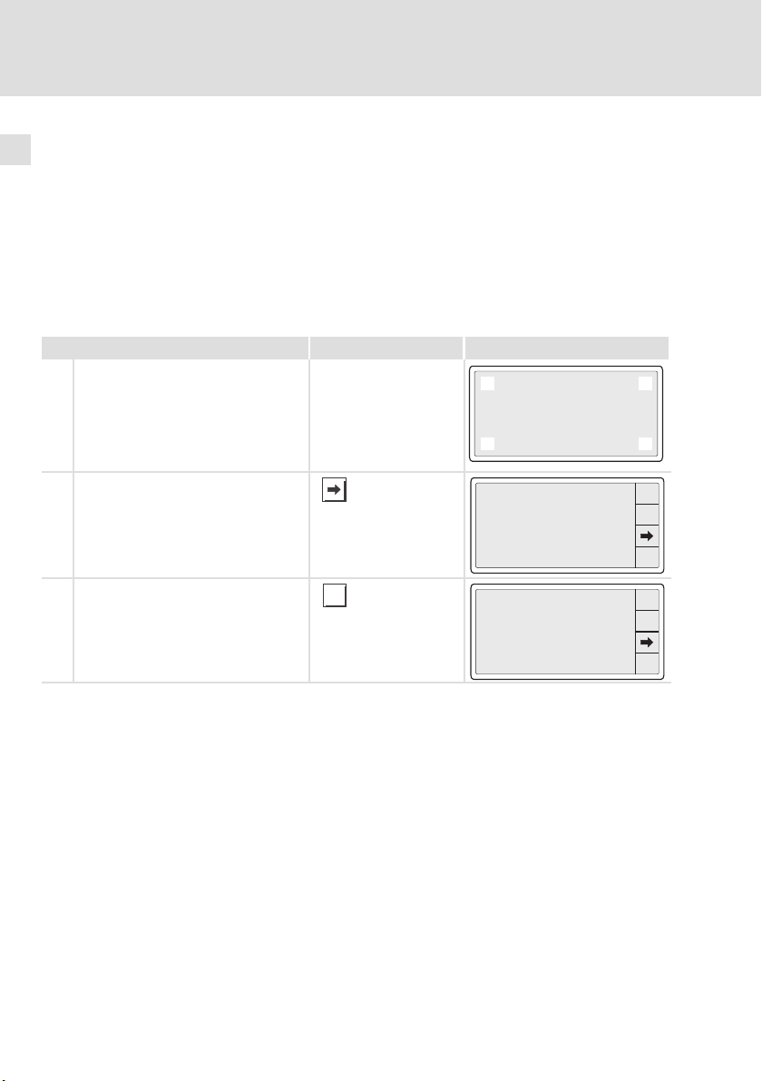
Sie möchten ... Berühren Sie die Felder ... Beispiel
A den Status der Bedieneinheit abfragen.
1. Das Display in einer beliebigen Ecke
, , oder kurz berühren.
– Hinweis: Diese Ecke darf kein
anwählbares Feld enthalten.
2. Sofort die diagonal gegenüberliegende Ecke kurz berühren.
B zwischen den Statusanzeigen mehrerer
Ports umschalten.
l Z. B. zwischen CAN−Port und ASP−Port
l Statusmeldungen werden nur bei be-
legtem / benutztem Port angezeigt
0
3
Port : NET
Driver : CAN Lenze M
Ver : X.XX
Addr : NO ADDRESS
Error : RESET
1
2
PROG
TRANS
PAGE
ESC
C die Statusanzeige schließen.
30
ESC
Port : NET
Driver : CAN Lenze M
Ver : X.XX
Addr : NO ADDRESS
Error : RESET
EDBPM−H502 DE/EN/FR 5.1
PROG
TRANS
PAGE
ESC
Page 31

Inbetriebnahme
Datum/Uhrzeit und Kontrast einstellen
5
5.4 Datum/Uhrzeit und Kontrast einstellen
Sie möchten ... Berühren Sie die Felder ... Beispiel
A
Datum/Uhrzeit und Kontrast am Display
einstellen.
1. Das Display in einer beliebigen Ecke
0
, , oder kurz berühren.
– Hinweis: Diese Ecke darf kein
anwählbares Feld enthalten.
2. Sofort die diagonal
gegenüberliegende Ecke kurz
3
berühren.
3. Menü für Uhrzeit/Datum und Kontrast anwählen.
B
Datum/Uhrzeit einstellen.
1. Feld "SET CLOCK" berühren, um das
Menü anzuwählen.
2. Gewünschtes Feld anwählen.
3. Wert ändern.
4. Ggf. Schritt 2. und 3. wiederholen,
um weitere Werte zu ändern.
PROG
oder
oder
Port : NET
Driver : CAN Lenze M
Ver : X.XX
Addr : NO ADDRESS
Error : RESET
12.50.10 13/09/00
5. Bestätigen Sie die Eingabe.
– Das Menü für Uhrzeit/Datum und
Kontrast wird angezeigt.
C
Kontrast am Display einstellen.
1. Feld "SET CONTRAST" berühren, um
das Menü anzuwählen.
SET CONTRAST : 04
SET CLOCK:
Wed,13/09/00
12:50:10
SET CONTRAST : 04
SET CLOCK:
Wed,13/09/00
12:50:10
ESC
1
2
PROG
TRANS
PAGE
ESC
ESC
ESC
2. Kontrast einstellen.
mehr Kontrast
weniger Kontrast
3. Bestätigen Sie die Eingabe.
– Das Menü für Uhrzeit/Datum und
Kontrast wird angezeigt.
D Menü Datum/Uhrzeit und Kontrast ver-
lassen und die Statusanzeige schließen.
EDBPM−H502 DE/EN/FR 5.1
ESC
CONTRAST : 04
ESC
2x
31
Page 32

6
Bedienung
Tastenfunktionen
6 Bedienung
6.1 Tastenfunktionen
Tasten Funktion Erläuterung
...
F10
F1
...
0
6/F
SHIFT
+/-
+
.
1/A
6/F
...
frei programmierbar Die Funktionen der Touch button F1 ... F10 sind
<0> ... <9> Numerische Tasten für die Dateneingabe
<1/A> ... <6/F> Alphanumerische Tasten für die hexadezimale
<+/−> Vorzeichen eingeben
<·> Gleitkomma eingeben
über die Software »HMI Designer« programmierbar. Lenze−Einstellung: Keine Funktion
Dateneingabe
ESC
<ESC> Parametereingabe abbrechen; Hilfe−, Informa-
<Pfeil auf> Parameterebene:
<Pfeil ab> Parameterebene:
<Pfeil links> Parameterebene: Cursor auf das vorherige Zei-
<Pfeil rechts> Parameterebene: Cursor auf das nächste Zeichen
<Enter> Eingegebenen Wert übernehmen
tions−, Alarm− und Statusmeldungen verlassen
l Vorherigen dynamischen Text anwählen
l Vorheriges alphanumerisches Zeichen anwäh-
len
l Nächsten dynamischen Text anwählen
l Nächstes alphanumerisches Zeichen anwäh-
len
chen stellen
stellen
32
EDBPM−H502 DE/EN/FR 5.1
Page 33

Bedienung
Daten eingeben
6
6.2 Daten eingeben
Das Eingeben oder Ändern von Daten ist Schritt für Schritt dargestellt und wird
an einem Beispiel erläutert.
Sie möchten ... Berühren Sie die Felder ... Beispiel
A ein Menü/eine Seite anwählen.
l Berühren Sie das gewünschte Feld.
B in die Parameter−Ebene wechseln.
l Berühren Sie das Parameterfeld.
– Der Cursor stellt sich auf die rechte
Ziffer.
– In einem alphanumerischen oder
dynamischen Textfeld stellt sich
der Cursor auf das linke Zeichen
(siehe J oder I).
C
einen numerischen Wert vollständig neu
eingeben.
1. Wechseln Sie in die Parameter−Ebene
(siehe B).
2. Lassen Sie den Cursor auf der rechten
Ziffer stehen.
3. Geben Sie den Wert der ersten Stelle
ein.
– Alle anderen Stellen werden auf
Null gesetzt.
4. Geben Sie den Wert der nächsten
Stelle ein.
– Die eingegebenen Ziffern werden
eine Stelle nach links geschoben.
...
0
...
0
-9876
+/-
-9876
+/-
0001
9
+/-
9
0012
+/-
ESC
0
1
.
4
7
0
1
.
4
7
0
1
.
4
7
0
1
.
4
7
3
2
5
6
8
9
ESC
3
2
5
6
8
9
ESC
3
2
5
6
8
9
ESC
3
2
5
6
8
9
5. Geben Sie ggf. ein Gleikomma ein.
Hinweis
Sie können ein Gleitkomma nur einfügen, wenn das Feld als "Floating Point" definiert ist (siehe Projektierungstool »HMI Designer«).
6. Wiederholen Sie Schritt 4. bis Sie den
Wert vollständig eingegeben haben.
7. Geben Sie ggf. ein Vorzeichen ein.
8. Bestätigen Sie die Eingabe.
– Der Cursor wechselt in die Menü−
Ebene.
EDBPM−H502 DE/EN/FR 5.1
.
+/-
012.
+/-
12.34
+/-
0
1
2
.
0
.
5
4
7
8
1
2
5
4
7
8
ESC
3
6
9
ESC
3
6
9
33
Page 34

6
Bedienung
Daten eingeben
D
eine einzelne numerische Ziffer ändern.
1. Wechseln Sie in die Parameter−Ebene
(siehe B).
2. Wählen Sie die gewünschte Ziffer.
3. Ändern Sie die Ziffer.
4. Bestätigen Sie die Eingabe.
– Der Cursor wechselt in die Menü−
Ebene.
E
einen hexadezimalen Wert vollständig
neu eingeben.
1. Wechseln Sie in die Parameter−Ebene
(siehe B).
2. Lassen Sie den Cursor auf der rechten
Ziffer stehen.
BeispielBerühren Sie die Felder ...Sie möchten ...
12. 49
3/C
6/F
ESC
3
6
9
ESC
9
0
1
1/A
4/D
2
5
4
7
8
2/B
5/E
7
8
...
0
9
.
+/-
1A3F
0
SHIFT
3. Geben Sie den Wert der ersten Stelle
ein.
– Alle anderen Stellen werden auf
Null gesetzt.
numerischer Wert
alphanumerischer Wert
4. Geben Sie den Wert der nächsten
Stelle ein.
– Die zuvor eingegebenen Ziffern
werden eine Stelle nach links geschoben.
numerischer Wert
alphanumerischer Wert
5. Wiederholen Sie Schritt 4. bis Sie den
Wert vollständig eingegeben haben.
6. Bestätigen Sie die Eingabe.
– Der Cursor wechselt in die Menü−
Ebene.
1/A
1/A
000B
0
1/A
2/B
4/D
1/A
4/D
5/E
7
8
2/B
5/E
7
8
...
0
0
9
SHIFT
...
6/F
00BD
0
6/F
SHIFT
9
...
...
3/C
6/F
3/C
6/F
ESC
9
ESC
9
34
EDBPM−H502 DE/EN/FR 5.1
Page 35

F
eine einzelne hexadezimale Ziffer ändern.
1. Wechseln Sie in die Parameter−Ebene
(siehe B).
2. Wählen Sie die gewünschte Ziffer.
3. Ändern Sie die Ziffer.
numerischer Wert
alphanumerischer Wert
4. Bestätigen Sie die Eingabe.
– Der Cursor wechselt in die Menü−
Ebene.
G einen binären Wert vollständig neu ein-
geben.
1. Wechseln Sie in die Parameter−Ebene
(siehe B).
2. Geben Sie den neuen Wert ein wie in
C beschrieben.
1/A
Bedienung
6
Daten eingeben
BeispielBerühren Sie die Felder ...Sie möchten ...
13FC
0
1/A
2/B
4/D
...
0
9
SHIFT
...
6/F
0001
0
5/E
7
8
1
3/C
6/F
ESC
9
ESC
H eine einzelne binäre Ziffer ändern.
1. Wechseln Sie in die Parameter−Ebene
(siehe B).
2. Geben Sie den neuen Wert ein wie in
D beschrieben.
I ein dynamisches Textfeld ändern.
1. Wechseln Sie in die Parameter−Ebene
(siehe B).
EDBPM−H502 DE/EN/FR 5.1
1101
0
1
ESC
35
Page 36

6
Bedienung
Daten eingeben
J
einen Rezeptnamen ändern.
1. Wechseln Sie in die Parameter−Ebene
(siehe B).
2. Wählen Sie das gewünschte Zeichen. oder
3. Ändern Sie das Zeichen über die Tastatur.
4. Wiederholen Sie Schritt 2. und 3. bis
der neue Name eingegeben ist (z. B
REZEPTUR1").
5. Bestätigen Sie die Eingabe.
– Der Cursor wechselt in die Menü−
Ebene.
6. Ändern Sie den Text.
nächster Text
vorheriger Text
7. Bestätigen Sie die Eingabe.
– Der Cursor wechselt in die Menü−
Ebene.
K
ein Symbol in einem Symbolfeld ändern.
1. Wechseln Sie in die Parameter−Ebene
(siehe B).
2. Ändern Sie das Symbol.
(z. B. , , , )
nächstes Symbol
BeispielBerühren Sie die Felder ...Sie möchten ...
REZEPT1
SP
ESC
ON
5
6
0
1
2
3
Q
W
E
R
S
D
A
F
V
Z
X
C
~
‘
<
>
[
ESC
7
4
T
G
B
[
:
8
9
U
V
I
P
O
_
J
H
K
L
-
=
N
]
“
+
M
{
}
;
/
?
ESC
vorheriges Symbol
3. Bestätigen Sie die Eingabe.
– Der Cursor wechselt in die Menü−
Ebene.
L
einen Wert über ein Balkendiagramm
eingeben.
1. Wechseln Sie in die Parameter−Ebene
(siehe B).
2. Geben Sie den Wert ein.
– VAL" zeigt den eingegebenen
Wert numerisch an.
3. Bestätigen Sie die Eingabe.
– Der Cursor wechselt in die Menü−
Ebene.
36
oder
VAL:36
MAX:100Min:0
ESC
EDBPM−H502 DE/EN/FR 5.1
Page 37

Bedienung
Informationsmeldung aufrufen
6
6.3 Informationsmeldung aufrufen
ƒ Informationsmeldungen
– sind Texte, die aufgrund eines Ereignisses angezeigt werden (z. B., wenn
ein Istwert eine Grenze übersteigt),
– können Sie nur aufrufen, solange das auslösende Ereignis vorhanden
ist,
– müssen Sie im Projektierungstool »HMI Designer« programmieren,
– können max. 5 Zeilen × 30 Zeichen lang sein (einfache Zeichengröße).
ƒ Die zweitletzte Zeile enthält ein programmierbares Meldungsfeld. Dieses
Feld zeigt die numerische Größe der Variablen, die die Meldung aktiviert
hat.
ƒ Die letzte Zeile zeigt Datum und Uhrzeit, wann die Meldung ausgelöst
wurde.
ƒ signalisiert, wenn eine Informationsmeldung vorhanden ist.
Symbole und Zeichen in den Informationsmeldungen
Symbole und Zeichen in der
Zeile Datum/Uhrzeit
* Die Informationsmeldung wurde zum erstenmal aufgerufen
HELP Der Informationsmeldung ist eine Hilfe zugeordnet. ( 40)
Sie möchten ... Berühren Sie die Felder... Beispiel
A eine Informationsmeldung aufrufen.
l Eine Seite kann max. 2 Informations-
meldungen anzeigen.
Bedeutung
Druck uebersteigt
die Sicherheitsgrenze
125.5
13-09-2000 10:45a HELP
Temperatur uebersteigt
die Sicherheitsgrenze
1700
13-09-2000 10:55a HELP
ESC
B die nächsten Informationsmeldungen
anwählen.
C die Informationsmeldungen schließen.
EDBPM−H502 DE/EN/FR 5.1
ESC
oder
Wasserstand unterhalb
der Grenze
-10
13-09-2000 11:00a HELP
ESC
37
Page 38

6
Bedienung
Alarmmeldungen aufrufen
6.4 Alarmmeldungen aufrufen
ƒ Alarmmeldungen
– sind Texte, die aufgrund eines Ereignisses angezeigt werden (z. B., wenn
ein Istwert eine Grenze übersteigt),
– müssen Sie im Projektierungstool »HMI Designer« programmieren,
– können max. 5 Zeilen × 30 Zeichen lang sein (einfache Zeichengröße),
– werden in einem Alarmregister chronologisch nach Datum und Uhrzeit
gespeichert.
ƒ Die zweitletzte Zeile enthält ein programmierbares Meldungsfeld. Dieses
Feld zeigt die numerische Größe der Variablen, die die Meldung aktiviert
hat.
ƒ Die letzte Zeile zeigt Datum und Uhrzeit, wann die Meldung ausgelöst
wurde.
ƒ signalisiert, wenn eine Alarmmeldung vorhanden ist.
Symbole und Zeichen in den Alarmmeldungen
1
Symbole
1)
Zeichen in der Zeile Datum/
Uhrzeit
HELP Der Alarmmeldung ist eine Hilfe zugeordnet.
Wenn eine Alarmmeldung mehrfach eingegangen ist, signalisiert das Symbol die zuletzt
eingegangene Meldung
Bedeutung
> Nicht quittierter Alarm.
# Quittierter Alarm. jedoch Alarmursache noch
< Nicht quittierter Alarm, jedoch Alarmursache
vorhanden.
nicht mehr vorhanden.
40)
(
38
EDBPM−H502 DE/EN/FR 5.1
Page 39

Bedienung
Alarmmeldungen aufrufen
Sie möchten ... Berühren Sie die Felder ... Beispiel
A eine Alarmmeldung aufrufen.
0001
0032
B weitere Alarmmeldungen anwählen.
0006
oder
C
das Alarmregister zu einer Alarmmeldung anwählen.
l Im Alarmregister ist das Auftreten
des Alarms chronologisch nach Datum und Uhrzeit gespeichert.
l Ein "H" in der linken Spalte signali-
siert, dass ein Alarmregister angewählt ist.
l Alarmregister schließen und zur
Alarmmeldung zurückkehren.
D die Alarmmeldungen schließen.
HIST
ESC
ESC
H
0001
H
0032
Druck im Tank uebersteigt
die max. Grenze
150.0
>13-09-2000 10:45a HELP
Wasserstand unterhalb der
Schwelle des Prozesses
10
>13-09-2000 10:45a
<13-09-2000 10:55a HELP
Temperatur uebersteigt
die Sicherheitsgrenze
1600
>13-09-2000 12:25p
#13-09-2000 12:30p HELP
Druck im Tank uebersteigt
die max. Grenze
150.0
>13-09-2000 10:45a
<13-09-2000 10:48a
#13-09-2000 10:55a
Wasserstand unterhalb der
Schwelle des Prozesses
10
>13-09-2000 10:45a
<13-09-2000 10:50a
#13-09-2000 10:53a
6
ESC
HIST
ESC
HIST
ESC
Hinweis!
EDBPM−H502 DE/EN/FR 5.1
ƒ Wenn der Puffer des Alarmregisters voll ist, werden keine
weiteren Alarme gespeichert.
ƒ In »HMI Designer« können Sie Befehlsbereiche definieren, um
alle Alarme zu quittieren oder den Puffer des Alarmregisters zu
leeren.
39
Page 40

6
Bedienung
Hilfemeldung aufrufen
6.5 Hilfemeldung aufrufen
ƒ Hilfemeldungen
– können Seiten− oder Informationsmeldungen zugeordnet sein,
– enthalten nützliche Hinweise, die die Bedienung erleichtern,
– müssen Sie im Projektierungstool »HMI Designer« programmieren,
– für Informationsmeldungen können max. 16 Zeilen × 34 Zeichen lang
sein (einfache Zeichengröße),
– für Projektseiten können max. 16 Zeilen × 40 Zeichen lang sein
(einfache Zeichengröße).
Sie möchten ... Berühren Sie die Felder... Beispiel
A
die Hilfe zu einer Informationsmeldung
aufrufen.
1. Berühren Sie das programmierte Feld
"HELP".
2. Hilfe schließen.
B
die Hilfe zu einer Seite aufrufen.
1. Berühren Sie das programmierte Feld,
welches mit der Funktion Hilfeseite
öffnen" belegt ist.
2. Hilfe schließen.
ESC
ESC
Druck uebersteigt
die Sicherheitsgrenze
125.5
13-09-2000 10:45a HELP
Temperatur uebersteigt
die Sicherheitsgrenze
1700
13-09-2000 10:55a HELP
ESC
40
EDBPM−H502 DE/EN/FR 5.1
Page 41

Fehlersuche und Störungsbeseitigung
Störungsmeldungen
7 Fehlersuche und Störungsbeseitigung
7.1 Störungsmeldungen
Rufen Sie die Statusmeldungen der Bedieneinheit auf, um die zuletzt aufgetretene Störungsmeldung anzuzeigen. ( 30)
Display Störung Ursache Abhilfe
NO ERROR Keine Störung − −
PR ERROR Fehlerhafter
COM BROK Kommunika-
ASIC ko1 Kommunika-
ASIC ko2
ASIC ko3
ASIC ko4
RESET
SDOERR 6
SDOERR 5
SDOERR 3
Datenaustausch
tion unterbrochen
tion mit Systembus (CAN)
unterbrochen
Verbindung zwischen Bedieneinheit und PC ist fehlerhaft
Serielles Datenkabel zwischen
Bedieneinheit und PC ist defekt
oder nicht richtig angeschlossen
l Fehlerhafte Verdrahtung
(z. B. Verpolung) des Systembus
l Fehlerhafte Parametrierung
der Schnittstelle (Baudrate,
Adresse, Identifier)
l Anschlüsse auf festen Sitz prüfen
l Leitung auf Beschädigung kontrollie-
l Sub−D−Stecker auf richtigen An-
l Serielles Datenkabel austauschen
l Verdrahtung Systembus (CAN) prü-
l Parametrierung prüfen ( HMI Desi-
ren
schluss und festen Sitz prüfen
23)
fen (
gner − Erste Schritte).
7
EDBPM−H502 DE/EN/FR 5.1
41
Page 42

Wartung8
8 Wartung
Die Bedieneinheit ist wartungsfrei, wenn die vorgeschriebenen Einsatzbedingungen eingehalten werden. ( 12)
ƒ Reinigen Sie die Bedieneinheit mit denaturiertem Äthylalkohol.
ƒ Wenn Sie ein anderes Reinigungsmittel verwenden müssen, um
Verunreinigungen zu beseitigen, beachten Sie die Angaben in der Tabelle
im Kap. 9.1. ( 43)
42
EDBPM−H502 DE/EN/FR 5.1
Page 43

9 Anhang
9.1 Chemikalienbeständigkeit
Stop!
Die Bedien−Oberfläche ist wenig beständig gegen saure
Nahrungsmittel (z. B. Tomatensaft, Zitronensaft). Verschmutzungen
deshalb gleich entfernen, sonst kann die Oberfläche beschädigt
werden.
Die folgende Tabelle zeigt die Beständigkeit der Bedien−Oberfläche (Tastatur,
Display, Touch Screen) gegen die genannten Chemikalien.
Für die Bedieneinheiten EPM−H5xx und EPM−H6xx bietet Lenze Schutzfolien an,
mit einer verbesserten Beständigkeit gegen die genannten Chemikalien.
Substanz
Aceton L L J
Ameisensäure ³ 50 % L L
Ammoniak ³ 2 % L L
Äthylenglykol L L L
Ätznatron ³ 2 % L L
Beizlösung konzentriert L
Benzin J L L J
Benzol J J L J
Benzylalkohol L L
Chlorwasserstoffsäure ³ 10 % L L
Dieselöl J J J J
Eisessig L L
Essigsäure ³ 5 % < 50 % L L L J
Ethanol L L L J
Hochdruck und Tempera-
tur > 100 °C
Isopropanol J J L J
Methanol J J L
Methylenchlorid L L
Mineralsäuren konzentriert L L
Natriumhydroxid ³ 50 % L L L
Perchlorethylen L J
Phosphorsäure ³ 30 % L L L L
Anhang
Chemikalienbeständigkeit
Bedieneinheit
EPM−H3xx EPM−H4xx EPM−H5xx
EPM−H6xx
L L
mit Schutz-
folie
9
EDBPM−H502 DE/EN/FR 5.1
43
Page 44

9
Anhang
Chemikalienbeständigkeit
Bedieneinheit
Substanz
Substanz
Salpetersäure ³ 5 % < 10 % L L L J
Schwefelsäure ³ 50 % L L L L
Toluol J J L J
Trichlorethylen L J
Unterchlorigsaures Na-
tron
Wasserstoffsuperoxyd ³ 25 % L L
EPM−H3xx EPM−H310, EPM−H312, EPM−H315
EPM−H4xx EPM−H410
EPM−H5xx EPM−H502, EPM−H505, EPM−H507, EPM−H510, EPM−H515, EPM−H520,
EPM−H6xx EPM−H605, EPM−H606
J Oberfläche ist beständig, keine sichtbare Beschädigung
L Oberfläche ist nicht beständig, wird beschädigt
nicht getestet
³ 20 % L L
EPM−H521, EPM−H525
EPM−H4xxEPM−H3xx
EPM−H5xx
EPM−H6xx
mit Schutz-
folie
44
EDBPM−H502 DE/EN/FR 5.1
Page 45

9.2 Stichwortverzeichnis
Anhang
Stichwortverzeichnis
9
A
Alarmmeldungen, 38
Allgemeine Daten, 12
Anschluss, elektischer, 13
Antriebsregler, 9
B
Baudrate, Systembus (CAN). Siehe Baudrate
Bedieneinheit
− Alarmmeldung aufrufen, 38
− Daten eingeben, 33
− Eigenschaften, 14
− Funktion der Tasten, 32
− Hilfemeldung aufrufen, 40
− Informationsmeldung aufrufen, 37
− Projekt in die übertragen, 26
− Schnittstellenbeschreibung, 18
− Statusmeldungen, 30
− Verbindung zum PC entfernen, 29
− Verbindung zum PC herstellen, 26
Bedienung, 32
Begriffsdefinitionen, 9
E
Eigenschaften, 14
Einbauausschnitt, 19
Einsatzbedingungen, 12
− Feuchtebeanspruchung, 12
− Montagebedingungen, Gewicht, 12
− Umgebungsbedingungen, klimatisch, 12
Einschalten, erstes, 25
Elektrische Daten, 13
Elektrische Installation, 22
− Versorgungsspannung anschließen, 22
Erstes Einschalten, 25
F
Fehlersuche, 41
− Störungsmeldungen, 41
Feuchtebeanspruchung, 12
H
Hilfemeldung, 40
Human Machine Interface, 9
C
Chemikalienbeständigkeit, 43
D
Daten, eingeben, 33
Datum, einstellen, 31
DC−Spannungsversorgung, 13
Display, 13
− Kontrast einstellen, 31
EDBPM−H502 DE/EN/FR 5.1
I
Inbetriebnahme, 25
− Erstes Einschalten, 25
Informationsmeldungen, 37
Installation, Systembus (CAN), 23
Installation, elektrische, 22
Installation, elektrische , Versorgungsspannung
anschließen, 22
Installation, mechanische, 20
45
Page 46

9
Anhang
Stichwortverzeichnis
K
Kabeltyp, 10 , 24
Kapazitätsbelag, 10 , 24
Kontrast, einstellen, 31
L
Leistungsaufnahme, 13
Leitungswiderstand, 10 , 24
M
Mechanische Installation, 20
Montagebedingungen, Gewicht, 12
P
PC
− Verbindung zur Bedieneinheit entfernen, 29
− Verbindung zur Bedieneinheit herstellen, 26
Projekt, in die Bedieneinheit übertragen, 26
Projekt−Download, 27
S
Speicher, 13
Statusmeldungen, 30
Störungsbeseitigung, 41
Störungsmeldungen, 41
Systembus (CAN)
− Baudrate, 13
− Verdrahtung, 23
T
Tastenfunktionen, 32
Technische Daten, 12
− DC−Spannungsversorgung, 13
− Display, 13
− Einbauausschnitt, 19
− Elektrische Daten, 13
− elektrischer Anschluss, 13
− Leistungsaufnahme, 13
− Schnittstellenbeschreibung, 18
− Speicher, 13
− Systembus (CAN), 13
U
Uhrzeit, einstellen, 31
Umgebungsbedingungen, klimatisch, 12
V
Versorgungsspannung anschließen, 22
W
Wartung, 42
46
EDBPM−H502 DE/EN/FR 5.1
Page 47

Anhang
Stichwortverzeichnis
9
EDBPM−H502 DE/EN/FR 5.1
47
Page 48

Key for the overview
Pos. Description Function
Terminal block, 4−pin 24V DC voltage supply
Minidin socket, 8−pin Serial port (ASP) for PC or PLC
Terminal block, 5−pin System bus (CAN)
48
EDBPM−H502 DE/EN/FR 5.1
Page 49

This documentation applies to ...
... the operating unit EPM−H502 with the following nameplate data or higher:
Type EPM−H502 1A 10
Product series
EPM Operating unit
Hardware version
Software version
EDBPM−H502 DE/EN/FR 5.1
49
Page 50

Document history
What is new / what has changed?
Material number Version Description
.?$O 5.1 03/2010 TD23 Change of company name
13300346 5.0 06/2009 TD23 Error correction
13294669 4.0 04/2009 TD23 New edition due to reorganisation of the company
13251833 3.0 05/2008 TD23 Change of company name to Lenze Digitec Controls
00470641 2.0 07/2003 TD23 Complete revision for series production
00466870 1.0 03/2003 TD23 First edition for field test
0Fig. 0Tab. 0
GmbH
Tip!
Documentation and software updates for further Lenze products can be found
on the Internet in the "Services & Downloads" area under
http://www.Lenze.com
50
EDBPM−H502 DE/EN/FR 5.1
Page 51

Contents i
1 Preface and general information 53 . . . . . . . . . . . . . . . . . . . . . . . . . . . . . . . . . . . .
1.1 About these Operating Instructions 53 . . . . . . . . . . . . . . . . . . . . . . . . . . . .
1.2 Terminology used 53 . . . . . . . . . . . . . . . . . . . . . . . . . . . . . . . . . . . . . . . . . .
1.3 Scope of supply 53 . . . . . . . . . . . . . . . . . . . . . . . . . . . . . . . . . . . . . . . . . . . .
2 Technical data 56 . . . . . . . . . . . . . . . . . . . . . . . . . . . . . . . . . . . . . . . . . . . . . . . . . . . .
2.1 General data and operating conditions 56 . . . . . . . . . . . . . . . . . . . . . . . .
2.2 Electrical data 57 . . . . . . . . . . . . . . . . . . . . . . . . . . . . . . . . . . . . . . . . . . . . . .
2.2.1 Features of the operating unit 58 . . . . . . . . . . . . . . . . . . . . . . .
2.2.2 Interface description 61 . . . . . . . . . . . . . . . . . . . . . . . . . . . . . .
2.3 Dimensions 62 . . . . . . . . . . . . . . . . . . . . . . . . . . . . . . . . . . . . . . . . . . . . . . . .
2.4 Mounting cutout 62 . . . . . . . . . . . . . . . . . . . . . . . . . . . . . . . . . . . . . . . . . . .
3 Mechanical installation 63 . . . . . . . . . . . . . . . . . . . . . . . . . . . . . . . . . . . . . . . . . . . .
3.1 Mounting of the operating unit 63 . . . . . . . . . . . . . . . . . . . . . . . . . . . . . . .
4 Electrical installation 65 . . . . . . . . . . . . . . . . . . . . . . . . . . . . . . . . . . . . . . . . . . . . . .
4.1 Supply voltage connection 65 . . . . . . . . . . . . . . . . . . . . . . . . . . . . . . . . . . .
4.2 Wiring of the system bus (CAN) 66 . . . . . . . . . . . . . . . . . . . . . . . . . . . . . . .
5 Commissioning 68 . . . . . . . . . . . . . . . . . . . . . . . . . . . . . . . . . . . . . . . . . . . . . . . . . .
5.1 Initial switch−on 68 . . . . . . . . . . . . . . . . . . . . . . . . . . . . . . . . . . . . . . . . . . . .
5.2 Project transfer to the operating unit 69 . . . . . . . . . . . . . . . . . . . . . . . . . . .
5.2.1 Connecting operating unit and PC 69 . . . . . . . . . . . . . . . . . . . .
5.2.2 Project download 70 . . . . . . . . . . . . . . . . . . . . . . . . . . . . . . . . . .
5.2.3 Disconnecting from the PC 72 . . . . . . . . . . . . . . . . . . . . . . . . .
5.3 Status messages of the operating unit 73 . . . . . . . . . . . . . . . . . . . . . . . . .
5.4 Date/time and contrast setting 74 . . . . . . . . . . . . . . . . . . . . . . . . . . . . . . .
6 Operation 75 . . . . . . . . . . . . . . . . . . . . . . . . . . . . . . . . . . . . . . . . . . . . . . . . . . . . . . .
6.1 Key functions 75 . . . . . . . . . . . . . . . . . . . . . . . . . . . . . . . . . . . . . . . . . . . . . .
6.2 Data input 76 . . . . . . . . . . . . . . . . . . . . . . . . . . . . . . . . . . . . . . . . . . . . . . . .
6.3 Calling up information messages 80 . . . . . . . . . . . . . . . . . . . . . . . . . . . . .
6.4 Calling up alarm messages 81 . . . . . . . . . . . . . . . . . . . . . . . . . . . . . . . . . . .
6.5 Calling up help messages 83 . . . . . . . . . . . . . . . . . . . . . . . . . . . . . . . . . . . .
7 Troubleshooting and fault elimination 84 . . . . . . . . . . . . . . . . . . . . . . . . . . . . . . .
7.1 Fault messages 84 . . . . . . . . . . . . . . . . . . . . . . . . . . . . . . . . . . . . . . . . . . . . .
EDBPM−H502 DE/EN/FR 5.1
51
Page 52

Contentsi
8 Maintenance 85 . . . . . . . . . . . . . . . . . . . . . . . . . . . . . . . . . . . . . . . . . . . . . . . . . . . . .
9 Appendix 86 . . . . . . . . . . . . . . . . . . . . . . . . . . . . . . . . . . . . . . . . . . . . . . . . . . . . . . . .
9.1 Chemical resistance 86 . . . . . . . . . . . . . . . . . . . . . . . . . . . . . . . . . . . . . . . .
9.2 Index 88 . . . . . . . . . . . . . . . . . . . . . . . . . . . . . . . . . . . . . . . . . . . . . . . . . . . . .
52
EDBPM−H502 DE/EN/FR 5.1
Page 53

Preface and general information
About these Operating Instructions
1 Preface and general information
The operating unit enables you to access codes of Lenze controllers,
9300 Servo PLCs and Drive PLCs and to control them in a comfortable way.
Communication takes place via the system bus (CAN).
The Lenze »HMI Designer« software makes programming of the operating unit
easy.
1.1 About these Operating Instructions
ƒ These Operating Instructions serve to ensure safe and trouble−free
working on and with the operating unit.
ƒ All persons working on and with the operating unit must have these
Operating Instructions available and observe the information and notes
relevant for them.
ƒ These Operating Instructions must always be complete and perfectly
readable.
1.2 Terminology used
Term Used in this text for
Controller Lenze 8200 vector and 9300 vector frequency inverter, Lenze 9300
HMI Human Machine Interface
and 9400 servo inverter
1
1.3 Scope of supply
Scope of supply Important
l 1 EPM−H502 operating unit
l 1 Operating Instructions
l 4 mounting clamps
l 4 screws
l 1 seal
l 1 terminal block, 4−pin, for connection of DC
voltage supply
l 1 terminal block, 5−pin, for system bus (CAN)
connection
EDBPM−H502 DE/EN/FR 5.1
After receipt of the delivery, immediately check
whether the items delivered match the
accompanying papers. Lenze does not accept
any liability for deficiencies claimed
subsequently.
Claim
l visible transport damage immediately to the
forwarder.
l visible deficiencies/incompleteness
immediately to your Lenze representative.
53
Page 54

1
Preface and general information
Scope of supply
For the use of the transmission cable, follow our recommendations:
Specification of the transmission cable
Total length £ 300 m
Cable type LIYCY 2 x 2 x 0.5 mm2
Cable resistance £ 80 W/km £ 80 W/km
Capacitance per unit
length
(paired with shielding)
£ 130 nF/km £ 60 nF/km
£ 1000 m
CYPIMF 2 x 2 x 0.5 mm
(paired with shielding)
2
The following pictographs and signal words are used in this documentation to
indicate dangers and important information:
Safety instructions
Structure of safety instructions:
Danger!
(characterises the type and severity of danger)
Note
(describes the danger and gives information about how to prevent
dangerous situations)
54
Pictograph and signal word Meaning
Danger of personal injury through dangerous electrical
voltage.
Danger!
Danger!
Stop!
Reference to an imminent danger that may result in
death or serious personal injury if the corresponding
measures are not taken.
Danger of personal injury through a general source of
danger.
Reference to an imminent danger that may result in
death or serious personal injury if the corresponding
measures are not taken.
Danger of property damage.
Reference to a possible danger that may result in
property damage if the corresponding measures are not
taken.
EDBPM−H502 DE/EN/FR 5.1
Page 55

Preface and general information
Application notes
Pictograph and signal word Meaning
1
Scope of supply
Note!
Tip!
Important note to ensure troublefree operation
Useful tip for simple handling
Reference to another documentation
EDBPM−H502 DE/EN/FR 5.1
55
Page 56

2
Technical data
General data and operating conditions
2 Technical data
2.1 General data and operating conditions
General data
Conformity and approval
Conformity
CE 2004/108/EC EMC Directive
Approval
UL cULus Underwriter Laboratories Inc. (File no. E189179)
Protection of persons and equipment
Enclosure
EMC
Applied standards for
limit values
Operating conditions
EN 61000−6−4
(2007)
EN 61000−6−2
(2005)
IP65 (front)
Noise emission. Restriction of use: Protection
requirements are not ensured in residential areas.
Noise immunity. Restriction of use: Protection
requirements are not ensured in residential areas.
56
Ambient conditions
Climate
Storage −20 ... +60 °C
Transport −20 ... +60 °C
Operation 0 ... +50 °C
Humidity
Mounting conditions
Weight 0.5 kg
<85 %, without condensation
EDBPM−H502 DE/EN/FR 5.1
Page 57

2.2 Electrical data
Field Values
Display
Electrical
connection
Network:
System bus (CAN)
Memory
Interfaces
Technical data
Electrical data
Type
Display format Graphical
Touchscreen Matrix 20 × 8 (12 × 16 pixels each)
Resolution 240 x 128 pixels
Visible size 94.5 × 54.5 mm
Lines × characters
Normal size
Double size
Quadruple size
Character size
Normal size
Double size
Quadruple size
Fonts Programmable
Contrast setting Software
Background illumination LED
DC voltage supply +24 VDC, (+18 ... 32 VDC)
Power consumption 10 W at 24 VDC
Fusing Miniature fuse Æ5 × 20 mm, 800 mA / F
Protocol System bus (CAN)
Network topology Line (terminated at both ends with 120 W)
System bus node Master or slave
Max. number of nodes 63
Baud rate [kbps] 20 50 125 250 500 1000
Max. bus length [m] 2500 1000 500 250 80 25
User program 640 kB
Data memory (Flash
EPROM)
Serial
ASP (8−pin Minidin socket) RS232
LCD 4 grey scale STN
16 × 40
8 × 20
4 × 10
2.3 × 5.2 mm, text: 6 × 8 pixels
4.6 × 5.8 mm, text: 12 × 16 pixels
9.1 × 11.7 mm, text: 24 × 32 pixels
16 kB
2
EDBPM−H502 DE/EN/FR 5.1
57
Page 58

2
Technical data
Electrical data
Features of the operating unit
2.2.1 Features of the operating unit
Description Values
Help for alarm messages [Number] 256
Alarms (total/active at the same time) [Number] 256/256
Alarm field [Function] Available
Alarm buffers [Number] 256
Automatic operations [Number] 32
Backup/restore [Function] Available
Bar chart [Function] Available
Print alarm register
Save alarm register on flash
Display alarm register
Operating page
Sheet feed on printer
Set general page number to
zero
Commands
Commands
Bit password [Bit] 8
Hardcopy
Help for the page
Next page
Change password
Password login
Password logout
End project
Display project information
Report
Send recipe to device
Load recipe from data
memory
Save recipe to data memory
Delete recipe
Send recipe from video
buffer to device
Display recipe index
Display page index
Change language
Save recipe received from
device to data memory
Save recipe received from
device to buffer
Preceding page
[Function] Available
[Function] Available
58
EDBPM−H502 DE/EN/FR 5.1
Page 59

Technical data
Electrical data
Features of the operating unit
ValuesDescription
Bitmap image directory [Function] Available
Arc [Function] Available
Data field [Function] Available
System variables assigned to the recipe structure [Function] Available
SUBTRACT
ENTER
Direct command
with value structure
Print [Function] Available
Printed pages (total/fields per page) [Number] 64/128
Dynamic bitmaps (with bit group structure, single
bit structure or value structure)
Dynamic texts (with bit group structure, single bit
structure or value structure)
Labels [Function] Available
Clock field with seconds [Function] Available
Clock field without seconds [Function] Available
Function
Equations [Number] 32
Information messages [Total/active at the same
Internal registers [Byte] 2048
Headers/footers [total/fields per
Circles [Function] Available
Lines [Function] Available
Macros (total/command × macro) [Number] 1024/16
OR
AND
XOR
ADD
Display page help
Display driver status page
Set bit permanently
Reset bit permanently
Reverse bit
Direct command with value
structure
Set real−time bit
Reset real−time bit
Go to page
Internal command
Macro
[Function] Available
[Number] 1024
[Number] 1024
[Function] Available
time]
header/footer]
256/256
64/128
2
1)
1)
EDBPM−H502 DE/EN/FR 5.1
59
Page 60

2
Technical data
Electrical data
Features of the operating unit
ValuesDescription
Help for messages [Number] 256
Message field [Function] Available
Multilingual texts [Number of languages] 4
Password levels [Number] 10
Programmable fonts [Function] Available
Project images [Function] Available
Rectangles [Function] Available
Reports [Number] 32
Recipes [Number/variables per
Recipe field for recipe structure [Function] Available
Buttons [Number per page] 24
Pages [Number] 64
Help for pages [Number] 64
Static bitmaps [Function] Available
System messages [Function] Available
Text lists [Function] Available
Timers [Number] 32
Touch fields [Number] 24
Limiting value and linear
correction variables
Movement variables
(movable symbolic field)
Variables
Weekday field [Function] Available
1)
Guide value limited by the project size
Threshold variables
Numerical floating−point
variables
Numerical variables (DEC,
HEX, BIN, BCD)
String variables (ASCII)
recipe]
[Number per page] 32
128/256
60
EDBPM−H502 DE/EN/FR 5.1
Page 61

Technical data
Electrical data
Interface description
2
2.2.2 Interface description
678
5
3
4
12
Fig. 2−1 ASP8 Minidin socket, 8−pin
Pin Signal
1 Rx RS232 IN
2 Tx RS232 OUT
3 n.c.
4 RTS RS232 OUT
5 CTS RS232 IN
6 n.c.
7 Signal GND
8 +5 VCC (reserved)
n.c. not connected
h310_010
EDBPM−H502 DE/EN/FR 5.1
61
Page 62

2
Technical data
Dimensions
2.3 Dimensions
b
c
Fig. 2−2 Dimensions
a [mm] b [mm] c [mm] d [mm] e [mm] f [mm]
166.0 100.0 32.0 4.0 39.6 102.0
2.4 Mounting cutout
a
f
a
c
d
e
h502_001
62
b
Fig. 2−3 Mounting cutout
a [mm] b [mm]
157.0 91.0
h502_02
EDBPM−H502 DE/EN/FR 5.1
Page 63

3 Mechanical installation
3.1 Mounting of the operating unit
The dimensions for the mounting cutout can be found in the "Technical data"
( 62)
How to mount the operating unit:
0
1
1. Push the operating unit and the seal into the mounting cutout.
2
Mechanical installation
Mounting of the operating unit
3
h502_003
2
2. Insert the mounting clamps into the slots of the operating unit.
EDBPM−H502 DE/EN/FR 5.1
800mA
FUSE
10W
+(18-32)VDC
1
0VDC
2
N.C.
3
N.C.
4
CAN+
Shield
5
CAN-
ASP8
4
V-
3
2
1
2
2
h502_004
63
Page 64

3
Mechanical installation
Mounting of the operating unit
2
3
2
3
A
m
0
80
E
S
U
F
+(18-32)VDC 10W
1
0VDC
2
N.C.
3
4
N.C.
CAN+
Shield
5
8
CAN-
P
S
A
4
V-
3
2
1
3
3
h502_005
3. Tighten the screws against the mounting board.
64
EDBPM−H502 DE/EN/FR 5.1
Page 65

4 Electrical installation
Stop!
ƒ Damage of units connected. Connect the PE conductor as shown
in the figure!
ƒ Wire the operating unit only when no voltage is applied!
4.1 Supply voltage connection
L1
N
PE
~
+18…32VDC
1234
FUSE 800 mA
1
+(18-32) VDC 10W
2
0VDC
3
N. C.
4
ASP8
V-
1234 5
Electrical installation
Supply voltage connection
Shield
N.C.
CAN+
CAN-
4
Fig. 4−1 Supply voltage connection
Terminal assignment
Terminal Identification Explanation
1 +24 VDC Supply voltage (DC +18 V ... 32 V)
2 0 VDC GND supply voltage, reference potential
3 n.c. Not connected
4 PE potential
EDBPM−H502 DE/EN/FR 5.1
h502_006
65
Page 66

4
Electrical installation
Wiring of the system bus (CAN)
4.2 Wiring of the system bus (CAN)
Principle structure
A
(H315)
1
ShieldCAN--V CAN+ N.C.
120
Fig. 4−2 Wiring of system bus (CAN)
Node 1
A
1
A
Node 2
2
A
Node n
n
CG LO HI
A
2
CG LO HI
A
n
CG LO HI CG LO
HI
120
h315_004
66
EDBPM−H502 DE/EN/FR 5.1
Page 67

Connection
FUSE 800 mA
1234
1
+(18-32) VDC 10W
2
0 VDC
3
N. C.
4
ASP8
Shield
V-
CAN-
1234 5
CAN-GND
CAN-LO
CAN-HI
Fig. 4−3 System bus (CAN) connection
Terminal assignment
Stop!
Connect a 120 W terminating resistor to the first and last bus device.
Electrical installation
Wiring of the system bus (CAN)
N.C.
CAN+
4
h502_012
Terminal Identification Explanation
1V− GND Reference potential
2 CAN− LO System bus LOW (data line)
3 Shield Connect the shield of the system bus cable
4 CAN+ HI System bus HIGH (data line)
5 n.c. Not connected
For the use of the transmission cable, follow our recommendations:
Specification of the transmission cable
Total length £ 300 m £ 1000 m
Cable type LIYCY 2 x 2 x 0.5 mm2
Cable resistance £ 80 W/km £ 80 W/km
Capacitance per unit
length
EDBPM−H502 DE/EN/FR 5.1
CYPIMF 2 x 2 x 0.5 mm
(paired with shielding)
(paired with shielding)
£ 130 nF/km £ 60 nF/km
2
67
Page 68

5
Commissioning
Initial switch−on
5 Commissioning
5.1 Initial switch−on
Commissioning requires a complete wiring of the system bus.
Before switching on the supply voltage, check ...
ƒ the complete wiring for completeness and short circuit,
ƒ whether the bus system is terminated at the first and last physical node.
68
EDBPM−H502 DE/EN/FR 5.1
Page 69

Commissioning
Project transfer to the operating unit
Connecting operating unit and PC
5
5.2 Project transfer to the operating unit
5.2.1 Connecting operating unit and PC
Stop!
Only connect PC and operating unit when the units are switched off!
FUSE 800 mA
1234
1
+(18-32) VDC 10W
2
0 VDC
3
N. C.
4
0
ASP8
l
HMI Designer
V-
CAN-
1234 5
Shield
CAN+
N.C.
1
Fig. 5−1 Connecting operating unit and PC
1. Plug the programming adapter EPZ−H111 onto the ASP8 interface.
2. Connect download cable EPZ−H110 to programming adapter EPZ−H111 .
3. Plug download cable EPZ−H110
EDBPM−H502 DE/EN/FR 5.1
2
h502_007
onto COM1 or COMx at PC.
69
Page 70

5
Commissioning
Project transfer to the operating unit
Project download
5.2.2 Project download
Note!
In the »HMI Designer« you can select whether you want to update
the firmware at the time the project is loaded.
The firmware must always be updated with the first download of a
project to the operating unit or after an update of the
»HMI Designer« planning tool.
Tip!
Sample projects for the operating unit can be found in the
»HMI Designer« planning tool under File Open... Samples.
70
EDBPM−H502 DE/EN/FR 5.1
Page 71

Commissioning
Project transfer to the operating unit
Project download
0
3
1
Port : NET
Driver : CAN Lenze M
Ver : X.XX
Addr : NO ADDRESS
Error : RESET
2
H502 TRANSFER PAGE
BOOT and RAM check: OK
FIRMWARE check : OK
WAITING FOR DOWNLOAD FROM ASP
*** ***
How to transfer a project to the operating unit:
1. Switch on the PC and start the »HMI Designer« planning tool.
2. Switch on the supply voltage for the operating unit.
– The device is being initialised.
3. When the initialisation is completed, select the system page :
Briefly touch the display in one of the corners , , or .
– Note: This corner must not contain a selectable field.
Immediately touch the diagonally opposite corner for a moment.
– The system page appears .
4. Touch the TRANS PAGE" field .
– The transfer page appears .
– When WAITING FOR DOWNLOAD FROM ASP is displayed, the
operating unit is ready to receive data from the PC.
5. Transfer the desired project from the HMI Designer into the operating unit.
– See "HMI Designer − getting started" manual.
– PROGRAMMING MODE" is displayed during the download.
When the download is completed, the operating unit is ready for operation and
can exchange data with the connected nodes via the system bus (CAN).
PROG
TRANS
PAGE
ESC
h502_013
5
EDBPM−H502 DE/EN/FR 5.1
71
Page 72

5
5.2.3 Disconnecting from the PC
Commissioning
Project transfer to the operating unit
Disconnecting from the PC
How to disconnect from the PC:
1. Switch off the PC.
2. Switch off the supply voltage for the operating unit.
3. Unplug the EPZ−H111 programming adapter from the operating unit and
the EPZ−H110 download cable from the PC.
4. Switch on the supply voltage for the operating unit.
The operating unit is now ready for operation.
72
EDBPM−H502 DE/EN/FR 5.1
Page 73

Commissioning
Status messages of the operating unit
5.3 Status messages of the operating unit
The operating unit status can be queried any time. Information can be obtained
about
ƒ the interface (Port)
ƒ the name of the loaded driver (Driver)
ƒ the version of the loaded driver (Ver)
ƒ the network address of the operating unit (Addr)
ƒ the last error (Error)
You want to ... Touch the fields ... Example
A query the status of the operating unit.
1. Briefly touch the display in one of the
corners , , or .
– Note: This corner must not contain
a selectable field.
2. Immediately touch the diagonally
opposite corner for a moment.
B switch between the status displays of
different ports.
l E.g. between CAN port and ASP port
l Status messages are only displayed
for assigned/used ports
0
3
Port : NET
Driver : CAN Lenze M
Ver : X.XX
Addr : NO ADDRESS
Error : RESET
1
2
PROG
TRANS
PAGE
ESC
5
C close the status display.
EDBPM−H502 DE/EN/FR 5.1
ESC
Port : NET
Driver : CAN Lenze M
Ver : X.XX
Addr : NO ADDRESS
Error : RESET
PROG
TRANS
PAGE
ESC
73
Page 74

5
Commissioning
Date/time and contrast setting
5.4 Date/time and contrast setting
You want to ... Touch the fields ... Example
A
set the date/time and contrast on the
display.
1. Briefly touch the display in one of the
0
corners , , or .
– Note: This corner must not contain
a selectable field.
2. Immediately touch the diagonally
opposite corner for a moment.
3. Select the menu for time/date and
contrast.
B
set date/time.
1. Touch the "SET CLOCK" field to select
the menu.
2. Select the desired field.
3. Change the value.
4. If necessary, repeat steps 2. and 3. to
change additional values.
PROG
or
or
3
Port : NET
Driver : CAN Lenze M
Ver : X.XX
Addr : NO ADDRESS
Error : RESET
12.50.10 13/09/00
5. Confirm the input.
– The menu for time/date and
contrast is displayed.
C
set the contrast of the display.
1. Touch the "SET CONTRAST" field to
select the menu.
SET CONTRAST : 04
SET CLOCK:
Wed,13/09/00
12:50:10
SET CONTRAST : 04
SET CLOCK:
Wed,13/09/00
12:50:10
ESC
1
2
PROG
TRANS
PAGE
ESC
ESC
ESC
2. Set the contrast.
More contrast
Less contrast
3. Confirm the input.
– The menu for time/date and
contrast is displayed.
D exit the date/time and contrast menu
and close the status display.
74
ESC
CONTRAST : 04
ESC
2x
EDBPM−H502 DE/EN/FR 5.1
Page 75

6 Operation
6.1 Key functions
Keys Function Explanation
...
F10
F1
...
0
6/F
SHIFT
1/A
+
+/-
.
Operation
Key functions
Freely programmable The functions of the touch buttons F1 ... F10 can
<0> ... <9> Numerical keys for entering data
<1/A> ... <6/F> Alphanumerical keys for entering hexadecimal
6/F
...
<+/−> Enter sign
<·> Enter floating point
be programmed with the »HMI Designer«
software. Lenze setting: no function
data
6
ESC
<Esc> Abort parameter entry; quit help, information,
<Up arrow> Parameter level:
<Down arrow> Parameter level:
<Left arrow> Parameter level: Place cursor on previous
<Right arrow> Parameter level: Place cursor on next character
<Enter> Accept the value entered
alarm and status messages
l Select previous dynamic text
l Select previous alphanumeric character
l Select next dynamic text
l Select next alphanumeric character
character
EDBPM−H502 DE/EN/FR 5.1
75
Page 76

6
Operation
Data input
6.2 Data input
Data input and modification are described step−by−step using examples.
You want to ... Touch the fields ... Example
A select a menu/page.
l Touch the desired field.
B change to the parameter level.
l Touch the parameter field.
– The cursor is placed on the right
digit.
– In an alphanumeric or dynamic
field, the cursor is placed on the
left character (see J or I).
C
enter a new numerical value.
1. Change to the parameter level (see B).
2. Leave the cursor on the right digit.
3. Enter the value for the first digit.
– All other digits are set to zero.
4. Enter the value for the next digit.
– The digits entered will shift one
place to the left.
...
0
...
0
-9876
0
+/-
-9876
0
+/-
0001
9
0
+/-
9
0012
0
+/-
ESC
1
.
4
7
1
.
4
7
1
.
4
7
1
.
4
7
3
2
5
6
8
9
ESC
3
2
5
6
8
9
ESC
3
2
5
6
8
9
ESC
3
2
5
6
8
9
5. If necessary, enter a floating point.
Note
Floating points can only be entered if
the field is defined as "Floating Point"
(see »HMI Designer« planning tool).
6. Repeat step 4. until the value is
complete.
7. If necessary, enter a sign.
8. Confirm the input.
– The cursor changes to the menu
level.
76
.
+/-
012.
+/-
12.34
+/-
0
1
2
.
0
.
5
4
7
8
1
2
5
4
7
8
EDBPM−H502 DE/EN/FR 5.1
ESC
3
6
9
ESC
3
6
9
Page 77

D
change a single numerical digit.
1. Change to the parameter level (see B).
2. Select the desired digit.
3. Change the digit.
4. Confirm the input.
– The cursor changes to the menu
level.
E
enter a new hexadecimal value.
1. Change to the parameter level (see B).
2. Leave the cursor on the right digit.
Operation
6
Data input
ExampleTouch the fields ...You want to ...
12. 49
ESC
2/B
5/E
3
2
5
6
8
9
ESC
3/C
6/F
8
9
0
+/-
1A3F
0
SHIFT
1
.
4
7
1/A
4/D
7
...
0
9
3. Enter the value for the first digit.
– All other digits are set to zero.
Numerical value
Alphanumerical value
4. Enter the value for the next digit.
– The digits entered before will shift
one place to the left.
Numerical value
Alphanumerical value
5. Repeat step 4. until the value is
complete.
6. Confirm the input.
– The cursor changes to the menu
level.
F
change a single hexadecimal digit.
1. Change to the parameter level (see B).
2. Select the desired digit.
3. Change the digit.
Numerical value
Alphanumerical value
4. Confirm the input.
– The cursor changes to the menu
level.
1/A
1/A
1/A
000B
...
0
0
0
9
...
6/F
...
9
...
6/F
...
9
...
6/F
0
SHIFT
00BD
0
SHIFT
13FC
0
SHIFT
1/A
4/D
1/A
4/D
1/A
4/D
2/B
5/E
7
8
2/B
5/E
7
8
2/B
5/E
7
8
3/C
6/F
3/C
6/F
3/C
6/F
ESC
9
ESC
9
ESC
9
EDBPM−H502 DE/EN/FR 5.1
77
Page 78

6
Operation
Data input
G enter a new binary value.
1. Change to the parameter level (see B).
2. Enter the new value as described
under C.
ExampleTouch the fields ...You want to ...
0001
0
1
ESC
H change a single binary digit.
1. Change to the parameter level (see B).
2. Enter the new value as described
under D.
I change a dynamic text field.
1. Change to the parameter level (see B).
J
change a recipe name.
1. Change to the parameter level (see B).
2. Select the desired character. or
3. Change the character using the
keyboard.
4. Repeat steps 2. and 3. until the new
name is entered (e.g. RECIPE1").
5. Confirm the input.
– The cursor changes to the menu
level.
6. Change the text.
Next text
Previous text
7. Confirm the input.
– The cursor changes to the menu
level.
K
change a symbol in a symbol field.
1. Change to the parameter level (see B).
2. Change the symbol.
(E.g. , , , )
Next symbol
1101
0
REZEPT1
0
Q
A
Z
SP
ESC
ON
ESC
1
1
W
S
X
5
2
3
4
V
E
R
T
D
H
F
G
N
V
B
C
[
]
~
‘
:
<
>
“
[
ESC
6
7
8
9
U
I
P
O
_
J
K
L
-
=
+
M
{
}
;
/
?
ESC
3. Confirm the input.
– The cursor changes to the menu
level.
78
Previous symbol
EDBPM−H502 DE/EN/FR 5.1
Page 79

L
enter a bar chart value.
1. Change to the parameter level (see B).
2. Enter the value.
– VAL" displays the entered value
numerically.
3. Confirm the input.
– The cursor changes to the menu
level.
Operation
6
Data input
ExampleTouch the fields ...You want to ...
or
VAL:36
MAX:100Min:0
ESC
EDBPM−H502 DE/EN/FR 5.1
79
Page 80

6
Operation
Calling up information messages
6.3 Calling up information messages
ƒ Information messages
– are texts which appear because of a certain event (e.g. if an actual value
exceeds a limit),
– can only be called up as long as the triggering event is active.
– must be programmed in the »HMI Designer« planning tool,
– can be up to 5 lines × 30 characters long (normal character size).
ƒ The second to last line contains a programmable message field. This field
indicates the numerical value of the variable that has activated the
message.
ƒ The last line shows the date and time when the message has been
triggered.
ƒ signals that an information message is present.
Symbols and characters in the information messages
Symbols and characters used in
the date/time line
* The information message has been called up for the first time
HELP Help is assigned to the information message. ( 83)
You want to ... Touch the fields ... Example
A call up an information message.
l A page can display up to
2 information messages.
Meaning
Pressure exceeds
safety limit
125.5
13-09-2000 10:45a HELP
Temperature exceeds
safety limit
1700
13-09-2000 10:55a HELP
ESC
B select the next information messages. or
C close the information messages.
80
ESC
Water level below
working threshold
-10
13-09-2000 11:00a HELP
EDBPM−H502 DE/EN/FR 5.1
ESC
Page 81

6.4 Calling up alarm messages
ƒ Alarm messages
– are texts which appear because of a certain event (e.g. if an actual value
exceeds a limit),
– must be programmed in the »HMI Designer« planning tool,
– can be up to 5 lines × 30 characters long (normal character size),
– are chronologically saved in an alarm register with time and date
stamping.
ƒ The second to last line contains a programmable message field. This field
indicates the numerical value of the variable that has activated the
message.
ƒ The last line shows the date and time when the message has been
triggered.
ƒ signals that an alarm message is present.
Symbols and characters used in alarm messages
1
Symbols
1)
Characters used in the
date/time line
HELP Help is assigned to the alarm message. ( 83)
If an alarm message has been received several times, the symbol indicates the last
incoming message
Operation
Calling up alarm messages
Meaning
> Alarm not acknowledged.
# Acknowledged alarm but alarm cause still
< Unacknowledged alarm but alarm cause no
present.
longer present.
6
EDBPM−H502 DE/EN/FR 5.1
81
Page 82

6
Operation
Calling up alarm messages
You want to ... Touch the fields ... Example
A call up an alarm message.
0001
0032
B select other alarm messages.
0006
or
C
select the alarm register for an alarm
message.
l The alarm register logs all alarms
chronologically, with time and date
stamping.
l If "H" is displayed in the left column,
an alarm register has been selected.
l Close the alarm register and go back
to the alarm message.
HIST
ESC
H
0001
H
0032
Tank pressure exceeds
safety limit
150.0
>13-09-2000 10:45a HELP
Water level below
processor limit
10
>13-09-2000 10:45a
<13-09-2000 10:55a HELP
Temperature exceeds
safety limit
1600
>13-09-2000 12:25p
#13-09-2000 12:30p HELP
Tankpressure exceeds
safety limit
150.0
>13-09-2000 10:45a
<13-09-2000 10:48a
#13-09-2000 10:55a
Water levelbelow
processor limit
10
>13-09-2000 10:45a
<13-09-2000 10:50a
#13-09-2000 10:53a
ESC
HIST
ESC
HIST
ESC
D close the alarm messages.
Note!
ƒ If the alarm register buffer is full, no more alarms are saved.
ƒ Use the »HMI Designer« to define commands for acknowledging
82
ESC
all alarms or clearing the buffer of the alarm register.
EDBPM−H502 DE/EN/FR 5.1
Page 83

Operation
Calling up help messages
6
6.5 Calling up help messages
ƒ Help messages
– can be assigned to page or information messages,
– contain useful notes to make handling easier,
– must be programmed in the »HMI Designer« planning tool,
– for information messages can be up to 16 lines × 34 characters long
(normal character size),
– for project pages can be up to 16 lines × 40 characters long (normal
character size).
You want to ... Touch the fields ... Example
A
call up the help message for an
information message.
1. Touch the programmed field "HELP".
2. Close help.
B
call up the help message for a page.
1. Touch the programmed field that is
assigned to the Open help page"
function.
2. Close help.
ESC
ESC
Pressure exceeds
safety limit
125.5
13-09-2000 10:45a HELP
Temperature exceeds
safety limit
1700
13-09-2000 10:55a HELP
ESC
EDBPM−H502 DE/EN/FR 5.1
83
Page 84

7
Troubleshooting and fault elimination
Fault messages
7 Troubleshooting and fault elimination
7.1 Fault messages
Call up the status messages of the operating unit to display the fault message
that occurred last. ( 73)
Display Fault Cause Remedy
NO ERROR No fault − −
PR ERROR Faulty data
COM BROK Communication
ASIC ko1 Communication
ASIC ko2
ASIC ko3
ASIC ko4
RESET
SDOERR 6
SDOERR 5
SDOERR 3
exchange
interrupted
with system
bus (CAN)
interrupted
Connection between operating
unit and PC is faulty
Serial data cable between
operating unit and PC is
defective or not correctly
connected
l Faulty wiring (e. g. polarity)
of the system bus
l Faulty parameterisation of
interface (baud rate,
address, identifier)
l Check that the connections are
firmly seated.
l Check cable for damages
l Check Sub−D connector for correct
connection and firm seating.
l Replace serial data cable
l Check wiring of system bus (CAN)
(
l Check parameter setting ( HMI
Designer − Getting started).
66)
84
EDBPM−H502 DE/EN/FR 5.1
Page 85

8 Maintenance
The operating unit is maintenance−free if all operating conditions described in
these Instructions are observed. ( 56)
ƒ Clean the operating unit with denatured ethyl alcohol.
ƒ If you use any other cleaning agents, please observe the information
given in the table in chapter 9.1. ( 86)
Maintenance 8
EDBPM−H502 DE/EN/FR 5.1
85
Page 86

9
Appendix
Chemical resistance
9 Appendix
9.1 Chemical resistance
Stop!
The resistance of the operating unit’s surface against acid food
(e.g. tomato juice, lemon juice) is low. For this reason remove
soilings immediately, otherwise the surface may be damaged.
The following table shows the resistance of the surfaces (keyboard, display,
touchscreen) to the listed chemicals.
For EPM−H5xx and EPM−H6xx operating units, Lenze offers protective foils with
an improved resistance against the listed chemicals.
Substance
Acetic acid ³ 5 % < 50 % L L L J
Acetone L L J
Ammonia ³ 2 % L L
Benzene J L L J
Benzole J J L J
Benzyl alcohol L L
Diesel oil J J J J
Ethanol L L L J
Ethylene glycol L L L
Formic acid ³ 50 % L L
High−pressure and
temperature > 100 °C
Hydrochloric acid ³ 10 % L L
Hydrogen peroxide ³ 25 % L L
Hypochlorous acidic
natron
Isopropanol J J L J
Methanol J J L
Methylene chloride L L
Mineral acids Concentrated L L
Nitric acid ³ 5 % < 10 % L L L J
Perchloroethylene L J
Operating unit
EPM−H3xx EPM−H4xx EPM−H5xx
EPM−H6xx
L L
³ 20 % L L
With
protective
foil
86
EDBPM−H502 DE/EN/FR 5.1
Page 87

Appendix
Chemical resistance
Operating unit
EPM−H4xxEPM−H3xx
Substance
Substance
Phosphoric acid ³ 30 % L L L L
Pickling solution Concentrated L
Pure acetic acid L L
Sodium hydroxide ³ 2 % L L
Sodium hydroxide ³ 50 % L L L
Sulphuric acid ³ 50 % L L L L
Toluol J J L J
Trichloroethylene L J
EPM−H3xx EPM−H310, EPM−H312, EPM−H315
EPM−H4xx EPM−H410
EPM−H5xx EPM−H502, EPM−H505, EPM−H507, EPM−H510, EPM−H515, EPM−H520,
EPM−H6xx EPM−H605, EPM−H606
J Surface resists, no visible damage
L Surface does not resist, visible damage
Not tested
EPM−H521, EPM−H525
EPM−H5xx
EPM−H6xx
With
protective
foil
9
EDBPM−H502 DE/EN/FR 5.1
87
Page 88

9
Appendix
Index
9.2 Index
A
Alarm messages, 81
Ambient conditions, Climatic, 56
B
Baud rate, System bus (CAN). Siehe Baud rate
C
Cable resistance, 54 , 67
Cable type, 54 , 67
Capacitance per unit length, 54 , 67
Chemical resistance, 86
Commissioning, 68
− Initial switch−on, 68
Connecting the supply voltage, 65
Connection, electrical, 57
Contrast, adjustment, 74
Controller, 53
D
Data, input, 76
Date, adjustment, 74
DC voltage supply, 57
Definitions, 53
Display, 57
− Contrast setting, 74
E
Electrical data, 57
Electrical installation, 65
− Connecting the supply voltage, 65
F
Fault messages, 84
G
General data, 56
H
Help messages, 83
Human Machine Interface, 53
Humidity, 56
I
Information messages, 80
Initial switch−on, 68
Installation, system bus (CAN), 66
Installation, electrical, 65
Installation, electrical , connecting the supply
voltage, 65
Installation, mechanical, 63
K
Key functions, 75
M
Maintenance, 85
Mechanical installation, 63
Memory, 57
Mounting conditions, Weight, 56
Mounting cutout, 62
88
EDBPM−H502 DE/EN/FR 5.1
Page 89

Appendix
Index
9
O
Operating conditions, 56
− Ambient conditions, Climatic, 56
− Humidity, 56
− Mounting conditions, Weight, 56
Operating unit
− Calling up alarm messages, 81
− Calling up help messages, 83
− Calling up information messages, 80
− Connecting with the PC, 69
− Data input, 76
− Disconnecting from the PC, 72
− Interface description, 61
− Key functions, 75
− Parameters, 58
− Project transfer, 69
− Status messages, 73
Operation, 75
P
Parameters, 58
PC
− Connecting with the operating unit, 69
− Disconnecting from the operating unit, 72
Power consumption, 57
Project
− Download, 70
− Project transfer to the operating unit, 69
S
Status messages, 73
Switch on, initial, 68
System bus (CAN)
− Baud rate, 57
− Wiring, 66
T
Technical data, 56
− DC voltage supply, 57
− Display, 57
− Electrical connection, 57
− Electrical data, 57
− Interface description, 61
− Memory, 57
− Mounting cutout, 62
− Power consumption, 57
− System bus (CAN), 57
Time, adjustment, 74
Troubleshooting, fault messages, 84
Troubleshooting and fault elimination, 84
EDBPM−H502 DE/EN/FR 5.1
89
Page 90

Légende
Pos. Description Fonction
Bornier 4 bornes Alimentation 24 V CC
Prise Minidin 8 broches Port série (ASP) pour PC ou API
Bornier 5 bornes Bus Système CAN
90
EDBPM−H502 DE/EN/FR 5.1
Page 91

Validité :
Unité de commande EPM−H502 à partir de la version ci−dessous (voir plaque signalétique) :
Type EPM−H502 1A 10
Série d’appareils
EPM Unité de commande
Version matérielle
Version logicielle
EDBPM−H502 DE/EN/FR 5.1
91
Page 92

Historique du document
Nouveautés / Modifications
Numéro de documentation
.?$O 5.1 03/2010 TD23 Changement de raison sociale
13300346 5.0 06/2009 TD23 Rectification des erreurs
13294669 4.0 04/2009 TD23 Nouvelle édition en raison de la nouvelle organisa-
13251833 3.0 05/2008 TD23 Nouvelle raison sociale : Lenze Digitec Controls
00470641 2.0 07/2003 TD23 Texte entièrement revu pour la série
00466870 1.0 03/2003 TD23 Première édition pour essais sur le terrain
Version Description
tion de l’entreprise
GmbH
0Fig. 0Tab. 0
Conseil !
Les mises à jour de logiciels et les documentations relatives aux produits Lenze
sont disponibles dans la zone "Téléchargements" du site Internet :
http://www.Lenze.com
92
EDBPM−H502 DE/EN/FR 5.1
Page 93

Sommaire i
1 Avant−propos et généralités 95 . . . . . . . . . . . . . . . . . . . . . . . . . . . . . . . . . . . . . . . .
1.1 Comment utiliser ces instructions de mise en service 95 . . . . . . . . . . . . .
1.2 Terminologie 95 . . . . . . . . . . . . . . . . . . . . . . . . . . . . . . . . . . . . . . . . . . . . . .
1.3 Equipement livré 95 . . . . . . . . . . . . . . . . . . . . . . . . . . . . . . . . . . . . . . . . . . .
2 Spécifications techniques 98 . . . . . . . . . . . . . . . . . . . . . . . . . . . . . . . . . . . . . . . . . .
2.1 Caractéristiques générales et conditions d’utilisation 98 . . . . . . . . . . . .
2.2 Caractéristiques électriques 99 . . . . . . . . . . . . . . . . . . . . . . . . . . . . . . . . . .
2.2.1 Caractéristiques de l’unité de commande 100 . . . . . . . . . . . . . .
2.2.2 Affectation de la prise 104 . . . . . . . . . . . . . . . . . . . . . . . . . . . . . .
2.3 Encombrements 105 . . . . . . . . . . . . . . . . . . . . . . . . . . . . . . . . . . . . . . . . . . . .
2.4 Encoche de montage 105 . . . . . . . . . . . . . . . . . . . . . . . . . . . . . . . . . . . . . . . .
3 Installation mécanique 106 . . . . . . . . . . . . . . . . . . . . . . . . . . . . . . . . . . . . . . . . . . . .
3.1 Montage de l’unité de commande 106 . . . . . . . . . . . . . . . . . . . . . . . . . . . . .
4 Installation électrique 108 . . . . . . . . . . . . . . . . . . . . . . . . . . . . . . . . . . . . . . . . . . . . .
4.1 Raccordement de la tension d’alimentation 108 . . . . . . . . . . . . . . . . . . . . .
4.2 Câblage du Bus Système CAN 109 . . . . . . . . . . . . . . . . . . . . . . . . . . . . . . . . .
5 Mise en service 111 . . . . . . . . . . . . . . . . . . . . . . . . . . . . . . . . . . . . . . . . . . . . . . . . . . .
5.1 Première mise en service 111 . . . . . . . . . . . . . . . . . . . . . . . . . . . . . . . . . . . . .
5.2 Téléchargement d’un projet sur l’unité de commande 112 . . . . . . . . . . . . .
5.2.1 Etablissement de la liaison entre l’unité de commande et le PC
112
5.2.2 Téléchargement du projet 113 . . . . . . . . . . . . . . . . . . . . . . . . . .
5.2.3 Déconnexion du PC 115 . . . . . . . . . . . . . . . . . . . . . . . . . . . . . . . .
5.3 Messages d’état de l’unité de commande 116 . . . . . . . . . . . . . . . . . . . . . . .
5.4 Réglages de la date/de l’heure et du contraste 117 . . . . . . . . . . . . . . . . . . .
6 Utilisation 118 . . . . . . . . . . . . . . . . . . . . . . . . . . . . . . . . . . . . . . . . . . . . . . . . . . . . . . .
6.1 Fonction des touches 118 . . . . . . . . . . . . . . . . . . . . . . . . . . . . . . . . . . . . . . . .
6.2 Saisie des données 119 . . . . . . . . . . . . . . . . . . . . . . . . . . . . . . . . . . . . . . . . . .
6.3 Affichage d’un message d’information 124 . . . . . . . . . . . . . . . . . . . . . . . . .
6.4 Afficher un message d’alarme 125 . . . . . . . . . . . . . . . . . . . . . . . . . . . . . . . .
6.5 Recherche d’une rubrique d’aide 127 . . . . . . . . . . . . . . . . . . . . . . . . . . . . . .
7 Détection des erreurs et élimination des défauts 128 . . . . . . . . . . . . . . . . . . . . . . .
7.1 Messages d’erreur 128
. . . . . . . . . . . . . . . . . . . . . . . . . . . . . . . . . . . . . . . . . .
EDBPM−H502 DE/EN/FR 5.1
93
Page 94

Sommairei
8 Maintenance 129 . . . . . . . . . . . . . . . . . . . . . . . . . . . . . . . . . . . . . . . . . . . . . . . . . . . . .
9 Annexe 130 . . . . . . . . . . . . . . . . . . . . . . . . . . . . . . . . . . . . . . . . . . . . . . . . . . . . . . . . .
9.1 Résistance aux produits chimiques 130 . . . . . . . . . . . . . . . . . . . . . . . . . . . .
9.2 Index 132 . . . . . . . . . . . . . . . . . . . . . . . . . . . . . . . . . . . . . . . . . . . . . . . . . . . . .
94
EDBPM−H502 DE/EN/FR 5.1
Page 95

Avant−propos et généralités
Comment utiliser ces instructions de mise en service
1 Avant−propos et généralités
L’unité de commande permet d’accéder aux codes des variateurs de vitesse
Lenze, du Servo PLC 9300 et du Drive PLC, ainsi que de commander ces appareils
de façon conviviale. La communication s’effectue via le Bus Système CAN.
Grâce au logiciel HMI Designer de Lenze, la programmation de l’unité de
commande est un véritable jeu d’enfant.
1.1 Comment utiliser ces instructions de mise en service
ƒ Les présentes instructions de mise en service permettent d’utiliser en
toute sécurité l’unité de commande.
ƒ Toute personne utilisant l’unité de commande doit pouvoir consulter ces
instructions à tout instant et est tenue de respecter les indications et
consignes correspondantes.
ƒ Les instructions de mise en service doivent être complètes et lisibles en
toute circonstance.
1.2 Terminologie
Terme Utilisé dans le présent document pour désigner
Variateur de vitesse les convertisseurs de fréquence 8200 vector et 9300 vector, et les
HMI une interface homme−machine (Human Machine Interface)
servovariateurs 9300 et 9400 de Lenze
1
1.3 Equipement livré
Equipement livré IMPORTANT
l 1 unité de commande EPM−H502
l 1 document "Instructions de mise en
service"
l 4 colliers de fixation
l 4 vis
l 1 joint
l 1 bornier 4 bornes pour le raccordement de
l’alimentation CC
l 1 bornier 5 bornes pour le raccordement du
Bus Système CAN
EDBPM−H502 DE/EN/FR 5.1
Vérifier à la réception que l’équipement livré est
conforme au bon de livraison. Aucune
réclamation ne pourra être formulée
ultérieurement.
En cas de
l dégâts visibles occasionnés par le transport :
réclamation immédiate auprès du
transporteur ;
l vices apparents/équipement incomplet :
réclamation immédiate auprès de l’agence
Lenze concernée.
95
Page 96

1
Avant−propos et généralités
Equipement livré
Nous vous recommandons d’utiliser les câbles suivants :
Spécifications du câble de transmission
Longueur totale £ 300 m
Type de câble LIYCY 2 x 2 x 0,5 mm2
(paire blindée)
Résistance de câble £ 80 W/km £ 80 W/km
Capacité de câble £ 130 nF/km £ 60 nF/km
£ 1000 m
CYPIMF 2 x 2 x 0,5 mm
(paire blindée)
2
Pour indiquer des risques et des informations importantes, la présente
documentation utilise les mots et symboles suivants :
Consignes de sécurité
Présentation des consignes de sécurité
Danger !
(Le pictogramme indique le type de risque.)
Explication
(L’explication décrit le risque et les moyens de l’éviter.)
Pictogramme et mot associé Explication
Situation dangereuse pour les personnes en raison
d’une tension électrique élevée
Danger !
Danger !
Stop !
Indication d’un danger imminent qui peut avoir pour
conséquences des blessures mortelles ou très graves en
cas de non−respect des consignes de sécurité
correspondantes
Situation dangereuse pour les personnes en raison d’un
danger d’ordre général
Indication d’un danger imminent qui peut avoir pour
conséquences des blessures mortelles ou très graves en
cas de non−respect des consignes de sécurité
correspondantes
Risques de dégâts matériels
Indication d’un risque potentiel qui peut avoir pour
conséquences des dégâts matériels en cas de
non−respect des consignes de sécurité correspondantes
96
EDBPM−H502 DE/EN/FR 5.1
Page 97

Avant−propos et généralités
Consignes d’utilisation
Pictogramme et mot associé Explication
1
Equipement livré
Remarque
importante !
Conseil !
Remarque importante pour assurer un fonctionnement
correct
Conseil utile pour faciliter la mise en oeuvre
Référence à une autre documentation
EDBPM−H502 DE/EN/FR 5.1
97
Page 98

2
Spécifications techniques
Caractéristiques générales et conditions d’utilisation
2 Spécifications techniques
2.1 Caractéristiques générales et conditions d’utilisation
Caractéristiques générales
Conformité et homologation
Conformité
CE 2004/108/CE Directive CEM
Homologations
UL cULus Underwriter Laboratories Inc. (File−No. E189179)
Protection des personnes et protection de l’appareil
Indice de protection
CEM
Normes appliquées
pour les valeurs
limites
EN 61000−6−4
(2007)
EN 61000−6−2
(2005)
Conditions d’utilisation
IP65 (à l’avant)
Perturbations radioélectriques. Restriction
d’utilisation : en environnement résidentiel, le respect
des exigences de protection n’est pas garanti.
Protection contre les parasites. Restriction
d’utilisation : en environnement résidentiel, le respect
des exigences de protection n’est pas garanti.
98
Conditions ambiantes
Conditions climatiques
Stockage −20 ... +60 °C
Transport −20 ... +60 °C
Fonctionnement 0 ... +50 °C
Humidité
admissible
Conditions de montage
Poids
<85 %, sans condensation
0,5 kg
EDBPM−H502 DE/EN/FR 5.1
Page 99

2.2 Caractéristiques électriques
Domaine Données
Ecran
Raccordement
électrique
Réseau :
Bus Système CAN
Mémoire
Interfaces
Type
Format de présentation Graphique
Ecran tactile Matrice 20 × 8 (de 12 × 16 pixels chacune)
Résolution 240 x 128 pixels
Taille d’affichage 94,5 × 54,5 mm
Lignes × caractères
Taille de caractère
Polices Programmables
Réglage du contraste Logiciel
Rétro−éclairage LED
Alimentation CC +24 V CC (+18 ... 32 VCC)
Puissance absorbée 10 W pour 24 VCC
Protection par fusible Fusible pour faible intensité Æ5 × 20 mm,
Protocole Bus Système CAN
Topologie du réseau Ligne (fermée des deux extrémités avec 120 W)
Participant au Bus Système Maître ou esclave
Nombre max. de
participants
Vitesse de transmission
[kbits/s]
Longueur de bus max. [m] 2500 1000 500 250 80 25
Programme utilisateur 640 kO
Mémoire de données (Flash
EPROM)
Série
ASP (prise Minidin 8
broches)
Spécifications techniques
Caractéristiques électriques
LCD, 4 niveaux de gris STN
Taille simple
Taille moyenne
Grande taille
Taille simple
Taille moyenne
Grande taille
16 × 40
8 × 20
4 × 10
2,3 × 5,2 mm, texte : 6 × 8 pixels
4,6 × 5,8 mm, texte : 12 × 16 pixels
9,1 × 11,7 mm, texte : 24 × 32 pixels
800 mA / F
63
20 50 125 250 500 1000
16 kO
RS232
2
EDBPM−H502 DE/EN/FR 5.1
99
Page 100

2
Spécifications techniques
Caractéristiques électriques
Caractéristiques de l’unité de commande
2.2.1 Caractéristiques de l’unité de commande
Description Données
Aide concernant le message d’alarme [nombre] 256
Messages d’alarme (total/activés simultanément) [nombre] 256/256
Champ Alarme [fonction] oui
Mémoire registre d’alarmes [nombre] 256
Opérations automatiques [nombre] 32
Sauvegarde/reconstitution [fonction] oui
Graphe à barres [fonction] oui
Imprimer registre d’alarmes
Sauvegarder registre
d’alarmes sur la mémoire
Flash
Afficher registre d’alarmes
Page de commande
Alimentation papier
imprimante
Mise à zéro du numéro de
Instructions
pages général
Copie d’écran
Aide sur la page
Page suivante
Modifier mot de passe
Mot de passe Login
Mot de passe Logout
Fermer projet
Afficher infos projet
Rapport
[fonction] oui
100
EDBPM−H502 DE/EN/FR 5.1
 Loading...