

Page 1
EDBPM-H312
.$b)
Ä.$b)ä
Betriebsanleitung
Operating Instructions
Instructions de mise en service
HMI
Help
Esc
shift
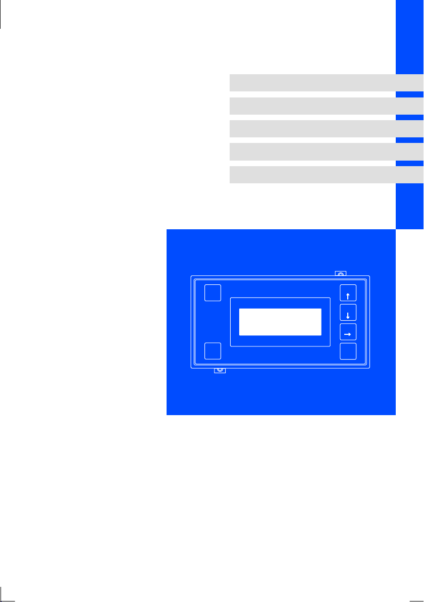
EPM-H312
Bedieneinheit
Operating unit
Unitédecommande
F1
F2
F3
F4
Enter
Page 2

Page 3
Help
Esc
F1
F2
F3
0
shift
1
2
3
4
INPUT: 18 - 32 V 5W
FUSE 315 mA
+24 VDC
0 VDC
NC
Shield
V-
CAN-
1234 5
CAN+
F4
Enter
LCD ADJ
1
ASP8
NC
3
2
h312_002
Page 4

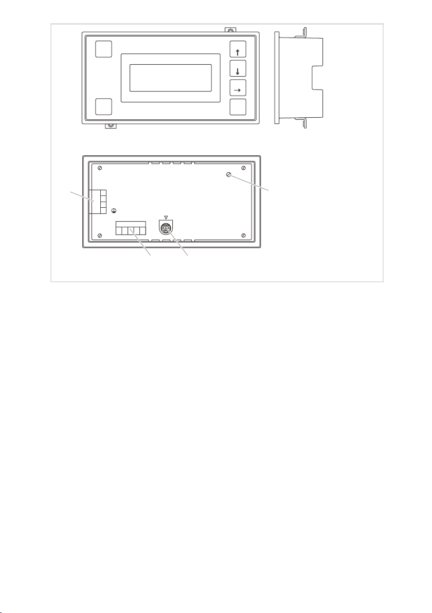
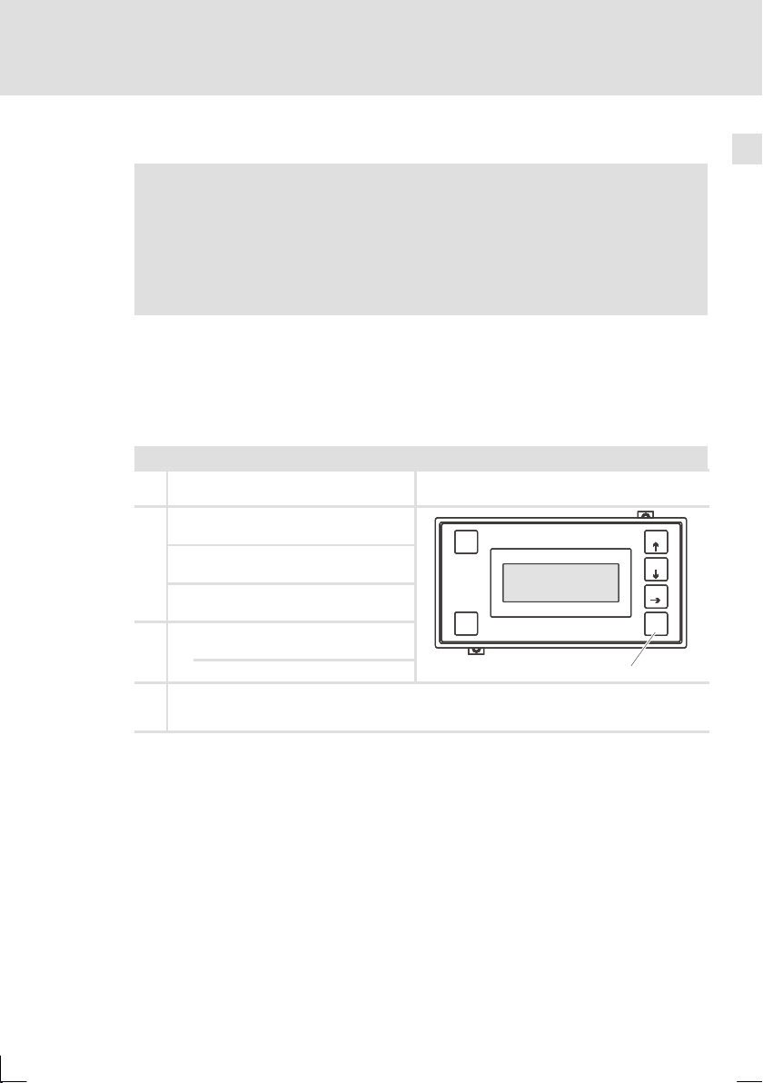
Pos. Beschreibung Funktion
Klemmenleiste 4-polig DC-Spannungsversorgung 24 V
Trimmer LCD ADJ Display-Kontrast einstellen
Minidin-Buchse 8-polig SeriellerPort(ASP)fürPCoderSPS
Klemmenleiste 5-polig Systembus (CAN)
4
EDBPM-H312 DE/EN/FR 2.0
Page 5

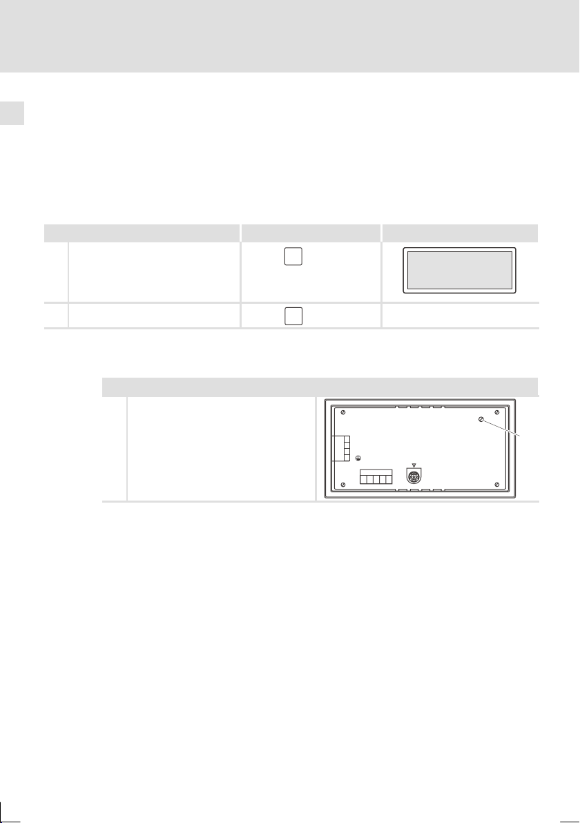
Diese Dokumentation ist gültig für die Bedieneinheit EPM-H312 ab dem Gerätestand
Type EPM - H312 1A 10
Produktreihe
EPM Bedieneinheit
Hardwarestand
Softwarestand
Was ist neu?
Stand ID-Nr. Änderungen
1.0 01/2005 TD 23 13036508 Feldtest
2.0 06/2005 TD 23 13036508 Serienstand
© 2005 Lenze Drive Systems GmbH, Hans-Lenze-Straße 1, D-31855 Aerzen
Ohne besondere schriftliche Genehmigung von Lenze Drive Systems GmbH darf kein Teil dieser Dokumentation vervielfältigt oder Dritten zugänglich gemacht werden.
Wir haben alle Angaben in dieser Dokumentation mit größter Sorgfalt zusammengestellt und auf Übereinstimmung
mit der beschriebenen Hard- und Software geprüft. Trotzdem können wir Abweichungen nicht ganz ausschließen. Wir
übernehmen keine juristische Verantwortung oder Haftung für Schäden, die dadurch eventuell entstehen. Notwendige Korrekturen werden wir in die nachfolgenden Auflagen einarbeiten.
EDBPM-H312 DE/EN/FR 2.0
5
Page 6

Inhalti
1 Vorwort und Allgemeines 8...........................................
1.1 Über diese Betriebsanleitung 8..................................
1.2 Verwendete Begriffe 8.........................................
1.3 Lieferumfang 8...............................................
1.4 Gestaltung der Sicherheitshinweise 9.............................
2 Technische Daten 10..................................................
2.1 Allgemeine Daten / Einsatzbedingungen 10........................
2.2 Elektrische Daten 11............................................
2.2.1 Eigenschaften der Bedieneinheit 12......................
2.2.2 Schnittstellenbeschreibung 14..........................
2.3 Abmessungen 15...............................................
2.4 Einbauausschnitt 15............................................
3 Mechanische Installation 16............................................
3.1 Bedieneinheit befestigen 16.....................................
4 Elektrische Installation 17..............................................
4.1 Belegung der Anschlussklemmen 17...............................
4.2 Systembus (CAN) verdrahten 18..................................
5 Inbetriebnahme 19...................................................
5.1 Erstes Einschalten 19...........................................
5.2 Projekt in die Bedieneinheit übertragen 20.........................
5.2.1 Bedieneinheit und PC verbinden 20......................
5.2.2 Projekt-Download 21..................................
5.2.3 Verbindung zum PC entfernen 21........................
5.3 Statusmeldungen der Bedieneinheit 22............................
5.4 Kontrast einstellen 22...........................................
6 Bedienung 23........................................................
6.1 Tastenfunktionen 23............................................
6.2 Daten eingeben 24.............................................
6.3 Informationsmeldung aufrufen 26................................
6.4 Hilfe aufrufen 26...............................................
7 Fehlersuche und Störungsbeseitigung 27.................................
7.1 Störungsmeldungen 27.........................................
6
EDBPM-H312 DE/EN/FR 2.0
Page 7

Inhalt i
8Wartung 28.........................................................
9 Anhang 29..........................................................
9.1 Chemikalienbeständigkeit 29....................................
9.2 Stichwortverzeichnis 31.........................................
EDBPM-H312 DE/EN/FR 2.0
7
Page 8
1
Bedeeet
3
ÜbepüeSeacatdeeeugsoot,obde
S
chraub
e
3
5
t
immt.F
ü
h
trägl
ichrek
lamierteM
ä
lüb
2SchraubenM4×35mm
nimmtLenzekeineGewährleistung
1Dichtung
er.
p
g
f
rer
1Klemmenleiste5-poligfürAnschluss
erkennbareMängel/Unvollständigkeitsofortbeide
r
Vorwort und Allgemeines
Über diese Betriebsanleitung
1 Vorwort und Allgemeines
Mit der Bedieneinheit EPM-H312 können Sie auf Codestellen von Lenze Antriebsreglernzugreifenunddiese auf komfortableWeise steuern.Die Kommunikation erfolgt über Systembus (CAN).
Mit der Lenze-Software »HMI Designer« lässtsich dieProgrammierungder Bedieneinheit einfach realisieren.
1.1 Über diese Betriebsanleitung
ƒ
Die vorliegende Betriebsanleitung dient dem sicherenund fehlerfreien
Arbeiten an und mit der Bedieneinheit EPM-H312.
ƒ
Alle Personen, die an und m it der Bedieneinheit EPM-H312 arbeiten, müssen
bei ihren Arbeiten die Betriebsanleitung verfügbar haben und die für sie
relevanten Angaben und Hinweise beachten.
ƒ
Die Betriebsanleitung muss stets komplett und in einwandfrei lesbarem
Zustand sein.
1.2 Verwendete Begriffe
Begriff Im folgenden Text verwendet für
Antriebsregler Lenze Freque nzumrichter 8200 vector und 9300 vector,
HMI Human Machine Interface
Lenze Servo-Umrichter 9300 und 9400
1.3 Lieferumfang
Menge Wichtig
1 Bedieneinheit EPM-H312 Überprüfen Sie nach Erhalt der Lieferung sofort, obder
1 Betriebsanleitung
2Befestigungsschellen
2
1 Dichtung
1 Klemmenleiste 4-polig für Anschluss DCSpannungsversorgung
1 Klemmenleiste 5Systembus(CAN)
nM4×
mm
oli
ür Anschluss
8
Lieferumfang mit den Warenbegleitpapieren übereins
nimmt Lenze keine Gewährleistung.
Reklamieren Sie
rnac
erkennbare Transportschäden sofort beim Anliefer
.
erkennbare Mängel/Unvollständigkeit sofort bei der
zuständigen Lenze-Vertretung.
EDBPM-H312 DE/EN/FR 2.0
-
nge
.
er-
Page 9

1.4 Gestaltung der Sicherheitshinweise
Um aufGefahrenundwichtigeInformationen hinzuweisen,werdenin dieser Dokumentation folgende Signalwörter und Symbole verwendet:
Sicherheitshinweise
Aufbau der Sicherheitshinweise:
Gefahr!
(kennzeichnet die Art und die Schwere der Gefahr)
Hinweistext
(beschreibt die Gefahr und gibt Hinweise, wie sie vermieden werden
kann)
Piktogramm und Signalwort Bedeutung
Gefahr!
Gefahr!
Stop!
Anwendungshinweise
Vorwort und Allgemeines
Gestaltung der Sicherheitshinweise
Gefahr von Personenschäden durch gefährliche elektrische Spannung
Hinweis auf eine unmittelbar drohende Gefahr, die den
Tod oder schwere Verletzungen zur Folge habenkann,
wenn nicht die entsprechenden Maßnahmen getroffen
werden.
Gefahr von Personenschäden durch eine allgemeine Gefahrenquelle
Hinweis auf eine unmittelbar drohende Gefahr, die den
Tod oder schwere Verletzungen zur Folge habenkann,
wenn nicht die entsprechenden Maßnahmen getroffen
werden.
Gefahr von Sachschäden
Hinweis auf eine mögliche Gefahr, die Sachschäden zur
Folge haben kann,wenn nicht die entsprechenden Maßnahmen getroffen werden.
1
Piktogramm und Signalwort Bedeutung
X
H
EDBPM-H312 DE/EN/FR 2.0
Hinweis!
Tipp!
Wichtiger Hinweis für die störungsfreie Funktion
Nützlicher Tipp für die einfache Handhabung
Verweis auf andere Dokumentation
9
Page 10

2
Technische Daten
Allgemeine Daten / Einsatzbedingungen
2 Technische Daten
2.1 Allgemeine Daten / Einsatzbedingungen
Bereich Werte
Konformität CE EMV-Richtlinie (89/336/EEC)
Approbation
Angewandte Normen zu
Grenzwerten
Schutzart
Klimatische Bedingungen
Zulässige Temperatur-
bereiche
Transport -20 °C ... +60 °C
Lagerung -20 °C ... +60 °C
Betrieb 0 °C ... +50 °C
Masse 0,5 kg
cULus: in Vorbereitung
Störaussendung nach EN 50081-2 (1994)
Störfestigkeit nach EN 50082-2 (1995)
IP65 (Frontseite)
Feuchte (ohne Betauung) <85 %
10
EDBPM-H312 DE/EN/FR 2.0
Page 11

2.2 Elektrische Daten
Display
ElektrischerA
n
Netzwer
k
Bereich Werte
Display Typ
Sichtbare Größe 70,4 × 20,8 mm
Zeilen 4 Zeilen à 20 Zeichen
Zeichengröße 2,95×4,75mm,Text:5×7Pixel
Fonts ASCII, Katakana
Kontrasteinstellung Trimmpotentiometer
Hintergrundbeleuchtung LED
Elektrischer Anschluss
Netzwerk
Speicher Anwenderprogramm 256 kB
Schnittstellen seriell ASP (Minidin 8 pol.Buchse) RS232
DC-Spannungsversorgung DC 24 V (+18 ... 32 V)
Leistungsaufnahme
Protokoll Systembus (CAN)
Kommunikationsmedium DIN ISO 11898
Netzwerk-Topologie Linie (beidseitig abgeschlossen mit
Technische Daten
Elektrische Daten
LCD
5WbeiDC24V
120 Ω )
2
EDBPM-H312 DE/EN/FR 2.0
11
Page 12

2
Funktione
n
teeBeee
oguatodeutostaste
o
g
Seque
e
6
Set
e
Technische Daten
Elektrische Daten
Eigenschaften der Bedieneinheit
2.2.1 Eigenschaften der Bedieneinheit
Die Bedieneinheit unterstützt die in der Tabelle aufgeführten Eigenschaften.
Beschreibung Wert
Backup/Wiederherstellen
Direktbefehl mit Wert-Struktur Wert setzen
Dynamische Funktionen Textlisten (mit Bit-Gruppen, Einzel-Bits oder
Funktionen
Funktionstasten 4
Interne Befehle
Interne Register 512 Byte
Konfiguration der Funktionstasten
Logik
Meldungen
Passwort Zeichen 8Bit
Redefinierbare Zeichen 7
Sequenzen
Seiten
Sprachen Unterstützte Sprachen 4
Textlisten
Zahlenwerten)
Bit umkehren
Direktbefehl mit Wert-Struktur
Momentan gesetztes Bit
Interner Befehl
Keine
Sequenz
Taste deaktivieren
Projekt beenden
Projektinformationen anzeigen
Sequenzverzeichnis anzeigen
Sprache ändern
Global
Lokal
Automatische Operationen 20
Gleichungen 20
Timer 20
Informationsmeldungen (insgesamt/gleichzei-
tig aktiv)
Hilfe zu Meldungen 128
Beliebig
Start/Stop
Seiten 127
Hilfe zu Seiten 127
1)
1024
128/128
64
12
EDBPM-H312 DE/EN/FR 2.0
Page 13

Variablen
Variablen
12proSeiten
1)
Eigenschaften der Bedieneinheit
Numerische Gleitpunkt-Variablen
Numerische Variablen (DEC, HEX, BIN, BCD)
String-Variablen (ASCII)
von der Projektgröße begrenzter Richtwert
Technische Daten
Elektrische Daten
WertBeschreibung
12 pro Seiten
2
EDBPM-H312 DE/EN/FR 2.0
13
Page 14

2
Technische Daten
Elektrische Daten
Schnittstellenbeschreibung
2.2.2 Schnittstellenbeschreibung
678
5
3
4
12
Abb. 2-1 ASP8 Minidin 8pol. Buchse
Pin Signal
1 Rx RS232 IN
2 Tx RS232 OUT
3 n. c.
4 RTS RS232 OUT
5 CTS RS232 IN
6 n. c.
7 Signal GND
8 +5 VCC (reserved)
n.c. Nicht angeschlossen
h310_010
14
EDBPM-H312 DE/EN/FR 2.0
Page 15
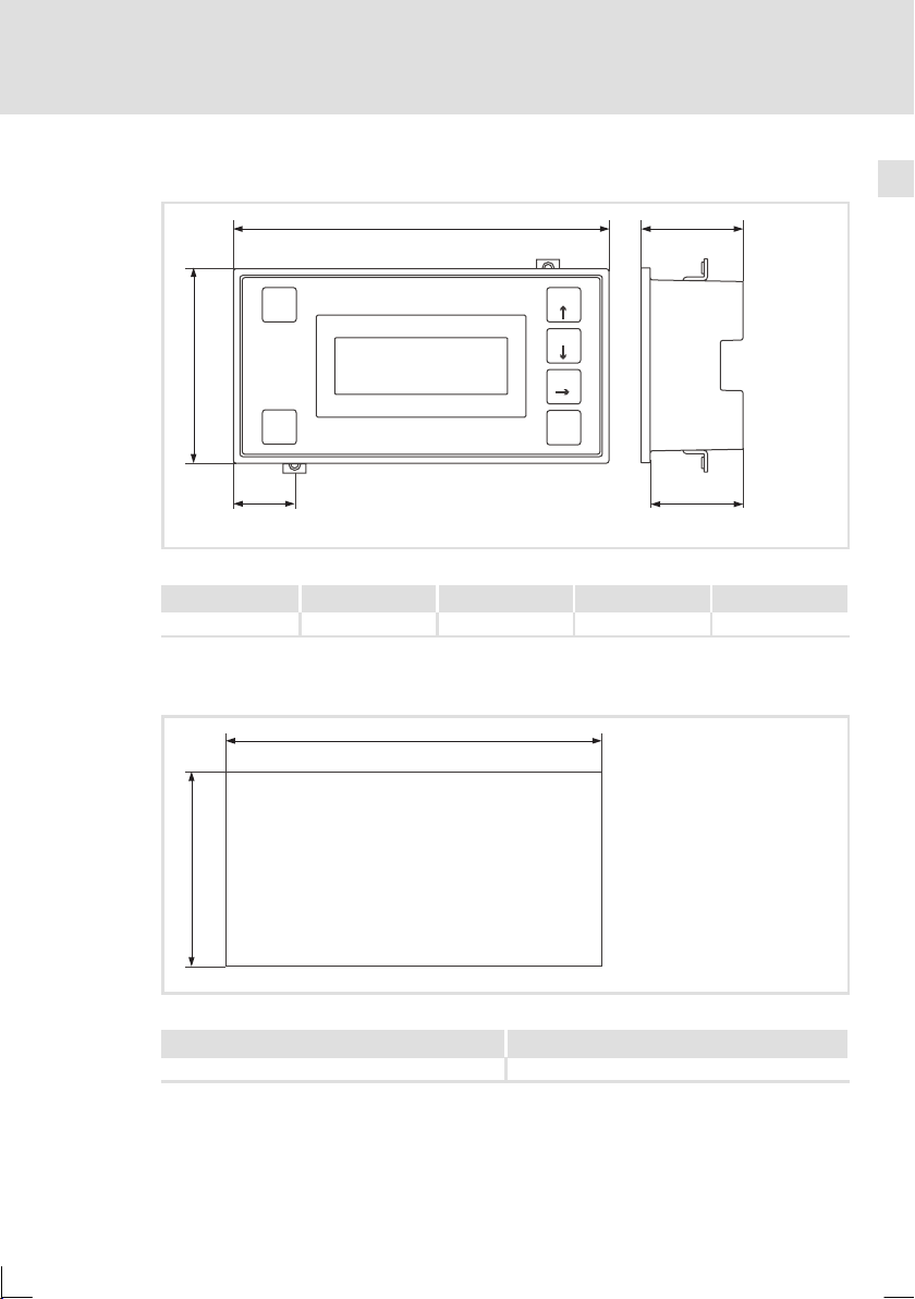
2.3 Abmessungen
Technische Daten
Abmessungen
2
Help
Esc
a
shift
d1
Abb. 2-2 Abmessungen
a [mm] b [mm] d1 [mm] e [mm] e1 [mm]
86,0 166,0 27,0 45,0 41,0
2.4 Einbauausschnitt
b
F1
F2
F3
F4
Enter
b
e
e1
h312_003
a
Abb. 2-3 Einbauausschnitt
EDBPM-H312 DE/EN/FR 2.0
a [mm] b [mm]
77,0 157,0
h312_004
15
Page 16
3
Mechanische Installation
Bedieneinheit befestigen
3 Mechanische Installation
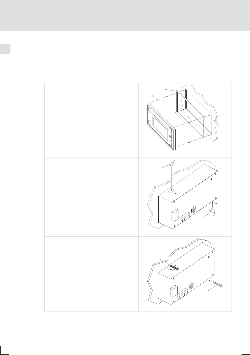
3.1 Bedieneinheit befestigen
Die Maße fürdenEinbauausschnitt entnehmenSieden technischen Daten.(Q 15)
1. Bedieneinheit mit Dichtung in den Einbauausschnitt schieben.
2. Befestigungsschellen in die Öffnungsschlitze der Bedieneinheit schieben.
3. Schrauben gegen die Einbautafel drehen
und festziehen.
1
0
H312_005
2
W
5
V
2
3
-
8
A
m
:1
5
T
1
U
3
P
IN
E
S
U
F
8
P
S
A
C
D
V
4
2
+
1
C
D
0V
N.C.
2
.
.C
CAN+
N
3
Shield
5
CAN-
4
4
V-
3
2
1
3
J
D
A
D
C
L
2
h312_006
J
D
A
D
LC
16
W
5
V
2
3
-
8
A
m
:1
5
T
1
U
3
P
IN
E
S
FU
8
SP
A
C
VD
4
2
+
1
C
D
0V
N.C.
2
.
.C
CAN+
N
3
Shield
5
CAN-
4
4
V-
3
2
1
EDBPM-H312 DE/EN/FR 2.0
3
h312_007
Page 17
4 Elektrische Installation
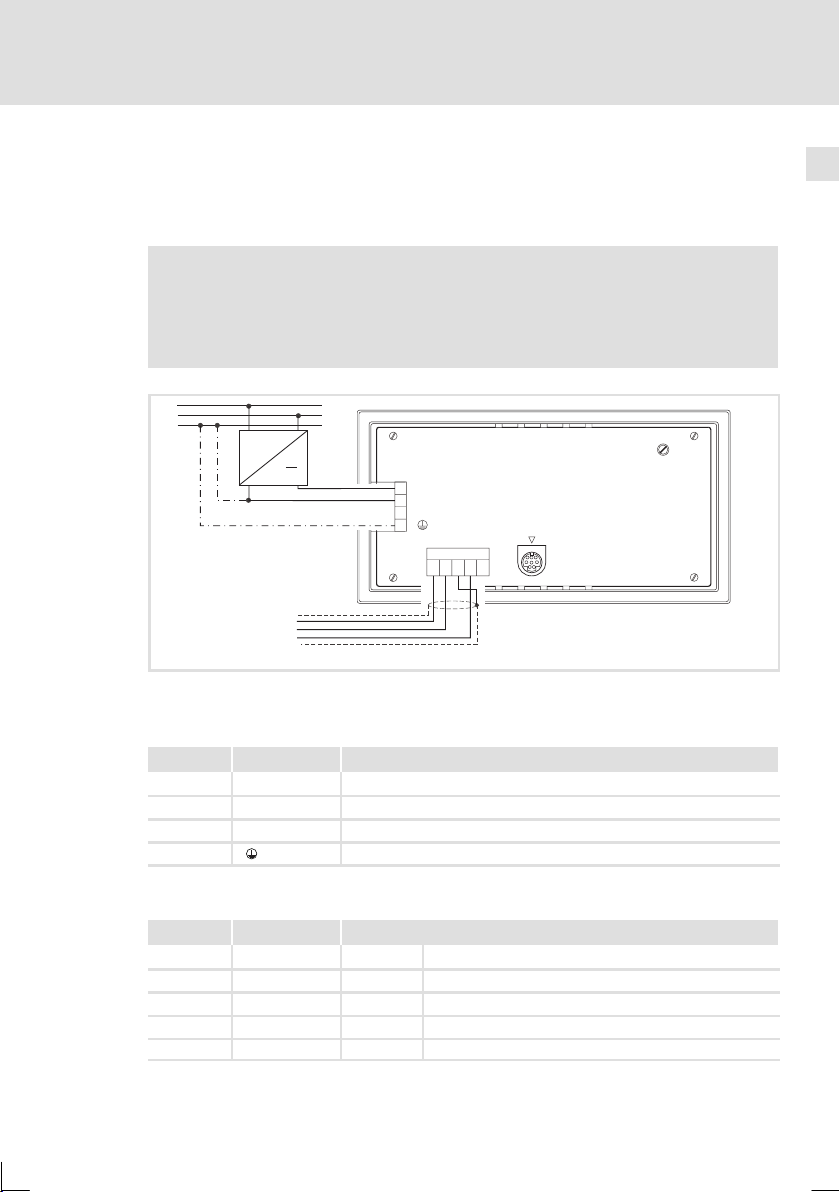
4.1 Belegung der Anschlussklemmen
Stop!
ƒ
Beschädigung angeschlossener Geräte. Verbinden Sie den PE-Leiter
so wie es in der Abbildung dargestellt ist!
ƒ
Bedieneinheit nur im spannungslosen Zustand verdrahten!
L1
N
PE
Abb. 4-1 Belegung der Anschlussklemmen
~
+18…32VDC
CAN-GND
CAN-LO
CAN-HI
Elektrische Installation
Belegung der Anschlussklemmen
INPUT: 18 - 32 V 5W
FUSE 315 mA
1
+24 VDC
2
0VDC
3
N.C.
4
Shield
V-
CAN-
1234 5
CAN+
ASP8
N.C.
4
LCD ADJ
h312_008
DC-Spannungsversorgung
Klemme Bezeichnung Erläuterung
1 DC +24 V Versorgungsspannung (DC +18 V ... 32 V)
2 DC 0 V GND Versorgungsspannung, Bezugspotential
3 n. c. Nicht angeschlossen
4 PE-Potential
Systembus (CAN)
Klemme Bezeichnung Erläuterung
1V- GND Bezugspotential
2 CAN- LO Systembus LOW (Datenleitung)
3 Shield Schirm des Systembus-Kabels auflegen
4 CAN+ HI Systembus HIGH (Datenleitung)
5 n. c. Nicht angeschlossen
EDBPM-H312 DE/EN/FR 2.0
17
Page 18
4
Elektrische Installation
Systembus (CAN) verdrahten
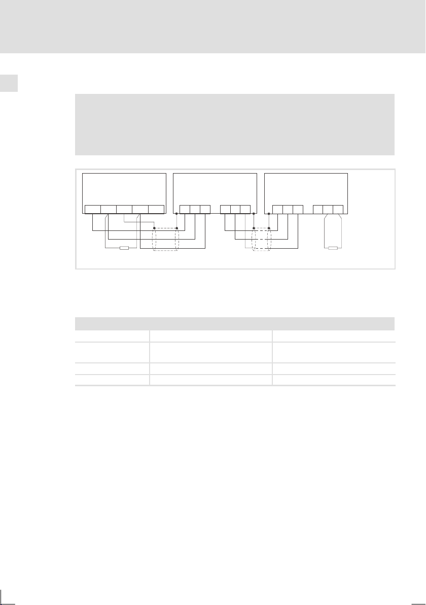
4.2 Systembus (CAN) verdrahten
Hinweis!
ƒ
Verbinden Sie nur Klemmen gleichen Signaltyps miteinander.
ƒ
Weitere Informationen zum Systembus (CAN) finden Sie im
Kommunikationshandbuch CAN.
A
(H312)
1
ShieldCAN--V CAN+ N.C.
120
Abb. 4-2 Verdrahtung des Systembus (CAN)
Busteilnehmer 1 A2Busteilnehmer 2 AnBusteilnehmer n
A
1
CG LO HI
A
2
CG LO HI
A
n
CG LO HI CG LO
HI
120
h312_009
Bitte folgen Sie bei der Verwendung des Signalkabels unseren Empfehlungen:
Spezifikation des Übertragungskabels
Gesamtlänge ≤ 300 m
Kabeltyp LIYCY2x2x0,5mm
(paarverseilt mit Abschirmung)
Leitungswiderstand ≤ 80 Ω/km ≤ 80 Ω/km
Kapazitätsbelag ≤ 130 nF/km ≤ 60 nF/km
2
≤ 1000 m
CYPIMF2x2x0,5mm
(paarverseilt mit Abschirmung)
2
18
EDBPM-H312 DE/EN/FR 2.0
Page 19

5 Inbetriebnahme
5.1 Erstes Einschalten
Für die Inbetriebnahme ist eine vollständige Verdrahtungdes Systembus notwendig.
Überprüfen Sie vor dem Einschalten der Versorgungsspannung ...
ƒ
die gesamte Verdrahtung auf Vollständigkeit und Kurzschluss,
ƒ
ob das Bussystem beim physikalisch ersten und letzten Busteilnehmer
abgeschlossen ist.
Inbetriebnahme
Erstes Einschalten
5
EDBPM-H312 DE/EN/FR 2.0
19
Page 20
5
Inbetriebnahme
Projekt in die Bedieneinheit übertragen
Bedieneinheit und PC verbinden
5.2 Projekt in die Bedieneinheit übertragen
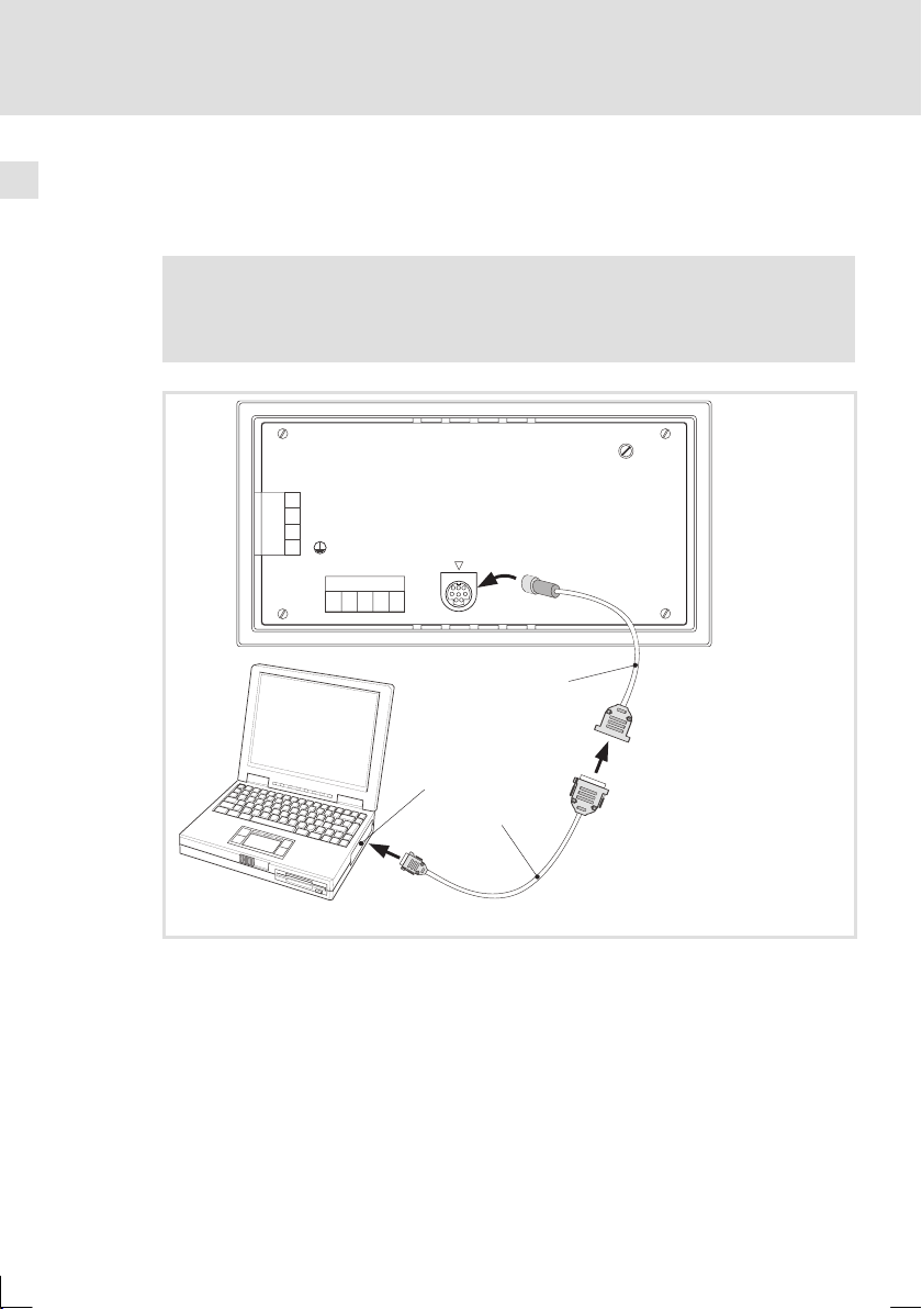
5.2.1 Bedieneinheit und PC verbinden
Stop!
Die Verbindung zwischen PC und Bedieneinheit nur bei ausgeschalteten
Geräten herstellen!
INPUT: 18 - 32 V 5W
FUSE 315 mA
1
+24 VDC
2
0 VDC
3
N.C.
4
V-
CAN-
123 45
Shield
CAN+
ASP8
N.C.
LCD ADJ
0
l
HM
ID
esigner
2
1
Abb. 5-1 Bedieneinheit und PC verbinden
ƒ
Programmieradapter EPZ-H111 an der Bedieneinheit auf die
ASP8-Schnittstelle stecken.
ƒ
Downloadkabel EPZ-H110 mit Programmieradapter EPZ-H111 verbinden.
ƒ
Downloadkabel EPZ-H110 am PC auf COM1 oder COMx stecken.
h312_010
20
EDBPM-H312 DE/EN/FR 2.0
Page 21
5.2.2 Projekt-Download
Hinweis!
Im »HMI Designer« können Sie auswählen, ob mit dem Laden d es
Projekts gleichzeitig die Firmware aktualisiert werden soll.
Die Firmware muss immer beim ersten Download eines Projekts in die
Bedieneinheit bzw. nach einem Update des Projektierungstool
»HMI Designer« aktualisiert werden.
X
Tipp!
Beispiel-Projekte für die Bedieneinheit finden Sie im Projektierungstool
»HMI Designer« unter Datei Öffnen... Samples.
Das müssen Sie tun
PC einschalten und Projektierungstool
A
»HMI Designer« starten.
B Enter-Taste an der Bedieneinheitge-
drückt halten.
Versorgungsspannung für Bedieneinheit
einschalten.
Enter-Taste loslassen, wenn im Display
”H312 Service Page” erscheint.
C Gewünschtes Projekt vom »HMI Designer«
in die Bedieneinheit übertragen.
E
HMI Designer - Erste Schritte
D Nach dem Download ist die Bedieneinheit betriebsbereit und kann über den Systembus mit den
angeschlossenen Teilnehmern Daten austauschen. DasProjekt bleibt nach dem Ausschalten der
Versorgungsspannung gespeichert.
Inbetriebnahme
Projekt in die Bedieneinheit übertragen
Projekt-Download
Help
Help
Help
Help
Help
Esc
Esc
Esc
Esc
Esc
shift
shift
shift
shift
shift
5
F1
F1
F1
F1
F1
F2
F2
F2
F2
F2
F3
F3
F3
F3
F3
F4
F4
F4
F4
F4
Enter
Enter
Enter
Enter
Enter
0
0
0
0
0
5.2.3 Verbindung zum PC entfernen
1. PC ausschalten.
2. Versorgungsspannung für Bedieneinheit abschalten.
3. Programmieradapter EPZ-H111 an der Bedieneinheit und Downloadkabel
EPZ-H110 am PC abziehen.
4. Versorgungsspannung für Bedieneinheit einschalten.
Die Bedieneinheit ist betriebsbereit.
EDBPM-H312 DE/EN/FR 2.0
21
Page 22
5
Inbetriebnahme
Statusmeldungen der Bedieneinheit
5.3 Statusmeldungen der Bedieneinheit
Sie können jederzeit den Status der Bedieneinheit abfragen. Sie erhalten Informationen über:
ƒ
Den Namen des geladenen Treibers (Driver)
ƒ
Die Version des geladenen Treibers (Ver)
ƒ
Die Netzadresse der Bedieneinheit (Addr)
ƒ
Die zuletzt aufgetretene Störung (Error)
Sie möchten ... Berühren Sie die Felder... Beispiel
A ... den Status der Bedieneinheit abfra-
gen.
shift
2×
Driver : CAN Lenze M
Driver : CAN Lenze M
Driver : CAN Lenze M
Ver : 1.12
Ver : 1.12
Ver : 1.12
Addr : NO ADDRESS
Addr : NO ADDRESS
Addr : NO ADDRESS
Error : RESET
Error : RESET
Error : RESET
B ... die Statusanzeige schließen.
5.4 Kontrast einstellen
Das müssen Sie tun
Auf der Rückseite der Bedieneinheit stellen
A
Sie mit dem Trimmer LCD ADJ den Kontrast des Displays ein.
Help
Esc
INPUT: 18- 32 V 5W
FUSE 315 mA
1
+24VDC
2
0VDC
3
NC
4
V-
1234 5
ASP8
Shield
NC
CAN+
CAN-
LCD ADJ
0
22
EDBPM-H312 DE/EN/FR 2.0
Page 23

6 Bedienung
6.1 Tastenfunktionen
Tasten Funktion Erläuterung
F4
F1
shift
+
shift
+
Help
Help
Enter
...
Esc
F1
F2
F3
F4
Enter
Esc
<F1> ... <F4>
<Help>
<Pfeil auf>
<Pfeil ab>
<Pfeil rechts>
<Parameter auswählen>
<Eingabe bestätigen>
<ESC/Help>
Bedienung
Tastenfunktionen
Funktion von F1 ... F4 ausführen (Tasten programmierbar)
Hilfe zu einer Seite bzw. Hilfe zur Informationsmeldung aufrufen
Menüebene: Zur vorherigen Seite wechseln
Parameterebene: Zifferneingabe (0 ... 9 aufsteigend)
Menüebene: Zur nächsten Seite wechseln
Parameterebene: Zifferneingabe (0 ... 9 absteigend)
Menüebene: Cursor in die nächste Zeile stellen
Parameterebene: Cursor auf die nächste Ziffer
stellen
Parameter zum Eingeben eines Wertes anwählen,
Übernehmen des eingegebenen Wertes
Parametereingabe zurücksetzen; Hilfe- bzw. Informationsseite verlassen,
Informationsmeldungen anzeigen
6
EDBPM-H312 DE/EN/FR 2.0
Hinweis!
Die Funktionstasten F1 ... F4 sind über die Software »HMI Designer«
programmierbar.
ƒ
Werkseinstellung: Ohne Funktion.
23
Page 24
6
Bedienung
Daten eingeben
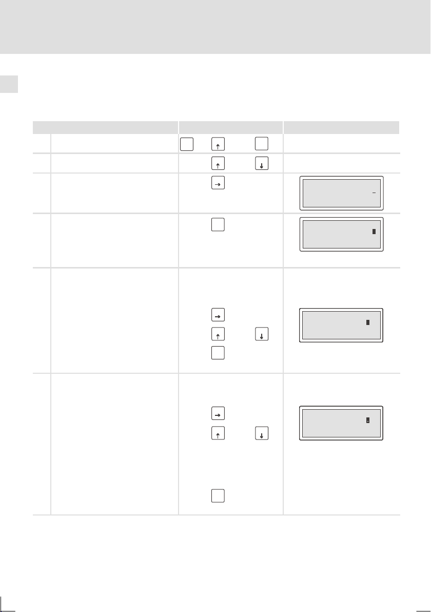
6.2 Daten eingeben
Das Eingeben oder Ändern vonDaten ist Schritt für Schritt dargestellt und wird an
einem Beispiel erläutert.
Sie möchten ... Berühren Sie die Felder... Beispiel
A ... ein Menü anwählen.
B ... eine Seite anwählen.
C ... den Cursor auf das nächste Feld stel-
len.
shift
F1
+
F1
F3
...
oder
F4
Enter
F2
Feld 1 ON
Feld 2 -9876
D ... in die Parameterebene wechseln.
Der Cursor stellt sich auf die rechte
Ziffer
In einem dynamischen Textfeld
stellt sich der Cursor auf das linke
Zeichen (siehe G).
E
... eine einzelne numerische Ziffer ändern.
1. Wechseln Sie in die Parameterebene (siehe D).
2. Wählen Sie die gewünschte Ziffer.
3. Ändern Sie die Ziffer.
4. Bestätigen Sie die Eingabe.
– Der Cursor wechselt in die Menü-
ebene.
F
... ein Komma setzen.
1. Wechseln Sie in die Parameterebene (siehe D).
2. Wählen Sie die Position, an der Sie
das Komma einfügen möchten.
3. Ändern Sie die Ziffer, bis das
Komma erscheint.
Hinweis:
Sie können ein Gleitkomma nur einfügen, wenn das Feld als “Floating Point”
definiert ist (siehe Projektierungstool
»HMI Designer«).
4. Bestätigen Sie die Eingabe.
– Der Cursor wechselt in die Menü-
ebene.
F4
Enter
F3
oder
oder
F2
F2
F1
F4
Enter
F3
F1
F4
Enter
Feld 1 ON
Feld 2 -9876
Feld 1 ON
Feld 1 ON
Feld 1 ON
Feld 2 -9 763
Feld 2 -9 763
Feld 2 -9 763
Feld 1 ON
Feld 1 ON
Feld 1 ON
Feld 2 -9 76
Feld 2 -9 76
Feld 2 -9 76
24
EDBPM-H312 DE/EN/FR 2.0
Page 25

G
... ein dynamisches Textfeld ändern.
1. Wechseln Sie in die Parameterebene (siehe D).
2. Wählen Sie die Position, an der Sie
das Zeichen ändern möchten.
3. Ändern Sie das Zeichen.
4. Bestätigen Sie die Eingabe.
– Der Cursor wechselt in die Menü-
ebene.
Bedienung
6
Daten eingeben
BeispielBerühren Sie die Felder...Sie möchten ...
F3
oder
F2
F1
F4
Enter
Feld 1 FF
Feld 1 FF
Feld 1 FF
Feld 2 -9876
Feld 2 -9876
Feld 2 -9876
O
O
O
EDBPM-H312 DE/EN/FR 2.0
25
Page 26
6
Bedienung
Informationsmeldung aufrufen
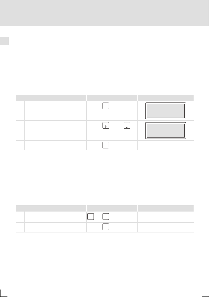
6.3 Informationsmeldung aufrufen
ƒ
Informationsmeldungen
–
sind Texte, die aufgrund eines Ereignisses angezeigt werden (z. B., wenn
ein Istwert eine Grenze übersteigt).
–
können Sie nur aufrufen, solange das auslösende Ereignis vorhanden ist.
–
müssen im Projektierungstool »HMI Designer« programmiert worden sein.
–
können max. 4 Zeilen à 20 Zeichen lang sein.
ƒ
Die Bedieneinheit signalisiert nicht, ob eine Informationsmeldung
vorhanden ist.
Sie möchten ... Berühren Sie die Felder... Beispiel
A ... eine Informationsmeldung aufrufen.
Help
Esc
Druck übersteigt die
Sicherheitsgrenze
B ... die nächsten Informationsmeldun-
gen anwählen.
C ... die Informationsmeldungen schlie-
ßen.
Help
oder
F1
Esc
F2
6.4 Hilfe aufrufen
ƒ
Hilfemeldungen
–
können Seiten- oder Informationsmeldungen zugeordnet sein.
–
enthalten nützliche Hinweise, die die Bedienung erleichtern.
–
müssen im Projektierungstool »HMI Designer« programmiert worden sein.
ƒ
Die Bedieneinheit signalisiert nicht, ob zu einer Seite oder einer
Informationsmeldung eine Hilfemeldung vorhanden ist.
Sie möchten ... Berühren Sie die Felder... Beispiel
A ... eine Hilfemeldung aufrufen.
B ... eine Hilfemeldung schließen.
shift
Help
+
Esc
Help
Esc
Wasserstand unterhalb der
Arbeitsschwelle
26
EDBPM-H312 DE/EN/FR 2.0
Page 27
Fehlersuche und Störungsbeseitigung
i
k
h
lerhaf
ü
f
g
(
gy()p
tembus(CAN)
(
,
(
g
unterbroche
n
derSchnittstelle(Baudrate
gne
r-ErsteSchritte
)
desse,dete)
Störungsmeldungen
7 Fehlersuche und Störungsbeseitigung
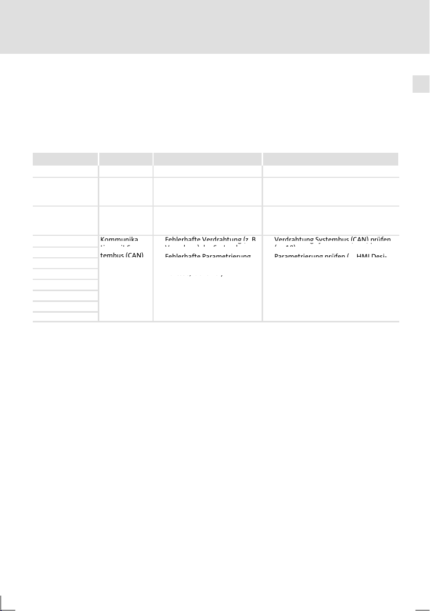
7.1 Störungsmeldungen
Rufen Sie dieStatusmeldungen derBedieneinheit auf,um die zuletztaufgetretene
Störungsmeldung anzuzeigen. (Q 22)
Display Störung Ursache Abhilfe
NO ERROR Keine Störung - -
PR ERROR Fehlerhafter
COM BROK Kommunika-
A-ASIC ko1 Kommun
ASIC ko2
ASIC ko3
ASIC ko4
RESET
SDOERR 6
SDOERR 5
SDOERR 3
Datenaustausch
tion unterbrochen
tion mit Sys-
unterbrochen
Verbindung zwischen Bedieneinheit und PC ist fehlerhaft
Serielles Datenkabel zwischen
Bedieneinheit und PC ist defekt
oder nicht richtig angeschlossen
a-
Fe
te Verdrahtung(z. B.Verdrahtung Systembus(CAN)pr
Verpolung) des Systembus
Fehlerhafte Parametrierung
der Schnittstelle
Adresse, Identifier)
Baudrate
Anschlüsse auf festen Sitz prüfen
Leitung auf Beschädigung kontrollieren
Sub-D-Stecker auf richtigen Anschluss
und festen Sitz prüfen
Serielles Datenkabel austauschen
(E18)
Parametrierung prüfen
,
ner - Erste Schritte).
.
E
HMI Desi-
7
en
EDBPM-H312 DE/EN/FR 2.0
27
Page 28

Wartung8
8Wartung
Die Bedieneinheit ist wartungsfrei, wenn die vorgeschriebenen Einsatzbedingungen eingehalten werden. (Q 10)
ƒ
Reinigen Sie die Bedieneinheit mit denaturiertem Äthylalkohol.
ƒ
Wenn Sie ein anderes Reinigungsmittel verwenden müssen, um
Verunreinigungen zu beseitigen, beachten Sie die Angaben in der Tabelle im
Kap. 9.1. (Q 29)
28
EDBPM-H312 DE/EN/FR 2.0
Page 29

9 Anhang
9.1 Chemikalienbeständigkeit
Stop!
Die Bedien-Oberfläche ist wenig beständig gegen saure
Nahrungsmittel (z. B. Tomatensaft, Zitronensaft). Verschmutzungen
deshalb gleich entfernen, sonst kann die Oberfläche beschädigt
werden.
Die folgende Tabelle zeigt die Beständigkeit der Bedien-Oberfläche (Tastatur,Display, Touch Screen) gegen die genannten Chemikalien.
Für die Bedieneinheiten EPM-H5xx und EPM-H6xx bietet Lenze Schutzfolien an,
mit einer verbesserten Beständigkeit gegen die genannten Chemikalien.
Substanz
Aceton — ☺
Ameisensäure ≥ 50 % — —
Ammoniak ≥ 2% — —
Äthylenglykol —
Ätznatron ≥ 2% — —
Benzin ☺ ☺
Benzol ☺ ☺ ☺
Benzylalkohol — —
Beizlösung konzentriert — — —
Chlorwasserstoffsäure ≥ 10 % — —
Dieselöl ☺ ☺ ☺ ☺
Eisessig — —
Essigsäure ≥ 5%<50% ☺
Ethanol ☺
Hochdruck und Temperatur > 100 °C
Isopropanol ☺ ☺ ☺
Methanol ☺ ☺ —
Methylenchlorid — —
Mineralsäuren konzentriert — —
Natriumhydroxid ≥ 50 % —
Perchlorethylen — — ☺
Anhang
Chemikalienbeständigkeit
Bedieneinheit
EPM-H3xx EPM-H4xx EPM-H5xx
EPM-H6xx
— —
9
mit Schutz-
folie
EDBPM-H312 DE/EN/FR 2.0
29
Page 30

9
Anhang
Chemikalienbeständigkeit
Bedieneinheit
Substanz
Substanz
Phosphorsäure ≥ 30 %
Salpetersäure ≥ 5%<10% ☺
Schwefelsäure ≥ 50 %
Toluol ☺ ☺ ☺
Trichlorethylen — — ☺
Unterchlorigsaures Natron ≥ 20 % — —
Wasserstoffsuperoxyd ≥ 25 % — —
EPM-H3xx EPM-H310, EPM-H312, EPM-H315
EPM-H4xx EPM-H410
EPM-H5xx EPM-H502, EPM-H505, EPM-H507, EPM-H510, EPM-H515, EPM-H520,
EPM-H6xx EPM-H605
☺ Oberfläche ist beständig, keine sichtbare Beschädigung
Oberfläche ist nicht beständig, wird beschädigt
—nichtgetestet
EPM-H521, EPM-H525
EPM-H4xxEPM-H3xx
EPM-H5xx
EPM-H6xx
mit Schutz-
folie
30
EDBPM-H312 DE/EN/FR 2.0
Page 31

9.2 Stichwortverzeichnis
Anhang
Stichwortverzeichnis
9
A
Abmessungen, 15
Anschluss, elektischer, 11
Anschlussklemmen, Belegung, 17
Antriebsregler, 8
Approbation, 10
B
Bedieneinheit
- Daten eingeben, 24
- Eigenschaften, 12
- Funktion der Tasten, 23
- Hilfe aufrufen, 26
- Informationsmeldung aufrufen, 26
- Projekt in die übertragen, 20
- Schnittstellenbeschreibung, 14
- Statusmeldungen, 22
- Verbindung zum PC entfernen, 21
- Verbindung zum PC herstellen, 20
Bedieneinheit befestigen, 16
Bedienung, 23
Begriffsdefinitionen, 8
C
Chemikalienbeständigkeit, 29
D
Daten, eingeben, 24
DC-Spannungsversorgung, 11
Display, 11
- Kontrast einstellen, 22
E
Eigenschaften, 12
Einbauausschnitt, 15
Einsatzbedingungen
-Feuchte,10
- Schutzart, 10
Einschalten, erstes, 19
Elektrische Daten, 11
Elektrische Installation, 17
- Belegung der Anschlussklemmen, 17
Erstes Einschalten, 19
F
Fehlersuche, 27
- Störungsmeldungen, 27
H
Hilfemeldung, 26
Human Machine Interface, 8
I
Inbetriebnahme, 19
- erstes Einschalten, 19
Informationsmeldungen, 26
Installation, Systembus (CAN), 18
Installation, elektrische, 17
Installation, mechanische, 16
EDBPM-H312 DE/EN/FR 2.0
31
Page 32

9
Anhang
Stichwortverzeichnis
K
Kabeltyp, 18
Kapazitätsbelag, 18
Klimatische Bedingungen, 10
Konformität, 10
Kontrast, einstellen, 22
L
Leistungsaufnahme, 11
Leitungswiderstand, 18
M
Masse, 10
Mechanische Installation, 16
P
PC
- Verbindung zur Bedieneinheit entfernen, 21
- Verbindung zur Bedieneinheit herstellen, 20
Projekt, in die Bedieneinheit übertragen, 20
Projekt-Download, 21
S
Schutzart, 10
Sicherheitshinweise, 9
Speicher, 11
Statusmeldungen, 22
Störungsbeseitigung, 27
Störungsmeldungen, 27
Systembus (CAN)
- Kommunikationsmedium, 11
- Verdrahtung, 18
T
Tastenfunktionen, 23
Technische Daten, 10
- Abmessungen, 15
- DC-Spannungsversorgung, 11
-Display,11
- Einbauausschnitt, 15
- Elektrische Daten, 11
- elektrischer Anschluss, 11
- Leistungsaufnahme, 11
- Masse, 10
- Schnittstellenbeschreibung, 14
-Speicher,11
- Systembus (CAN), 11
Temperaturbereiche, 10
- Bemessungsstrom reduzieren, 10
32
W
Wartung, 28
EDBPM-H312 DE/EN/FR 2.0
Page 33

Anhang
Stichwortverzeichnis
9
EDBPM-H312 DE/EN/FR 2.0
33
Page 34

Pos. Description Function
Terminal strip, 4-pole. DC voltage supply 24 V
Trimmer LCD ADJ Setting display contrast
Minidin 8-pole socket ASP serial port for PC or PLC
Terminal strip, 5-pole System bus (CAN)
34
EDBPM-H312 DE/EN/FR 2.0
Page 35

This documentation applies to the operating unit EPM-H312 as of version
Type EPM - H312 1A 10
Product range
EPM Operating unit
Hardware version
Software version
What’s new?
Version ID no. Changes
2.0 06/2005 TD 31 13036508 Series version
© 2005 Lenze Drive Systems GmbH, Hans-Lenze-Straße 1, D-31855 Aerzen
No part of this documentation may be reproduced or made accessible to third parties without written consent by
Lenze Drive Systems GmbH.
All information given in this documentation has been selected carefully and complies with the hardware and software
described. Nevertheless, deviations cannot be ruled out. We do not take any responsibility or liability for damages
which might possibly occur. Necessary corrections will be included in subsequent editions.
EDBPM-H312 DE/EN/FR 2.0
35
Page 36

Contentsi
1 Preface and general information 38.....................................
1.1 About these Operating Instructions 38.............................
1.2 Terminology used 38...........................................
1.3 Scope of supply 38.............................................
1.4 Layout of the safety instructions 39...............................
2 Technical data 40....................................................
2.1 General data/operating conditions 40.............................
2.2 Electrical data 41..............................................
2.2.1 Features of the operating unit 42........................
2.2.2 Interface description 44...............................
2.3 Dimensions 45.................................................
2.4 Mounting cutout 45............................................
3 Mechanical installation 46.............................................
3.1 Attaching operating unit 46......................................
4 Electrical installation 47...............................................
4.1 Assignment of the terminals 47..................................
4.2 Wire system bus (CAN) 48.......................................
5 Commissioning 49...................................................
5.1 First switch-on 49..............................................
5.2 Project transfer to the operating unit 50............................
5.2.1 Connecting operating unit and PC 50.....................
5.2.2 Project download 51...................................
5.2.3 Disconnecting from the PC 51..........................
5.3 Status messages of the operating unit 52..........................
5.4 Contrast setting 52.............................................
6Operation 53........................................................
6.1 Key functions 53...............................................
6.2 Data input 54.................................................
6.3 Calling up information messages 56..............................
6.4 Calling up help messages 56.....................................
7 Troubleshooting and fault elimination 57................................
7.1 Fault messages 57..............................................
36
EDBPM-H312 DE/EN/FR 2.0
Page 37

Contents i
8 Maintenance 58......................................................
9 Appendix 59.........................................................
9.1 Chemical resistance 59.........................................
9.2 Index 61.....................................................
EDBPM-H312 DE/EN/FR 2.0
37
Page 38

1
opeatgut3
teeceptotedeey,cecedateyete
L
yliabilityfordef
ici
2screwsM4×35m
m
claimedsubsequently
1seal
f
y
)
forwarder
1terminalstrip5po
l.forsystembus(CAN)
visibledeficiencies/incompletenessimmediatelyto
Preface and general information
About these Operating Instructions
1 Preface and general information
This EPM-H312 operatingunit enables youto access codes of Lenzecontrollers and
to control them easily. Communication takes places via the system bus (CAN).
Bymeans of the Lenzesoftware»HMI Designer«the programming oftheoperating
unit is easily achieved.
1.1 About these Operating Instructions
ƒ
These Operating Instructions describe safe and trouble-free working on and
with the EPM-H312 operating unit.
ƒ
All persons working on and with the EPM-H312 operating unit must have
these Operating Instructions available and observe all relevant information
and notes.
ƒ
These Operating Instructions must always be kept as a complete document
and in a readable state.
1.2 Terminology used
Term Used in this text for
Drive controller Lenze frequency inverter 8200 vector and 9300 vector, servo inverter
HMI Human Machine Interface
9300 and 9400
1.3 Scope of supply
Quantity Important
1 operating unit EPM-H312 After receipt of the delivery, check immediately whether
1 Operating Instructions
2 mounting clamps
2screwsM4×35mm
1seal
1 4-pole terminal strip for connection of DC
voltage suppl
1terminalstrip5pol.for system bus(CAN
connection
38
the items delivered match the accompanying papers.
enzedoes notacceptan
claimed subsequently.
Claim
visible transport damage immediately to the
orwarder.
visible deficiencies/incompleteness immediately to
your Lenze representative.
.
.
EDBPM-H312 DE/EN/FR 2.0
encies
Page 39

Preface and general information
1.4 Layout of the safety instructions
Thefollowingsignal words and symbols areusedin this documentation to indicate
dangers and important information:
Safety instructions
Structure of safety instructions:
Danger!
(characterises the type and severity of danger)
Note
(describes the danger and gives information about how to prevent
dangerous situations)
Pictograph and signal word Meaning
Danger!
Danger!
Stop!
Application notes
Layout of the safety instructions
Danger of personal injury through dangerous electrical
voltage.
Reference to an imminent danger that may result in
death or serious personal injury if the corresponding
measures are not taken.
Danger of personal injury through a general source of
danger.
Reference to an imminent danger that may result in
death or serious personal injury if the corresponding
measures are not taken.
Danger of property damage.
Referenceto a possible danger that may result in
property damage if the corresponding measures are not
taken.
1
Pictograph and signal word Meaning
X
H
EDBPM-H312 DE/EN/FR 2.0
Note!
Tip!
Important note to ensure trouble-free operation
Useful tip for simple handling
Reference to another documentation
39
Page 40

2
Technical data
General data/operating conditions
2 Technical data
2.1 General data/operating conditions
Field Values
Conformity CE EMCDirective
Approbation
Standards applied to limit
values
Enclosure
Climaticconditions
Maximum temperature
ranges
Transport -20 °C ... +60 °C
Storage -20°C ... +60 °C
Operation 0 °C ... +50 °C
Mass 0.5 kg
cULus: In preparation
Noise emission to EN 50081-2 (1994)
Noise immunity to EN 50082-2 (1995)
IP65 (front)
Humidity (without bedewing) <85 %
40
EDBPM-H312 DE/EN/FR 2.0
Page 41

2.2 Electrical data
Display
Electrica
l
Network
Field Values
Display Type LCD
Electrical
connection
Network Protocol System bus (CAN)
Memory User program 256kb
Interfaces Serial ASP (minidin 8-pole socket) RS232
Technical data
Electrical data
Visible size 70.4 × 20.8 mm
Lines 4 lines at 20 characters each
Character size 2.95×4.75mm,Text:5×7pixel
Fonts ASCII, Katakana
Contrast setting Trimming potentiometer
Backgroundillumination LED
DC voltage supply DC 24 V (+18 ... 32 V)
Power consumption
Communicationmedium DIN ISO 11898
Network topology Line (terminated with 120 Ω)atboth
5WatDC24V
ends
2
EDBPM-H312 DE/EN/FR 2.0
41
Page 42

2
Functions
teacoad
s
Coguatoouctoeys
ogc
Sequece
s
6
Pages
Technical data
Electrical data
Features of the operating unit
2.2.1 Features of the operating unit
The operating unit supports the characteristics described in the table.
Description Value
Backup/restore
Direct command with value
structure
Dynamic functions Text lists (with bit groups, individual bits, or
Functions Invert bit
Function keys 4
Internal commands End project
Internal registers 512 bytes
Configuration of function keys Global
Logic Automatic operations 20
Messages Information messages (total/simultaneously
Password Character 8bits
Redefinable characters 7
Sequences Optional 64
Pages Pages 127
Languages Supported languages 4
Text lists
Set value
numericalvalues)
Direct command with valuestructure
Currentlyset bit
Internal command
None
Sequence
Deactivate key
Displayprojectinformation
Display sequence index
Change language
Local
Equations 20
Timers 20
active)
Help for messages 128
Start/Stop
Help for pages 127
1024
128/128
1)
42
EDBPM-H312 DE/EN/FR 2.0
Page 43

Technical data
Variables
12perpage
s
Features of the operating unit
Variables Numerical floating point variables 12 per pages
Numericalvariables(DEC,HEX,BIN,BCD)
String variables *ASCII)
1)
guide value limited bythe project size
Electrical data
ValueDescription
2
EDBPM-H312 DE/EN/FR 2.0
43
Page 44

2
Technical data
Electrical data
Interface description
2.2.2 Interface description
678
5
3
4
12
Fig.2-1 ASP8 minidin8/pole socket
Pin Signal
1 Rx RS232 IN
2 Tx RS232 OUT
3 n.c.
4 RTS RS232 OUT
5 CTS RS232 IN
6 n.c.
7 Signal GND
8 +5 VCC (reserved)
n.c. not connected
h310_010
44
EDBPM-H312 DE/EN/FR 2.0
Page 45

2.3 Dimensions
Technical data
Dimensions
2
Help
Esc
a
shift
d1
Fig.2-2 Dimensions
a [mm] b [mm] d1 [mm] e [mm] e1 [mm]
86.0 166.0 27.0 45.0 41.0
2.4 Mounting cutout
b
F1
F2
F3
F4
Enter
b
e
e1
h312_003
a
Fig.2-3 Mounting cutout
EDBPM-H312 DE/EN/FR 2.0
a [mm] b [mm]
77.0 157.0
h312_004
45
Page 46

3
Mechanical installation
Attaching operating unit
3 Mechanical installation
3.1 Attaching operating unit
The dimensions for the mounting cutout can be found in the ”Technical data”
(Q 45)
1. Insert operator terminal with gasket into
the mounting cutout.
2. Insert mounting clamps into the slots at the
operating unit.
3. Tighten the screws against the mounting
board.
1
0
H312_005
2
W
5
V
2
3
-
8
A
m
:1
5
T
1
U
3
P
IN
E
S
U
F
8
P
S
A
C
D
V
4
2
+
1
C
D
0V
N.C.
2
.
.C
CAN+
N
3
Shield
5
CAN-
4
4
V-
3
2
1
3
J
D
A
D
C
L
2
H312_006
J
D
A
D
LC
46
W
5
V
2
3
-
8
A
m
:1
5
T
1
U
3
P
IN
E
S
FU
8
SP
A
C
D
V
4
2
+
1
C
0VD
N.C.
2
.
.C
CAN+
N
3
Shield
5
CAN-
4
4
V-
3
2
1
EDBPM-H312 DE/EN/FR 2.0
3
H312_007
Page 47

4 Electrical installation
4.1 Assignment of the terminals
Stop!
ƒ
Damage of units connected. Connect the PE conductor as shown in
the figure!
ƒ
Wire the operating unit only when no voltage is applied!
L1
N
PE
Fig.4-1 Assignment of the terminals
~
+18…32VDC
CAN-GND
CAN-LO
CAN-HI
INPUT: 18 - 32 V 5W
FUSE 315 mA
1
+24 VDC
2
0VDC
3
N.C.
4
Shield
V-
CAN-
1234 5
Electrical installation
Assignment of the terminals
LCD ADJ
ASP8
N.C.
CAN+
4
h312_008
DC supply voltage
Terminal Identification Explanation
1 DC +24 V Supply voltage (DC +18 V ... 32 V)
2 DC 0 V GND supply voltage, reference potential
3 n.c. not connected
4 PE potential
System bus (CAN)
Terminal Identification Explanation
1V- GND Reference potential
2 CAN- LO System bus LOW (data line)
3 Shield Apply shield of the system bus cable
4 CAN+ HI System bus HIGH (data line)
5 n.c. not connected
EDBPM-H312 DE/EN/FR 2.0
47
Page 48

4
Electrical installation
Wire system bus (CAN)
4.2 Wire system bus (CAN)
Note!
ƒ
Only connect terminals of the same signal type.
ƒ
For further information with regard to the system bus (CAN) please
refer to the CAN Communication Manual.
CG LO HI
A
2
CG LO HI
CG LO HI CG LO
A
(H312)
1
ShieldCAN--V CAN+ N.C.
120
Fig.4-2 Wiring of system bus (CAN)
Bus node 1 A2Bus node 2 AnBus node n
A
1
Please observe our recommendations for signal cables:
Specification for the transmission cable
Total length ≤ 300 m
Cable type LIYCY2x2x0.5mm
Cable resistance ≤ 80 Ω/km ≤ 80 Ω/km
Capacitance per unit
length
(twisted in pairs with shield)
≤ 130 nF/km ≤ 60 nF/km
2
≤ 1000 m
CYPIMF2x2x0.5mm
(twisted in pairs with shield)
A
n
HI
120
h312_009
2
48
EDBPM-H312 DE/EN/FR 2.0
Page 49

5 Commissioning
5.1 First switch-on
Commissioning requires a complete wiring of the system bus.
Before switching on the supply voltage, check...
ƒ
the complete wiring for completeness and short circuit,
ƒ
whether the bus system is terminated at the first and last physical node.
Commissioning
First switch-on
5
EDBPM-H312 DE/EN/FR 2.0
49
Page 50

5
Commissioning
Project transfer to the operating unit
Connecting operating unit and PC
5.2 Project transfer to the operating unit
5.2.1 Connecting operating unit and PC
Stop!
Only connect PC and operating unit when the units are switched off!
INPUT: 18 - 32 V 5W
FUSE 315 mA
1
+24 VDC
2
0 VDC
3
N.C.
4
V-
CAN-
123 45
Shield
CAN+
ASP8
N.C.
LCD ADJ
0
l
H
M
I Designer
2
1
Fig.5-1 Connecting operating unit and PC
ƒ
Plug programming adapter EPZ-H111 onto interface ASP8 at operating unit.
ƒ
Connect download cable EPZ-H110 to programming adapter EPZ-H111 .
ƒ
Plug download cable EPZ-H110 onto COM1 or COMx at PC.
h312_010
50
EDBPM-H312 DE/EN/FR 2.0
Page 51

5.2.2 Project download
Note!
In the »HMI Designer«, you can select whether you want to update the
firmware at the time the project is loaded.
Thefirmwaremustalwaysbeupdatedwiththefirstdownloadofa
project to the operating unit or after an update of the »HMI Designer«
planning tool.
X
Tip!
Sample projects for the operating unit can be found in the
»HMI Designer« planning tool under File Open... Samples.
What to do
Switch on the PC and start the »HMI
A
Designer« planning tool.
B Keepthe enter key ofthe operating unit
pressed.
Switch on the supply voltage for the
operating unit.
Let go of the enter key when ”H312
Service Page” appears on the display.
C Transfer the desired project from the »HMI
Designer« into the operating unit.
E
HMI Designer - Getting started”
D After download is completed, the operating unit i s ready for operation andcan exchange data
with the connected nodes bythe system bus. The project is stored afterdisconnection from the
supply voltage.
Commissioning
Project transfer to the operating unit
Project download
Help
Help
Help
Help
Help
Esc
Esc
Esc
Esc
Esc
shift
shift
shift
shift
shift
5
F1
F1
F1
F1
F1
F2
F2
F2
F2
F2
F3
F3
F3
F3
F3
F4
F4
F4
F4
F4
Enter
Enter
Enter
Enter
Enter
0
0
0
0
0
5.2.3 Disconnecting from the PC
1. Switch off PC.
2. Switch off supply voltage for operating unit.
3. Remove programming adapter EPZ-H111 on the operating unit and the
download cable EPZ-H110 from PC.
4. Switch on supply voltage for operating unit.
The operating unit is ready for operation.
EDBPM-H312 DE/EN/FR 2.0
51
Page 52

5
Commissioning
Status messages of the operating unit
5.3 Status messages of the operating unit
You can always query the status of the operating unit and get information about:
ƒ
Thenameoftheloadeddriver
ƒ
The version of the loaded driver (Ver.)
ƒ
The network address of the operating unit (Addr)
ƒ
The last error
If you want to ... Touch the fields... Example
A ...query the status of the operating
unit
shift
2×
Driver : CAN Lenze M
Driver : CAN Lenze M
Driver : CAN Lenze M
Ver : 1.12
Ver : 1.12
Ver : 1.12
Addr : NO ADDRESS
Addr : NO ADDRESS
Addr : NO ADDRESS
Error : RESET
Error : RESET
Error : RESET
B ...close the status display.
5.4 Contrast setting
What to do
Adjust the displaycontrast with the
A
trimmer LCD ADJ at the back of the
operating unit.
Help
Esc
INPUT: 18- 32 V 5W
FUSE 315 mA
1
+24VDC
2
0VDC
3
NC
4
V-
1234 5
ASP8
Shield
NC
CAN+
CAN-
LCD ADJ
0
52
EDBPM-H312 DE/EN/FR 2.0
Page 53

6Operation
6.1 Key functions
Keys Function Explanation
F4
F1
shift
+
Help
shift
+
Esc
F1
F2
F3
F4
Enter
Help
Esc
<F1> ... <F4> Execute function F1 ... F4 (keys programmable)
Enter
...
<Help>
<Up arrow>
<Down arrow>
<Right arrow>
<Select parameter >
<Confirm input>
<ESC/Help>
Operation
Key functions
Call up help for a page or help for an information
message
Menu level: Go to previous page
Parameter level: Input of figures (0 ... 9 ascending)
Menu level: Go to next page
Parameter level: Input of figures (0 ... 9
descending)
Menu level: Place cursor in next line
Parameter level: Place cursor on next digit
Select parameter to enter a value
Accept the entered value
Reset parameter input; exit help or information
page,
show information messages
6
EDBPM-H312 DE/EN/FR 2.0
Note!
ThecontrolkeysF1...F4areprogrammablebymeansofthesoftware
»HMI Designer«.
ƒ
Default setting: Without function.
53
Page 54

6
Operation
Data input
6.2 Data input
Data input and modification are described step-by-step using examples.
If you want to ... touch the fields... Example
A ... select a menu.
B ... select a page
C ... place the cursor on the next field
shift
F1
+
F1
F3
F4
...
Enter
F2
or
Field 1 ON
Field 2 -9876
D ... change to the next parameter level.
The cursor is placed on the right
digit.
In dynamic text fields, the cursor is
placed on the left character (see G).
E
... change an individual numeric digit.
1. Change to the parameter level
(see D).
2. Select the desired digit.
3. Change the digit.
4. Confirm the input.
– The cursor changes to the menu
level.
F
... insert a point.
1. Change to the parameter level
(see D).
2. Select the position where the point
is to be inserted.
3. Change the digit until the point
occurs.
Note:
A floating point can only be inserted if
the field is defined as “Floating Point”
(see planning tool »HMI Designer«).
4. Confirm the input.
– The cursor changes to the menu
level.
F4
Enter
F3
F1
F4
Enter
F3
F1
F4
Enter
F2
or
or
F2
Field 1 ON
Field 2 -9876
Field 1 ON
Field 1 ON
Field 1 ON
Field 2 -9 763
Field 2 -9 763
Field 2 -9 763
Field 1 ON
Field 1 ON
Field 1 ON
Field 2 -9 76
Field 2 -9 76
Field 2 -9 76
54
EDBPM-H312 DE/EN/FR 2.0
Page 55

G
... change a dynamic text field.
1. Change to the parameter level
(see D).
2. Select the position where the
character is to be changed.
3. Change the character.
4. Confirm the input.
– The cursor changes to the menu
level.
Operation
6
Data input
Exampletouch the fields...If you want to ...
F3
F1
F4
Enter
F2
or
Field 1 FF
Field 1 FF
Field 1 FF
Field 2 -9876
Field 2 -9876
Field 2 -9876
O
O
O
EDBPM-H312 DE/EN/FR 2.0
55
Page 56

6
Operation
Calling up information messages
6.3 Calling up information messages
ƒ
Information messages
–
are texts which appear because of a certain event (e.g. if an actual value
exceeds a limit),
–
can only be called up as long as the triggering event is active.
–
must have been programmed in the ”HMI Designer” planning tool.
–
can have a maximum length of 4 lines at 20 characters each.
ƒ
The operating unit does not indicate whether an information message is
available or not.
If you want to ... Touch the fields... Example
A ... call up an information message.
Help
Esc
Pressure exceeds saftey
limit
B ... select the next information
messages.
C ... close the information messages.
Help
or
F1
Esc
F2
6.4 Calling up help messages
ƒ
Help messages
–
can be assigned to page or information messages.
–
contain useful notes to make handling easier.
–
must have been programmed in the ”HMI Designer” planning tool.
ƒ
The operating unit does not indicate whether a help message is available for
a page or an information message.
If you want to ... Touch the fields... Example
A ... call up a help message.
B ... close a help message.
shift
Help
+
Esc
Help
Esc
Water level below working
treshold
56
EDBPM-H312 DE/EN/FR 2.0
Page 57

Troubleshooting and fault elimination
y
)of
)
yg(gpy)
gy(
)
bus(CAN)
f
,
(
g
interruptedinterface(baudrate,address
Designe
r-Gettingstarted)
dete)
7 Troubleshooting and fault elimination
7.1 Fault messages
Call up the status messages ofthe operating unit to indicate the last occurred fault
message. (Q 52)
Display Fault Cause Remedy
NO ERROR No fault - -
PR ERROR Faulty data
COM BROK Communication
A
ASIC ko1 CommunicationFaultywiring(e. g. polarit
ASIC ko2
ASIC ko3
ASIC ko4
RESET
SDOERR 6
SDOERR 5
SDOERR 3
exchange
interrupted
with system
interrupted
Connection between operating
unit and PC is faulty
Serial data cable between
operating unit and PC is
defective or not correctly
connected
the system bus
Faultyparameter setting o
interface(baud rate,address
identifier)
Check connections fortight fit
Check cable for damages
Check correct connection and tight fit
of Sub-D plug
Exchange serial data cable
Checkwiring ofsystembus(CAN
(E48)
Checkparameter setting
Desi
,
Fault m essages
ner - Gettingstarted).
7
E
HMI
.
EDBPM-H312 DE/EN/FR 2.0
57
Page 58

Maintenance8
8Maintenance
The operating unit is maintenance-free if the specified operating conditions are
adhered to. (Q 40)
ƒ
Clean the operating unit with denatured ethyl alcohol.
ƒ
If you must use a different cleaning agent to remove soiling, observe the
informationinthetableinCh.9.1.(Q 59)
58
EDBPM-H312 DE/EN/FR 2.0
Page 59

9 Appendix
9.1 Chemical r esistance
Stop!
Theresistanceofthesurfaceagainstacidfood(e.g.tomatojuice,
lemon juice) is low. For this reason remove soilings immediately,
otherwise the surface may be damaged.
The following table shows the resistance of the surfaces (keypad, display, touch
screen) to the listed chemicals.
For the operatingunits EPM-H5xx andEPM-H6xx, Lenze offersprotective foilswith
an improved resistance against the listed chemicals.
Substance
Acetic acid ≥ 5%<50% ☺
Acetone — ☺
Ammonia ≥ 2% — —
Benzene ☺ ☺
Benzole ☺ ☺ ☺
Benzyl alcohol — —
Diesel oil ☺ ☺ ☺ ☺
Ethanol ☺
Ethylene glycol —
Formic acid ≥ 50 % — —
High-pressure and
temperature > 100 °C
Hydrochloric acid ≥ 10 % — —
Hydrogen peroxide ≥ 25 % — —
Hypochlorous acidic
natron
Isopropanol ☺ ☺ ☺
Methanol ☺ ☺ —
Methylene chloride — —
Mineral acids Concentrated — —
Nitric acid ≥ 5%<10% ☺
Perchloroethylene — — ☺
Appendix
Chemical resistance
Operating unit
EPM-H3xx EPM-H4xx EPM-H5xx
EPM-H6xx
— —
≥ 20 % — —
with
protective
9
foil
EDBPM-H312 DE/EN/FR 2.0
59
Page 60

9
Appendix
Chemical resistance
Operating unit
EPM-H4xxEPM-H3xx
Substance
Substance
Phosphoric acid ≥ 30 %
Pickling solution Concentrated — — —
Pure acetic acid — —
Sodium hydroxide ≥ 2% — —
Sodium hydroxide ≥ 50 % —
Sulphuric acid ≥ 50 %
Toluol ☺ ☺ ☺
Trichloroethylene — — ☺
EPM-H3xx EPM-H310, EPM-H312, EPM-H315
EPM-H4xx EPM-H410
EPM-H5xx EPM-H502, EPM-H505, EPM-H507, EPM-H510, EPM-H515, EPM-H520,
EPM-H6xx EPM-H605
☺ Surface resists, no visible damage
Surface does not resist, visible damage
—Nottested
EPM-H521, EPM-H525
EPM-H5xx
EPM-H6xx
with
protective
foil
60
EDBPM-H312 DE/EN/FR 2.0
Page 61

9.2 Index
Appendix
Index
9
A
Approbation, 40
Attaching operating unit, 46
C
Cable resistance, 48
Cable type, 48
Capacitance per unit length, 48
Chemical resistance, 59
Climatic conditions, 40
Commissioning, 49
- First switch-on, 49
Conformity, 40
Connection, electrical, 41
Contrast, setting, 52
D
Data, input, 54
DC voltage supply, 41
Definitions, 38
Dimensions, 45
Display, 41
- contrast setting, 52
Drive controller, 38
E
Electrical data, 41
Electrical installation, 47
- assignment of the terminals, 47
Enclosure, 40
F
Fault messages, 57
First switch-on, 49
H
Help messages, 56
Human Machine Interface, 38
I
Index, 61
Information messages, 56
Installation, system bus (CAN), 48
Installation, electrical, 47
Installation, mechanical, 46
K
Key f unctions, 53
L
Layout of the safety instructions, 39
M
Maintenance, 58
Mass, 40
Mechanicalinstallation, 46
Memory, 41
Mounting cutout, 45
EDBPM-H312 DE/EN/FR 2.0
61
Page 62

9
Appendix
Index
O
Operating conditions, Enclosure, 40
Operating unit
- Calling up help messages, 56
- Calling up information messages, 56
- Connecting with the PC, 50
- Data input, 54
- Disconnecting from the PC, 51
- Interface description, 44
- Key functions, 53
- Parameters, 42
-Projecttransfer,50
- Status messages, 52
Operation, 53
P
Parameters, 42
PC
- Connecting with the operating unit, 50
- Disconnecting from the operating unit, 51
Power consumption, 41
Project
- download, 51
- Project transfer to the operating unit, 50
S
Service conditions, Humidity, 40
Statusmessages, 52
Switch on, First, 49
System bus (CAN)
- communication medium, 41
- wiring, 48
T
Technical data, 40
- DC voltage supply, 41
- Dimensions, 45
-display,41
- electrical connection, 41
- electrical data, 41
- interface description, 44
- mass, 40
-memory,41
- mounting cutout, 45
- power consumption, 41
- system bus (CAN), 41
Temperature ranges, 40
- Reduce rated current, 40
Terminals, assignment, 47
Troubleshooting, fault messages, 57
Troubleshooting and fault elimination, 57
62
EDBPM-H312 DE/EN/FR 2.0
Page 63

Appendix
Index
9
EDBPM-H312 DE/EN/FR 2.0
63
Page 64

Pos. Description Fonction
Bornier à 4 bornes Alimentation 24 V CC
Trimmer LCD ADJ Réglage du contraste
Prise Minidin à 8 broches Port série ASP pour PC ou API
Bornier à 5 bornes Bus Système CAN
64
EDBPM-H312 DE/EN/FR 2.0
Page 65

Le présent document s’applique à l’unité de commande EPM-H312 à partir de la version suivante :
Type EPM - H312 1A 10
Série d’appareils
EPM Unité de commande
Version matérielle
Version logicielle
Nouveautés
Edition N° d’ident. Modifications
2.0 06/2005 TD 10 13036508 Version série
© 2005 Lenze Drive Systems GmbH, Hans-Lenze-Straße 1, D-31855 Aerzen
Toute représentation ou reproduction, en tout ou en partie et par quelque procédé que ce soit, est illicite sans
l’autorisation écrite préalable de LenzeDrive Systems GmbH.
Les données figurant dans le présent fascicule ont été établies avec le plus grand soin et leur conformité avec le
matériel et le logiciel décrits a été vérifiée. Des divergences ne peuvent toutefois pas être totalement exclues. Nous ne
saurions être tenus responsables pour tout dommage qui pourrait éventuellement en découler. Les corrections
nécessaires seront intégrées dans les éditions suivantes.
EDBPM-H312 DE/EN/FR 2.0
65
Page 66

Sommairei
1 Av ant-propos et généralités 68.........................................
1.1 Comment utiliser ces instructions de mise en service 68..............
1.2 Terminologie 68...............................................
1.3 Equipement livré 68............................................
1.4 Présentation des consignes de sécurité 69..........................
2 Spécifications techniques 70...........................................
2.1 Caractéristiques générales/conditions d’utilisation 70................
2.2 Caractéristiques électriques 71...................................
2.2.1 Caractéristiques de l’unité de commande 72...............
2.2.2 Affectation de la prise 74...............................
2.3 Encombrements 75.............................................
2.4 Encoche de montage 75.........................................
3 Installation mécanique 76.............................................
3.1 Montage de l’unité de commande 76..............................
4 Installation électrique 77..............................................
4.1 Affectation des bornes de raccordement 77.........................
4.2 Câblage du Bus Système CAN 78..................................
5Miseenservice 79....................................................
5.1 Premièremiseenservice 79......................................
5.2 Transférer le projet dans l’unité de commande 80....................
5.2.1 Relier l’unité de commande et le PC 80...................
5.2.2 Téléchargerun projet 81...............................
5.2.3 Déconnecter le PC 81..................................
5.3 Messages d’état sur l’unité de commande 82.......................
5.4 Réglage du contraste 82.........................................
6 Pilotage 83..........................................................
6.1 Fonction des touches 83.........................................
6.2 Entrer des données 84..........................................
6.3 Appeler un message d’information 86.............................
6.4 Appeler le message d’aide 86.....................................
7 Détection et élimination des défauts 87..................................
7.1 Messages de défaut 87..........................................
66
EDBPM-H312 DE/EN/FR 2.0
Page 67

Sommaire i
8 Maintenance 88......................................................
9 Annexe 89..........................................................
9.1 Résistance aux produits chimiques 89.............................
9.2 Index 91.....................................................
EDBPM-H312 DE/EN/FR 2.0
67
Page 68

1
s
e
c
e
pqq
p
p
service
pourraêtreformuléeultérieuremen
t
p
;
1
joint
réclamationimmédiateauprèsdutransporteu
r
1bornierà4bornespourleraccordementà
pp/qp
p
t
concernée
Avant-propos et généralités
Comment utiliser ces instructions de mise en service
1 Avant-propos et généralités
L’unité de commande EPM-H312 permet d’accéder aux codes des variateurs de
vitesse Lenze et de commander ces appareils defaçonconviviale.Lacommunication
est réalisée via Bus Système CAN.
Le logiciel ”HMI Designer” de Lenze vous permet de réaliser une programmation
aisée de l’unité de commande.
1.1 Comment utiliser ces instructions d e mise en service
ƒ
Les présentes instructions de mise en service permettent d’utiliser en toute
sécurité l’unité de commande EPM-H312.
ƒ
Toute personne utilisant les unités de commande EPM-H312 doit pouvoir
consulter ces instructions à tout instant et est tenue de respecter les
indications et consignes correspondantes.
ƒ
Le document des instructions de mise en service doit être complet et lisible,
en toute circonstance.
1.2 Terminologie
Terme Utilisé dans le présent document pour désigner
Variateur de vitesse les convertisseurs de fréquence 8200 vector et 9300 vector, et les
HMI une interface homme-machine (Human Machine Interface)
servovariateurs 9300 et 9400 de Lenze
1.3 Equipement livré
Quantité IMPORTANT
1 unité de commande EPM-H312
1 document ”Instructions de mise en
rvi
”
2 colliers de fixation
2visM4×35mm
1 bornier à 4 bornes pour le raccordement à
l’alimentation CC
1bornierà5bornes pourle raccordemen
au Bus Système CAN
68
Vérifier à la réception que l’équipement livré est
conformeau bon de livraison. Aucune réclamation ne
ourra êtreformuléeultérieurement.
En cas de
dégâts visibles occasionnés par le transport :
réclamation immédiate au
vices apparents/équipement incomplet :
réclamation immédiate auprès de l’agence Lenze
concernée.
.
rès du transporteur
EDBPM-H312 DE/EN/FR 2.0
.
;
Page 69

Avant-propos et généralités
Présentation des consignes de sécurité
1.4 Présentation des consignes de sécurité
Pour indiquer d es risques et des informations importantes, la présente
documentation utilise les mots et symboles suivants :
Consignes de sécurité
Présentationdes consignes de sécurité
Danger !
(Lepictogrammeindiqueletypederisque.)
Explication
(L’explication décrit le risque et les moyens de l’éviter.)
Pictogramme et mot associé Explication
Situation dangereuse pour les personnes en raison d’une
tension électrique élevée
Danger !
Danger !
Stop !
Consignes d’utilisation
Indication d’un danger imminent qui peut avoir pour
conséquencesdesblessuresmortellesoutrèsgravesen
cas de non-respect des consignesde sécurité
correspondantes
Situation dangereuse pour les personnes en raison d’un
danger d’ordre général
Indication d’un danger imminent qui peut avoir pour
conséquencesdesblessuresmortellesoutrèsgravesen
cas de non-respect des consignesde sécurité
correspondantes
Risquesdedégâtsmatériels
Indication d’un risque potentiel qui peut avoirpour
conséquencesdes dégâts matériels en cas de non-respect
des consignes de sécurité correspondantes
1
Pictogramme et mot associé Explication
X
H
EDBPM-H312 DE/EN/FR 2.0
Remarque
importante !
Conseil !
Remarque importante pourassurerun fonctionnement
correct
Conseil utile pour faciliter la mise en oeuvre
Référence à une autre documentation
69
Page 70

2
Spécifications techniques
Caractéristiques générales/conditions d’utilisation
2 Spécifications techniques
2.1 Caractéristiques générales/conditions d’utilisation
Domaine Données
Conformité CE Directive CEM (89/336/CEE)
Homologation
Normes appliquées pour
les valeurs limites
Indice de protection
Humidité admissible
Plages de température
admissibles
Transport -20 °C ... +60 °C
Stockage -20 °C ... +60 °C
Fonctionnement 0 °C ... +50 °C
Poids 0,5 kg
cULus : en préparation
Perturbations radioélectriques : émission, selon EN 50081-2 (1994)
Protection contre les parasites selon EN 50082-2 (1995)
IP65 (face avant)
<85%,sanscondensation
70
EDBPM-H312 DE/EN/FR 2.0
Page 71

2.2 Caractéristiques électriques
Ecran
Raccordemen
t
Résea
u
Domaine Données
Ecran Type
Taille d’affichage 70,4 × 20,8 mm
Lignes 4 lignes à 20 caractères
Taille de caractère 2,95×4,75mm,texte:5×7pixel
Polices ASCII, Katakana
Réglage du contraste Potentiomètre-trimmer
Rétro-éclairage LED
Raccordement
électrique
Réseau
Mémoire Programme utilisateur 256 kO
Interfaces ASP8 série (prise Minidin à 8 broches) RS232
Alimentation CC 24 V CC (+18 ... 32 V)
Puissance absorbée
Protocole Bus Système CAN
Support de communication DIN ISO 11898
Topologie du réseau Ligne (fermée des deux extrémités avec
Spécifications techniques
Caractéristiques électriques
LCD
5Wpour24VCC
120 Ω )
2
EDBPM-H312 DE/EN/FR 2.0
71
Page 72

2
Fonctions
stuctostees
Coguatodestoucesd
e
ogque
Séquece
s
6
Pages
Spécifications techniques
Caractéristiques électriques
Caractéristiques de l’unité de commande
2.2.1 Caractéristiques de l’unité de commande
L’unité de commande propose les caractéristiques figurant dans le tableau.
Description Valeur
Sauvegarde/reconstitution
Instruction directe avec structure
valeur
Fonctions dynamiques Listes de textes (avec cordon de bits, bit
Fonctions
Touches de fonction 4
Instructions internes
Registre interne 512 octets
Configuration des touches de
fonction
Logique
Messages
Mot de passe Caractères 8bits
Caractères redéfinissables 7
Séquences
Pages
Langues Langues proposées 4
Listes de textes
Activer valeur
individuel ou valeur)
Inversion bit
Instruction directe avec structure valeur
Bit activé actuellement
Instruction interne
Sans fonction
Séquence
Désactiver touche
Fermer projet
Afficher informations projet
Afficher répertoire séquence
Choix de la langue
Configuration globale
Configuration locale
Opérations automatiques 20
Equations 20
Temporisateur 20
Messages d’information (total/activés
simultanément)
Aides aux messages 128
Au choix
Marche/arrêt
Pages 127
Pages d’aide 127
1)
1024
128/128
64
72
EDBPM-H312 DE/EN/FR 2.0
Page 73

Variables
Variables
12parpage
1)
Spécifications techniques
Caractéristiques électriques
Caractéristiques de l’unité de commande
Variables numériques à virgule flottante
Variables numériques (DEC, HEX, BIN, BCD)
Variables String (ASCII)
Valeur approximative limitée par la grandeur process
2
ValeurDescription
12 par page
EDBPM-H312 DE/EN/FR 2.0
73
Page 74

2
Spécifications techniques
Caractéristiques électriques
Affectation de la prise
2.2.2 Affectation de la prise
678
5
3
4
12
Fig.2-1 Prise ASP8 Minidin à 8 broches
Pin Signal
1 Rx RS232 IN
2 Tx RS232 OUT
3 N.C.
4 RTS RS232 OUT
5 CTS RS232 IN
6 N.C.
7 Signal GND
8 +5 VCC (réservé)
N.C. Non connecté
h310_010
74
EDBPM-H312 DE/EN/FR 2.0
Page 75

2.3 Encombrements
Spécifications techniques
Encombrements
2
Help
Esc
a
shift
d1
Fig.2-2 Encombrements
a [mm] b [mm] d1 [mm] e [mm] e1 [mm]
86,0 166,0 27,0 45,0 41,0
2.4 Encoche de montage
b
F1
F2
F3
F4
Enter
b
e
e1
h312_003
a
Fig.2-3 Encoche de montage
EDBPM-H312 DE/EN/FR 2.0
a [mm] b [mm]
77,0 157,0
h312_004
75
Page 76

3
Installation mécanique
Montage de l’unité de commande
3 Installation mécanique
3.1 Montage de l’unité de commande
Pourlescotesdel’encochedemontage,sereporterauchapitreSpécifications
techniques. (Q 75)
1. Glisser l’unité de commande avec joint
dans l’encoche de montage.
2. Placer les colliers de fixation dans les
ouvertures prévues à cet effet.
3. Visserlaplaquedemontageàl’aidedesvis.
1
0
H312_005
2
W
5
V
2
3
-
8
A
m
:1
5
T
1
U
3
P
IN
E
S
U
F
8
P
S
A
C
D
V
4
2
+
1
C
D
0V
N.C.
2
.
.C
CAN+
N
3
Shield
5
CAN-
4
4
V-
3
2
1
3
J
D
A
D
C
L
2
h312_006
J
D
A
D
LC
76
W
5
V
2
3
-
8
A
m
:1
5
T
1
U
3
P
IN
E
S
FU
8
SP
A
C
D
V
4
2
+
1
C
0VD
N.C.
2
.
.C
CAN+
N
3
Shield
5
CAN-
4
4
V-
3
2
1
EDBPM-H312 DE/EN/FR 2.0
3
h312_007
Page 77

Affectation des bornes de raccordement
4 Installation électrique
4.1 Affectation des bornes de raccordement
Stop !
ƒ
Endommagement des appareils connectés. Relier le conducteur PE
uniquement comme indiqué sur l’illustration !
ƒ
Ne procéder au câblage de l’unité de commande qu’en absence de
tension !
L1
N
PE
~
+18…32VDC
INPUT: 18 - 32 V 5W
FUSE 315 mA
1
+24 VDC
2
0VDC
3
N.C.
4
V-
1234 5
Installation électrique
LCD ADJ
CAN+
ASP8
N.C.
CAN-
Shield
4
Fig.4-1 Affectation des bornes
Alimentation CC
Borne Désignation Explication
1 DC +24 V Tension d’alimentation (+18 V ... 32 V CC)
2 DC 0 V GND tension d’alimentation, potentiel de référence
3 N.C. Non connecté
4 Potentiel PE
Bus Système CAN
Borne Désignation Explication
1V- GND Potentiel de référence
2 CAN- LO Bus Système LOW (BAS) (ligne de données)
3 Shield Raccorder le blindage du câble Bus Système.
4 CAN+ HI Bus Système HIGH (HAUT) (ligne de données)
5 N.C. Non connecté
EDBPM-H312 DE/EN/FR 2.0
CAN-GND
CAN-LO
CAN-HI
h312_008
77
Page 78

4
Installation électrique
Câblage du Bus Système CAN
4.2 Câblage du Bus Système CAN
Remarque importante !
ƒ
Ne relier que des bornes du même type.
ƒ
Pour plus de détails concernant le Bus Système CAN, se reporter au
manuel de communication CAN.
A
(H312)
1
ShieldCAN--V CAN+ N.C.
120
Fig.4-2 Câblage du Bus Système CAN
Participant au bus 1 A2Participant au bus 2 AnParticipant au bus n
A
1
CG LO HI
A
2
CG LO HI
A
n
CG LO HI CG LO
HI
120
h312_009
Suivre les recommandations ci-dessous pour la sélection du câble de transmission
des signaux :
Spécification du câble de transmission
Longueur totale ≤ 300 m
Type de câble LIYCY2x2x0,5mm
torsadé par paire avec blindage
Résistance de câble ≤ 80 Ω/km ≤ 80 Ω/km
Capacité de câble ≤ 130 nF/km ≤ 60 nF/km
2
≤ 1000 m
CYPIMF2x2x0,5mm
torsadé par paire avec blindage
2
78
EDBPM-H312 DE/EN/FR 2.0
Page 79

5Miseenservice
5.1 Premièremiseenservice
Pour la mise en service, il est impératif que le Bus Système soit correctement
raccordé.
Avant la mise sous tension, vérifier ...
ƒ
le câblage dans son intégralité pour éviter un court-circuit,
ƒ
si des résistances d’extrémité de bus sont raccordées au premier et au dernier
participant au bus.
Mise en service
Première mise en service
5
EDBPM-H312 DE/EN/FR 2.0
79
Page 80

5
Mise en service
Transférer le projet dans l’unité de commande
Relier l’unité de commande et le PC
5.2 Transférer le projet dans l’unité de commande
5.2.1 Relier l’unité de commande et le PC
Stop !
Ne relier le PC et l’unité de commande qu’en absence de tension!
INPUT: 18 - 32 V 5W
FUSE 315 mA
1
+24 VDC
2
0 VDC
3
N.C.
4
V-
CAN-
123 45
Shield
CAN+
ASP8
N.C.
LCD ADJ
0
l
H
M
I Designer
2
1
Fig.5-1 Relierl’unité de commande et le PC
ƒ
Enficher l’adaptateur de paramétrage EPZ-H111 dans le port ASP8 de l’unité
de commande.
ƒ
Relier le câble de téléchargement EPZ-H110 avec l’adaptateur EPZ-H111 .
ƒ
Enficher le câble de téléchargement EPZ-H110 dans le port COM1 ou COMx
du PC.
h312_010
80
EDBPM-H312 DE/EN/FR 2.0
Page 81

5.2.2 Télécharger un projet
Remarque importante !
L’outil de conception ”HMI Designer” vous permet de déterminer si,
simultanément au chargement du projet, le Firmware doit être
actualisé.
Il faut toujours procéder à l’actualisation du Firmware lors du premier
téléchargement d’un projet dans l’unité de commande, et après une
mise à jour de l’outil de conception ”HMI Designer”.
X
Conseil !
Pour les exemples de projet de l’unité de commande,voir l’outil de
conception ”HMI Designer” Fichier Ouvrir... Samples (exemples).
Ce qu’il faut faire
MettrelePCsoustensionetdémarrer
A
l’outil de conception ”HMI Designer”.
B Appuyer, sans relâcher,sur la touche
”Enter” de l’unité decommande.
Mettre l’unité de commande sous tension.
Relâcher la touche ”Enter” dès que
l’affichage ”H312 Service Page” apparaît.
C Chargerleprojetsouhaitédel’HMI
Designer dans l’unité de commande.
E
”HMI Designer - Premières étapes”
D Après téléchargement, l’unité de commande est prête à fonctionner et peut échanger des
données via l e Bus Système avec les participants au bus. Le projet est gardé en mémoire après la
mise hors tension.
Mise en service
Transférer le projet dans l’unité de commande
Télécharger un projet
Help
Help
Help
Help
Help
Esc
Esc
Esc
Esc
Esc
shift
shift
shift
shift
shift
5
F1
F1
F1
F1
F1
F2
F2
F2
F2
F2
F3
F3
F3
F3
F3
F4
F4
F4
F4
F4
Enter
Enter
Enter
Enter
Enter
0
0
0
0
0
5.2.3 Déconnecter le PC
1. MettrelePChorstension.
2. Mettre l’unité de commande hors tension.
3. Retirerl’adaptateurEPZ-H111del’unitédecommandeetlecâblede
téléchargement EPZ-H110 du PC.
4. Mettre l’unité de commande sous tension.
L’unité de commande est prête à fonctionner.
EDBPM-H312 DE/EN/FR 2.0
81
Page 82

5
Mise en service
Messages d’état sur l’unité de commande
5.3 Messages d’état sur l’unité de commande
L’état de l’unité de commande peut être affiché à tout instant. Les informations
suivantes peuvent être affichées :
ƒ
le nom du driver chargé (Driver),
ƒ
la version du driver chargé (Ver),
ƒ
l’adresse réseau de l’unité de commande (Addr),
ƒ
le dernier défaut apparu (Error).
Pour ... toucher les champs ... Exemple
A ... connaître l’état del’unité de
commande
shift
2×
Driver : CAN Lenze M
Driver : CAN Lenze M
Driver : CAN Lenze M
Ver : 1.12
Ver : 1.12
Ver : 1.12
Addr : NO ADDRESS
Addr : NO ADDRESS
Addr : NO ADDRESS
Error : RESET
Error : RESET
Error : RESET
B ...fermer l’affichage d’état
5.4 Réglage du contraste
Ce qu’il faut faire
Lecontrastedel’affichagepeutêtreréglé
A
surlafacearrièredel’unitédecommande
à l’aide du trimmer LCD ADJ .
Help
Esc
INPUT: 18- 32 V 5W
FUSE 315 mA
1
+24VDC
2
0VDC
3
NC
4
V-
1234 5
ASP8
Shield
NC
CAN+
CAN-
LCD ADJ
0
82
EDBPM-H312 DE/EN/FR 2.0
Page 83

6 Pilotage
6.1 Fonction des touches
Touches Fonc tion Explication
F4
F1
shift
+
Help
shift
+
Esc
F1
F2
F3
F4
Enter
Help
Esc
<F1> ... <F4>
Enter
...
<Help>
<Touchededirection
HAUT>
<Touchededirection
BAS>
<Touchededirection
DROITE>
<Sélectionner le code>
<Validation>
<ESC/Help>
Pilotage
Fonction des touches
Exécuter la fonction de F1 ... F4 (touches
configurables).
Appeler la page d’aide ou l’aide au message
d’information.
Niveau menu : passer à la page précédente.
Niveau paramètres : entrer les chiffres (0 ... 9 dans
l’ordre croissant).
Niveau menu : passer à la page suivante.
Niveau paramètres : entrer les chiffres (0 ... 9 dans
l’ordre descendant).
Niveau menu : placer le curseur dans la ligne
suivante.
Niveauparamètres:placerlecurseursurlechiffre
suivant.
Sélectionner un code pour entrer une valeur.
Valider la valeur entrée.
Remettre le paramètre à la valeur initiale ; quitter
la page d’aide ou la page d’information.
Afficherlesmessagesd’information.
6
EDBPM-H312 DE/EN/FR 2.0
Remarque importante !
Les touches de fonction F1 ... F4 peuvent être programmées à l’aide du
logiciel ”HMI Designer”.
ƒ
Réglage usine : sans fonction.
83
Page 84

6
Pilotage
Entrer des données
6.2 Entrer des données
L’ordre chronologique pour la saisie et la modification des données est décrit à
l’aide d’un exemple.
Pour ... toucher les champs ... Exemple
A ... appeler un menu
B ... appeler une page
C ... placer le curseur sur le champ
suivant ou le champ précédent
shift
F1
+
F1
F3
F4
...
Enter
F2
ou
Champ 1 ON
Champ 2 -9876
D ...passerauniveauparamètres
Le curseur est placé sur le chiffre
droit.
Dans une zone de description
dynamique, le curseur est placé sur
le caractère gauche (voir G).
E
... modifier un chiffre numérique
individuel
1. Passerauniveauparamètres
(voir D).
2. Sélectionner le chiffre souhaité.
3. Modifier le chiffre.
4. Valider.
– Le curseur passe au niveau
menu.
F
... mettre une virgule
1. Passerauniveauparamètres
(voir D).
2. Sélectionner la position où vous
souhaitez insérer la virgule.
3. Modifier le chiffre jusqu’à ce que la
virgule apparaisse.
Remarque importante :
il est uniquement possible d’insérer
une virgule flottante si le champ est
défini comme ”virgule flottante”
(“Floating Point”)(voir outil de
conception ”HMI Designer”).
4. Valider.
– Le curseur passe au niveau
menu.
F4
Enter
F3
F1
F4
Enter
F3
F1
F4
Enter
F2
ou
ou
F2
Champ 1 ON
Champ 2 -9876
Champ 1 ON
Champ 1 ON
Champ 1 ON
Champ 2 -9 763
Champ 2 -9 763
Champ 2 -9 763
Champ 1 ON
Champ 1 ON
Champ 1 ON
Champ 2 -9 76
Champ 2 -9 76
Champ 2 -9 76
84
EDBPM-H312 DE/EN/FR 2.0
Page 85

G
...modifierunezonededescription
dynamique
1. Passerauniveauparamètres
(voir D).
2. Sélectionner la position où vous
souhaitez modifier le caractère.
3. Modifier le caractère.
4. Valider.
– Le curseur passe au niveau
menu.
Pilotage
6
Entrer des données
Exempletoucher les champs ...Pour ...
F3
F1
F4
Enter
F2
ou
Champ 1 FF
Champ 1 FF
Champ 1 FF
Champ 2 -9876
Champ 2 -9876
Champ 2 -9876
O
O
O
EDBPM-H312 DE/EN/FR 2.0
85
Page 86

6
Pilotage
Appeler un message d’information
6.3 Appeler un message d’information
ƒ
Lesmessagesd’information
–
sont des textes affichés suite à un événement (exemple : la valeur réelle a
dépassé une limite) ;
–
ne peuvent être appelés que pendant que l’événement déclenchant le
message est actif ;
–
doivent être programmés à l’aide de l’outil de conception ”HMI Designer” ;
–
ne doivent pas dépasser 4 lignes à 20 caractères (au maximum).
ƒ
L’unité de commande n’affiche pas si un message d’information est actif.
Pour ... toucher les champs ... Exemple
A ... appeler un message d’information
Help
Esc
Pression: limite de sécurité
atteinte
B ... appeler le message précédent ou le
message suivant
C ... fermer le message d’information
Help
ou
F1
Esc
F2
6.4 Appeler le message d’aide
ƒ
Lesmessagesd’aide
–
peuvent être affectés aux pages ou aux messages d’information ;
–
contiennent des conseils pratiques facilitant la commande ;
–
doivent être programmés à l’aide de l’outil de conception ”HMI Designer”.
ƒ
L’unité de commande n’affiche pas si un message d’aide, associé à une page
ou un message d’information, a été défini.
Pour ... toucher les champs ... Exemple
A ... appeler un message d’aide
B ... fermer le message d’aide
shift
Help
+
Esc
Help
Esc
Niveau d´eau: seuil inférieur
atteint
86
EDBPM-H312 DE/EN/FR 2.0
Page 87

Détection et élimination des défauts
âbl
é
(
ifierlecâbl
g(p
g
y
S
yst
èmeCAN
S
yst
è
(E”
g
interrompue
Mauvaisparamétraged
e
Designe
r-Premièresétapes
)
teace(tessede
)
Messages de défaut
7 Détection et élimination des défauts
7.1 Messages de défaut
Appeler les messagesd’état de l’unitéde commande pour afficherle dernierdéfaut
apparu.(Q 82)
Affichage Défaut Origine Remède
NO ERROR Sans défaut - -
PR ERROR Echange de
COM BROK Communication
A
ASIC ko1 CommunicationC
ASIC ko2
ASIC ko3
ASIC ko4
RESET
SDOERR 6
SDOERR 5
SDOERR 3
données erroné
interrompue
avec Bus
interrompue
La liaison entre l’unité de
commandeetlePCest
défectueuse.
Lecâblededonnéessériereliant
l’unité de commande et le PC est
défectueux ou n’estpas
correctementconnecté.
age erron
polarité incorrecte) du Bus
me
Mauvaisparamétragede
l’interface (vitesse de
transmission, adresse,
identificateur
exemple:
Vérifier si les raccords sont bien serrés.
Vérifier si le câble est endommagé.
Vérifier si le connecteur Sub-D est
correctementenfiché.
Echanger le câble de données série.
Vér
CAN (E78).
Vérifierle paramétrage
Desi
ageduBusSystème
”
ner - Premières étapes”).
7
HMI
.
EDBPM-H312 DE/EN/FR 2.0
87
Page 88

Maintenance8
8Maintenance
L’unité de c ommande ne nécessite aucun entretien à condition de respecter les
conditions d’utilisation prescrites. (Q 70)
ƒ
Il convient de nettoyer l’unité de commande à l’aide d’alcool éthylique
dénaturé.
ƒ
Si le nettoyage à l’aide d’alcool éthylique dénaturé s’avère insuffisant et qu’il
faut utiliser un autre produit nettoyant, se reporter au tableau chap. 9.1.
(Q 89).
88
EDBPM-H312 DE/EN/FR 2.0
Page 89

9 Annexe
9.1 Résistance aux produits chimiques
Stop !
L’interface opérateur est peu résistante aux produits alimentaires
acides(exemples:jusdetomate,jusdecitron).Encasdeprojectionde
produits acides sur l’interface opérateur, il faut la nettoyer
immédiatement sous risque de l’endommager.
Le tableau montre la r ésistance aux produits chimiques de l’interface opérateur
(clavier, afficheur, écran tactile).
Pour les unités de commande EPM-H5xx et EPM-H6xx, Lenze vous propose des
protecteurs d’écran avec une résistance améliorée aux produits chimiq ues
mentionnés.
Substance
Acétone — ☺
Acide acétique ≥ 5%<50% ☺
Acideacétiqueglacial — —
Acide chlorhydrique ≥ 10 % — —
Acide formique ≥ 50 % — —
Acide nitrique ≥ 5%<10% ☺
Acide phosphorique ≥ 30 %
Acide sulfurique ≥ 50 %
Acides minéraux concentrés — —
Alcool benzylique — —
Ammoniaque ≥ 2% — —
Benzène ☺ ☺ ☺
Chlorure de méthylène — —
Essence ☺ ☺
Ethanol ☺
Ethylène glycol —
Gazole ☺ ☺ ☺ ☺
Haute pression et
température > 100 °C
Hydroxydedesodium ≥ 2% — —
Hydroxydedesodium ≥ 50 % —
Annexe
Résistance aux produits chimiques
Unitédecommande
EPM-H3xx EPM-H4xx EPM-H5xx
EPM-H6xx
— —
Avec
protecteur
d’écran
9
EDBPM-H312 DE/EN/FR 2.0
89
Page 90

9
Annexe
Résistance aux produits chimiques
Unitédecommande
EPM-H4xxEPM-H3xx
Substance
Substance
Hypochlorite de sodium ≥ 20 % — —
Isopropanol ☺ ☺ ☺
Méthanol ☺ ☺ —
Peroxyde d’hydrogène ≥ 25 % — —
Réactif d’attaque
micrographique
Tétrachloréthylène — — ☺
Toluène ☺ ☺ ☺
Trichloréthylène — — ☺
EPM-H3xx EPM-H310, EPM-H312, EPM-H315
EPM-H4xx EPM-H410
EPM-H5xx EPM-H502, EPM-H505, EPM-H507, EPM-H510, EPM-H515, EPM-H520,
EPM-H6xx EPM-H605
☺ L’interfaceopérateurrésisteàlasubstancechimique;aucun
L’interface opérateur ne résiste pas à la substance chimique ; interface
—Nontesté
concentré — — —
EPM-H521, EPM-H525
endommagement visible.
opérateur endommagée par la substance.
EPM-H5xx
EPM-H6xx
Avec
protecteur
d’écran
90
EDBPM-H312 DE/EN/FR 2.0
Page 91

9.2 Index
Annexe
Index
9
A
Alimentation CC, 71
B
Bornes de raccordement, affectation, 77
Bus Système CAN
-Câblage,78
- Support de communication, 71
C
Capacité de câble, 78
Caractéristiques, 72
Caractéristiques électriques, 71
Conditions d’utilisation
- Humidité, 70
- Indicedeprotection, 70
Conformité, 70
Contraste, réglage, 82
D
Détection des défauts, 87
- Messages de défaut, 87
Données, entrer des données, 84
E
Ecran, 71
-Réglageducontraste,82
Elimination des défauts, 87
Encoche de montage, 75
Encombrements, 75
F
Fonction des touches, 83
H
Homologation, 70
Humidité admissible, 70
I
Index, 91
Indice de protection, 70
Installation, Bus Système CAN, 78
Installation électrique, 77
- Affectation des bornes de raccordement, 77
Installation mécanique, 76
Interface homme-machine, 68
M
Maintenance, 88
Mémoire, 71
Message d’aide, 86
Message d’information, 86
Message de défaut, 87
Messages d’état, 82
Mise en service, 79
- Premièremiseenservice, 79
Montage de l’unité de commande, 76
EDBPM-H312 DE/EN/FR 2.0
91
Page 92

9
Annexe
Index
P
PC
- Déconnexion de l’unité de commande, 81
- Relier l’unité de commande et le PC, 80
Pilotage, 83
Plages de température, 70
- Réduction du courant nominal, 70
Poids, 70
Première mise en service, 79
Projet
- Téléchargement, 81
- Transférer un projet dans l’unité de
commande, 80
Puissance absorbée, 71
R
Raccordement, raccordement électrique, 71
Résistance aux produits chimiques, 89
Résistance de câble, 78
S
Specificationstechniques, 70
Spécificationstechniques
- Affectation de la prise, 74
- Alimentation CC, 71
-BusSystèmeCAN,71
- Caractéristiques électriques, 71
-Ecran,71
- Encoche de montage, 75
-Encombrements, 75
-Mémoire,71
-Poids,70
- Puissance absorbée, 71
- Raccordement électrique, 71
T
Terminologie, 68
Type de câble, 78
U
Unitédecommande
- Affectation de la prise, 74
- Appeler le message d’aide, 86
- Appelerun message d’information, 86
- Caractéristiques, 72
- Déconnecterle PC, 81
- Entrer des données, 84
- Fonction des touches, 83
- Messages d’état, 82
- Relier l’unité de commande et le PC, 80
- Transférer un projet dans l’unité de
commande, 80
V
Variateurde vitesse, 68
92
EDBPM-H312 DE/EN/FR 2.0
Page 93

Annexe
Index
9
EDBPM-H312 DE/EN/FR 2.0
93
Page 94

N
Lenze Drive Systems GmbH
Hans-Lenze-Straße 1
D-31855 Aerzen
Germany
Service
¬
Service
E-Mail Lenze@Lenze.de
Internet www.Lenze.com
+49 (0) 51 54 82-0
00 80 00 24 4 68 77 (24 h helpline)
+49 (0) 51 54 82-1112
EDBPM-H312 2.0 06/2005
© 2005
TD23
10987654321
 Loading...