

Page 1

EDK10200EV3
.=z8
Global Drive
Montageanleitung
Mounting Instructions
Instructions de montage
Drive PLC
Ä.=z8ä
EPL1020x−EI
Antriebssteuerung
Drive control
Commande de l’entraînement
Page 2

Lesen Sie zuerst diese Anleitung, bevor Sie mit den Arbeiten beginnen!
Beachten Sie die enthaltenen Sicherheitshinweise.
Please read these instructions before you start working!
Follow the enclosed safety instructions.
Veuillez lire attentivement cette documentation avant toute action !
Les consignes de sécurité doivent impérativement être respectées.
Page 3

EPL1020x-El
01 2
3
4
9
5
6
78
plc021
Page 4

Legende zur Abbildung auf der Ausklappseite
Pos. Beschreibung Ausführliche
Klemmenleiste X1, Anschluss DC-Spannungsversorgung
Klemmenleiste X2, Anschluss digitale Ausgänge
Klemmenleiste X3, Anschluss digitale Eingänge
LED rot, Störungsanzeige
LED grün, Anzeige Status SPS−Programm
Steckplatz Kommunikationsmodul
Schutzkappe, Steckplatz Funktionsmodul
Klemmenleiste X4, Anschluss analoge Ein−/ Ausgänge
Klemmenleiste X5, Anschluss CAN
Schutzkappe, Steckplatz Extension Board
0Abb. 0Tab. 0
Information
25
34
20
19
27
21
4
EDK10200EV3 DE/EN/FR 7.1
Page 5

Inhalt i
1 Über diese Dokumentation 6. . . . . . . . . . . . . . . . . . . . . . . . . . . . . . . . . . . . . . . . . . .
Verwendete Konventionen 7. . . . . . . . . . . . . . . . . . . . . . . . . . . . . . . . . . . . . . . . . . .
Verwendete Hinweise 8. . . . . . . . . . . . . . . . . . . . . . . . . . . . . . . . . . . . . . . . . . . . . . .
2 Sicherheitshinweise 10. . . . . . . . . . . . . . . . . . . . . . . . . . . . . . . . . . . . . . . . . . . . . . . .
Allgemeine Sicherheitshinweise 10. . . . . . . . . . . . . . . . . . . . . . . . . . . . . . . . . . . . . .
Restgefahren 12. . . . . . . . . . . . . . . . . . . . . . . . . . . . . . . . . . . . . . . . . . . . . . . . . . . . . .
3 Produktbeschreibung 13. . . . . . . . . . . . . . . . . . . . . . . . . . . . . . . . . . . . . . . . . . . . . . .
Lieferumfang 13. . . . . . . . . . . . . . . . . . . . . . . . . . . . . . . . . . . . . . . . . . . . . . . . . . . . . .
Identifikation 14. . . . . . . . . . . . . . . . . . . . . . . . . . . . . . . . . . . . . . . . . . . . . . . . . . . . . .
4 Technische Daten 15. . . . . . . . . . . . . . . . . . . . . . . . . . . . . . . . . . . . . . . . . . . . . . . . . .
Allgemeine Daten und Einsatzbedingungen 15. . . . . . . . . . . . . . . . . . . . . . . . . . .
SPS−Funktionalität 16. . . . . . . . . . . . . . . . . . . . . . . . . . . . . . . . . . . . . . . . . . . . . . . . . .
5 Mechanische Installation 17. . . . . . . . . . . . . . . . . . . . . . . . . . . . . . . . . . . . . . . . . . . .
Abmessungen 17. . . . . . . . . . . . . . . . . . . . . . . . . . . . . . . . . . . . . . . . . . . . . . . . . . . . .
Grundmodul 18. . . . . . . . . . . . . . . . . . . . . . . . . . . . . . . . . . . . . . . . . . . . . . . . . . . . . .
Funktionsmodule 19. . . . . . . . . . . . . . . . . . . . . . . . . . . . . . . . . . . . . . . . . . . . . . . . . . .
Kommunikationsmodule 20. . . . . . . . . . . . . . . . . . . . . . . . . . . . . . . . . . . . . . . . . . . .
Extension Boards 21. . . . . . . . . . . . . . . . . . . . . . . . . . . . . . . . . . . . . . . . . . . . . . . . . . .
6 Elektrische Installation 23. . . . . . . . . . . . . . . . . . . . . . . . . . . . . . . . . . . . . . . . . . . . . .
EMV−gerechte Installation 23. . . . . . . . . . . . . . . . . . . . . . . . . . . . . . . . . . . . . . . . . . .
Klemmenleisten verdrahten 24. . . . . . . . . . . . . . . . . . . . . . . . . . . . . . . . . . . . . . . . . .
Klemmenleisten auf der Geräteoberseite 25. . . . . . . . . . . . . . . . . . . . . . . . . . . . . .
Klemmenleisten auf der Geräteunterseite 27. . . . . . . . . . . . . . . . . . . . . . . . . . . . .
Systembus (CAN) verdrahten 29. . . . . . . . . . . . . . . . . . . . . . . . . . . . . . . . . . . . . . . . .
7 Inbetriebnahme 31. . . . . . . . . . . . . . . . . . . . . . . . . . . . . . . . . . . . . . . . . . . . . . . . . . . .
Vor dem ersten Einschalten 31. . . . . . . . . . . . . . . . . . . . . . . . . . . . . . . . . . . . . . . . . .
Einschaltreihenfolge 32. . . . . . . . . . . . . . . . . . . . . . . . . . . . . . . . . . . . . . . . . . . . . . . .
Steuern des Programms 32. . . . . . . . . . . . . . . . . . . . . . . . . . . . . . . . . . . . . . . . . . . . .
8 Fehlersuche und Störungsbeseitigung 34. . . . . . . . . . . . . . . . . . . . . . . . . . . . . . . . .
LED−Statusanzeigen 34. . . . . . . . . . . . . . . . . . . . . . . . . . . . . . . . . . . . . . . . . . . . . . . .
Fehlverhalten der Drive PLC 35. . . . . . . . . . . . . . . . . . . . . . . . . . . . . . . . . . . . . . . . . .
Systemfehlermeldungen 36. . . . . . . . . . . . . . . . . . . . . . . . . . . . . . . . . . . . . . . . . . . .
EDK10200EV3 DE/EN/FR 7.1
5
Page 6

Über diese Dokumentation1
1 Über diese Dokumentation
Inhalt
Diese Dokumentation enthält ...
ƒ Informationen zur mechanischen und elektrischen Installation der Drive PLC;
ƒ Informationen zur Inbetriebnahme der Drive PLC;
ƒ Sicherheitshinweise, die Sie unbedingt beachten müssen;
ƒ Technische Daten.
Informationen zur Gültigkeit
Die Informationen in dieser Dokumentation sind gültig für folgende Geräte:
SPS Typenbezeichnung ab Hardwarestand ab Softwarestand
Drive PLC EPL1020x−El 1B 2.0
Zielgruppe
Diese Dokumentation wendet sich an Personen, die das beschriebene Produkt nach Projektvorgabe installieren und in Betrieb nehmen.
Tipp!
Dokumentationen und Software−Updates zu weiteren Lenze Produkten
finden Sie im Internet im Bereich "Services & Downloads" unter
http://www.Lenze.com
6
EDK10200EV3 DE/EN/FR 7.1
Page 7

Über diese Dokumentation
Verwendete Konventionen
Verwendete Konventionen
Diese Dokumentation verwendet folgende Konventionen zur Unterscheidung verschiedener Arten von Information:
Informationsart Auszeichnung Beispiele/Hinweise
Zahlenschreibweise
Dezimaltrennzeichen
Symbole
Seitenverweis
Punkt Es wird generell der Dezimalpunkt ver-
wendet.
Beispiel: 1234.56
Verweis auf eine andere Seite mit zusätzlichen Informationen
16 = siehe Seite 16
Beispiel:
1
EDK10200EV3 DE/EN/FR 7.1
7
Page 8

1
Verwendete Hinweise
Um auf Gefahren und wichtige Informationen hinzuweisen, werden in dieser Dokumentation folgende Piktogramme und Signalwörter verwendet:
Sicherheitshinweise
Aufbau der Sicherheitshinweise:
Über diese Dokumentation
Verwendete Hinweise
Gefahr!
(kennzeichnet die Art und die Schwere der Gefahr)
Hinweistext
(beschreibt die Gefahr und gibt Hinweise, wie sie vermieden werden kann)
Piktogramm und Signalwort Bedeutung
Gefahr von Personenschäden durch gefährliche elektrische
Gefahr!
Gefahr!
Stop!
Spannung
Hinweis auf eine unmittelbar drohende Gefahr, die den Tod
oder schwere Verletzungen zur Folge haben kann, wenn
nicht die entsprechenden Maßnahmen getroffen werden.
Gefahr von Personenschäden durch eine allgemeine Gefahrenquelle
Hinweis auf eine unmittelbar drohende Gefahr, die den Tod
oder schwere Verletzungen zur Folge haben kann, wenn
nicht die entsprechenden Maßnahmen getroffen werden.
Gefahr von Sachschäden
Hinweis auf eine mögliche Gefahr, die Sachschäden zur
Folge haben kann, wenn nicht die entsprechenden Maßnahmen getroffen werden.
8
EDK10200EV3 DE/EN/FR 7.1
Page 9

Über diese Dokumentation
Anwendungshinweise
Piktogramm und Signalwort Bedeutung
1
Verwendete Hinweise
Hinweis!
Tipp!
Wichtiger Hinweis für die störungsfreie Funktion
Nützlicher Tipp für die einfache Handhabung
Verweis auf andere Dokumentation
EDK10200EV3 DE/EN/FR 7.1
9
Page 10

2
2 Sicherheitshinweise
Allgemeine Sicherheitshinweise
Sicherheitshinweise
Allgemeine Sicherheitshinweise
Gefahr!
Wenn Sie die folgenden grundlegenden Sicherheitsmaßnahmen missachten,
kann dies zu schweren Personenschäden und Sachschäden führen:
ƒ Lenze−Antriebskomponenten ...
– ... ausschließlich bestimmungsgemäß verwenden.
– ... niemals trotz erkennbarer Schäden in Betrieb nehmen.
– ... niemals technisch verändern.
– ... niemals unvollständig montiert in Betrieb nehmen.
– ... niemals ohne erforderliche Abdeckungen betreiben.
– ... können während des Betriebs − ihrer Schutzart entsprechend −
spannungsführende, auch bewegliche oder rotierende Teile haben. Oberflächen
können heiß sein.
ƒ Für Lenze−Antriebskomponenten ...
– ... nur das zugelassene Zubehör verwenden.
– ... nur Original−Ersatzteile des Herstellers verwenden.
ƒ Alle Vorgaben der beiliegenden und zugehörigen Dokumentation beachten.
– Dies ist Voraussetzung für einen sicheren und störungsfreien Betrieb sowie für
das Erreichen der angegebenen Produkteigenschaften.
– Die in diesem Dokument dargestellten verfahrenstechnischen Hinweise und
Schaltungsausschnitte sind Vorschläge, deren Übertragbarkeit auf die jeweilige
Anwendung überprüft werden muss. Für die Eignung der angegebenen
Verfahren und Schaltungsvorschläge übernimmt der Hersteller keine Gewähr.
10
EDK10200EV3 DE/EN/FR 7.1
Page 11

Sicherheitshinweise
Allgemeine Sicherheitshinweise
ƒ Alle Arbeiten mit und an Lenze−Antriebskomponenten darf nur qualifiziertes
Fachpersonal ausführen.
Nach IEC 364 bzw. CENELEC HD 384 sind dies Personen, ...
– ... die mit Aufstellung, Montage, Inbetriebsetzung und Betrieb des Produkts
vertraut sind.
– ... die über die entsprechenden Qualifikationen für ihre Tätigkeit verfügen.
– ... die alle am Einsatzort geltenden Unfallverhütungsvorschriften, Richtlinien und
Gesetze kennen und anwenden können.
2
EDK10200EV3 DE/EN/FR 7.1
11
Page 12

2
Restgefahren
Sicherheitshinweise
Restgefahren
Gefahr!
Montage und Installation der Drive PLC nur im spannungslosen Zustand
durchführen!
Stop!
Elektrostatische Entladung
Durch elektrostatische Entladung können elektronische Bauteile innerhalb
der Drive PLC beschädigt oder zerstört werden.
Mögliche Folgen:
ƒ Die Drive PLC ist defekt.
Schutzmaßnahmen
ƒ Befreien Sie sich vor dem Berühren der Drive PLC von elektrostatischen
Aufladungen.
Stop!
Zyklisches Parametersatz speichern
Durch zyklisches Parametersatz speichern kann das EEPROM beschädigt oder
zerstört werden.
Mögliche Folgen:
ƒ Die Drive PLC ist defekt.
Schutzmaßnahmen
ƒ Kein zyklisches Parametersatz speichern durchführen!
12
EDK10200EV3 DE/EN/FR 7.1
Page 13

3 Produktbeschreibung
Lieferumfang
I1
I2
I3
04
X3
0
01
02
024
+24
X1X1
03
-24
X2
3
Pos. Lieferumfang
Klemmenleiste X1: DC-Spannungsversorgung
Klemmenleiste X2: Digitale Ausgänge
Klemmenleiste X3: Digitale Eingänge
Klemmenleiste X4: Analoge Ein−/ Ausgänge
Klemmenleiste X5: Systembus (CAN)
Schirmschellen
Drive PLC
Halterung für Standard−Befestigung
Busabschlusswiderstände (120 W)
Montageanleitung
I4
I5
1
Produktbeschreibung
3
Lieferumfang
GND
LOW
H
AI1
AI2
AI3
A
A0V
A
I6
I7
I8
I
0I
2
X5
X4
4
5
plc004
EDK10200EV3 DE/EN/FR 7.1
13
Page 14

3
Identifikation
Produktreihe
Drive PLC
10200−El = ohne Extension Board
10201−El = mit Extension Board I
Hardwarestand
Softwarestand
Produktbeschreibung
Identifikation
plc019
EPL 1020x−El 1B 2.0
14
EDK10200EV3 DE/EN/FR 7.1
Page 15

Technische Daten
Allgemeine Daten und Einsatzbedingungen
4 Technische Daten
Allgemeine Daten und Einsatzbedingungen
Bereich Werte
Konformität CE Niederspannungsrichtlinie (2006/95/EG)
Approbationen UL 508C Underwriter Laboratories (File−No. E132659)
DC−Versorgungsspannung
Anschlussbedingungen An das Gerät dürfen keine Spannungen > 50 V gegen PE angeschlossen
Klimatische Bedingungen Klasse 3K3 nach EN 50178
Temperaturbereiche
Leistungsreduzierung der Ausgangsströme bei tU > +40 °C: 2.5 %/K
Rüttelfestigkeit/Vibration Beschleunigungsfest bis 0.7 g
Zulässige Einbaulage vertikal
Einbaufreiraum ³ 100 mm oberhalb und unterhalb
Schutzart IP 20
Schutzisolierung Der Grad der Isolierung des Gerätes ist abhängig vom Grad der Isolierung
Spannung +18 VDC − 0 % ... +30 VDC + 0 %
Strom max. 4.2 A bei 24 VDC:
werden.
Das Gerät ist nur für die Verwendung in Nicht−Netzstromkreisen
zugelassen.
(ohne Betauung, mittlere relative Feuchte 85 %)
Transport −25 °C ...+70 °C
Lagerung −25 °C ...+60 °C
Betrieb 0°C ... +40 °C ohne Leistungsreduzierung
der Spannungsquelle und der angeschlossenen Komponenten.
Power Conversion Equipment
l 200 mA bei +24 V (Versorgung Drive PLC)
l max. 1A je Ausgang an Drive PLC
Hinweis: Die Ausgänge der Extension Boards
müssen extern versorgt werden
+40 °C ... +55 °C mit Leistungsreduzierung
4
EDK10200EV3 DE/EN/FR 7.1
15
Page 16

4
Technische Daten
SPS−Funktionalität
SPS−Funktionalität
Bereich Anzahl Beschreibung Daten
Eingänge
Ausgänge
Digital
Analog 3 Freie Eingänge
Digital 4 Freie Ausgänge +24 VDC / max.
Analog
8 Freie Eingänge +24 VDC / 8 mA je
(10 Bit + Vorzeichen)
1 Ausgang für Spannung
(10 Bit + Vorzeichen)
1 Ausgang für Strom
(10 Bit + Vorzeichen)
Eingang
±10 V
1 A je Ausgang
±10 V / max. 2 mA,
±0.5 %
±20 mA,
±0.5 %
Einlesen und Bearbeiten
der Eingänge:
Kürzester Einlesezyklus:
1 ms (abhängig vom Erstellungsort des Prozessabbildes)
Aktualisieren der Ausgänge: Kürzester Aktualisierungszyklus: 1 ms (abhängig vom Erstellungsort
des Prozessabbildes)
16
EDK10200EV3 DE/EN/FR 7.1
Page 17

5 Mechanische Installation
Abmessungen
e
d
Mechanische Installation
Abmessungen
5
b2
a1
EPL−10200−El 60 30 167 147 ... 167 120 140 6.5 27.5 146
EDK10200EV3 DE/EN/FR 7.1
b1fb
a
a
[mm]a1[mm]b[mm]b1[mm]b2[mm]c[mm]d[mm]e[mm]f[mm]
c
plc008
17
Page 18

5
Grundmodul
Mechanische Installation
Grundmodul
M6
4Nm
35 lbin
So montieren Sie die Drive PLC:
1. Zwei M6−Befestigungsbohrungen auf der Montageplatte vorbereiten.
– Abmessungen und Einbaufreiräume beachten .
2. Befestigungsschienen auf die Drive PLC schieben.
3. Drive PLC mit 2 Schrauben und Unterlegscheiben montieren.
– Anzugsmoment beachten.
plc022
18
EDK10200EV3 DE/EN/FR 7.1
Page 19

Mechanische Installation
Funktionsmodule
Funktionsmodule
1. Schutzkappe entfernen und aufbewahren.
2. Funktionsmodul auf die FIF−Schnittstelle stecken.
3. Verdrahtung: siehe Montageanleitung des Funktionsmoduls.
5
plc006
EDK10200EV3 DE/EN/FR 7.1
19
Page 20

5
Mechanische Installation
Kommunikationsmodule
Kommunikationsmodule
GLOBAL DRIVE
dcbB
A
SHPRG
p
0003
00
PaR2 PaRa
0
Par save
z
T
V
Y
y
AIF
0
Z
S
U
l
l
1
l
l
LECOMA/B
59 39
88
71
72
89
plc016
Das Automatisierungs−Interface (AIF) dient dem Anschluss verschiedener Aufsteckmodule:
Keypad XT, Typ EMZ9371BC
Feldbusmodule
Hinweis!
Die Verdrahtung der Feldbusmodule ist in der Montageanleitung
beschrieben, die jedem Feldbusmodul beiliegt.
20
EDK10200EV3 DE/EN/FR 7.1
Page 21

Extension Boards
Mechanische Installation
Extension Boards
5
1
A
B
C
3
C
1. Schutzkappe entfernen und aufbewahren.
2. Stiftleisten auf das Extension Board einsetzen.
3. Extension Board in die Drive PLC einsetzen.
4. Verdrahtung: siehe Montageanleitung des Extension Board.
EDK10200EV3 DE/EN/FR 7.1
2
4
PES
PES
plc015
21
Page 22

5
Hinweis zu Drive PLC mit Softwarestand ab Version 6.1:
Die Drive PLC erkennt automatisch
ƒ fehlende Verbindungen zum Extension Board.
ƒ ein nicht zum Anwenderprogramm kompatibles Extension Board.
ƒ ein fehlendes Extension Board.
Hinweis zu Drive PLC mit Softwarestand vor Version 6.1:
Die Drive PLC erkennt nicht automatisch
ƒ fehlende Verbindungen zum Extension Board.
ƒ ein nicht zum Anwenderprogramm kompatibles Extension Board.
ƒ ein fehlendes Extension Board.
Fehlende Verbindungen, nicht kompatible oder fehlende Extension Boards können im Anwenderprogramm undefinierte Aktionen auslösen, die die Maschine / Anlage gefährden
können.
Stellen Sie deshalb vor Inbetriebnahme einer Drive PLC mit Extension Board sicher, dass
ƒ das Extension Board immer mit beiden 26poligen Stiftleisten mit der Drive PLC
ƒ der Typ des Extension Board zum Anwenderprogramm kompatibel ist.
Mechanische Installation
Extension Boards
verbunden ist (siehe Montageanleitung Extension Board, Kapitel Mechanische
Installation", Stiftleisten ).
Hinweis!
ƒ Lenze stellt Ihnen Funktionsblöcke zur Verfügung, die Sie in Ihr
Anwendungsprogramm für die Drive PLC laden können. Die Drive PLC
erkennt dadurch fehlende Verbindungen beziehungsweise nicht
kompatible Extension Boards und gibt daraufhin eine Fehlermeldung aus.
ƒ Diese Funktionsblöcke können Sie von der Lenze Homepage
herunterladen.
22
EDK10200EV3 DE/EN/FR 7.1
Page 23

6 Elektrische Installation
EMV−gerechte Installation
Elektrische Installation
EMV−gerechte Installation
PE
6
0
PE
PE
3
PES
120
PES
2
1
Montageplatte mit elektrisch leitender Oberfläche.
Leitungsschirm großflächig auf PE−Potential legen (PES: HF−Schirmabschluss durch PE−Anbindung).
Beiliegende Befestigungsschellen verwenden.
Signalleitung für analoge Ein− und Ausgangssignale.
Leitung immer geschirmt verlegen.
Signalleitung für Systembus (CAN), mit Busabschlusswiderstand (120 W).
Leitung immer geschirmt verlegen.
EDK10200EV3 DE/EN/FR 7.1
plc013
23
Page 24

6
Klemmenleisten verdrahten
Elektrische Installation
Klemmenleisten verdrahten
Stop!
ƒ Klemmenleisten erst verdrahten, dann aufstecken!
ƒ Nur bei vom Netz getrenntem Gerät aufstecken oder abziehen!
ƒ Unbenutzte Klemmenleisten − zum Schutz der Kontakte − ebenfalls
aufstecken!
Hinweis!
Die Verdrahtung ist auch ohne Aderendhülsen uneingeschränkt zulässig.
8200vec015
24
EDK10200EV3 DE/EN/FR 7.1
Page 25

Elektrische Installation
Klemmenleisten auf der Geräteoberseite
Klemmenleisten auf der Geräteoberseite
Stop!
ƒ Drive PLC nur an max. +30 VDC Versorgungsspannung anschließen!
ƒ Höhere Spannung sowie Wechselspannung zerstört das Gerät!
3K
3K
3K
3K
3K
3K
3K
3K
X3 I8
I3 I6I2I5
I4 I7
I1
Erforderliche Verbindung Mögliche Verbindung
Geber
Verbraucher
Not−Aus
externe DC−Spannungsversorgung
Versorgung Steuerelektronik
X2 O1 O2 O3 O4
Z Z Z Z
X1 +O24
+24
+
~~
6
24
X3
-
X1X2
plc002
EDK10200EV3 DE/EN/FR 7.1
25
Page 26

6
Spannungsversorgung
Digitale
Eingänge
Digitale
Ausgänge
Elektrische Installation
Klemmenleisten auf der Geräteoberseite
Klemme Verwendung Pegel Daten
X1/^24
X1/+24 Versorgungsspannung +18 VDC ... 30 VDC −
X1/+O24 Versorgungsspannung für
X3/I1 Frei belegbarer Eingang 1
X3/I8 Frei belegbarer Eingang 8
X2/O1 Frei belegbarer Ausgang 1
X2/O4 Frei belegbarer Ausgang 4
0 V Versorgungsspannung, Masse der digitalen
Ein− und Ausgänge
digitale Ausgänge
− −
+18 VDC ... 30 VDC −
HIGH−aktiv
LOW: 0 V ...+4 V
HIGH: +13 V ...+30 V
HIGH−aktiv
LOW: 0 V ...+4 V
HIGH: +13 V ...+30 V
Eingangsstrom: 8 mA bei 24 V
Einlesen und Bearbeiten der
Eingänge: Kürzester Einlesezyklus: 1 ms (abhängig vom Erstellungsort des Prozessabbildes)
Belastbarkeit: max. 1 A pro
Ausgang
Aktualisieren der Ausgänge:
Kürzester Aktualisierungszyklus: 1 ms (abhängig vom Erstellungsort des Prozessabbildes)
26
EDK10200EV3 DE/EN/FR 7.1
Page 27

Klemmenleisten auf der Geräteunterseite
Klemmenleisten auf der Geräteunterseite
Klemme Verwendung Pegel Daten
Analoge
Eingänge
Analoge
Ausgänge
Systembus
(CAN)
X4/AI1
X4/AI2 Frei belegbarer Eingang 2
X4/AI3 Frei belegbarer Eingang 3
X4/AOV Ausgang Spannung
X4/AOI Ausgang Strom
X4/A⊥ Masse der analogen Ein−
X5/GND CAN−GND
X5/LOW CAN−LOW Systembus LOW
X5/HI CAN−HIGH Systembus HIGH
Frei belegbarer Eingang 1
und Ausgänge
Elektrische Installation
plc003
−10 V ... +10 V Auflösung: 10 Bit + Vorzeichen
−10 V ... +10 V / max.
2 mA
−20 mA ... +20 mA
− −
Bezugspotential
(Datenleitung)
(Datenleitung)
Auflösung: 10 Bit + Vorzeichen
Genauigkeit: ±0.5 %
−
−
−
6
EDK10200EV3 DE/EN/FR 7.1
27
Page 28

6
Elektrische Installation
Klemmenleisten auf der Geräteunterseite
Hinweis!
ƒ Zur Invertierung der digitalen Ein− und Ausgangspegel finden Sie im
Handbuch zum Drive PLC Developer Studio (DDS) eine detaillierte
Beschreibung im Abschnitt DIGITAL_IO".
ƒ Verwenden Sie für den Abgleich der analogen Ein− und Ausgangssignale
den Funktionsblock L_AIN bzw. L_AOUT. Eine Beschreibung dazu finden
Sie ebenfalls im Teil ’Standard−Bibliothek 9300 Servo PLC’ im Handbuch
zum DDS.
28
EDK10200EV3 DE/EN/FR 7.1
Page 29

Systembus (CAN) verdrahten
Stop!
Verbinden Sie nur Klemmen gleicher Bezeichnung miteinander.
Elektrische Installation
Systembus (CAN) verdrahten
6
Drive PLC
GND LOW
PES
Antriebsregler 1
Antriebsregler 2
PES HF−Schirmabschluss durch PE−Anbindung
HI
7 LO
120Ω 120Ω
01
HI
PES PES
7 LO
HI
7 LO
HI
7 LO
Eigenschaften Signalleitung:
Leitungslänge gesamt bis 300 m 300 bis 1000 m
Leitungstyp
Leitungswiderstand £40 W/km £40 W/km
Kapazitätsbelag £130 nF/km £60 nF/km
EDK10200EV3 DE/EN/FR 7.1
LIYCY 2 x 2 x 0,5 mm
paarverseilt mit Abschirmung
Paar 1: CAN−LOW (LO) und CAN−HIGH (HI)
Paar 2: 2 × GND
2
CYPIMF 2 x 2 x 0,5 mm
HI
plc014
2
29
Page 30

6
Anschluss der Busabschlusswiderstände:
ƒ Je ein Widerstand 120 W am 1. und am letzen Busteilnehmer
ƒ Am Antriebsregler 93XX kann der Widerstand direkt unter die Klemmen X4/HI und
Eigenschaften:
ƒ CAN−basierend mit Busprotokoll nach CANopen (CAL−based Communication Profile
ƒ Busausdehnung:
ƒ Sehr zuverlässige Datenübertragung (Hamming−Distanz = 6)
ƒ Signalpegel nach ISO 11898
ƒ Bis zu 63 Busteilnehmer möglich
Elektrische Installation
Systembus (CAN) verdrahten
X4/LO geschraubt werden
DS301)
– 25 m bei max. 1 Mbit/s Datenübertragungsrate
– bis zu 1 km bei vermindeter Datenübertragungsgeschwindigkeit
30
EDK10200EV3 DE/EN/FR 7.1
Page 31

7 Inbetriebnahme
Vor dem ersten Einschalten
Stop!
Die Verbindung zwischen PC und Drive PLC mit dem PC−Systembusmodul nur
bei ausgeschalteten Geräten herstellen!
Inbetriebnahme
Vor dem ersten Einschalten
7
0
l
Drive PLC
Developer Studio
3
PC
Drive PLC
Busabschlusswiderstand 120W
PC−Systembusmodul
EDK10200EV3 DE/EN/FR 7.1
+18…30VDC/0V
1
X5
GND HI
LOW
120W
2
plc017
31
Page 32

7
Inbetriebnahme
Einschaltreihenfolge
Einschaltreihenfolge
1. Überprüfen Sie vor dem Zuschalten der Versorgungsspannung die Verdrahtung auf
Vollständigkeit und Kurzschluss.
2. Schalten Sie die Versorgungsspannung für die Drive PLC und den PC ein.
3. Starten Sie die Software Drive PLC Developer Studio" (DDS).
4. Stellen Sie die Kommunikationsparameter ein. ( Drive PLC Developer Studio −
Erste Schritte")
5. Laden Sie das gewünschte Projekt in die Drive PLC. ( Drive PLC Developer Studio −
Erste Schritte")
6. Starten Sie das Programm. ( Drive PLC Developer Studio − Erste Schritte")
Steuern des Programms
Sie haben verschiedene Möglichkeiten das Programm in der Drive PLC zu steuern:
Steuerung mit Programmfunktion Einstellung/Parametrierung
Software Drive PLC Developer
Studio (DDS)
l Software Global Drive
Control" (GDC)
l Keypad XT 9371BC
*)
Lenze−Einstellung
Start, Stop, Reset Handbuch DDS − Erste Schritte"
Automatisches starten
Start, Stop, Reset
C2104 = −0− *)Programm startet nicht auto-
C2104 = −1− Programm startet automatisch
C2108 = −0− *)Funktion ausgeführt
C2108 = −1− Programm starten
C2108 = −2− Programm stoppen
C2108 = −3− Programm zurücksetzen
matisch nach dem Einschalten
nach dem Einschalten
32
EDK10200EV3 DE/EN/FR 7.1
Page 33

Inbetriebnahme
Steuern des Programms
Hinweis!
ƒ Die Software Global Drive Control easy" ist auf der CD−ROM
Drive PLC Developer Studio" enthalten.
ƒ Die Vollversion von Global Drive Control" erhalten Sie bei Lenze unter der
Bestellnummer ESP−GDC 2.
ƒ Eine Beschreibung zum Parametrieren mit dem Keypad finden Sie in der
Anleitung, die jedem Keypad beiliegt.
ƒ Die Codetabelle finden Sie in der Online−Dokumentation zum
Drive PLC Developer Studio (DDS).
7
EDK10200EV3 DE/EN/FR 7.1
33
Page 34

8
8 Fehlersuche und Störungsbeseitigung
LED−Statusanzeigen
LED
Pos. Farbe Zustand
Fehlersuche und Störungsbeseitigung
LED−Statusanzeigen
0
1
rot blinkt Störung: TRIP
grün
blinkt im 0.5−Sekunden−Takt SPS−Programm nicht geladen
an SPS−Programm läuft
aus SPS−Programm geladen
blinkt im 1−Sekunden−Takt SPS−Programm geladen aber angehalten
plc023
Beschreibung
34
EDK10200EV3 DE/EN/FR 7.1
Page 35

Fehlersuche und Störungsbeseitigung
Fehlverhalten der Drive PLC
Fehlverhalten der Drive PLC
Fehlverhalten Ursache Abhilfe
Kommunikationsfehler
Einloggen nicht möglich
PC reagiert nicht mehr
Kein Steuersignal an digitalen Ausgängen (X2)
Kein Einlesen der Signale
an digitalen Eingängen
(X3)
Drive PLC ohne Versorgungsspannung
Keine Verbindung zwischen PC und
Drive PLC
PC−Systembusmodul 2173IB wird
nicht mit Spannung versorgt
(LED am PC−Systembusmodul aus)
Kein Abschlusswiderstand (120 W)
im Systembus
PC−Systembusmodul 2173IB wurde
nicht initialisiert
Kommunikationsparameter fehlerhaft
Das Systembusmodul wurde während des Betriebs vom Parallel−Port
(LPT) des PC abgezogen
Ein Druckauftrag wurde an die vom
Systembusmodul verwendete
Schnittstelle geschickt
Fehlende Verbindung zwischen
X1/+24 und X1/O24
HIGH−Pegel der Eingangssignale zu
niedrig (<13 V)
Versorgungsspannung einschalten
Verdrahtung des Systembus prüfen
Anleitung zum PC−Systembusmodul 2173IB
27
Spannungsadapter für DIN/PS2−Tastaturanschluss einstecken
Anleitung zum PC−Systembusmodul 2173IB
23
Einschaltreihenfolge beachten:
1. PC−Systembusmodul 2173IB auf
2. PC einschalten
Kommunikationsparameter richtig
einstellen
DDS Erste Schritte", Kap. 4.4.2
PC neu starten
PC neu starten und anderen Parallel−
Port (LPT) zum Drucken verwenden
Verbindung herstellen
25
HIGH−Pegel der Eingangssignale
müssen 13 V 30 V betragen
25
LPT1 oder LPTx stecken
8
EDK10200EV3 DE/EN/FR 7.1
35
Page 36

8
Fehlersuche und Störungsbeseitigung
Systemfehlermeldungen
Systemfehlermeldungen
Anzeige Störung Ursache Abhilfe
Keypad PC
noer
ccr
ce0
ce1
ce2
ce3
ce4
EEr
1)
0 Keine Störung −
71 Systemstörung
61 Kommunikations-
fehler an AIF
62 Kommunikations-
fehler an
CAN−IN1 bei Sync−
Steuerung
63 Kommunikations-
fehler an
CAN−IN2
64 Kommunikations-
fehler an
CAN−IN3 bei Ereignis− bzw. Zeitsteuerung
65 BUS−OFF
(viele Kommunikationsfehler aufgetreten)
91 Externe Störung
(TRIP−Set)
Starke Störeinkopplungen
auf Steuerleitungen
Masse− oder Erdschleifen
in der Verdrahtung
Übertragung von Steuerbefehlen über AIF ist gestört
CAN−IN1−Objekt empfängt
fehlerhafte Daten oder die
Kommunikation ist unterbrochen
CAN−IN2−Objekt empfängt
fehlerhafte Daten oder die
Kommunikation ist unterbrochen
CAN−IN3−Objekt empfängt
fehlerhafte Daten oder die
Kommunikation ist unterbrochen
Drive PLC hat zu viele fehlerhafte Telegramme über
Systembus empfangen
und sich vom Bus abgekoppelt
Ein mit der Funktion TRIP−
Set belegtes digitales Signal ist aktiviert worden
−
Steuerleitung abgeschirmt verlegen
Kommunikationsmodul fest in
das Handterminal stecken
l Steckverbindung Busmodul
l Sender überprüfen
l Evtl. Überwachungszeit in
l Steckverbindung Busmodul
l Sender überprüfen
l Evtl. Überwachungszeit in
l Steckverbindung Busmodul
l Sender überprüfen
l Evtl. Überwachungszeit in
l Prüfen, ob Busabschluss vor-
l Schirmauflage der Leitungen
l PE−Anbindung prüfen
l Busbelastung prüfen, ggf.
Externen Geber überprüfen
ó FIF prüfen
C0357/1 erhöhen
ó FIF prüfen
C0357/2 erhöhen
ó FIF prüfen
C0357/3 erhöhen
handen
Übertragungsrate reduzieren
36
EDK10200EV3 DE/EN/FR 7.1
Page 37

Fehlersuche und Störungsbeseitigung
1)
Keypad
H05
H08
per
pi
Pr0
Pr1
Pr5
1) LECOM−Fehlernummer
PC
105 Interne Störung Rücksprache mit Lenze
108 Fehler bei der Kon-
figuration des Extension Board
74 Fehler im Pro-
grammablauf
79 Initialisierungsfeh-
ler beim Parametersatztransfer
75 Interne Störung Rücksprache mit Lenze
72 PAR1 mit dem Key-
pad/PC falsch übertragen
79 Interne Störung Zyklisches Parametersatz
Hinweis!
Ausführliche Informationen zu den Systemfehlermeldungen der Drive PLC
finden Sie im PDF−Handbuch "Drive PLC" (Kap. Anhang:
Systemfehlermeldungen)
Systemfehlermeldungen
AbhilfeUrsacheStörungAnzeige
Extension Board nicht korrekt aufgesteckt oder vom
Programm nicht unterstützt
Es wurde ein Fehler im
Programmablauf festgestellt.
l Beim Parametersatz-
transfer zur Drive PLC
wurde ein Fehler festgestellt
l Parametersatz paßt
nicht zur Drive PLC
PAR1 ist defekt Datentransfer wiederholen oder
speichern
l Steckverbindung überprüfen
l Prüfen, ob Extension Board
von der Betriebssystem−Version unterstützt wird
Drive PLC mit Datensatz (auf
Diskette) an Lenze einschicken
Parametersatz korrigieren
Lenze−Einstellung laden
Kein zyklisches Parametersatz
speichern durchführen, da dies
zur Beschädigung des EEPROMs
führt
8
EDK10200EV3 DE/EN/FR 7.1
37
Page 38

Legend for fold−out page
Pos. Description Detailed
Terminal strip X1, DC voltage supply connection
Terminal strip X2, connection of digital outputs
Terminal strip X3, connection of digital inputs
Red LED, fault display
Green LED, display of PLC program status
Slot of communication module
Protection cover, slot of function module
Terminal strip X4, connection of analog inputs/outputs
Terminal strip X5, connection of CAN
Protection cover, slot of extension board
0Fig. 0Tab. 0
information
59
68
54
53
61
55
38
EDK10200EV3 DE/EN/FR 7.1
Page 39

Contents i
1 About this documentation 40. . . . . . . . . . . . . . . . . . . . . . . . . . . . . . . . . . . . . . . . . . .
Conventions used 41. . . . . . . . . . . . . . . . . . . . . . . . . . . . . . . . . . . . . . . . . . . . . . . . . .
Notes used 42. . . . . . . . . . . . . . . . . . . . . . . . . . . . . . . . . . . . . . . . . . . . . . . . . . . . . . . .
2 Safety instructions 44. . . . . . . . . . . . . . . . . . . . . . . . . . . . . . . . . . . . . . . . . . . . . . . . .
General safety information 44. . . . . . . . . . . . . . . . . . . . . . . . . . . . . . . . . . . . . . . . . .
Residual hazards 46. . . . . . . . . . . . . . . . . . . . . . . . . . . . . . . . . . . . . . . . . . . . . . . . . . .
3 Product description 47. . . . . . . . . . . . . . . . . . . . . . . . . . . . . . . . . . . . . . . . . . . . . . . . .
Scope of supply 47. . . . . . . . . . . . . . . . . . . . . . . . . . . . . . . . . . . . . . . . . . . . . . . . . . . .
Identification 48. . . . . . . . . . . . . . . . . . . . . . . . . . . . . . . . . . . . . . . . . . . . . . . . . . . . . .
4 Technical data 49. . . . . . . . . . . . . . . . . . . . . . . . . . . . . . . . . . . . . . . . . . . . . . . . . . . . .
General data and operating conditions 49. . . . . . . . . . . . . . . . . . . . . . . . . . . . . . . .
PLC functionality 50. . . . . . . . . . . . . . . . . . . . . . . . . . . . . . . . . . . . . . . . . . . . . . . . . . .
5 Mechanical installation 51. . . . . . . . . . . . . . . . . . . . . . . . . . . . . . . . . . . . . . . . . . . . . .
Dimensions 51. . . . . . . . . . . . . . . . . . . . . . . . . . . . . . . . . . . . . . . . . . . . . . . . . . . . . . .
Basic module 52. . . . . . . . . . . . . . . . . . . . . . . . . . . . . . . . . . . . . . . . . . . . . . . . . . . . . .
Function modules 53. . . . . . . . . . . . . . . . . . . . . . . . . . . . . . . . . . . . . . . . . . . . . . . . . .
Communication modules 54. . . . . . . . . . . . . . . . . . . . . . . . . . . . . . . . . . . . . . . . . . . .
Extension boards 55. . . . . . . . . . . . . . . . . . . . . . . . . . . . . . . . . . . . . . . . . . . . . . . . . . .
6 Electrical installation 57. . . . . . . . . . . . . . . . . . . . . . . . . . . . . . . . . . . . . . . . . . . . . . . .
EMC−compliant installation 57. . . . . . . . . . . . . . . . . . . . . . . . . . . . . . . . . . . . . . . . . .
Wiring terminal strips 58. . . . . . . . . . . . . . . . . . . . . . . . . . . . . . . . . . . . . . . . . . . . . . .
Terminal strips on the top of the device 59. . . . . . . . . . . . . . . . . . . . . . . . . . . . . . . .
Terminal strips on the bottom of the device 61. . . . . . . . . . . . . . . . . . . . . . . . . . . .
Wiring of the system bus (CAN) 63. . . . . . . . . . . . . . . . . . . . . . . . . . . . . . . . . . . . . . .
7 Commissioning 65. . . . . . . . . . . . . . . . . . . . . . . . . . . . . . . . . . . . . . . . . . . . . . . . . . . .
Before switching on 65. . . . . . . . . . . . . . . . . . . . . . . . . . . . . . . . . . . . . . . . . . . . . . . .
Switch−on sequence 66. . . . . . . . . . . . . . . . . . . . . . . . . . . . . . . . . . . . . . . . . . . . . . . .
Program control 66. . . . . . . . . . . . . . . . . . . . . . . . . . . . . . . . . . . . . . . . . . . . . . . . . . . .
8 Troubleshooting and fault elimination 68. . . . . . . . . . . . . . . . . . . . . . . . . . . . . . . . .
LED status displays 68. . . . . . . . . . . . . . . . . . . . . . . . . . . . . . . . . . . . . . . . . . . . . . . . .
Maloperation of the Drive PLC 69. . . . . . . . . . . . . . . . . . . . . . . . . . . . . . . . . . . . . . . .
System error messages 70. . . . . . . . . . . . . . . . . . . . . . . . . . . . . . . . . . . . . . . . . . . . . .
EDK10200EV3 DE/EN/FR 7.1
39
Page 40

About this documentation1
1 About this documentation
Contents
This documentation provides ...
ƒ Information about the mechanical and electrical installation of the Drive PLC;
ƒ Information about the commissioning of the Drive PLC;
ƒ Safety instructions that must be observed;
ƒ Technical data.
Validity information
The information given in this documentation is valid for the following devices:
PLC Type designation From hardware version From software version
Drive PLC EPL1020x−El 1B 2.0
Target group
This documentation is intended for persons who install and commission the described
product according to the project requirements.
Tip!
Documentation and software updates for further Lenze products can be
found on the Internet in the "Services & Downloads" area under
http://www.Lenze.com
40
EDK10200EV3 DE/EN/FR 7.1
Page 41

About this documentation
Conventions used
Conventions used
This documentation uses the following conventions to distinguish between different
types of information:
Type of information Identification Examples/notes
Numbers
Decimal separator
Symbols
Page reference
Point The decimal point is used throughout
this documentation.
Example: 1234.56
Reference to another page with
additional information
16 = see page 16
Example:
1
EDK10200EV3 DE/EN/FR 7.1
41
Page 42

1
Notes used
The following pictographs and signal words are used in this documentation to indicate
dangers and important information:
Safety instructions
Structure of safety instructions:
About this documentation
Notes used
Danger!
(characterises the type and severity of danger)
Note
(describes the danger and gives information about how to prevent
dangerous situations)
Pictograph and signal word Meaning
Danger!
Danger!
Stop!
Danger of personal injury through dangerous electrical
voltage.
Reference to an imminent danger that may result in death
or serious personal injury if the corresponding measures are
not taken.
Danger of personal injury through a general source of
danger.
Reference to an imminent danger that may result in death
or serious personal injury if the corresponding measures are
not taken.
Danger of property damage.
Reference to a possible danger that may result in property
damage if the corresponding measures are not taken.
42
EDK10200EV3 DE/EN/FR 7.1
Page 43

About this documentation
Application notes
Pictograph and signal word Meaning
1
Notes used
Note!
Tip!
Important note to ensure troublefree operation
Useful tip for simple handling
Reference to another documentation
EDK10200EV3 DE/EN/FR 7.1
43
Page 44

2
2 Safety instructions
General safety information
Safety instructions
General safety information
Danger!
Disregarding the following basic safety measures may lead to severe
personal injury and damage to material!
ƒ Lenze drive components ...
– ... must only be used as directed.
– ... must never be commissioned in the event of visible damage.
– ... must never be technically modified.
– ... must never be commissioned before they have been completely mounted.
– ... must never be operated without the covers required.
– ... can − depending on the degree of protection − have live, movable or rotating
parts during operation. Surfaces can be hot.
ƒ For Lenze drive components ...
– ... use only the accessories approved.
– ... use only original spare parts from Lenze.
ƒ Observe all specifications given in the attached documentation.
– This is the prerequisite for safe and trouble−free operation and achieving the
specified product features.
– The specifications, processes, and circuitry described in this document are for
guidance only and must be adapted to your own application. Lenze does not take
responsibility for the suitability of the process and circuit proposals.
44
EDK10200EV3 DE/EN/FR 7.1
Page 45

Safety instructions
General safety information
ƒ Only qualified personnel may work with and on Lenze drive components.
According to IEC 364 and CENELEC HD 384, these are persons ...
– ... who are familiar with the installation, assembly, commissioning and operation
of the product.
– ... who have the corresponding qualifications for their work.
– ... who know all regulations for the prevention of accidents, directives and laws
applicable on site and are able to apply them.
2
EDK10200EV3 DE/EN/FR 7.1
45
Page 46

2
Residual hazards
Safety instructions
Residual hazards
Danger!
Mounting and installation of the Drive PLC may only be carried out in
de−energised state!
Stop!
Electrostatic discharge
Electronic components within the Drive PLC can be damaged or destroyed by
electrostatic discharge.
Possible consequences:
ƒ The Drive PLC is defective.
Protective measures
ƒ Free yourself from any electrostatic charge before you touch the Drive
PLC.
Stop!
Save cyclic parameter set
With "Save cyclic parameter set", the EEPROM can be damaged or destroyed.
Possible consequences:
ƒ The Drive PLC is defective.
Protective measures
ƒ Do not execute "Save cyclic parameter set"!
46
EDK10200EV3 DE/EN/FR 7.1
Page 47

3 Product description
Scope of supply
I1
I2
03
04
X3
0
01
024
X1X1
02
+24
-24
X2
3
Pos. Scope of supply
Terminal strip X1: DC-voltage supply
Terminal strip X2: digital outputs
Terminal strip X3: digital inputs
Terminal strip X4: analog inputs and outputs
Terminal strip X5: system bus (CAN)
Shield clamps
Drive PLC
Holder for standard mounting
Bus terminating resistors (120 W)
Mounting Instructions
I3
I4
I5
1
Product description
3
Scope of supply
GND
LOW
H
AI1
AI2
AI3
A
A0V
A
I6
I7
I8
I
0I
2
X5
X4
4
5
plc004
EDK10200EV3 DE/EN/FR 7.1
47
Page 48

3
Identification
Product range
Drive PLC
10200−El = without extension board
10201−El = with extension board I
Hardware version
Software version
Product description
Identification
plc019
EPL 1020x−El 1B 2.0
48
EDK10200EV3 DE/EN/FR 7.1
Page 49

Technical data
General data and operating conditions
4 Technical data
General data and operating conditions
Field Values
Conformity CE Low−Voltage Directive (2006/95/EC)
Approvals UL 508C Underwriter Laboratories (File−No. E132659)
DC supply voltage
Supply conditions The device must not be connected to voltages > 50 V against PE.
Climatic conditions Class 3K3 to EN 50178
Temperature range
Power derating Of output currents at ta > +40 °C: 2.5 %/K
Vibration resistance Resistant to acceleration up to 0.7 g
Permissible mounting
positions
Free space ³ 100 mm below and above
Enclosure IP 20
Total insulation The degree of insulation of the device depends on the degree of
Voltage +18 VDC − 0 % ... +30 VDC + 0 %
Current Max. 4.2 A at 24 VDC:
The device must not be used in mains circuits.
(without condensation, average relative humidity 85 %)
Transport −25 °C ...+70 °C
Storage −25 °C ...+60 °C
Operation 0°C ... +40 °C without power derating
Vertical
insulation of the voltage source and the components connected.
Power Conversion Equipment
l 200 mA at +24 V (Drive PLC supply)
l max. 1A per output at Drive PLC
Note: The outputs of the extension boards must be
supplied externally
+40 °C ... +55 °C with derating
4
EDK10200EV3 DE/EN/FR 7.1
49
Page 50

4
Technical data
PLC functionality
PLC functionality
Field NumberDescription Data
Inputs
Outputs
digital
analog 3 Free inputs
digital 4 Free outputs +24 VDC / max. 1
analog
8 Free inputs +24 VDC / 8 mA
(10 bits + sign)
1 Voltage output (10
bits + sign)
1 Current output
(10 bits + sign)
per input
±10 V
A per output
±10 V / max. 2 mA,
±0.5 %
±20 mA,
±0.5 %
Reading and writing of the
inputs:
Shortest reading cycle:
1 ms (depending on the
site where the process
map is generated)
Updating the outputs:
shortest update cycle is
1 ms (depending on the
site where the process
map is generated)
50
EDK10200EV3 DE/EN/FR 7.1
Page 51

5 Mechanical installation
Dimensions
e
d
Mechanical installation
Dimensions
5
b2
a1
EPL−10200−El 60 30 167 147 ... 167 120 140 6.5 27.5 146
EDK10200EV3 DE/EN/FR 7.1
b1fb
a
a
[mm]a1[mm]b[mm]b1[mm]b2[mm]c[mm]d[mm]e[mm]f[mm]
c
plc008
51
Page 52

5
Basic module
Mechanical installation
Basic module
4Nm
35 lbin
How to mount the Drive PLC:
1. Prepare two M6 fixing holes on the mounting plate.
– Observe dimensions and free spaces.
2. Slide the fixing rails onto the Drive PLC.
3. Mount the Drive PLC with two screws and washers.
– Observe starting torque.
M6
plc022
52
EDK10200EV3 DE/EN/FR 7.1
Page 53

Mechanical installation
Function modules
Function modules
1. Remove and store protective cover .
2. Plug function module on FIF interface.
3. Wiring: See Mounting Instructions of the function module.
5
plc006
EDK10200EV3 DE/EN/FR 7.1
53
Page 54

5
Mechanical installation
Communication modules
Communication modules
GLOBAL DRIVE
dcbB
A
SHPRG
p
0003
00
PaR2 PaRa
0
Par save
z
T
V
Y
y
AIF
0
Z
S
U
l
l
1
l
l
LECOMA/B
59 39
88
71
72
89
plc016
The automation interface (AIF) is used for the connection of different plug−on modules
Keypad XT, type EMZ9371BC
Fieldbus modules
Note!
The wiring of the fieldbus modules is described in the mounting instructions
supplied with every fieldbus module.
54
EDK10200EV3 DE/EN/FR 7.1
Page 55

Extension boards
Mechanical installation
Extension boards
5
1
A
B
C
3
C
1. Remove and store the protective cover .
2. Insert the pin connector strips into the extension board .
3. Insert the extension board into the Drive PLC.
4. Wiring: See Mounting Instructions for the extension board.
EDK10200EV3 DE/EN/FR 7.1
2
4
PES
PES
plc015
55
Page 56

5
Note for Drive PLC with software version as of version 6.1:
The Drive PLC detects automatically
ƒ missing connections to the extension board.
ƒ an extension board which is not compatible with the user program.
ƒ a missing extension board.
Note for Drive PLC with software version before version 6.1:
The Drive PLC does not automatically detect
ƒ missing connections to the extension board.
ƒ an extension board which is not compatible with the user program.
ƒ a missing extension board.
Missing connections, incompatibility or missing extension boards can result in undefined
actions which can endanger the machine/system.
Therefore it is absolutely necessary to ensure that
ƒ the extension board is always connected with both 26−pole plug connectors to the
ƒ the extension board type matches the user program.
Mechanical installation
Extension boards
Drive PLC (see Mounting Instructions of extension board, chapter Mechanical
installation", plug connectors ).
Note!
ƒ Lenze makes function blocks available to you which can be loaded into
your application program for the Drive PLC. This enables the Drive PLC to
detect missing connections or non−compatible extension boards and to
output an error message.
ƒ The function blocks can be downloaded from the Lenze homepage.
56
EDK10200EV3 DE/EN/FR 7.1
Page 57

6 Electrical installation
EMC−compliant installation
Electrical installation
EMC−compliant installation
PE
6
0
PE
PE
3
PES
120
PES
2
1
Mounting plate with electrically conductive surface.
Ground the cable shield with a large−area connection to PE (PES: HF shield connection via PE
connection).
Use the enclosed fixing brackets.
Signal cable for analog input and output signals.
Always use a shielded cable.
Signal cable for the system bus (CAN), with bus terminating resistor (120 W).
Always use a shielded cable.
EDK10200EV3 DE/EN/FR 7.1
plc013
57
Page 58

6
Wiring terminal strips
Electrical installation
Wiring terminal strips
Stop!
ƒ Wire up the terminal strips before plugging them on!
ƒ Plug on or pull off the strips ONLY when the device is disconnected from
the supply power!
ƒ Unused terminal strips should also be plugged on − to protect the
contacts!
Note!
The wiring may also be carried out without wire crimp cap − without any
restrictions.
8200vec015
58
EDK10200EV3 DE/EN/FR 7.1
Page 59

Electrical installation
Terminal strips on the top of the device
Terminal strips on the top of the device
Stop!
ƒ The Drive PLC can only be connected to a supply voltage of max.
+30 V DC!
ƒ Higher voltages, or AC, will destroy the device!
3K
3K
3K
3K
3K
3K
3K
3K
X3 I8
I3 I6I2I5
I4 I7
I1
Connection required Possible connection
Encoder
Load
Emergency off
External DC supply voltage
Supply for control electronics
X2 O1 O2 O3 O4
Z Z Z Z
X1 +O24
+24
24
-
+
~~
6
X3
X1X2
plc002
EDK10200EV3 DE/EN/FR 7.1
59
Page 60

6
Voltage
supply
Digital
inputs
Digital
outputs
Electrical installation
Terminal strips on the top of the device
Terminal Use Level Data
X1/^24
X1/+24 Supply voltage +18 VDC ... 30 VDC −
X1/+O24 Supply voltage for digital
X3/I1 Freely assignable input 1
X3/I8 Freely assignable input 8
X2/O1 Freely assignable output
X2/O4 Freely assignable output
0 V of supply voltage,
ground for digital inputs
and outputs
outputs
1
4
− −
+18 VDC ... 30 VDC −
HIGH active
LOW: 0 V ...+4 V
HIGH: +13 V ...+30 V
HIGH active
LOW: 0 V ...+4 V
HIGH: +13 V ...+30 V
Input current: 8 mA at 24 V
Reading and processing the
inputs: shortest reading cycle:
1 ms (depending on the site
where the process map is
generated)
Load capacity: max. 1 A per
output
Updating the outputs:
shortest update cycle is 1 ms
(depending on the site where
the process map is generated)
60
EDK10200EV3 DE/EN/FR 7.1
Page 61

Terminal strips on the bottom of the device
Terminal strips on the bottom of the device
Terminal Use Level Data
Analog
inputs
Analog
outputs
System
bus (CAN)
X4/AI1
X4/AI2 Freely assignable input 2
X4/AI3 Freely assignable input 3
X4/AOV Voltage output
X4/AOI Current output
X4/A⊥ Ground for analog inputs
X5/GND CAN−GND
X5/LOW CAN−LOW System bus LOW
X5/HI CAN−HIGH System bus HIGH
Freely assignable input 1
and outputs
Electrical installation
−10 V ... +10 V Resolution: 10 bits + sign
−10 V ... +10 V /
max. 2 mA
−20 mA ... +20 mA
− −
Reference potential
(data cable)
(data cable)
Resolution: 10 bits + sign
Accuracy: ±0.5 %
−
−
−
6
plc003
EDK10200EV3 DE/EN/FR 7.1
61
Page 62

6
Electrical installation
Terminal strips on the bottom of the device
Note!
ƒ A detailed description of how to invert the digital input and output levels
ƒ Use the function block L_AIN or L_AOUT to adjust the analog input and
can be found in the section "DIGITAL_IO" of the Manual for the Drive PLC
Developer Studio (DDS).
output signals. A description of this can also be found in the section
"Standard Library 9300 Servo PLC" of the DDS Manual.
62
EDK10200EV3 DE/EN/FR 7.1
Page 63

Wiring of the system bus (CAN)
Stop!
Only connect terminals of the same designation.
Electrical installation
Wiring of the system bus (CAN)
6
Drive PLC
GND LOW
PES
Controller 1
Controller 2
PES HF shield termination through PE connection
HI
7 LO
120Ω 120Ω
01
HI
PES PES
7 LO
HI
7 LO
HI
7 LO
Features of the system cable:
Total cable length up to 300 m 300 to 1000 m
Cable type
Cable resistance £40 W/km £40 W/km
Capacitance per unit length £130 nF/km £60 nF/km
EDK10200EV3 DE/EN/FR 7.1
LIYCY 2 x 2 x 0.5 mm
Twisted pair with shielding
Pair 1: CAN−LOW (LO) and CAN−HIGH (HI)
Pair 2: 2 GND
2
CYPIMF 2 x 2 x 0.5 mm
HI
plc014
2
63
Page 64

6
Connection of the bus terminating resistors:
ƒ One resistor 120 W each on the first and last bus device
ƒ On the 93XX controller the resistor can be screwed directly under the terminals
Features:
ƒ CAN−based with bus protocol according to CANopen (CAL−based Communication
ƒ Bus expansion:
ƒ Extremely reliable data transmission (Hamming distance = 6)
ƒ Signal level to ISO 11898
ƒ Up to 63 bus devices are possible
Electrical installation
Wiring of the system bus (CAN)
X4/HI and X4/LO
Profile DS301)
– 25 m for max. 1 Mbit/s baud rate
– up to 1 km with reduced baud rate
64
EDK10200EV3 DE/EN/FR 7.1
Page 65

7 Commissioning
Before switching on
Stop!
Make the connection between the PC and Drive PLC and the PC system bus
module ONLY when the equipment is switched off!
Commissioning
Before switching on
7
0
l
Drive PLC
Developer Studio
3
PC
Drive PLC
Bus terminating resistor 120W
PC system bus module
EDK10200EV3 DE/EN/FR 7.1
+18…30VDC/0V
1
X5
GND HI
LOW
120W
2
plc017
65
Page 66

7
Commissioning
Switch−on sequence
Switch−on sequence
1. Before switching on the supply voltage check the wiring for completeness and short
circuit.
2. Switch on the supply voltage for the Drive PLC and the PC.
3. Start the Drive PLC Developer Studio" (DDS) software.
4. Set the communication parameters. ( Drive PLC Developer Studio − Getting
started")
5. Load the required project into the Drive PLC. ( Drive PLC Developer Studio −
Getting started")
6. Start the program. ( Drive PLC Developer Studio − Getting started")
Program control
You have various options to control the program in the Drive PLC:
Control with Program function Setting/parameter setting
Software Drive PLC Developer
Studio (DDS)
l Software Global Drive
Control" (GDC)
l Keypad XT 9371BC
*)
Lenze setting
start, stop, reset DDS Manual − Getting started"
Automatic start
start, stop, reset
C2104 = −0− *)Program does not start
C2104 = −1− Program starts automatically
C2108 = −0− *)Function executed
C2108 = −1− Start program
C2108 = −2− Stop program
C2108 = −3− Reset program
automatically after power−on
after power−on
66
EDK10200EV3 DE/EN/FR 7.1
Page 67

Commissioning
Program control
Note!
ƒ The Global Drive Control easy" software is included on the CD−ROM
Drive PLC Developer Studio".
ƒ The full version of Global Drive Control" can be obtained from Lenze
under the order number ESP−GDC 2.
ƒ A description of how to set parameters using the keypad can be found in
the instructions supplied with each keypad.
ƒ The code table can be found in the online documentation of the
Drive PLC Developer Studio (DDS).
7
EDK10200EV3 DE/EN/FR 7.1
67
Page 68

8
8 Troubleshooting and fault elimination
LED status displays
LED
Pos. Colour Status
Troubleshooting and fault elimination
LED status displays
0
1
red blinking Fault: TRIP
green
blinking every 0.5 seconds PLC program not loaded
on PLC program is running
off PLC program loaded
blinking every second PLC program loaded but stopped
plc023
Description
68
EDK10200EV3 DE/EN/FR 7.1
Page 69

Troubleshooting and fault elimination
Maloperation of the Drive PLC
Maloperation of the Drive PLC
Maloperation Cause Remedy
Communication error
Log−in not possible
PC does not respond
anymore
No control signal at digital
outputs (X2)
Signals are not read in at
digital inputs (X3)
Drive PLC without supply voltage
No connection between PC and
Drive PLC
PC system bus module 2173IB is not
supplied with voltage
(LED at the PC system bus module is
off)
No terminating resistor (120 W) in
the system bus
PC system bus module 2173IB has
not been initialised
Faulty communication parameters Set communication parameters
The system bus module has been
removed from the parallel prot (LPT)
of the PC during operation
A print job has been sent to the
interface used by the system bus
module
Missing connection between X1/+24
and X1/O24
HIGH levels of the input signals are
too low (<13 V)
Switch on the supply voltage
Check wiring of system bus
Instructions for the PC system bus
module 2173IB
61
Plug in the voltage adapter for
DIN/PS2 keyboard connection
Instructions for the PC system bus
module 2173IB
57
Observe switch−on sequence:
1. Plug PC system bus module
2173IB on LPT1 or LPTx
2. Switch on PC
correctly
DDS Getting started",
chapter 4.4.2
Restart PC
Restart PC and use another parallel
port (LPT) for printing
Establish connection
59
HIGH levels of the input signals must
amount to 13 V 30 V
59
8
EDK10200EV3 DE/EN/FR 7.1
69
Page 70

8
Troubleshooting and fault elimination
System error messages
System error messages
Display Fault Cause Remedy
Keypad PC
noer
ccr
ce0
ce1
ce2
ce3
ce4
EEr
1)
0 No fault −
71 System fault
61 Communication
error at AIF
62 Communication
error at
CAN−IN1 with sync
control
63 Communication
error at
CAN−IN2
64 Communication
error at
CAN−IN3 with event
or time control
65 Bus−off
(many
communication
errors occurred)
91 External fault (TRIP
set)
Heavy interference
injections on the control
cables
Earth loops in wiring
Transmission of control
commands via AIF is faulty
CAN−IN1 object receives
faulty data or
communication is
interrupted
CAN−IN2 object receives
faulty data or
communication is
interrupted
CAN−IN3 object receives
faulty data or
communication is
interrupted
Drive PLC received too
many faulty messages via
system bus and decoupled
itself from the bus
A digital signal assigned
with the TRIP set function
was activated
−
Install shielded control cable
Firmly insert the communication
module in the diagnosis
terminal
l Check plug connection of bus
l Check transmitter
l Possibly increase monitoring
l Check plug connection of bus
l Check transmitter
l Possibly increase monitoring
l Check plug connection of bus
l Check transmitter
l Possibly increase monitoring
l Check whether bus
l Shield connection of cables
l Check PE connection
l Check bus load, reduce baud
Check external encoder
module ó FIF
time in C0357/1
module ó FIF
time in C0357/2
module ó FIF
time in C0357/3
termination is present
rate, if necessary
70
EDK10200EV3 DE/EN/FR 7.1
Page 71

1)
Keypad
H05
H08
per
pi
Pr0
Pr1
Pr5
1) LECOM error number
PC
105 Internal fault Contact Lenze
108 Error when
configuring the
extension board
74 Error in program
flow
79 Initialisation error
during parameter
set transfer
75 Internal fault Contact Lenze
72 PAR1 incorrectly
transferred via
keypad/PC
79 Internal fault Save cyclic parameter set Do not execute "Save cyclic
Note!
Detailed information on the system error messages of the Drive PLC can be
found in the PDF manual "Drive PLC" (chapter Appendix: System error
messages)
Troubleshooting and fault elimination
System error messages
RemedyCauseFaultDisplay
Extension board has not
been plugged−on correctly
or not supported by the
program
An error has been
detected in the program
flow.
l During the parameter
set transfer to the
Drive PLC an error has
been detected
l Wrong parameter set
for Drive PLC
PAR1 is defective Repeat data transfer or load
l Check plug connection
l Check if the extension board
is supported by the operating
system version
Send Drive PLC with data set (to
floppy disk) to Lenze
Correct parameter set
Lenze setting
parameter set" since this
damages the EEPROM
8
EDK10200EV3 DE/EN/FR 7.1
71
Page 72

Légende de l’illustration de la page dépliante
Pos. Description Informations
Bornier X1, raccordement de l’alimentation CC
Bornier X2, raccordement des sorties numériques
Bornier X3, raccordement des entrées numériques
LED rouge, affichage de défaut
LED verte, affichage d’état du programme API
Emplacement du module de communication
Capot de protection, emplacement du module de fonction
Bornier X4, raccordement des entrées/sorties analogiques
Bornier X5, raccordement du bus CAN
Capot de protection, emplacement de la carte d’extension
0Fig. 0Tab. 0
détaillées
93
102
88
87
95
89
72
EDK10200EV3 DE/EN/FR 7.1
Page 73

Sommaire i
1 Présentation du document 74. . . . . . . . . . . . . . . . . . . . . . . . . . . . . . . . . . . . . . . . . . .
Conventions utilisées 75. . . . . . . . . . . . . . . . . . . . . . . . . . . . . . . . . . . . . . . . . . . . . . .
Consignes utilisées 76. . . . . . . . . . . . . . . . . . . . . . . . . . . . . . . . . . . . . . . . . . . . . . . . .
2 Consignes de sécurité 78. . . . . . . . . . . . . . . . . . . . . . . . . . . . . . . . . . . . . . . . . . . . . . .
Consignes générales 78. . . . . . . . . . . . . . . . . . . . . . . . . . . . . . . . . . . . . . . . . . . . . . . .
Dangers résiduels 80. . . . . . . . . . . . . . . . . . . . . . . . . . . . . . . . . . . . . . . . . . . . . . . . . .
3 Description du produit 81. . . . . . . . . . . . . . . . . . . . . . . . . . . . . . . . . . . . . . . . . . . . . .
Equipement livré 81. . . . . . . . . . . . . . . . . . . . . . . . . . . . . . . . . . . . . . . . . . . . . . . . . . .
Identification 82. . . . . . . . . . . . . . . . . . . . . . . . . . . . . . . . . . . . . . . . . . . . . . . . . . . . . .
4 Spécifications techniques 83. . . . . . . . . . . . . . . . . . . . . . . . . . . . . . . . . . . . . . . . . . .
Caractéristiques générales et conditions d’utilisation 83. . . . . . . . . . . . . . . . . . . .
Fonctionnalité API 84. . . . . . . . . . . . . . . . . . . . . . . . . . . . . . . . . . . . . . . . . . . . . . . . . .
5 Installation mécanique 85. . . . . . . . . . . . . . . . . . . . . . . . . . . . . . . . . . . . . . . . . . . . . .
Encombrements 85. . . . . . . . . . . . . . . . . . . . . . . . . . . . . . . . . . . . . . . . . . . . . . . . . . .
Module de base 86. . . . . . . . . . . . . . . . . . . . . . . . . . . . . . . . . . . . . . . . . . . . . . . . . . . .
Modules de fonction 87. . . . . . . . . . . . . . . . . . . . . . . . . . . . . . . . . . . . . . . . . . . . . . . .
Modules de communication 88. . . . . . . . . . . . . . . . . . . . . . . . . . . . . . . . . . . . . . . . . .
Cartes d’extension 89. . . . . . . . . . . . . . . . . . . . . . . . . . . . . . . . . . . . . . . . . . . . . . . . . .
6 Installation électrique 91. . . . . . . . . . . . . . . . . . . . . . . . . . . . . . . . . . . . . . . . . . . . . . .
Installation conforme CEM 91. . . . . . . . . . . . . . . . . . . . . . . . . . . . . . . . . . . . . . . . . . .
Câblage des borniers 92. . . . . . . . . . . . . . . . . . . . . . . . . . . . . . . . . . . . . . . . . . . . . . . .
Borniers sur la face supérieure de l’appareil 93. . . . . . . . . . . . . . . . . . . . . . . . . . . .
Borniers sur la face inférieure de l’appareil 95. . . . . . . . . . . . . . . . . . . . . . . . . . . . .
Câblage du Bus Système CAN 97. . . . . . . . . . . . . . . . . . . . . . . . . . . . . . . . . . . . . . . . .
7 Mise en service 99. . . . . . . . . . . . . . . . . . . . . . . . . . . . . . . . . . . . . . . . . . . . . . . . . . . .
Avant la première mise sous tension 99. . . . . . . . . . . . . . . . . . . . . . . . . . . . . . . . . . .
Ordre des opérations 100. . . . . . . . . . . . . . . . . . . . . . . . . . . . . . . . . . . . . . . . . . . . . . . .
Commande du programme 100. . . . . . . . . . . . . . . . . . . . . . . . . . . . . . . . . . . . . . . . . . .
8 Détection et élimination des anomalies de fonctionnement 102. . . . . . . . . . . . . . . .
Affichage d’état par LED 102. . . . . . . . . . . . . . . . . . . . . . . . . . . . . . . . . . . . . . . . . . . . .
Anomalies de fonctionnement du Drive PLC 103. . . . . . . . . . . . . . . . . . . . . . . . . . . . .
Messages d’erreur système 104. . . . . . . . . . . . . . . . . . . . . . . . . . . . . . . . . . . . . . . . . .
EDK10200EV3 DE/EN/FR 7.1
73
Page 74

Présentation du document1
1 Présentation du document
Contenu
Le présent document contient ...
ƒ des informations sur l’installation mécanique et électrique du Drive PLC ;
ƒ des informations sur la mise en service du Drive PLC ;
ƒ des consignes de sécurité à respecter impérativement ;
ƒ des spécifications techniques.
Informations relatives à la validité
Les informations contenues dans le présent document s’appliquent aux appareils
suivants :
API Réf. de commande A partir de la version
Drive PLC EPL1020x−El 1B 2.0
Public visé
Ce document est destiné aux personnes chargées d’installer et de mettre en service le
produit décrit selon les exigences du projet.
matérielle
A partir de la version
logicielle
Conseil !
Les mises à jour de logiciels et les documentations relatives aux produits
Lenze sont disponibles dans la zone "Téléchargements" du site Internet :
http://www.Lenze.com
74
EDK10200EV3 DE/EN/FR 7.1
Page 75

Présentation du document
Conventions utilisées
Conventions utilisées
Pour faire la distinction entre différents types d’informations, ce document utilise les
conventions suivantes :
Type d’information Marquage Exemples/remarques
Représentation des chiffres
Séparateur décimal
Symboles
Renvoi à une page
Point Le point décimal est généralement
utilisé.
Exemple : 1234.56
Renvoi à une autre page présentant des
informations supplémentaires
16 = voir page 16
Exemple :
1
EDK10200EV3 DE/EN/FR 7.1
75
Page 76

1
Consignes utilisées
Pour indiquer des risques et des informations importantes, la présente documentation
utilise les mots et symboles suivants :
Consignes de sécurité
Présentation des consignes de sécurité
Présentation du document
Consignes utilisées
Danger !
(Le pictogramme indique le type de risque.)
Explication
(L’explication décrit le risque et les moyens de l’éviter.)
Pictogramme et mot associé Explication
Situation dangereuse pour les personnes en raison d’une
Danger !
Danger !
Stop !
tension électrique élevée
Indication d’un danger imminent qui peut avoir pour
conséquences des blessures mortelles ou très graves en cas
de non−respect des consignes de sécurité correspondantes
Situation dangereuse pour les personnes en raison d’un
danger d’ordre général
Indication d’un danger imminent qui peut avoir pour
conséquences des blessures mortelles ou très graves en cas
de non−respect des consignes de sécurité correspondantes
Risques de dégâts matériels
Indication d’un risque potentiel qui peut avoir pour
conséquences des dégâts matériels en cas de non−respect
des consignes de sécurité correspondantes
76
EDK10200EV3 DE/EN/FR 7.1
Page 77

Présentation du document
Consignes d’utilisation
Pictogramme et mot associé Explication
1
Consignes utilisées
Remarque
importante !
Conseil !
Remarque importante pour assurer un fonctionnement
correct
Conseil utile pour faciliter la mise en oeuvre
Référence à une autre documentation
EDK10200EV3 DE/EN/FR 7.1
77
Page 78

2
2 Consignes de sécurité
Consignes générales
Consignes de sécurité
Consignes générales
Danger !
Le non−respect des consignes de sécurité de base suivantes pourrait
entraîner des dommages corporels graves.
ƒ Les composants d’entraînement Lenze...
– ... doivent être utilisés uniquement conformément à la fonction.
– ... ne doivent jamais être mis en service si des dommages sont décelés.
– ... ne doivent jamais être modifiés d’un point de vue technique.
– ... ne doivent jamais être mis en service s’ils ne sont pas montés intégralement.
– ... ne doivent jamais être mis en service sans le capot obligatoire.
– ... peuvent − selon l’indice de protection − contenir des pièces sous tension, en
mouvement ou en rotation. Les surfaces peuvent être brûlantes.
ƒ Pour les composants d’entraînement Lenze...
– ... seuls doivent être utilisés les accessoires homologués.
– ... seules doivent être utilisées des pièces détachées d’origine du constructeur.
ƒ Respecter tous les réglages indiqués dans la documentation jointe et associée.
– Ces conditions doivent être respectées pour assurer un fonctionnement sûr et
fiable et pour garantir les caractéristiques du produit indiquées.
– Les instructions de service et de câblage figurant dans le présent document sont
des recommandations. Les instructions sont à vérifier en fonction de la
spécificité de l´application. Lenze n´assure pas sa responsabilité sur l´adaptabilité
du procédé indiqué et des exemples de câblage pour l´application du client.
78
EDK10200EV3 DE/EN/FR 7.1
Page 79

Consignes de sécurité
Consignes générales
ƒ Les travaux réalisés avec et au niveau des composants d’entraînement Lenze ne
doivent être exécutés que par un personnel qualifié et habilité.
Selon la norme CEI 364 ou CENELEC HD 384, ces personnes doivent ...
– ... connaître parfaitement l’installation, le montage, la mise en service et le
fonctionnement du produit.
– ... posséder les qualifications appropriées pour l’exercice de leur activité.
– ... connaître toutes les prescriptions pour la prévention d’accidents, directives et
lois applicables sur le lieu d’utilisation et être en mesure de les appliquer.
2
EDK10200EV3 DE/EN/FR 7.1
79
Page 80

2
Dangers résiduels
Consignes de sécurité
Dangers résiduels
Danger !
Le montage et l’installation du Drive PLC ne doivent être réalisés que lorsque
l’appareil est hors tension !
Stop !
Décharges électrostatiques
Les décharges électrostatiques peuvent endommager ou détruire les
composants électroniques situés à l’intérieur du Drive PLC.
Risques encourus :
ƒ Le Drive PLC est défectueux.
Mesures de protection :
ƒ Toute personne manipulant le Drive PLC doit se débarrasser des
décharges électrostatiques au préalable !
Stop !
Sauvegarde cyclique du jeu de paramètres
La sauvegarde cyclique du jeu de paramètres risque d’endommager ou de
détruire la mémoire EEPROM.
Risques encourus :
ƒ Le Drive PLC est défectueux.
Mesures de protection :
ƒ Ne pas procéder à une sauvegarde cyclique du jeu de paramètres !
80
EDK10200EV3 DE/EN/FR 7.1
Page 81

3 Description du produit
Equipement livré
01
02
0
024
+24
X1X1
03
-24
04
X2
3
Pos. Equipement livré
Bornier X1 : alimentation CC
Bornier X2 : sorties numériques
Bornier X3 : entrées numériques
Bornier X4 : entrées/sorties analogiques
Bornier X5 : Bus Système CAN
Colliers de blindage
Drive PLC
Eléments pour fixation standard
Résistances d’extrémité de bus (120 W)
Instructions de montage
Description du produit
3
Equipement livré
GND
LOW
H
AI1
AI2
AI3
A
A0V
I1
I2
I3
I4
I5
I6
I7
I8
A
I
0I
2
X5
X4
X3
1
4
5
plc004
EDK10200EV3 DE/EN/FR 7.1
81
Page 82

3
Identification
Série d’appareils
Drive PLC
10200−El = sans carte d’extension
10201−El = avec carte d’extension I
Version matérielle
Version logicielle
Description du produit
Identification
plc019
EPL 1020x−El 1B 2.0
82
EDK10200EV3 DE/EN/FR 7.1
Page 83

Spécifications techniques
Caractéristiques générales et conditions d’utilisation
4 Spécifications techniques
Caractéristiques générales et conditions d’utilisation
Domaine Données
Conformité CE Directive Basse Tension (2006/95/CE)
Homologations UL 508C Underwriter Laboratories (File−No. E132659)
Alimentation CC
Conditions de raccordement Des tensions > 50 V vers PE ne doivent pas être appliquées à l’appareil.
Conditions climatiques Classe 3K3 selon EN 50178
Plages de température
Réduction de puissance Réduction des courants de sortie pour ta > +40 °C : 2.5 %/K
Résistance aux
chocs/vibrations
Position de montage
admissible
Espace de montage ³ 100 mm au−dessus et en dessous de l’appareil
Indice de protection IP 20
Isolement de protection Le degré d’isolement de l’appareil dépend du degré d’isolement de la
Tension +18 VCC − 0 % ... +30 VCC + 0 %
Courant 4.2 A max. pour 24 VCC :
L’appareil ne doit pas être connecté à des circuits d’alimentation par le
réseau.
(sans condensation, humidité relative moyenne 85%)
Transport −25 °C ...+70 °C
Stockage −25 °C ...+60 °C
Fonctionnement 0°C ... +40 °C sans réduction de puissance
Résistance à l’accélération jusqu’à 0.7 g
Verticale
source de tension et des composants connectés.
Power Conversion Equipment
l 200 mA pour +24 V (alimentation Drive PLC)
l 1A max. par sortie sur Drive PLC
Remarque : une alimentation externe est exigée
pour les sorties des cartes d’extension.
+40 °C ... +55 °C avec réduction de puissance
4
EDK10200EV3 DE/EN/FR 7.1
83
Page 84

4
Spécifications techniques
Fonctionnalité API
Fonctionnalité API
Domaine NombreDescription Données
Entrées
Sorties
numériques
analogiques 3 Entrées
numériques 4 Sorties
analogiques
8 Entrées
programmables
programmables
(10 bits + signe)
programmables
1 Sortie tension
(10 bits + signe)
1 Sortie courant
(10 bits + signe)
+24 VCC / 8 mA
par entrée
±10 V
+24 VCC / 1 A
max. par sortie
±10 V / 2 mA
max.,
±0.5 %
±20 mA,
±0.5 %
Lecture et traitement des
entrées :
cycle de lecture min. :
1 ms (dépend de
l’établissement de
l’image process)
Actualisation des sorties :
cycle d’actualisation
min. : 1 ms (dépend de
l’établissement de
l’image process)
84
EDK10200EV3 DE/EN/FR 7.1
Page 85

5 Installation mécanique
Encombrements
e
d
Installation mécanique
Encombrements
5
b2
a1
EPL−10200−El 60 30 167 147 ... 167 120 140 6.5 27.5 146
EDK10200EV3 DE/EN/FR 7.1
b1fb
a
a
[mm]a1[mm]b[mm]b1[mm]b2[mm]c[mm]d[mm]e[mm]f[mm]
c
plc008
85
Page 86

5
Module de base
Installation mécanique
Module de base
M6
4Nm
35 lbin
Pour monter le Drive PLC :
1. Préparer deux trous de fixation M6 sur la plaque de montage.
– Tenir compte des encombrements et des espaces de montage.
2. Glisser les profilés de fixation sur le Drive PLC.
3. Monter le Drive PLC à l’aide de 2 vis avec rondelles.
– Tenir compte du couple de serrage.
plc022
86
EDK10200EV3 DE/EN/FR 7.1
Page 87

Installation mécanique
Modules de fonction
Modules de fonction
1. Enlever le capot de protection (le conserver précieusement).
2. Enficher le module de fonction dans l’interface FIF.
3. Câblage : voir instructions de montage du module de fonction.
5
plc006
EDK10200EV3 DE/EN/FR 7.1
87
Page 88

5
Installation mécanique
Modules de communication
Modules de communication
GLOBAL DRIVE
dcbB
A
SHPRG
p
0003
00
PaR2 PaRa
0
Par save
z
T
V
Y
y
AIF
0
Z
S
U
l
l
1
l
l
LECOMA/B
59 39
88
71
72
89
plc016
L’interface d’automatisation (AIF) permet de raccorder différents modules débrochables :
clavier de commande XT, type EMZ9371BC
modules bus de terrain
Remarque importante !
Pour le câblage des modules bus de terrain, tenir compte des instructions de
montage comprises dans l’emballage des modules.
88
EDK10200EV3 DE/EN/FR 7.1
Page 89

Cartes d’extension
Installation mécanique
Cartes d’extension
5
1
A
B
C
2
4
3
C
1. Enlever le capot de protection (le conserver précieusement).
2. Enficher les connecteurs à broches dans la carte d’extension .
3. Enficher la carte d’extension dans le Drive PLC.
4. Câblage : voir instructions de montage de la carte d’extension.
EDK10200EV3 DE/EN/FR 7.1
PES
PES
plc015
89
Page 90

5
Remarque importante relative au Drive PLC à partir de la version 6.1. :
Le Drive PLC détecte automatiquement
ƒ les liaisons erronées avec la carte d’extension.
ƒ les problèmes de compatibilité entre le programme d’application et la carte
ƒ l’absence de la carte d’extension.
Remarque importante relative au Drive PLC jusqu’à la version 6.1 :
Le Drive PLC ne détecte pas automatiquement
ƒ les liaisons erronées avec la carte d’extension.
ƒ les problèmes de compatibilité entre le programme d’application et la carte
ƒ l’absence de la carte d’extension.
Les liaisons erronées, les problèmes de compatibilité ou l’absence des cartes d’extension
peuvent entraîner des réactions non définies dans le programme d’application,
susceptibles d’être dommageables pour la machine/l’installation.
Par conséquent, avant la mise en service d’un Drive PLC avec carte d’extension, s’assurer
que
ƒ la carte d’extension est toujours reliée au Drive PLC via les deux connecteurs mâles
ƒ le type de carte d’extension utilisé est compatible avec le programme d’application.
Installation mécanique
Cartes d’extension
d’extension.
d’extension.
26 broches (voir les instructions de montage de la carte d’extension, chapitre
Installation mécanique", connecteurs à broches ).
Remarque importante !
ƒ Lenze met à votre disposition des blocs fonction que vous pouvez charger
dans le programme d’application du Drive PLC. Le Drive PLC est alors en
mesure de détecter les liaisons erronées ou les problèmes de
compatibilité avec les cartes d’extension et, le cas échéant, émettra un
message d’erreur.
ƒ Ces blocs fonction peuvent être téléchargés depuis la page d’accueil de
Lenze.
90
EDK10200EV3 DE/EN/FR 7.1
Page 91

6 Installation électrique
Installation conforme CEM
Installation électrique
Installation conforme CEM
PE
6
0
PE
PE
3
PES
120
PES
2
1
Plaque de montage avec surface conductrice
Relier le blindage par une surface importante avec le potentiel PE (PES : terminaison blindage HF par
raccordement PE).
Utiliser les colliers de fixation compris dans l’emballage.
Câble signaux pour signaux d’entrée et de sortie analogiques
Toujours utiliser des câbles blindés.
Câble signaux pour Bus Système CAN, avec résistance d’extrémité de bus (120 W)
Toujours utiliser des câbles blindés.
EDK10200EV3 DE/EN/FR 7.1
plc013
91
Page 92

6
Câblage des borniers
Installation électrique
Câblage des borniers
Stop !
ƒ Câbler les borniers avant de les enficher !
ƒ Enficher ou retirer les borniers uniquement lorsque l’appareil est
découplé du réseau !
ƒ Enficher également les borniers non utilisés afin de protéger les raccords !
Remarque importante !
Le câblage peut s’effectuer sans restriction même sans embout de câble.
8200vec015
92
EDK10200EV3 DE/EN/FR 7.1
Page 93

Installation électrique
Borniers sur la face supérieure de l’appareil
Borniers sur la face supérieure de l’appareil
Stop !
ƒ Ne raccorder le Drive PLC qu’à une alimentation de +30 VCC max. !
ƒ Toute tension supérieure ou tension alternative entraîne la destruction
de l’appareil !
3K
3K
3K
3K
3K
3K
3K
3K
X3 I8
I3 I6I2I5
I4 I7
I1
Liaison impérative Liaison possible
Alimentation des entrées
Récepteur
Arrêt d’urgence
Alimentation CC externe
Alimentation de l’électronique de commande
X2 O1 O2 O3 O4
Z Z Z Z
X1 +O24
+24
+
~~
6
24
X3
-
X1X2
plc002
EDK10200EV3 DE/EN/FR 7.1
93
Page 94

6
Alimentation
Entrées
numériques
Sorties
numériques
Installation électrique
Borniers sur la face supérieure de l’appareil
Borne Fonction Niveau Données
X1/^24
X1/+24 Tension d’alimentation +18 VCC ... 30 VCC −
X1/+O24 Tension d’alimentation
X3/I1 Entrée programmable 1
X3/I8 Entrée programmable 8
X2/O1 Sortie programmable 1
X2/O4 Sortie programmable 4
0 V de la tension
d’alimentation, masse
des entrées et sorties
numériques
des sorties numériques
− −
+18 VCC ... 30 VCC −
Activée au niveau
HAUT
BAS : 0 V ...+4 V
HAUT : +13 V ...+30 V
Activée au niveau
HAUT
BAS : 0 V ...+4 V
HAUT : +13 V ...+30 V
Courant d’entrée : 8 mA
pour 24 V
Lecture et traitement des
entrées : cycle de lecture
min. : 1 ms (dépend de
l’établissement de l’image
process)
Charge max. admissible :
1 A maxi par sortie
Actualisation des sorties :
cycle d’actualisation min. :
1 ms (dépend de
l’établissement de l’image
process)
94
EDK10200EV3 DE/EN/FR 7.1
Page 95
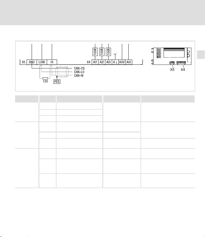
Borniers sur la face inférieure de l’appareil
Borniers sur la face inférieure de l’appareil
Borne Fonction Niveau Données
Entrées
analogiques
Sorties
analogiques
Bus
Système
CAN
X4/AI1
Entrée programmable 1
X4/AI2 Entrée programmable 2
X4/AI3 Entrée programmable 3
X4/AOV Sortie tension
X4/AOI Sortie courant
X4/A⊥ Masse des entrées et
sorties analogiques
X5/GND CAN−GND
X5/LOW CAN−LOW Bus Système LOW
X5/HI CAN−HIGH Bus Système HIGH
Installation électrique
−10 V ... +10 V Résolution : 10 bits + signe
−10 V ... +10 V /
2 mA max.
−20 mA ... +20 mA
− −
Potentiel de
référence
(BAS) (ligne de
données)
(HAUT) (ligne de
données)
Résolution : 10 bits + signe
Précision : ±0.5 %
−
−
−
6
plc003
EDK10200EV3 DE/EN/FR 7.1
95
Page 96

6
Installation électrique
Borniers sur la face inférieure de l’appareil
Remarque importante !
ƒ Pour plus de détails sur l’inversion du niveau des entrées et des sorties
numériques, voir le manuel Drive PLC Developer Studio (DDS), chapitre
DIGITAL_IO".
ƒ Pour le réglage des signaux analogiques d’entrée et de sortie, utiliser le
bloc fonction L_AIN ou L_AOUT. Pour plus de détails, consulter la partie
"Bibliothèque standard 9300 Servo PLC" dans le manuel DDS.
96
EDK10200EV3 DE/EN/FR 7.1
Page 97

Câblage du Bus Système CAN
Stop !
Relier uniquement les bornes ayant la même désignation.
Installation électrique
Câblage du Bus Système CAN
6
Drive PLC
GND LOW
PES
Variateur de vitesse 1
Variateur de vitesse 2
PES Collier de blindage HF via raccord PE
HI
7 LO
120Ω 120Ω
01
HI
PES PES
7 LO
HI
7 LO
HI
7 LO
Caractéristiques du câble
Longueur totale du câble Jusqu’à 300 m De 300 à 1000 m
Type de câble
Résistance de câble £40 W/km £40 W/km
Capacité de câble £130 nF/km £60 nF/km
EDK10200EV3 DE/EN/FR 7.1
LIYCY 2 x 2 x 0.5 mm
(torsadé par paire, avec blindage)
Paire 1 : CAN−LOW (BAS) (LO) et CAN−HIGH (HAUT) (HI)
Paire 2 : 2 x GND
2
CYPIMF 2 x 2 x 0.5 mm
HI
plc014
2
97
Page 98

6
Raccordement des résistances d’extrémité de bus
ƒ Installer la résistance 120 W sur le premier et sur le dernier participant au bus.
ƒ Sur le servovariateur 93XX, la résistance peut être vissée directement en dessous
Caractéristiques
ƒ Base CAN avec protocole de bus selon CANopen (CAL−based Communication Profile
ƒ Longueur du bus
ƒ Fiabilité accrue pour le transfert de données (distance Hamming = 6)
ƒ Niveau du signal selon ISO 11898
ƒ Jusqu’à 63 participants au bus
Installation électrique
Câblage du Bus Système CAN
des bornes X4/HI et X4/LO.
DS301)
– 25 m avec une vitesse de communication max. de 1 Mbit/s max.
– Jusqu’à 1 km avec une vitesse de communication réduite
98
EDK10200EV3 DE/EN/FR 7.1
Page 99

7 Mise en service
Avant la première mise sous tension
Stop !
Ne réaliser le raccordement du module Bus Système entre le PC et le Drive
PLC qu’après vous être assuré que les appareils étaient hors tension.
Mise en service
Avant la première mise sous tension
7
0
l
Drive PLC
Developer Studio
3
PC
Drive PLC
Résistance d’extrémité de bus 120 W
Module Bus Système pour PC
EDK10200EV3 DE/EN/FR 7.1
+18…30VDC/0V
1
X5
GND HI
LOW
120W
2
plc017
99
Page 100

7
Mise en service
Ordre des opérations
Ordre des opérations
1. Vérifier avant la mise sous tension le câblage dans son intégralité afin d’éviter un
court−circuit.
2. Brancher la tension d’alimentation pour le Drive PLC et le PC.
3. Démarrer le logiciel Drive PLC Developer Studio" (DDS).
4. Régler les paramètres de communication. ( Drive PLC Developer Studio −
Premières étapes")
5. Charger le projet souhaité dans le Drive PLC. ( Drive PLC Developer Studio −
Premières étapes")
6. Démarrer le programme. ( Drive PLC Developer Studio − Premières étapes")
Commande du programme
Pour la commande du programme dans le Drive PLC, plusieurs possibilités sont offertes :
Commande par Fonction programme Réglage/paramétrage
Logiciel "Drive PLC Developer
Studio" (DDS)
l Logiciel Global Drive
Control" (GDC)
l Clavier de commande XT
9371BC
*)
Réglage Lenze
Start, Stop, Reset Manuel DDS − Premières étapes"
Démarrage
automatique
Start, Stop, Reset
C2104 = −0− *)Le programme ne démarre pas
C2104 = −1− Le programme démarre
C2108 = −0− *)Fonction exécutée
C2108 = −1− Démarrer le programme.
C2108 = −2− Arrêter le programme.
C2108 = −3− Réinitialiser le programme.
automatiquement après la
mise sous tension.
automatiquement après la
mise sous tension.
100
EDK10200EV3 DE/EN/FR 7.1
 Loading...