

Page 1

Engineering tools
Engineer
Configuring drives_ _ _ _ _ _ _ _ _ _ _ _ _ _ _ _
Software Manual DE
Ä.PE8ä
13473623
L
Page 2
Target group
This documentation is intended for all persons who want to use the »Engineer«
engineering software to parameterise, configure and diagnose field devices and control
systems.
Screenshots/application examples
All screenshots provided in this documentation are application examples. Depending on
the firmware version of the Lenze devices and installed engineering tools (here: Lenze
»Engineer«), the representation may differ from the actual screen display.
Information regarding the validity
The information in this documentation is valid for the following Lenze software:
Software From version
»Engineer« 2.19
Document history
Version Description
2.12 10/2013 TD11 Updated contents for the »Engineer« V2.19 software version
2.11 11/2012 TD11 Updated contents for the »Engineer« V2.17 software version
2.10 05/2012 TD11 Updated contents for the »Engineer« V2.16 software version
2.9 11/2011 TD11 Updated contents for the »Engineer« V2.15 software version
2.8 04/2011 TD11 Updated contents for the »Engineer« V2.14 software version
2.7 11/2010 TD11 Updated contents for the »Engineer« V2.13 software version
2.6 04/2010 TD11 Updated contents for the »Engineer« V2.12 software version
2.5 10/2009 TD11 Updated contents for the software version »Engineer« V2.10 SP3
2.4 08/2009 TD11 Updated chapter: Managing cam data with the »Cam Manager«
2.3 04/2009 TD11 Optimised structures, update of dialog boxes & extension by new functions
of »Engineer« V2.10:
• Data logger
• Compare and copy parameter sets
2.2 11/2008 TD11 Extended by new functions of »Engineer« V2.9:
• L-force Loader Export, optimised menu control, device data update and
establishing an online connection.
• New chapter "Handling catalogues".
2.1 07/2008 TD11 Extended by new functions: User motors, Cam Manager, Cam Editor
2.0 10/2007 TD16 First edition
( 272)
Page 3

Contents
_ _ _ _ _ _ _ _ _ _ _ _ _ _ _ _ _ _ _ _ _ _ _ _ _ _ _ _ _ _ _ _ _ _ _ _ _ _ _ _ _ _ _ _ _ _ _ _ _ _ _ _ _ _ _ _ _ _ _ _ _ _ _ _
1 About this documentation _ _ _ _ _ _ _ _ _ _ _ _ _ _ _ _ _ _ _ _ _ _ _ _ _ _ _ _ _ _ _ _ _ _ _ _ _ _ _ 9
1.1 Conventions used _ _ _ _ _ _ _ _ _ _ _ _ _ _ _ _ _ _ _ _ _ _ _ _ _ _ _ _ _ _ _ _ _ _ _ _ _ _ _ _ _ _ _ _ 10
1.2 Definition of notes used _ _ _ _ _ _ _ _ _ _ _ _ _ _ _ _ _ _ _ _ _ _ _ _ _ _ _ _ _ _ _ _ _ _ _ _ _ _ _ _ _ 11
2Safety instructions _ _ _ _ _ _ _ _ _ _ _ _ _ _ _ _ _ _ _ _ _ _ _ _ _ _ _ _ _ _ _ _ _ _ _ _ _ _ _ _ _ _ _ _ 12
3 User interface _ _ _ _ _ _ _ _ _ _ _ _ _ _ _ _ _ _ _ _ _ _ _ _ _ _ _ _ _ _ _ _ _ _ _ _ _ _ _ _ _ _ _ _ _ _ 13
3.1 Toolbar _ _ _ _ _ _ _ _ _ _ _ _ _ _ _ _ _ _ _ _ _ _ _ _ _ _ _ _ _ _ _ _ _ _ _ _ _ _ _ _ _ _ _ _ _ _ _ _ _ _ 15
3.2 Project view bar: Filtering the project tree _ _ _ _ _ _ _ _ _ _ _ _ _ _ _ _ _ _ _ _ _ _ _ _ _ _ _ _ _ _ _ 17
3.3 Project structure (project tree) _ _ _ _ _ _ _ _ _ _ _ _ _ _ _ _ _ _ _ _ _ _ _ _ _ _ _ _ _ _ _ _ _ _ _ _ _ 18
3.3.1 History of the preselected elements _ _ _ _ _ _ _ _ _ _ _ _ _ _ _ _ _ _ _ _ _ _ _ _ _ _ _ _ _ 19
3.3.2 General editing functions in the project view _ _ _ _ _ _ _ _ _ _ _ _ _ _ _ _ _ _ _ _ _ _ _ _ 19
3.3.3 Shortcuts in the project view _ _ _ _ _ _ _ _ _ _ _ _ _ _ _ _ _ _ _ _ _ _ _ _ _ _ _ _ _ _ _ _ _ 20
3.3.4 Project root _ _ _ _ _ _ _ _ _ _ _ _ _ _ _ _ _ _ _ _ _ _ _ _ _ _ _ _ _ _ _ _ _ _ _ _ _ _ _ _ _ _ _ 21
3.4 Workspace _ _ _ _ _ _ _ _ _ _ _ _ _ _ _ _ _ _ _ _ _ _ _ _ _ _ _ _ _ _ _ _ _ _ _ _ _ _ _ _ _ _ _ _ _ _ _ _ 21
3.4.1 Displaying parameter values _ _ _ _ _ _ _ _ _ _ _ _ _ _ _ _ _ _ _ _ _ _ _ _ _ _ _ _ _ _ _ _ _ 22
3.5 Status information _ _ _ _ _ _ _ _ _ _ _ _ _ _ _ _ _ _ _ _ _ _ _ _ _ _ _ _ _ _ _ _ _ _ _ _ _ _ _ _ _ _ _ 23
3.6 Monitor: Monitoring parameters _ _ _ _ _ _ _ _ _ _ _ _ _ _ _ _ _ _ _ _ _ _ _ _ _ _ _ _ _ _ _ _ _ _ _ _ 24
3.6.1 Show monitor window: Accept parameters/type of presentation _ _ _ _ _ _ _ _ _ _ _ _ _ 24
3.6.2 Adapt monitor window: Show parameters graphically (instruments) _ _ _ _ _ _ _ _ _ _ _ 25
3.6.3 Adapt monitor window: Present parameters graphically (list) _ _ _ _ _ _ _ _ _ _ _ _ _ _ _ 26
3.7 Create _ _ _ _ _ _ _ _ _ _ _ _ _ _ _ _ _ _ _ _ _ _ _ _ _ _ _ _ _ _ _ _ _ _ _ _ _ _ _ _ _ _ _ _ _ _ _ _ _ _ 27
3.8 User menu _ _ _ _ _ _ _ _ _ _ _ _ _ _ _ _ _ _ _ _ _ _ _ _ _ _ _ _ _ _ _ _ _ _ _ _ _ _ _ _ _ _ _ _ _ _ _ _ 27
3.9 Messages _ _ _ _ _ _ _ _ _ _ _ _ _ _ _ _ _ _ _ _ _ _ _ _ _ _ _ _ _ _ _ _ _ _ _ _ _ _ _ _ _ _ _ _ _ _ _ _ _ 27
3.10 Wizards _ _ _ _ _ _ _ _ _ _ _ _ _ _ _ _ _ _ _ _ _ _ _ _ _ _ _ _ _ _ _ _ _ _ _ _ _ _ _ _ _ _ _ _ _ _ _ _ _ _ 28
3.11 Options for the representation/project memory location _ _ _ _ _ _ _ _ _ _ _ _ _ _ _ _ _ _ _ _ _ _ 29
4 Getting started: creating a project _ _ _ _ _ _ _ _ _ _ _ _ _ _ _ _ _ _ _ _ _ _ _ _ _ _ _ _ _ _ _ _ _ _ _ 30
4.1 Creating a new project _ _ _ _ _ _ _ _ _ _ _ _ _ _ _ _ _ _ _ _ _ _ _ _ _ _ _ _ _ _ _ _ _ _ _ _ _ _ _ _ _ 31
4.1.1 Creating a new project (selecting a component from the catalogue) _ _ _ _ _ _ _ _ _ _ _ _ 32
4.1.2 Creating a new project (starting the search for devices connected) _ _ _ _ _ _ _ _ _ _ _ _ 34
4.1.3 Creating an empty project _ _ _ _ _ _ _ _ _ _ _ _ _ _ _ _ _ _ _ _ _ _ _ _ _ _ _ _ _ _ _ _ _ _ _ 37
4.2 Opening the project file _ _ _ _ _ _ _ _ _ _ _ _ _ _ _ _ _ _ _ _ _ _ _ _ _ _ _ _ _ _ _ _ _ _ _ _ _ _ _ _ _ 38
4.3 Updating projects while opening them: Adapting project file from previous version _ _ _ _ _ _ _ _ 39
4.4 Updating catalogues _ _ _ _ _ _ _ _ _ _ _ _ _ _ _ _ _ _ _ _ _ _ _ _ _ _ _ _ _ _ _ _ _ _ _ _ _ _ _ _ _ _ 40
4.5 Project properties _ _ _ _ _ _ _ _ _ _ _ _ _ _ _ _ _ _ _ _ _ _ _ _ _ _ _ _ _ _ _ _ _ _ _ _ _ _ _ _ _ _ _ _ 41
4.6 Save a project _ _ _ _ _ _ _ _ _ _ _ _ _ _ _ _ _ _ _ _ _ _ _ _ _ _ _ _ _ _ _ _ _ _ _ _ _ _ _ _ _ _ _ _ _ _ 42
4.7 Managing projects in a packed archive _ _ _ _ _ _ _ _ _ _ _ _ _ _ _ _ _ _ _ _ _ _ _ _ _ _ _ _ _ _ _ _ _ 43
4.7.1 Saving an archive _ _ _ _ _ _ _ _ _ _ _ _ _ _ _ _ _ _ _ _ _ _ _ _ _ _ _ _ _ _ _ _ _ _ _ _ _ _ _ 43
4.7.2 Open an archive _ _ _ _ _ _ _ _ _ _ _ _ _ _ _ _ _ _ _ _ _ _ _ _ _ _ _ _ _ _ _ _ _ _ _ _ _ _ _ _ 44
5 Mapping the system structure in the »Engineer« project _ _ _ _ _ _ _ _ _ _ _ _ _ _ _ _ _ _ _ _ _ _ _ 45
5.1 Modularising with system modules and axes _ _ _ _ _ _ _ _ _ _ _ _ _ _ _ _ _ _ _ _ _ _ _ _ _ _ _ _ 47
5.1.1 Inserting system modules _ _ _ _ _ _ _ _ _ _ _ _ _ _ _ _ _ _ _ _ _ _ _ _ _ _ _ _ _ _ _ _ _ _ _ 47
5.1.2 Inserting an axis _ _ _ _ _ _ _ _ _ _ _ _ _ _ _ _ _ _ _ _ _ _ _ _ _ _ _ _ _ _ _ _ _ _ _ _ _ _ _ _ 48
5.2 Inserting components _ _ _ _ _ _ _ _ _ _ _ _ _ _ _ _ _ _ _ _ _ _ _ _ _ _ _ _ _ _ _ _ _ _ _ _ _ _ _ _ _ _ 51
5.2.1 Inserting controllers _ _ _ _ _ _ _ _ _ _ _ _ _ _ _ _ _ _ _ _ _ _ _ _ _ _ _ _ _ _ _ _ _ _ _ _ _ _ 53
5.2.2 Inserting application _ _ _ _ _ _ _ _ _ _ _ _ _ _ _ _ _ _ _ _ _ _ _ _ _ _ _ _ _ _ _ _ _ _ _ _ _ _ 55
5.2.3 Inserting device modules _ _ _ _ _ _ _ _ _ _ _ _ _ _ _ _ _ _ _ _ _ _ _ _ _ _ _ _ _ _ _ _ _ _ _ 57
5.2.4 Inserting controllers _ _ _ _ _ _ _ _ _ _ _ _ _ _ _ _ _ _ _ _ _ _ _ _ _ _ _ _ _ _ _ _ _ _ _ _ _ _ 58
5.2.5 Inserting a motor _ _ _ _ _ _ _ _ _ _ _ _ _ _ _ _ _ _ _ _ _ _ _ _ _ _ _ _ _ _ _ _ _ _ _ _ _ _ _ _ 58
5.2.6 Inserting an I/O system _ _ _ _ _ _ _ _ _ _ _ _ _ _ _ _ _ _ _ _ _ _ _ _ _ _ _ _ _ _ _ _ _ _ _ _ 60
5.2.6.1 System 1000 _ _ _ _ _ _ _ _ _ _ _ _ _ _ _ _ _ _ _ _ _ _ _ _ _ _ _ _ _ _ _ _ _ _ _ _ 61
5.2.6.2 Compact I/O system IP20 _ _ _ _ _ _ _ _ _ _ _ _ _ _ _ _ _ _ _ _ _ _ _ _ _ _ _ _ _ 61
5.2.6.3 Modular I/O system IP20 _ _ _ _ _ _ _ _ _ _ _ _ _ _ _ _ _ _ _ _ _ _ _ _ _ _ _ _ _ 61
3 Lenze · Engineer · 2.13 EN - 10/2014
Page 4

Contents
_ _ _ _ _ _ _ _ _ _ _ _ _ _ _ _ _ _ _ _ _ _ _ _ _ _ _ _ _ _ _ _ _ _ _ _ _ _ _ _ _ _ _ _ _ _ _ _ _ _ _ _ _ _ _ _ _ _ _ _ _ _ _ _
5.2.7 Inserting a power supply module _ _ _ _ _ _ _ _ _ _ _ _ _ _ _ _ _ _ _ _ _ _ _ _ _ _ _ _ _ _ _ 63
5.2.8 Inserting the remote maintenance _ _ _ _ _ _ _ _ _ _ _ _ _ _ _ _ _ _ _ _ _ _ _ _ _ _ _ _ _ _ 66
5.3 Inserting a gearbox _ _ _ _ _ _ _ _ _ _ _ _ _ _ _ _ _ _ _ _ _ _ _ _ _ _ _ _ _ _ _ _ _ _ _ _ _ _ _ _ _ _ _ 67
5.4 Inserting a device detected online _ _ _ _ _ _ _ _ _ _ _ _ _ _ _ _ _ _ _ _ _ _ _ _ _ _ _ _ _ _ _ _ _ _ _ 67
5.5 Insert from referential project _ _ _ _ _ _ _ _ _ _ _ _ _ _ _ _ _ _ _ _ _ _ _ _ _ _ _ _ _ _ _ _ _ _ _ _ _ 70
5.6 Replace component _ _ _ _ _ _ _ _ _ _ _ _ _ _ _ _ _ _ _ _ _ _ _ _ _ _ _ _ _ _ _ _ _ _ _ _ _ _ _ _ _ _ _ 71
5.7 Documentation - Add project details _ _ _ _ _ _ _ _ _ _ _ _ _ _ _ _ _ _ _ _ _ _ _ _ _ _ _ _ _ _ _ _ _ _ 71
5.8 Protecting safe parameters - project-related password entry _ _ _ _ _ _ _ _ _ _ _ _ _ _ _ _ _ _ _ _ 74
6 Establishing an online connection _ _ _ _ _ _ _ _ _ _ _ _ _ _ _ _ _ _ _ _ _ _ _ _ _ _ _ _ _ _ _ _ _ _ _ 75
6.1 Build project _ _ _ _ _ _ _ _ _ _ _ _ _ _ _ _ _ _ _ _ _ _ _ _ _ _ _ _ _ _ _ _ _ _ _ _ _ _ _ _ _ _ _ _ _ _ _ 76
6.2 Going online _ _ _ _ _ _ _ _ _ _ _ _ _ _ _ _ _ _ _ _ _ _ _ _ _ _ _ _ _ _ _ _ _ _ _ _ _ _ _ _ _ _ _ _ _ _ _ 77
6.2.1 Setting the communication path _ _ _ _ _ _ _ _ _ _ _ _ _ _ _ _ _ _ _ _ _ _ _ _ _ _ _ _ _ _ _ 79
6.2.1.1 Diagnostic adapter _ _ _ _ _ _ _ _ _ _ _ _ _ _ _ _ _ _ _ _ _ _ _ _ _ _ _ _ _ _ _ _ 80
6.2.1.2 CAN _ _ _ _ _ _ _ _ _ _ _ _ _ _ _ _ _ _ _ _ _ _ _ _ _ _ _ _ _ _ _ _ _ _ _ _ _ _ _ _ _ 81
6.2.1.3 Ethernet / Ethernet IPC _ _ _ _ _ _ _ _ _ _ _ _ _ _ _ _ _ _ _ _ _ _ _ _ _ _ _ _ _ _ 83
6.2.1.4 PROFIBUS _ _ _ _ _ _ _ _ _ _ _ _ _ _ _ _ _ _ _ _ _ _ _ _ _ _ _ _ _ _ _ _ _ _ _ _ _ 84
6.2.1.5 PROFINET _ _ _ _ _ _ _ _ _ _ _ _ _ _ _ _ _ _ _ _ _ _ _ _ _ _ _ _ _ _ _ _ _ _ _ _ _ _ 85
6.2.1.6 Gateway controller -> CAN _ _ _ _ _ _ _ _ _ _ _ _ _ _ _ _ _ _ _ _ _ _ _ _ _ _ _ _ 85
6.2.1.7 Gateway controller -> EtherCAT _ _ _ _ _ _ _ _ _ _ _ _ _ _ _ _ _ _ _ _ _ _ _ _ _ 86
6.2.1.8 Gateway Controller -> EtherCAT ADS (Beckhoff) _ _ _ _ _ _ _ _ _ _ _ _ _ _ _ _ 87
6.2.1.9 Gateway Siemens - STEP 7 Communication Server (available by call in STEP 7) 89
6.2.2 Checking the serial number _ _ _ _ _ _ _ _ _ _ _ _ _ _ _ _ _ _ _ _ _ _ _ _ _ _ _ _ _ _ _ _ _ _ 94
6.2.2.1 Communication path is currently being used by another device _ _ _ _ _ _ _ _ 94
6.2.2.2 Communication path is currently being used by another device _ _ _ _ _ _ _ _ 95
6.2.2.3 Switching off the serial number check _ _ _ _ _ _ _ _ _ _ _ _ _ _ _ _ _ _ _ _ _ _ 96
6.3 Going offline _ _ _ _ _ _ _ _ _ _ _ _ _ _ _ _ _ _ _ _ _ _ _ _ _ _ _ _ _ _ _ _ _ _ _ _ _ _ _ _ _ _ _ _ _ _ _ 96
6.4 System bus configurator _ _ _ _ _ _ _ _ _ _ _ _ _ _ _ _ _ _ _ _ _ _ _ _ _ _ _ _ _ _ _ _ _ _ _ _ _ _ _ _ 96
6.5 PROFINET address configurator _ _ _ _ _ _ _ _ _ _ _ _ _ _ _ _ _ _ _ _ _ _ _ _ _ _ _ _ _ _ _ _ _ _ _ _ _ 97
6.6 EtherNet / IP addresses configurator _ _ _ _ _ _ _ _ _ _ _ _ _ _ _ _ _ _ _ _ _ _ _ _ _ _ _ _ _ _ _ _ _ _ 97
7 Device functions with active online connection _ _ _ _ _ _ _ _ _ _ _ _ _ _ _ _ _ _ _ _ _ _ _ _ _ _ _ _ 98
7.1 Options _ _ _ _ _ _ _ _ _ _ _ _ _ _ _ _ _ _ _ _ _ _ _ _ _ _ _ _ _ _ _ _ _ _ _ _ _ _ _ _ _ _ _ _ _ _ _ _ _ _ 99
7.2 Controlling an inverter: Enable/inhibit, start stop application _ _ _ _ _ _ _ _ _ _ _ _ _ _ _ _ _ _ _ _ 100
7.2.1 Enable controller _ _ _ _ _ _ _ _ _ _ _ _ _ _ _ _ _ _ _ _ _ _ _ _ _ _ _ _ _ _ _ _ _ _ _ _ _ _ _ _ 100
7.2.2 Inhibit controller _ _ _ _ _ _ _ _ _ _ _ _ _ _ _ _ _ _ _ _ _ _ _ _ _ _ _ _ _ _ _ _ _ _ _ _ _ _ _ _ 101
7.2.3 Start application _ _ _ _ _ _ _ _ _ _ _ _ _ _ _ _ _ _ _ _ _ _ _ _ _ _ _ _ _ _ _ _ _ _ _ _ _ _ _ _ 101
7.2.4 Stop application _ _ _ _ _ _ _ _ _ _ _ _ _ _ _ _ _ _ _ _ _ _ _ _ _ _ _ _ _ _ _ _ _ _ _ _ _ _ _ _ 101
7.3 Application and parameter set transfer _ _ _ _ _ _ _ _ _ _ _ _ _ _ _ _ _ _ _ _ _ _ _ _ _ _ _ _ _ _ _ _ 102
7.3.1 Download program to device _ _ _ _ _ _ _ _ _ _ _ _ _ _ _ _ _ _ _ _ _ _ _ _ _ _ _ _ _ _ _ _ _ 103
7.3.2 Download parameter set to device _ _ _ _ _ _ _ _ _ _ _ _ _ _ _ _ _ _ _ _ _ _ _ _ _ _ _ _ _ _ 105
7.3.3 Upload parameter set _ _ _ _ _ _ _ _ _ _ _ _ _ _ _ _ _ _ _ _ _ _ _ _ _ _ _ _ _ _ _ _ _ _ _ _ _ 106
7.3.4 Save parameter set _ _ _ _ _ _ _ _ _ _ _ _ _ _ _ _ _ _ _ _ _ _ _ _ _ _ _ _ _ _ _ _ _ _ _ _ _ _ 107
7.4 Optical tracking - device identification within the machine _ _ _ _ _ _ _ _ _ _ _ _ _ _ _ _ _ _ _ _ _ 107
7.5 Manual control of the motor direction of rotation: Rotating the axes manually _ _ _ _ _ _ _ _ _ _ 109
7.6 Diagnostics _ _ _ _ _ _ _ _ _ _ _ _ _ _ _ _ _ _ _ _ _ _ _ _ _ _ _ _ _ _ _ _ _ _ _ _ _ _ _ _ _ _ _ _ _ _ _ _ 110
7.7 Data logger _ _ _ _ _ _ _ _ _ _ _ _ _ _ _ _ _ _ _ _ _ _ _ _ _ _ _ _ _ _ _ _ _ _ _ _ _ _ _ _ _ _ _ _ _ _ _ _ 111
7.7.1 User interface _ _ _ _ _ _ _ _ _ _ _ _ _ _ _ _ _ _ _ _ _ _ _ _ _ _ _ _ _ _ _ _ _ _ _ _ _ _ _ _ _ 112
7.7.1.1 Data logger toolbar _ _ _ _ _ _ _ _ _ _ _ _ _ _ _ _ _ _ _ _ _ _ _ _ _ _ _ _ _ _ _ _ 112
7.7.1.2 Diagram _ _ _ _ _ _ _ _ _ _ _ _ _ _ _ _ _ _ _ _ _ _ _ _ _ _ _ _ _ _ _ _ _ _ _ _ _ _ 113
7.7.1.3 Vertical settings _ _ _ _ _ _ _ _ _ _ _ _ _ _ _ _ _ _ _ _ _ _ _ _ _ _ _ _ _ _ _ _ _ _ 114
7.7.1.4 Trigger/cursor settings _ _ _ _ _ _ _ _ _ _ _ _ _ _ _ _ _ _ _ _ _ _ _ _ _ _ _ _ _ _ 115
7.7.1.5 Horizontal settings _ _ _ _ _ _ _ _ _ _ _ _ _ _ _ _ _ _ _ _ _ _ _ _ _ _ _ _ _ _ _ _ 115
7.7.1.6 Recording settings _ _ _ _ _ _ _ _ _ _ _ _ _ _ _ _ _ _ _ _ _ _ _ _ _ _ _ _ _ _ _ _ _ 115
4 Lenze · Engineer · 2.13 EN - 10/2014
Page 5

Contents
_ _ _ _ _ _ _ _ _ _ _ _ _ _ _ _ _ _ _ _ _ _ _ _ _ _ _ _ _ _ _ _ _ _ _ _ _ _ _ _ _ _ _ _ _ _ _ _ _ _ _ _ _ _ _ _ _ _ _ _ _ _ _ _
7.7.2 Operation _ _ _ _ _ _ _ _ _ _ _ _ _ _ _ _ _ _ _ _ _ _ _ _ _ _ _ _ _ _ _ _ _ _ _ _ _ _ _ _ _ _ _ _ 116
7.7.2.1 Selecting the variables to be recorded _ _ _ _ _ _ _ _ _ _ _ _ _ _ _ _ _ _ _ _ _ _ 116
7.7.2.2 Defining the recording time/sampling rate _ _ _ _ _ _ _ _ _ _ _ _ _ _ _ _ _ _ _ 117
7.7.2.3 Defining the trigger condition _ _ _ _ _ _ _ _ _ _ _ _ _ _ _ _ _ _ _ _ _ _ _ _ _ _ 118
7.7.2.4 Using the time axis _ _ _ _ _ _ _ _ _ _ _ _ _ _ _ _ _ _ _ _ _ _ _ _ _ _ _ _ _ _ _ _ 119
7.7.2.5 Starting/stopping recording _ _ _ _ _ _ _ _ _ _ _ _ _ _ _ _ _ _ _ _ _ _ _ _ _ _ _ 119
7.7.2.6 Adjusting the representation _ _ _ _ _ _ _ _ _ _ _ _ _ _ _ _ _ _ _ _ _ _ _ _ _ _ _ 120
7.7.2.7 Reading individual measured values _ _ _ _ _ _ _ _ _ _ _ _ _ _ _ _ _ _ _ _ _ _ _ 121
7.7.2.8 Comparing peak values _ _ _ _ _ _ _ _ _ _ _ _ _ _ _ _ _ _ _ _ _ _ _ _ _ _ _ _ _ _ 121
7.7.3 Data records _ _ _ _ _ _ _ _ _ _ _ _ _ _ _ _ _ _ _ _ _ _ _ _ _ _ _ _ _ _ _ _ _ _ _ _ _ _ _ _ _ _ 122
7.7.3.1 Commenting a data record _ _ _ _ _ _ _ _ _ _ _ _ _ _ _ _ _ _ _ _ _ _ _ _ _ _ _ _ 122
7.7.3.2 Saving/exporting a data record _ _ _ _ _ _ _ _ _ _ _ _ _ _ _ _ _ _ _ _ _ _ _ _ _ _ 123
7.7.3.3 Loading/importing data records _ _ _ _ _ _ _ _ _ _ _ _ _ _ _ _ _ _ _ _ _ _ _ _ _ 124
7.7.3.4 Closing the data record _ _ _ _ _ _ _ _ _ _ _ _ _ _ _ _ _ _ _ _ _ _ _ _ _ _ _ _ _ _ 125
7.7.3.5 Deleting a data record in the project _ _ _ _ _ _ _ _ _ _ _ _ _ _ _ _ _ _ _ _ _ _ _ 125
7.7.3.6 Overlay function _ _ _ _ _ _ _ _ _ _ _ _ _ _ _ _ _ _ _ _ _ _ _ _ _ _ _ _ _ _ _ _ _ _ 126
7.7.3.7 Copying a data record to the clipboard _ _ _ _ _ _ _ _ _ _ _ _ _ _ _ _ _ _ _ _ _ _ 126
7.8 Oscilloscope _ _ _ _ _ _ _ _ _ _ _ _ _ _ _ _ _ _ _ _ _ _ _ _ _ _ _ _ _ _ _ _ _ _ _ _ _ _ _ _ _ _ _ _ _ _ _ 127
8 Defining the system functionality _ _ _ _ _ _ _ _ _ _ _ _ _ _ _ _ _ _ _ _ _ _ _ _ _ _ _ _ _ _ _ _ _ _ _ 128
8.1 Representation in the project view _ _ _ _ _ _ _ _ _ _ _ _ _ _ _ _ _ _ _ _ _ _ _ _ _ _ _ _ _ _ _ _ _ _ _ 128
8.2 Terminology used _ _ _ _ _ _ _ _ _ _ _ _ _ _ _ _ _ _ _ _ _ _ _ _ _ _ _ _ _ _ _ _ _ _ _ _ _ _ _ _ _ _ _ _ 129
8.3 General notes with regard to the procedure _ _ _ _ _ _ _ _ _ _ _ _ _ _ _ _ _ _ _ _ _ _ _ _ _ _ _ _ _ _ 131
8.4 Parameterising & configuring the devices _ _ _ _ _ _ _ _ _ _ _ _ _ _ _ _ _ _ _ _ _ _ _ _ _ _ _ _ _ _ _ 132
8.5 Assigning an application to the device _ _ _ _ _ _ _ _ _ _ _ _ _ _ _ _ _ _ _ _ _ _ _ _ _ _ _ _ _ _ _ _ _ 133
8.6 Parameter setting in the »Engineer« _ _ _ _ _ _ _ _ _ _ _ _ _ _ _ _ _ _ _ _ _ _ _ _ _ _ _ _ _ _ _ _ _ _ 134
8.6.1 Terminology used _ _ _ _ _ _ _ _ _ _ _ _ _ _ _ _ _ _ _ _ _ _ _ _ _ _ _ _ _ _ _ _ _ _ _ _ _ _ _ 134
8.6.2 Working in the parameter list _ _ _ _ _ _ _ _ _ _ _ _ _ _ _ _ _ _ _ _ _ _ _ _ _ _ _ _ _ _ _ _ _ 135
8.6.3 Altering a parameter offline _ _ _ _ _ _ _ _ _ _ _ _ _ _ _ _ _ _ _ _ _ _ _ _ _ _ _ _ _ _ _ _ _ _ 136
8.6.4 Altering parameters online _ _ _ _ _ _ _ _ _ _ _ _ _ _ _ _ _ _ _ _ _ _ _ _ _ _ _ _ _ _ _ _ _ _ 137
8.6.4.1 Resetting parameters to the default setting _ _ _ _ _ _ _ _ _ _ _ _ _ _ _ _ _ _ _ 138
8.6.4.2 Accepting the parameter settings of the device _ _ _ _ _ _ _ _ _ _ _ _ _ _ _ _ _ 138
8.6.5 Accepting parameter settings in the device _ _ _ _ _ _ _ _ _ _ _ _ _ _ _ _ _ _ _ _ _ _ _ _ _ 139
8.6.6 Comparing parameter sets _ _ _ _ _ _ _ _ _ _ _ _ _ _ _ _ _ _ _ _ _ _ _ _ _ _ _ _ _ _ _ _ _ _ 139
8.7 Copying parameter sets _ _ _ _ _ _ _ _ _ _ _ _ _ _ _ _ _ _ _ _ _ _ _ _ _ _ _ _ _ _ _ _ _ _ _ _ _ _ _ _ _ 143
8.8 Configuring the terminal assignment _ _ _ _ _ _ _ _ _ _ _ _ _ _ _ _ _ _ _ _ _ _ _ _ _ _ _ _ _ _ _ _ _ 144
8.8.1 Changing the terminal assignment _ _ _ _ _ _ _ _ _ _ _ _ _ _ _ _ _ _ _ _ _ _ _ _ _ _ _ _ _ _ 144
8.8.2 Setting the gain & offset of the analog terminals _ _ _ _ _ _ _ _ _ _ _ _ _ _ _ _ _ _ _ _ _ _ 144
8.8.3 Setting the active level of the digital terminals _ _ _ _ _ _ _ _ _ _ _ _ _ _ _ _ _ _ _ _ _ _ _ 145
8.8.4 Displaying the actual status of the terminals _ _ _ _ _ _ _ _ _ _ _ _ _ _ _ _ _ _ _ _ _ _ _ _ 145
8.9 Parameterising the application _ _ _ _ _ _ _ _ _ _ _ _ _ _ _ _ _ _ _ _ _ _ _ _ _ _ _ _ _ _ _ _ _ _ _ _ _ 146
8.9.1 Working in the "Application parameters" tab _ _ _ _ _ _ _ _ _ _ _ _ _ _ _ _ _ _ _ _ _ _ _ _ 146
8.9.1.1 Going directly to a parameter dialog _ _ _ _ _ _ _ _ _ _ _ _ _ _ _ _ _ _ _ _ _ _ _ 148
8.10 Function block editor (FB Editor) _ _ _ _ _ _ _ _ _ _ _ _ _ _ _ _ _ _ _ _ _ _ _ _ _ _ _ _ _ _ _ _ _ _ _ _ 149
8.10.1 Connecting FBs _ _ _ _ _ _ _ _ _ _ _ _ _ _ _ _ _ _ _ _ _ _ _ _ _ _ _ _ _ _ _ _ _ _ _ _ _ _ _ _ _ 151
8.10.2 Navigating within the FB Editor _ _ _ _ _ _ _ _ _ _ _ _ _ _ _ _ _ _ _ _ _ _ _ _ _ _ _ _ _ _ _ _ 153
8.10.3 Printing the function block interconnection _ _ _ _ _ _ _ _ _ _ _ _ _ _ _ _ _ _ _ _ _ _ _ _ _ 154
8.11 Port editor (ports) _ _ _ _ _ _ _ _ _ _ _ _ _ _ _ _ _ _ _ _ _ _ _ _ _ _ _ _ _ _ _ _ _ _ _ _ _ _ _ _ _ _ _ _ 155
8.11.1 Overview: Variable types for ports _ _ _ _ _ _ _ _ _ _ _ _ _ _ _ _ _ _ _ _ _ _ _ _ _ _ _ _ _ _ 156
8.11.1.1 "Simple" variable type _ _ _ _ _ _ _ _ _ _ _ _ _ _ _ _ _ _ _ _ _ _ _ _ _ _ _ _ _ _ _ 157
8.11.1.2 "Record" variable type _ _ _ _ _ _ _ _ _ _ _ _ _ _ _ _ _ _ _ _ _ _ _ _ _ _ _ _ _ _ _ 159
8.11.1.3 "Array" variable type _ _ _ _ _ _ _ _ _ _ _ _ _ _ _ _ _ _ _ _ _ _ _ _ _ _ _ _ _ _ _ 159
8.11.1.4 Record or Simple? _ _ _ _ _ _ _ _ _ _ _ _ _ _ _ _ _ _ _ _ _ _ _ _ _ _ _ _ _ _ _ _ _ 160
Lenze · Engineer · 2.13 EN - 10/2014 5
Page 6

Contents
_ _ _ _ _ _ _ _ _ _ _ _ _ _ _ _ _ _ _ _ _ _ _ _ _ _ _ _ _ _ _ _ _ _ _ _ _ _ _ _ _ _ _ _ _ _ _ _ _ _ _ _ _ _ _ _ _ _ _ _ _ _ _ _
8.11.2 Adding a port _ _ _ _ _ _ _ _ _ _ _ _ _ _ _ _ _ _ _ _ _ _ _ _ _ _ _ _ _ _ _ _ _ _ _ _ _ _ _ _ _ _ 162
8.11.2.1 Defining port with "Simple" variable type _ _ _ _ _ _ _ _ _ _ _ _ _ _ _ _ _ _ _ _ 163
8.11.2.2 Defining a port with "Record" variable type _ _ _ _ _ _ _ _ _ _ _ _ _ _ _ _ _ _ _ 163
8.11.2.3 Define a port with "Array" variable type _ _ _ _ _ _ _ _ _ _ _ _ _ _ _ _ _ _ _ _ _ 165
8.11.2.4 Defining element variables for "Record" variable type _ _ _ _ _ _ _ _ _ _ _ _ _ 166
8.11.2.5 Defining the interface and process data object _ _ _ _ _ _ _ _ _ _ _ _ _ _ _ _ _ 168
8.11.3 Renaming a port _ _ _ _ _ _ _ _ _ _ _ _ _ _ _ _ _ _ _ _ _ _ _ _ _ _ _ _ _ _ _ _ _ _ _ _ _ _ _ _ 169
8.11.4 Deleting a port _ _ _ _ _ _ _ _ _ _ _ _ _ _ _ _ _ _ _ _ _ _ _ _ _ _ _ _ _ _ _ _ _ _ _ _ _ _ _ _ _ 169
8.12 User menu _ _ _ _ _ _ _ _ _ _ _ _ _ _ _ _ _ _ _ _ _ _ _ _ _ _ _ _ _ _ _ _ _ _ _ _ _ _ _ _ _ _ _ _ _ _ _ _ 170
8.12.1 Configuring the user menu _ _ _ _ _ _ _ _ _ _ _ _ _ _ _ _ _ _ _ _ _ _ _ _ _ _ _ _ _ _ _ _ _ _ 171
8.12.2 Transferring the parameter selection to other controllers (in-project) _ _ _ _ _ _ _ _ _ _ _ 172
8.13 Inserting & configuring a machine application _ _ _ _ _ _ _ _ _ _ _ _ _ _ _ _ _ _ _ _ _ _ _ _ _ _ _ _ 173
8.13.1 Inserting a machine application with a port interconnection _ _ _ _ _ _ _ _ _ _ _ _ _ _ _ _ 174
8.13.2 Port interconnection _ _ _ _ _ _ _ _ _ _ _ _ _ _ _ _ _ _ _ _ _ _ _ _ _ _ _ _ _ _ _ _ _ _ _ _ _ _ 175
8.13.2.1 Carrying out assignments _ _ _ _ _ _ _ _ _ _ _ _ _ _ _ _ _ _ _ _ _ _ _ _ _ _ _ _ _ 175
8.13.2.2 Cancelling assignments _ _ _ _ _ _ _ _ _ _ _ _ _ _ _ _ _ _ _ _ _ _ _ _ _ _ _ _ _ _ 176
8.13.3 Connecting ports within the machine application _ _ _ _ _ _ _ _ _ _ _ _ _ _ _ _ _ _ _ _ _ _ 177
8.13.4 Adding ports as an external interface _ _ _ _ _ _ _ _ _ _ _ _ _ _ _ _ _ _ _ _ _ _ _ _ _ _ _ _ _ 179
8.13.5 Defining the type of connection _ _ _ _ _ _ _ _ _ _ _ _ _ _ _ _ _ _ _ _ _ _ _ _ _ _ _ _ _ _ _ 179
8.13.5.1 Automatic connection _ _ _ _ _ _ _ _ _ _ _ _ _ _ _ _ _ _ _ _ _ _ _ _ _ _ _ _ _ _ _ 180
8.13.5.2 Manual connection _ _ _ _ _ _ _ _ _ _ _ _ _ _ _ _ _ _ _ _ _ _ _ _ _ _ _ _ _ _ _ _ 180
8.13.5.3 Specifying the procedure for assigning the COB-IDs _ _ _ _ _ _ _ _ _ _ _ _ _ _ 181
8.13.5.4 Mixed connection _ _ _ _ _ _ _ _ _ _ _ _ _ _ _ _ _ _ _ _ _ _ _ _ _ _ _ _ _ _ _ _ _ 182
8.14 Creating an interconnection via the electrical shaft _ _ _ _ _ _ _ _ _ _ _ _ _ _ _ _ _ _ _ _ _ _ _ _ _ _ 182
8.14.1 Fixed synchronisation of the tools with regard to each other _ _ _ _ _ _ _ _ _ _ _ _ _ _ _ _ 183
8.14.2 Synchronisation of the tools with a material _ _ _ _ _ _ _ _ _ _ _ _ _ _ _ _ _ _ _ _ _ _ _ _ _ 184
8.14.3 Virtual master/real master _ _ _ _ _ _ _ _ _ _ _ _ _ _ _ _ _ _ _ _ _ _ _ _ _ _ _ _ _ _ _ _ _ _ 185
8.14.4 Establishing an interconnection via an electrical shaft _ _ _ _ _ _ _ _ _ _ _ _ _ _ _ _ _ _ _ 186
8.14.4.1 Adding placeholders to the interconnection _ _ _ _ _ _ _ _ _ _ _ _ _ _ _ _ _ _ _ 190
8.14.4.2 Assigning an axis to a placeholder _ _ _ _ _ _ _ _ _ _ _ _ _ _ _ _ _ _ _ _ _ _ _ _ 191
8.14.4.3 Cancelling existing assignments _ _ _ _ _ _ _ _ _ _ _ _ _ _ _ _ _ _ _ _ _ _ _ _ _ 193
8.14.4.4 Reusing the "Electrical shaft" object _ _ _ _ _ _ _ _ _ _ _ _ _ _ _ _ _ _ _ _ _ _ _ 193
8.14.5 Measuring systems _ _ _ _ _ _ _ _ _ _ _ _ _ _ _ _ _ _ _ _ _ _ _ _ _ _ _ _ _ _ _ _ _ _ _ _ _ _ 194
8.14.5.1 Unlimited/limited/modulo traversing range _ _ _ _ _ _ _ _ _ _ _ _ _ _ _ _ _ _ 196
8.14.5.2 Creating/editing/deleting measuring systems _ _ _ _ _ _ _ _ _ _ _ _ _ _ _ _ _ 199
9 Inserting & configuring a network _ _ _ _ _ _ _ _ _ _ _ _ _ _ _ _ _ _ _ _ _ _ _ _ _ _ _ _ _ _ _ _ _ _ _ 202
9.1 Separation of the application and the network _ _ _ _ _ _ _ _ _ _ _ _ _ _ _ _ _ _ _ _ _ _ _ _ _ _ _ _ 203
9.1.1 Application level _ _ _ _ _ _ _ _ _ _ _ _ _ _ _ _ _ _ _ _ _ _ _ _ _ _ _ _ _ _ _ _ _ _ _ _ _ _ _ _ 203
9.1.2 Network level _ _ _ _ _ _ _ _ _ _ _ _ _ _ _ _ _ _ _ _ _ _ _ _ _ _ _ _ _ _ _ _ _ _ _ _ _ _ _ _ _ _ 205
9.2 Inserting a network _ _ _ _ _ _ _ _ _ _ _ _ _ _ _ _ _ _ _ _ _ _ _ _ _ _ _ _ _ _ _ _ _ _ _ _ _ _ _ _ _ _ _ 207
9.3 ETHERNET Powerlink network _ _ _ _ _ _ _ _ _ _ _ _ _ _ _ _ _ _ _ _ _ _ _ _ _ _ _ _ _ _ _ _ _ _ _ _ _ 210
9.3.1 Nodes _ _ _ _ _ _ _ _ _ _ _ _ _ _ _ _ _ _ _ _ _ _ _ _ _ _ _ _ _ _ _ _ _ _ _ _ _ _ _ _ _ _ _ _ _ _ 210
9.3.1.1 Inserting nodes _ _ _ _ _ _ _ _ _ _ _ _ _ _ _ _ _ _ _ _ _ _ _ _ _ _ _ _ _ _ _ _ _ _ 212
9.3.1.2 Node settings _ _ _ _ _ _ _ _ _ _ _ _ _ _ _ _ _ _ _ _ _ _ _ _ _ _ _ _ _ _ _ _ _ _ _ 214
9.3.1.3 Removing nodes _ _ _ _ _ _ _ _ _ _ _ _ _ _ _ _ _ _ _ _ _ _ _ _ _ _ _ _ _ _ _ _ _ _ 214
9.3.2 Settings _ _ _ _ _ _ _ _ _ _ _ _ _ _ _ _ _ _ _ _ _ _ _ _ _ _ _ _ _ _ _ _ _ _ _ _ _ _ _ _ _ _ _ _ _ 215
9.3.3 Product features _ _ _ _ _ _ _ _ _ _ _ _ _ _ _ _ _ _ _ _ _ _ _ _ _ _ _ _ _ _ _ _ _ _ _ _ _ _ _ _ 215
9.3.4 Diagnostics _ _ _ _ _ _ _ _ _ _ _ _ _ _ _ _ _ _ _ _ _ _ _ _ _ _ _ _ _ _ _ _ _ _ _ _ _ _ _ _ _ _ _ 215
9.4 CAN network _ _ _ _ _ _ _ _ _ _ _ _ _ _ _ _ _ _ _ _ _ _ _ _ _ _ _ _ _ _ _ _ _ _ _ _ _ _ _ _ _ _ _ _ _ _ _ 216
9.4.1 Nodes _ _ _ _ _ _ _ _ _ _ _ _ _ _ _ _ _ _ _ _ _ _ _ _ _ _ _ _ _ _ _ _ _ _ _ _ _ _ _ _ _ _ _ _ _ _ 216
9.4.1.1 Inserting nodes _ _ _ _ _ _ _ _ _ _ _ _ _ _ _ _ _ _ _ _ _ _ _ _ _ _ _ _ _ _ _ _ _ _ 218
9.4.1.2 Node settings _ _ _ _ _ _ _ _ _ _ _ _ _ _ _ _ _ _ _ _ _ _ _ _ _ _ _ _ _ _ _ _ _ _ _ 219
9.4.1.3 Removing nodes _ _ _ _ _ _ _ _ _ _ _ _ _ _ _ _ _ _ _ _ _ _ _ _ _ _ _ _ _ _ _ _ _ _ 220
9.4.2 Settings _ _ _ _ _ _ _ _ _ _ _ _ _ _ _ _ _ _ _ _ _ _ _ _ _ _ _ _ _ _ _ _ _ _ _ _ _ _ _ _ _ _ _ _ _ 221
6 Lenze · Engineer · 2.13 EN - 10/2014
Page 7

Contents
_ _ _ _ _ _ _ _ _ _ _ _ _ _ _ _ _ _ _ _ _ _ _ _ _ _ _ _ _ _ _ _ _ _ _ _ _ _ _ _ _ _ _ _ _ _ _ _ _ _ _ _ _ _ _ _ _ _ _ _ _ _ _ _
9.4.3 Synchronisation _ _ _ _ _ _ _ _ _ _ _ _ _ _ _ _ _ _ _ _ _ _ _ _ _ _ _ _ _ _ _ _ _ _ _ _ _ _ _ _ 223
9.4.4 CAN objects _ _ _ _ _ _ _ _ _ _ _ _ _ _ _ _ _ _ _ _ _ _ _ _ _ _ _ _ _ _ _ _ _ _ _ _ _ _ _ _ _ _ _ 225
9.4.5 Product features _ _ _ _ _ _ _ _ _ _ _ _ _ _ _ _ _ _ _ _ _ _ _ _ _ _ _ _ _ _ _ _ _ _ _ _ _ _ _ _ 225
9.5 Process data objects _ _ _ _ _ _ _ _ _ _ _ _ _ _ _ _ _ _ _ _ _ _ _ _ _ _ _ _ _ _ _ _ _ _ _ _ _ _ _ _ _ _ _ 226
9.5.1 Packing ports into process data objects _ _ _ _ _ _ _ _ _ _ _ _ _ _ _ _ _ _ _ _ _ _ _ _ _ _ _ 227
10 Application examples _ _ _ _ _ _ _ _ _ _ _ _ _ _ _ _ _ _ _ _ _ _ _ _ _ _ _ _ _ _ _ _ _ _ _ _ _ _ _ _ _ _ 228
10.1 Interconnection of an I/O terminal with a 9400 HighLine _ _ _ _ _ _ _ _ _ _ _ _ _ _ _ _ _ _ _ _ _ _ 228
10.2 PROFIBUS nodes _ _ _ _ _ _ _ _ _ _ _ _ _ _ _ _ _ _ _ _ _ _ _ _ _ _ _ _ _ _ _ _ _ _ _ _ _ _ _ _ _ _ _ _ _ 230
11 Catalogue management in the »Engineer« _ _ _ _ _ _ _ _ _ _ _ _ _ _ _ _ _ _ _ _ _ _ _ _ _ _ _ _ _ _ 232
11.1 General information about catalogues _ _ _ _ _ _ _ _ _ _ _ _ _ _ _ _ _ _ _ _ _ _ _ _ _ _ _ _ _ _ _ _ _ 232
11.2 Catalogue packages _ _ _ _ _ _ _ _ _ _ _ _ _ _ _ _ _ _ _ _ _ _ _ _ _ _ _ _ _ _ _ _ _ _ _ _ _ _ _ _ _ _ _ 233
11.3 Installation of catalogues _ _ _ _ _ _ _ _ _ _ _ _ _ _ _ _ _ _ _ _ _ _ _ _ _ _ _ _ _ _ _ _ _ _ _ _ _ _ _ _ 233
11.4 Use of catalogues in projects _ _ _ _ _ _ _ _ _ _ _ _ _ _ _ _ _ _ _ _ _ _ _ _ _ _ _ _ _ _ _ _ _ _ _ _ _ _ 233
11.4.1 Relationship between project and catalogues _ _ _ _ _ _ _ _ _ _ _ _ _ _ _ _ _ _ _ _ _ _ _ _ 233
11.4.2 Characteristics of the elements _ _ _ _ _ _ _ _ _ _ _ _ _ _ _ _ _ _ _ _ _ _ _ _ _ _ _ _ _ _ _ _ 234
11.5 Management of catalogue versions _ _ _ _ _ _ _ _ _ _ _ _ _ _ _ _ _ _ _ _ _ _ _ _ _ _ _ _ _ _ _ _ _ _ 236
11.5.1 Objects of versioning _ _ _ _ _ _ _ _ _ _ _ _ _ _ _ _ _ _ _ _ _ _ _ _ _ _ _ _ _ _ _ _ _ _ _ _ _ 236
11.5.2 Procedure for the provision of new versions _ _ _ _ _ _ _ _ _ _ _ _ _ _ _ _ _ _ _ _ _ _ _ _ _ 236
11.6 Particularities of the user motor catalogue _ _ _ _ _ _ _ _ _ _ _ _ _ _ _ _ _ _ _ _ _ _ _ _ _ _ _ _ _ _ 237
12 Error messages _ _ _ _ _ _ _ _ _ _ _ _ _ _ _ _ _ _ _ _ _ _ _ _ _ _ _ _ _ _ _ _ _ _ _ _ _ _ _ _ _ _ _ _ _ _ 238
12.1 Application Connection Generator _ _ _ _ _ _ _ _ _ _ _ _ _ _ _ _ _ _ _ _ _ _ _ _ _ _ _ _ _ _ _ _ _ _ _ 238
12.2 PortLogic generator _ _ _ _ _ _ _ _ _ _ _ _ _ _ _ _ _ _ _ _ _ _ _ _ _ _ _ _ _ _ _ _ _ _ _ _ _ _ _ _ _ _ _ 241
12.3 CAN generator _ _ _ _ _ _ _ _ _ _ _ _ _ _ _ _ _ _ _ _ _ _ _ _ _ _ _ _ _ _ _ _ _ _ _ _ _ _ _ _ _ _ _ _ _ _ 243
12.3.1 Addresses _ _ _ _ _ _ _ _ _ _ _ _ _ _ _ _ _ _ _ _ _ _ _ _ _ _ _ _ _ _ _ _ _ _ _ _ _ _ _ _ _ _ _ _ 243
12.3.2 Baud rate and MMT master _ _ _ _ _ _ _ _ _ _ _ _ _ _ _ _ _ _ _ _ _ _ _ _ _ _ _ _ _ _ _ _ _ _ 244
12.3.3 Synchronisation _ _ _ _ _ _ _ _ _ _ _ _ _ _ _ _ _ _ _ _ _ _ _ _ _ _ _ _ _ _ _ _ _ _ _ _ _ _ _ _ 245
12.3.4 COB-ID _ _ _ _ _ _ _ _ _ _ _ _ _ _ _ _ _ _ _ _ _ _ _ _ _ _ _ _ _ _ _ _ _ _ _ _ _ _ _ _ _ _ _ _ _ 246
12.3.5 Ports and PDO _ _ _ _ _ _ _ _ _ _ _ _ _ _ _ _ _ _ _ _ _ _ _ _ _ _ _ _ _ _ _ _ _ _ _ _ _ _ _ _ _ 248
12.4 Communication entity generator _ _ _ _ _ _ _ _ _ _ _ _ _ _ _ _ _ _ _ _ _ _ _ _ _ _ _ _ _ _ _ _ _ _ _ _ 249
12.4.1 Standard (9300 servo + 9300 ServoPLC) _ _ _ _ _ _ _ _ _ _ _ _ _ _ _ _ _ _ _ _ _ _ _ _ _ _ _ 249
12.4.2 Compact (8200) _ _ _ _ _ _ _ _ _ _ _ _ _ _ _ _ _ _ _ _ _ _ _ _ _ _ _ _ _ _ _ _ _ _ _ _ _ _ _ _ 252
12.4.3 9400 On board _ _ _ _ _ _ _ _ _ _ _ _ _ _ _ _ _ _ _ _ _ _ _ _ _ _ _ _ _ _ _ _ _ _ _ _ _ _ _ _ _ 253
12.4.4 I/O system IP20 (modular and compact) _ _ _ _ _ _ _ _ _ _ _ _ _ _ _ _ _ _ _ _ _ _ _ _ _ _ _ 255
12.4.5 9400 PROFIBUS module _ _ _ _ _ _ _ _ _ _ _ _ _ _ _ _ _ _ _ _ _ _ _ _ _ _ _ _ _ _ _ _ _ _ _ _ 255
13 Menu reference - Overview of the menu commands _ _ _ _ _ _ _ _ _ _ _ _ _ _ _ _ _ _ _ _ _ _ _ _ _ 257
13.1 "File" menu _ _ _ _ _ _ _ _ _ _ _ _ _ _ _ _ _ _ _ _ _ _ _ _ _ _ _ _ _ _ _ _ _ _ _ _ _ _ _ _ _ _ _ _ _ _ _ _ 258
13.2 "Edit" menu _ _ _ _ _ _ _ _ _ _ _ _ _ _ _ _ _ _ _ _ _ _ _ _ _ _ _ _ _ _ _ _ _ _ _ _ _ _ _ _ _ _ _ _ _ _ _ 259
13.3 "Insert" menu _ _ _ _ _ _ _ _ _ _ _ _ _ _ _ _ _ _ _ _ _ _ _ _ _ _ _ _ _ _ _ _ _ _ _ _ _ _ _ _ _ _ _ _ _ _ 260
13.4 "View" menu _ _ _ _ _ _ _ _ _ _ _ _ _ _ _ _ _ _ _ _ _ _ _ _ _ _ _ _ _ _ _ _ _ _ _ _ _ _ _ _ _ _ _ _ _ _ _ 260
13.5 "Online" menu _ _ _ _ _ _ _ _ _ _ _ _ _ _ _ _ _ _ _ _ _ _ _ _ _ _ _ _ _ _ _ _ _ _ _ _ _ _ _ _ _ _ _ _ _ _ 260
13.6 "Application data" menu _ _ _ _ _ _ _ _ _ _ _ _ _ _ _ _ _ _ _ _ _ _ _ _ _ _ _ _ _ _ _ _ _ _ _ _ _ _ _ _ 262
13.7 "Tools" menu _ _ _ _ _ _ _ _ _ _ _ _ _ _ _ _ _ _ _ _ _ _ _ _ _ _ _ _ _ _ _ _ _ _ _ _ _ _ _ _ _ _ _ _ _ _ _ 263
13.8 "?" menu _ _ _ _ _ _ _ _ _ _ _ _ _ _ _ _ _ _ _ _ _ _ _ _ _ _ _ _ _ _ _ _ _ _ _ _ _ _ _ _ _ _ _ _ _ _ _ _ _ 263
13.9 "Project tree/project element" context menu _ _ _ _ _ _ _ _ _ _ _ _ _ _ _ _ _ _ _ _ _ _ _ _ _ _ _ _ _ 265
Lenze · Engineer · 2.13 EN - 10/2014 7
Page 8

Contents
_ _ _ _ _ _ _ _ _ _ _ _ _ _ _ _ _ _ _ _ _ _ _ _ _ _ _ _ _ _ _ _ _ _ _ _ _ _ _ _ _ _ _ _ _ _ _ _ _ _ _ _ _ _ _ _ _ _ _ _ _ _ _ _
14 Appendix _ _ _ _ _ _ _ _ _ _ _ _ _ _ _ _ _ _ _ _ _ _ _ _ _ _ _ _ _ _ _ _ _ _ _ _ _ _ _ _ _ _ _ _ _ _ _ _ _ 266
14.1 Export data _ _ _ _ _ _ _ _ _ _ _ _ _ _ _ _ _ _ _ _ _ _ _ _ _ _ _ _ _ _ _ _ _ _ _ _ _ _ _ _ _ _ _ _ _ _ _ _ 266
14.1.1 Export applications to a Lenze package (LPK file) _ _ _ _ _ _ _ _ _ _ _ _ _ _ _ _ _ _ _ _ _ _ 267
14.1.2 Export device description to a Lenze package (LPK file) _ _ _ _ _ _ _ _ _ _ _ _ _ _ _ _ _ _ _ 268
14.1.3 Export parameters to a »L-force Loader« (LFL) file _ _ _ _ _ _ _ _ _ _ _ _ _ _ _ _ _ _ _ _ _ _ 269
14.1.4 Export parameter values of the devices _ _ _ _ _ _ _ _ _ _ _ _ _ _ _ _ _ _ _ _ _ _ _ _ _ _ _ 269
14.1.4.1 Export all device parameters /Export individual parameters across devices _ _ 270
14.1.4.2 Export the parameter values of a single device _ _ _ _ _ _ _ _ _ _ _ _ _ _ _ _ _ 271
14.2 Managing cam data with the »Cam Manager« _ _ _ _ _ _ _ _ _ _ _ _ _ _ _ _ _ _ _ _ _ _ _ _ _ _ _ _ 272
14.2.1 Adding/editing/deleting products _ _ _ _ _ _ _ _ _ _ _ _ _ _ _ _ _ _ _ _ _ _ _ _ _ _ _ _ _ _ 273
14.2.2 Adding/editing/deleting tracks _ _ _ _ _ _ _ _ _ _ _ _ _ _ _ _ _ _ _ _ _ _ _ _ _ _ _ _ _ _ _ _ 275
14.2.3 Import data _ _ _ _ _ _ _ _ _ _ _ _ _ _ _ _ _ _ _ _ _ _ _ _ _ _ _ _ _ _ _ _ _ _ _ _ _ _ _ _ _ _ _ 276
14.2.4 DSD export _ _ _ _ _ _ _ _ _ _ _ _ _ _ _ _ _ _ _ _ _ _ _ _ _ _ _ _ _ _ _ _ _ _ _ _ _ _ _ _ _ _ _ 277
14.2.5 Displaying project information _ _ _ _ _ _ _ _ _ _ _ _ _ _ _ _ _ _ _ _ _ _ _ _ _ _ _ _ _ _ _ _ 278
14.3 Creating cam data with the »Cam Editor« _ _ _ _ _ _ _ _ _ _ _ _ _ _ _ _ _ _ _ _ _ _ _ _ _ _ _ _ _ _ _ 279
14.3.1 User interface _ _ _ _ _ _ _ _ _ _ _ _ _ _ _ _ _ _ _ _ _ _ _ _ _ _ _ _ _ _ _ _ _ _ _ _ _ _ _ _ _ 280
14.3.2 Creating curves _ _ _ _ _ _ _ _ _ _ _ _ _ _ _ _ _ _ _ _ _ _ _ _ _ _ _ _ _ _ _ _ _ _ _ _ _ _ _ _ _ 283
14.3.2.1 Step 1: Basic settings _ _ _ _ _ _ _ _ _ _ _ _ _ _ _ _ _ _ _ _ _ _ _ _ _ _ _ _ _ _ _ 283
14.3.2.2 Step 2: Entering curves _ _ _ _ _ _ _ _ _ _ _ _ _ _ _ _ _ _ _ _ _ _ _ _ _ _ _ _ _ _ 285
14.3.2.3 Step 3: Triggering automatic connection of segments _ _ _ _ _ _ _ _ _ _ _ _ _ 287
14.3.2.4 Step 4: Adapting acceleration for points _ _ _ _ _ _ _ _ _ _ _ _ _ _ _ _ _ _ _ _ _ 288
14.3.2.5 Step 5: Generating an interpolation point table _ _ _ _ _ _ _ _ _ _ _ _ _ _ _ _ _ 289
14.3.2.6 Creating cams _ _ _ _ _ _ _ _ _ _ _ _ _ _ _ _ _ _ _ _ _ _ _ _ _ _ _ _ _ _ _ _ _ _ _ 290
14.3.2.7 Creating position markers _ _ _ _ _ _ _ _ _ _ _ _ _ _ _ _ _ _ _ _ _ _ _ _ _ _ _ _ 292
14.4 User motors _ _ _ _ _ _ _ _ _ _ _ _ _ _ _ _ _ _ _ _ _ _ _ _ _ _ _ _ _ _ _ _ _ _ _ _ _ _ _ _ _ _ _ _ _ _ _ 293
14.4.1 Creating user motors from controller settings _ _ _ _ _ _ _ _ _ _ _ _ _ _ _ _ _ _ _ _ _ _ _ _ 293
14.4.2 Saving a user motor to the user motor catalogue _ _ _ _ _ _ _ _ _ _ _ _ _ _ _ _ _ _ _ _ _ _ 296
14.4.3 Inserting the user motor into the project _ _ _ _ _ _ _ _ _ _ _ _ _ _ _ _ _ _ _ _ _ _ _ _ _ _ _ 297
14.4.4 Modifying/supplementing motor default values _ _ _ _ _ _ _ _ _ _ _ _ _ _ _ _ _ _ _ _ _ _ 299
14.4.5 Transferring default values to the controller _ _ _ _ _ _ _ _ _ _ _ _ _ _ _ _ _ _ _ _ _ _ _ _ _ 300
14.4.6 Deleting/exporting/importing user motors _ _ _ _ _ _ _ _ _ _ _ _ _ _ _ _ _ _ _ _ _ _ _ _ _ 302
15 Glossary _ _ _ _ _ _ _ _ _ _ _ _ _ _ _ _ _ _ _ _ _ _ _ _ _ _ _ _ _ _ _ _ _ _ _ _ _ _ _ _ _ _ _ _ _ _ _ _ _ 305
Your opinion is important to us _ _ _ _ _ _ _ _ _ _ _ _ _ _ _ _ _ _ _ _ _ _ _ _ _ _ _ _ _ _ _ _ _ _ _ _ _ 311
8 Lenze · Engineer · 2.13 EN - 10/2014
Page 9
About this documentation
_ _ _ _ _ _ _ _ _ _ _ _ _ _ _ _ _ _ _ _ _ _ _ _ _ _ _ _ _ _ _ _ _ _ _ _ _ _ _ _ _ _ _ _ _ _ _ _ _ _ _ _ _ _ _ _ _ _ _ _ _ _ _ _
1 About this documentation
This documentation contains information about the Lenze »Engineer«.
The »Engineer« is a Lenze engineering tool for different types of devices and is used for
parameterising, configuring and diagnosing Lenze devices (such as controllers, motors, I/O systems)
as well as machine control systems.
Short overview
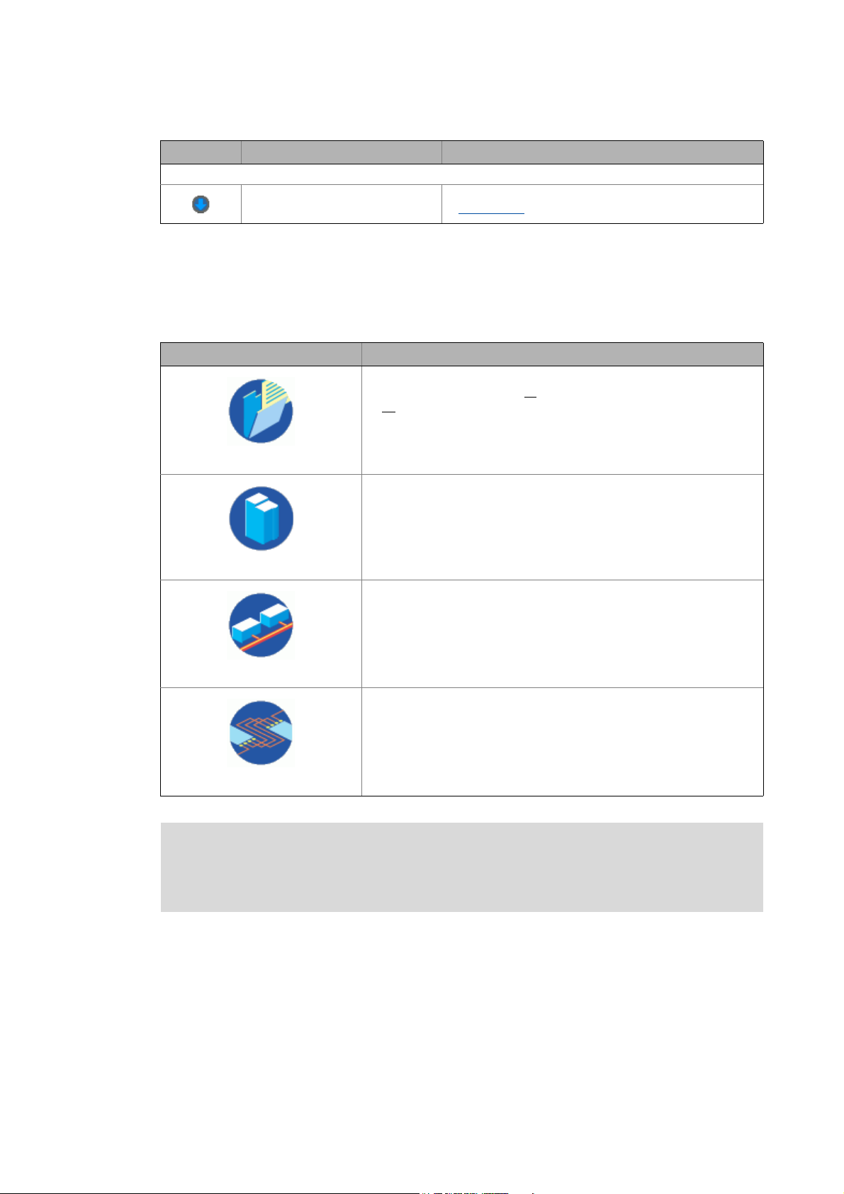
Chapter Contents
Safety instructions
User interface ( 13) ...describes the user interface structure in the »Engineer«
Getting started: creating a project
( 30)
Establishing an online connection
( 75)
Device functions with active online
connection ( 98)
Defining the system functionality
( 128)
Inserting & configuring a network
( 202)
( 12) ...contains safety instructions which have to be observed if you want to
commission a controller or a system by means of the »Engineer«.
...describes how to create a project in the »Engineer«.
... describes how to establish an online connection to one or several
devices.
... describes how to execute the control functions of a device and a
parameter set/program transfer between the device and the
»Engineer«.
...describes the diagnostics options when an online connection has been
established to the device.
...describes how to define the functionality of your entire system in the
»Engineer«.
...describes how to add networks to the project and configure them to
ensure the communication between the devices of the system.
Lenze · Engineer · 2.13 EN - 10/2014 9
Page 10
About this documentation
Conventions used
_ _ _ _ _ _ _ _ _ _ _ _ _ _ _ _ _ _ _ _ _ _ _ _ _ _ _ _ _ _ _ _ _ _ _ _ _ _ _ _ _ _ _ _ _ _ _ _ _ _ _ _ _ _ _ _ _ _ _ _ _ _ _ _
1.1 Conventions used
This documentation uses the following conventions to distinguish between different types of
information:
Type of information Highlighting Examples/notes
Spelling of numbers
Decimal separators Point The decimal point is generally used.
For example: 1234.56
Text
Version information Text colour blue All pieces of information that only apply to or from a specific
Program name » « »Engineer«...
Window italics The Message window... / the Options dialog box...
Variable names Setting bEnable to TRUE...
Control element bold The OK button ... / The Copy command ... / The Properties tab
Sequence of menu
commands
Shortcut <bold> Use <F1> to open the online help.
Hyperlink underlined
Symbols
Page reference ( 10) Reference to further information: Page number in PDF file.
Step-by-step instructions
software version of the inverter are highlighted
correspondingly in this documentation.
Example: This function extension is available from software
version V3.0!
... / The Name input field ...
If several commands must be used in sequence to carry out a
function, the individual commands are separated by an
arrow: Select File
If a shortcut is required for a command to be executed, a "+"
has been put between the key identifiers: With
<Shift>+<ESC> ...
Reference to further information: Hyperlink to further
information.
Step-by-step instructions are marked by a pictograph.
Open to...
10
Lenze · Engineer · 2.13 EN - 10/2014
Page 11
About this documentation
Definition of notes used
_ _ _ _ _ _ _ _ _ _ _ _ _ _ _ _ _ _ _ _ _ _ _ _ _ _ _ _ _ _ _ _ _ _ _ _ _ _ _ _ _ _ _ _ _ _ _ _ _ _ _ _ _ _ _ _ _ _ _ _ _ _ _ _
1.2 Definition of notes used
The following signal words and symbols are used in this documentation to indicate dangers and
important information:
Safety instructions
Structure of the safety instructions:
Danger!
(characterises the type and severity of danger)
Note
(describes the danger and informs how to prevent dangerous situations)
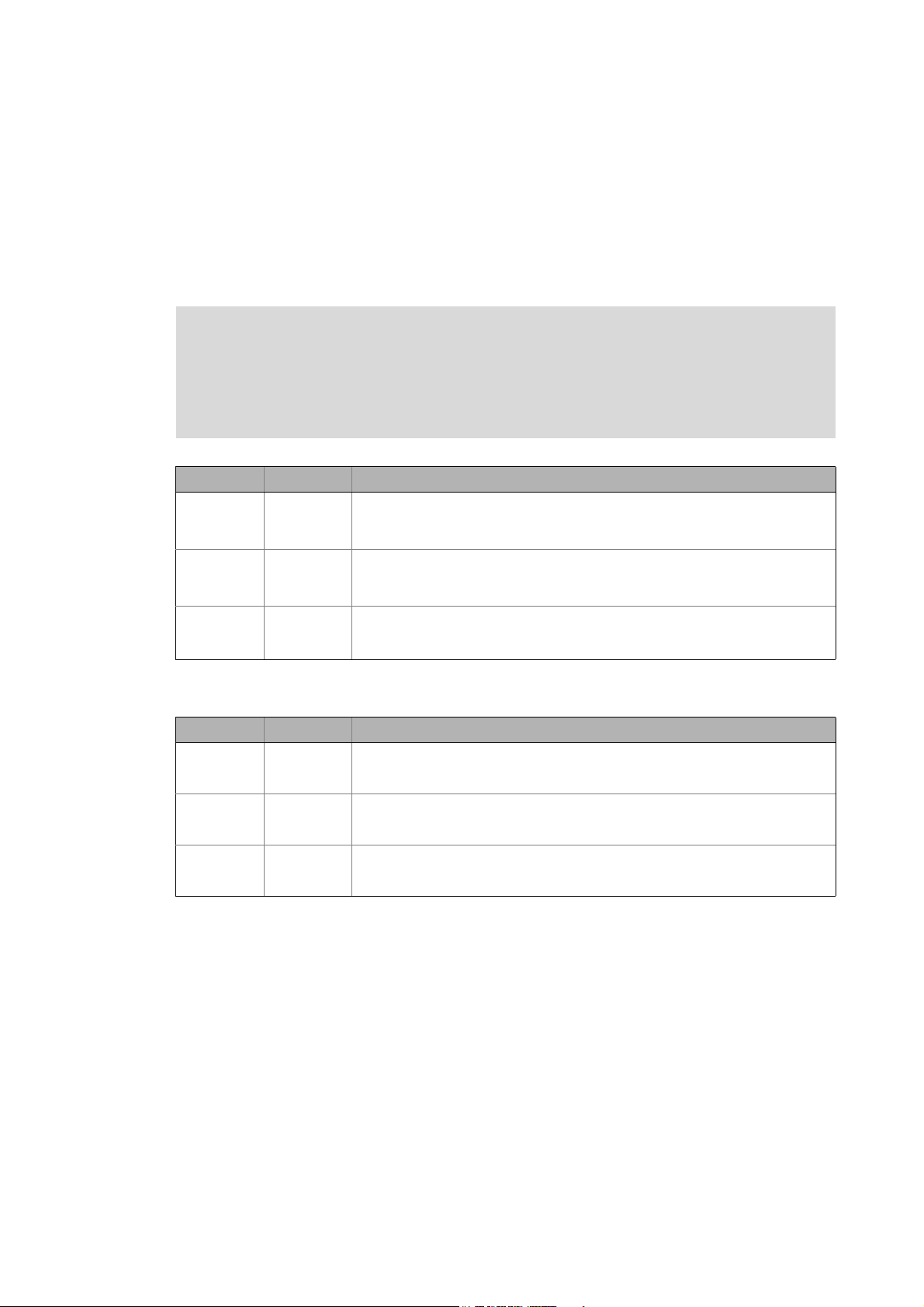
Pictograph Signal word Meaning
Danger! Danger of personal injuries through dangerous electrical voltage
Danger! Danger of personal injury through a general source of danger
Stop! Danger of material damage
Application notes
Reference to an imminent danger that may result in death or serious personal
injury unless the corresponding measures are taken.
Reference to an imminent danger that may result in death or serious personal
injury unless the corresponding measures are taken.
Indicates a potential danger that may lead to material damage unless the
corresponding measures are taken.
Pictograph Signal word Meaning
Note! Important note to ensure troublefree operation
Tip! Useful tip for easy handling
Reference to another document
Lenze · Engineer · 2.13 EN - 10/2014 11
Page 12

Safety instructions
_ _ _ _ _ _ _ _ _ _ _ _ _ _ _ _ _ _ _ _ _ _ _ _ _ _ _ _ _ _ _ _ _ _ _ _ _ _ _ _ _ _ _ _ _ _ _ _ _ _ _ _ _ _ _ _ _ _ _ _ _ _ _ _
2 Safety instructions
Please observe the following safety instructions when you want to commission a controller or
system using the »Engineer«.
Read the documentation supplied with the controller or the individual components of
the system carefully before you start to commission the devices with the »Engineer«!
The device documentation contains safety instructions which must be observed!
Danger!
If required, systems with integrated controllers have to be equipped with additional
monitoring and protective equipment in accordance with the safety regulations valid in
each case (e.g. law on technical equipment, regulations for the prevention of accidents),
so that an impermissible operating status does not endanger persons or equipment.
During commissioning persons must keep a safe distance from the motor or the
machine parts driven by the motor. Otherwise there would be a risk of injury by the
moving machine parts.
Stop!
If you change parameters in the »Engineer« while the controller is connected online, the
changes will be directly accepted by the controller!
An incorrect parameterisation can result in unpredictable motor movements. By an
unintentional direction of rotation, too high speeds or jerky operation, powered
machine parts can be damaged!
12 Lenze · Engineer · 2.13 EN - 10/2014
Page 13
User interface
_ _ _ _ _ _ _ _ _ _ _ _ _ _ _ _ _ _ _ _ _ _ _ _ _ _ _ _ _ _ _ _ _ _ _ _ _ _ _ _ _ _ _ _ _ _ _ _ _ _ _ _ _ _ _ _ _ _ _ _ _ _ _ _
3 User interface
Note!
Different licence levels are available for the Engineering tools of Lenze. Depending on
the licence level used, the functional range varies on the user interface. Current
information can be found at:
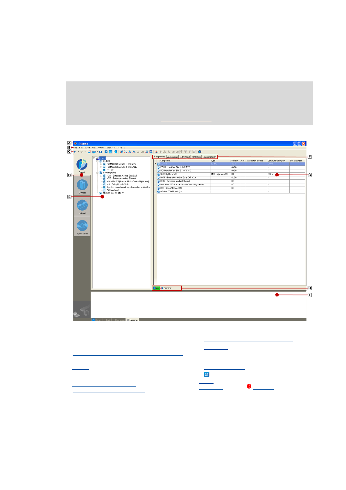
The user interface is principally divided into the following areas:
http://www.Lenze.com
Title bar/available licence level Tabs (context-dependent)
Parameterising & configuring the devices
Menu commands
Menu reference - Overview of the menu commands
( 257)
Toolbar
Project view bar: Filtering the project tree
Project structure (project tree)
Getting started: creating a project
( 15) Status information ( 23)
( 17) Monitor: Monitoring parameters ( 24) /
( 18)
( 30)
Workspace
Create
User menu
without illustration: Wizards
( 21)
( 27) /
( 170) / Messages ( 27)
( 132)
( 28)
Lenze · Engineer · 2.13 EN - 10/2014 13
Page 14

User interface
_ _ _ _ _ _ _ _ _ _ _ _ _ _ _ _ _ _ _ _ _ _ _ _ _ _ _ _ _ _ _ _ _ _ _ _ _ _ _ _ _ _ _ _ _ _ _ _ _ _ _ _ _ _ _ _ _ _ _ _ _ _ _ _
Tip!
In order to increase the workspace
view bar
• Alternatively the settings of the Project view bar 3 can be executed via the menu
on the left side or mask them out.
command ExtrasOptions in the Environment tab. Options for the representation/
project memory location ( 29)
, you can reduce the size of the buttons of the project
14 Lenze · Engineer · 2.13 EN - 10/2014
Page 15
User interface
Toolbar
_ _ _ _ _ _ _ _ _ _ _ _ _ _ _ _ _ _ _ _ _ _ _ _ _ _ _ _ _ _ _ _ _ _ _ _ _ _ _ _ _ _ _ _ _ _ _ _ _ _ _ _ _ _ _ _ _ _ _ _ _ _ _ _
3.1 Toolbar
Via the Toolbar frequently used functions can be accessed without the need to use the menu
commands.
Note!
Depending on the project context, different icons can be activated or are deactivated
(greyed out).
• Some icons, for instance, are only available when a controller is selected.
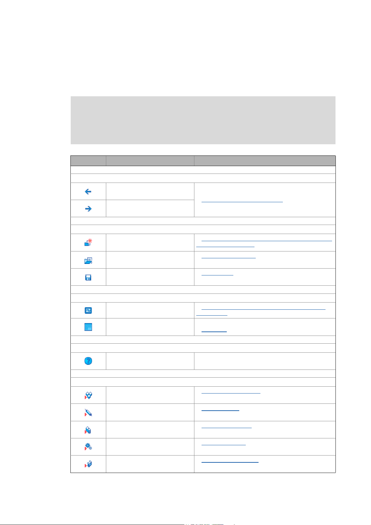
Icon/button Menu command Function
History of the operating steps (back/next)
- One step forwards or backwards in the history of the
-
previously selected elements.
History of the preselected elements
( 19)
Managing projects
New project...
File
File
Open...
Save
File
Configure user interfaces
- Adapt monitor window: Show parameters graphically
- Maximise or minimise workspace
Call context help
- Display online help in the context of the selected device
Inserting project elements
Insert
System module
Axis
Insert
Updating projects while opening them: Adapting project
file from previous version ( 39)
Opening the project file
Save a project
(instruments) ( 25)
Workspace
Inserting system modules
Inserting an axis
( 42)
( 21)
( 38)
( 47)
( 48)
Component
Insert
Gearbox
Insert
Device module
Insert
Lenze · Engineer · 2.13 EN - 10/2014 15
Inserting components
Inserting a gearbox
Inserting device modules
( 51)
( 67)
( 57)
Page 16
User interface
Toolbar
_ _ _ _ _ _ _ _ _ _ _ _ _ _ _ _ _ _ _ _ _ _ _ _ _ _ _ _ _ _ _ _ _ _ _ _ _ _ _ _ _ _ _ _ _ _ _ _ _ _ _ _ _ _ _ _ _ _ _ _ _ _ _ _
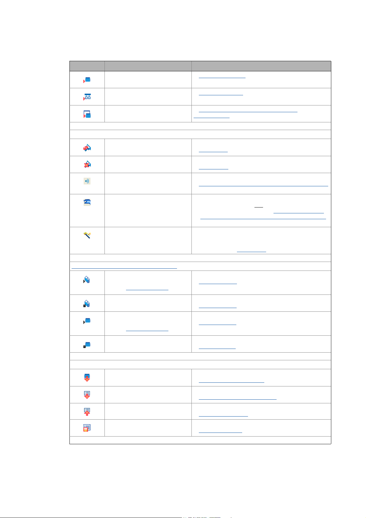
Icon/button Menu command Function
InsertApplication
Inserting application
( 55)
Network
Insert
Machine application
Insert
Going online/offline
OnlineGo online
Online
Go offline
Online
Optical location
Manual control
Online
- Commissioning wizard for guided commissioning of
Device functions with active online connection
OnlineEnable controller
Inserting a network
Inserting a machine application with a port
interconnection ( 174)
Establish a connection to a device
Going online
Break the connection to a device
Going offline
Device search function (signalling via device LEDs)
Optical tracking - device identification within the machine
( 107)
Manual control (available depending on the device)
• Can only be activated if one
device supports this function. Manual control of the
motor direction of rotation: Rotating the axes manually
( 109)
controllers of the 8400 device series
• ... is available in case there is an active online connection
to the device. Going online
Enable device (cancel controller inhibit)
Enable controller
( 207)
( 77)
( 96)
device is selected and the
( 100)
Safety instructions ( 12)
Inhibit controller
Online
Online
Start application
Safety instructions ( 12)
Stop application
Online
Application / parameter transfer
Online
Download program
Online
Download parameter set
Online
Upload parameter set
Online
Save parameter set
Inhibit device (set controller inhibit)
Inhibit controller
Start application in the device
Start application
Stop application in the device
Stop application
Download application to the device
Download program to device
Download parameter set to the device
Download parameter set to device
Upload parameter set
Upload parameter set
Save parameter set in the device safe against mains failure
Save parameter set
( 101)
( 101)
( 101)
( 103)
( 105)
( 106)
( 107)
16
Lenze · Engineer · 2.13 EN - 10/2014
Page 17
User interface
Project view bar: Filtering the project tree
_ _ _ _ _ _ _ _ _ _ _ _ _ _ _ _ _ _ _ _ _ _ _ _ _ _ _ _ _ _ _ _ _ _ _ _ _ _ _ _ _ _ _ _ _ _ _ _ _ _ _ _ _ _ _ _ _ _ _ _ _ _ _ _
Icon/button Menu command Function
Build project (compile)
Build project
Tools
3.2 Project view bar: Filtering the project tree
Via the following buttons/icons in area of the application window you can filter the view of the
Project tree:
Button Representation in the project tree
Show Project tree in the Project view.
• This button serves to show all
•All
project elements can be edited.
Build project (individual project elements or whole project).
Build project ( 76)
available project elements.
Project
Devices
Network
Applications
Note!
Filter Project tree in the Device view
• The project tree only shows the root element and the devices inserted.
Details (like for example interfaces) are masked out.
Filter project tree in the Network view
• The project tree only shows the root element and the networks inserted.
Filter Project tree in the Application view
• The project tree only shows the root element and the applications that
are inserted in the project.
In order to be able to completely edit the project, you have to be in the Project view
(Project button in the Project view bar).
• Depending on the button selected in the Project view bar, the available icons in the Toolbar, the
elements shown in the Project view, and the Workspace change.
Lenze · Engineer · 2.13 EN - 10/2014 17
Page 18
User interface
Project structure (project tree)
_ _ _ _ _ _ _ _ _ _ _ _ _ _ _ _ _ _ _ _ _ _ _ _ _ _ _ _ _ _ _ _ _ _ _ _ _ _ _ _ _ _ _ _ _ _ _ _ _ _ _ _ _ _ _ _ _ _ _ _ _ _ _ _
Representing the project view bar in a reduced size/masking it out
Tip!
In order to increase the workspace, you can use the context menu (right-hand mouse
button) to reduce the size of the buttons in the project view bar or mask them out.
Alternatively, the settings of the project view bar can be executed via the menu command
ExtrasOptions in the Environment. Options
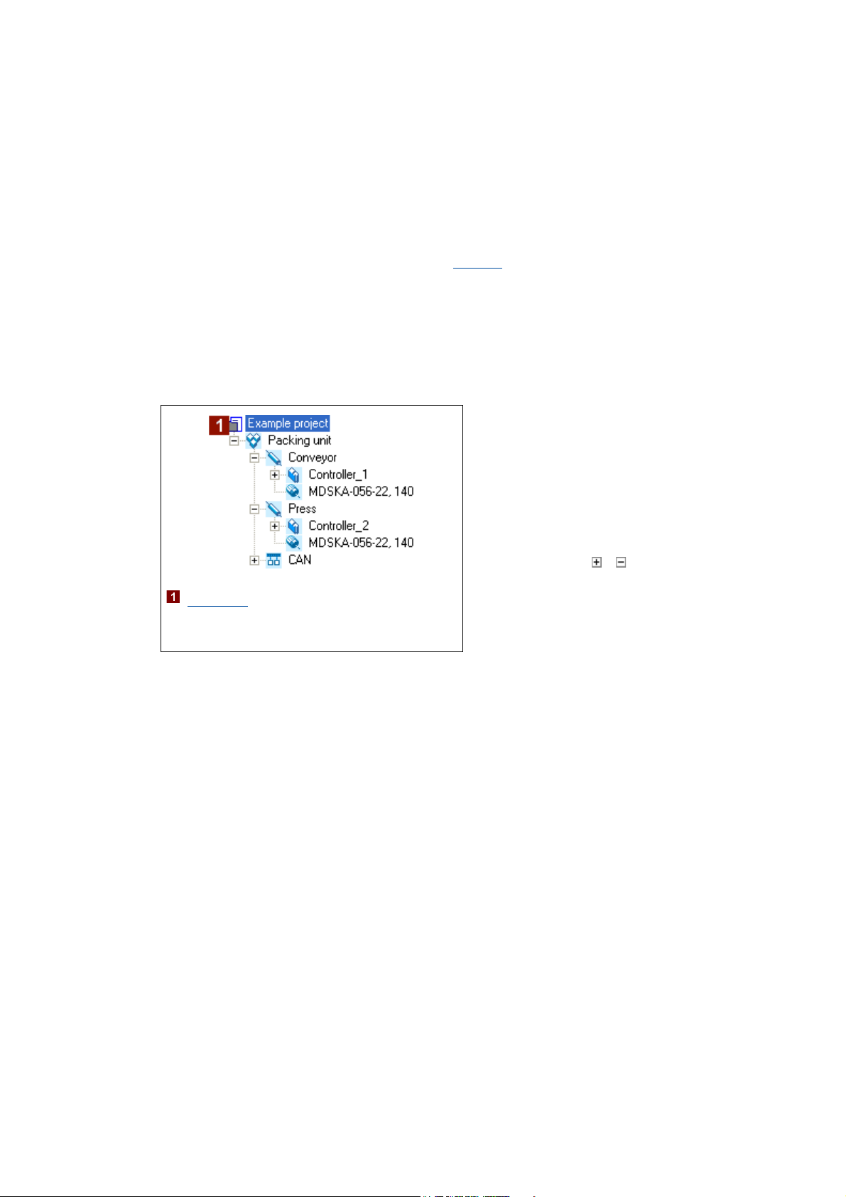
3.3 Project structure (project tree)
Similar to the folder view in the Windows Explorer, the project structure shows the individual
machine components in the form of a tree topology:
( 99)
• If you select a project element and then
change to the workspace, the project
element is still shown on a grey
background and is underlined at the same
time.
• Like this you can clearly see which
project element the active workspace
belongs to.
• By clicking the / icons, sub-elements
can be shown / hidden.
[3-1] Example for the hierarchical representation of the project structure in the Project tree
: Project root
•In the workspace, the properties and
settings of the currently selected element/
device are shown and can be edited there.
Tip!
You can alter the width and height of the Project view by using the mouse pointer to shift
the screen divider between the Project view and the Workspace or between the Project view
and the Message window.
By clicking with the right-hand mouse button, you can open a Context menu containing
functions relevant to the elements.
18
Lenze · Engineer · 2.13 EN - 10/2014
Page 19

User interface
Project structure (project tree)
_ _ _ _ _ _ _ _ _ _ _ _ _ _ _ _ _ _ _ _ _ _ _ _ _ _ _ _ _ _ _ _ _ _ _ _ _ _ _ _ _ _ _ _ _ _ _ _ _ _ _ _ _ _ _ _ _ _ _ _ _ _ _ _
3.3.1 History of the preselected elements
All elements selected in the Project view during project processing are stored in a "history".
Note!
The history is emptied automatically when the project is closed, i.e. the history is always
empty when you open a project.
The / buttons in the Toolbar jump to the project element selected previously / next.
Tip!
If the Project tree contains multiple devices, use to return to the component edited last
(e.g. a controller).
• If you click the arrow, , next to the / buttons, a selection list including the elements
selected last is available.
• Every entry is provided in the following form: "project name: element name".
3.3.2 General editing functions in the project view
The following processing functions apply to all elements in the Project view.
Drag element (cut & paste)
Duplicate element (copy & paste) ( 20)
Delete element ( 20)
Rename element ( 20)
Drag element (cut & paste)
1. Select the element to be shifted including all subelements.
2. Click and hold the element with your left mouse button and drag it to the desired position. The
current position of the element is displayed in one of the following manners:
• Highlighting the respective element:
The element to be shifted becomes the sub-element of the highlighted element. This behaviour
corresponds to the following command chain: EditCut, and then EditPaste.
( 19)
Lenze · Engineer · 2.13 EN - 10/2014 19
Page 20

User interface
Project structure (project tree)
_ _ _ _ _ _ _ _ _ _ _ _ _ _ _ _ _ _ _ _ _ _ _ _ _ _ _ _ _ _ _ _ _ _ _ _ _ _ _ _ _ _ _ _ _ _ _ _ _ _ _ _ _ _ _ _ _ _ _ _ _ _ _ _
• Element representation as horizontal bar:
The shifted element is positioned as desired between the two adjacent elements. The order of
elements of the same level can be changed in the Project tree:
or
1. Select the element to be shifted including all subelements.
2. Select menu command EditCut.
3. Select the element into which the element cut before is to be pasted.
4. Select menu command EditInsert.
Duplicate element (copy & paste)
1. Select the element which is to be copied including all subelements.
2. Select menu command EditCopy.
3. Select the element into which the element copied before is to be pasted.
4. Select menu command EditInsert.
Delete element
1. Select the element to be deleted including all subelements.
2. Select menu command EditDelete or press the <Del> button in order to delete the element
selected.
Rename element
1. Select the element to be renamed.
2. Select menu command EditRename or press the <F2> function key.
3. Enter new name.
4. Press the <input key> to accept the new name.
3.3.3 Shortcuts in the project view
20
Tip!
As an alternative to directly selecting elements with the help of the mouse pointer, you can
use keyboard shortcuts (for example, if you are running »Engineer« on a notebook). This
enables faster movement within the Project view in order to select elements for editing.
You can use the following shortcuts for navigating within the Project view if an element is focused
on in the Project view:
Lenze · Engineer · 2.13 EN - 10/2014
Page 21
User interface
Workspace
_ _ _ _ _ _ _ _ _ _ _ _ _ _ _ _ _ _ _ _ _ _ _ _ _ _ _ _ _ _ _ _ _ _ _ _ _ _ _ _ _ _ _ _ _ _ _ _ _ _ _ _ _ _ _ _ _ _ _ _ _ _ _ _
Shortcut Function
<PG UP> Browsing upwards in the Project tree.
<PG DN> Browsing downwards in the Project tree.
<UP ARROW> Selection of the next element up.
<DOWN ARROW> Selection of the next element down.
<LEFT ARROW> Depending on the symbol shown in front of the element:
/ Selection of the higher-level/lower-level element in the hierarchy.
<RIGHT ARROW Depending on the symbol shown in front of the element:
/ Selection of the higher-level/lower-level element in the hierarchy.
<BACKSPACE> Selection of the higher-level element in the hierarchy in each case.
<POS1> Selection of the first project element.
<END> Selection of the last (shown) project element.
Tip!
In order to focus on an element in the Project view, click on a project element or press the
<Tab> key until you reach the desired element.
3.3.4 Project root
The project root is the topmost element in the Project tree (root element). The name
corresponds to the file name of the project.
• If the project root is selected, the tabs including general project properties are visible in the
workspace.
Tab Function
Components Tabulates all components inserted into the project.
Applications Tabulates all applications inserted into the project.
Data logger The data logger serves to record the temporal course of parameter values
Documentation Provides the opportunity to enter detailed information on the project and
Protection Settings for protecting the safe configuration
• The properties of the respective component are visible (device type,
firmware version, communication path) as well as the structural
integration in the form of system modules/axes.
• The assignment to system modules/axes is visible.
and display it as a line diagram. Data logger
• Note: For using this function, an online connection to the desired device
is required!
the projected machine plant.
• Notes and file attachments can be added to each project element.
Documentation - Add project details
• Assign a project-related password for protecting the safe configuration
(tab Safe configuration, safe parameters. Protecting safe parameters -
project-related password entry ( 74)
( 111)
( 71)
3.4 Workspace
The workspace (area ) has various tabs which show the properties and settings of the project
element currently selected in the project tree. A project element can be for instance a device: Servo
Drives 9400 HighLine.
Lenze · Engineer · 2.13 EN - 10/2014 21
Page 22
User interface
Workspace
_ _ _ _ _ _ _ _ _ _ _ _ _ _ _ _ _ _ _ _ _ _ _ _ _ _ _ _ _ _ _ _ _ _ _ _ _ _ _ _ _ _ _ _ _ _ _ _ _ _ _ _ _ _ _ _ _ _ _ _ _ _ _ _
Tip!
The representation of the tabs in the workspace depends on the selected project element /
device type.
You can alter the width and height of the Workspace by using the mouse pointer to move
the screen divider between the Project view and the Workspace or between the Workspace
and the Message window as required.
Parameterising & configuring the devices
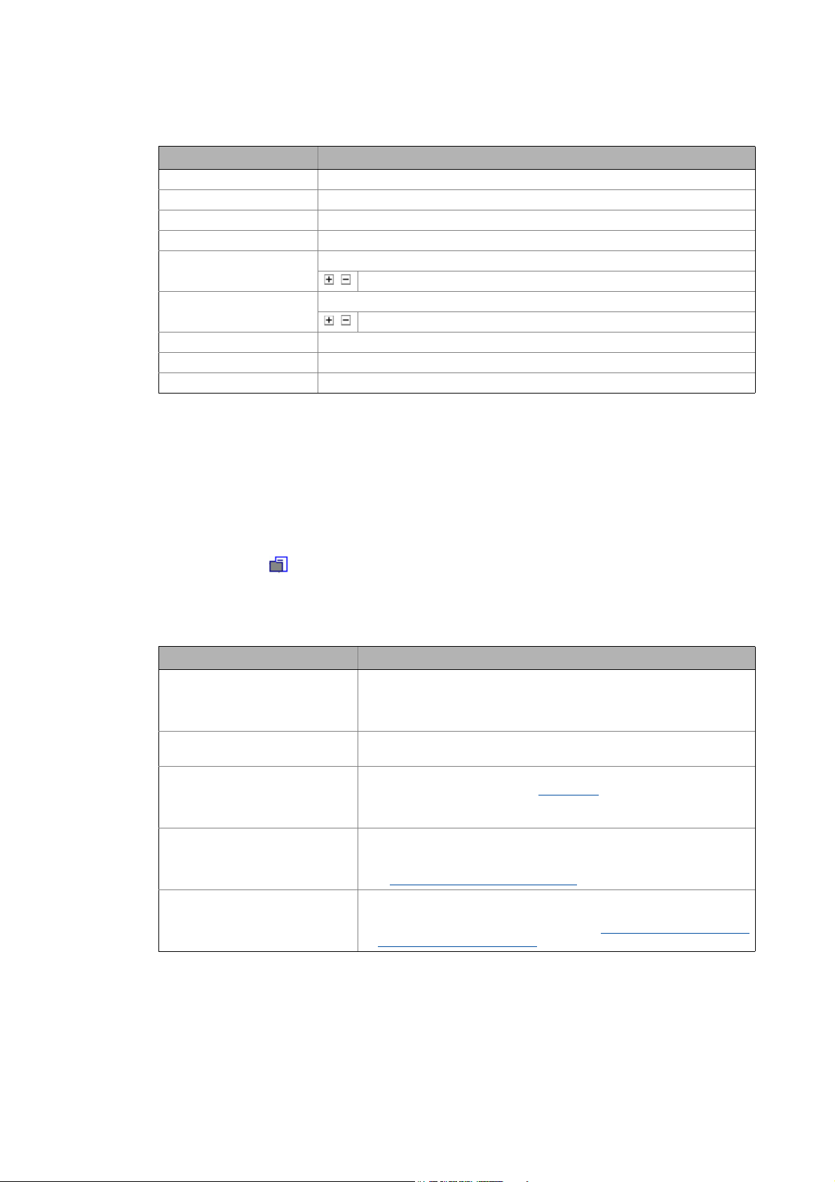
3.4.1 Displaying parameter values
Device parameter settings shown in the workspace of the »Engineer« (e.g. in the Parameters tab for
a device) are displayed with different background colours with the following meaning:
Colour Example Meaning
Offline representation
White Offline parameter
Light grey Offline display parameter
Online representation
Yellow Online parameter (value can be changed)
Pale yellow Online display parameter (read only)
Red Communication error (time-out)
( 132)
• The device is not connected "online" with the »Engineer«. The "offline" parameter
value set in the project is displayed.
• So-called "display parameters" are parameters which are only used to show
status information and actual values and which feature a read-only access.
• The device is connected "online" with the »Engineer«. The current parameter
value of the device is displayed.
• The symbol in front of a parameter value indicates that the value in the device
differs from the parameter value set in the project.
• The device is "online", i.e. connected to »Engineer«. The current parameter value
of a display parameter of the device is shown.
• Communication to a device is interrupted, the online parameter could not be
read out of the device within a certain time.
22
Lenze · Engineer · 2.13 EN - 10/2014
Page 23
User interface
Status information
_ _ _ _ _ _ _ _ _ _ _ _ _ _ _ _ _ _ _ _ _ _ _ _ _ _ _ _ _ _ _ _ _ _ _ _ _ _ _ _ _ _ _ _ _ _ _ _ _ _ _ _ _ _ _ _ _ _ _ _ _ _ _ _
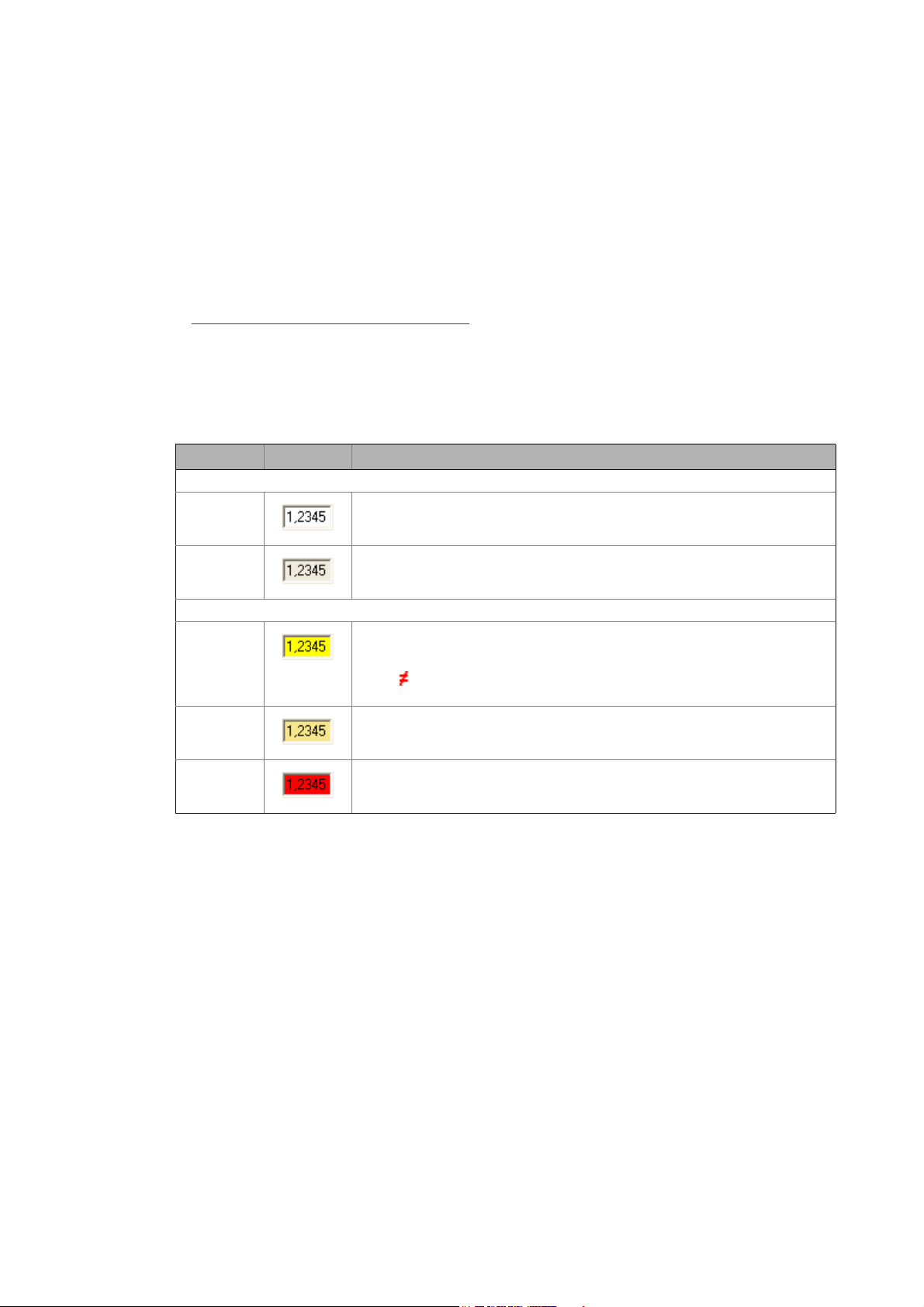
If you edit a parameter value in an input field, you can see from the colour of the text whether the
altered value has already been integrated into the project or the device and is within the valid range.
Colour Example Meaning
Black Parameter value that is within the valid range and that has already been integrated
into the project or device.
Blue Altered parameter value that has not yet been integrated into the project or the
Red Changed parameter value which is outside the valid range.
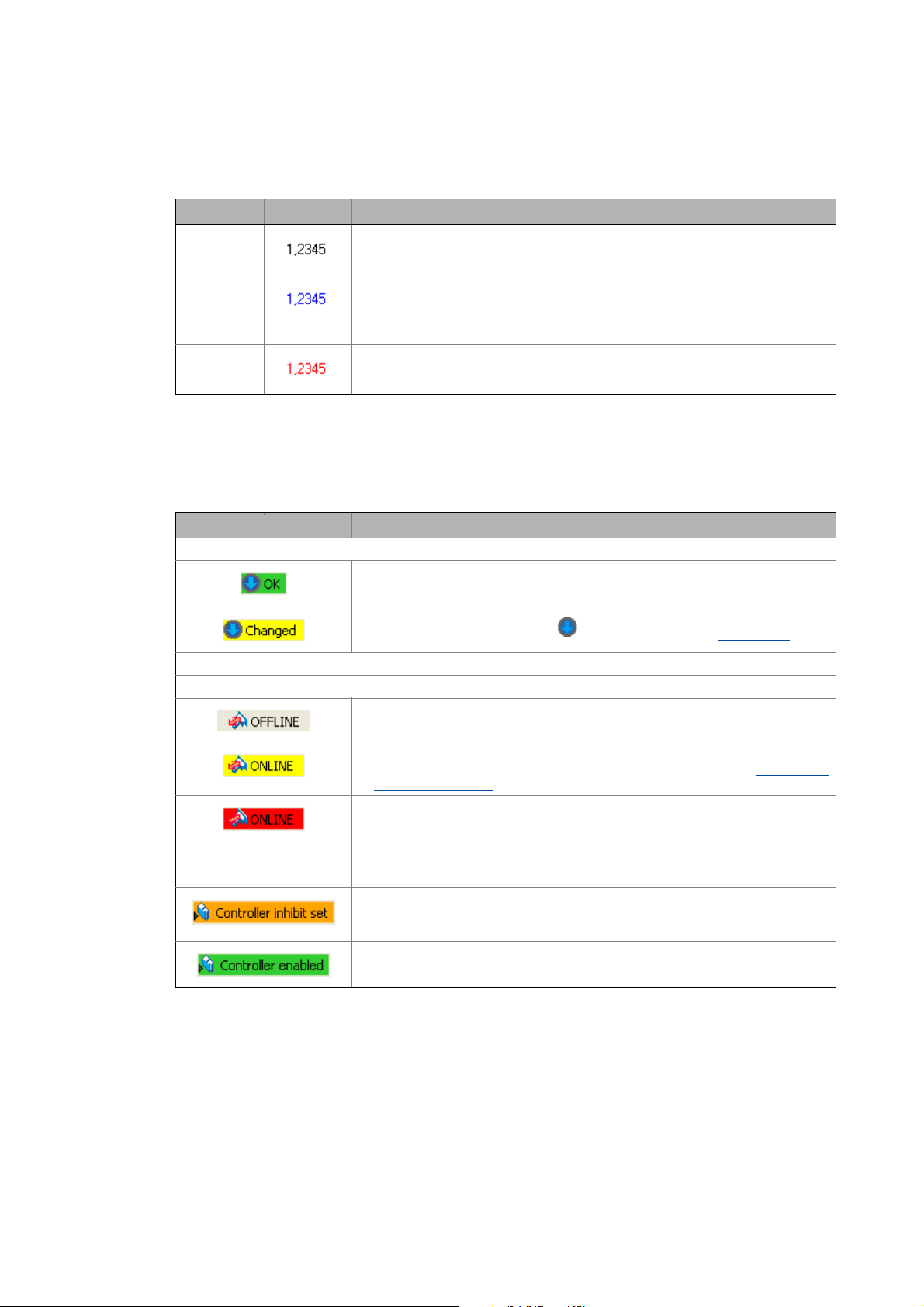
3.5 Status information
Information on the status of the project and devices/applications.
Information Meaning
Project status
Device status
device.
• By pressing the <input key>, you accept the altered value.
• You can reject the change by pressing the <ESC> key.
• You can reject the change by pressing the <ESC> key.
All project information is up to date.
• The project element selected in the Project tree does not have to be updated.
The project contains unsaved changes.
• Build the project by pressing the button in the Toolbar. Build project
The device is offline.
• No online connection to the device.
( 76)
Active online connection to the device.
• The »Engineer« communicates with device via a bus connection. Establishing
an online connection ( 75)
Active online connection is interrupted.
• An established online connection between the device and the »Engineer« is
interrupted (communication error).
DDCMP:/ Device-dependent access path
• The access path depends on the respective bus connection.
The controller is inhibited.
• The controller inhibit is set. Move the mouse pointer over the status information
of the controller in the status line to display the source of the controller inhibit.
The controller is enabled.
Depending on the device connection used, more information can be displayed in the status line, as
for instance the application status or unsaved changed of the parameter set.
Lenze · Engineer · 2.13 EN - 10/2014 23
Page 24
User interface
Monitor: Monitoring parameters
_ _ _ _ _ _ _ _ _ _ _ _ _ _ _ _ _ _ _ _ _ _ _ _ _ _ _ _ _ _ _ _ _ _ _ _ _ _ _ _ _ _ _ _ _ _ _ _ _ _ _ _ _ _ _ _ _ _ _ _ _ _ _ _
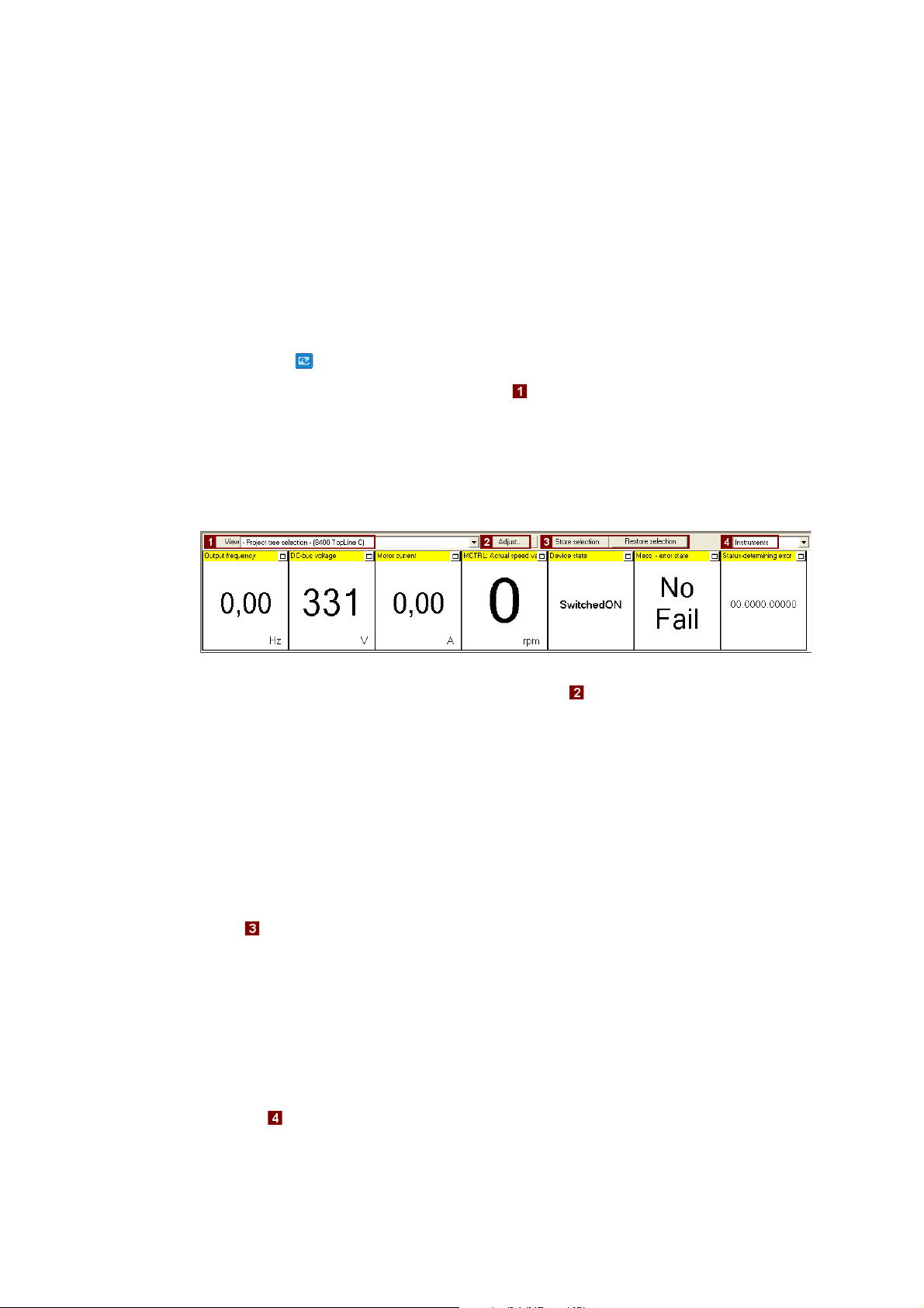
3.6 Monitor: Monitoring parameters
In the Monitor area below the project view and workspace, the parameters of a device to be selected
can be displayed as display parameters. This is reasonable, for instance, for monitoring certain
parameters for diagnostic purposes.
3.6.1 Show monitor window: Accept parameters/type of presentation
How to show the monitor window:
1. Click the Monitor tab at the bottom of the user window.
2. Select the desired monitor window in the View list field:
• -Project tree selection-: The monitor window always shows the parameters for device
currently marked in the project tree.
• System: Multi-device monitor window with your compiled parameters for several
devices of the automation system.
• Monitor window for a certain device. This leaves the focus on this device although a
different device has been marked in the project tree.
•The monitor window is preconfigured with display parameters. The display parameters visible
in the monitor window can be changed by clicking the Adjust button.
Tip!
Increase individual display parameter: By clicking the window symbol in the top right
display field, you show a display parameter across the entire width of the monitor window.
For reducing it again, click the displayed window icon . This serves to show all display
parameters again in the monitor window.
Using the parameter compilation for another device
Using the Store selection and Restore selection buttons, you can use the parameter compilation
of a monitor window for another device in the same project.
• After a monitor window has been created with device 1, click the Store selection button.
• Mark the desired device 2 in the project tree the application is to apply to as well.
•Click the Restore selection button to accept the parameter selection for the monitor window for
device 2.
Change type of presentation: Graphic or tabular
24
The list field changes the type of presentation: Graphic as Instruments or tabular as single-
column/two-column list.
Lenze · Engineer · 2.13 EN - 10/2014
Page 25
User interface
Monitor: Monitoring parameters
_ _ _ _ _ _ _ _ _ _ _ _ _ _ _ _ _ _ _ _ _ _ _ _ _ _ _ _ _ _ _ _ _ _ _ _ _ _ _ _ _ _ _ _ _ _ _ _ _ _ _ _ _ _ _ _ _ _ _ _ _ _ _ _
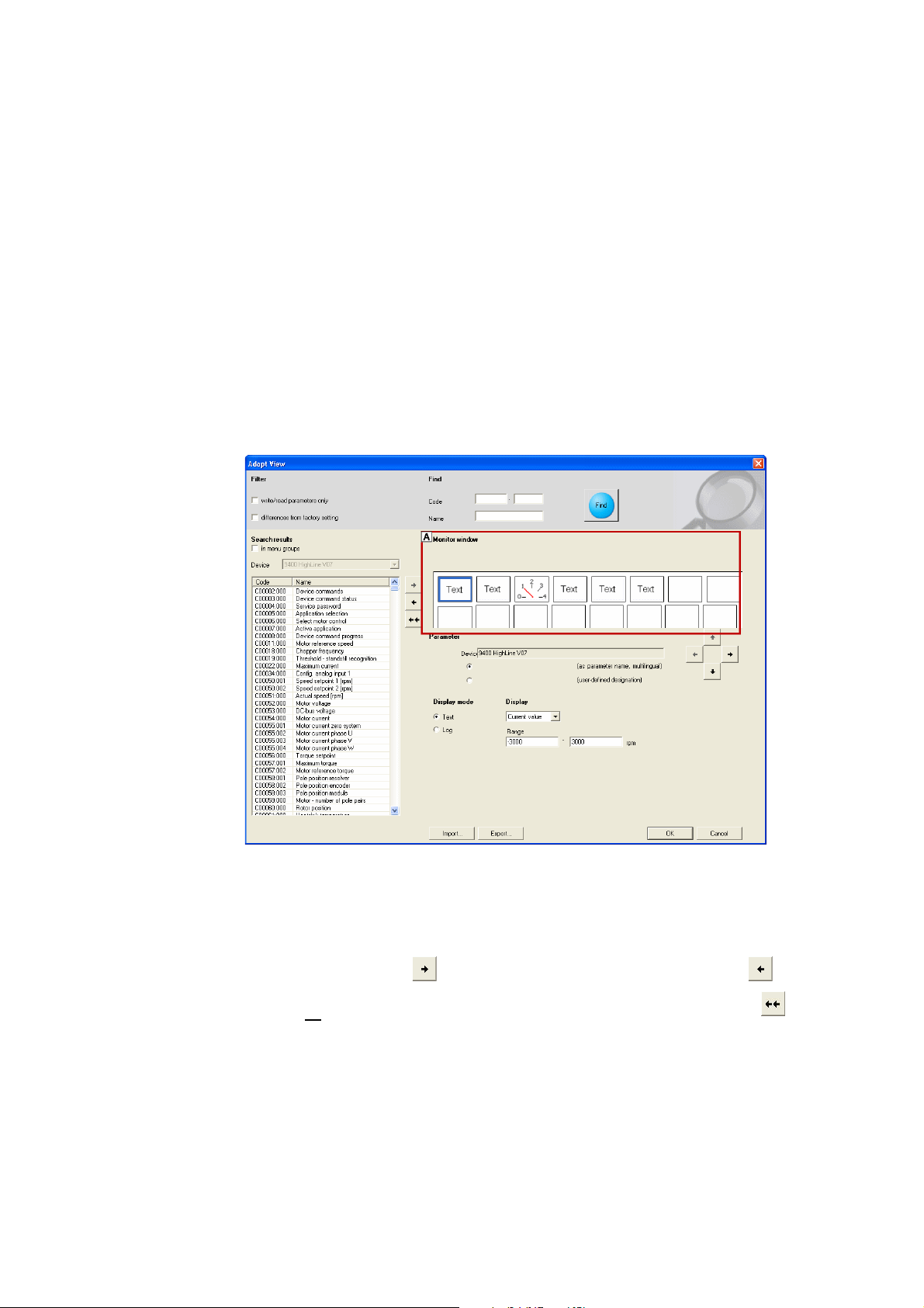
3.6.2 Adapt monitor window: Show parameters graphically (instruments)
The instruments option serves to present your requested parameters graphically.
Tip!
Any value from the parameter list (All parameters tab) of a device can be transferred to the
monitor window via right-click: Command: Add to monitor window
How to add the parameters to the monitor window:
1. Select the desired monitor window:
• Select the monitor window to be configured in the View list field (above the monitor
window.
2. Click the Adapt button:
• Click the display field you want to configure in the area. The currently selected display field is
highlighted by a blue frame.
3. In the area , select the parameter from all parameters of the device ...
... to be displayed in the display field of the monitor window (area ).
...by clicking the arrow key /undoing the selection by using the arrow key . In order
to remove all
• In order that only certain parameters are visible in the area , activate the corresponding
filter options.
• Activate the in menu groups control field to arrange the parameters according to menu
groups.
4. Repeat the steps 1 to 4 to display more parameters in the display fields in area (one
parameter each per display field is possible).
parameters from the monitor window, use the double arrow key .
Lenze · Engineer · 2.13 EN - 10/2014 25
Page 26
User interface
Monitor: Monitoring parameters
_ _ _ _ _ _ _ _ _ _ _ _ _ _ _ _ _ _ _ _ _ _ _ _ _ _ _ _ _ _ _ _ _ _ _ _ _ _ _ _ _ _ _ _ _ _ _ _ _ _ _ _ _ _ _ _ _ _ _ _ _ _ _ _
5. In the field, the Import/Export buttons serve to import/export composed monitor views.
This serves, for instance, to use them in another »Engineer« project.
6. Press OK to transfer the selection to the monitor window.
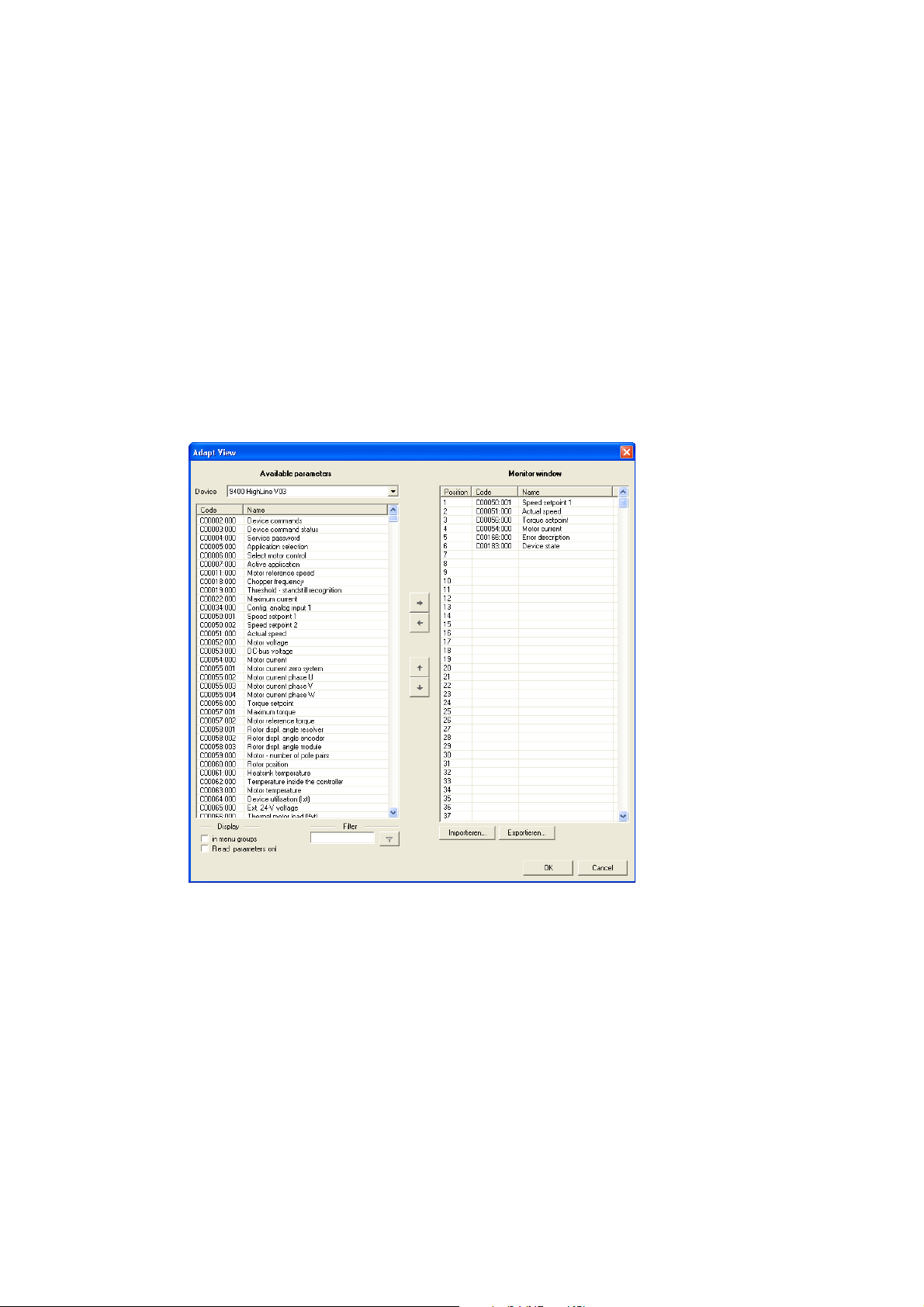
3.6.3 Adapt monitor window: Present parameters graphically (list)
The instruments option serves to present your requested parameters in table form in the monitor
window.
How to add the parameters to the monitor window:
1. In the View list field, select the Monitor window to be configured.
2. Click the Adapt button to open the Adapt view dialog box.
3. Go to area and select the parameters to be transferred to the monitor window.
• Multi-selection of parameters shown one above the other: Hold down the <CTRL> key
and highlight the parameters.
• Multi-selection of individual parameters: Hold down the <SHIFT> key and highlight the
desired parameters individually.
• In order that only certain parameters are visible in the area, optionally activate the
corresponding filters .
• Activate the in menu groups control field to arrange the parameters according to menu
groups.
26
Lenze · Engineer · 2.13 EN - 10/2014
Page 27
User interface
Create
_ _ _ _ _ _ _ _ _ _ _ _ _ _ _ _ _ _ _ _ _ _ _ _ _ _ _ _ _ _ _ _ _ _ _ _ _ _ _ _ _ _ _ _ _ _ _ _ _ _ _ _ _ _ _ _ _ _ _ _ _ _ _ _
4. Select the highlighted parameters (area ) by using the arrow key /undoing the
5. In the field, the Import/Export buttons serve to import/export composed monitor views.
6. PressOk to add the selection to the monitor window.
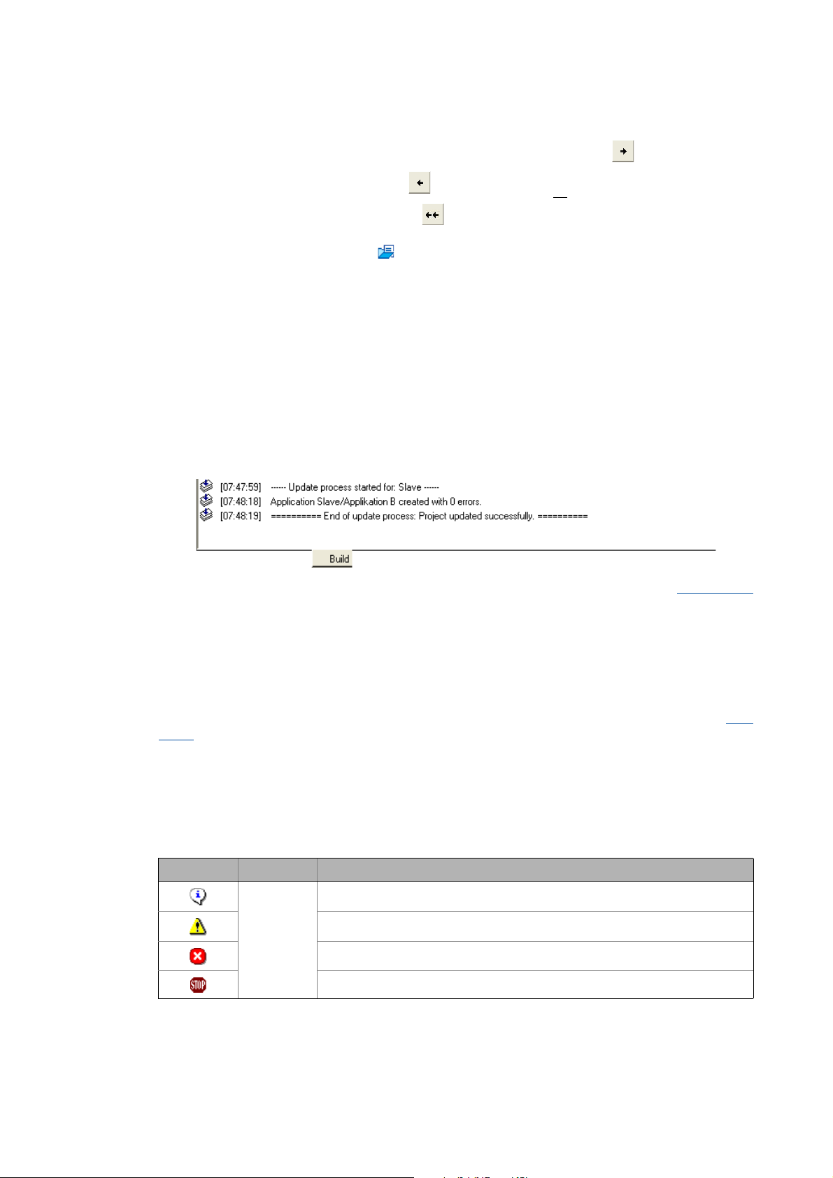
3.7 Create
The Build tab shows information on the individual creation and updating processes. Build project
( 76)
selection by using the arrow key . In order to remove all
window, use the double arrow key .
As an alternative, press the button to open a GDC file which includes the required
parameter selection.
• Field shows the parameters selected for display.
•Press OK.
This serves, for instance, to use them in another »Engineer« project.
parameters from the monitor
3.8 User menu
The User menu tab shows the selection of parameters compiled by the user.
More information on how to create a user menu can be found in the following section: User
menu ( 170)
3.9 Messages
The Message window displays status and error messages relating to an executed program operation
or the current status of the program.
Icon Time stamp Text
Context menu
The following commands can be called in the message window via right-click:
[hh.mm.ss] Information text
Note
Error text
Program error text
Lenze · Engineer · 2.13 EN - 10/2014 27
Page 28
User interface
Wizards
_ _ _ _ _ _ _ _ _ _ _ _ _ _ _ _ _ _ _ _ _ _ _ _ _ _ _ _ _ _ _ _ _ _ _ _ _ _ _ _ _ _ _ _ _ _ _ _ _ _ _ _ _ _ _ _ _ _ _ _ _ _ _ _
Command Function
Delete Delete all messages in the message window.
Display Submenu to select the elements to be displayed.
Copy list Copy all messages to the clipboard.
Copy message Copy the selected message to the clipboard.
Tip!
Using the mouse pointer, the height of the Message window can be changed by dragging
the screen divider between Workspace and Message window up or down.
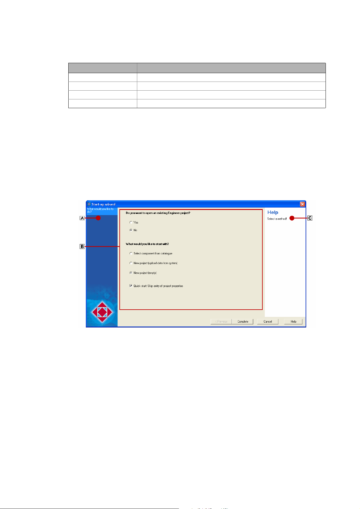
3.10 Wizards
The »Engineer« is provided with several "wizards", e.g. for creating a project or setting up and
configuring a network.
• The wizards are structured as follows. Select step by step the desired settings:
•Area shows within which step of the wizard you are right now.
•Area contains the main dialog box for entering the data and selecting the desired options.
•Areadisplays further information and input requests for the respective step.
28
Lenze · Engineer · 2.13 EN - 10/2014
Page 29
User interface
Options for the representation/project memory location
_ _ _ _ _ _ _ _ _ _ _ _ _ _ _ _ _ _ _ _ _ _ _ _ _ _ _ _ _ _ _ _ _ _ _ _ _ _ _ _ _ _ _ _ _ _ _ _ _ _ _ _ _ _ _ _ _ _ _ _ _ _ _ _
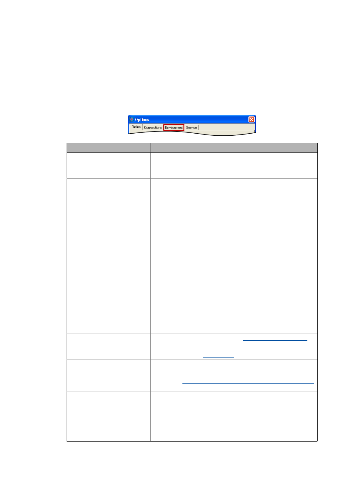
3.11 Options for the representation/project memory location
Via the ToolsOptions menu command you open the Options dialog box. In this dialog box you can
carry out general settings for the user interface in the Environment tab.
•In the Environment tab general settings can be edited.
• The settings are not a project property. Thus the settings are maintained for the following
»Engineer« projects.
Option Description
• Activate confirmation prompt
when deleting components
• Register external applications
automatically
Activate/deactivate confirmation prompt that is shown when components
are deleted.
• If this option is deactivated, the »Engineer« directly deletes the desired
component without a confirmation prompt.
Specifies that the »Engineer« automatically writes the required entries into
the Windows registry to start external programs.
• Like this the external program is registered for use in the »Engineer« and
can thus be called by the »Engineer«. Registration is effected in
accordance with the general Windows operating system standards.
• This option is activated by default.
• Change representation of the
Project view bar
• Standard memory location for
»Engineer« projects
• Representation of descriptive
texts
Example:
When a Servo Drive 9400 HighLine is updated, the »Engineer« calls the »PLC
Designer« to compile the program code which was previously created from
the function block interconnection.
On the Engineering PC several versions of »Engineer« and/or the »PLC
Designer« can be installed. When the option is activated, the »Engineer«
automatically ensures that the "suitable" (expected) »PLC Designer« version
is used for the compilation process.
Note:
If unexpected malfunction on your system occurs by thi s procedure, you can
deactivate this option.
For instance administrated access authorisation can prevent the »Engineer«
from writing into the registry.
In order to ensure that the external programs can be called by the
»Engineer«, you then have to make sure that after installing the »Engineer«
no other version of the program to be called by the »Engineer« has been
installed on your Engineering PC. Otherwise malfunction or an unexpected
response of the controller may result!
Specify the form of representation of the Project view bar: Filtering the
project tree.
•For instance, the Project view bar can be masked out to increase the size
of the Workspace. User interface
Specify the standard memory location for the creation of »Engineer«
projects
• The standard memory location can also be defined when a new project is
created. Updating projects while opening them: Adapting project file
from previous version ( 39)
Specify the type of representation of the descriptive texts.
• The standard setting is "simple and self-explanatory". By this the
respective descriptive text is reduced to the essential.
• "Formally more clearly" provides further information. Hence, the
descriptive texts are written in greater detail.
• The option for instance has a (device-independent) effect on all codes and
selection texts in the »Engineer«, which contain further descriptive texts.
• The option will become effective after an »Engineer« restart.
( 13)
Lenze · Engineer · 2.13 EN - 10/2014 29
Page 30

Getting started: creating a project
_ _ _ _ _ _ _ _ _ _ _ _ _ _ _ _ _ _ _ _ _ _ _ _ _ _ _ _ _ _ _ _ _ _ _ _ _ _ _ _ _ _ _ _ _ _ _ _ _ _ _ _ _ _ _ _ _ _ _ _ _ _ _ _
4 Getting started: creating a project
Projects are created in the »Engineer« to show the machine/system concept in the project tree. In
this project file, all parameterisation and configuration settings of the automation system are
saved.
• When you start the »Engineer«, no project is loaded at first. The Start-up wizard enables ...
• ... you to open existing projects. Opening the project file
• ... you to create new projects. Updating projects while opening them: Adapting project file
from previous version ( 39)
( 38)
30 Lenze · Engineer · 2.13 EN - 10/2014
Page 31

Getting started: creating a project
Creating a new project
_ _ _ _ _ _ _ _ _ _ _ _ _ _ _ _ _ _ _ _ _ _ _ _ _ _ _ _ _ _ _ _ _ _ _ _ _ _ _ _ _ _ _ _ _ _ _ _ _ _ _ _ _ _ _ _ _ _ _ _ _ _ _ _
4.1 Creating a new project
Create a new project using the Start-up wizard.
• Define the desired options for inserting components and project properties.
How would you like to start?
Step Option Function
What would you like to do?
• Select a component from the
catalogue
• Start the search for devices
connected
•Empty project
• Quick start guide: Skip entry of
the project properties (optionally)
Project properties
Create a project including
components from the selection lists
of the catalogues.
Creating a new project (selecting a
component from the catalogue)
( 32)
Search for devices that can be
accessed online to insert all
identified devices into the project
tree.
Creating a new project (starting
the search for devices connected)
( 34)
Creating an empty project
• Skip project properties
(properties/memory location). For
the time being the project is
named My Project and is stored at
the standard memory location.
• The quick start guide for instance
is helpful when you need projects
temporarily for testing purposes.
( 37)
Lenze · Engineer · 2.13 EN - 10/2014 31
Page 32

Getting started: creating a project
Creating a new project
_ _ _ _ _ _ _ _ _ _ _ _ _ _ _ _ _ _ _ _ _ _ _ _ _ _ _ _ _ _ _ _ _ _ _ _ _ _ _ _ _ _ _ _ _ _ _ _ _ _ _ _ _ _ _ _ _ _ _ _ _ _ _ _
Step Option Function
Product features •Project name
•Project data
•Descriptive text
Memory location • Name of the project folder
• Memory location for projects
Project properties
The project properties entered in the Start-up wizard can be edited any time later on. Project
properties ( 41)
Memory location
An »Engineer« project includes a project file (*.afs format, ) as well as other directories and files
which are stored in a project directory.
• The name and path for the project directory can be selected in the Start-up wizard.
• The memory location can be changed later. Options for the representation/project memory
location ( 29)
Define desired properties in order to
be able to clearly identify the project.
Define desired memory location.
• Optionally a standard memory
location can be defined.
4.1.1 Creating a new project (selecting a component from the catalogue)
By this procedure you create a project with components (for example controller, I/O system, etc.).
The components are chosen from the selection lists of the catalogues in the »Engineer«.
• By means of this option you can go online with the inserted controller directly after having
created the project, in order to transfer e.g. parameters.
How to create a new project with components:
1. Click the icon or select the menu command FileNew to call the start-up wizard.
Step 1 - What would you like to do?
32
Lenze · Engineer · 2.13 EN - 10/2014
Page 33

Getting started: creating a project
Creating a new project
_ _ _ _ _ _ _ _ _ _ _ _ _ _ _ _ _ _ _ _ _ _ _ _ _ _ _ _ _ _ _ _ _ _ _ _ _ _ _ _ _ _ _ _ _ _ _ _ _ _ _ _ _ _ _ _ _ _ _ _ _ _ _ _
2. Select the Select component from catalogue option.
3. Click the Next button.
4. Step 2 - Properties
Enter the corresponding properties of the project (name, order number etc.) in the input
fields.
• Enter desired Properties.
•The Name can be found later in the Project view as the name of the project element.
5. Click the Next button.
6. Step 3 - Memory location
As Project name the previously entered Project designation is suggested. If required,
correct the suggestion accordingly.
•The Project name at the same time is the name for the project directory to be created.
• Specify the storage location for the project directory in the Directory input field.
• If the folder specified is not available, it will be created.
• As an alternative you can select an existing directory in your workplace environment via
the Browse... button.
•The Always save projects here option determines the folder specified to be the standard
storage location for future »Engineer« projects. Activate this option for the central
management of all projects within the same folder.
7. Specify the storage location for the project directory in the Directory input field.
• If the specified directory does not exist, it will be created.
• As an alternative you can select an existing directory in your workplace environment via
the Browse... button.
8. Click the Next button.
9. Select the required component.
• The search results show the components available.
Lenze · Engineer · 2.13 EN - 10/2014 33
Page 34

Getting started: creating a project
Creating a new project
_ _ _ _ _ _ _ _ _ _ _ _ _ _ _ _ _ _ _ _ _ _ _ _ _ _ _ _ _ _ _ _ _ _ _ _ _ _ _ _ _ _ _ _ _ _ _ _ _ _ _ _ _ _ _ _ _ _ _ _ _ _ _ _
10. Click the Next button.
• Further proceeding is described in the chapter entitled "Project structure".Inserting
components ( 51)
4.1.2 Creating a new project (starting the search for devices connected)
Instead of beginning with an empty project, you can ask »Engineer« to look for devices that can be
reached online.
• After the search has been carried out, you can open the Start-up wizard and select the identified
devices that are to be included in the project.
Note!
A communication link to the system via CAN or via the X6 diagnostic interface (in the
case of the Inverter Drives 8400 and Servo Drives 9400 device series) is needed in order
to read out the data.
Stop!
In the step "Reading online data", the Start-up wizard (after the Start search button has
been clicked) automatically establishes an online connection via the selected interface
in order to enable the read-out of data from the connected devices.
How to create a new project with connected devices:
1. Click the icon or select the menu command FileNew to call the start-up wizard.
Step 1 - What would you like to do?
34
2. Select the option Search for connected devices.
3. Click the Next button.
Lenze · Engineer · 2.13 EN - 10/2014
Page 35

Getting started: creating a project
Creating a new project
_ _ _ _ _ _ _ _ _ _ _ _ _ _ _ _ _ _ _ _ _ _ _ _ _ _ _ _ _ _ _ _ _ _ _ _ _ _ _ _ _ _ _ _ _ _ _ _ _ _ _ _ _ _ _ _ _ _ _ _ _ _ _ _
4. Step 2 - Properties
Enter the corresponding properties of the project (name, order number etc.) in the input
fields.
• Enter desired Properties.
•The Name can be found later in the Project view as the name of the project element.
5. Click the Next button.
6. Step 3 - Memory location
As Project name the previously entered Project designation is suggested. If required,
correct the suggestion accordingly.
•The Project name at the same time is the name for the project directory to be created.
• Specify the storage location for the project directory in the Directory input field.
• If the folder specified is not available, it will be created.
• As an alternative you can select an existing directory in your workplace environment via
the Browse... button.
•The Always save projects here option determines the folder specified to be the standard
storage location for future »Engineer« projects. Activate this option for the central
management of all projects within the same folder.
7. Click the Next button.
Step 4 - Reading online data
8. Select the interface to be used in the Bus connection list field.
9. Press Start Search.
• Identified devices can be inserted into the project. Information provided under must
be observed if the device description is not suitable.
• Unidentified devices do not have suitable device descriptions. Unidentified devices cannot
be inserted into the project.
Note: The CAN bus connection only lists devices that are not yet included in the Project tree.
10. Press Complete.
• The project is created with the defined settings.
• There is now an online connection to the selected devices!
Lenze · Engineer · 2.13 EN - 10/2014 35
Page 36

Getting started: creating a project
Creating a new project
_ _ _ _ _ _ _ _ _ _ _ _ _ _ _ _ _ _ _ _ _ _ _ _ _ _ _ _ _ _ _ _ _ _ _ _ _ _ _ _ _ _ _ _ _ _ _ _ _ _ _ _ _ _ _ _ _ _ _ _ _ _ _ _
In the Project view, the Project root together with the name assigned to the project is displayed and,
below the project element, all the previously selected devices are shown in a flat system structure.
Stop!
There is now an online connection to the devices which is signalled by the yellowhighlighted device symbol in the Project view.
If you change parameters in the »Engineer« while the controller is connected online, the
changes will be directly accepted by the controller!
Example 1: Project with 9400 HighLine, to which an online
connection already exists
Example 2: Project with a Controller EL870 and three axes
Next steps
continue to add items to the system structure now and, for example, convert the flat system
structure into a hierarchical system structure by adding system modules and/or axes to the project.
36
Lenze · Engineer · 2.13 EN - 10/2014
Page 37

Getting started: creating a project
Creating a new project
_ _ _ _ _ _ _ _ _ _ _ _ _ _ _ _ _ _ _ _ _ _ _ _ _ _ _ _ _ _ _ _ _ _ _ _ _ _ _ _ _ _ _ _ _ _ _ _ _ _ _ _ _ _ _ _ _ _ _ _ _ _ _ _
4.1.3 Creating an empty project
How to create a new (empty) project:
1. Click the icon or select the menu command FileNew to call the start-up wizard.
Step 1 - What would you like to do?
2. Select the Empty project option.
3. Click the Next button.
4. Step 2 - Properties
Enter the corresponding properties of the project (name, order number etc.) in the input
fields.
• Enter desired Properties.
•The Name can be found later in the Project view as the name of the project element.
5. Click the Next button.
6. Step 3 - Memory location
As Project name the previously entered Project designation is suggested. If required,
correct the suggestion accordingly.
•The Project name at the same time is the name for the project directory to be created.
• Specify the storage location for the project directory in the Directory input field.
• If the folder specified is not available, it will be created.
• As an alternative you can select an existing directory in your workplace environment via
the Browse... button.
•The Always save projects here option determines the folder specified to be the standard
storage location for future »Engineer« projects. Activate this option for the central
management of all projects within the same folder.
7. Click the Next button.
8. Press Complete to create the project with the defined settings.
Lenze · Engineer · 2.13 EN - 10/2014 37
Page 38

Getting started: creating a project
Opening the project file
_ _ _ _ _ _ _ _ _ _ _ _ _ _ _ _ _ _ _ _ _ _ _ _ _ _ _ _ _ _ _ _ _ _ _ _ _ _ _ _ _ _ _ _ _ _ _ _ _ _ _ _ _ _ _ _ _ _ _ _ _ _ _ _
Tip!
• The individual elements in the Project view can be edited any time.
• The standard memory location for »Engineer« projects can be defined any time via the
menu command ToolsOptions in the Environment tab.Options for the
representation/project memory location ( 29)
Next steps
The next step is to create a system structure.Anlagenmodule einfügen
4.2 Opening the project file
How to open an existing project:
1. Click the icon or select the menu command FileOpen to call the start-up wizard.
Step 1 - What would you like to do?
( 53)
38
2. In the Project file list field, select one of the recently processed project files or click the
Browse... button to select an existing project file (*.afs format, ) in the workspace
environment.
•The Preview area shows additional details for the project selected, which you can add
during saving the project. Like this the respective project can be better identified.
3. Press the Complete button to open the selected project file.
• If a project is opened (from »Engineer« HighLevel V2.12) that was created in a previous
»Engineer« version, the data structure of the project is automatically optimised. Thus, the
optimised project can then only be used with the current »Engineer« version (and higher).
Lenze · Engineer · 2.13 EN - 10/2014
Page 39

Getting started: creating a project
Updating projects while opening them: Adapting project file from previous version
_ _ _ _ _ _ _ _ _ _ _ _ _ _ _ _ _ _ _ _ _ _ _ _ _ _ _ _ _ _ _ _ _ _ _ _ _ _ _ _ _ _ _ _ _ _ _ _ _ _ _ _ _ _ _ _ _ _ _ _ _ _ _ _
• If a project to be opened contains out-of-date catalogues, you can update the catalogue
versions for this project. Updating projects while opening them: Adapting project file from
previous version ( 39)
4.3 Updating projects while opening them: Adapting project file from previous version
This function is available from »Engineer« HighLevel V2.9!
The »Engineer« is downwards compatible to project files which have been created with a previous
version. It is reasonable to update the project file of the previous version. When a project is opened
with out-of-date catalogue versions, the following note dialog box appears:
Tip!
If you do not
versions, the query can be switched off. For this purpose, activated the checkbox Do not ask
any more for this project. Afterwards save the project in order to activate the setting.
want to update the catalogues of a project continuously to newer catalogue
Note!
If the Keep old version button is inactive, the catalogue versions of the elements used
are not available in the »Engineer«. Therefore, unchanged opening of the project is not
possible.
Button Function
Keep old version The project maintains its previously used versions of multiple existing
Select new catalogues Opens the Update catalogues dialog box for selecting the new catalogues.
catalogue packages. For single existing catalogue packages, a selection is not
possible. In this case, the »Engineer« always uses the present version.
If you open an unchanged project, you can nevertheless update the
catalogue versions subsequently.
Updating catalogues
( 40)
Lenze · Engineer · 2.13 EN - 10/2014 39
Page 40

Getting started: creating a project
Updating catalogues
_ _ _ _ _ _ _ _ _ _ _ _ _ _ _ _ _ _ _ _ _ _ _ _ _ _ _ _ _ _ _ _ _ _ _ _ _ _ _ _ _ _ _ _ _ _ _ _ _ _ _ _ _ _ _ _ _ _ _ _ _ _ _ _
4.4 Updating catalogues
This function is available from »Engineer« HighLevel V2.9!
The Update catalogues dialog box can be called by ...
• ... clicking the Select New Catalogues button in the note dialog box when opening a project with
previous catalogue versions.
• ... selecting the ToolsCatalogues menu command and clicking the Select New Catalogues
button in the Catalogues dialog box. If the button is grayed out, no new catalogues are available.
The catalogues used so far in the project can be updated in the Update catalogues dialog box:
The Installed product is the multiple existing catalogue package (example: EngineerFB). The project
uses a certain version of the catalogue package. The previous and higher versions available are
provided for an update.
Button Function
Keep all Keep the catalogue versions used in the project so far.
Update all Select the highest available catalogue version for all catalogue packages
OK Open the project with the selected catalogues.
Cancel Do not open the project.
displayed in the dialog box.
Note!
•If the Keep all button is inactive, the catalogue versions used so far are not available
in »Engineer«. »Engineer« marks the missing versions in red.
• For a permanent update of the catalogues, the project has to be saved. If the project
is closed without being saved, the dialog box will appear again when the project is
reopened.
• Independently of whether you use new catalogues when opening the project or not,
the project cannot be opened again with an older »Engineer« version after being
saved. The saved project can only be opened with the respective »Engineer« version
used.
40
Lenze · Engineer · 2.13 EN - 10/2014
Page 41

Getting started: creating a project
Project properties
_ _ _ _ _ _ _ _ _ _ _ _ _ _ _ _ _ _ _ _ _ _ _ _ _ _ _ _ _ _ _ _ _ _ _ _ _ _ _ _ _ _ _ _ _ _ _ _ _ _ _ _ _ _ _ _ _ _ _ _ _ _ _ _
4.5 Project properties
The properties of a project can be defined initially during creation in the start-up wizard:
The project properties entered in the Start-up wizard can be changed any time later on.
•Go to the Project tree and select the Glossary in order to display the Properties tab for the project
in the Workspace.
•The Properties tab serves to enter general
information regarding the project in order
to be able to clearly identify the project
when you use it later.
• For each project you can save additional
properties such as the order number,
drawing number, version, customer and
editor of the project.
Tip!
The data entered when saving a project will be available as a preview when the project is
opened.
Memory location
In addition to the project file (*.afs format, ), a project includes other directories and files that are
stored in a project directory.
Lenze · Engineer · 2.13 EN - 10/2014 41
Page 42

Getting started: creating a project
Save a project
_ _ _ _ _ _ _ _ _ _ _ _ _ _ _ _ _ _ _ _ _ _ _ _ _ _ _ _ _ _ _ _ _ _ _ _ _ _ _ _ _ _ _ _ _ _ _ _ _ _ _ _ _ _ _ _ _ _ _ _ _ _ _ _
• The name and path for the project directory can be selected in the Start-up wizard.
•The Standard memory location for »Engineer« projects can be changed later: Options for the
representation/project memory location ( 29)
4.6 Save a project
Note!
In the »Engineer«, projects can be used which have been created with a previous version.
After the project file has been saved in the current »Engineer« version, the structures are
adapted to the new version. Hence, the project file cannot be used anymore together
with the previous »Engineer« version.
Click the symbol or select the FileSave menu command in order to save the project.
Alternatively: Use the FileSave as menu command to save your project. In this case, the
Save as... dialog box will appear. In this dialog box you can change the project data or save
the project under a different name. The length of the designation will also be checked.
Tip!
• Save the project at regular intervals to protect your work from power failure or system
Defining the memory location
The Standard memory location for projects can be defined initially in the start-up wizard. For this,
activate the option Always save projects here to specify the indicated directory as standard memory
location.
problems.
• When saving a project (as of»Engineer« HighLevel V2.14) that has been created in a
previous »Engineer« version, you can optimise the data structure of the project.
Confirm this query to reduce the memory requirement of the project file.
42
Lenze · Engineer · 2.13 EN - 10/2014
Page 43

Getting started: creating a project
Managing projects in a packed archive
_ _ _ _ _ _ _ _ _ _ _ _ _ _ _ _ _ _ _ _ _ _ _ _ _ _ _ _ _ _ _ _ _ _ _ _ _ _ _ _ _ _ _ _ _ _ _ _ _ _ _ _ _ _ _ _ _ _ _ _ _ _ _ _
• During the work with the project the standard memory location can be altered via the menu
command ToolsOptions .Options for the representation/project memory location
4.7 Managing projects in a packed archive
This function is available from »Engineer« HighLevel V2.9!
In addition to the regular saving of the project you can also save the project to an archive. The
»Engineer« will save the project to a packed archive file (ZIP format) which for instance is suitable
for the transfer via e-mail or which can be used as a backup copy. Saved archives can be opened in
the »Engineer«.
Saving an archive
Open an archive ( 44)
4.7.1 Saving an archive
( 43)
How to save a project to an archive:
1. Execute the menu command FileSave archive,
• If the project has not been saved yet, a dialog box will pop up:
( 29)
2. Assign an optional password.
Lenze · Engineer · 2.13 EN - 10/2014 43
Page 44

Getting started: creating a project
Managing projects in a packed archive
_ _ _ _ _ _ _ _ _ _ _ _ _ _ _ _ _ _ _ _ _ _ _ _ _ _ _ _ _ _ _ _ _ _ _ _ _ _ _ _ _ _ _ _ _ _ _ _ _ _ _ _ _ _ _ _ _ _ _ _ _ _ _ _
3. Select a storage location for the archive.
• By activating the Divide into files checkbox, you can split up the archive into several files.
Specify the respective file size in the associated input field. This function extension is
available from »Engineer« HighLevel V2.10 upwards.
4. Save the archive under the file name specified.
4.7.2 Open an archive
How to open an archive saved using the »Engineer«:
1. Execute the menu command FileOpen archive,
2. Open »Engineer«-project archive
• Select the project archive saved in ZIP format.
3. Select the destination folder for unpacking the archive:
4. Assign a project name.
5. Select a storage location.
6. Click the OK button to unpack the archive in the destination folder specified and to open it
afterwards.
44
Lenze · Engineer · 2.13 EN - 10/2014
Page 45

Mapping the system structure in the »Engineer« project
_ _ _ _ _ _ _ _ _ _ _ _ _ _ _ _ _ _ _ _ _ _ _ _ _ _ _ _ _ _ _ _ _ _ _ _ _ _ _ _ _ _ _ _ _ _ _ _ _ _ _ _ _ _ _ _ _ _ _ _ _ _ _ _
5 Mapping the system structure in the »Engineer« project
The »Engineer« provides for a cross-device parameterisation, configuration, and diagnostics of
individual components and machine control systems. For this, map the system structure of your
automation system in the »Engineer«.
Getting started
In the project tree/device tree, you create the hierarchical project structure that usually results from
the following components:
• ... the functional division of the whole system into different partial systems/modules
(e.g. conveyor and press) as well as from
• ... components of the automation system (e.g. inverters, control systems, motors).
Tip!
On the basis of your system you can represent this structure 1:1 in the »Engineer« project.
You can modularise the structure of the machine system with several system modules/
axes.
General procedure
Step Activity
1st Modularising with system modules and axes
2nd Inserting components
3rd Inserting a gearbox
4th Documentation - Add project details
Representing the real system structure in the project tree
From here you can add items to the system structure by inserting other system modules and/or
axes: Right-click
Extending the system structure
the desired project elementInsert system module/Insert axis
( 51)
( 67)
( 71)
( 47)
• If you create a new (empty) project, all that
can be seen at first in the Project tree is the
Project root including the project name.
• In our example project, the projected
system includes a Packing module system
module.
• The packing module is divided into two
axes: Conveyor and Press.
Inserting system modules ( 47)
Inserting an axis ( 48)
Lenze · Engineer · 2.13 EN - 10/2014 45
Page 46
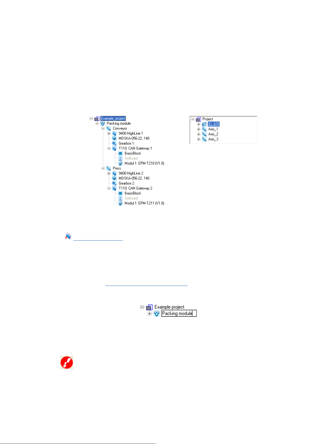
Mapping the system structure in the »Engineer« project
_ _ _ _ _ _ _ _ _ _ _ _ _ _ _ _ _ _ _ _ _ _ _ _ _ _ _ _ _ _ _ _ _ _ _ _ _ _ _ _ _ _ _ _ _ _ _ _ _ _ _ _ _ _ _ _ _ _ _ _ _ _ _ _
Tip!
Name the individual system modules uniquely. Orient yourself on your real machine
structure in order to be able to clearly identify the individual project elements.
Inserting components
After the system structure has been represented in the form of system modules and axes, the
suitable components (inverters, motors, I/O systems, gearboxes, etc.) must be inserted:
Example 1: Two 9400 HighLine drive controllers Example 2: EL 870 controller
[5-1] Examples of projects with different components
Inserting components ( 51)
Tip!
For documentation purposes, every element in the Project view can be provided with notes
and file attachments (images, circuit diagrams, CAD data, etc.).
Documentation referring to the whole system can be attached to the Project root, for
instance.
If you select an element in the Project view and press the <F2> function key, you can change
the name of the element:
•Press the <Input key> to accept the change, or the <ESC> key to discard the change.
Ambiguous designation
If the name of a component already exists in a project, it will be symbolised by the following icon:
Documentation - Add project details ( 71)
.
• By specifying the Current designation and the Designations already assigned you can define a
New designation in order to be able to clearly identify the corresponding component in the
project.
46 Lenze · Engineer · 2.13 EN - 10/2014
Page 47

Mapping the system structure in the »Engineer« project
Modularising with system modules and axes
_ _ _ _ _ _ _ _ _ _ _ _ _ _ _ _ _ _ _ _ _ _ _ _ _ _ _ _ _ _ _ _ _ _ _ _ _ _ _ _ _ _ _ _ _ _ _ _ _ _ _ _ _ _ _ _ _ _ _ _ _ _ _ _
Next steps
Have all components of the real machine structure been inserted into the project
structure?
• Now the system structure can be extended by the networks available in the
system by using the network representation.
Network
Inserting & configuring a network
5.1 Modularising with system modules and axes
In the Project tree, you can structure certain elements of a machine by means of a System module
or an Axis.
• A system module includes the implementation of a specific function (e.g. winding, positioning,
pressing) within the entire system.
( 202)
Form of modularisation Description
System module A system module ...
Axis An axis ...
5.1.1 Inserting system modules
You can insert system modules to represent a clearly arranged system structure with multiple
levels:
• ... can include devices, communication networks, applications and
documentation.
• ... can include other system modules and one or more axes.
• ... represents a defined variant of a system module and generally includes
at least one controller and one motor.
• ... can include other devices such as gearboxes in addition.
How to insert a system module:
1. In the Project view, either select ...
• ... the project element
• ... the desired system module another system module is to be inserted into.
2. Click the icon.
Lenze · Engineer · 2.13 EN - 10/2014 47
, or
Page 48

Mapping the system structure in the »Engineer« project
Modularising with system modules and axes
_ _ _ _ _ _ _ _ _ _ _ _ _ _ _ _ _ _ _ _ _ _ _ _ _ _ _ _ _ _ _ _ _ _ _ _ _ _ _ _ _ _ _ _ _ _ _ _ _ _ _ _ _ _ _ _ _ _ _ _ _ _ _ _
•Enter the Description of the system module.
• Enter an optional Comment for the axis which helps identifying the axis during later
edition.
3. Click the OK button to insert the system module into the selected element.
Components, properties & documentation
If a system module is selected in the Project view, the Workspace contains the Components,
Properties and Documentation tabs.
Tab Contents
Components All components of the system module
Data logger Data logger
Product features General information about the system module (e.g. version and person in
Documentation Optionally, notes regarding the device module and file attachments can be
5.1.2 Inserting an axis
In order to represent hierarchical system structures, you can insert one or more axes into the project
element or into a lower-level system module to achieve a clearly arranged project structure.
• An axis ...
• ... represents a specific variant of a system module.
• ... includes at least one controller and one motor and, depending on the application, can
include other devices such as gearboxes and encoders in addition.
Tip!
If you have inserted an axis, you can also select the further components of the axis (drive
controller, motor, gearbox, etc.). This saves you from having to call the Add component
function again.
( 111)
charge)
added. Documentation - Add project details
( 71)
48
How to insert an axis:
1. Open the Project view and select the system module into which the axis is to be inserted.
• An axis can directly be inserted into the project element.
Lenze · Engineer · 2.13 EN - 10/2014
Page 49

Mapping the system structure in the »Engineer« project
Modularising with system modules and axes
_ _ _ _ _ _ _ _ _ _ _ _ _ _ _ _ _ _ _ _ _ _ _ _ _ _ _ _ _ _ _ _ _ _ _ _ _ _ _ _ _ _ _ _ _ _ _ _ _ _ _ _ _ _ _ _ _ _ _ _ _ _ _ _
2. Click the icon to open the wizard for adding an axis.
Step 1 - Properties
3. Enter the Description of the axis.
• Enter an optional Comment for the axis which helps identifying the axis during later
edition.
• If the control field Insert individual components into the axis has been activated, you
must click the Next button to select the components (drive controller, motor, etc.) that
the axis is to contain.
4. Press Continue or Complete.
• Optionally, you can Insert individual components into axis or insert other components
later on.
Lenze · Engineer · 2.13 EN - 10/2014 49
Page 50

Mapping the system structure in the »Engineer« project
Modularising with system modules and axes
_ _ _ _ _ _ _ _ _ _ _ _ _ _ _ _ _ _ _ _ _ _ _ _ _ _ _ _ _ _ _ _ _ _ _ _ _ _ _ _ _ _ _ _ _ _ _ _ _ _ _ _ _ _ _ _ _ _ _ _ _ _ _ _
Step 2 - Components
5. Select the components to be contained in the axis.
6. Click the Next button.
• In the following steps, you can select the desired components for the axis.
If an axis has been selected in the Project tree, the Workspace contains the Components, Properties
and Documentation tabs.
Tab Contents
Components All components of the axis
Data logger Data logger
Product features General information about the axis (e.g. version and person in charge)
Documentation Optionally, notes regarding the device module and file attachments can be
•Click Complete to insert the axis with the selected components into the highlighted
project element.
Components, properties & documentation
( 111)
added. Documentation - Add project details ( 71)
50
Lenze · Engineer · 2.13 EN - 10/2014
Page 51

Mapping the system structure in the »Engineer« project
Inserting components
_ _ _ _ _ _ _ _ _ _ _ _ _ _ _ _ _ _ _ _ _ _ _ _ _ _ _ _ _ _ _ _ _ _ _ _ _ _ _ _ _ _ _ _ _ _ _ _ _ _ _ _ _ _ _ _ _ _ _ _ _ _ _ _
5.2 Inserting components
Tip!
Divide the real machine structure into functional subsystems which are structured by
means of system modules and axes in the »Engineer«.
Then, insert the desired components inside the system modules/axes into the project
structure.
Component Example Icon Description
Controller
Motors
Inserting controllers ( 53)
Inserting a motor ( 58)
I/O system
Power supply module Inserting a power supply module
Remote maintenance
Applications & device modules
When entering a controller, insert the respective application as well. Inserting application
( 55)
Inserting an I/O system ( 60)
( 63)
Inserting the remote maintenance
( 66)
Optionally, device modules can be inserted into the device. Inserting device modules ( 57)
Tip!
When inserting an axis, you can select the components of the axis if you ...
• ... activate the Select individual components of axis control field in a first step and
• ... then select the corresponding components.Inserting an axis
Lenze · Engineer · 2.13 EN - 10/2014 51
( 48)
Page 52

Mapping the system structure in the »Engineer« project
Inserting components
_ _ _ _ _ _ _ _ _ _ _ _ _ _ _ _ _ _ _ _ _ _ _ _ _ _ _ _ _ _ _ _ _ _ _ _ _ _ _ _ _ _ _ _ _ _ _ _ _ _ _ _ _ _ _ _ _ _ _ _ _ _ _ _
The Show latest version only option restricts the display of the search results to the most
up-to-date versions of the respective device series.
Tabs of the different components
If a component has been selected in the Project tree, the Workspace contains various tabs.
Tab Contents
Product features Name and identification of the component
All parameters Parameters of the component selected in the Project tree
Documentation Optionally, notes regarding the device module and file attachments can be
Inserting gearboxes / Inserting components
Gearboxes Inserting a gearbox
added. Documentation - Add project details
Icon Description
( 67)
( 71)
Components ...
• ... recognised online
• ... from a referential project
Inserting a device detected online
Insert from referential project
( 70)
( 67)
52
Lenze · Engineer · 2.13 EN - 10/2014
Page 53

Mapping the system structure in the »Engineer« project
Inserting components
_ _ _ _ _ _ _ _ _ _ _ _ _ _ _ _ _ _ _ _ _ _ _ _ _ _ _ _ _ _ _ _ _ _ _ _ _ _ _ _ _ _ _ _ _ _ _ _ _ _ _ _ _ _ _ _ _ _ _ _ _ _ _ _
5.2.1 Inserting controllers
How to insert a drive controller:
1. Open the Project view and select the desired system module / axis the drive
controller is to be inserted into.
2. In the Toolbar, click to open the insertion wizard.
Step 1 - component/device series (example: 9400 HighLine)
3. Select the Controller tab.
•The Search results list field shows the controllers which can be used together with the
»Engineer«:
• Optionally, you can define Search criteria for restricting the Search results.
•Click the Search button to update the search results.
4. Select the controller to be inserted in the Search results list field.
5. Click the Next button.
Step 2 - Device modules (example: 9400 HighLine)
Select the device modules plugged in the device.
Lenze · Engineer · 2.13 EN - 10/2014 53
Page 54

Mapping the system structure in the »Engineer« project
Inserting components
_ _ _ _ _ _ _ _ _ _ _ _ _ _ _ _ _ _ _ _ _ _ _ _ _ _ _ _ _ _ _ _ _ _ _ _ _ _ _ _ _ _ _ _ _ _ _ _ _ _ _ _ _ _ _ _ _ _ _ _ _ _ _ _
• Select/Delete desired device modules.
6. Click the Next button.
7. Step 3 - application
Select the application of the automation solution you want to implement.
8. Click the Next / Complete button to insert the controller.
• If no other components have been selected, the controller will be inserted into the
Inserting application
selected axis / system module without
( 55)
any other components.
54
Lenze · Engineer · 2.13 EN - 10/2014
Page 55

Mapping the system structure in the »Engineer« project
Inserting components
_ _ _ _ _ _ _ _ _ _ _ _ _ _ _ _ _ _ _ _ _ _ _ _ _ _ _ _ _ _ _ _ _ _ _ _ _ _ _ _ _ _ _ _ _ _ _ _ _ _ _ _ _ _ _ _ _ _ _ _ _ _ _ _
5.2.2 Inserting application
While inserting a controller as component, you can directly select the application. An application
can be subsequently inserted to the controller via right-click: InsertApplication
Example: Inverter Drive 8400
Category/icon Contents
Inside the device Displays the integrated technology application.
The following categories are available after you have exported an application package from the »Engineer« and
imported it into the »EASY Package Manager«: Export applications to a Lenze package (LPK file)
Packages Applications available in the »EASY Package Manager« as Lenze packages.
• Applications Displays the previously applications exported from the »Engineer« and
imported to the »EASY Package Manager« which have been created by
Lenze.
• User applications Displays the user-defined applications which have been exported from the
»Engineer« and imported to the »EASY Package Manager« .
( 267)
Lenze · Engineer · 2.13 EN - 10/2014 55
Page 56

Mapping the system structure in the »Engineer« project
Inserting components
_ _ _ _ _ _ _ _ _ _ _ _ _ _ _ _ _ _ _ _ _ _ _ _ _ _ _ _ _ _ _ _ _ _ _ _ _ _ _ _ _ _ _ _ _ _ _ _ _ _ _ _ _ _ _ _ _ _ _ _ _ _ _ _
Example: Servo Drives 9400
Tip!
Activate the Show latest version only option to only display the most up-to-date versions
of the respective applications.
Note!
If you select No application, a so-called "empty" application is assigned to the drive
controller, which you can replace with another application any time.
56
Lenze · Engineer · 2.13 EN - 10/2014
Page 57

Mapping the system structure in the »Engineer« project
Inserting components
_ _ _ _ _ _ _ _ _ _ _ _ _ _ _ _ _ _ _ _ _ _ _ _ _ _ _ _ _ _ _ _ _ _ _ _ _ _ _ _ _ _ _ _ _ _ _ _ _ _ _ _ _ _ _ _ _ _ _ _ _ _ _ _
5.2.3 Inserting device modules
Optional device modules (such as memory modules, safety modules, function modules and/or
communication modules) can be inserted into the controller when a project is created or any time
later on.
Tip!
• The steps described in the following instructions must be carried out to replace the
device module assigned to a device by another device module.
•The Show latest version only option restricts the display of the search results to the
most up-to-date versions of the respective device modules.
How to insert device modules into a device:
1. In the Project tree, select the device the device modules are to be inserted into.
2. In the Toolbar, click on .
• The device modules assigned to the device are visible.
• Select ... / Delete desired device modules.
3. Click the Complete button to insert the device modules into the controller.
• The inserted device modules are visible in
the Project tree below the device.
Lenze · Engineer · 2.13 EN - 10/2014 57
Page 58

Mapping the system structure in the »Engineer« project
Inserting components
_ _ _ _ _ _ _ _ _ _ _ _ _ _ _ _ _ _ _ _ _ _ _ _ _ _ _ _ _ _ _ _ _ _ _ _ _ _ _ _ _ _ _ _ _ _ _ _ _ _ _ _ _ _ _ _ _ _ _ _ _ _ _ _
Memory module manager, properties & documentation
If a device module has been selected in the Project tree, the Workspace contains the Properties,
Memory module manager and Documentation tabs.
Tab Contents
Memory module manager All parameters of the memory module
Product features Name and identification of the memory module
Documentation Optionally, notes regarding the device module and file attachments can be
5.2.4 Inserting controllers
This function is available up to »Engineer« HighLevel V2.17!
From »Engineer« version V2.18 on, the industrial PCs (Controllers) of the Lenze automation system
"PC-based Automation" cannot be used anymore as components. Existing »Engineer« projects
which contain Controllers as components can continued to be used.
added. Documentation - Add project details
( 71)
5.2.5 Inserting a motor
Tip!
When inserting an axis, you can also select a motor and other components if you ...
You can insert Lenze motors or user motors. For this purpose, a catalogue of user motors must be
available. Information on how to create and use user motors is provided in the following chapter:
User motors
... activate the Select individual components of axis control field in a first step and
... then select the corresponding components.Inserting an axis
How to insert a motor:
1. Open the Project tree and select the desired system module or axis the motor is to
be inserted into.
2. In the Toolbar, click to open the insertion wizard.
Step 1 - Component
3. Select the Motors tab.
( 48)
( 293)
58
Lenze · Engineer · 2.13 EN - 10/2014
Page 59

Mapping the system structure in the »Engineer« project
Inserting components
_ _ _ _ _ _ _ _ _ _ _ _ _ _ _ _ _ _ _ _ _ _ _ _ _ _ _ _ _ _ _ _ _ _ _ _ _ _ _ _ _ _ _ _ _ _ _ _ _ _ _ _ _ _ _ _ _ _ _ _ _ _ _ _
•The Search results list field displays all available motors.
• Select Lenze motors or user motors from the Selection list field.
• Optionally, you can define Search criteria for restricting the Search results.
•Click the Search button to update the search results.
4. Select the motor to be inserted in the Search results list field.
5. Click the Complete button to insert the motor.
Motor parameters, properties & documentation
If a motor has been selected in the Project tree, the Workspace contains the Motor parameters,
Properties and Documentation tabs.
Tab Contents
Motor parameters All parameters of the motor and the respective controller
Product features Name and identification of the motor
Documentation Optionally, notes regarding the device module and file attachments can be
added. Documentation - Add project details
( 71)
Lenze · Engineer · 2.13 EN - 10/2014 59
Page 60

Mapping the system structure in the »Engineer« project
Inserting components
_ _ _ _ _ _ _ _ _ _ _ _ _ _ _ _ _ _ _ _ _ _ _ _ _ _ _ _ _ _ _ _ _ _ _ _ _ _ _ _ _ _ _ _ _ _ _ _ _ _ _ _ _ _ _ _ _ _ _ _ _ _ _ _
5.2.6 Inserting an I/O system
In the »Engineer«, the I/O system 1000 and compact as well as modular IP20 systems are available.
• Modular I/O systems offer the advantage of a flexible modular structure where individual
modules can be relocated.
Detailed information on the "I/O system IP20" can be found in the "I/O system IP20
(SHB)" system manual.
Detailed information on the "I/O system 1000" can be found in the
"I/O system 1000 system manual (SHB) - Modular I/O system"
How to add an I/O system:
1. In the Toolbar, click to open the insertion wizard.
Step 1 - Component
2. Select the I/O system tab.
•The Search results list field displays all available I/O systems.
• Optionally, you can define Search criteria for restricting the Search results.
•Click the Search button to update the search results.
3. Select the I/O system to be inserted in the Search results list field.
4. Click the Next button.
5. Carry out the further instructions as described in the subchapter for the corresponding I/O
system:
Compact I/O system IP20
Modular I/O system IP20 ( 61)
( 61)
60
Lenze · Engineer · 2.13 EN - 10/2014
Page 61

Mapping the system structure in the »Engineer« project
Inserting components
_ _ _ _ _ _ _ _ _ _ _ _ _ _ _ _ _ _ _ _ _ _ _ _ _ _ _ _ _ _ _ _ _ _ _ _ _ _ _ _ _ _ _ _ _ _ _ _ _ _ _ _ _ _ _ _ _ _ _ _ _ _ _ _
5.2.6.1 System 1000
Further information on Parameter setting & configuration of the
L-force I/O system 1000 can be found in the I/O system 1000 software manual
5.2.6.2 Compact I/O system IP20
A compact I/O system has a fixed number of digital inputs and outputs.
How to add a compact I/O system:
1. Carry out steps 1 ... 5 as described in the instructions in the chapter entitled "Inserting an I/
O system ( 60) ".
2. Click the Complete button to insert the I/O system.
5.2.6.3 Modular I/O system IP20
[5-1] Example of a modular I/O system IP20
Note!
At least one module must be inserted at the CAN gateway base station.
How to add a modular I/O system:
1. Carry out steps 1 ... 5 as described in the instructions in the chapter entitled "Inserting an I/
O system ( 60) ".
2. Select a modular I/O system (CAN Gateway) and click the Next button.
3. Attach module / Insert module in question.
4. Click the Complete button to insert the I/O modules.
Lenze · Engineer · 2.13 EN - 10/2014 61
Page 62
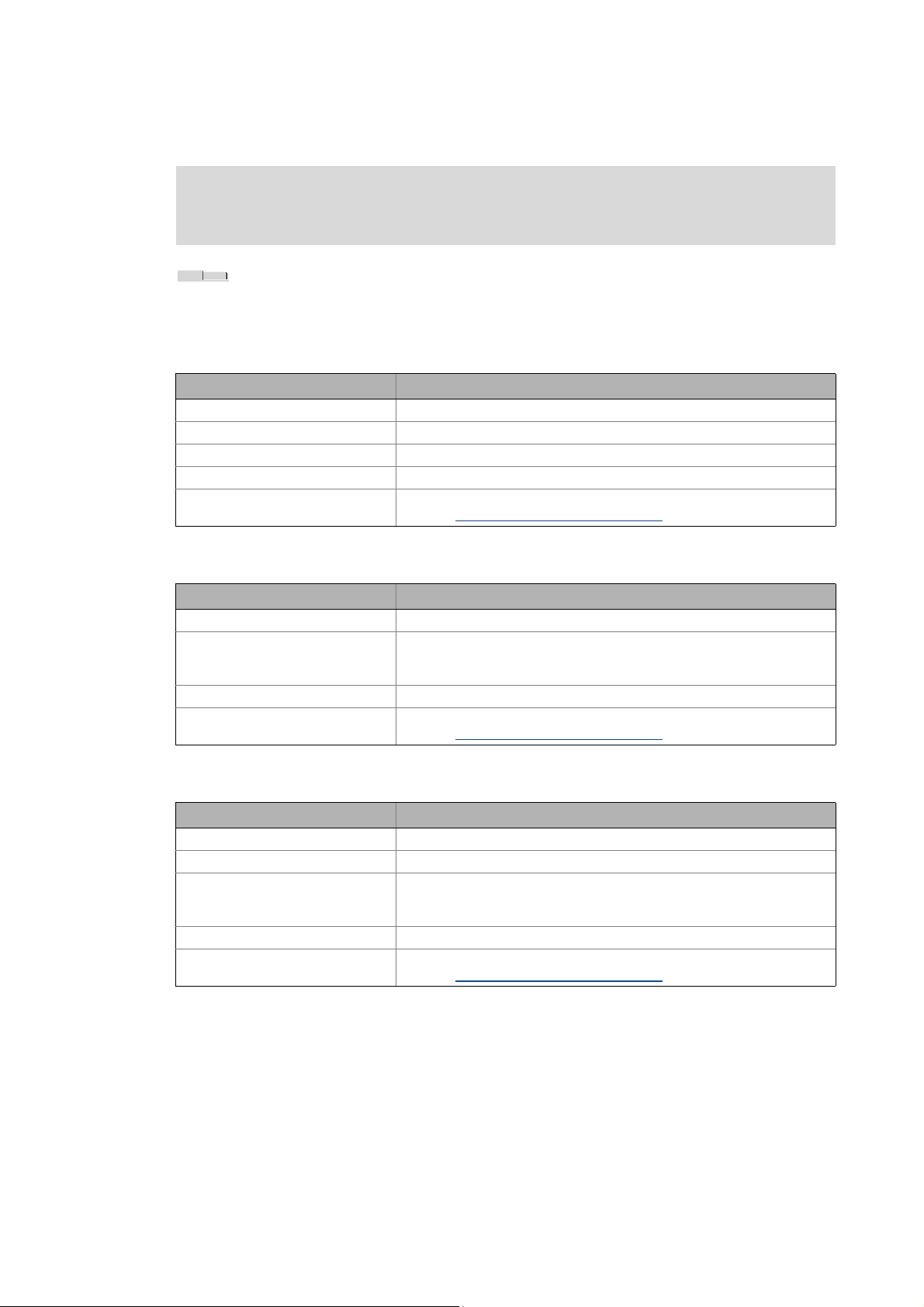
Mapping the system structure in the »Engineer« project
Inserting components
_ _ _ _ _ _ _ _ _ _ _ _ _ _ _ _ _ _ _ _ _ _ _ _ _ _ _ _ _ _ _ _ _ _ _ _ _ _ _ _ _ _ _ _ _ _ _ _ _ _ _ _ _ _ _ _ _ _ _ _ _ _ _ _
Note!
Depending on the inserted I/O module, different tabs are available!
Tabs of the I/O systems
If you select an I/O module in the Project tree, the Workspace contains different tabs.
CAN gateway
Tab Contents
Configuration Represents the I/O system.
Ports Represents the input and output ports of the CAN gateway.
All parameters Parameters (codes) of the I/O system.
Product features Project / catalogue information about the I/O system.
Documentation Optionally, notes regarding the device module and file attachments can be
added. Documentation - Add project details
( 71)
CAN gateway module
Tab Contents
Status Status of the inputs / outputs.
Parameter Parameters (codes) of the I/O system.
Product features Project / catalogue information about the I/O system.
Documentation Optionally, notes regarding the device module and file attachments can be
• The parameters of the digital modules, for instance, define how the
control signals must be transmitted (original / inverted polarity).
added. Documentation - Add project details
( 71)
Compact modules
Tab Function
Configuration Represents the I/O system.
Ports Represents the input / output ports of the I/O module.
All parameters Parameters (codes) of the I/O system.
• The parameters of the digital modules, for instance, define how the
control signals must be transmitted (original / inverted polarity).
Product features Project / catalogue information about the I/O system.
Documentation Optionally, notes regarding the device module and file attachments can be
added. Documentation - Add project details
( 71)
62
Lenze · Engineer · 2.13 EN - 10/2014
Page 63

Mapping the system structure in the »Engineer« project
Inserting components
_ _ _ _ _ _ _ _ _ _ _ _ _ _ _ _ _ _ _ _ _ _ _ _ _ _ _ _ _ _ _ _ _ _ _ _ _ _ _ _ _ _ _ _ _ _ _ _ _ _ _ _ _ _ _ _ _ _ _ _ _ _ _ _
5.2.7 Inserting a power supply module
How to insert a power supply module:
1. Open the Project view and select the desired system module / axis the power supply
module is to be inserted into.
2. In the Toolbar, click to open the insertion wizard.
Step 1 - Component
3. Select the Power supply modules tab.
•The Search results list field displays all available power supply modules.
• Optionally, you can define Search criteria for restricting the Search results.
•Click the Search button to update the search results.
4. Select the power supply module to be inserted in the Search results list field.
5. Click the Next button.
Lenze · Engineer · 2.13 EN - 10/2014 63
Page 64

Mapping the system structure in the »Engineer« project
Inserting components
_ _ _ _ _ _ _ _ _ _ _ _ _ _ _ _ _ _ _ _ _ _ _ _ _ _ _ _ _ _ _ _ _ _ _ _ _ _ _ _ _ _ _ _ _ _ _ _ _ _ _ _ _ _ _ _ _ _ _ _ _ _ _ _
Step 2 - Device modules
• Depending on the selected power supply module, various modules can be inserted into
the Device modules dialog box.
• The device modules assigned to the device are visible.
• Select ... / Delete desired device modules.
6. Click the Next / Complete button to insert the device modules.
7. Step 3 - Other components
Select other components that are to be inserted into the power supply module.
8. Click the Next button.
• The applications for the power supply module selected are displayed.
• If no specific device application has been selected for the device in this step, the
controller will be assigned an "empty" application. The application can be replaced by
another device application later on. Inserting application
( 55)
64
Lenze · Engineer · 2.13 EN - 10/2014
Page 65

Mapping the system structure in the »Engineer« project
Inserting components
_ _ _ _ _ _ _ _ _ _ _ _ _ _ _ _ _ _ _ _ _ _ _ _ _ _ _ _ _ _ _ _ _ _ _ _ _ _ _ _ _ _ _ _ _ _ _ _ _ _ _ _ _ _ _ _ _ _ _ _ _ _ _ _
• Select the desired application.
•Click the Complete button to insert the power supply module.
Lenze · Engineer · 2.13 EN - 10/2014 65
Page 66

Mapping the system structure in the »Engineer« project
Inserting components
_ _ _ _ _ _ _ _ _ _ _ _ _ _ _ _ _ _ _ _ _ _ _ _ _ _ _ _ _ _ _ _ _ _ _ _ _ _ _ _ _ _ _ _ _ _ _ _ _ _ _ _ _ _ _ _ _ _ _ _ _ _ _ _
5.2.8 Inserting the remote maintenance
How to insert a remote maintenance module:
1. Open the Project tree and select the desired system module / axis the power supply
module is to be inserted into.
2. In the Toolbar, click to open the insertion wizard.
Step 1 - Component
3. Select the Remote maintenance tab.
•The Search results list field displays the available Remote maintenance modules.
4. Select the desired remote maintenance module.
5. Press Complete.
66
Lenze · Engineer · 2.13 EN - 10/2014
Page 67

Mapping the system structure in the »Engineer« project
Inserting a gearbox
_ _ _ _ _ _ _ _ _ _ _ _ _ _ _ _ _ _ _ _ _ _ _ _ _ _ _ _ _ _ _ _ _ _ _ _ _ _ _ _ _ _ _ _ _ _ _ _ _ _ _ _ _ _ _ _ _ _ _ _ _ _ _ _
5.3 Inserting a gearbox
Tip!
The gearbox and other components can be selected when inserting an axis by activating
the Select individual components of axis option in a first step. Inserting an axis
( 48)
How to add a gearbox:
1. Open the Project view and select the desired system module / axis the gearbox is to
be inserted into.
2. In the Toolbar, click on .
3. Enter the Description of the gearbox.
4. Enter the Teeth number (numerator) and Teeth number (denominator) of the gearbox to
have the resulting gearbox factor calculated.
5. Click the OK button to insert the gearbox into the selected project element.
Gearbox parameters, properties & documentation
If you select an inserted gearbox in the Project view, the workspace contains the Gearbox
parameters, Properties and Documentation tabs.
Tab Contents
Gearbox factor Settings for the ratio and the moment of inertia of the gearbox.
Product features Name and identification of the gearbox.
Documentation Optionally, notes regarding the device module and file attachments can be
added. Documentation - Add project details
5.4 Inserting a device detected online
( 71)
If the machine structure includes multiple controllers which are not contained in the Project tree,
they can be inserted into the project via online recognition.
Lenze · Engineer · 2.13 EN - 10/2014 67
Page 68

Mapping the system structure in the »Engineer« project
Inserting a device detected online
_ _ _ _ _ _ _ _ _ _ _ _ _ _ _ _ _ _ _ _ _ _ _ _ _ _ _ _ _ _ _ _ _ _ _ _ _ _ _ _ _ _ _ _ _ _ _ _ _ _ _ _ _ _ _ _ _ _ _ _ _ _ _ _
Note!
• For online recognition, the desired field device must ...
• ... be switched on.
• ... support online recognition.
•An unidentified device/module cannot be inserted into the project.
• The »Engineer« reads out the device configuration (firmware version and module assembly).
The »Engineer« determines the original configuration the application was created for if this
process is supported by the device.
• If there is a difference between the original and the actual configuration, you can select which
configuration is to be inserted into the project tree.
Note!
• Only the original version can be inserted if ...
• ... the version of the safe parameter set for the SM301 safety module varies:
Insertion into the project without further inquiry.
• ... a device description for the current firmware version is missing. The »Engineer«
is only provided with the version used for the original creation of the application:
The device recognised online is listed with the icon under identified devices.
How to insert the field device online into the project:
1. Select the desired position for insertion in the Project tree.
2. Select the InsertDevice detected online menu command.
68
3. Select the suitable bus connection from the Bus connection selection field.
4. Press Start Search.
• Identified devices can be inserted into the project. Information provided under must
be observed if the device description is not suitable.
Lenze · Engineer · 2.13 EN - 10/2014
Page 69

Mapping the system structure in the »Engineer« project
Inserting a device detected online
_ _ _ _ _ _ _ _ _ _ _ _ _ _ _ _ _ _ _ _ _ _ _ _ _ _ _ _ _ _ _ _ _ _ _ _ _ _ _ _ _ _ _ _ _ _ _ _ _ _ _ _ _ _ _ _ _ _ _ _ _ _ _ _
Note: The CAN bus connection only lists devices that are not yet included in the Project tree.
• Unidentified devices do not have suitable device descriptions. Unidentified devices cannot
be inserted into the project.
5. Select the desired field devices and click OK.
•Click Start to transfer the device parameters to the »Engineer« project.
•Click Close to insert the field device (without parameter download) into the »Engineer«
project.
• The field device has been inserted online into the Project tree:
Lenze · Engineer · 2.13 EN - 10/2014 69
Page 70

Mapping the system structure in the »Engineer« project
Insert from referential project
_ _ _ _ _ _ _ _ _ _ _ _ _ _ _ _ _ _ _ _ _ _ _ _ _ _ _ _ _ _ _ _ _ _ _ _ _ _ _ _ _ _ _ _ _ _ _ _ _ _ _ _ _ _ _ _ _ _ _ _ _ _ _ _
5.5 Insert from referential project
With this function you can import already configured field devices from other »Engineer« projects
into a current »Engineer« project.
How to insert field devices from other projects:
1. Open the Project view and select the desired system module / axis the field device is
to be inserted into.
2. Select the menu command InsertInsert from referential project .
3. Click Search to open the desired project (*.afs format, ).
4. Select the desired field device and click Insert.
70
Lenze · Engineer · 2.13 EN - 10/2014
Page 71

Mapping the system structure in the »Engineer« project
Replace component
_ _ _ _ _ _ _ _ _ _ _ _ _ _ _ _ _ _ _ _ _ _ _ _ _ _ _ _ _ _ _ _ _ _ _ _ _ _ _ _ _ _ _ _ _ _ _ _ _ _ _ _ _ _ _ _ _ _ _ _ _ _ _ _
5.6 Replace component
Replace component enables you to replace devices of the same device series.
• It makes sense to replace a component within a project, for instance, if the device software is
updated.
Note!
The function Replace component can only be executed within the same device series!
How to replace a component:
1. Select the component to be replaced in the Project tree.
2. Select the command Replace component in the context menu.
3. Select the desired component in the Replacing a component dialog box.
• If no more recent software version of the corresponding component is available, no
components can be selected.
4. After clicking OK the component is inserted in the project and replaces the previous
component.
5.7 Documentation - Add project details
Every Project element can be added notes and file attachments via the Documentation tab.
• That way, detailed documentation for every project element is possible.
• Using detailed documentation, the element or the whole system can be documented and
important information on the project can be made available to other people working on the
project, e.g:
• Sketches & photographs of the system,
• Processing tasks,
• Work instructions,
• Circuit diagrams,
•CAD data,
• Lists of parts, etc.
Lenze · Engineer · 2.13 EN - 10/2014 71
Page 72

Mapping the system structure in the »Engineer« project
Documentation - Add project details
_ _ _ _ _ _ _ _ _ _ _ _ _ _ _ _ _ _ _ _ _ _ _ _ _ _ _ _ _ _ _ _ _ _ _ _ _ _ _ _ _ _ _ _ _ _ _ _ _ _ _ _ _ _ _ _ _ _ _ _ _ _ _ _
The Documentation list shows
documents available for the
project element.
On the right-hand side the
properties of the element
selected from the
Documentation list are shown.
If you select the Preview from
the View list field, on the right a
preview of the element
selected from the
Documentation list is shown
instead.
Tip!
The Preview shows all types of documents the Microsoft® Internet Explorer is able to
display, e.g. HTML and ASCII files, graphics in the JPEG or GIF format, or PDF files..
The document types which can be shown in detail depend on the display plug-ins installed
for the Microsoft® Internet Explorer.
72
Lenze · Engineer · 2.13 EN - 10/2014
Page 73

Mapping the system structure in the »Engineer« project
Documentation - Add project details
_ _ _ _ _ _ _ _ _ _ _ _ _ _ _ _ _ _ _ _ _ _ _ _ _ _ _ _ _ _ _ _ _ _ _ _ _ _ _ _ _ _ _ _ _ _ _ _ _ _ _ _ _ _ _ _ _ _ _ _ _ _ _ _
Editing the documentation list
Icon Function
Insert note
Copy file into the project
• After you have selected the corresponding file within your desktop environment, a copy of this
file is stored in the project folder.
Add a linkage to a file
• After you have selected the corresponding file within your desktop environment, a link to this
document is stored in the project folder.
Open document
• By means of this function you can open a selected document from the documentation list.
Save document selected
• By means of this function you can save a copy of the selected document from the project folder
to a selectable folder within your desktop environment.
Delete element selected from the documentation list
Display area
Above the display area, the View list field shows the selection preview and the file characteristics:
Command Function
Preview Showing properties relating to the element selected in the documentation list
File properties Showing a preview of the selected document or text of the selected note
Lenze · Engineer · 2.13 EN - 10/2014 73
Page 74

Mapping the system structure in the »Engineer« project
Protecting safe parameters - project-related password entry
_ _ _ _ _ _ _ _ _ _ _ _ _ _ _ _ _ _ _ _ _ _ _ _ _ _ _ _ _ _ _ _ _ _ _ _ _ _ _ _ _ _ _ _ _ _ _ _ _ _ _ _ _ _ _ _ _ _ _ _ _ _ _ _
5.8 Protecting safe parameters - project-related password entry
This function is available from »Engineer« HighLevel V2.14!
The »Engineer« provides a password protection which serves to protect the parameter setting of the
higher-order safety functions from alterations in the project for the device series 8400 and 9400.
The password...
• ... can be set on the Protection tab if the project root has been selected in the project tree.
• ...is only valid inside the project (no transmission to the controller or safety module). If a
password is stored in the project and this project is used, the safe parameters can only be edited
after the password has been entered.
How to activate the protection of the save parameters:
1. Select the project root in the project tree.
2. Assign the desired password on the Protection tab.
• After the password has been set, the safe parameters (tab Safe configuration, safe
parameters) of all included devices can only be edited inside the project after the
corresponding password has been entered.
74
Lenze · Engineer · 2.13 EN - 10/2014
Page 75

Establishing an online connection
_ _ _ _ _ _ _ _ _ _ _ _ _ _ _ _ _ _ _ _ _ _ _ _ _ _ _ _ _ _ _ _ _ _ _ _ _ _ _ _ _ _ _ _ _ _ _ _ _ _ _ _ _ _ _ _ _ _ _ _ _ _ _ _
6 Establishing an online connection
In this chapter you will learn about how you can establish an online connection with the »Engineer«
and how you can close this online connection again.
An online connection is required to e.g. make parameter settings in the device or for diagnosing the
device. The »Engineer« can have online connections to multiple devices at the same time.
To establish an online connection, the desired device / devices must
• ... be inserted into the Project tree and
• ... be connected to the Engineering PC via suitable communication accessories (e.g. diagnostic
adapters, system bus adapters or Ethernet).
Stop!
If you change parameters in the »Engineer« while the controller is connected online, the
changes will be directly accepted by the controller!
Detailed information about the respective bus system can be found in the corresponding
communication manual
• The functions for establishing/closing an online connection can be executed via the Toolbar or
the Online menu:
Icon Menu command Shortcut
Going online
Setting the communication path
Bus connection
• Diagnostic adapter
• CAN
• Ethernet / Ethernet IPC
• PROFIBUS
• PROFINET
• Gateway controller -> CAN
• Gateway controller -> EtherCAT
• Gateway Controller -> EtherCAT ADS (Beckhoff)
• Gateway Siemens - STEP 7 Communication Server (available by call in STEP 7)
( 89)
Going offline
( 77) <F4>
( 79)
( 80)
( 81)
( 83)
( 84)
( 85)
( 85)
( 86)
( 87)
( 96) <Shift>+<F4>
Lenze · Engineer · 2.13 EN - 10/2014 75
Page 76

Establishing an online connection
Build project
_ _ _ _ _ _ _ _ _ _ _ _ _ _ _ _ _ _ _ _ _ _ _ _ _ _ _ _ _ _ _ _ _ _ _ _ _ _ _ _ _ _ _ _ _ _ _ _ _ _ _ _ _ _ _ _ _ _ _ _ _ _ _ _
Tip!
In the »Engineer« an existing online connection can be identified by the animated graphics
below the Project view bar:
6.1 Build project
In order to render changes on a project effective, the project must be updated manually. Each device
inserted in the »Engineer« has a separate update status. Like this the update is only required for the
device changed in each case (and not for the whole project).
How to update the project:
1. In the Toolbar, activate .
• Confirm the note to open the Build project dialog box.
Tip: The dialog box can be opened via the button in the Toolbar, the Tools Build
project menu command, or the <F11> key.
76
•Activate the Rebuild all option to update all project elements. The update process can
take longer in case of bigger projects.
2. Click the Build button.
• When the update is completed, a note appears whether the update was successful.
Lenze · Engineer · 2.13 EN - 10/2014
Page 77

Establishing an online connection
Going online
_ _ _ _ _ _ _ _ _ _ _ _ _ _ _ _ _ _ _ _ _ _ _ _ _ _ _ _ _ _ _ _ _ _ _ _ _ _ _ _ _ _ _ _ _ _ _ _ _ _ _ _ _ _ _ _ _ _ _ _ _ _ _ _
3. Confirm the note with OK.
• When the update has been executed successfully, the Build project dialog box is closed
and the Go online process is continued.
• If an error has occurred during the update, the Build project dialog box remains open. In
this case, please observe the messages in the "Build" window. Click Close to close the
dialog box and cancel the Go online process.
6.2 Going online
Stop!
If you change parameters in the »Engineer« while the controller is connected online, the
changes will be directly accepted by the controller!
Going online with a changed project
When the Go online command is executed, the »Engineer« checks whether the current project
settings have been transferred to the devices. If one or several devices have the "changed" status, a
note asks you to update the project.
• Confirm the query in order to update the project. This serves to transfer the changes to the
device. Build project
( 76)
How to go online to a device:
1. Select the device with which the online connection is to be established in the Project view
of the :
Example 1: 9400 HighLine controller Example 2: EL 870 controller and three axes
Tip: You can establish an online connection to all or multiple devices by selecting the
project root or a system module in the Project view. Then select the devices included in the
selected element for the online connection in the Communication path dialog box.
2. Click on the icon o r select th e Online Go online menu command (keyboard command
<F4>).
If the changes made in the project have not been accepted yet, update the project.Build
project ( 76)
If an update is to be carried out:
•Click Yes to open the Build project dialog box.
•Click Build in the Build project dialog box to update the changed project elements.
• When the update is completed, a note appears whether the update was successful.
If a communication path has not yet been set for the device, the Communication path
Lenze · Engineer · 2.13 EN - 10/2014 77
Page 78

Establishing an online connection
Going online
_ _ _ _ _ _ _ _ _ _ _ _ _ _ _ _ _ _ _ _ _ _ _ _ _ _ _ _ _ _ _ _ _ _ _ _ _ _ _ _ _ _ _ _ _ _ _ _ _ _ _ _ _ _ _ _ _ _ _ _ _ _ _ _
dialog box appears after the update has been carried out:
• Detailed information on how to set the communication path can be found in the
following subchapter "Setting the communication path
After the communication path to be used has been set correctly:
3. Click Connect.
• The dialog box closes and the online connection to the device is established.
• The available online connection to the device is displayed by a yellow highlighted icon in
the Project view:
". ( 79)
Example 1: 9400 HighLine controller
Now you can use the icons and to easily build up and close an online connection
with the device. The communication settings are only required when communication with
a device is built up for the first time.
• If you want to change the communication path configured, select the Online Set
communication path and go online menu command.
• The desired changes for all devices of the project are to be carried out in the
Communication path dialog box.
• When an online connection has been established the current parameter settings in the device
are displayed in the »Engineer«
• The yellow background colour signalises an online connection and the online
parameters of a device.Displaying parameter values
Example 2: EL 870 controller and four axes
( 22)
78
Lenze · Engineer · 2.13 EN - 10/2014
Page 79

Establishing an online connection
Going online
_ _ _ _ _ _ _ _ _ _ _ _ _ _ _ _ _ _ _ _ _ _ _ _ _ _ _ _ _ _ _ _ _ _ _ _ _ _ _ _ _ _ _ _ _ _ _ _ _ _ _ _ _ _ _ _ _ _ _ _ _ _ _ _
6.2.1 Setting the communication path
Note!
For "going online" the communication settings are only required when the first
connection to the device is established. When the Go online command is executed again,
the Communication path dialog box is no longer shown and the online connection via
the bus connection set is established immediately.
To open the Communication path again, select the OnlineSet communication path and
go online menu command. Like this you can alter a communication path that has already
been set.
In the Communication path dialog box, the selected device is shown in the upper list field together
with the currently selected bus connection.
• If, instead of a device, the uppermost project element or a system module has been selected in
the Project view, all the devices contained in the element selected are displayed:
[6-1] Example: Communication path with a 9400 HighLine controller and a controller
• If you select a device from the upper list field, you can set or alter the communication settings
for this device in the lower dialog area.
• The bus connection suitable for the respective device is preselected in the Bus connection list
field and can be checked with the Search/Enter button.
• The other bus connections available for a device in the Bus connection list field depend on the
respective device and its communication modules/interfaces.
• By clicking the checkmark in the Selection column you can exclude the corresponding device
from going online.
If you press Connect, the online connection is established to all devices with the checkmark in the
Selection column.
Configuring a bus connection
Detailed information on how to configure the respective bus connection can be found in the
corresponding subchapter of the desired bus connection:
Diagnostic adapter
CAN ( 81)
( 80)
Lenze · Engineer · 2.13 EN - 10/2014 79
Page 80

Establishing an online connection
Going online
_ _ _ _ _ _ _ _ _ _ _ _ _ _ _ _ _ _ _ _ _ _ _ _ _ _ _ _ _ _ _ _ _ _ _ _ _ _ _ _ _ _ _ _ _ _ _ _ _ _ _ _ _ _ _ _ _ _ _ _ _ _ _ _
Ethernet / Ethernet IPC
PROFIBUS
PROFINET
Gateway controller -> CAN ( 85)
Gateway controller -> EtherCAT
Gateway Controller -> EtherCAT ADS (Beckhoff)
Gateway Siemens - STEP 7 Communication Server (available by call in STEP 7) ( 89)
6.2.1.1 Diagnostic adapter
For commissioning and diagnostics of a controller of the Inverter Drives 8400 and Servo Drives 9400
series you can e.g. use the diagnostic adapter offered by Lenze:
( 84)
( 85)
( 83)
( 86)
( 87)
[6-2] Example of a connection via diagnostic adapter between an Engineering PC and a 9400 HighLine.
Note!
Observe the documentation supplied with the diagnostic adapter!
The online connection to the diagnostic adapter is a 1:1 connection.
Tip!
Via the menu command OnlineStatus of diagnostic adapter, you can have the operating
status of the diagnostic adapters connected to the Engineering PC displayed.
Preconditions:
• The diagnostic adapter is connected to the diagnostic interface X6 at the controller and to a free
USB port at the (Engineering) PC.
• The driver required for the diagnostic adapter is installed.
• The control electronics of the controller is supplied via the X2 plug with 24-V low voltage.
How to configure an online connection via the diagnostic adapter:
80
1. Go to the Communication path dialog box and select "Diagnostic adapter" from the Bus
connection list field.
The following step is only required if several diagnostic adapters are connected to the PC:
Lenze · Engineer · 2.13 EN - 10/2014
Page 81

Establishing an online connection
Going online
_ _ _ _ _ _ _ _ _ _ _ _ _ _ _ _ _ _ _ _ _ _ _ _ _ _ _ _ _ _ _ _ _ _ _ _ _ _ _ _ _ _ _ _ _ _ _ _ _ _ _ _ _ _ _ _ _ _ _ _ _ _ _ _
2. Press Search/Enter....
•The Select device access path dialog box is shown:
6.2.1.2 CAN
Certain Lenze products are provided with an integrated CAN interface.
• Among other things, process data and parameter values can be exchanged between the nodes
• The CAN interface transfers data objects in accordance with the CANopen communication
Tip!
3. Select the corresponding device from the Field devices located list field.
4. Press OK.
•The Select device access path dialog box is closed.
•In the Communication path dialog box, the Device access path column displays the
corresponding device access path (e.g. "can:/dev1/").
via the CAN interface. Furthermore, the interface allows for the connection of other
components such as peripheral terminals, operator and input devices (HMIs), as well as external
control and host systems.
profile (CiA DS301, version 4.02), which was created under the umbrella association of CiA (CAN
in Automation) to conform with the CAL (CAN Application Layer).
Detailed information about the subject "CAN" can be found in the Lenze library in the "CAN"
Communication Manual.
How to configure an online connection via CAN:
1. Go to the Communication path dialog box and select "CAN " from the Bus connection list
field.
2. Press Search/Enter....
Lenze · Engineer · 2.13 EN - 10/2014 81
Page 82

Establishing an online connection
Going online
_ _ _ _ _ _ _ _ _ _ _ _ _ _ _ _ _ _ _ _ _ _ _ _ _ _ _ _ _ _ _ _ _ _ _ _ _ _ _ _ _ _ _ _ _ _ _ _ _ _ _ _ _ _ _ _ _ _ _ _ _ _ _ _
•The Select device access path dialog box is shown:
3. Select the corresponding device from the Field devices located list field.
4. Press OK.
•The Select device access path dialog box is closed.
•In the Communication path dialog box, the Device access path column displays the
corresponding device access path (e.g. "can:/dev1/").
82
Lenze · Engineer · 2.13 EN - 10/2014
Page 83

Establishing an online connection
Going online
_ _ _ _ _ _ _ _ _ _ _ _ _ _ _ _ _ _ _ _ _ _ _ _ _ _ _ _ _ _ _ _ _ _ _ _ _ _ _ _ _ _ _ _ _ _ _ _ _ _ _ _ _ _ _ _ _ _ _ _ _ _ _ _
6.2.1.3 Ethernet / Ethernet IPC
You can establish an online connection to the device via a TCP/IP network if the device (e.g a
controller) is equipped with an Ethernet network adapter and the PC is also provided with an access
to this TCP/IP network (e.g. via a network interface card).
Note!
For the communication settings in the »Engineer« you require the IP address of the
device.
Tip!
Note down the set IP address using an adhesive label on the device.
Detailed information on the "Ethernet" can be found in the "Ethernet" communication
manual.
How to configure an online connection via Ethernet:
1. Select desired device in the Project tree.
2. Execute the OnlineSet communication path and go online menu command.
3. Go to the Communication path dialog box and select "Ethernet IPC " from the Bus
connection list field.
4. Press Search/Enter....
•The Enter IP address dialog box is displayed:
5. Enter the IP address of the device.
•By clicking the Ping ... button, you can check whether a device can be reached via the set
IP address.
Caution: This does not mean that the intended device can be reached via this IP address!
6. Press OK.
•The Device access path column displays the IP address (e.g. "IPC:192_168_5_99.DM.").
Lenze · Engineer · 2.13 EN - 10/2014 83
Page 84

Establishing an online connection
Going online
_ _ _ _ _ _ _ _ _ _ _ _ _ _ _ _ _ _ _ _ _ _ _ _ _ _ _ _ _ _ _ _ _ _ _ _ _ _ _ _ _ _ _ _ _ _ _ _ _ _ _ _ _ _ _ _ _ _ _ _ _ _ _ _
6.2.1.4 PROFIBUS
For each of the Inverter Drives 8400 and Servo Drives 9400 series of devices, there is a PROFIBUS
communication module with which you can set up an online connection to a field device via
PROFIBUS. »Engineer« uses the PROFIBUS DPV1 function as a Class 2 master.
Note!
In order to be able to set up an online connection via PROFIBUS, the following
requirements must first be met:
• Installation of the ProfilServer: The ProfilServer is available as a separate setup on the
»Engineer«installation CD.
• The Engineering PC (Windows PC on which »Engineer« has been installed) must have
a suitable PROFIBUS interface. For this purpose, a PROFIBUS card and the associated
driver software have to be installed, For more information on installation of the
PROFIBUS card, please refer to the manufacturer's documentation.
How to configure an online connection via PROFIBUS:
1. Open the Communication path dialog box in the Bus connection list field and select the
"PROFIBUS" entry.
2. Press Search/Enter....
•The Select device access path dialog box is shown:
3. Select the corresponding device from the Field devices located list field.
4. Press OK.
•The Select device access path dialog box is closed.
•In the Communication path dialog box, the Device access path column displays the
corresponding device access path (e.g. "OPC_SimaticNET_PD_1/
DP2___brd1_seg0_dev4_/1/").
84
Lenze · Engineer · 2.13 EN - 10/2014
Page 85

Establishing an online connection
Going online
_ _ _ _ _ _ _ _ _ _ _ _ _ _ _ _ _ _ _ _ _ _ _ _ _ _ _ _ _ _ _ _ _ _ _ _ _ _ _ _ _ _ _ _ _ _ _ _ _ _ _ _ _ _ _ _ _ _ _ _ _ _ _ _
6.2.1.5 PROFINET
For the Servo Drives 9400 device series a PROFINET communication module is provided,
by means of which you can establish an online connection to a field device via PROFINET.
More information on Parameter setting & configuration with PROFINET can be found in
the PROFINET communication manual , section "Establish online connection via PROFINET
using the Lenze »Engineer«"
6.2.1.6 Gateway controller -> CAN
The controller offers a gateway function to establish an online connection to a field device via CAN.
How to configure an online connection to a field device which is connected to the
controller via CAN:
1. Go to the Communication path dialog box and select the entry "Gateway controller -> CAB"
from the Bus connection list field.
2. Press Search/Enter....
•The Gateway controller -> Set up CAN system bus dialog box is shown:
3. Enter the IP address of the controller.
•By pressing Ping you can carry out a simple test on whether a device can actually be
reached via the IP address set.
Please note: However, this has not necessarily got to mean that the intended device can
be reached via this IP address!
Lenze · Engineer · 2.13 EN - 10/2014 85
Page 86

Establishing an online connection
Going online
_ _ _ _ _ _ _ _ _ _ _ _ _ _ _ _ _ _ _ _ _ _ _ _ _ _ _ _ _ _ _ _ _ _ _ _ _ _ _ _ _ _ _ _ _ _ _ _ _ _ _ _ _ _ _ _ _ _ _ _ _ _ _ _
4. Press OK.
•In the Communication path dialog box, the Device access path column displays the
corresponding device access path (e.g. "IPC:172_31_207_254.CAN.can1.dev1.").
6.2.1.7 Gateway controller -> EtherCAT
The controller offers a gateway function to establish an online connection to a field device via
EtherCAT.
How to configure an online connection to a field device which is connected to the
controller via EtherCAT:
1. Go to the Communication path dialog box and select the entry "Gateway controller ->
EtherCAT" from the Bus connection list field.
2. Press Search/Enter....
•The Gateway controller -> Set up EtherCAT bus dialog box is shown:
3. Enter the IP address of the controller.
•By pressing Ping you can carry out a simple test on whether a device can actually be
reached via the IP address set.
Please note: However, this has not necessarily got to mean that the intended device can
be reached via this IP address!
4. Press OK.
•The Enter IP address dialog box is closed.
•In the Communication path dialog box, the Device access path column displays the
corresponding device access path (e.g. "IPC:172_31_207_254.ECAT.ecat1.dev1001.").
86
Lenze · Engineer · 2.13 EN - 10/2014
Page 87

Establishing an online connection
Going online
_ _ _ _ _ _ _ _ _ _ _ _ _ _ _ _ _ _ _ _ _ _ _ _ _ _ _ _ _ _ _ _ _ _ _ _ _ _ _ _ _ _ _ _ _ _ _ _ _ _ _ _ _ _ _ _ _ _ _ _ _ _ _ _
6.2.1.8 Gateway Controller -> EtherCAT ADS (Beckhoff)
The Gateway EtherCAT ADS bus connection enables you to establish an online connection to a Lenze
controller that is connected to a Beckhoff control system via EtherCAT (gateway function).
Note!
In order to go online, the EtherCAT fieldbus must be at least in the Pre-Operational
status.
[6-3] Sample configuration for using the ADS EtherCAT bus server
How to proceed:
1. Select the project root in the project. Alternative: Creating a new project (starting the
search for devices connected) ( 34)
2. Execute the menu command InsertDevice detected online.
3. Select Gateway Controller -> EtherCAT ADS as bus connection.
4. Entering access data
• Enter the access data suitable for control via the Insert address button.
•The Search button prompts the control (Beckhoff) to display the fieldbus nodes
connected to the EtherCAT segment.
How to use the communication path EtherCAT ADS:
1. Mark the desired controller in the project tree to which a gateway connection is to be built
up via EtherCAT ADS.
2. Call the online command Online Set communication path and go online (F4).
Lenze · Engineer · 2.13 EN - 10/2014 87
Page 88

Establishing an online connection
Going online
_ _ _ _ _ _ _ _ _ _ _ _ _ _ _ _ _ _ _ _ _ _ _ _ _ _ _ _ _ _ _ _ _ _ _ _ _ _ _ _ _ _ _ _ _ _ _ _ _ _ _ _ _ _ _ _ _ _ _ _ _ _ _ _
•Select Gateway -> EtherCAT ADS as bus connection.
3. In the area enter the access data suitable for the control.
• Enter the user name, password as well as IP address and AMS-NetID of the EtherCAT
interface of the control.
4. In area , enter the EtherCAT address of the field device to which an online connection is
to be established.
• Alternatively, you can press Search/enter which calls the Select Device Access Path dialog
window. As a consequence, the »Engineer« prompts the control to display the devices
detected at the EtherCAT segment.
88
Lenze · Engineer · 2.13 EN - 10/2014
Page 89

Establishing an online connection
Going online
_ _ _ _ _ _ _ _ _ _ _ _ _ _ _ _ _ _ _ _ _ _ _ _ _ _ _ _ _ _ _ _ _ _ _ _ _ _ _ _ _ _ _ _ _ _ _ _ _ _ _ _ _ _ _ _ _ _ _ _ _ _ _ _
6.2.1.9 Gateway Siemens - STEP 7 Communication Server (available by call in STEP 7)
The »Engineer« internally provides a interface for communication purposes via TCI.
Note!
To be able to select TCI as bus connection, the »Engineer« must be called from the »STEP
7« software by Siemens.
• That way, the »Engineer« then provides the "STEP 7 Communication Server" bus
connection.
Please assure yourself that the used Siemens PLC supports the TCI function! Further
information is provided e.g. in the Siemens support database.
Standard procedure - example: PROFIBUS bus system
This section provides information about the basic steps which are required to be able to use the
"STEP 7 Communication Server" bus connection in the »Engineer«.
Components Version
Controller
Communication module
Technology application
Inverter Drives 8400 StateLine
PROFIBUS module
TA - actuating drive speed
Servo Drives 9400 HighLine
PROFIBUS module
TA - actuating drive speed
Software
• Lenze »Engineer« 2.9
• Siemens »STEP 7« 5.4 (SP4)
Firmware
03.00.00
1.0
1.0
05.00.42
1.0
03.0.3
Note!
The following description refers to the stated versions. Depending on the version,
individual steps of this description may be irrelevant, or additional steps may be
required.
How to proceed:
1. Create a new project in the »Engineer« including the desired modules, axes and
components. Getting started: creating a project
Lenze · Engineer · 2.13 EN - 10/2014 89
( 30)
Page 90

Establishing an online connection
Going online
_ _ _ _ _ _ _ _ _ _ _ _ _ _ _ _ _ _ _ _ _ _ _ _ _ _ _ _ _ _ _ _ _ _ _ _ _ _ _ _ _ _ _ _ _ _ _ _ _ _ _ _ _ _ _ _ _ _ _ _ _ _ _ _
Observe the naming of the controllers (the names of the components in question must be
identical in the »Engineer« and in »STEP 7«):
• 9400 for 9400 HighLine
• 8400 for 8400 StateLine
2. In the HW Config of »STEP 7« ...
...you create a PROFIBUS network.
... you create the desired Lenze PROFIBUS nodes and their respective node addresses.
• Example: a 94xx (address: 3) and an 84xx (address: 4) PROFIBUS:
Note: The selection of the process data configuration does not affect the TCI
communication!
90
Lenze · Engineer · 2.13 EN - 10/2014
Page 91

Establishing an online connection
Going online
_ _ _ _ _ _ _ _ _ _ _ _ _ _ _ _ _ _ _ _ _ _ _ _ _ _ _ _ _ _ _ _ _ _ _ _ _ _ _ _ _ _ _ _ _ _ _ _ _ _ _ _ _ _ _ _ _ _ _ _ _ _ _ _
Name the controller according to the naming in the »Engineer« project:
• 9400 for 9400 HighLine
• 8400 for 8400 StateLine
3. Establish an Ethernet connection to the PROFIBUS-CPU
• Load the »STEP 7« project into the CPU.
4. Integrate the PG/PC connection in the »STEP 7« project.
• If there is no PG/PC connection, an error message appears in the »Engineer« ("Insert PG/
PC station").
5. Insert PG/PC station.
• Menu command InsertStationPG/PC
6. Select interface.
• Double-click on the inserted PC/PC station to display the properties.
Lenze · Engineer · 2.13 EN - 10/2014 91
Page 92

Establishing an online connection
Going online
_ _ _ _ _ _ _ _ _ _ _ _ _ _ _ _ _ _ _ _ _ _ _ _ _ _ _ _ _ _ _ _ _ _ _ _ _ _ _ _ _ _ _ _ _ _ _ _ _ _ _ _ _ _ _ _ _ _ _ _ _ _ _ _
•On the Interfaces tab, click the New button.
7. Select the Ethernet connection to be used for the online connection.
The Ethernet connection must be the connection previously projected in the HWCONFIG.
• Example: select Ethernet connection Ethernet(1)
• Accept selection with OK.
8. The previously selected Ethernet interface must be assigned to the PG/PC connection.
92
• Assign selected PG/PC connection: click the Assign button.
• Confirm following query with OK to assign the connection.
Lenze · Engineer · 2.13 EN - 10/2014
Page 93

Establishing an online connection
Going online
_ _ _ _ _ _ _ _ _ _ _ _ _ _ _ _ _ _ _ _ _ _ _ _ _ _ _ _ _ _ _ _ _ _ _ _ _ _ _ _ _ _ _ _ _ _ _ _ _ _ _ _ _ _ _ _ _ _ _ _ _ _ _ _
The PG/PC station is active in the »STEP 7« project.
• The icon symbolises that the connection is active.
9. Transfer the TCI communication parameters in the HW Config in the context menu of the
connection by executing the Start device toolL-force Engineer command.
If the previously created »Engineer« project is open, confirm the query with Yes.
Alternatively, the »Engineer« is started and the corresponding project must be opened.
• The query indicates that the opened »Engineer« project has not been set to a TCI
communication path. By confirming the query with Yes, the »Engineer« automatically
accepts the TCI communication settings from »STEP 7«.
10. The message window indicates the acceptance of the TCI communication parameters.
11. Going online: OnlineSet communication path and go online (F4)
• If the acceptance of the communication parameters has failed, the parameters can be
entered manually by clicking the Search/Enter button.
•Select STEP 7 Communication Server as bus connection.
•Click the Accept button.
•Click the Connect button to go online.
Lenze · Engineer · 2.13 EN - 10/2014 93
Page 94

Establishing an online connection
Going online
_ _ _ _ _ _ _ _ _ _ _ _ _ _ _ _ _ _ _ _ _ _ _ _ _ _ _ _ _ _ _ _ _ _ _ _ _ _ _ _ _ _ _ _ _ _ _ _ _ _ _ _ _ _ _ _ _ _ _ _ _ _ _ _
6.2.2 Checking the serial number
This function extension is available from »Engineer« HighLevel V2.9 upwards!
The »Engineer« checks the serial number of the device when going online.
• The serial number is visible in the Properties tab.
• If a device accesses a communication path which is already in use, an error message will be
issued.
• The following situations may occur when establishing a connection:
• Communication path is currently being used by another device
• Communication path is currently being used by another device ( 95)
6.2.2.1 Communication path is currently being used by another device
By means of the serial number the »Engineer« can spot a device that is connected online being
replaced by another device. Every time an online connection is established the »Engineer« compares
the serial number of the physical device with the serial number saved for this device. If the
communication path is currently being used by another device, a note will give information on the
use of the communication path.
( 94)
Physical device replaced Physical device replaced Physical device and communication
Example 1: "Replug" device on
diagnostic adapter
Example 2: Device exchange for
service purposes
path replaced
Example 3: Device exchange and
different communication path
• The physical device A has been
projected as the device in the
»Engineer«.
• The physical device A is
"replugged" and replaced by the
physical device B.
• After confirming the query dialog
the present connection can be
used with the physical device B.
• The physical device A has been
projected as the device in the
»Engineer«.
• The physical device A (out of
order) is replaced by device A
(new).
• If servicing is required, device A
(new) can go online using the
present connection.
• The two devices A and B have
been projected and
commissioned in the »Engineer«.
• Ethernet, for instance, is the
communication path.
• The physical device A (out of
order) is replaced.
• Device A (new) goes online using a
new communication path, e.g.
diagnostic adapters.
• Device 2 goes online using
another communication path.
Device B remains unchanged.
94
Lenze · Engineer · 2.13 EN - 10/2014
Page 95

Establishing an online connection
Going online
_ _ _ _ _ _ _ _ _ _ _ _ _ _ _ _ _ _ _ _ _ _ _ _ _ _ _ _ _ _ _ _ _ _ _ _ _ _ _ _ _ _ _ _ _ _ _ _ _ _ _ _ _ _ _ _ _ _ _ _ _ _ _ _
• Another projected device is using the communication path selected. Example:
• The physical device is already using another communication path:
• The »Engineer« displays the serial number and the name of the project device:
The real device with the serial number <xyz> has already been connected to <name of the
project device>.
• A connection to the project device can be established by confirming the query with Yes.
6.2.2.2 Communication path is currently being used by another device
The »Engineer« issues a warning if several devices within the same project attempt to access the
same communication path. This prevents several devices from being online via the same
communication path. Example:
• Further use of the communication path is not possible. Activating the OK button closes the
dialog box. Select another configuration for the communication path of the other device.
Setting the communication path
Several project devices access the
same physical device
( 79)
Function
• By means of the serial number the »Engineer« detects that several project
devices attempt to access the same physical device via different device
access paths.
• If one of the other project devices is online, the communication path will
be occupied. The second device attempting to use the communication
path will be set offline immediately.
Remedy:
The communication path must be set.
• The reading out of the serial number must be switched off manually.
Setting the communication path
Switching off the serial number check
( 79)
( 96)
Lenze · Engineer · 2.13 EN - 10/2014 95
Page 96

Establishing an online connection
Going offline
_ _ _ _ _ _ _ _ _ _ _ _ _ _ _ _ _ _ _ _ _ _ _ _ _ _ _ _ _ _ _ _ _ _ _ _ _ _ _ _ _ _ _ _ _ _ _ _ _ _ _ _ _ _ _ _ _ _ _ _ _ _ _ _
6.2.2.3 Switching off the serial number check
How to switch off the check of the serial number:
1. Select the Tools Options menu command.
2. In the Online tab, deactivate the option Check serial numbers of the devices after
establishment of connection:
3. Click OK to close the Options dialog box.
6.3 Going offline
How to terminate an online connection to a device:
1. Open the Project tree and select the device to which an online connection is to be
6.4 System bus configurator
The menu command OnlineSystem bus configurator serves to open the system bus configurator
which can be used to configure the communication parameters of the Lenze PC system bus adapters
connected to the PC.
Moreover the system bus configurator serves to do the following:
established.
• Alternatively you can select the upper project element in the Project view to close the
online connection to all devices contained in the project or in the system module.
2. In the Toolbar, click on or press <Shift>+<F4>.
• Activate/deactivate available PC system bus adapters for the use with the Lenze tools,
• Define one of the active PC system bus adapters as standard for the use with the Lenze tools,
• Add more PC system bus adapters for configuration or removing available PC system bus
adapters from the configuration again,
• Carry out a diagnostic process on whether a PC system bus adapter is able to communicate with
all nodes,
• Display information on the device drivers used.
96
Lenze · Engineer · 2.13 EN - 10/2014
Page 97

Establishing an online connection
PROFINET address configurator
_ _ _ _ _ _ _ _ _ _ _ _ _ _ _ _ _ _ _ _ _ _ _ _ _ _ _ _ _ _ _ _ _ _ _ _ _ _ _ _ _ _ _ _ _ _ _ _ _ _ _ _ _ _ _ _ _ _ _ _ _ _ _ _
Tip!
Detailed information on the system bus configurator can be found in the online help for the
system bus configurator.
6.5 PROFINET address configurator
Use the menu command OnlinePROFINET address configurator to open the "Allocate IP
addresses" dialog window, via which you can display and change the IP settings of PROFINET nodes.
Note!
The device search only shows devices which are connected via the local Ethernet
segment. Devices connected via a router/switch are not displayed.
• Use this command to prepare the desired PROFINET nodes for an online connection.
• By clicking the Search devices button you can carry out the search for connected devices again
any time.
6.6 EtherNet / IP addresses configurator
Use the menu command OnlineETHERNET/IP address configurator to open the "Allocate IP
addresses" dialog window, via which you can display and change the IP settings of Ethernet nodes.
Note!
The device search only shows devices which are connected via the local Ethernet
segment. Devices connected via a router/switch are not displayed.
• Use this command to prepare the desired Ethernet nodes for an online connection.
• By clicking the Search devices button you can carry out the search for connected devices again
any time.
Lenze · Engineer · 2.13 EN - 10/2014 97
Page 98

Device functions with active online connection
_ _ _ _ _ _ _ _ _ _ _ _ _ _ _ _ _ _ _ _ _ _ _ _ _ _ _ _ _ _ _ _ _ _ _ _ _ _ _ _ _ _ _ _ _ _ _ _ _ _ _ _ _ _ _ _ _ _ _ _ _ _ _ _
7 Device functions with active online connection
This chapter describes how you can do the following when an online connection to a device has
been established:
• Executing control functions such as "Start program" or "Inhibit controller" in the device via the
»Engineer«
• Transferring parameter settings of the »Engineer« project (and optionally the drive application)
to the device.
• Transferring the parameter settings currently stored in the device to the »Engineer« project.
Overview of device functions in the online mode
Device function Devices supported
Controlling an inverter: Enable/inhibit, start stop application ( 100)
Enable controller
( 100) --
Inverter
Drives 8400
Servo Drives
9400
Controller I/O system
Inhibit controller
Start application
Stop application
Application and parameter set transfer
Download program to device
Download parameter set to device
Upload parameter set
Save parameter set
Diagnostics
Data logger ( 111) -
Oscilloscope
( 110)
( 127) --
( 101) --
( 101) - --
( 101) - --
( 102)
( 103) - --
( 105)
( 106)
( 107) -
Tip!
Detailed information on how to establish an online connection to the device is provided in
the following section: "Establishing an online connection
". ( 75)
98 Lenze · Engineer · 2.13 EN - 10/2014
Page 99

Device functions with active online connection
Options
_ _ _ _ _ _ _ _ _ _ _ _ _ _ _ _ _ _ _ _ _ _ _ _ _ _ _ _ _ _ _ _ _ _ _ _ _ _ _ _ _ _ _ _ _ _ _ _ _ _ _ _ _ _ _ _ _ _ _ _ _ _ _ _
7.1 Options
You use the ToolsOptions menu command to open the Options dialog box. In this dialog box, you
can then carry out general settings for data transfer in the Online / Connections tabs:
Note!
The Service tab solely addresses to Lenze service staff.
Tab Function
Online Optional settings relating to the response during an online connection:
• Activate confirmation prompt
• Behaviour after the application has been downloaded
• Prompt asking for the serial number of a device
• Representation of the bus connections
Connections Specifying the (Timeout / Scan Timeout) transfer values for the following
forms of communication:
•CAN
• Ethernet NRT
•Diagnostics
Environment General settings for the user interface. Options for the representation/
project memory location ( 29)
Service (for Lenze employees only!) Note: The activation of the service settings can result in a malfunction of the
corresponding device! The service settings may only be carried out by (and
on instruction by) Lenze service personnel!
Activating advanced service settings:
• Display service codes (invisible parameters)
• Go online with a device without checking the firmware version
• Extended channel selection for internal motor control in the oscilloscope
(Servo Drives 9400 device series)
• Define option for behaviour after the application has been transferred to
the device (Servo Drives 9400 device series)
Lenze · Engineer · 2.13 EN - 10/2014 99
Page 100

Device functions with active online connection
Controlling an inverter: Enable/inhibit, start stop application
_ _ _ _ _ _ _ _ _ _ _ _ _ _ _ _ _ _ _ _ _ _ _ _ _ _ _ _ _ _ _ _ _ _ _ _ _ _ _ _ _ _ _ _ _ _ _ _ _ _ _ _ _ _ _ _ _ _ _ _ _ _ _ _
7.2 Controlling an inverter: Enable/inhibit, start stop application
The control functions can be executed when a device has been inserted into the project (example:
Inverter Drives 8400 and Servo Drives 9400) and an online connection to the device has been
established.
Stop!
If a system module that contains several devices has been selected instead of a device in
the Project view, the respective control function is executed in all the devices of the
system module to which an online connection has been established.
• The control functions can be executed via the Toolbar or the Online menu:
Icon Menu command Be sure to observe: Shortcut
Enable controller
( 100)
Safety instructions ( 12)
<F8>
Inhibit controller
Start application
Stop application
7.2.1 Enable controller
Danger!
During commissioning persons must keep a safe distance from the motor or the
machine parts driven by the motor. Otherwise there would be a risk of injury by moving
machine parts.
How to deactivate controller inhibit:
1. Select the controller for which the controller inhibit is to be deactivated in the Project view.
2. If no online connection to the device has been established yet:
Click the icon or select the menu command Online Go online to establish an online
connection to the device. Going online
( 101) <F9>
( 101)
Safety instructions ( 12)
( 101)
( 77)
100
3. Click the icon or select the menu command Online Enable controller.
4. Confirm the safety query on whether the controller is to be enabled with Yes.
• Then the controller inhibit in the controller is deactivated if there is no further
precondition for a controller inhibit (e. g. via digital terminal).
• By clicking or via the menu command Online Inhibit controller you can set
controller inhibit in the controller again.
The controller enable is displayed in the status bar: Status information
( 23)
Lenze · Engineer · 2.13 EN - 10/2014
 Loading...