

Page 1
EDBMZ9374X
.>4y
Ä.>4yä
Betriebsanleitung
Operating Instructions
Instructions de mise en service
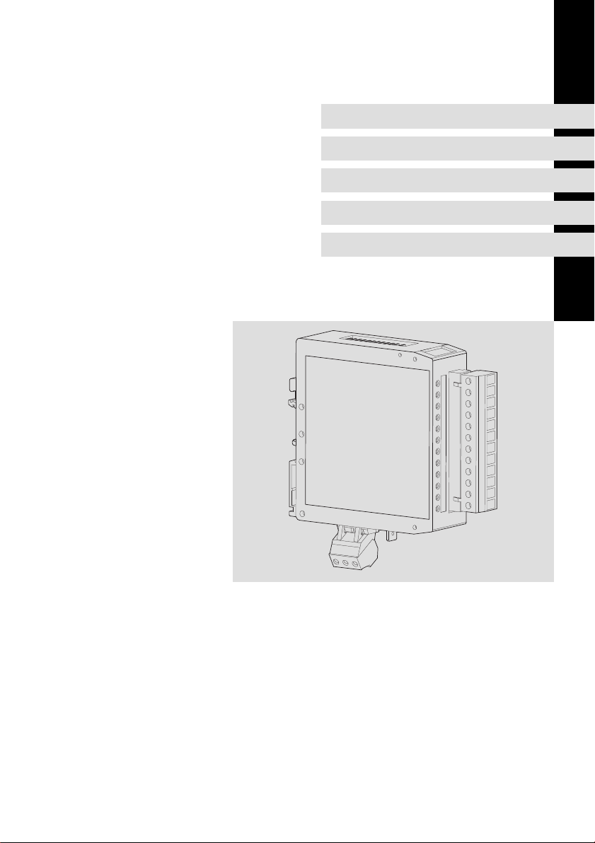
EMZ
EMZ9374IB
Klemmenerweiterung
Terminal extension
Extension bornier
l
Page 2

, Lesen Sie zuerst diese Anleitung und die Dokumentation zum
Grundgerät, bevor Sie mit den Arbeiten beginnen!
Beachten Sie die enthaltenen Sicherheitshinweise.
, Please read these instructions and the documentation of the standard
device before you start working!
Observe the safety instructions given therein!
, Lire le présent fascicule et la documentation relative à l’appareil de base
avant toute manipulation de l’équipement !
Respecter les consignes de sécurité fournies.
Page 3
6
GND
LO
01
I/O 1
I/O 2
I/O 3
2
3
I/O 4
I/O 5
I/O 6
I/O 7
I/O 8
OUT 24V
24V
GND
GND
54
HI
9374_001
Page 4

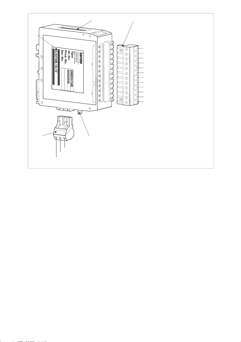
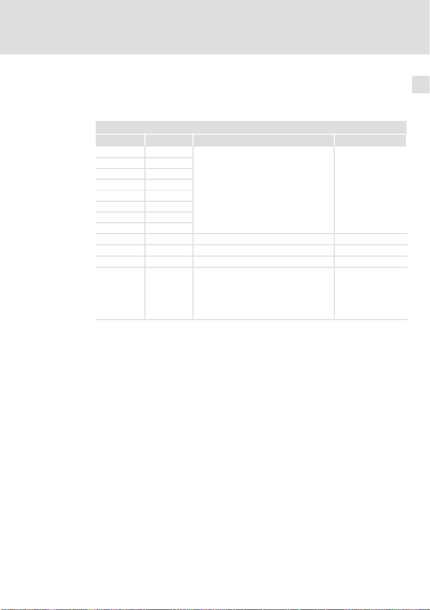
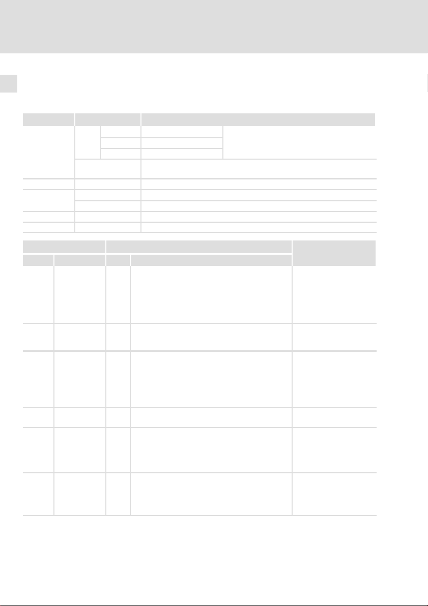
Legende zur Abbildung auf der Ausklappseite
Pos. Beschreibung Ausführliche
Information
0 DIP−Schalter zur Konfiguration ^ 20
1 12−polige Klemmenleiste, Anschluss für
l digitale Eingänge und Ausgänge
l Versorgungsspannung der digitalen Ausgänge
l Versorgungsspannung der Klemmenerweiterung
l Bezugspotential der Klemmen OUT24V und 24V
^ 14
2 LED−Statusanzeigen für I/O1 ... I/O8 ^ 30
3 LED−Statusanzeigen zur Diagnose
l ERROR
l ERROR Modul
l Mode
l Betrieb
^ 30
4 3−polige Klemmenleiste für Systembus (CAN) ^ 18
5 PE−Anbindung
6 Typenschild
0Abb. 0Tab. 0
4
l
EDBMZ9374X DE/EN/FR 4.2
Page 5

Inhalt i
1 Über diese Dokumentation 6 . . . . . . . . . . . . . . . . . . . . . . . . . . . . . . . . . . . . . . . . .
1.1 Verwendete Konventionen 7 . . . . . . . . . . . . . . . . . . . . . . . . . . . . . . . . . . .
1.2 Verwendete Hinweise 8 . . . . . . . . . . . . . . . . . . . . . . . . . . . . . . . . . . . . . . .
2 Sicherheitshinweise 9 . . . . . . . . . . . . . . . . . . . . . . . . . . . . . . . . . . . . . . . . . . . . . . .
3 Produktbeschreibung 10 . . . . . . . . . . . . . . . . . . . . . . . . . . . . . . . . . . . . . . . . . . . . .
3.1 Funktion 10 . . . . . . . . . . . . . . . . . . . . . . . . . . . . . . . . . . . . . . . . . . . . . . . . . .
3.2 Bestimmungsgemäße Verwendung 10 . . . . . . . . . . . . . . . . . . . . . . . . . . . .
3.3 Lieferumfang 10 . . . . . . . . . . . . . . . . . . . . . . . . . . . . . . . . . . . . . . . . . . . . . .
3.4 Identifikation 11 . . . . . . . . . . . . . . . . . . . . . . . . . . . . . . . . . . . . . . . . . . . . . .
3.5 Hinweise zu Funktion und Kompatibilität der Gerätestände 11 . . . . . . . .
4 Technische Daten 12 . . . . . . . . . . . . . . . . . . . . . . . . . . . . . . . . . . . . . . . . . . . . . . . . .
5 Mechanische Installation 13 . . . . . . . . . . . . . . . . . . . . . . . . . . . . . . . . . . . . . . . . . . .
6 Elektrische Installation 14 . . . . . . . . . . . . . . . . . . . . . . . . . . . . . . . . . . . . . . . . . . . . .
6.1 Verdrahtung bei Betrieb von Ein− und Ausgängen 14 . . . . . . . . . . . . . . . .
6.2 Verdrahtung bei Betrieb nur von Eingängen 16 . . . . . . . . . . . . . . . . . . . . .
6.3 Verdrahtung bei Betrieb nur von Ausgängen 17 . . . . . . . . . . . . . . . . . . . .
6.4 Systembus (CAN) verdrahten 18 . . . . . . . . . . . . . . . . . . . . . . . . . . . . . . . . .
7 Inbetriebnahme 19 . . . . . . . . . . . . . . . . . . . . . . . . . . . . . . . . . . . . . . . . . . . . . . . . . .
7.1 Erstes Einschalten 19 . . . . . . . . . . . . . . . . . . . . . . . . . . . . . . . . . . . . . . . . . .
7.2 Einstellungen am Antriebsregler 19 . . . . . . . . . . . . . . . . . . . . . . . . . . . . . .
7.3 Konfiguration mit internen DIP−Schaltern 20 . . . . . . . . . . . . . . . . . . . . . . .
7.3.1 Einstellungen im Programmiermodus 21 . . . . . . . . . . . . . . . . .
7.3.2 Einstellungen im Betriebsmodus (Normalbetrieb) 22 . . . . . . .
7.4 Konfiguration mit Global Drive Control (GDC) 26 . . . . . . . . . . . . . . . . . . .
7.9 Codetabelle 28 . . . . . . . . . . . . . . . . . . . . . . . . . . . . . . . . . . . . . . . . . . . . . . .
8 Fehlersuche und Störungsbeseitigung 30 . . . . . . . . . . . . . . . . . . . . . . . . . . . . . . . .
8.1 Statusmeldungen der Klemmenerweiterung 30 . . . . . . . . . . . . . . . . . . . .
8.2 Störungsmeldungen 31 . . . . . . . . . . . . . . . . . . . . . . . . . . . . . . . . . . . . . . . .
9 Anwendungsbeispiele 34 . . . . . . . . . . . . . . . . . . . . . . . . . . . . . . . . . . . . . . . . . . . . .
9.1 Antriebsregler 93XX mit einer Klemmenerweiterung 34 . . . . . . . . . . . . .
9.2 Antriebsregler 93XX mit zwei Klemmenerweiterungen 38 . . . . . . . . . . . .
EDBMZ9374X DE/EN/FR 4.2
l
5
Page 6

Über diese Dokumentation1
1 Über diese Dokumentation
Inhalt
Diese Dokumentation
ƒ dient dem sicheren und fehlerfreien Arbeiten an und mit der
Klemmenerweiterung EMZ9374IB.
ƒ müssen alle Personen, die an und mit der Klemmenerweiterung
EMZ9374IB arbeiten, verfügbar haben und die für sie relevanten Angaben
und Hinweise beachten.
ƒ muss stets komplett und in einwandfrei lesbarem Zustand sein.
Informationen zur Gültigkeit
Zubehör Typenbezeichnung ab Hardwarestand ab Softwarestand
Klemmenerweiterung EMZ9374IB 0B 01
Zielgruppe
Diese Dokumentation wendet sich an Personen, die das beschriebene Produkt
nach Projektvorgabe installieren und in Betrieb nehmen.
6
I Tipp!
Dokumentationen und Software−Updates zu weiteren Lenze
Produkten finden Sie im Internet im Bereich "Services &
Downloads" unter
http://www.Lenze.com
Dokumenthistorie
Materialnummer Version Beschreibung
.>4y 4.2 02/2010 TD34 Umfirmierung
13291988 4.1 11/2009 TD00 Änderung der Dokumentstruktur
13291988 4.0 07/2009 TD34 Neuauflage wegen Neuorganisation des
00454063 3.0 06/2002 TD23 Umfirmierung
00426046 2.0 04/2002 TD23 Komplett überarbeitete Auflage
00423391 – 08/2001 TD00 Ergänzende Informationen zur Erstauflage
00421659 – 06/2001 TD23 Ergänzende Informationen zur Erstauflage
00401029 1.0 – – Erstauflage
l
Unternehmens
nur für Gerätestand 33.9374IB.1A.10
EDBMZ9374X DE/EN/FR 4.2
Page 7

Über diese Dokumentation
Verwendete Konventionen
1
1.1 Verwendete Konventionen
Diese Dokumentation verwendet folgende Konventionen zur Unterscheidung
verschiedener Arten von Information:
Informationsart Auszeichnung Beispiele/Hinweise
Zahlenschreibweise
Dezimaltrennzeichen Punkt Es wird generell der Dezimalpunkt
Symbole
Seitenverweis ^ Verweis auf eine andere Seite mit
verwendet.
Beispiel: 1234.56
zusätzlichen Informationen
Beispiel: ^ 16 = siehe Seite 16
EDBMZ9374X DE/EN/FR 4.2
l
7
Page 8

1
Über diese Dokumentation
Verwendete Hinweise
1.2 Verwendete Hinweise
Um auf Gefahren und wichtige Informationen hinzuweisen, werden in dieser
Dokumentation folgende Piktogramme und Signalwörter verwendet:
Sicherheitshinweise
Aufbau der Sicherheitshinweise:
} Gefahr!
(kennzeichnet die Art und die Schwere der Gefahr)
Hinweistext
(beschreibt die Gefahr und gibt Hinweise, wie sie vermieden werden
kann)
Piktogramm und Signalwort Bedeutung
{ Gefahr!
} Gefahr!
( Stop!
Anwendungshinweise
Gefahr von Personenschäden durch gefährliche elektrische Spannung
Hinweis auf eine unmittelbar drohende Gefahr, die den
Tod oder schwere Verletzungen zur Folge haben kann,
wenn nicht die entsprechenden Maßnahmen getroffen
werden.
Gefahr von Personenschäden durch eine allgemeine
Gefahrenquelle
Hinweis auf eine unmittelbar drohende Gefahr, die den
Tod oder schwere Verletzungen zur Folge haben kann,
wenn nicht die entsprechenden Maßnahmen getroffen
werden.
Gefahr von Sachschäden
Hinweis auf eine mögliche Gefahr, die Sachschäden zur
Folge haben kann, wenn nicht die entsprechenden Maßnahmen getroffen werden.
Piktogramm und Signalwort Bedeutung
) Hinweis!
I Tipp!
,
8
Wichtiger Hinweis für die störungsfreie Funktion
Nützlicher Tipp für die einfache Handhabung
Verweis auf andere Dokumentation
l
EDBMZ9374X DE/EN/FR 4.2
Page 9

2 Sicherheitshinweise
} Gefahr!
Wenn Sie die folgenden grundlegenden Sicherheitsmaßnahmen
missachten, kann dies zu schweren Personenschäden und
Sachschäden führen:
ƒ Lenze−Antriebskomponenten ...
– ... ausschließlich bestimmungsgemäß verwenden.
– ... niemals trotz erkennbarer Schäden in Betrieb nehmen.
– ... niemals technisch verändern.
– ... niemals unvollständig montiert in Betrieb nehmen.
– ... niemals ohne erforderliche Abdeckungen betreiben.
– ... können während des Betriebs − ihrer Schutzart entsprechend −
spannungsführende, auch bewegliche oder rotierende Teile haben.
Oberflächen können heiß sein.
ƒ Für Lenze−Antriebskomponenten ...
– ... nur das zugelassene Zubehör verwenden.
– ... nur Original−Ersatzteile des Herstellers verwenden.
ƒ Alle Vorgaben der beiliegenden und zugehörigen Dokumentation
beachten.
– Dies ist Voraussetzung für einen sicheren und störungsfreien Betrieb
sowie für das Erreichen der angegebenen Produkteigenschaften.
– Die in diesem Dokument dargestellten verfahrenstechnischen Hinweise
und Schaltungsausschnitte sind Vorschläge, deren Übertragbarkeit auf
die jeweilige Anwendung überprüft werden muss. Für die Eignung der
angegebenen Verfahren und Schaltungsvorschläge übernimmt der
Hersteller keine Gewähr.
ƒ Alle Arbeiten mit und an Lenze−Antriebskomponenten darf nur
qualifiziertes Fachpersonal ausführen.
Nach IEC 60364 bzw. CENELEC HD 384 sind dies Personen, ...
– ... die mit Aufstellung, Montage, Inbetriebsetzung und Betrieb des
Produkts vertraut sind.
– ... die über die entsprechenden Qualifikationen für ihre Tätigkeit
verfügen.
– ... die alle am Einsatzort geltenden Unfallverhütungsvorschriften,
Richtlinien und Gesetze kennen und anwenden können.
Sicherheitshinweise 2
EDBMZ9374X DE/EN/FR 4.2
l
9
Page 10

3
Produktbeschreibung
Funktion
3 Produktbeschreibung
3.1 Funktion
Mit der Klemmenerweiterung EMZ9374IB können Sie die digitalen Ein− und
Ausgangsklemmen der Lenze Antriebsregler erweitern. Die Klemmen
I/O1 I/O8 können wahlweise als Eingang oder Ausgang programmiert
werden. Die Kommunikation zwischen Klemmenerweiterungen und Antriebsregler erfolgt über Systembus (CAN).
Bis zu 4 Klemmenerweiterungen können über eine Adresse angesprochen werden.
Die Konfiguration der Klemmenerweiterung kann entweder geräteintern mit
DIP−Schalter oder komfortabel über Codestellen mit Global Drive Control (GDC)
erfolgen.
3.2 Bestimmungsgemäße Verwendung
Die Klemmenerweiterung ist eine Zubehör−Baugruppe, die mit folgenden Lenze
Grundgeräten eingesetzt werden kann:
ƒ Servo−Umrichter der Gerätereihe 9300
ƒ Frequenzumrichter 9300 vector control
ƒ Servo PLC 9300
ƒ Drive PLC
ƒ Frequenzumrichter 8200 vector
ƒ Frequenzumrichter 8200 motec
Jede andere Verwendung gilt als sachwidrig!
3.3 Lieferumfang
Lieferumfang Wichtig
l 1 Klemmenerweiterung EMZ9374IB
l 1 Betriebsanleitung
l 2 Busabschlusswiderstände (120 W)
l 1 Klemmenleiste 12−polig zum Anschluss der
Ein−/ Ausgänge und an die DC−Spannungsversorgung
l 1 Klemmenleiste 3−polig zum Anschluss an
den Systembus (CAN)
10
Überprüfen Sie nach Erhalt der Lieferung sofort,
ob der Lieferumfang mit den Warenbegleitpapieren übereinstimmt. Für nachträglich reklamierte Mängel übernimmt Lenze keine Gewährleistung.
Reklamieren Sie
l erkennbare Transportschäden sofort beim
Anlieferer.
l erkennbare Mängel/Unvollständigkeit sofort
bei der zuständigen Lenze−Vertretung.
l
EDBMZ9374X DE/EN/FR 4.2
Page 11
Produktbeschreibung
Identifikation
3
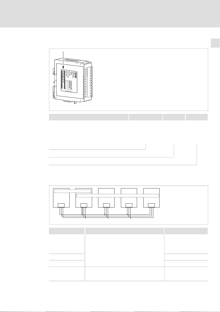
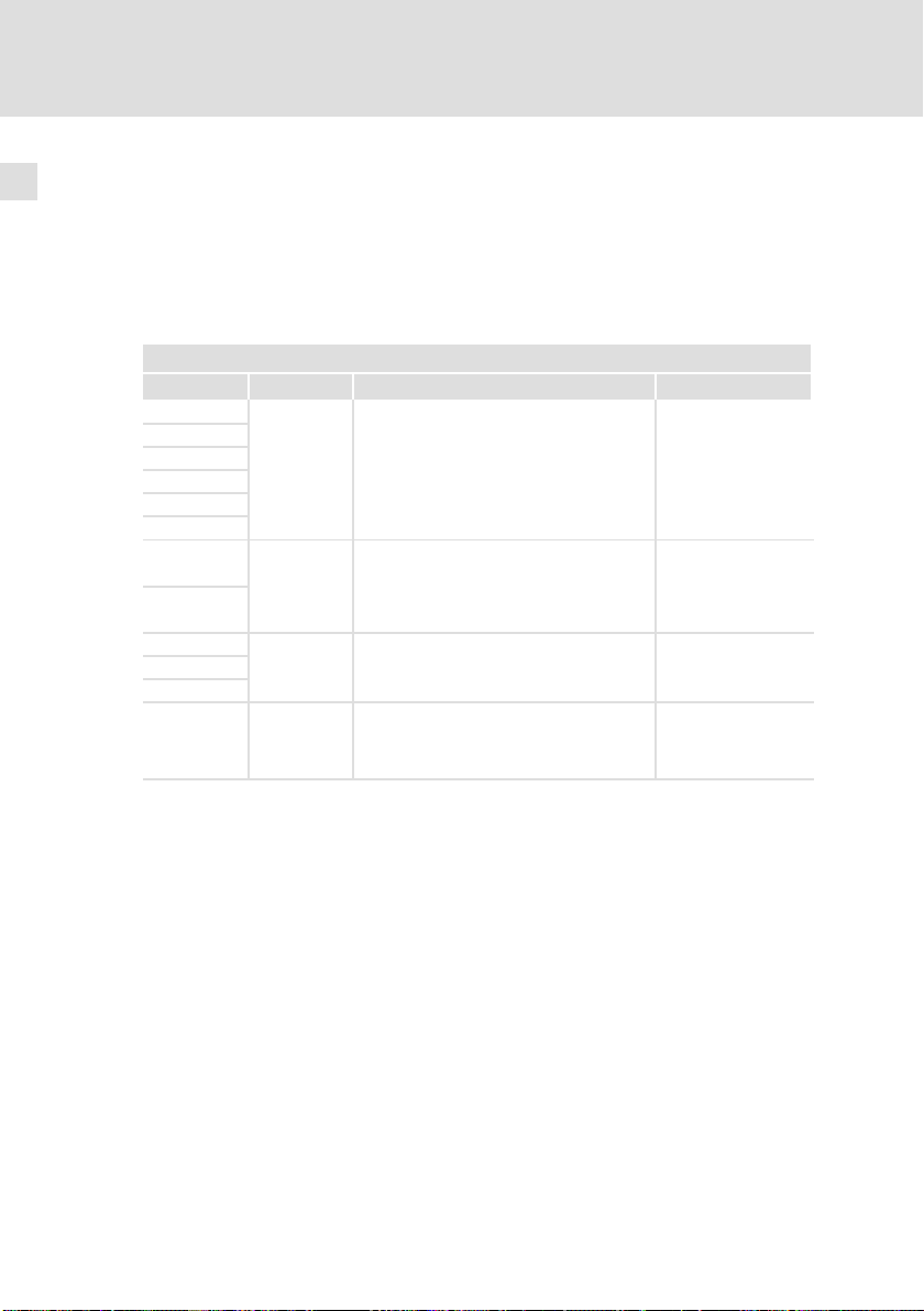
3.4 Identifikation
33.9374IB xx xx
33.9374IB 0B 01
33.9374IB 0C 02
33.9374IB 0C 05
33.9374IB 1A 10
Typ
Hardwarestand
Softwarestand
3.5 Hinweise zu Funktion und Kompatibilität der Gerätestände
9374_011
CAN
Gerätestand Funktion Kompatibilität
33.9374IB.0B.01
33.9374IB.0C.02 Keine Einschränkung
33.9374IB.0C.05 Keine Einschränkung
33.9374IB.1A.10 Betrieb von Ein− und Ausgängen ohne beson-
EDBMZ9374X DE/EN/FR 4.2
SlaveMaster
9374-Master 9374-Slave1 9374-Slave2 9374-Sla ve3
9374 9374 9374 9374
CAN CAN CAN CAN
Bei Betrieb von Ein− und Ausgängen können die
Ausgänge auch bei abgeschalteter Versorgungsspannung Spannung führen. Abhilfe:
l Betrieb nur von Eingängen
l Betrieb nur von Ausgängen
l Besondere Verdrahtung bei Betrieb von Ein−
und Ausgängen siehe
dere Maßnahmen möglich.
l Verdrahtung siehe ^ 15.
^ 14.
l
9374_012
Kein Betrieb als
9374−Slave möglich. Fehlerhafte Ansteuerung der
Klemmenerweiterung.
Keine Einschränkung
11
Page 12

Technische Daten4
4 Technische Daten
Allgemeine Daten
Bereich Werte
Elektrischer Anschluss
Digitale Ausgänge
Digitale Eingänge
Systembus (CAN)
Gewicht 110 g
Versorgungsspannung +18 ... +30 VDC
Stromaufnahme 80 mA bei +24 VDC
Eigenschaften l keine galvanische Trennung
Strom pro Ausgang max. 1 A
HIGH−Pegel +13 ... +30 VDC
LOW−Pegel 0 ... +5 VDC
Eigenschaften keine galvanische Trennung
Eingangswiderstand 3 kW ... 4 kW
HIGH−Pegel +13 ... +30 VDC
LOW−Pegel 0 ... +5 VDC
Protokoll angelehnt an CANopen
Kommunikationsmedium DIN ISO 11898
Netzwerk−Topologie Linie
Systembus−Teilnehmer Slave
max. Anzahl Teilnehmer 63
Baudrate [kBit/s] 20 50 125 250 500 1000
max. Buslänge [m] 2500 1000 500 250 80 25
l kurzschlussfest
(abgestimmt auf die Automatisierungskomponenten von Lenze)
(beidseitig abgeschlossen mit 120 W)
12
Einsatzbedingungen
Umgebungsbedingungen
Klimatisch
Lagerung
Transport IEC/EN 60721−3−2 2K3 (−25 ... +70 °C)
Betrieb IEC/EN 60721−3−3 3K3 (0 ... +55 °C)
Feuchtebeanspruchung
Schutzart
Wartung
IEC/EN 60721−3−1 1K3 (−25 ... +70 °C)
Feuchteklasse F ohne Betauung (mittlere relative Feuchte 85 %)
IP20
wartungsfrei
l
EDBMZ9374X DE/EN/FR 4.2
Page 13
5 Mechanische Installation
( Stop!
Verwenden Sie die Klemmenerweiterung nur als Einbaugerät!
) Hinweis!
Die Montage der Klemmenerweiterung erfolgt auf einer 35 mm
Hutschiene.
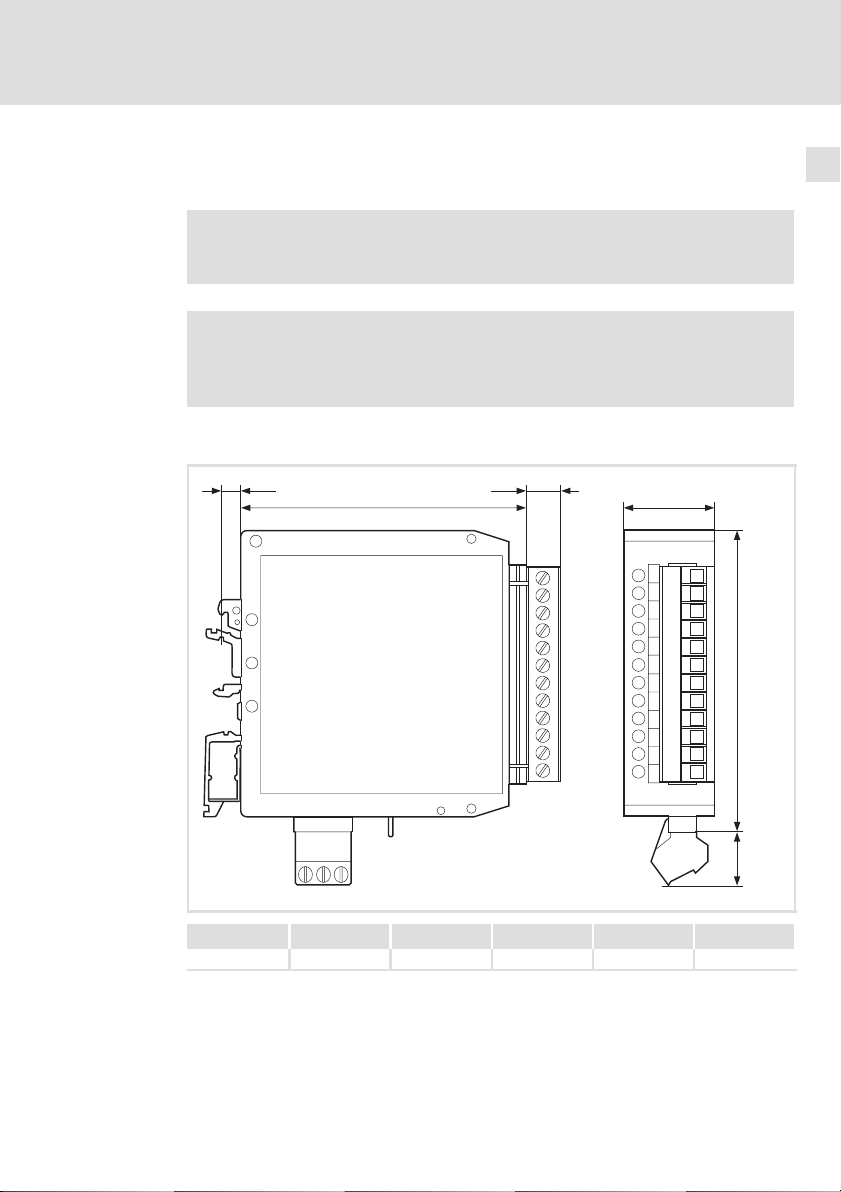
Abmessungen
Mechanische Installation 5
fe
ab
c
d
9374_010
a [mm] b [mm] c [mm] d [mm] e [mm] f [mm]
78 25 84 17 10 5
EDBMZ9374X DE/EN/FR 4.2
l
13
Page 14
6
Elektrische Installation
Verdrahtung bei Betrieb von Ein− und Ausgängen
6 Elektrische Installation
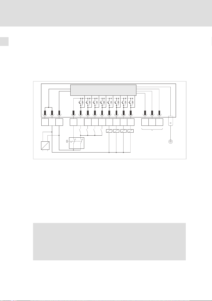
6.1 Verdrahtung bei Betrieb von Ein− und Ausgängen
ƒ Diese Verdrahtung ist erforderlich für die Gerätestände:
– 33.9374IB.0B.01, 33.9374IB.0C.02, 33.9374IB.0C.05
mC
GND I/O1
GND24V
-+
–
0
~
0 Stromversorgung mit +24 VDC Ausgangsspannung.
1 Not−Aus−Schalter
2 Digitale Eingänge mit Schließer
3 Digitale Ausgänge mit Verbraucher
4 Systembus (CAN) (
5 PE−Anschluss (6.3 mm AMP−Stecker)
OUT
24V
I/O2
I/O3
2
I/O6 GND
I/O4 I/O5
I/O8
I/O7
34 5
1
l Berücksichtigen Sie bei der Auslegung der Stromversorgung die Ströme an den
Ausgängen (max. 1 A pro Ausgang).
l Es muss sichergestellt sein, dass bei Betätigung die Ausgänge keine Spannung
führen und die Eingänge keinen HIGH−Pegel erhalten.
^ 18 )
l Verbinden Sie den PE−Anschluss mit der leitfähigen Rückwand des
Schaltschranks. Dadurch wird ein störungsfreier Betrieb der
Klemmenerweiterung gewährleistet.
{ Gefahr!
Installieren Sie eine zusätzliche Potentialtrennung, wenn
ƒ die Klemmenerweiterung mit einem Leitrechner verbunden wird,
ƒ eine sichere Potentialtrennung (doppelte Trennstrecke) nach
EN 50178 erforderlich ist.
LO
HI
PE
9374_013
14
l
EDBMZ9374X DE/EN/FR 4.2
Page 15

Elektrische Installation
Verdrahtung bei Betrieb von Ein− und Ausgängen
ƒ Verwenden Sie diese Verdrahtung ab dem Gerätestand 33.9374IB.1A.10.
mC
6
GND I/O1
GND24V
-+
–
0
~
0 Stromversorgung mit +24 VDC Ausgangsspannung.
1 Not−Aus−Schalter
2 Digitale Eingänge mit Schließer
3 Digitale Ausgänge mit Verbraucher
4 Systembus (CAN) (
5 PE−Anschluss (6.3 mm AMP−Stecker)
OUT
24V
I/O2
I/O3
2
I/O6 GND
I/O4 I/O5
I/O8
I/O7
34 5
1
l Berücksichtigen Sie bei der Auslegung der Stromversorgung die Ströme an den
Ausgängen (max. 1 A pro Ausgang).
l Es muss sichergestellt sein, dass bei Betätigung die Ausgänge keine Spannung
führen.
^ 18 )
l Verbinden Sie den PE−Anschluss mit der leitfähigen Rückwand des
Schaltschranks. Dadurch wird ein störungsfreier Betrieb der
Klemmenerweiterung gewährleistet.
{ Gefahr!
Installieren Sie eine zusätzliche Potentialtrennung, wenn
ƒ die Klemmenerweiterung mit einem Leitrechner verbunden wird,
ƒ eine sichere Potentialtrennung (doppelte Trennstrecke) nach
EN 50178 erforderlich ist.
LO
HI
PE
9374_015
EDBMZ9374X DE/EN/FR 4.2
l
15
Page 16
6
Elektrische Installation
Verdrahtung bei Betrieb nur von Eingängen
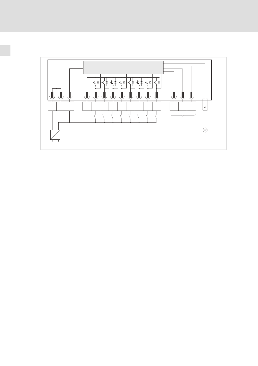
6.2 Verdrahtung bei Betrieb nur von Eingängen
mC
OUT
24V
I/O2
I/O3
I/O4 I/O5
1
^ 18 )
l Verbinden Sie den PE−Anschluss mit der leitfähigen Rückwand des
Schaltschranks. Dadurch wird ein störungsfreier Betrieb der
Klemmenerweiterung gewährleistet.
GND I/O1
GND24V
-+
–
0
~
0 Stromversorgung mit +24 VDC Ausgangsspannung.
1 Digitale Eingänge mit Schließer
2 Systembus (CAN) (
3 PE−Anschluss (6.3 mm AMP−Stecker)
I/O6 GND
I/O8
I/O7
LO
HI
23
PE
9374_016
16
l
EDBMZ9374X DE/EN/FR 4.2
Page 17
Elektrische Installation
Verdrahtung bei Betrieb nur von Ausgängen
6
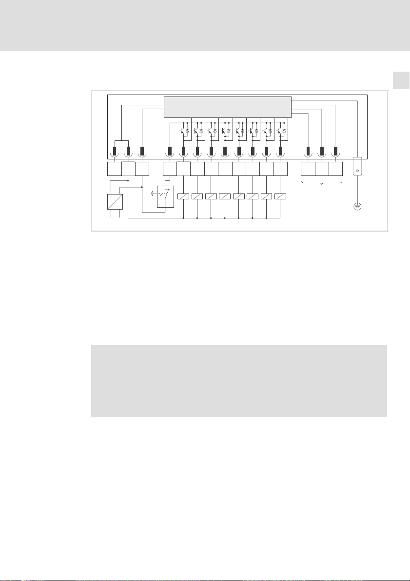
6.3 Verdrahtung bei Betrieb nur von Ausgängen
mC
GND I/O1
GND24V
-+
–
0
~
0 Stromversorgung mit +24 VDC Ausgangsspannung.
1 Not−Aus−Schalter
2 Digitale Ausgänge mit Verbraucher
3 Systembus (CAN) (^ 18 )
4 PE−Anschluss (6.3 mm AMP−Stecker)
OUT
24V
I/O2
I/O3
I/O6 GND
I/O4 I/O5
1
l Berücksichtigen Sie bei der Auslegung der Stromversorgung die Ströme an den
Ausgängen (max. 1 A pro Ausgang).
l Es muss sichergestellt sein, dass bei Betätigung die Ausgänge keine Spannung
führen.
l Verbinden Sie den PE−Anschluss mit der leitfähigen Rückwand des
Schaltschranks. Dadurch wird ein störungsfreier Betrieb der
Klemmenerweiterung gewährleistet.
I/O7
I/O8
LO
HI
34
2
PE
9374_017
{ Gefahr!
EDBMZ9374X DE/EN/FR 4.2
Installieren Sie eine zusätzliche Potentialtrennung, wenn
ƒ die Klemmenerweiterung mit einem Leitrechner verbunden wird,
ƒ eine sichere Potentialtrennung (doppelte Trennstrecke) nach
EN 50178 erforderlich ist.
l
17
Page 18
6
Elektrische Installation
Systembus (CAN) verdrahten
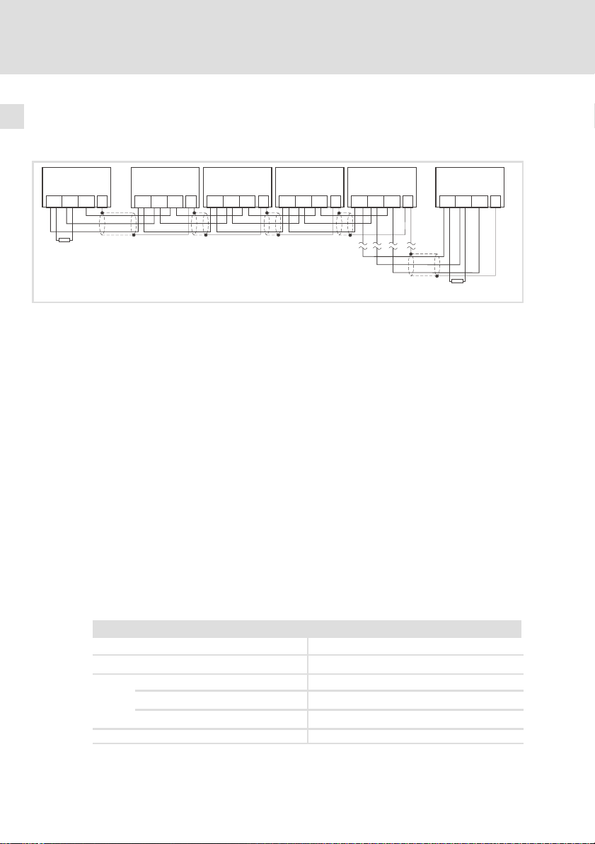
6.4 Systembus (CAN) verdrahten
Prinzipieller Aufbau
A
1
GNDLOHI PE
120 W
A
2
9374-Master
GNDLOHI PE
A
1
A
2
A
n
9374−Slave1 ... 9374−Slave3 kommunizieren nur mit 9374−Master (Busteilnehmer A
9374-Slave1
Busteilnehmer 1 (Antriebsregler)
Busteilnehmer 2 (9374−Master)
Busteilnehmer n (n = max. 63)
ƒ Verbinden Sie nur Klemmen gleichen Signaltyps miteinander.
ƒ Anschluss der Busabschlusswiderstände:
– Je ein Widerstand 120 W am 1. und am letzen Busteilnehmer.
Eigenschaften:
ƒ CAN−basierend mit Busprotokoll nach CANopen (CAL−based
Communication Profile DS301)
ƒ Busausdehnung:
– 25 m bei max. 1 Mbit/s Datenübertragungsrate
– bis zu 1 km bei vermindeter Datenübertragungsgeschwindigkeit
ƒ Sehr zuverlässige Datenübertragung (Hamming−Distanz = 6)
ƒ Signalpegel nach ISO 11898
ƒ Bis zu 63 Busteilnehmer möglich
Spezifikation des Übertragungskabels
Wir empfehlen CAN−Kabel nach ISO 11898−2 zu verwenden:
GNDLOHI PE
9374-Slave2
GNDLOHI PE
9374-Slave3
GNDLOHI PE
A
n
GNDLOHI PE
120 W
9374_005
)
2
18
CAN−Kabel nach ISO 11898−2
Kabeltyp Paarverseilt mit Abschirmung
Impedanz
Leitungswiderstand
Kabellänge £ 300 m
Kabellänge £ 1000 m
Signallaufzeit £ 5 ns/m
120 W (95 ... 140 W)
£ 70 mW/m
£ 40 mW/m
l
EDBMZ9374X DE/EN/FR 4.2
Page 19

7 Inbetriebnahme
7.1 Erstes Einschalten
Für die Inbetriebnahme ist eine vollständige Verdrahtung des Systembus (CAN)
notwendig.
( Stop!
Überprüfen Sie vor dem Einschalten der Versorgungsspannung
ƒ die gesamte Verdrahtung auf Vollständigkeit und Kurzschluss,
ƒ ob das Bussystem beim physikalisch ersten und letzten
Busteilnehmer abgeschlossen ist.
7.2 Einstellungen am Antriebsregler
ƒ Für die Kommunikation zwischen Antriebsregler (Master) und
Klemmenerweiterung (Slave) müssen Sie ggf. Codestellen am
Antriebsregler parametrieren.
ƒ Führen Sie die Parametrierung der Codestellen anhand der
Betriebsanleitung des Antriebsreglers durch.
Inbetriebnahme
Erstes Einschalten
7
Überwachung bei Kommunikationsstörung (Unterbrechung der Signalleitung)
( Stop!
Beim Betrieb des Systembus mit zyklischer Prozessdatenübergabe können Sie
eine Überwachungszeit einstellen. Bei einer Kommunikationsstörung schalten
nach Ablauf der Überwachungszeit die digitalen Ausgänge auf LOW−Pegel, und
eine Störungsmeldung erfolgt.
ƒ Stellen Sie am Antriebsregler die zyklischer Prozessdatenübergabe für den
Systembus ein.
ƒ Einstellen der Systembus−Überwachungszeit an den
Klemmenerweiterungen: (¶ 26)
EDBMZ9374X DE/EN/FR 4.2
Beim Betrieb des Systembus mit ereignisgesteuerter
Prozessdatenübergabe (Lenze−Einstellung) ist keine Überwachung
möglich. Die digitalen Ausgänge der Klemmenerweiterungen
schalten bei einer Kommunikationsstörung nicht definiert auf
LOW−Pegel. Der zuletzt ausgegebene Zustand an den Ausgängen
wird beibehalten.
l
19
Page 20

7
7.3 Konfiguration mit internen DIP−Schaltern
Inbetriebnahme
Konfiguration mit internen DIP−Schaltern
Überwachung bei BUS−OFF (Kurzschluss der Signalleitung)
Ein BUS−OFF wird immer überwacht. Die digitalen Ausgänge der Klemmenerweiterungen schalten auf LOW−Pegel.
) Hinweis!
ƒ Ziehen Sie die 3pol. Klemmenleiste des Systembus (CAN)
während der Einstellungen im Betriebs− und Programmiermodus
von der Klemmenerweiterung ab, um Störungen auf dem
Systembus zu vermeiden.
ƒ Halten Sie die vorgegebene Einstellreihenfolge ein, um Fehler
während der Konfiguration zu vermeiden!
Einstellreihenfolge:
1. Einstellungen im Programmiermodus
2. Einstellungen im Betriebsmodus (Normalbetrieb)
– Adressierung der Klemmenerweiterung
– Anzahl der verwendeten Klemmenerweiterungen
– Einstellen der CAN−Bus Baudrate
20
l
EDBMZ9374X DE/EN/FR 4.2
Page 21
Inbetriebnahme
Konfiguration mit internen DIP−Schaltern
Einstellungen im Programmiermodus
7
7.3.1 Einstellungen im Programmiermodus
Im Programmiermodus konfigurieren Sie die digitalen Ein− und Ausgänge (Klemmen I/O1 ... I/O8).
Belegung der DIP−Schalter im Programmiermodus
DIP−Schalter Funktion Hinweise zur Einstellung Anmerkung
1 Klemme I/O1
2 Klemme I/O2
3 Klemme I/O3
4 Klemme I/O4
5 Klemme I/O5
6 Klemme I/O6
7 Klemme I/O7
8 Klemme I/O8
9 – Stellen Sie den DIP−Schalter auf OFF
10 – Stellen Sie den DIP−Schalter auf OFF
11 – Stellen Sie den DIP−Schalter auf OFF
12 Programmier-
modus /
Betriebsmo-
dus
Stellen Sie die DIP−Schalter entsprechend
der Beschaltung der Klemmen I/O1 ... I/O8
ein:
l DIP−Schalter auf ON: Klemme als Aus-
gang konfiguriert
l DIP−Schalter auf OFF: Klemme als Ein-
gang konfiguriert
Stellen Sie den DIP−Schalter auf ON
(Programmiermodus)
Einstellreihenfolge:
1. Schalten Sie die Versorgungsspannung für die Klemmenerweiterung ein.
2. Stellen Sie den DIP−Schalter 12 auf ON (Programmiermodus).
3. Konfigurieren Sie die Klemmen I/O1 ... I/O8 mit den DIP−Schaltern 1 ... 8.
4. Stellen Sie den DIP−Schalter 12 auf OFF (Betriebsmodus).
– Die Konfiguration der Ein− /Ausgänge ist abgeschlossen.
5. Schalten Sie die Versorgungsspannung für die Klemmenerweiterung aus.
– Erst durch das Ausschalten der Versorgungsspannung wird der
Programmiermodus verlassen.
Eine Fehlermeldung
erfolgt (LED ERROR"
leuchtet), wenn eine
Klemme als Ausgang
konfiguriert ist und
ein HIGH−Pegel aufgeschaltet wird.
Im Programmiermodus
l blinkt die LED
ERROR Modul"
l erlischt die LED
Betrieb"
EDBMZ9374X DE/EN/FR 4.2
l
21
Page 22
7
Inbetriebnahme
Konfiguration mit internen DIP−Schaltern
Einstellungen im Betriebsmodus (Normalbetrieb)
7.3.2 Einstellungen im Betriebsmodus (Normalbetrieb)
(Einstellungen nur bei ausgeschalteter Versorgungsspannung durchführen!)
Im Betriebsmodus führen Sie folgende Einstellungen durch:
ƒ Adressierung der Klemmenerweiterung
ƒ Anzahl der verwendeten Klemmenerweiterungen
ƒ Einstellen der CAN−Bus Baudrate
Belegung der DIP−Schalter im Betriebsmodus
DIP−Schalter Funktion Hinweise zur Einstellung Anmerkung
Einstellen der
1
CAN−Bus
2
Knotena-
3
dresse
4
5
6
Anzahl Klem-
7
menerweite-
rungen an ei-
8
ner Gerätea-
dresse
Einstellen der
9
Baudrate
10
11
12 Programmier-
modus/
Betriebsmo-
dus
Mit den DIP−Schaltern 1 ... 6 stellen Sie die
Adresse der Klemmenerweiterung ein.
Die Tabelle Adressierung der Klemmenerweiterung" zeigt die Schalterstellungen.
Sie können max. 4 Klemmenerweiterungen
an einer Geräteadresse betreiben.
Die Tabelle Einstellen der Baudrate" zeigt
die Schalterstellungen.
Stellen Sie den DIP−Schalter auf OFF (Betriebsmodus)
Betriebsmodus einstellen:
1. Prüfen Sie, ob der DIP−Schalter 12 auf OFF steht (Betriebsmodus).
2. Schalten Sie die Versorgungsspannung für die Klemmenerweiterung ein.
– Der Betriebsmodus ist aktiv.
Es stehen max. 63
Adressen zur Verfügung.
^ 25
Im Beriebsmodus
leuchtet die LED Betrieb"
22
l
EDBMZ9374X DE/EN/FR 4.2
Page 23
Inbetriebnahme
Konfiguration mit internen DIP−Schaltern
Einstellungen im Betriebsmodus (Normalbetrieb)
Adressierung der Klemmenerweiterung
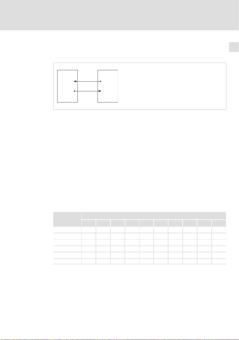
Kommunikation zwischen Klemmenerweiterung und Antriebsregler
7
A
1
CAN-IN
769
CAN-OUT
770
PDO-TX
PDO-RX
A
2
9374C0350 = 1
CAN-OUT
767 + 2 = 769
CAN-IN
768+2=770
9374_006
A
1
A
2
Der Austausch der Ein−/ Ausgangsinformationen erfolgt über den Prozessdatenkanal (PDO = Process Data Object). Zwei Prozessdaten−Telegramme (PDO−TX,
PDO−RX) übermitteln die Informationen. Für die Übermittlung benötigt jedes Telegrammm einen CAN−Bus Identifier, der sich zusammensetzt durch Addition
von Basis Identifier und CAN−Bus Knotenadresse der Klemmenerweiterung
(CAN−Bus Identifier = Basis Identifier + CAN−Bus Knotenadresse).
ƒ PDO−TX: Die Klemmenerweiterung sendet die Zustandsinformationen der
digitalen Eingänge zum Antriebsregler.
Antriebsregler mit CAN−Bus Knotenadresse 1 (C0350 = 1)
Klemmenerweiterung mit CAN−Bus Knotenadresse 2
– Basis Identifier: 767
ƒ PDO−RX: Die Klemmenerweiterung empfängt die Zustandsinformationen
für die digitalen Ausgänge vom Antriebsregler.
– Basis Identifier: 768
DIP−Schalter Adresse
1 2 3 4 5 6 7 8 63
1 ON OFF ON OFF ON OFF ON OFF ... ON
2 OFF ON ON OFF OFF ON ON OFF ... ON
3 OFF OFF OFF ON ON ON ON OFF ... ON
4 OFF OFF OFF OFF OFF OFF OFF ON ... ON
5 OFF OFF OFF OFF OFF OFF OFF OFF ... ON
6 OFF OFF OFF OFF OFF OFF OFF OFF ... ON
ƒ Stellen Sie die Adresse der Klemmenerweiterung mit den DIP−Schaltern
1 ... 6 ein.
EDBMZ9374X DE/EN/FR 4.2
l
23
Page 24
7
Inbetriebnahme
Konfiguration mit internen DIP−Schaltern
Einstellungen im Betriebsmodus (Normalbetrieb)
) Hinweis!
Beachten Sie, dass die Adresse der Klemmenerweiterung um den
Wert 1 höher sein muss als die Adresse des Antriebsreglers.
ƒ In der Lenze−Einstellung hat der Master die Adresse 1 (C0350 = 1).
In diesem Fall stellen Sie die Klemmenerweiterung auf die
Adresse 2.
Anzahl der verwendeten Klemmenerweiterungen
SlaveMaster
9374-Master 9374-Slave1 9374-Slave2 9374-Slave3
9374 9374 9374 9374
CAN
ƒ Die Klemmenerweiterung 9374−Master kommuniziert mit dem
Antriebsregler (Master).
ƒ Mit dem 9374−Master können weitere 3 Klemmenerweiterungen als Slave
(9374−Slave) über den Systembus kommunizieren.
CAN CAN CAN CAN
9374_012
24
DIP−Schalter Anzahl der Klemmenerweiterungen
1* 2 3 4
7 OFF ON OFF ON
8 OFF OFF ON ON
*
Klemmenerweiterung ist immer 9374−Master"
l
EDBMZ9374X DE/EN/FR 4.2
Page 25

Inbetriebnahme
Konfiguration mit internen DIP−Schaltern
Einstellungen im Betriebsmodus (Normalbetrieb)
Einstellen der CAN−Bus Baudrate
DIP−Schalter Baudrate [kBit/s]
1000 500 250 125 100 50 20 10
9 OFF OFF OFF OFF ON ON ON ON
10 OFF OFF ON ON OFF OFF ON ON
11 OFF ON OFF ON OFF ON OFF ON
ƒ Stellen Sie die Baudrate der Klemmenerweiterung mit den DIP−Schaltern
9 ... 11 ein.
– Die Baudrate der Klemmenerweiterung muss mit der Baudrate des
Antriebsreglers (Master) identisch sein.
– In der Lenze−Einstellung hat der Master die Baudrate 500 kBit/s
(C0351 = 0).
) Hinweis!
Die einzustellende Baudrate ist abhängig von der Länge der
Systembusleitung. (¶ 12, Technische Daten)
7
EDBMZ9374X DE/EN/FR 4.2
l
25
Page 26

7
Inbetriebnahme
Konfiguration mit Global Drive Control (GDC)
7.4 Konfiguration mit Global Drive Control (GDC)
Zur Kommunikation mit den Klemmenerweiterungen benötigen Sie das PC−Systembusmodul 2173IB, das an die parallele Schnittstelle Ihres PC angeschlossen
wird.
Schnittstelle amPCÜbertragungs-
parallele
Schnittstelle
(LPT−Port)
medium
Systembus
(CAN)
erforderliche Komponenten Bestellbezeichnung
PC−Systembusmodul inkl.
Anschlussleitung und Spannungsversorgungsadapter
Für DIN−Tastaturanschluss:
l EMF2173IB
Für PS/2−Tastaturanschluss:
l EMF2173IBV002 oder
EMF2173IBV003
) Hinweis!
Die Handhabung und Installation des Systembusmoduls entnehmen
Sie bitte der dem PC−Systembusmodul beiliegenden Kurzanleitung.
Einstellreihenfolge Bemerkung
1. Stellen Sie die Verbindung zwischen
PC und Klemmenerweiterung her.
2. Stellen Sie mit den DIP−Schaltern an
der Klemmenerweiterung die
Adresse ein.
3. Stellen Sie mit den DIP−Schaltern an
der Klemmenerweiterung die Baudrate auf 500 kBit/s ein.
4. Schalten Sie den PC und die Versorgungsspannung für die Klemmenerweiterung ein.
5. Starten Sie das Programm GDC. Das Dialogfeld CAN−Antriebe suchen öffnet sich.
Verbindung nur bei ausgeschalteten Geräten herstellen.
Einstellung: ^ 23
Die Adresse muss > 0 eingestellt sein. Bei Adresse = 0
erfolgt eine Fehlermeldung.
Einstellung: ^ 25
26
l
EDBMZ9374X DE/EN/FR 4.2
Page 27

Konfiguration mit Global Drive Control (GDC)
6. Klicken Sie im Dialogfeld CAN−An-
triebe suchen auf Suchen.
7.
Führen Sie die Konfiguration der
Klemmenerweiterungen über die
Codestellen durch. Z. B.:
l C0010: Konfiguration der digita-
len Ein− und Ausgänge
l C0011: Entprellzeit für die digi-
talen Eingänge
l Stellen Sie eine Systembus−Über-
wachungszeit für die zyklische
Prozessdatenübergabe ein:
– Stellen Sie C0030 > 0 ms ein
– Lenze−Einstellung: 0 ms
– Schrittweite: 100 ms
8. Übertragen Sie den aktuellen Parametersatz zur Klemmenerweiterung
(F5).
9. Die Konfiguration ist abgeschlossen. Entfernen Sie ggf. die Verbindung
zwischen PC und Klemmenerweiterung.
Inbetriebnahme
BemerkungEinstellreihenfolge
GDC identifiziert die Klemmenerweiterung und lädt
automatisch die entsprechende Gerätebeschreibung.
l Wenn kein Gerät gefunden wurde, überprüfen Sie
im GDC die Kommunikationsparameter (
lung: siehe Handbuch Global Drive Control − Erste
Schritte"):
– Der Treiber für Systembus (CAN) muss ausge-
wählt sein.
– Für die Gerätestände 33.9374IB.0B.01,
33.9374IB.0C.02 und 33.9374IB.0C.05 muss Parameterkanal 1 ausgewählt werden. Parameterkanal 2 steht nicht zur Verfügung.
– Ab Gerätestand 33.9374IB.1A.10 stehen Parame-
terkanal 1 und Parameterkanal 2 zur Verfügung.
Eine Auswahl ist nicht erforderlich.
– Lassen Sie GDC erneut nach der Klemmenerwei-
terung suchen.
Zu den Einstellungen siehe Codetabelle. (
l Bei ereignisgesteuerter Prozessdatenübergabe
(Lenze−Einstellung) ist keine Überwachung möglich.
Die digitalen Ausgänge schalten bei einer Kommunikationsstörung (Unterbrechung der Signalleitung) nicht definiert auf LOW−Pegel. Der zuletzt
ausgegebene Zustand an den Ausgängen wird beibehalten.
l Bei zyklischer Prozessdatenübergabe schalten bei
einer Kommunikationsstörung nach Ablauf der
Überwachungszeit die digitalen Ausgänge auf
LOW−Pegel. Eine Störungsmeldung erfolgt.
– Stellen Sie auch am Antriebsregler den System-
bus auf zyklische Prozessdatenübergabe (
l Ein BUS−OFF (Kurzschluss der Signalleitung) wird
immer überwacht. Die digitalen Ausgänge der
Klemmenerweiterungen schalten auf LOW−Pegel.
Verbindung nur bei ausgeschalteten Geräten entfernen.
^ Einstel-
^ 28)
^ 19)
7
EDBMZ9374X DE/EN/FR 4.2
l
27
Page 28
7
Inbetriebnahme
Codetabelle
7.5 Codetabelle
So lesen Sie die Codetabelle
Spalte Abkürzung Bedeutung
Code
Bezeichnung Bezeichnung des Code
Lenze Lenze−Einstellung (Wert bei Auslieferung)
Auswahl 1
WICHTIG − Kurze, wichtige Erläuterungen
Cxxxx Code Cxxxx
1 Subcode 1 von Cxxxx
2 Subcode 2 von Cxxxx
[Cxxxx] Geänderter Parameter des Code wird durch Ausschalten der Versorgungs-
à
{%}
spannung für die Klemmenerweiterung übernommen
Die Spalte "WICHTIG" enthält weitere Information
99 min. Wert {Einheit} max. Wert
Parameterwert wird sofort übernommen (ONLINE)
Code Einstellmöglichkeiten
Nr. Bezeichnung Lenze Auswahl
[C0010] E/A−Richtungs-
umschaltung
Entprellzeit 1 1 {1 ms} 255 Verzögerungzeit für die
C0011
C0012 Abschaltung
der Ereignisübertragung
C0014
Überlagerter
Sendezyklus
C0015 Mindestsende-
pause
C0030 Überwachung
Ausgangsklemmen
0
Bit 0 ... Bit 7
Bit 8 ... Bit 15
Bit 16 ... Bit 23
Bit 24 ... Bit 31
Bitwert 0
Bitwert 1
1
Bit 0 ... Bit 7
Bit 8 ... Bit 15
Bit 16 ... Bit 23
Bit 24 ... Bit 31
Bitwert 0
Bitwert 1
100 100 {1 ms} 65000 Unabhängig von der Ein-
0
0 {1 ms} 255
0 = keine Sendepause
0
0 {100 ms} 25500
0 = keine Überwachung
Ein−/ Ausgänge 9374−Master
Ein−/ Ausgänge 9374−Slave1
Ein−/ Ausgänge 9374−Slave2
Ein−/ Ausgänge 9374−Slave3
Eingang
Ausgang
Ein−/ Ausgänge 9374−Master
Ein−/ Ausgänge 9374−Slave1
Ein−/ Ausgänge 9374−Slave2
Ein−/ Ausgänge 9374−Slave3
Zyklisches Senden
Ereignisgesteuertes Senden
WICHTIG
32 Bit Information
Konfiguration der digitalen Ein−/ Ausgänge
Übernahme der Daten an
den digitalen Eingängen
stellung in C0015
Nur bei ereignisgesteuer-
ter Prozessdatenübergabe wirksam.
Große Sendepausen reduzieren die Buslast.
Bei einer Kommunikationsstörung schalten
nach Ablauf der Überwachungszeit die digitalen
Ausgänge auf LOW−Pegel
28
l
EDBMZ9374X DE/EN/FR 4.2
Page 29

[C0050] BasisId CAN−IN
(dig. OUT)
[C0051] BasisId CAN−
OUT (dig. IN)
C0093 DIS: Geräteer-
kennung
C0099 DIS: Software-
version
C0102 Erkennung zu-
sätzlicher Module
E/A Signalpe-
C0104
gel
C0202
1 EKZ1
2 EKZ2
3 EKZ3
4 EKZ4
Inbetriebnahme
Codetabelle
WICHTIGEinstellmöglichkeitenCode WICHTIG
AuswahlLenzeBezeichnungNr.
768 384 {1} 896 CAN−Bus Identifier für
767 384 {1} 896 CAN−Bus Identifier für
93740000 = Klemmenerweiterung 9374 Nur Anzeige
1000 = Softwarestand 1.0 Nur Anzeige
Erkannte Module (9474−Slave)
0000
kein Modul erkannt
h
Modul Nr. 1 (9374−Slave1)
0001
h
Modul Nr. 2 (9374−Slave2)
0002
h
Modul Nr. 1 und 2 (9374−Slave1 und 2)
0003
h
Modul Nr. 3 (9374−Slave3)
0004
h
Modul Nr. 1 und 3 (9374−Slave1 und 3)
0005
h
0006
Modul Nr. 2 und 3 (9374−Slave2 und 3)
h
0007
Modul Nr. 1, 2 und 3 (9374−Slave1, 2 und
h
3)
Bit 0 ... Bit 7
Bit 8 ... Bit 15
Bit 16 ... Bit 23
Bit 24 ... Bit 31
Bitwert 0
Bitwert 1
Ein−/ Ausgänge 9374−Master
Ein−/ Ausgänge 9374−Slave1
Ein−/ Ausgänge 9374−Slave2
Ein−/ Ausgänge 9374−Slave3
LOW−Signal
HIGH−Signal
das Prozessdaten−Telegramm PDO−RX (Antriebsregler ® Klemmenerweiterung)
das Prozessdaten−Telegramm PDO−TX (Klemmenerweiterung ® Antriebsregler)
Code wird ab Gerätestand 33.9374IB.1A.10
unterstützt
Code wird ab Gerätestand 33.9374IB.1A.10
unterstützt
Nur Anzeige (Hexadezimal)
16 Bit Information
Wird erst nach Einlesen
der Codestelle angezeigt
Nur Anzeige (Hexadezimal)
32 Bit Information
Status der Ein−/Ausgänge
Code wird ab Gerätestand 33.9374IB.1A.10
unterstützt
Interne Gerätekennung
Code wird ab Gerätestand 33.9374IB.1A.10
unterstützt
7
EDBMZ9374X DE/EN/FR 4.2
l
29
Page 30

8
Fehlersuche und Störungsbeseitigung
Statusmeldungen der Klemmenerweiterung
8 Fehlersuche und Störungsbeseitigung
8.1 Statusmeldungen der Klemmenerweiterung
Diagnose LED
ERROR Modul Mode Betrieb Bedeutung
¢ll Normalbetrieb
¢ « l Datenübertragung aktiv
¢ l « Betriebszustand Pre−Operational
« l ¢ Programmiermodus aktiv
« l ¢
« « « Konfigurations− oder Selbsttest−Fehler
ERROR Bedeutung
¢
l
l LED an ¢ LED aus « LED blinkt
Bus−OFF bzw. Kommunikationsstörung:
Die Klemmenerweiterung ist nicht mehr in Betrieb
Keine Störung an den Eingangs−/ Ausgangsklemmen
Fehlerhafte Verdrahtung:
Auf eine als Ausgang konfigurierte Klemme
wurde ein HIGH−Pegel geschaltet.
30
LED der digitalen Eingänge/Ausgänge
I/O1 ... I/O8 Bedeutung
¢ Eingang/Ausgang ist nicht aktiv
l Eingang/Ausgang ist aktiv
l LED an ¢ LED aus
l
EDBMZ9374X DE/EN/FR 4.2
Page 31

Fehlersuche und Störungsbeseitigung
Störungsmeldungen
8
8.2 Störungsmeldungen
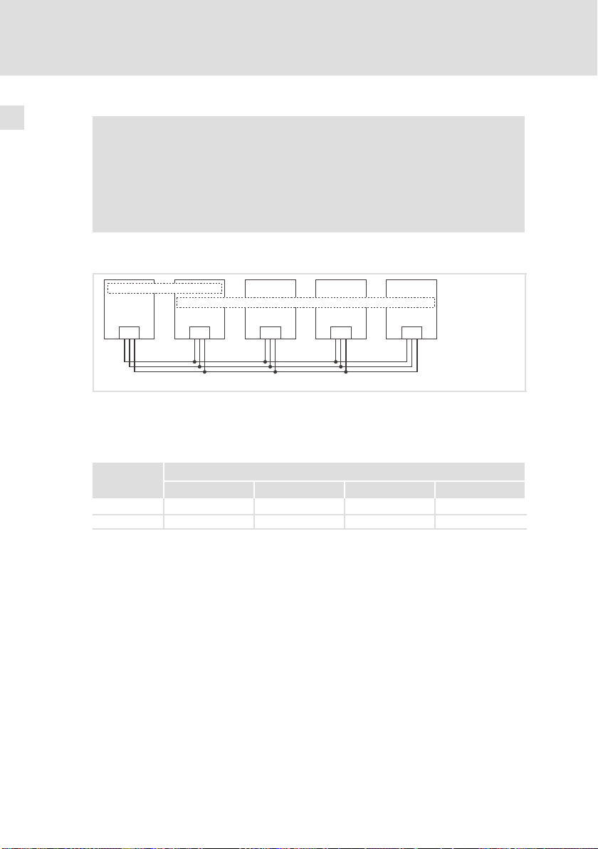
Betrieb von 4 Klemmenerweiterungen an einem Antriebsregler
SlaveMaster
9374-Master 9374-Slave1 9374-Slave2 9374-Sla ve3
0
CAN
0 Antriebsregler
Kommunikationsstörungen
Unterbrechung der Signalleitung zwischen Master und Slave
Unterbrechung der Signalleitung zwischen
Unterbrechung der Signalleitung zwischen 9374 Master und 9374 Slave1
Unterbrechung der Signalleitung zwischen 9374 Master und 9374 Slave2
Unterbrechung der Signalleitung zwischen 9374 Master und 9374 Slave3
BUS−OFF
Kurzschluss der Signalleitung (z. B. CAN−LO/CAN−HI, CAN−HI/CAN−GND)
9374 9374 9374 9374
CAN CAN CAN CAN
l Master und Slave
l 9374 Master und 9374 Slave1 ... 9374 Slave3
9374_008
EDBMZ9374X DE/EN/FR 4.2
l
31
Page 32

8
Fehlersuche und Störungsbeseitigung
Störungsmeldungen
Verhalten der Klemmenerweiterungen bei zyklischer Prozessdatenübergabe
Busteilnehmer
9374−Master
LED ERROR Modul" LED Pegel der di-
Blinktakt Be-
« – – l l LOW
« – – – l l
¢ l l LOW
trieb"
Mode"
gitalen Aus-
gänge
9374−Slave1
9374−Slave2
9374−Slave3
9374−Slave1 « – – l l LOW
9374−Slave2 « – – l l LOW
9374−Slave3 « – – l l LOW
9374−Slave1
9374−Slave2
9374−Slave3
¢ l l LOW
« – – l l LOW
« – – ¢ l LOW
l LED an ¢ LED aus « LED blinkt
Störung Wichtig
l Nur bei C0030 > 0 ms
(Systembus Überwachungszeit) schalten
die digitalen Ausgänge definiert auf
LOW−Pegel.
l Nach Störungsbesei-
tigung kein Reset erforderlich.
l Betrieb nicht gestört.
l LED ERROR Modul"
meldet Störung von
9374−Slave1, 2 oder
3.
l Nach Störungsbesei-
tigung kein Reset erforderlich.
Nach Störungsbeseitigung Reset der Klemmenerweiterung durch
Aus−/Einschalten der
Versorgungsspannung.
l Nur bei C0030 > 0 ms
(Systembus Überwachungszeit) schalten
die digitalen Ausgänge definiert auf
LOW−Pegel.
l Nach Störungsbesei-
tigung kein Reset erforderlich.
Nach Störungsbeseitigung Reset der Klemmenerweiterungen durch
Aus−/Einschalten der
Versorgungsspannung.
32
l
EDBMZ9374X DE/EN/FR 4.2
Page 33

Fehlersuche und Störungsbeseitigung
Störungsmeldungen
Verhalten der Klemmenerweiterungen bei ereignisgesteuerter Prozessdatenübergabe (ohne Überwachung)
Busteilnehmer
9374−Master
9374−Slave1
9374−Slave2
9374−Slave3
9374−Slave1 « – – l l LOW
9374−Slave2 « – – l l LOW
9374−Slave3 « – – l l LOW
9374−Slave1
9374−Slave2
9374−Slave3
LED ERROR Modul" LED Pegel der di-
Blinktakt Be-
¢
« – – – l l
« – – – l l
¢ l l LOW
¢ l l
« – – l l LOW
« – – ¢ l LOW
l LED an ¢ LED aus « LED blinkt
trieb"
l l
Mode"
gitalen Aus-
gänge
Letzter ausgegebener Zustand
Letzter ausgegebener Zustand
Störung Wichtig
l Undefinierter Zu-
stand der digitalen
Ausgänge.
l Nach Störungsbesei-
tigung kein Reset erforderlich.
l Betrieb nicht gestört.
l LED ERROR Modul"
meldet Störung von
9374−Slave1, 2 oder
3.
Nach Störungsbeseitigung Reset der Klemmenerweiterung durch
Aus−/Einschalten der
Versorgungsspannung.
Undefinierter Zustand
der digitalen Ausgänge.
Nach Störungsbeseitigung kein Reset erforderlich.
Nach Störungsbeseitigung kein Reset erforderlich.
Nach Störungsbeseitigung Reset der Klemmenerweiterungen durch
Aus−/Einschalten der
Versorgungsspannung.
8
EDBMZ9374X DE/EN/FR 4.2
l
33
Page 34

9
Anwendungsbeispiele
Antriebsregler 93XX mit einer Klemmenerweiterung
9 Anwendungsbeispiele
9.1 Antriebsregler 93XX mit einer Klemmenerweiterung
An einem Antriebsregler der Gerätereihe 9300 soll eine Klemmenerweiterung
mit 6 Eingängen und 2 Ausgängen betrieben werden.
ƒ Die CAN−Bus Knotenadresse des Antriebsreglers ist 1.
ƒ Die Baudrate soll 500 kBit/s betragen.
ƒ Die Konfiguration der Klemmenerweiterung soll über die internen
DIP−Schalter erfolgen.
Die dargestellte Verdrahtung ist nur gültig für Klemmenerweiterungen ab Gerätestand 33.9374IB.1A.10 (¶ 15)
0
l
1
+18 … +30 VDC
+
=
34
PE
CAN
0 Antriebsregler 93XX
1 Klemmenerweiterung (9374−Master)
l
9374_018
EDBMZ9374X DE/EN/FR 4.2
Page 35

Anwendungsbeispiele
Antriebsregler 93XX mit einer Klemmenerweiterung
Einstellungen am Antriebsregler
(Beachten Sie auch die Angaben im Systemhandbuch zum Antriebsregler)
Einstellreihenfolge:
1. CAN−Bus Knotenadresse auf den Wert 1 stellen (C0350 = 1).
2. Adresse für CAN3−IN und CAN3−OUT soll von C0350 bestimmt werden
(C0353/3 = 0).
3. CAN−Bus Baudrate auf 500 kBit/s einstellen (C0351 = 0).
4. CAN−Bus Masterbetrieb einstellen (C0352 = 1).
5. Für zyklische Prozessdatenübergabe Zykluszeit einstellen (C0356/3 > 0).
6. Prozess−Ausgangsworte in CAN3−OUT auf digitale Ausgangssignale
schalten (C0864/3 = 1).
7. Eingestellte Parameter speichern (C0003 = 1).
8. CAN Reset node auslösen (C0358 = 1).
( Stop!
Beim Senden der Zustandsinformationen von der
Klemmenerweiterung wird immer das gesamte Byte in den
Antriebsregler eingelesen, auch die Zustandsinformationen der
digitalen Ausgänge.
ƒ Im Beispiel werden die Zustände der Eingänge über
CAN3−IN.B0 ... CAN3−IN.B5 und die Zustände der Ausgänge über
CAN3−IN.B6 und CAN3−IN.B7 eingelesen.
ƒ Prüfen Sie am Antriebsregler die interne Verschaltung der
Eingangssignale CAN3−IN.B6 und CAN3−IN.B7. Gesetzte
Ausgänge (HIGH−Pegel) der Klemmenerweiterung können sonst
unkontrollierte Aktionen am Antriebsregler auslösen.
9
EDBMZ9374X DE/EN/FR 4.2
l
35
Page 36

9
Anwendungsbeispiele
Antriebsregler 93XX mit einer Klemmenerweiterung
Einstellungen an der Klemmenerweiterung im Programmiermodus
DIP−Schalter Zustand Funktion
1 OFF Klemme I/O1 = Eingang
2 OFF Klemme I/O2 = Eingang
3 OFF Klemme I/O3 = Eingang
4 OFF Klemme I/O4 = Eingang
5 OFF Klemme I/O5 = Eingang
6 OFF Klemme I/O6 = Eingang
7 ON Klemme I/O7 = Ausgang
8 ON Klemme I/O8 = Ausgang
Einstellreihenfolge:
1. Schalten Sie die Versorgungsspannung für die Klemmenerweiterung ein.
2. Stellen Sie den DIP−Schalter 12 auf ON (Programmiermodus).
– Die LED ERROR Modul" blinkt und die LED Betrieb" erlischt.
3. Konfigurieren Sie die Klemmen I/O1 ... I/O8 mit den DIP−Schaltern 1 ... 8.
– Zustände der DIP−Schalter siehe Tabelle oben.
4. Stellen Sie den DIP−Schalter 12 auf OFF (Betriebsmodus).
– Die Konfiguration der Ein− /Ausgänge ist abgeschlossen.
5. Schalten Sie die Versorgungsspannung für die Klemmenerweiterung aus.
– Erst durch das Ausschalten der Versorgungsspannung wird der
Programmiermodus verlassen.
36
l
EDBMZ9374X DE/EN/FR 4.2
Page 37

Anwendungsbeispiele
Antriebsregler 93XX mit einer Klemmenerweiterung
Einstellungen an der Klemmenerweiterung im Betriebsmodus
) Hinweis!
Führen Sie die Einstellungen bei abgeschalteter
Versorgungsspannung der Klemmenerweiterung und getrennter
Systembus−Verbindung zum Antriebsregler durch.
Einstellungen:
DIP−Schalter Zustand Funktion
1 OFF
2 ON
3 OFF
4 OFF
5 OFF
6 OFF
7 OFF
8 OFF
9 OFF
10 OFF
11 ON
Eingestellte Adresse: 2
1 Klemmenerweiterung
Eingestellte Baudrate: 500 kBit/s
9
EDBMZ9374X DE/EN/FR 4.2
l
37
Page 38

9
Anwendungsbeispiele
Antriebsregler 93XX mit zwei Klemmenerweiterungen
9.2 Antriebsregler 93XX mit zwei Klemmenerweiterungen
An einem Antriebsregler der Gerätereihe 9300 soll eine Klemmenerweiterung
mit 8 Eingängen und eine Klemmenerweiterung mit 8 Ausgängen betrieben
werden.
ƒ Die CAN−Bus Knotenadresse des Antriebsreglers ist 1.
ƒ Die Baudrate soll 500 kBit/s betragen.
ƒ Die Konfiguration der Klemmenerweiterung soll über die internen
DIP−Schalter erfolgen.
0
l
1
+
=
+18 … +30 VDC
PE
38
CAN
0 Antriebsregler 93XX
1 Klemmenerweiterung (9374−Master)
2 Klemmenerweiterung (9374−Slave)
l
2
PE
EDBMZ9374X DE/EN/FR 4.2
+
=
+18 … +30 VDC
9374_019
Page 39

Anwendungsbeispiele
Antriebsregler 93XX mit zwei Klemmenerweiterungen
Einstellungen am Antriebsregler
(Beachten Sie auch die Angaben im Systemhandbuch zum Antriebsregler)
Einstellreihenfolge:
1. CAN−Bus Knotenadresse auf den Wert 1 stellen (C0350 = 1).
2. Adresse für CAN3−IN und CAN3−OUT soll von C0350 bestimmt werden
(C0353/3 = 0).
3. CAN−Bus Baudrate auf 500 kBit/s einstellen (C0351 = 0).
4. CAN−Bus Masterbetrieb einstellen (C0352 = 1).
5. Für zyklische Prozessdatenübergabe Zykluszeit einstellen (C0356/3 > 0).
6. Prozess−Ausgangsworte in CAN3−OUT auf digitale Ausgangssignale
schalten (C0864/3 = 1).
7. Eingestellte Parameter speichern (C0003 = 1).
8. CAN Reset node auslösen (C0358 = 1).
( Stop!
Beim Senden der Zustandsinformationen von der
Klemmenerweiterung wird immer das gesamte Byte in den
Antriebsregler eingelesen, auch die Zustandsinformationen der
digitalen Ausgänge.
ƒ Im Beispiel werden die Zustände der Eingänge über
CAN3−IN.B0 ... CAN3−IN.B7 und die Zustände der Ausgänge über
CAN3−IN.B8 ... CAN3−IN.B15 eingelesen.
ƒ Prüfen Sie am Antriebsregler die interne Verschaltung der
Eingangssignale CAN3−IN.B8 ... CAN3−IN.B15. Gesetzte Ausgänge
(HIGH−Pegel) der Klemmenerweiterung können sonst
unkontrollierte Aktionen am Antriebsregler auslösen.
9
EDBMZ9374X DE/EN/FR 4.2
l
39
Page 40

9
Anwendungsbeispiele
Antriebsregler 93XX mit zwei Klemmenerweiterungen
Einstellungen an der Klemmenerweiterung im Programmiermodus
Klemmenerweiterung 1 (9374−Master) Klemmenerweiterung 2 (9374−Slave1)
DIP−Schalter Zustand Funktion DIP−Schalter Zustand Funktion
1 OFF Klemme I/O1 = Eingang 1 ON Klemme I/O1 = Ausgang
2 OFF Klemme I/O2 = Eingang 2 ON Klemme I/O2 = Ausgang
3 OFF Klemme I/O3 = Eingang 3 ON Klemme I/O3 = Ausgang
4 OFF Klemme I/O4 = Eingang 4 ON Klemme I/O4 = Ausgang
5 OFF Klemme I/O5 = Eingang 5 ON Klemme I/O5 = Ausgang
6 OFF Klemme I/O6 = Eingang 6 ON Klemme I/O6 = Ausgang
7 OFF Klemme I/O7 = Eingang 7 ON Klemme I/O7 = Ausgang
8 OFF Klemme I/O8 = Eingang 8 ON Klemme I/O8 = Ausgang
Einstellreihenfolge:
1. Schalten Sie die Versorgungsspannung für die Klemmenerweiterung ein.
2. Stellen Sie den DIP−Schalter 12 auf ON (Programmiermodus).
– Die LED ERROR Modul" blinkt und die LED Betrieb" erlischt.
3. Konfigurieren Sie die Klemmen I/O1 ... I/O8 mit den DIP−Schaltern 1 ... 8.
– Zustände der DIP−Schalter siehe Tabelle oben.
4. Stellen Sie den DIP−Schalter 12 auf OFF (Betriebsmodus).
– Die Konfiguration der Ein− /Ausgänge ist abgeschlossen.
5. Schalten Sie die Versorgungsspannung für die Klemmenerweiterung aus.
– Erst durch das Ausschalten der Versorgungsspannung wird der
Programmiermodus verlassen.
40
l
EDBMZ9374X DE/EN/FR 4.2
Page 41

Anwendungsbeispiele
Antriebsregler 93XX mit zwei Klemmenerweiterungen
Einstellungen an der Klemmenerweiterung im Betriebsmodus
) Hinweis!
Führen Sie die Einstellungen bei abgeschalteter
Versorgungsspannung der Klemmenerweiterung und getrennter
Systembus−Verbindung zum Antriebsregler durch.
Einstellungen:
Klemmenerweiterung 1 (9374−Master) Klemmenerweiterung 2 (9374−Slave)
DIP−Schalter Zustand Funktion DIP−Schalter Zustand Funktion
1 OFF
2 ON 2 ON
3 OFF 3 OFF
4 OFF 4 OFF
5 OFF 5 OFF
6 OFF 6 OFF
7 OFF
8 OFF 8 OFF
9 OFF
10 OFF 10 OFF
11 ON 11 ON
Eingestellte Adresse: 2
1. Klemmenerweiterung
Eingestellte Baudrate:
500 kBit/s
1 OFF
7 ON
9 OFF
Eingestellte Adresse: 2
2. Klemmenerweiterung
Eingestellte Baudrate:
500 kBit/s
9
EDBMZ9374X DE/EN/FR 4.2
l
41
Page 42

Legend for fold−out page
Pos. Description Detailed
information
0 DIP switch for configuration ^ 58
1 12−pin terminal board
l Connection of digital inputs and outputs
l +18 ... +30 VDC supply voltage for digital outputs
l +18 ... +30 VDC supply voltage of terminal extension
l Reference potential for terminal OUT24V and 24V
^ 52
2 Status LED for I/O1 ... I/O8 ^ 68
3 Diagnostic LED
l ERROR
l ERROR module
l Mode
l Operation
^ 68
4 3−pin terminal strip for system bus (CAN) ^ 56
5 PE−connection
6 Name Plate
0Fig. 0Tab. 0
42
l
EDBMZ9374X DE/EN/FR 4.2
Page 43

Contents i
1 About this documentation 44 . . . . . . . . . . . . . . . . . . . . . . . . . . . . . . . . . . . . . . . . . .
1.1 Conventions used 45 . . . . . . . . . . . . . . . . . . . . . . . . . . . . . . . . . . . . . . . . . . .
1.2 Notes used 46 . . . . . . . . . . . . . . . . . . . . . . . . . . . . . . . . . . . . . . . . . . . . . . . .
2 Safety instructions 47 . . . . . . . . . . . . . . . . . . . . . . . . . . . . . . . . . . . . . . . . . . . . . . . .
3 Product description 48 . . . . . . . . . . . . . . . . . . . . . . . . . . . . . . . . . . . . . . . . . . . . . . .
3.1 Function 48 . . . . . . . . . . . . . . . . . . . . . . . . . . . . . . . . . . . . . . . . . . . . . . . . . .
3.2 Application as directed 48 . . . . . . . . . . . . . . . . . . . . . . . . . . . . . . . . . . . . . .
3.3 Scope of supply 48 . . . . . . . . . . . . . . . . . . . . . . . . . . . . . . . . . . . . . . . . . . . .
3.4 Identification 49 . . . . . . . . . . . . . . . . . . . . . . . . . . . . . . . . . . . . . . . . . . . . . .
3.5 Notes on the function and compatibility of the versions 49 . . . . . . . . . . .
4 Technical data 50 . . . . . . . . . . . . . . . . . . . . . . . . . . . . . . . . . . . . . . . . . . . . . . . . . . . .
5 Mechanical installation 51 . . . . . . . . . . . . . . . . . . . . . . . . . . . . . . . . . . . . . . . . . . . .
6 Electrical installation 52 . . . . . . . . . . . . . . . . . . . . . . . . . . . . . . . . . . . . . . . . . . . . . .
6.1 Wiring for the operation of inputs and outputs 52 . . . . . . . . . . . . . . . . . .
6.2 Operation of inputs exclusively 54 . . . . . . . . . . . . . . . . . . . . . . . . . . . . . . .
6.3 Operation of outputs exclusively 55 . . . . . . . . . . . . . . . . . . . . . . . . . . . . . .
6.4 Wiring of the system bus (CAN) 56 . . . . . . . . . . . . . . . . . . . . . . . . . . . . . . .
7 Commissioning 57 . . . . . . . . . . . . . . . . . . . . . . . . . . . . . . . . . . . . . . . . . . . . . . . . . .
7.1 Initial switch−on 57 . . . . . . . . . . . . . . . . . . . . . . . . . . . . . . . . . . . . . . . . . . . .
7.2 Initial switch−on 57 . . . . . . . . . . . . . . . . . . . . . . . . . . . . . . . . . . . . . . . . . . . .
7.3 Configuration with internal DIP switches 58 . . . . . . . . . . . . . . . . . . . . . . .
7.3.1 Settings in the programming mode 59 . . . . . . . . . . . . . . . . . . .
7.3.2 Settings in the operating mode (normal operation) 60 . . . . . .
7.4 Configuration with Global Drive Control (GDC) 64 . . . . . . . . . . . . . . . . . . .
7.9 Code table 66 . . . . . . . . . . . . . . . . . . . . . . . . . . . . . . . . . . . . . . . . . . . . . . . . .
8 Troubleshooting and fault elimination 68 . . . . . . . . . . . . . . . . . . . . . . . . . . . . . . .
8.1 Status messages of the terminal extension 68 . . . . . . . . . . . . . . . . . . . . . .
8.2 Fault messages 69 . . . . . . . . . . . . . . . . . . . . . . . . . . . . . . . . . . . . . . . . . . . . .
9 Application examples 72 . . . . . . . . . . . . . . . . . . . . . . . . . . . . . . . . . . . . . . . . . . . . . .
9.1 93XX controller with one terminal extension 72 . . . . . . . . . . . . . . . . . . . .
9.2 93XX controller with two terminal extensions 76 . . . . . . . . . . . . . . . . . . .
EDBMZ9374X DE/EN/FR 4.2
l
43
Page 44

About this documentation1
1 About this documentation
Contents
This documentation
ƒ is intended to ensure that work on and with the EMZ9374IB terminal
extension is performed safely and correctly.
ƒ must be kept at hand by all persons who work on or with the EMZ9374IB
terminal extension. These persons must observe all the information and
instructions that are contained in the documentation and are relevant to
their work.
ƒ must always be complete and clearly legible.
Validity information
Accessory Type designation as of hardware version as of software version
Terminal extension EMZ9374IB 0B 01
Target group
This documentation is intended for persons who install and commission the
described product according to the project requirements.
I Tip!
Documentation and software updates for further Lenze products
can be found on the Internet in the "Services & Downloads" area
under
http://www.Lenze.com
44
Document history
Material number Version Description
.>4y 4.2 02/2010 TD34 Change of company name
13291988 4.1 11/2009 TD00 Change of document sructure
13291988 4.0 07/2009 TD34 New edition due to reorganisation of the
00454063 3.0 06/2002 TD23 Change of company name
00426046 2.0 04/2002 TD23 Completely revised
00401672 1.0 – TD23 First edition
l
company
EDBMZ9374X DE/EN/FR 4.2
Page 45

About this documentation
Conventions used
1
1.1 Conventions used
This documentation uses the following conventions to distinguish between
different types of information:
Type of information Identification Examples/notes
Numbers
Decimal separator Point The decimal point is used
Symbols
Page reference ^ Reference to another page with
throughout this documentation.
Example: 1234.56
additional information
Example: ^ 16 = see page 16
EDBMZ9374X DE/EN/FR 4.2
l
45
Page 46

1
About this documentation
Notes used
1.2 Notes used
The following pictographs and signal words are used in this documentation to
indicate dangers and important information:
Safety instructions
Structure of safety instructions:
} Danger!
Pictograph and signal word Meaning
{ Danger!
} Danger!
( Stop!
Application notes
(characterises the type and severity of danger)
Note
(describes the danger and gives information about how to prevent
dangerous situations)
Danger of personal injury through dangerous electrical
voltage.
Reference to an imminent danger that may result in
death or serious personal injury if the corresponding
measures are not taken.
Danger of personal injury through a general source of
danger.
Reference to an imminent danger that may result in
death or serious personal injury if the corresponding
measures are not taken.
Danger of property damage.
Reference to a possible danger that may result in
property damage if the corresponding measures are not
taken.
46
Pictograph and signal word Meaning
) Note!
I Tip!
,
Important note to ensure troublefree operation
Useful tip for simple handling
Reference to another documentation
l
EDBMZ9374X DE/EN/FR 4.2
Page 47

2 Safety instructions
} Danger!
Disregarding the following basic safety measures may lead to
severe personal injury and damage to material!
ƒ Lenze drive components ...
– ... must only be used as directed.
– ... must never be commissioned in the event of visible damage.
– ... must never be technically modified.
– ... must never be commissioned before they have been completely
mounted.
– ... must never be operated without the covers required.
– ... can − depending on the degree of protection − have live, movable or
rotating parts during operation. Surfaces can be hot.
ƒ For Lenze drive components ...
– ... use only the accessories approved.
– ... use only original spare parts from Lenze.
ƒ Observe all specifications given in the attached documentation.
– This is the prerequisite for safe and trouble−free operation and
achieving the specified product features.
– The specifications, processes, and circuitry described in this document
are for guidance only and must be adapted to your own application.
Lenze does not take responsibility for the suitability of the process and
circuit proposals.
ƒ Only qualified personnel may work with and on Lenze drive components.
According to IEC 60364 and CENELEC HD 384, these are persons ...
– ... who are familiar with the installation, assembly, commissioning and
operation of the product.
– ... who have the corresponding qualifications for their work.
– ... who know all regulations for the prevention of accidents, directives
and laws applicable on site and are able to apply them.
Safety instructions 2
EDBMZ9374X DE/EN/FR 4.2
l
47
Page 48

3
Product description
Function
3 Product description
3.1 Function
The EMZ9374IB Terminal Extension is used to extend digital input and output
terminals of Lenze controllers. Die Klemmen I/O1 I/O8 können wahlweise als
Eingang oder Ausgang programmiert werden. Terminal extensions and
controller communicate via system bus (CAN).
Up to 4 terminal extensions can be called via one address.
The configuration of the terminal extension can be either inside the controller
using DIP switches or conveniently via codes using Global Drive Control (GDC).
3.2 Application as directed
The terminal extension is an accessory that can be used with the following
standard Lenze devices:
ƒ Servo inverter of the 9300 series
ƒ 9300 vector control
ƒ Servo PLC 9300
ƒ Drive PLC
ƒ Frequency inverter 8200 vector
ƒ Frequency inverter 8200 motec
Any other use shall be deemed inappropriate!
3.3 Scope of supply
Packing list Important
l 1 terminal extension EMZ9374IB
l 1 book of Operating Instructions
l 2 bus terminating resistors (120 W)
l 1 12−pin terminal board for the connection
of the inputs/outputs and to the DC power
supply
l 1 3−pin terminal board for the connection to
system bus (CAN)
48
After receipt of the delivery, check immediately
whether the items delivered match the
accompanying papers.Lenze does not accept
any liability for deficiencies claimed
subsequently.
Claim
l visible transport damage immediately to the
forwarder.
l visible deficiencies/incompleteness
immediately to your Lenze representative.
l
EDBMZ9374X DE/EN/FR 4.2
Page 49

Product description
Identification
3
3.4 Identification
33.9374IB xx xx
33.9374IB 0B 01
33.9374IB 0C 02
33.9374IB 0C 05
33.9374IB 1A 10
Type
Hardware version
Software version
3.5 Notes on the function and compatibility of the versions
9374_011
CAN
Version Function Compatibility
33.9374IB.0B.01
33.9374IB.0C.02 No restriction
33.9374IB.0C.05 No restriction
33.9374IB.1A.10 Operation of inputs and outputs without any
EDBMZ9374X DE/EN/FR 4.2
SlaveMaster
9374-Master 9374-Slave1 9374-Slave2 9374-Sla ve3
9374 9374 9374 9374
CAN CAN CAN CAN
When inputs and outputs are operated, the
outputs may be live even if the power supply is
switched off. Remedy:
l Operation of inputs exclusively
l Operation of outputs exclusively
l For special wiring when inputs and output
are operated see
special measures.
l For wiring see ^ 53.
^ 52.
l
9374_012
No operation as 9374
slave possible. Faulty
triggering of the terminal
extension.
No restriction
49
Page 50

Technical data4
4 Technical data
General data
Field Values
Electrical connection
Digital outputs
Digital inputs
System bus (CAN)
Weight 110 g
Power supply +18 ... +30 VDC
Current consumption 80 mA at +24 VDC
Features l No electrical isolation
Current per output max. 1 A
HIGH level +13 ... +30 VDC
LOW level 0 ... +5 VDC
Features No electrical isolation
Input resistance 3 k W ... 4 k W
HIGH level +13 ... +30 VDC
LOW level 0 ... +5 VDC
Protocol with reference to CANopen
Communication medium DIN ISO 11898
Network topology Line
System bus device Slave
max. number of devices 63
Baud rate [kBit/s] 20 50 125 250 500 1000
max. bus length [m] 2500 1000 500 250 80 25
l Protected against short−circuits
(matched with the Lenze automation
components)
(terminated at both ends with 120 W)
50
Operating conditions
Ambient conditions
Climatic
Storage
Transport IEC/EN 60721−3−2 2K3 (−25 ... +70 °C)
Operation IEC/EN 60721−3−3 3K3 (0 ... +55 °C)
Permissible moisture
Enclosure
Maintenance
IEC/EN 60721−3−1 1K3 (−25 ... +70 °C)
Humidity class F without condensation (medium relative humidity
85 %)
IP20
Free of maintenance
l
EDBMZ9374X DE/EN/FR 4.2
Page 51

5 Mechanical installation
( Stop!
Only use the terminal extension as a built−in unit!
) Note!
The terminal extension must be mounted on a 35 mm DIN rail.
Dimensions
Mechanical installation 5
fe
ab
c
d
9374_010
a [mm] b [mm] c [mm] d [mm] e [mm] f [mm]
78 25 84 17 10 5
EDBMZ9374X DE/EN/FR 4.2
l
51
Page 52

6
Electrical installation
Wiring for the operation of inputs and outputs
6 Electrical installation
6.1 Wiring for the operation of inputs and outputs
ƒ The wiring is required for the versions:
– 33.9374IB.0B.01, 33.9374IB.0C.02, 33.9374IB.0C.05
mC
GND I/O1
GND24V
-+
–
0
~
0 Power supply with +24 VDC output voltage
1 Emergency switch
2 Digital inputs with normally−open contact
3 Digital outputs with consumer
4 System bus (CAN) (
5 PE connection (6.3 mm AMP connector)
OUT
24V
I/O2
I/O3
2
I/O6 GND
I/O4 I/O5
I/O8
I/O7
34 5
1
l When dimensioning the power supply take into account the currents at the
outputs (max. 1 A per output).
l It must be ensured that the outputs do not carry any voltage and the inputs do
not receive a HIGH signal when the switch is actuated.
^ 56)
l Connect the PE connection with the conductive rear panel of the control
cabinet. This ensures a troublefree operation of the terminal extension.
{ Danger!
Install an additional mains isolation if
ƒ the terminal extension is connected to a host,
ƒ a safe mains isolation (double insulating distance) according to
EN 50178 is necessary.
LO
HI
PE
9374_013
52
l
EDBMZ9374X DE/EN/FR 4.2
Page 53

Electrical installation
Wiring for the operation of inputs and outputs
ƒ Use this wiring as from version 33.9374IB.1A.10.
mC
6
GND I/O1
GND24V
-+
–
0
~
0 Power supply with +24 VDC output voltage
1 Emergency switch
2 Digital inputs with normally−open contact
3 Digital outputs with consumer
4 System bus (CAN) (
5 PE connection (6.3 mm AMP connector)
OUT
24V
I/O2
I/O3
2
I/O6 GND
I/O4 I/O5
I/O8
I/O7
34 5
1
l When dimensioning the power supply take into account the currents at the
outputs (max. 1 A per output).
l It must be ensured that the outputs do not carry any voltage when the switch
is actuated.
^ 56)
l Connect the PE connection with the conductive rear panel of the control
cabinet. This ensures a troublefree operation of the terminal extension.
{ Danger!
Install an additional mains isolation if
ƒ the terminal extension is connected to a host,
ƒ a safe mains isolation (double insulating distance) according to
EN 50178 is necessary.
LO
HI
PE
9374_015
EDBMZ9374X DE/EN/FR 4.2
l
53
Page 54

6
Electrical installation
Operation of inputs exclusively
6.2 Operation of inputs exclusively
GND I/O1
GND24V
-+
–
0
~
OUT
I/O2
24V
0 Power supply with +24 VDC output voltage
1 Digital inputs with normally−open contact
2 System bus (CAN) (
3 PE connection (6.3 mm AMP connector)
l Connect the PE connection with the conductive rear panel of the control
cabinet. This ensures a troublefree operation of the terminal extension.
I/O3
^ 56)
mC
I/O6 GND
I/O4 I/O5
1
I/O7
I/O8
LO
HI
23
PE
9374_016
54
l
EDBMZ9374X DE/EN/FR 4.2
Page 55

Electrical installation
Operation of outputs exclusively
6
6.3 Operation of outputs exclusively
0
GND I/O1
GND24V
-+
–
~
0 Power supply with +24 VDC output voltage
1 Emergency switch
2 Digital outputs with consumer
3 System bus (CAN) (^ 56)
4 PE connection (6.3 mm AMP connector)
OUT
24V
I/O2
I/O3
1
l When dimensioning the power supply take into account the currents at the
outputs (max. 1 A per output).
l It must be ensured that the outputs do not carry any voltage when the switch
is actuated.
l Connect the PE connection with the conductive rear panel of the control
cabinet. This ensures a troublefree operation of the terminal extension.
{ Danger!
Install an additional mains isolation if
ƒ the terminal extension is connected to a host,
ƒ a safe mains isolation (double insulating distance) according to
EN 50178 is necessary.
mC
I/O6 GND
I/O4 I/O5
I/O7
I/O8
LO
HI
34
2
PE
9374_017
EDBMZ9374X DE/EN/FR 4.2
l
55
Page 56

6
Electrical installation
Wiring of the system bus (CAN)
6.4 Wiring of the system bus (CAN)
Principle structure
A
1
GNDLOHI PE
120 W
A
2
9374-Master
GNDLOHI PE
A
1
A
2
A
n
9374 slave1 ... 9374 slave3 communicate with 9374 master (only bus device A
9374-Slave1
GNDLOHI PE
Bus device 1 (controller)
Bus device 2 (9374 master)
Bus device n (n = max. 63)
ƒ Only terminals of the same type must be connected
ƒ Connection of the bus terminating resistors:
– One resistor 120 W on the first and last bus device .
Features:
ƒ CAN−based with bus protocol according to CANopen (CAL−based
Communication Profile DS301)
ƒ Bus expansion:
– 25 m for max. 1 Mbit/s baud rate
– up to 1 km with reduced baud rate
ƒ Extremely reliable data transmission (Hamming distance = 6)
ƒ Signal level to ISO 11898
ƒ Up to 63 bus devices are possible
Specification of the transmission cable
We recommend the use of CAN cables in accordance with ISO 11898−2:
9374-Slave2
GNDLOHI PE
9374-Slave3
GNDLOHI PE
A
n
GNDLOHI PE
120 W
9374_005
)
2
56
CAN cable in accordance with ISO 11898−2
Cable type Paired with shielding
Impedance
Cable resistance
Cable length £ 300 m
Cable length £ 1000 m
Signal propagation delay £ 5 ns/m
120 W (95 ... 140 W)
£ 70 mW/m
£ 40 mW/m
l
EDBMZ9374X DE/EN/FR 4.2
Page 57

7 Commissioning
7.1 Initial switch−on
Before commissioning the system bus must be completely wired.
( Stop!
Prior to switching on the power supply check
ƒ the entire wiring for completeness and short−circuit,
ƒ whether the bus system is terminated at the physically first and
last bus device.
7.2 Initial switch−on
ƒ For the communication between controller (master) and terminal
extension (slave), the codes must be set at the controller, if necessary.
ƒ Parameterize the codes using the operating instructions of the controller.
Monitoring of communication errors (signal line interrupt)
Commissioning
Initial switch−on
7
( Stop!
When the system bus is operated with cyclic process data transfer you can set a
monitoring time. If a communication error has occurred and the monitoring time
has elapsed, the digital outputs change to LOW level and an error message is
output.
ƒ Set the cyclic process data transfer for the system bus at the controller.
ƒ Setting the system bus monitoring time at the terminal extensions:
(¶ 64)
Monitoring with BUS−OFF (short−circuit of the signal line)
A BUS−OFF is always monitored. The digital outputs of the terminal extensions
switch to LOW level.
EDBMZ9374X DE/EN/FR 4.2
When the system bus is operated with event−triggered process data
transfer (Lenze default setting) monitoring is not possible. If a
communication error has occurred, the digital outputs of the
terminal extensions change to LOW level in an undefined way. The
state which was output last, is maintained at the outputs.
l
57
Page 58

7
7.3 Configuration with internal DIP switches
Commissioning
Configuration with internal DIP switches
) Note!
ƒ Disconnect the 3−pin terminal board of the system bus (CAN) from
the terminal extension when you are in the operating and
programming mode. This avoids errors on the system bus.
ƒ Maintain the prescribed setting sequence to avoid errors during
configuration!
Setting sequence:
1. Settings in the programming mode
2. Settings in the operating mode (normal operation)
– Addressing of the terminal extension
– Number of terminal extensions used
– Setting the CAN bus baud rate
58
l
EDBMZ9374X DE/EN/FR 4.2
Page 59

Commissioning
Configuration with internal DIP switches
Settings in the programming mode
7
7.3.1 Settings in the programming mode
Digital inputs and outputs (terminals I/O1 ... I/O8) are configured in the
programming mode .
DIP switch assignment in the programming mode
DIP switches Function Setting notes Note
1 Terminal I/O1
2 Terminal I/O2
3 Terminal I/O3
4 Terminal I/O4
5 Terminal I/O5
6 Terminal I/O6
7 Terminal I/O7
8 Terminal I/O8
9 – Set DIP switch to OFF
10 – Set DIP switch to OFF
11 – Set DIP switch to OFF
12 Programming
mode /
Operating
mode
Set the DIP switches according to the
terminal assignment I/O1 ... I/O8:
l DIP switches ON: Terminal
configured as output
l DIP switches OFF: Terminal
configured as input
Set DIP switch to ON
(Programming mode)
Setting sequence:
1. Switch on the power supply for the terminal extension.
2. Set DIP switch 12 to ON (programming mode).
3. Configure the terminals I/O1 ... I/O8 using DIP switches 1 ... 8.
4. Set DIP switch 12 to OFF (operating mode).
– The configuration of the inputs/outputs is completed.
5. Switch off the power supply for the terminal extension.
– The programming mode is quit only after the power supply has benn
switched off.
An error message is
displayed (LED
ERROR" on), if a
terminal is configured
as output and a HIGH
level is applied.
In the programming
mode
l LED
ERROR module" is
flashing
l LED
Operation" is off
EDBMZ9374X DE/EN/FR 4.2
l
59
Page 60

7
Commissioning
Configuration with internal DIP switches
Settings in the operating mode (normal operation)
7.3.2 Settings in the operating mode (normal operation)
(Carry out settings only when the power supply is switched off!)
In the operating mode carry out the following settings:
ƒ Addressing of the terminal extension
ƒ Number of terminal extensions used
ƒ Setting the CAN bus baud rate
DIP switch assignment in operating mode
DIP switch Function Setting notes Note
Setting the
1
CAN bus
2
node address
3
4
5
6
Number of
7
terminal
extensions
8
on one
address
Baud rate
9
setting
10
11
12 Programming
mode /
Operating
mode
DIP switches 1 ... 6 are used to set the
address of the terminal extension.
The table "Addressing of the terminal
extension" shows the switch settings.
You can operate maximal 4 terminal
extensions on one device address.
The table "Setting the baud rate" shows
the switch settings.
Set the DIP switch to OFF (operating mode) When the operating
Set operating mode:
1. Check whether DIP switch 12 is set to OFF (operating mode).
2. Switch on the power supply for the terminal extension.
– Operating mode is active.
A maximum number
of 63 addresses are
available.
^ 63
mode is set, the LED
"operation" is on.
60
l
EDBMZ9374X DE/EN/FR 4.2
Page 61

Commissioning
Configuration with internal DIP switches
Settings in the operating mode (normal operation)
Addressing of the terminal extension
Kommunikation zwischen Klemmenerweiterung und Antriebsregler
7
A
1
CAN-IN
769
CAN-OUT
770
PDO-TX
PDO-RX
A
2
9374C0350 = 1
CAN-OUT
767 + 2 = 769
CAN-IN
768+2=770
9374_006
A
1
A
2
Input/Output information is exchanged via the process data channel (PDO =
Process Data Object). Two process data messages (PDO−TX, PDO−RX) transmit
information. For the transmission, every message needs a CAN bus identifier
which consists of the addition of basis identifier and CAN bus node address of the
terminal extension (CAN bus identifier = basis identifier + CAN bus node
address).
ƒ PDO−TX: The terminal extension sends the status information of the digital
inputs to the controller.
Controller with CAN bus node address 1 (C0350 = 1)
Terminal extension with CAN bus node address 2
– Basis identifier: 767
ƒ PDO−RX: The terminal extension receives the status information for the
digital outputs from the controller.
– Basis identifier: 768
DIP switch Address
1 2 3 4 5 6 7 8 63
1 ON OFF ON OFF ON OFF ON OFF ... ON
2 OFF ON ON OFF OFF ON ON OFF ... ON
3 OFF OFF OFF ON ON ON ON OFF ... ON
4 OFF OFF OFF OFF OFF OFF OFF ON ... ON
5 OFF OFF OFF OFF OFF OFF OFF OFF ... ON
6 OFF OFF OFF OFF OFF OFF OFF OFF ... ON
ƒ Set the address of the terminal extension using the DIP switches 1 ... 6.
EDBMZ9374X DE/EN/FR 4.2
l
61
Page 62

7
Commissioning
Configuration with internal DIP switches
Settings in the operating mode (normal operation)
) Note!
Note that the address of the terminal extension must one value
higher than the address of the controller.
ƒ In the Lenze default setting, the master has address 1 (C0350 = 1).
In this case, set the terminal extension to address 2.
Number of terminal extensions used
SlaveMaster
9374-Master 9374-Sla ve1 9374-Slave2 9374-Slave3
9374 9374 9374 9374
CAN
ƒ The terminal extension 9374−master communicates with the controller
(master).
ƒ Three more terminal extensions can communicate with the 9374−master
as slaves via the system bus.
CAN CAN CAN CAN
9374_012
62
DIP switch Number of terminal extensions
1* 2 3 4
7 OFF ON OFF ON
8 OFF OFF ON ON
*
Terminal extension is always "9374−master"
l
EDBMZ9374X DE/EN/FR 4.2
Page 63

Commissioning
Configuration with internal DIP switches
Settings in the operating mode (normal operation)
Setting the CAN bus baud rate
DIP switch Baud rate [kBit/s]
1000 500 250 125 100 50 20 10
9 OFF OFF OFF OFF ON ON ON ON
10 OFF OFF ON ON OFF OFF ON ON
11 OFF ON OFF ON OFF ON OFF ON
ƒ Set the baud rate of the terminal extensions with the DIP switches 9 ... 11.
– The baud rate of the terminal extension must be identical with the baud
rate of the controller (master).
– In the Lenze default setting, the master has the baud rate 500 kBit/s
(C0351 = 0).
) Note!
The baud rate to be set depends on the length of the system bus
cable. (¶ 50, Technical data)
7
EDBMZ9374X DE/EN/FR 4.2
l
63
Page 64

7
Commissioning
Configuration with Global Drive Control (GDC)
7.4 Configuration with Global Drive Control (GDC)
For the communication with the terminal extensions you need the PC system bus
module 2173IB, which is connected to the parallel port of your PC.
PC port Übertragungsme
parallel port (LPT
port)
dium
System bus
(CAN)
Required components Order designation
PC system bus module
including connecting cable
and power supply adapter
For DIN keyboard connection
l EMF2173IB
For PS/2 keyboard
connection
l EMF2173IBV002 or
EMF2173IBV003
) Note!
For the handling and installation of the system bus module please
refer to the attached Brief Instructions.
Setting sequence Note
1. Connect the PC and the terminal
extension.
2. Set the address using the DIP
switches on the terminal extension.
3. Set the baud rate to 500 kBit/s
using the DIP switches on the
terminal extension.
4. Switch on the PC and the power
supply for the terminal extension.
5. Start the GDC program. The dialog box Search CAN drives opens.
6. In the dialog box Search CAN drives
click on Search.
Make connection only if the devices are switched off.
Setting: ^ 61
The address must be > 0. When the address = 0, an error
message is output.
Setting: ^ 63
GDC identifies the terminal extension and loads
automatically the suitable device description.
l If no device was found, check the communication
parameters in GDC (
Drive Control − First steps"):
– The driver for the system bus (CAN) must be
selected.
– For the versions 33.9374IB.0B.01,
33.9374IB.0C.02 and 33.9374IB.0C.05, parameter
channel 1 must be selected. Parameter channel 2
is not available.
– From version 33.9374IB.1A.10 parameter channel
1 and 2 are available. A selection is not necessary.
– Have GDC search again for the terminal
extension.
^ Setting: see manual "Global
64
l
EDBMZ9374X DE/EN/FR 4.2
Page 65

Configuration with Global Drive Control (GDC)
7.
Configure the terminal extensions
using the codes. For instance:
l C0010: Configuration of the
digital inputs and outputs
l C0011: Debouncing time for
digital inputs
l Set a system bus monitoring
time for the cycle process data
transfer:
– Set C0030 > 0 ms
– Lenze setting: 0 ms
– Steps: 100 ms
8. Transmit the current parameter set
to the terminal extension (F5).
9. The comfiguration is completed. If
necessary, remove the connection
between PC and terminal extension.
Commissioning
NoteSetting sequence
For the settings see code table. (
l Monitoring is not possible when the process data
transfer (Lenze setting) is event−triggered. If a
communication error (signal cable interrupt) has
occurred, the digital outputs change to LOW level in
an undefined way. The state which was output last
is maintained at the outputs.
l If a communication error has occurred and the
monitoring time has elapsed, the digital outputs
change to LOW. An error message is output.
– Set the system bus to cycle process data transfer
also on the controller (
l A BUS−OFF (signal cable short−circuit) is always
monitored. The digital outputs of the terminal
extensions switch to LOW level.
Remove connection only if the devices are switched off.
^ 66)
^ 57)
7
EDBMZ9374X DE/EN/FR 4.2
l
65
Page 66

7
Commissioning
Code table
7.5 Code table
How to read the code table
Column Abbreviation Meaning
Code
Name Name of the code
Lenze Lenze setting (default value)
Selection 1
IMPORTANT − Brief, important explanations
Code Possible settings
No. Name Lenze Selection
[C0010] I/O reversal 0
C0011
C0012 Switching off
C0014
C0015 Minimum
C0030 Monitoring
Cxxxx Code Cxxxx
1 Subcode 1 of Cxxxx
2 Subcode 2 of Cxxxx
[Cxxxx] Changed parameter of the code is accepted by switching off the power
à
{%}
Debouncing
time
event
transmission
Higher−level
transmission
cycle
transmission
break
output
terminals
100 100 {1 msec} 65000 Independent of the
supply for the terminal extension
Further information can be obtained from "IMPORTANT"
99 Min. value {unit} Max. value
Bit 0 ... bit 7
Bit 8 ... bit 15
Bit 16 ... bit 23
Bit 24 ... bit 31
Bit value 0
Bit value 1
1 1 {1 msec} 255 Delay for the data
1
Bit 0 ... bit 7
Bit 8 ... bit 15
Bit 16 ... bit 23
Bit 24 ... bit 31
Bit value 0
Bit value 1
0
0 {1 msec} 255
0 = no transmission break
0
0 {100 ms} 25500
0 = no monitoring
Inputs/Outputs 9374 master
Inputs/Outputs 9374 slave1
Inputs/Outputs 9374 slave2
Inputs/Outputs 9374 slave3
Input
Output
Inputs/Outputs 9374 master
Inputs/Outputs 9374 slave1
Inputs/Outputs 9374 slave2
Inputs/Outputs 9374 slave3
Cyclic transmission
Event−triggered transmission
Parameter value accepted immediately
(ONLINE)
IMPORTANT
32 bit information
Configuration of the
digital inputs/outputs
acceptance at the digital
inputs
setting in C0015
Effective only with
event−triggered process
data transmission.
Long transmission breaks
reduce the bus load.
If a communication error
has occurred and the
monitoring time has
elapsed, the digital
outputs change to LOW
level.
66
l
EDBMZ9374X DE/EN/FR 4.2
Page 67

[C0050] BasisId CAN−IN
(dig. OUT)
[C0051] BasisId
CAN−OUT (dig.
IN)
C0093 DIS: Controller
identification
C0099 DIS: Software
version
C0102 Identification
of additional
modules
I/O signal level
C0104
C0202
1 Product code 1
2 Product code 2
3 Product code 3
4 Product code 4
Commissioning
Code table
IMPORTANTPossible settingsCode IMPORTANT
SelectionLenzeNameNo.
768 384 {1} 896 CAN bus identifier for the
767 384 {1} 896 CAN bus identifier for the
93740000 = terminal extension 9374 Only display
1000 = Software version 1.0 Only display
Identified modules (9474 slave)
0000
No module identified
h
Module no. 1 (9374 slave1)
0001
h
Module no. 2 (9374 slave2)
0002
h
Module no. 1 and 2 (9374 slave1 and 2)
0003
h
Module no. 3 (9374 slave3)
0004
h
Module no. 1 and 3 (9374 slave1 and 3)
0005
h
0006
Module no. 2 and 3 (9374 slave2 and 3)
h
0007
Module no. 1, 2 and 3 (9374 slave1, 2 and
h
3)
Bit 0 ... bit 7
Bit 8 ... bit 15
Bit 16 ... bit 23
Bit 24 ... bit 31
Bit value 0
Bit value 1
Inputs/Outputs 9374 master
Inputs/Outputs 9374 slave1
Inputs/Outputs 9374 slave2
Inputs/Outputs 9374 slave3
LOW signal
HIGH signal
process data message
PDO−RX (controller ®
terminal extension)
process data message
PDO−TX (terminal
extension ® controller)
Code is supported as
from version
33.9374IB.1A.10
Code is supported as
from version
33.9374IB.1A.10
Only display
(hexadecimal)
16 bit information
Will only be displayed
after the code has been
read
Only display
(hexadecimal)
32 bit information
Status of inputs/outputs
Code is supported as
from version
33.9374IB.1A.10
Internal device
identification
Code is supported as
from version
33.9374IB.1A.10
7
EDBMZ9374X DE/EN/FR 4.2
l
67
Page 68

8
Troubleshooting and fault elimination
Status messages of the terminal extension
8 Troubleshooting and fault elimination
8.1 Status messages of the terminal extension
Diagnostic LED
ERROR module Mode Operation Meaning
¢ll Normal operation
¢ « l Data transmission active
¢ l « Operating state pre−operational
« l ¢ Programming mode active
Bus OFF or communication error
The terminal extension is no longer in operation
Incorrect wiring
A HIGH level was applied to a terminal which
was configured as output.
« l ¢
« « « Configuration or selftest error
ERROR Meaning
¢ No error on the input/output terminals
l
l LED on ¢ LED off « LED flashing
68
LED of the digital inputs/outputs
I/O1 ... I/O8 Meaning
¢ Input/output is not active
l Input/output is active
l LED on ¢ LED off
l
EDBMZ9374X DE/EN/FR 4.2
Page 69

Troubleshooting and fault elimination
Fault messages
8
8.2 Fault messages
Operation of 4 terminal extensions on one controller
0
CAN
0 Controller
Communication errors
Interrupt of the signal cable between master and slave
Interrupt of the signal cable between
l master and slave
l 9374 master and 9374 slave1 ... 9374 slave3
Interrupt of the signal cable between 9374 master and 9374 slave1
Interrupt of the signal cable between 9374 master and 9374 slave2
Interrupt of the signal cable between 9374 master and 9374 slave3
BUS OFF
Short−circuit of the signal cable (e.g. CAN−LO/CAN−HI, CAN−HI/CAN−GND)
SlaveMaster
9374-Master 9374-Slave1 9374-Slave2 9374-Sla ve3
9374 9374 9374 9374
CAN CAN CAN CAN
9374_008
EDBMZ9374X DE/EN/FR 4.2
l
69
Page 70

8
Troubleshooting and fault elimination
Fault messages
Behaviour of the terminal extensions in the event of cycle process data transfer
Bus device LED "ERROR module" LED Level of the
Flash
pattern
«
9374 master
« – – – l l
9374 slave1
9374 slave2
9374 slave3
9374 slave1 « – – l l LOW
9374 slave2 « – – l l LOW
9374 slave3 « – – l l LOW
9374 slave1
9374 slave2
9374 slave3
¢ l l LOW
¢ l l LOW
« – – l l LOW
« – – ¢ l LOW
– – l l LOW
l LED on ¢ LED off « LED flashing
"Operati
on"
Mode"
digital
outputs
Fault Important
l Only if C0030 > 0 ms
(system bus
monitoring time) the
digital outputs
change to a LOW
level in a defined
way.
l No reset necessary
after the error has
been eliminated.
l Operation
undisturbed
l LED "ERROR module"
indicates error of
9374 slave1, 2 or 3.
l No reset necessary
after the error has
been eliminated.
After fault elimination,
the terminal extension
is reset by switching off
and on the power
supply.
l Only if C0030 > 0 ms
(system bus
monitoring time) the
digital outputs
change to a LOW
level in a defined
way.
l No reset necessary
after the error has
been eliminated.
After fault elimination,
the terminal extensions
are reset by switching
off and on the power
supply.
70
l
EDBMZ9374X DE/EN/FR 4.2
Page 71

Troubleshooting and fault elimination
Fault messages
Behaviour of the terminal extensions in the event of cycle process data transfer
Bus device LED "ERROR module" LED Level of the
Flash
pattern
¢
« – – – l l
9374 master
9374 slave1
9374 slave2
9374 slave3
9374 slave1 « – – l l LOW
9374 slave2 « – – l l LOW
9374 slave3 « – – l l LOW
9374 slave1
9374 slave2
9374 slave3
« – – – l l
¢ l l LOW
¢ l l
« – – l l LOW
« – – ¢ l LOW
l LED on ¢ LED off « LED flashing
"Opera−
tion"
l l
Mode"
digital
outputs
Status which
was output
last
Status which
was output
last
Fault Important
l Undefined status of
the digital outputs.
l No reset necessary
after the error has
been eliminated.
l Operation
undisturbed
l LED "ERROR module"
indicates error of
9374 slave1, 2 or 3.
After fault elimination,
the terminal extension
is reset by switching off
and on the power
supply.
Undefined status of the
digital outputs.
No reset necessary after
the error has been
eliminated.
No reset necessary after
the error has been
eliminated.
After fault elimination,
the terminal extensions
are reset by switching
off and on the power
supply.
8
EDBMZ9374X DE/EN/FR 4.2
l
71
Page 72

9
Application examples
93XX controller with one terminal extension
9 Application examples
9.1 93XX controller with one terminal extension
A terminal extension with 6 inputs and 2 outputs is to be operated on a
controller of the 9300 series.
ƒ The controller’s CAN bus node address is 1.
ƒ The baud rate is to be 500 kBit/s.
ƒ The terminal extension is to be configured via the internal DIP switches.
The illustrated wiring is valid only for terminal extensions as from version
33.9374IB.1A.10 (¶ 53)
0
l
1
PE
CAN
+
=
+18 … +30 VDC
72
0 Controller 93XX
1 Terminal extension (9374 master)
l
9374_018
EDBMZ9374X DE/EN/FR 4.2
Page 73

Application examples
93XX controller with one terminal extension
Controller settings
(Please also note the specifications in the system manual of the controller).
Setting sequence:
1. Set CAN bus node address to value 1 (C0350 = 1).
2. Address for CAN3−IN and CAN3−OUT is to be determined by C0350
(C0353/3 = 0).
3. Set CAN bus baud rate to 500 kBit/s (C0351 = 0).
4. Set CAN bus master operation (C0352 = 1).
5. Set cycle time for cyclic process data transfer (C0356/3 > 0).
6. Change process output words in CAN3−OUT to digital output signals
(C0864/3 = 1).
7. Save set parameters (C0003 = 1).
8. Activate CAN reset node (C0358 = 1).
( Stop!
When status information is sent from the terminal extension, the
entire byte is read into the controller, including the status
information of the digital outputs.
ƒ In the example, the input states are read via
CAN3−IN.B0 ... CAN3−IN.B5 and the output states via CAN3−IN.B6
and CAN3−IN.B7.
ƒ Check the internal links of the input signals CAN3−IN.B6 and
CAN3−IN.B7 at the controller. Set outputs (HIGH level) of the
terminal extension may trigger uncontrolled actions on the
controller.
9
EDBMZ9374X DE/EN/FR 4.2
l
73
Page 74

9
Application examples
93XX controller with one terminal extension
Terminal extension settings in the programming mode
DIP switch Status Function
1 OFF Terminal I/O1 = Input
2 OFF Terminal I/O2 = Input
3 OFF Terminal I/O3 = Input
4 OFF Terminal I/O4 = Input
5 OFF Terminal I/O5 = Input
6 OFF Terminal I/O6 = Input
7 ON Terminal I/O7 = Output
8 ON Terminal I/O8 = Output
Setting sequence:
1. Switch on the power supply for the terminal extension.
2. Set the DIP switch 12 to ON (programming mode).
– LED "ERROR module" is flashing and LED "operation" is off.
3. Configure the terminals I/O1 ... I/O8 using the DIP switches 1 ... 8.
– For the DIP switch states see table above.
4. Set the DIP switch 12 to OFF (operating mode).
– The configuration of the inputs/outputs is completed.
5. Switch off the power supply for the terminal extension.
– The programming mode is quit only after the power supply has been
switched off.
74
l
EDBMZ9374X DE/EN/FR 4.2
Page 75

Application examples
93XX controller with one terminal extension
Terminal extension settings in the operating mode
) Note!
Carry out settings only if the power supply of the terminal
extension is switched off and the system bus to the controller is
disconnected.
Settings:
DIP switch Status Function
1 OFF
2 ON
3 OFF
4 OFF
5 OFF
6 OFF
7 OFF
8 OFF
9 OFF
10 OFF
11 ON
Set address: 2
1 terminal extension
Set baud rate: 500 kBit/s
9
EDBMZ9374X DE/EN/FR 4.2
l
75
Page 76

9
Application examples
93XX controller with two terminal extensions
9.2 93XX controller with two terminal extensions
A terminal extension with 8 inputs and a terminal extension with 8 outputs is
to be operated on a controller of the 9300 series.
ƒ The controller’s CAN bus node address is 1.
ƒ The baud rate is to be 500 kBit/s.
ƒ The terminal extension is to be configured via the internal DIP switches.
0
l
1
PE
+
=
+18 … +30 VDC
76
CAN
0 Controller 93XX
1 Terminal extension (9374 master)
2 Terminal extension (9374 slave)
l
2
PE
EDBMZ9374X DE/EN/FR 4.2
+
=
+18 … +30 VDC
9374_019
Page 77

Application examples
93XX controller with two terminal extensions
Controller settings
(Please also note the specifications in the system manual of the controller).
Setting sequence:
1. Set CAN bus node address to value 1 (C0350 = 1).
2. Address for CAN3−IN and CAN3−OUT is to be determined by C0350
(C0353/3 = 0).
3. Set CAN bus baud rate to 500 kBit/s (C0351 = 0).
4. Set CAN bus master operation (C0352 = 1).
5. Set cycle time for cyclic process data transfer (C0356/3 > 0).
6. Change process output words in CAN3−OUT to digital output signals
(C0864/3 = 1).
7. Save set parameters (C0003 = 1).
8. Activate CAN reset node (C0358 = 1).
( Stop!
When status information is sent from the terminal extension, the
entire byte is read into the controller, including the status
information of the digital outputs.
ƒ In the example, the input states are read via
CAN3−IN.B0 ... CAN3−IN.B7 and the output states via
CAN3−IN.B8 ... CAN3−IN.B15.
ƒ Check the internal links of the input signals
CAN3−IN.B8 ... CAN3−IN.B15 at the controller. Set outputs (HIGH
level) of the terminal extension may trigger uncontrolled actions
on the controller.
9
EDBMZ9374X DE/EN/FR 4.2
l
77
Page 78

9
Application examples
93XX controller with two terminal extensions
Terminal extension settings in the programming mode
Terminal extension 1 (9374 master) Terminal extension 2 (9374 slave1)
DIP switch Status Function DIP switch Status Function
1 OFF Terminal I/O1 = Input 1 ON Terminal I/O1 = Output
2 OFF Terminal I/O2 = Input 2 ON Terminal I/O2 = Output
3 OFF Terminal I/O3 = Input 3 ON Terminal I/O3 = Output
4 OFF Terminal I/O4 = Input 4 ON Terminal I/O4 = Output
5 OFF Terminal I/O5 = Input 5 ON Terminal I/O5 = Output
6 OFF Terminal I/O6 = Input 6 ON Terminal I/O6 = Output
7 OFF Terminal I/O7 = Input 7 ON Terminal I/O7 = Output
8 OFF Terminal I/O8 = Input 8 ON Terminal I/O8 = Output
Setting sequence:
1. Switch on the power supply for the terminal extension.
2. Set the DIP switch 12 to ON (programming mode).
– LED "ERROR module" is flashing and LED "operation" is off.
3. Configure the terminals I/O1 ... I/O8 using the DIP switches 1 ... 8.
– For the DIP switch states see table above.
4. Set the DIP switch 12 to OFF (operating mode).
– The configuration of the inputs/outputs is completed.
5. Switch off the power supply for the terminal extension.
– The programming mode is quit only after the power supply has been
switched off.
78
l
EDBMZ9374X DE/EN/FR 4.2
Page 79

Application examples
93XX controller with two terminal extensions
Terminal extension settings in the operating mode
) Note!
Carry out settings only if the power supply of the terminal
extension is switched off and the system bus to the controller is
disconnected.
Settings:
Terminal extension 1 (9374 master) Terminal extension 2 (9374 slave1)
DIP switch Status Function DIP switch Status Function
1 OFF
2 ON 2 ON
3 OFF 3 OFF
4 OFF 4 OFF
5 OFF 5 OFF
6 OFF 6 OFF
7 OFF
8 OFF 8 OFF
9 OFF
10 OFF 10 OFF
11 ON 11 ON
Set address: 2
1st terminal extension
Set baud rate:
500 kBit/s
1 OFF
7 ON
9 OFF
Set address: 2
2nd terminal
extension
Set baud rate:
500 kBit/s
9
EDBMZ9374X DE/EN/FR 4.2
l
79
Page 80

Légende de l’illustration de la page dépliante
Pos. Description Informations
détaillées
0 Microcontacteur DIP pour la configuration ^ 96
1 Bornier 12 bornes
l Raccordement des entrées/sorties numériques
l Tension d’alimentation pour sorties numériques
l Tension d’alimentation pour extension bornier
l Potentiel de référence pour borne OUT24V et 24V
^ 90
2 LED d’état jaune pour I/O1 ... I/O8 ^ 107
3 LED de diagnostic
l ERREUR
l ERREUR module
l Mode
l Fonctionnement
^ 107
4 Bornier 3 bornes pour bus système (CAN) ^ 94
5 Raccordement PE
6 Plaque signalétique
0Fig. 0Tab. 0
80
l
EDBMZ9374X DE/EN/FR 4.2
Page 81

Sommaire i
1 Présentation du document 82 . . . . . . . . . . . . . . . . . . . . . . . . . . . . . . . . . . . . . . . . .
1.1 Conventions utilisées 83 . . . . . . . . . . . . . . . . . . . . . . . . . . . . . . . . . . . . . . .
1.2 Consignes utilisées 84 . . . . . . . . . . . . . . . . . . . . . . . . . . . . . . . . . . . . . . . . .
2 Consignes de sécurité 85 . . . . . . . . . . . . . . . . . . . . . . . . . . . . . . . . . . . . . . . . . . . . . .
3 Description du produit 86 . . . . . . . . . . . . . . . . . . . . . . . . . . . . . . . . . . . . . . . . . . . . .
3.1 Fonction 86 . . . . . . . . . . . . . . . . . . . . . . . . . . . . . . . . . . . . . . . . . . . . . . . . . .
3.2 Utilisation conforme à la fonction 86 . . . . . . . . . . . . . . . . . . . . . . . . . . . . .
3.3 Equipement livré 86 . . . . . . . . . . . . . . . . . . . . . . . . . . . . . . . . . . . . . . . . . . .
3.4 Identification 87 . . . . . . . . . . . . . . . . . . . . . . . . . . . . . . . . . . . . . . . . . . . . . .
3.5 Remarques sur la fonctionnalité et la compatibilité des différentes
versions 87 . . . . . . . . . . . . . . . . . . . . . . . . . . . . . . . . . . . . . . . . . . . . . . . . . . .
4 Spécifications techniques 88 . . . . . . . . . . . . . . . . . . . . . . . . . . . . . . . . . . . . . . . . . .
5 Installation mécanique 89 . . . . . . . . . . . . . . . . . . . . . . . . . . . . . . . . . . . . . . . . . . . .
6 Installation électrique 90 . . . . . . . . . . . . . . . . . . . . . . . . . . . . . . . . . . . . . . . . . . . . .
6.1 Câblage pour fonctionnement d’entrées et de sorties 90 . . . . . . . . . . . . .
6.2 Câblage pour fonctionnement avec entrées uniquement 92 . . . . . . . . . .
6.3 Câblage pour fonctionnement avec sorties uniquement 93 . . . . . . . . . . .
6.4 Câblage du Bus Système CAN 94 . . . . . . . . . . . . . . . . . . . . . . . . . . . . . . . . .
7 Mise en service 95 . . . . . . . . . . . . . . . . . . . . . . . . . . . . . . . . . . . . . . . . . . . . . . . . . . .
7.1 Première mise en service 95 . . . . . . . . . . . . . . . . . . . . . . . . . . . . . . . . . . . . .
7.2 Réglages sur le variateur 95 . . . . . . . . . . . . . . . . . . . . . . . . . . . . . . . . . . . . .
7.3 Configuration avec microcontacteurs DIP internes 96 . . . . . . . . . . . . . . . .
7.3.1 Réglages en mode programmation 97 . . . . . . . . . . . . . . . . . . .
7.3.2 Réglages en mode fonctionnement (fonctionnement normal) .
98
7.4 Configuration à l’aide du programme Global Drive Control (GDC) 102 . . .
7.9 Tableau des codes 104 . . . . . . . . . . . . . . . . . . . . . . . . . . . . . . . . . . . . . . . . . .
8 Détection des erreurs et élimination des défauts 107 . . . . . . . . . . . . . . . . . . . . . . .
8.1 Messages d’état de l’extension bornier 107 . . . . . . . . . . . . . . . . . . . . . . . . .
8.2 Messages d’erreur 108 . . . . . . . . . . . . . . . . . . . . . . . . . . . . . . . . . . . . . . . . . .
9 Exemples d’application 112 . . . . . . . . . . . . . . . . . . . . . . . . . . . . . . . . . . . . . . . . . . . .
9.1 Variateur de vitesse 93XX avec extension bornier 112 . . . . . . . . . . . . . . . .
9.2 Variateur de vitesse 93XX avec deux extensions bornier 116 . . . . . . . . . . .
EDBMZ9374X DE/EN/FR 4.2
l
81
Page 82

Présentation du document1
1 Présentation du document
Contenu
Cette documentation
ƒ permet une utilisation sûre et sans erreur de l’extension bornier
EMZ9374IB.
ƒ doit être à la disposition de toutes les personnes qui utilisent l’extension
bornier EMZ9374IB, lesquelles doivent respecter les indications et
consignes les concernant.
ƒ doit être complète et lisible en toute circonstance.
Informations relatives à la validité
Accessoire Référence de
Extension bornier EMZ9374IB 0B 01
commande
A partir de la version
matérielle
A partir de la version
logicielle
Public visé
Ce document est destiné aux personnes chargées d’installer et de mettre en
service le produit décrit selon les exigences du projet.
I Conseil !
Les mises à jour de logiciels et les documentations relatives aux
produits Lenze sont disponibles dans la zone "Téléchargements" du
site Internet :
http://www.Lenze.com
Historique du document
Numéro matériel Version Description
.>4y 4.2 02/2010 TD34 Nouveau nom commercial
13291988 4.1 11/2009 TD00 Modification de la composition du document
13291988 4.0 07/2009 TD34 Nouvelle édition en raison de la nouvelle
00454063 3.0 06/2002 TD23 Nouveau nom commercial
00426046 2.0 04/2002 TD23 Première édition en français
organisation de l’entreprise
82
l
EDBMZ9374X DE/EN/FR 4.2
Page 83

Présentation du document
Conventions utilisées
1
1.1 Conventions utilisées
Pour faire la distinction entre différents types d’informations, ce document
utilise les conventions suivantes :
Type d’information Marquage Exemples/remarques
Représentation des chiffres
Séparateur décimal Point Le point décimal est généralement
Symboles
Renvoi à une page ^ Renvoi à une autre page présentant
utilisé.
Exemple : 1234.56
des informations supplémentaires
Exemple : ^ 16 = voir page 16
EDBMZ9374X DE/EN/FR 4.2
l
83
Page 84

1
Présentation du document
Consignes utilisées
1.2 Consignes utilisées
Pour indiquer des risques et des informations importantes, la présente
documentation utilise les mots et symboles suivants :
Consignes de sécurité
Présentation des consignes de sécurité
} Danger !
(Le pictogramme indique le type de risque.)
Explication
(L’explication décrit le risque et les moyens de l’éviter.)
Pictogramme et mot associé Explication
{ Danger !
} Danger !
( Stop !
Consignes d’utilisation
Situation dangereuse pour les personnes en raison
d’une tension électrique élevée
Indication d’un danger imminent qui peut avoir pour
conséquences des blessures mortelles ou très graves en
cas de non−respect des consignes de sécurité
correspondantes
Situation dangereuse pour les personnes en raison d’un
danger d’ordre général
Indication d’un danger imminent qui peut avoir pour
conséquences des blessures mortelles ou très graves en
cas de non−respect des consignes de sécurité
correspondantes
Risques de dégâts matériels
Indication d’un risque potentiel qui peut avoir pour
conséquences des dégâts matériels en cas de
non−respect des consignes de sécurité correspondantes
84
Pictogramme et mot associé Explication
) Remarque
importante !
I Conseil !
,
Remarque importante pour assurer un fonctionnement
correct
Conseil utile pour faciliter la mise en oeuvre
Référence à une autre documentation
l
EDBMZ9374X DE/EN/FR 4.2
Page 85

2 Consignes de sécurité
} Danger !
Le non−respect des consignes de sécurité de base suivantes pourrait
entraîner des dommages corporels graves.
ƒ Les composants d’entraînement Lenze...
– ... doivent être utilisés uniquement conformément à la fonction.
– ... ne doivent jamais être mis en service si des dommages sont décelés.
– ... ne doivent jamais être modifiés d’un point de vue technique.
– ... ne doivent jamais être mis en service s’ils ne sont pas montés
intégralement.
– ... ne doivent jamais être mis en service sans le capot obligatoire.
– ... peuvent − selon l’indice de protection − contenir des pièces sous
tension, en mouvement ou en rotation. Les surfaces peuvent être
brûlantes.
ƒ Pour les composants d’entraînement Lenze...
– ... seuls doivent être utilisés les accessoires homologués.
– ... seules doivent être utilisées des pièces détachées d’origine du
constructeur.
ƒ Respecter tous les réglages indiqués dans la documentation jointe et
associée.
– Ces conditions doivent être respectées pour assurer un fonctionnement
sûr et fiable et pour garantir les caractéristiques du produit indiquées.
– Les instructions de service et de câblage figurant dans le présent
document sont des recommandations. Les instructions sont à vérifier
en fonction de la spécificité de l´application. Lenze n´assure pas sa
responsabilité sur l´adaptabilité du procédé indiqué et des exemples de
câblage pour l´application du client.
ƒ Les travaux réalisés avec et au niveau des composants d’entraînement
Lenze ne doivent être exécutés que par un personnel qualifié et habilité.
Selon la norme CEI 60364 ou CENELEC HD 384, ces personnes doivent ...
– ... connaître parfaitement l’installation, le montage, la mise en service
et le fonctionnement du produit.
– ... posséder les qualifications appropriées pour l’exercice de leur activité.
– ... connaître toutes les prescriptions pour la prévention d’accidents,
directives et lois applicables sur le lieu d’utilisation et être en mesure de
les appliquer.
Consignes de sécurité 2
EDBMZ9374X DE/EN/FR 4.2
l
85
Page 86

3
Description du produit
Fonction
3 Description du produit
3.1 Fonction
L’ extension bornier EMZ9374IB vous permet une extension des entrées
numériques et des sorties numériques des variateurs de vitesse Lenze. La
communication entre les extensions bornier et les variateurs de vitesse est
réalisée via bus système (CAN).
Jusqu’à 4 extensions bornier accessibles par adresse.
La configuration de l’extension bornier peut s’effectuer, de façon interne, via
microcontacteur DIP, ou, de façon très confortable, via codes, à l’aide du
programme Global Drive Control (GDC).
3.2 Utilisation conforme à la fonction
L’extension bornier est un module complémentaire qui peut être utilisé avec les
appareils de base Lenze suivants :
ƒ Servovariateurs 9300
ƒ Variateurs de vitesse 9300 vector control
ƒ Servovariateur 9300 PLC
ƒ Drive PLC
ƒ Convertisseurs de fréquence 8200 vector
ƒ Convertisseurs de fréquence 8200 motec
Toute autre utilisation est contre−indiquée !
3.3 Equipement livré
Equipement livré IMPORTANT
l 1 extension bornier EMZ9374IB
l 1 documentation "Instructions de mise en
service"
l 2 résistances d’extrémité de bus (120 W)
l 1 bornier (12 bornes) pour le raccordement
des entrées/sorties et pour le raccordement
à l’alimentation CC
l 1 bornier (3 bornes) pour le raccordement au
bus système (CAN)
86
Vérifier à la réception que l’équipement fourni
correspond bien à l’équipement indiqué sur la
notice. Aucune garantie ne pourra être
invoquée pour appuyer des réclamations
ultérieures.
En cas de
l dégâts visibles occasionnés par le transport :
réclamation immédiate auprès du
transporteur ;
l vices apparents/livraison incomplète :
réclamation immédiate auprès de l’agence
Lenze concernée.
l
EDBMZ9374X DE/EN/FR 4.2
Page 87

Description du produit
Identification
3
3.4 Identification
9374_011
33.9374IB xx xx
33.9374IB 0B 01
33.9374IB 0C 02
33.9374IB 0C 05
33.9374IB 1A 10
Type
Version du matériel
Version du logiciel
3.5 Remarques sur la fonctionnalité et la compatibilité des différentes versions
CAN
Version de l’appareil Fonctionnalité Compatibilité
33.9374IB.0B.01
33.9374IB.0C.02 Sans restriction
33.9374IB.0C.05 Sans restriction
33.9374IB.1A.10 Fonctionnement d’entrées et de sorties possible
EDBMZ9374X DE/EN/FR 4.2
SlaveMaster
9374-Master 9374-Slave1 9374-Slave2 9374-Sla ve3
9374 9374 9374 9374
CAN CAN CAN CAN
En fonctionnement d’entrées et de sorties, les
sorties risquent d’être sous tension même la
tension d’alimentation coupée. Remède :
l Fonctionnement avec entrées uniquement,
l fonctionnement avec sorties uniquement,
l câblage spécifique pour fonctionnement
d’entrées et de sorties, voir
sans mesure supplémentaire
l Câblage, voir ^ 91.
^ 90.
l
9374_012
Fonctionnement en
esclave 9374 pas
possible. Commande
erronée de l’extension
bornier.
Sans restriction
87
Page 88

Spécifications techniques4
4 Spécifications techniques
Caractéristiques générales
Domaine Données
Raccordement électrique
Sorties numériques
Entrées numériques
Bus système (CAN)
Tension d’alimentation
Courant absorbé 80 mA pour +24 VCC
Caractéristiques l Sans isolation galvanique
Courant par sortie 1 A maxi
Niveau HAUT +13 ... +30 VCC
Niveau BAS 0 ... +5 VCC
Caractéristiques Sans isolation galvanique
Résistance d’entrée 3 k W ... 4 k W
Niveau HAUT +13 ... +30 VCC
Niveau BAS 0 ... +5 VCC
Protocole Selon CANopen
Support de
communication
Topologie du réseau Ligne
Abonné au bus système Esclave
Nombre maxi d’abonnés 63
Vitesse de transmission
[kbits/s]
Longueur de bus maxi [m] 2500 1000 500 250 80 25
+18 ... +30 VCC
l Protection contre court−circuit
(adapté aux éléments d’automatisme
Lenze)
DIN ISO 11898
(fermée des deux extrémités avec 120 W)
20 50 125 250 500 1000
88
Conditions d’utilisation
Conditions ambiantes
Conditions climatiques
Stockage
Transport CEI/EN 60721−3−2 2K3 (−25 ... +70 °C)
Fonctionnement CEI/EN 60721−3−3 3K3 (0 ... +55 °C)
Humidité admissible
Protection
Maintenance
CEI/EN 60721−3−1 1K3 (−25 ... +70 °C)
Classe F sans condensation (humidité relative moyenne 85 %)
IP20
Sans entretien
l
EDBMZ9374X DE/EN/FR 4.2
Page 89

5 Installation mécanique
( Stop !
Utiliser l’extension bornier uniquement en montage sur panneau !
) Remarque importante !
Le montage de l’extension bornier s’effectue sur un rail profilé de
35 mm.
Encombrements
Installation mécanique 5
fe
ab
c
d
9374_010
a [mm] b [mm] c [mm] d [mm] e [mm] f [mm]
78 25 84 17 10 5
EDBMZ9374X DE/EN/FR 4.2
l
89
Page 90

6
Installation électrique
Câblage pour fonctionnement d’entrées et de sorties
6 Installation électrique
6.1 Câblage pour fonctionnement d’entrées et de sorties
ƒ Ce type de câblage s’impose pour les versions suivantes :
– 33.9374IB.0B.01, 33.9374IB.0C.02, 33.9374IB.0C.05
mC
GND I/O1
GND24V
-+
–
0
~
0 Alimentation avec tension de sortie +24 VCC
1 Interrupteur arrêt d’urgence
2 Entrées numériques avec contacts à fermeture
3 Sorties numériques avec récepteurs
4 Bus système (CAN) (
5 Raccord PE (connecteur AMP 6,3 mm)
OUT
24V
I/O2
I/O3
2
I/O6 GND
I/O4 I/O5
I/O8
I/O7
34 5
1
l Lors de la détermination de l’alimentation, tenir compte des courants sur les
sorties (1 A maxi par sortie).
l Il faut s’assurer qu’en cas d’activation de l’arrêt d’urgence, les sorties soient
hors tension et que les entrées ne soient pas au niveau HAUT.
^ 94)
l Relier le raccord PE avec la face arrière conductrice de l’armoire électrique afin
d’assurer la fonctionnalité sans problème de l’extension bornier.
{ Danger !
Prévoir une isolation galvanique supplémentaire lorsque
ƒ l’extension bornier est reliée avec le maître,
ƒ une isolation galvanique sure (double espace interborne) selon
EN 50178 est exigée.
LO
HI
PE
9374_013
90
l
EDBMZ9374X DE/EN/FR 4.2
Page 91

Installation électrique
Câblage pour fonctionnement d’entrées et de sorties
ƒ Appliquer ce type de câblage à partir de la version 33.9374IB.1A.10.
mC
6
GND I/O1
GND24V
-+
–
0
~
0 Alimentation avec tension de sortie +24 VCC
1 Interrupteur arrêt d’urgence
2 Entrées numériques avec contacts à fermeture
3 Sorties numériques avec récepteurs
4 Bus système (CAN) (
5 Raccord PE (connecteur AMP 6,3 mm)
OUT
24V
I/O2
I/O3
2
I/O6 GND
I/O4 I/O5
I/O8
I/O7
34 5
1
l Lors de la détermination de l’alimentation, tenir compte des courants sur les
sorties (1 A maxi par sortie).
l Il faut s’assurer qu’en cas d’activation de l’arrêt d’urgence, les sorties soient
hors tension.
^ 94)
l Relier le raccord PE avec la face arrière conductrice de l’armoire électrique afin
d’assurer la fonctionnalité sans problème de l’extension bornier.
{ Danger !
Prévoir une isolation galvanique supplémentaire lorsque
ƒ l’extension bornier est reliée avec le maître,
ƒ une isolation galvanique sure (double espace interborne) selon
EN 50178 est exigée.
LO
HI
PE
9374_015
EDBMZ9374X DE/EN/FR 4.2
l
91
Page 92

6
Installation électrique
Câblage pour fonctionnement avec entrées uniquement
6.2 Câblage pour fonctionnement avec entrées uniquement
mC
OUT
24V
I/O2
I/O3
I/O6 GND
I/O4 I/O5
I/O7
I/O8
1
^ 94)
l Relier le raccord PE avec la face arrière conductrice de l’armoire électrique afin
d’assurer la fonctionnalité sans problème de l’extension bornier.
GND I/O1
GND24V
-+
–
0
~
0 Alimentation avec tension de sortie +24 VCC
1 Entrées numériques avec contacts à fermeture
2 Bus système (CAN) (
3 Raccord PE (connecteur AMP 6,3 mm)
LO
HI
23
PE
9374_016
92
l
EDBMZ9374X DE/EN/FR 4.2
Page 93

Installation électrique
Câblage pour fonctionnement avec sorties uniquement
6
6.3 Câblage pour fonctionnement avec sorties uniquement
mC
GND I/O1
GND24V
-+
–
0
~
0 Alimentation avec tension de sortie +24 VCC
1 Interrupteur arrêt d’urgence
2 Sorties numériques avec récepteurs
3 Bus système (CAN) (^ 94)
4 Raccord PE (connecteur AMP 6,3 mm)
OUT
24V
1
l Lors de la détermination de l’alimentation, tenir compte des courants sur les
sorties (1 A maxi par sortie).
l Il faut s’assurer qu’en cas d’activation de l’arrêt d’urgence, les sorties soient
hors tension.
l Relier le raccord PE avec la face arrière conductrice de l’armoire électrique afin
d’assurer la fonctionnalité sans problème de l’extension bornier.
I/O2
I/O3
I/O6 GND
I/O4 I/O5
I/O7
I/O8
2
{ Danger !
Prévoir une isolation galvanique supplémentaire lorsque
ƒ l’extension bornier est reliée avec le maître,
ƒ une isolation galvanique sure (double espace interborne) selon
EN 50178 est exigée.
LO
HI
34
PE
9374_017
EDBMZ9374X DE/EN/FR 4.2
l
93
Page 94

6
Installation électrique
Câblage du Bus Système CAN
6.4 Câblage du Bus Système CAN
Principe de câblage
A
1
GNDLOHI PE
120 W
A
2
9374-Master
GNDLOHI PE
A
1
A
2
A
n
Les esclaves 9374−Slave1 ... 9374−Slave3 ne sont en communication qu’avec le maître
9374 (abonné au bus A2).
9374-Slave1
Abonné au bus 1 (variateur)
Abonné au bus 2 (9374−Master (maître))
Abonné au bus n (n = 63 maxi)
ƒ Ne relier que des bornes de type de signal identique !
ƒ Raccordement des résistances d’extrémité de bus :
– Une résistance 120 W au premier et au dernier abonné au bus.
Caractéristiques
ƒ Basé sur CAN avec protocole bus selon CANopen (CAL−based
Communication Profile DS301)
ƒ Extension bus :
– 25 m pour une vitesse de communication de 1 Mbit/s
– Jusqu’à 1 km pour une vitesse de communication réduite
ƒ Fiabilité accrue pour le transfert de données (distance Hamming = 6)
ƒ Niveau signaux selon ISO 11898
ƒ Jusqu’à 63 abonnés au bus possibles
Spécifications pour câble de transmission
Il est recommandé d’utiliser des câbles CAN conformes à la norme ISO 11898−2 :
GNDLOHI PE
9374-Slave2
GNDLOHI PE
9374-Slave3
GNDLOHI PE
A
n
GNDLOHI PE
120 W
9374_005
94
Câbles CAN conformes à la norme ISO 11898−2
Type de câble Paire blindée
Impédance
Résistance de câble
Longueur de câble £ 300 m
Longueur de câble £ 1000 m
Temps de parcours du signal £ 5 ns/m
120 W (95 ... 140 W)
£ 70 mW/m
£ 40 mW/m
l
EDBMZ9374X DE/EN/FR 4.2
Page 95

7 Mise en service
7.1 Première mise en service
Ne procéder à la mise en service qu’après avoir câblé le bus système.
( Stop !
Avant la mise sous tension, vérifier
ƒ le câblage dans son intégralité pour éviter un court−circuit,
ƒ si des résistances d’extrémité de bus sont raccordées au premier
et au dernier abonné au bus.
7.2 Réglages sur le variateur
ƒ Pour établir la communication entre le variateur (maître) et l’extension
bornier (esclave) il faut éventuellement paramétrer certains codes sur le
variateur.
ƒ Réaliser le paramétrage des codes à l’aide des instructions de mise en
service du variateur.
Surveillance en cas d’erreur de communication (interruption câble signaux)
Mise en service
Première mise en service
7
( Stop !
Le temps de surveillance est réglable pour le fonctionnement du bus système
avec transmission cyclique des données process. En cas d’erreur de
communication, les sorties numériques passent au niveau BAS dès que le temps
de surveillance est écoulé, le message défaut s’affiche.
ƒ Sur le variateur, régler la transmission cyclique de données process pour le
bus système.
ƒ Réglage du temps de surveillance bus système sur les extensions bornier :
(¶ 102)
EDBMZ9374X DE/EN/FR 4.2
La surveillance n’est pas possible en fonctionnement du bus système
avec transmission de données process à commande événementielle
(réglage Lenze). L’erreur de communication ne déclenche pas le
passage contrôlé des sorties numériques de l’extension bornier au
niveau BAS. Le dernier état affiché aux sorties est maintenu.
l
95
Page 96

7
7.3 Configuration avec microcontacteurs DIP internes
Mise en service
Configuration avec microcontacteurs DIP internes
Surveillance en cas de BUS−OFF (court−circuit câble signaux)
L’état BUS−OFF est toujours surveillé. Les sorties numériques des extensions
bornier passent au niveau BAS.
) Remarque importante !
ƒ Pendant les réglages en mode fonctionnement et en mode
programmation, retirer le bornier (3 bornes) du bus système (CAN)
afin d’éviter des erreurs sur le bus système.
ƒ Respecter l’ordre de réglage afin d’éviter des erreurs de
configuration !
Ordre de réglage
1. Réglages en mode programmation
2. Réglages en mode fonctionnement (fonctionnement normal)
– Adressage de l’extension bornier
– Nombre des extensions bornier utilisées
– Réglage de la vitesse de transmission CAN
96
l
EDBMZ9374X DE/EN/FR 4.2
Page 97

Mise en service
Configuration avec microcontacteurs DIP internes
Réglages en mode programmation
7
7.3.1 Réglages en mode programmation
Les entrées et sorties numériques (bornes I/O1 ... I/O8) sont configurées en mode
programmation.
Affectation des microcontacteurs DIP en mode programmation
Microcontact
eur DIP
1 Borne I/O1
2 Borne I/O2
3 Borne I/O3
4 Borne I/O4
5 Borne I/O5
6 Borne I/O6
7 Borne I/O7
8 Borne I/O8
9 – Mettre le microcontacteur sur OFF.
10 – Mettre le microcontacteur sur OFF.
11 – Mettre le microcontacteur sur OFF.
12 Mode
Fonction Remarques sur le réglage Nota
Régler les microcontacteurs DIP selon le
câblage des bornes I/O1 ... I/O8 :
l Microcontacteur DIP sur ON : Borne
configurée en sortie
l Microcontacteur DIP sur OFF : Borne
configurée en entrée
programmati
on/
mode
fonctionnem
ent
Mettre le microcontacteur sur ON
(mode programmation)
Ordre de réglage
1. Brancher la tension d’alimentation pour l’extension bornier.
2. Mettre le microcontacteur DIP 12 sur ON (mode programmation).
3. Configurer les bornes I/O1 ... I/O8 à l’aide des microcontacteurs DIP 1 ... 8.
4. Mettre le microcontacteur DIP 12 sur OFF (mode fonctionnement).
– La configuration des entrées/sorties est achevée.
5. Couper la tension d’alimentation pour l’extension bornier.
– Il faut impérativement couper la tension d’alimentation pour quitter le
mode programmation.
Le message défaut
est affiché (LED
ERREUR" allumée) si
pour une borne
configurée en sortie
le niveau HAUT est
activé.
En mode
programmation
l la LED
ERREUR module"
clignote,
l la LED
Fonctionnement
" est éteinte.
EDBMZ9374X DE/EN/FR 4.2
l
97
Page 98

7
Mise en service
Configuration avec microcontacteurs DIP internes
Réglages en mode fonctionnement (fonctionnement normal)
7.3.2 Réglages en mode fonctionnement (fonctionnement normal)
(Ne procéder aux réglages que la tension d’alimentation coupée !)
En mode fonctionnement, procéder aux réglages suivants :
ƒ adressage de l’extension bornier,
ƒ nombre des extensions bornier utilisées,
ƒ réglage de la vitesse de transmission CAN.
Affectation des microcontacteurs DIP en mode fonctionnement
Microcontact
eur DIP
1
2
3
4
5
6
7
8
9
10
11
12 Mode
Fonction Remarques sur le réglage Nota
Réglage de
l’adresse CAN
Nombre
d’extensions
bornier sur
une adresse
d’appareil
Réglage de la
vitesse de
transmission
programmati
on/
mode
fonctionnem
ent
Régler l’adresse de l’extension bornier à
l’aide des microcontacteurs DIP 1 ... 6.
Les positions de microcontacteurs figurent
dans le tableau Adressage de l’extension
bornier".
4 extensions bornier au maximum peuvent
être utilisées sur une adresse d’appareil.
Les positions de microcontacteurs figurent
dans le tableau Réglage de la vitesse de
transmission".
Mettre le microcontacteur sur OFF (mode
fonctionnement).
Réglage du mode fonctionnement :
1. Vérifier si le microcontacteur DIP 12 est sur OFF (mode fonctionnement).
2. Brancher la tension d’alimentation pour l’extension bornier.
– Le mode fonctionnement est activé.
63 adresses sont
disponibles au
maximum.
^ 101
En mode
fonctionnement, la
LED Betrieb"
(fonctionnement) est
allumée.
98
l
EDBMZ9374X DE/EN/FR 4.2
Page 99

Mise en service
Configuration avec microcontacteurs DIP internes
Réglages en mode fonctionnement (fonctionnement normal)
Communication entre l’extension bornier et le variateur
7
A
1
CAN-IN
769
CAN-OUT
770
PDO-TX
PDO-RX
A
2
9374C0350 = 1
CAN-OUT
767 + 2 = 769
CAN-IN
768+2=770
9374_006
A
1
A
2
L’échange d’informations d’entrée/de sortie s’effectue via le canal de données
process (PDO = Process Data Object). Les informations sont transmises par deux
télégrammes de données process (PDO−TX, PDO−RX). Chaque télégramme
nécessite pour la transmission un identificateur CAN qui se compose de
l’identificateur de base et de l’adresse CAN de l’extension bornier (identificateur
CAN = identificateur de base + adresse CAN).
ƒ PDO−TX : L’extension bornier envoie les informations d’état des entrées
numériques au variateur.
Variateur avec adresse CAN 1 (C0350 = 1)
Extension bornier avec adresse CAN 2
– Identificateur de base : 767
ƒ PDO−RX : L’extension bornier reçoit les informations d’état des sorties
numériques du variateur.
– Identificateur de base : 768
Microcontacte
ur DIP
1 ON OFF ON OFF ON OFF ON OFF ... ON
2 OFF ON ON OFF OFF ON ON OFF ... ON
3 OFF OFF OFF ON ON ON ON OFF ... ON
4 OFF OFF OFF OFF OFF OFF OFF ON ... ON
5 OFF OFF OFF OFF OFF OFF OFF OFF ... ON
6 OFF OFF OFF OFF OFF OFF OFF OFF ... ON
1 2 3 4 5 6 7 8 63
ƒ Régler l’adresse de l’extension bornier à l’aide des microcontacteurs
DIP 1 ... 6.
Adresse
EDBMZ9374X DE/EN/FR 4.2
l
99
Page 100

7
Mise en service
Configuration avec microcontacteurs DIP internes
Réglages en mode fonctionnement (fonctionnement normal)
) Remarque importante !
Noter que l’adresse de l’extension bornier doit être supérieure à
l’adresse du variateur de la valeur 1.
ƒ Par le réglage Lenze, l’adresse du maître est l’adresse 1 (C0350 =
1). Dans ce cas, régler l’extension bornier à l’adresse 2.
Nombre des extensions bornier utilisées
SlaveMaster
9374-Master 9374-Sla ve1 9374-Slave2 9374-Slave3
9374 9374 9374 9374
CAN
ƒ L’extension bornier 9374−Master (maître) est en communication avec le
variateur (maître).
ƒ Le maître 9374 permet à 3 extensions bornier supplémentaires de
communiquer en esclave (9374−Slave) via le bus système.
CAN CAN CAN CAN
9374_012
100
Microcontacte
ur DIP
7 OFF ON OFF ON
8 OFF OFF ON ON
*
L’extension bornier est toujours 9374−Master" (maître).
1* 2 3 4
Nombre des extensions bornier
l
EDBMZ9374X DE/EN/FR 4.2
 Loading...