

Page 1

EDK2192IB
.F>5
L−force Communication
Montageanleitung
Mounting Instructions
Instructions de montage
EtherCAT®
Ä.F>5ä
EMF2192IB
Kommunikationsmodul
Communication module
Module de communication
Page 2

, Lesen Sie zuerst diese Anleitung, bevor Sie mit den Arbeiten beginnen!
Beachten Sie die enthaltenen Sicherheitshinweise.
, Please read these instructions before you start working!
Follow the enclosed safety instructions.
, Veuillez lire attentivement cette documentation avant toute action !
Les consignes de sécurité doivent impérativement être respectées.
Page 3

2192ECAT001B
Page 4

Legende zur Abbildung auf der Ausklappseite
Pos. Beschreibung Ausführliche
LED−Statusanzeigen ^ 24
0
...
3
Anschluss zur externen Spannungsversorgung des Kommunikationsmoduls
4
Ausführung: Steckerleiste mit Schraubanschluss, 2−polig
Anschluss zur Synchronisation des Grundgerätes
5
Ausführung: Steckerleiste mit Schraubanschluss, 3−polig
EtherCAT−Anschluss (OUT)
6
Ausführung: RJ45−Buchse nach IEC 60603−7
EtherCAT−Anschluss (IN)
7
Ausführung: RJ45−Buchse nach IEC 60603−7
Typenschild ^ 12
8
0Abb. 0Tab. 0
Information
^ 22
^ 20
^ 17
4
l
EDK2192IB DE / EN / FR 2.0
Page 5

Inhalt i
1 Über diese Dokumentation 6 . . . . . . . . . . . . . . . . . . . . . . . . . . . . . . . . . . . . . . . . . . . .
Verwendete Konventionen 7 . . . . . . . . . . . . . . . . . . . . . . . . . . . . . . . . . . . . . . . . . . . .
Verwendete Hinweise 8 . . . . . . . . . . . . . . . . . . . . . . . . . . . . . . . . . . . . . . . . . . . . . . . .
2 Sicherheitshinweise 10 . . . . . . . . . . . . . . . . . . . . . . . . . . . . . . . . . . . . . . . . . . . . . . . . . .
3 Produktbeschreibung 11 . . . . . . . . . . . . . . . . . . . . . . . . . . . . . . . . . . . . . . . . . . . . . . . .
Funktion 11 . . . . . . . . . . . . . . . . . . . . . . . . . . . . . . . . . . . . . . . . . . . . . . . . . . . . . . . . . . .
Bestimmungsgemäße Verwendung 11 . . . . . . . . . . . . . . . . . . . . . . . . . . . . . . . . . . . .
Lieferumfang 12 . . . . . . . . . . . . . . . . . . . . . . . . . . . . . . . . . . . . . . . . . . . . . . . . . . . . . . .
Identifikation 12 . . . . . . . . . . . . . . . . . . . . . . . . . . . . . . . . . . . . . . . . . . . . . . . . . . . . . . .
4 Technische Daten 13 . . . . . . . . . . . . . . . . . . . . . . . . . . . . . . . . . . . . . . . . . . . . . . . . . . . .
Allgemeine Daten 13 . . . . . . . . . . . . . . . . . . . . . . . . . . . . . . . . . . . . . . . . . . . . . . . . . . .
Abmessungen 14 . . . . . . . . . . . . . . . . . . . . . . . . . . . . . . . . . . . . . . . . . . . . . . . . . . . . . . .
5 Mechanische Installation 15 . . . . . . . . . . . . . . . . . . . . . . . . . . . . . . . . . . . . . . . . . . . . .
6 Elektrische Installation 16 . . . . . . . . . . . . . . . . . . . . . . . . . . . . . . . . . . . . . . . . . . . . . . .
EMV−gerechte Verdrahtung 16 . . . . . . . . . . . . . . . . . . . . . . . . . . . . . . . . . . . . . . . . . . .
EtherCAT−Anschluss 17 . . . . . . . . . . . . . . . . . . . . . . . . . . . . . . . . . . . . . . . . . . . . . . . . . .
Synchronisation des Grundgerätes 20 . . . . . . . . . . . . . . . . . . . . . . . . . . . . . . . . . . . .
Interne Spannungsversorgung 21 . . . . . . . . . . . . . . . . . . . . . . . . . . . . . . . . . . . . . . . .
Externe Spannungsversorgung 22 . . . . . . . . . . . . . . . . . . . . . . . . . . . . . . . . . . . . . . .
7 Inbetriebnahme 23 . . . . . . . . . . . . . . . . . . . . . . . . . . . . . . . . . . . . . . . . . . . . . . . . . . . . .
Vor dem ersten Einschalten 23 . . . . . . . . . . . . . . . . . . . . . . . . . . . . . . . . . . . . . . . . . . .
8 Diagnose 24 . . . . . . . . . . . . . . . . . . . . . . . . . . . . . . . . . . . . . . . . . . . . . . . . . . . . . . . . . . .
EDK2192IB DE / EN / FR 2.0
l
5
Page 6

1 Über diese Dokumentation
1 Über diese Dokumentation
Inhalt
Diese Dokumentation enthält ...
ƒ Informationen zur mechanischen und elektrischen Installation des
Kommunikationsmoduls;
ƒ Sicherheitshinweise, die Sie unbedingt beachten müssen;
ƒ Angaben über Versionsstände der zu verwendenden Lenze Grundgeräte;
ƒ Maße des Kommunikationsmoduls.
EtherCAT® ist eine eingetragene Marke und patentierte Technologie, lizenziert durch die
Beckhoff Automation GmbH, Deutschland.
Informationen zur Gültigkeit
Die Informationen in dieser Dokumentation sind gültig für folgende Geräte:
Erweiterungsmodul Typenbezeichnung ab Hardwarestand ab Softwarestand
Kommunikationsmodul
EtherCAT
Zielgruppe
Diese Dokumentation wendet sich an Personen, die das beschriebene Produkt nach Projektvorgabe installieren und in Betrieb nehmen.
EMF2192IB VA 1.0
I Tipp!
Informationen und Hilfsmittel rund um die Lenze−Produkte finden Sie im
Download−Bereich unter
http://www.Lenze.com
6
l
EDK2192IB DE / EN / FR 2.0
Page 7

Über diese Dokumentation
Verwendete Konventionen
Verwendete Konventionen
Diese Dokumentation verwendet folgende Konventionen zur Unterscheidung verschiedener Arten von Information:
Informationsart Auszeichnung Beispiele/Hinweise
Zahlenschreibweise
Dezimaltrennzeichen
Symbole
Seitenverweis
Punkt Es wird generell der Dezimalpunkt
^
verwendet.
Beispiel: 1234.56
Verweis auf eine andere Seite mit zusätzlichen Informationen
Beispiel: ^ 16 = siehe Seite 16
1
EDK2192IB DE / EN / FR 2.0
l
7
Page 8

1 Über diese Dokumentation
Verwendete Hinweise
Verwendete Hinweise
Um auf Gefahren und wichtige Informationen hinzuweisen, werden in dieser Dokumentation folgende Piktogramme und Signalwörter verwendet:
Sicherheitshinweise
Aufbau der Sicherheitshinweise:
} Gefahr!
(kennzeichnet die Art und die Schwere der Gefahr)
Hinweistext
(beschreibt die Gefahr und gibt Hinweise, wie sie vermieden werden kann)
Piktogramm und Signalwort Bedeutung
Gefahr von Personenschäden durch gefährliche elektrische Spannung
{ Gefahr!
} Gefahr!
( Stop!
Hinweis auf eine unmittelbar drohende Gefahr, die den
Tod oder schwere Verletzungen zur Folge haben kann,
wenn nicht die entsprechenden Maßnahmen getroffen
werden.
Gefahr von Personenschäden durch eine allgemeine Gefahrenquelle
Hinweis auf eine unmittelbar drohende Gefahr, die den
Tod oder schwere Verletzungen zur Folge haben kann,
wenn nicht die entsprechenden Maßnahmen getroffen
werden.
Gefahr von Sachschäden
Hinweis auf eine mögliche Gefahr, die Sachschäden zur
Folge haben kann, wenn nicht die entsprechenden Maßnahmen getroffen werden.
8
l
EDK2192IB DE / EN / FR 2.0
Page 9

Anwendungshinweise
Piktogramm und Signalwort Bedeutung
Über diese Dokumentation
Verwendete Hinweise
1
) Hinweis!
I Tipp!
,
Wichtiger Hinweis für die störungsfreie Funktion
Nützlicher Tipp für die einfache Handhabung
Verweis auf andere Dokumentation
EDK2192IB DE / EN / FR 2.0
l
9
Page 10

2 Sicherheitshinweise
2 Sicherheitshinweise
} Gefahr!
Unsachgemäßer Umgang mit dem Kommunikationsmodul und dem
Grundgerät kann schwere Personenschäden und Sachschäden verursachen.
Beachten Sie die in der Dokumentation zum Grundgerät enthaltenen
Sicherheitshinweise und Restgefahren.
( Stop!
Elektrostatische Entladung
Durch elektrostatische Entladung können elektronische Bauteile innerhalb des
Kommunikationsmoduls beschädigt oder zerstört werden.
Mögliche Folgen:
ƒ Das Kommunikationsmodul ist defekt.
ƒ Die Feldbus−Kommunikation ist nicht möglich oder fehlerhaft.
Schutzmaßnahmen
ƒ Befreien Sie sich vor dem Berühren des Moduls von elektrostatischen
Aufladungen.
10
l
EDK2192IB DE / EN / FR 2.0
Page 11

Produktbeschreibung
Funktion
3 Produktbeschreibung
Funktion
Das Kommunikationsmodul koppelt Lenze Geräte der Reihen 8200 vector, 9300 und ECS an
das Kommunikationssystem EtherCAT.
Bestimmungsgemäße Verwendung
Das Kommunikationsmodul ...
ƒ ist ein Betriebsmittel zum Einsatz in industriellen Starkstromanlagen.
ƒ nur in EtherCAT−Netzwerken einsetzen.
ƒ ist einsetzbar in Verbindung mit folgenden Grundgeräten
(Typenschildbezeichnungen):
Gerätetyp Ausführung
82EVxxxxxBxxxXX
82CVxxxxxBxxxXX
82DVxxxKxBxxxXX
EPL 10200 E
33.93XX xE.
33.938X xE.
33.93XX xC.
33.93XX EI / ET
33.93XX CI / CT
ECSxSxxxx4xxxxXX
ECSxPxxxx4xxxxXX
ECSxMxxxx4xxxxXX
ECSxAxxxx4xxxxXX
ECSxExxxx4xxxxXX
1) Betriebssystem−Softwarestände der Antriebsregler
Version
HW SW
Vx 1x
Vx 1x
Vx 1x
1x 1x
2x 1x
1x 0x
2x 1x
2x 1x
2x 1x
1A 7.0
1A 7.0
1A 7.0
1A 7.0
VA 5.0
Jede andere Verwendung gilt als sachwidrig!
Variante Erläuterung
1)
8200 vector
8200 vector, Cold plate
8200 vector, thermisch separiert
Drive PLC
Vxxx 9321 − 9332 vector
9381 − 9383 vector
Vxxx 9321 − 9332, vector mit
Cold plate−Ausführung
Vxxx 9300 Servo PLC
Vxxx 9300 Servo PLC, Cold plate
ECSxS "Speed & Torque"
ECSxP "Posi & Shaft"
ECSxM "Motion"
ECSxA "Application"
ECSxE Versorgungsmodul
3
EDK2192IB DE / EN / FR 2.0
l
11
Page 12

3 Produktbeschreibung
Lieferumfang
Lieferumfang
ƒ Kommunikationsmodul EMF2192IB (EtherCAT)
ƒ Montageanleitung
I Tipp!
Weiterführende Informationen zu diesem Kommunikationsmodul finden Sie
im entsprechenden Kommunikationshandbuch.
Die PDF−Datei finden Sie im Download−Bereich unter
http://www.Lenze.com
Identifikation
L
Type
Id.-No.
Prod.-No.
E82AF000P0B201XX
Typenschlüssel
Gerätereihe
Hardwarestand
Softwarestand
12
W
l
2192ECAT013
33.2192IB VA 1.0
EDK2192IB DE / EN / FR 2.0
Page 13

Technische Daten
Allgemeine Daten
4 Technische Daten
Allgemeine Daten
Bereich Werte
Bestell−Bezeichnung EMF2192IB
Kommunikationsprofil EtherCAT
Unterstütztes Gerätepro-
fil und Mailbox−Protokoll
Kommunikationsmedium S/FTP (Screened Foiled Twisted Pair, ISO/IEC 11801 bzw. EN 50173),
Schnittstelle RJ45, Standard Ethernet (nach IEEE 802.3), 100Base−TX (Fast Ethernet)
Netzwerk−Topologie Linie, Swich
Teilnehmer−Typ EtherCAT−Slave
Teilnehmeranzahl max. 65535 (im gesamten Netz)
Leitungslänge zwischen
zwei EtherCAT−Teilnehmern
Zykluszeiten 1 ms oder ein ganzzahliges Vielfaches von 1 ms,
Teilnehmertyp EtherCAT−Slave
Vendor−ID 0x3B
Product−ID abhängig vom verwendeten Grundgerät
Revision−ID abhängig vom Software−Hauptstand des EtherCAT−Moduls
Übertragungsrate 100 MBit/s
Spannungsversorgung
Konformitäten, Approbationen
CANopen over EtherCAT (CoE)
CAT 5e
max. 100 m (typisch)
max. 15 ms bei Verwendung von "Distributed clocks" (DC)
Externe Versorgung über separates Netzteil
l Klemme "+":
l Klemme "−":
CE
U = 24VDC(20.4 V − 0%... 28.8 V+ 0%)
I = 140 mA
Bezugspotenzial für externe Spannungsversorgung
4
, Dokumentationen zu Lenze Gerätereihen 8200 vector, 9300 und ECS
Hier finden Sie die Umgebungsbedingungen und Daten zur
Elektromagnetischen Verträglichkeit (EMV), die auch für das
Kommunikationsmodul gelten.
EDK2192IB DE / EN / FR 2.0
l
13
Page 14

4 Technische Daten
Abmessungen
Abmessungen
alle Maße in mm
2192ECAT001B
14
l
EDK2192IB DE / EN / FR 2.0
Page 15

Mechanische Installation 5
5 Mechanische Installation
2102LEC014
Abb. 1 Kommunikationsmodul aufstecken
ƒ Stecken Sie das Kommunikationsmodul auf das Grundgerät (hier: 8200 vector).
ƒ Schrauben Sie das Kommunikationsmodul mit der Befestigungsschraube auf dem
Grundgerät fest, um eine gute PE−Verbindung sicher zu stellen.
) Hinweis!
Zur internen Versorgung des Kommunikationsmoduls durch den
Frequenzumrichter 8200 vector muss der Jumper in der Schnittstellenöffnung
(siehe Abb. oben) angepasst werden.
Beachten Sie die Hinweise (^ 21).
EDK2192IB DE / EN / FR 2.0
l
15
Page 16

6 Elektrische Installation
EMV−gerechte Verdrahtung
6 Elektrische Installation
EMV−gerechte Verdrahtung
Für eine EMV−gerechte Verdrahtung beachten Sie folgende Punkte:
) Hinweis!
ƒ Steuer−/Datenleitungen getrennt von Motorleitungen verlegen.
ƒ Legen Sie die Schirme der Steuer−/Datenleitungen bei digitalen Signalen
beidseitig auf.
ƒ Zur Vermeidung von Potenzialdifferenzen zwischen den
Kommunikationsteilnehmern eine Ausgleichsleitung mit einem
Querschnitt von mindestens 16mm
ƒ Beachten Sie die weiteren Hinweise zur EMV−gerechten Verdrahtung in der
Dokumentation des Grundgerätes.
2
einsetzen (Bezug:PE).
16
l
EDK2192IB DE / EN / FR 2.0
Page 17

Elektrische Installation
EtherCAT−Anschluss
EtherCAT−Anschluss
Zum Anschluss an das Kommunikationsmodul eignet sich ein handelsübliches Standard−
Ethernet−Patchkabel (siehe "Spezifikation des Ethernet−Kabels" (^ 18)).
) Hinweis!
Um Beschädigungen der RJ45−Buchse zu vermeiden, den Stecker des
Ethernet−Kabels senkrecht in die Buchse stecken bzw. aus der Buchse ziehen.
Pinbelegung
RJ45−Buchse Pin Signal
1 Tx +
2 Tx −
3 Rx +
4 −
5 −
6 Rx−
7 −
E94AYCXX004C
8 −
I Tipp!
Die EtherCAT−Schnittstellen verfügen über eine Auto−MDIX−Funktion. Diese
Funktion passt die Polung der RJ45−Schnittstellen so an, dass unabhängig von
der Polung der gegenüberliegenden EtherCAT−Schnittstelle und dem
verwendeten Kabeltyp (Standard−Patch−Kabel oder Cross−Over−Kabel) eine
Verbindung hergestellt wird.
6
EDK2192IB DE / EN / FR 2.0
l
17
Page 18

6 Elektrische Installation
EtherCAT−Anschluss
Spezifikation des Ethernet−Kabels
) Hinweis!
Verwenden Sie ausschließlich Kabel, die den aufgeführten Spezifikationen
entsprechen.
Spezifikation des Ethernet−Kabels
Ethernet−Standard Standard Ethernet (nach IEEE 802.3), 100Base−TX (Fast Ethernet)
Kabeltyp S/FTP (Screened Foiled Twisted Pair, ISO/IEC 11801 oder
Dämpfung 23.2 dB (bei 100 MHz und je 100 m)
Nebensprechdämpfung 24 dB (bei 100 MHz und je 100 m)
Rückflussdämpfung 10 dB (je 100 m)
Wellenwiderstand
EN 50173), CAT 5e
100
18
l
EDK2192IB DE / EN / FR 2.0
Page 19

Elektrische Installation
EtherCAT−Anschluss
Farbcodierung des Ethernet−Kabels
) Hinweis!
Die Verdrahtung und der Farbcode sind standardisiert in EIA/TIA 568A/568B.
Der Einsatz 4−poliger Ethernet−Kabel nach Industrienorm ist zulässig. Der
Kabeltyp verbindet nur die belegten Pins 1, 2, 3 und 6 miteinander.
Abb. 2 Ethernet−Stecker nach EIA/TIA 568A/568B
Paar Pin Signal EIA/TIA 568A EIA/TIA 568B
1
3
2 3 Rx + weiss / orange weiss / grün
1
2 6 Rx − orange grün
4
Tx + weiss / grün weiss / orange
2 Tx − grün orange
4 nicht belegt blau blau
5 nicht belegt weiss / blau blau / weiss
7 nicht belegt weiss / braun weiss / braun
8 nicht belegt braun braun
6
E94YCEI004A
EDK2192IB DE / EN / FR 2.0
l
19
Page 20

6 Elektrische Installation
Synchronisation des Grundgerätes
Synchronisation des Grundgerätes
Die Synchronisation des Grundgerätes über den EtherCAT−Feldbus ˘ soweit unterstützt ˘
kann über die 3−polige Steckerleiste mit Schraubanschluss (Sync) erfolgen.
) Hinweis!
Servosystem ECS
ƒ Bei den ECS−Achsmodulen ist eine Synchronisation mit
Betriebssystem−Softwarestand 8.3 möglich.
ƒ Beim ECS−Versorgungsmodul wird eine Synchronisation nicht unterstützt.
Verdrahten Sie ...
ƒ die Klemme "0" mit dem entsprechenden Sync−Eingang des Grundgerätes (siehe
Dokumentation des Grundgerätes).
ƒ die Sync−Versorgung mit der 24V−Versorgung des Kommunikationsmoduls oder des
Grundgerätes.
EtherCAT-
Sync
Klemme Beschreibung
+ Externe Sync−Versorgung (SELV/PELV)
0 Sync−Ausgang
− Bezugspotenzial für externe Sync−Versorgung
20
W
Opto
U = 24VDC(20.4 V − 0%... 28.8 V +0%)
(t = 150
s, I
max
0
= 10 mA bei 24 V)
l
2192ECAT002
EDK2192IB DE / EN / FR 2.0
Page 21

Elektrische Installation
Interne Spannungsversorgung
Interne Spannungsversorgung
) Hinweis!
Die Vorgabe der internen Spannungsversorgung ist bei Grundgeräten mit
erweiterter AIF−Schnittstellenöffnung (z. B. Frontseite 8200 vector) gegeben.
Die in der Grafik grau hervorgehobene Fläche kennzeichnet die
Jumper−Position.
ƒ Im Auslieferungszustand des Grundgerätes werden diese nicht intern
versorgt.
ƒ Zur internen Spannungsversorgung platzieren Sie den Jumper auf die
unten angegebene Position.
Bei allen anderen Gerätereihen (9300, ECS) ist eine Spannungsversorgung vom
Grundgerät immer vorhanden.
6
(Nur externe Spannungsversorgung möglich.)
EDK2192IB DE / EN / FR 2.0
Auslieferungszustand
l
Interne Spannungsversorgung
21
Page 22

6 Elektrische Installation
Externe Spannungsversorgung
Externe Spannungsversorgung
) Hinweis!
Verwenden Sie bei externer Spannungsversorgung und bei größeren
Entfernungen zwischen den Schaltschränken in jedem Schaltschrank immer
ein separates und nach EN 61800−5−1 sicher getrenntes Netzteil
("SELV"/"PELV").
Die externe Spannungsversorgung ...
ƒ ist notwendig, wenn bei abgeschaltetem Grundgerät die EtherCAT−Kommunikation
bestehen bleiben soll.
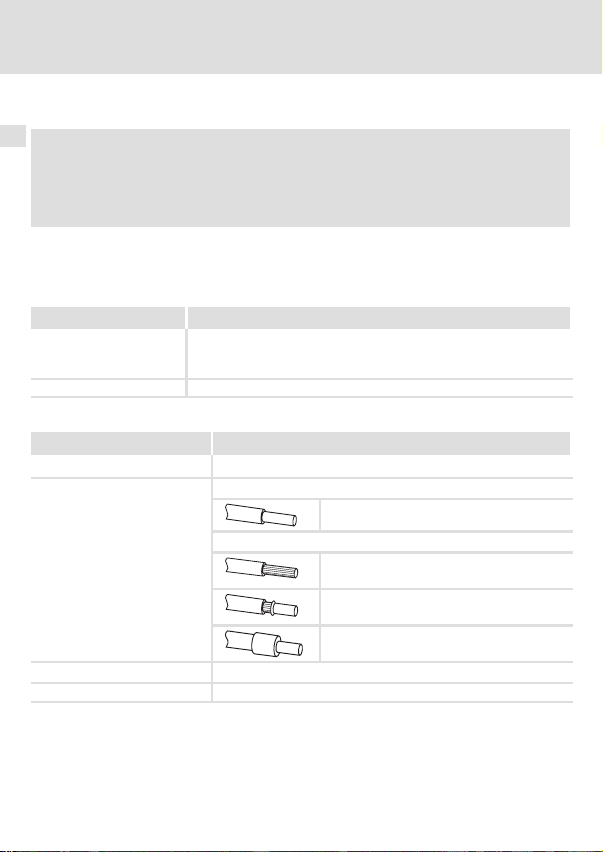
ƒ erfolgt über die 2−polige Steckerleiste mit Schraubanschluss (24 V DC).
Klemme Beschreibung
+ Externe Spannungsversorgung
− Bezugspotenzial für externe Spannungsversorgung
Daten der Anschlussklemmen
Bereich Werte
Elektrischer Anschluss Steckerleiste mit Schraubanschluss
Anschlussmöglichkeiten
Anzugsmoment 0.5 ... 0.6 Nm (4.4 ... 5.3 lb−in)
Abisolierlänge 6 mm
U = 24VDC(20.4 V − 0%... 28.8 V +0%)
I = 85 mA
starr:
flexibel:
2
1.5 mm
(AWG 16)
ohne Aderendhülse
2
(AWG 16)
1.5 mm
mit Aderendhülse, ohne Kunststoffhülse
2
(AWG 16)
1.5 mm
mit Aderendhülse, mit Kunststoffhülse
2
(AWG 16)
1.5 mm
22
l
EDK2192IB DE / EN / FR 2.0
Page 23

Inbetriebnahme
Vor dem ersten Einschalten
7 Inbetriebnahme
Vor dem ersten Einschalten
( Stop!
Bevor Sie das Grundgerät mit dem Kommunikationsmodul erstmalig
einschalten, überprüfen Sie die gesamte Verdrahtung auf Vollständigkeit,
Kurzschluss und Erdschluss.
, Kommunikationshandbuch EMF2192IB (EtherCAT)
Hier finden Sie ausführliche Informationen zur Inbetriebnahme des
Kommunikationsmoduls.
7
EDK2192IB DE / EN / FR 2.0
l
23
Page 24
8 Diagnose
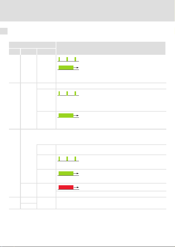
8 Diagnose
Zur Störungsdiagnose stehen für das Kommunikationsmodul die auf der Frontseite platzierten LEDs zur Verfügung.
LED
Pos. Farbe Zustand
grün
0
1
2
3
blinkt
an
grün
aus Das Kommunikationsmodul ist nicht mit Spannung versorgt.
blinkt
an
grün
Die EtherCAT−Statusmaschine steuert die zweifarbige LED (rot/grün) an:
l Statusmeldungen erscheinen in grüner Farbe.
l Fehlermeldungen erscheinen in roter Farbe.
aus Das Kommunikationsmodul ist am Feldbus nicht aktiv oder befindet
blinkt
an
rot an
rot
grün
Beschreibung
l Die EtherCAT−Verbindung ist vorhanden.
l Die Datenkommunikation der EtherCAT−Verbindung ist aktiv.
Das Kommunikationsmodul ist mit Spannung versorgt, hat aber keine
Verbindung zum Grundgerät. (Grundgerät ist ausgeschaltet, in der
Initialisierungsphase oder nicht vorhanden.)
Das Kommunikationsmodul ist mit Spannung versorgt und hat eine
Verbindung zum Grundgerät.
sich im Zustand "Init".
Zustand "Pre−Operational" oder "Safe−Operational" aktiv.
Das Kommunikationsmodul befindet sich im Zustand "Operational".
Ein Fehler liegt im Bereich des Kommunikationsmoduls vor.
Die rote und grüne Drive−LED kennzeichnet den Betriebszustand des
Grundgerätes (siehe Betriebsanleitung des Grundgerätes).
24
l
EDK2192IB DE / EN / FR 2.0
Page 25

Diagnose 8
EDK2192IB DE / EN / FR 2.0
l
25
Page 26

Legend for fold−out page
Pos. Description Detailed
LED status displays ^ 46
0
...
3
Port for the external voltage supply of the communication module
4
Type: Terminal strip with screw−type connection, 2−pin
Terminal for synchronisation of the standard device
5
Design: Terminal strip with screw−type connection, 3−pin
EtherCAT connection (OUT)
6
Type: RJ45 socket in acc. with IEC 60603−7
EtherCAT connection (IN)
7
Type: RJ45 socket in acc. with IEC 60603−7
Nameplate ^ 34
8
0Fig. 0Tab. 0
information
^ 44
^ 42
^ 39
26
l
EDK2192IB DE / EN / FR 2.0
Page 27

Contents i
1 About this documentation 28 . . . . . . . . . . . . . . . . . . . . . . . . . . . . . . . . . . . . . . . . . . . .
Conventions used 29 . . . . . . . . . . . . . . . . . . . . . . . . . . . . . . . . . . . . . . . . . . . . . . . . . . . .
Notes used 30 . . . . . . . . . . . . . . . . . . . . . . . . . . . . . . . . . . . . . . . . . . . . . . . . . . . . . . . . .
2 Safety instructions 32 . . . . . . . . . . . . . . . . . . . . . . . . . . . . . . . . . . . . . . . . . . . . . . . . . . .
3 Product description 33 . . . . . . . . . . . . . . . . . . . . . . . . . . . . . . . . . . . . . . . . . . . . . . . . . .
Function 33 . . . . . . . . . . . . . . . . . . . . . . . . . . . . . . . . . . . . . . . . . . . . . . . . . . . . . . . . . . .
Application as directed 33 . . . . . . . . . . . . . . . . . . . . . . . . . . . . . . . . . . . . . . . . . . . . . . .
Scope of supply 34 . . . . . . . . . . . . . . . . . . . . . . . . . . . . . . . . . . . . . . . . . . . . . . . . . . . . . .
Identification 34 . . . . . . . . . . . . . . . . . . . . . . . . . . . . . . . . . . . . . . . . . . . . . . . . . . . . . . .
4 Technical data 35 . . . . . . . . . . . . . . . . . . . . . . . . . . . . . . . . . . . . . . . . . . . . . . . . . . . . . . .
General data 35 . . . . . . . . . . . . . . . . . . . . . . . . . . . . . . . . . . . . . . . . . . . . . . . . . . . . . . .
Dimensions 36 . . . . . . . . . . . . . . . . . . . . . . . . . . . . . . . . . . . . . . . . . . . . . . . . . . . . . . . . .
5 Mechanical installation 37 . . . . . . . . . . . . . . . . . . . . . . . . . . . . . . . . . . . . . . . . . . . . . . .
6 Electrical installation 38 . . . . . . . . . . . . . . . . . . . . . . . . . . . . . . . . . . . . . . . . . . . . . . . . .
Wiring according to EMC 38 . . . . . . . . . . . . . . . . . . . . . . . . . . . . . . . . . . . . . . . . . . . . . .
EtherCAT connection 39 . . . . . . . . . . . . . . . . . . . . . . . . . . . . . . . . . . . . . . . . . . . . . . . . .
Synchronisation of the standard device 42 . . . . . . . . . . . . . . . . . . . . . . . . . . . . . . . . .
Internal voltage supply 43 . . . . . . . . . . . . . . . . . . . . . . . . . . . . . . . . . . . . . . . . . . . . . .
External voltage supply 44 . . . . . . . . . . . . . . . . . . . . . . . . . . . . . . . . . . . . . . . . . . . . . .
7 Commissioning 45 . . . . . . . . . . . . . . . . . . . . . . . . . . . . . . . . . . . . . . . . . . . . . . . . . . . . .
Before switching on 45 . . . . . . . . . . . . . . . . . . . . . . . . . . . . . . . . . . . . . . . . . . . . . . . . .
8 Diagnostics 46 . . . . . . . . . . . . . . . . . . . . . . . . . . . . . . . . . . . . . . . . . . . . . . . . . . . . . . . . .
EDK2192IB DE / EN / FR 2.0
l
27
Page 28

1 About this documentation
1 About this documentation
Contents
This documentation contains ...
ƒ information about the mechanical and electrical installation of the communication
module;
ƒ safety instructions that you must observe at all times;
ƒ information on versions of the Lenze standard devices to be used;
ƒ dimensions of the communication module.
EtherCAT® is a registered trademark and patented technology, licensed by Beckhoff Automation GmbH, Germany.
Validity information
The information given in this documentation is valid for the following devices:
Extension module Type designation From hardware version
EtherCAT
communication
module
Target group
This documentation is intended for persons who install and commission the described
product according to the project requirements.
EMF2192IB VA 1.0
upwards
From software version
upwards
I Tip!
Information and auxiliary devices around the Lenze products can be found in
the download area at
http://www.Lenze.com
28
l
EDK2192IB DE / EN / FR 2.0
Page 29

About this documentation
Conventions used
Conventions used
This documentation uses the following conventions to distinguish between different types
of information:
Type of information Identification Examples/notes
Numbers
Decimal separator
Symbols
Page reference
Point The decimal point is used throughout
^
this documentation.
Example: 1234.56
Reference to another page with
additional information
Example: ^ 16 = see page 16
1
EDK2192IB DE / EN / FR 2.0
l
29
Page 30

1 About this documentation
Notes used
Notes used
The following pictographs and signal words are used in this documentation to indicate
dangers and important information:
Safety instructions
Structure of safety instructions:
} Danger!
(characterises the type and severity of danger)
Note
(describes the danger and gives information about how to prevent dangerous
situations)
Pictograph and signal word Meaning
Danger of personal injury through dangerous electrical
voltage.
{ Danger!
} Danger!
( Stop!
Reference to an imminent danger that may result in
death or serious personal injury if the corresponding
measures are not taken.
Danger of personal injury through a general source of
danger.
Reference to an imminent danger that may result in
death or serious personal injury if the corresponding
measures are not taken.
Danger of property damage.
Reference to a possible danger that may result in
property damage if the corresponding measures are not
taken.
30
l
EDK2192IB DE / EN / FR 2.0
Page 31

Application notes
Pictograph and signal word Meaning
About this documentation
Notes used
1
) Note!
I Tip!
,
Important note to ensure troublefree operation
Useful tip for simple handling
Reference to another documentation
EDK2192IB DE / EN / FR 2.0
l
31
Page 32

2 Safety instructions
2 Safety instructions
} Danger!
Inappropriate handling of the communication module and the standard device
can cause serious personal injury and material damage.
Observe the safety instructions and residual hazards described in the
documentation for the standard device.
( Stop!
Electrostatic discharge
Electronic components of the communication module can be damaged or
destroyed through electrostatic discharge.
Possible consequences:
ƒ The communication module is damaged.
ƒ Fieldbus communication is not possible or faulty.
Protective measures
ƒ Discharge electrostatic charges before touching the module.
32
l
EDK2192IB DE / EN / FR 2.0
Page 33

Product description
Function
3 Product description
Function
The communication module connects Lenze devices of the series 8200 vector, 9300 and ECS
to the EtherCAT communication system.
Application as directed
The communication module ...
ƒ is a device intended for use in industrial power systems.
ƒ is only to be used in EtherCAT networks.
ƒ can be used in connection with the following standard devices (nameplate data):
Device type Design
82EVxxxxxBxxxXX
82CVxxxxxBxxxXX
82DVxxxKxBxxxXX
EPL 10200 E
33.93xx xE.
33.938X xE.
33.93xx xC.
33.93xx EI / ET
33.93xx CI / CT
ECSxSxxxx4xxxxXX
ECSxPxxxx4xxxxXX
ECSxMxxxx4xxxxXX
ECSxAxxxx4xxxxXX
ECSxExxxx4xxxxXX
1) Operating system software versions of the controllers
Version
HW SW
Vx 1x
Vx 1x
Vx 1x
1x 1x
2x 1x
1x 0x
2x 1x
2x 1x
2x 1x
1A 7.0
1A 7.0
1A 7.0
1A 7.0
VA 5.0
Any other use shall be deemed inappropriate!
Variant Explanation
1)
8200 vector
8200 vector, cold plate
8200 vector, thermally
separated
Drive PLC
Vxxx 9321 − 9332 vector
9381 − 9383 vector
Vxxx 9321 − 9332, vector with
cold plate design
Vxxx 9300 Servo PLC
Vxxx 9300 Servo PLC, cold plate
ECSxS "Speed & Torque"
ECSxP "Posi & Shaft"
ECSxM "Motion"
ECSxA "Application"
ECSxE power supply
module
3
EDK2192IB DE / EN / FR 2.0
l
33
Page 34

3 Product description
Scope of supply
Scope of supply
ƒ Communication module EMF2192IB (EtherCAT)
ƒ Mounting Instructions
I Tip!
Further information regarding this communication module can be found in
the corresponding communication manual.
The PDF file can be found in the download area at
http://www.Lenze.com
Identification
L
Type
Id.-No.
Prod.-No.
E82AF000P0B201XX
Type code
Device series
Hardware version
Software version
34
W
l
2192ECAT013
33.2192IB VA 1.0
EDK2192IB DE / EN / FR 2.0
Page 35

Technical data
General data
4 Technical data
General data
Field Values
Order designation EMF2192IB
Communication profile EtherCAT
Supported device profile
and mailbox protocol
Communication medium S/FTP (Screened Foiled Twisted Pair, ISO/IEC 11801 and EN 50173),
Interface RJ45, standard Ethernet (in accordance with IEEE 802.3), 100Base−TX (Fast
Network topology Line, switch
Node type EtherCAT slave
Number of nodes Max. 65535 (in the entire network)
Cable length between
two EtherCAT nodes
Cycle times 1 ms or an integer multiple of 1 ms,
Node type EtherCAT slave
Vendor ID 0x3B
Product ID Depending on the standard device used
Revision ID Depending on the major software version of the EtherCAT module
Baud rate 100 Mbps
Voltage supply
Conformities, approvals
CANopen over EtherCAT (CoE)
CAT 5e
Ethernet)
Max. 100 m (typical)
Max. 15 ms if "Distributed clocks" (DC) are used
External supply via separate power supply unit
l Terminal "+":
l Terminal "−":
CE
U = 24VDC(20.4 V − 0%... 28.8 V+ 0%)
I = 140 mA
Reference potential for external voltage supply
4
, Documentation for Lenze series of devices 8200 vector, 9300 and ECS
Here you can find the ambient conditions and the electromagnetic
compatibility (EMC) specifications applying to the communication module.
EDK2192IB DE / EN / FR 2.0
l
35
Page 36

4 Technical data
Dimensions
Dimensions
All dimensions in mm
2192ECAT001B
36
l
EDK2192IB DE / EN / FR 2.0
Page 37

Mechanical installation 5
5 Mechanical installation
2102LEC014
Fig. 1 Attaching the communication module
ƒ Plug the communication module onto the standard device (here: 8200 vector).
ƒ Tighten the communication module to the standard device using the fixing screw in
order to ensure a good PE connection.
) Note!
For the internal supply of the communication module by the 8200 vector
frequency inverter the jumper has to be adjusted within the interface opening
(see illustration above).
Observe the notes (^ 43).
EDK2192IB DE / EN / FR 2.0
l
37
Page 38

6 Electrical installation
Wiring according to EMC
6 Electrical installation
Wiring according to EMC
For wiring according to EMC requirements observe the following points:
) Note!
ƒ Separate control cables/data lines from motor cables.
ƒ Connect the shields of control cables/data lines at both ends in the case of
digital signals.
ƒ Use an equalizing conductor with a cross−section of at least 16mm
(reference:PE) to avoid potential differences between the bus nodes.
ƒ Observe the other notes concerning EMC−compliant wiring given in the
documentation for the standard device.
2
38
l
EDK2192IB DE / EN / FR 2.0
Page 39

Electrical installation
EtherCAT connection
EtherCAT connection
You can use a standard Ethernet patch cable for connection to the communication module
(see "Ethernet cable specifications" (^ 40)).
) Note!
Plug/remove the Ethernet cable plug vertically into/from the socket to make
sure that the RJ45 socket will not be damaged.
Pin assignment
RJ45 socket PIN Signal
1 Tx +
2 Tx −
3 Rx +
4 −
5 −
6 Rx −
7 −
E94AYCXX004C
8 −
I Tip!
The EtherCAT interfaces are equipped with an auto−MDIX function. This
function adapts the polarity of the RJ45 interfaces such that independently of
the polarity of the opposite EtherCAT interface and the cable type used
(standard patch cable or crossover cable) a connection is established.
6
EDK2192IB DE / EN / FR 2.0
l
39
Page 40

6 Electrical installation
EtherCAT connection
Ethernet cable specifications
) Note!
Only use cables complying with the below specifications.
Specification of the Ethernet cable
Ethernet standard Standard Ethernet (in accordance with IEEE 802.3), 100Base−TX
Cable type S/FTP (Screened Foiled Twisted Pair, ISO/IEC 11801 or EN 50173),
Damping 23.2 dB (at 100 MHz and per 100 m)
Crosstalk damping 24 dB (at 100 MHz and per 100 m)
Return loss 10 dB (per 100 m)
Surge impedance
(Fast Ethernet)
CAT 5e
100
40
l
EDK2192IB DE / EN / FR 2.0
Page 41

Electrical installation
EtherCAT connection
Colour code of Ethernet cable
) Note!
Wiring and colour code are standardised in EIA/TIA 568A/568B.
You can use 4−pin Ethernet cables in accordance with the industrial standard.
The cable type only connects the assigned pins 1, 2, 3 and 6 with each other.
Fig. 2 Ethernet plug in accordance with EIA/TIA 568A/568B
Pair Pin Signal EIA/TIA 568A EIA/TIA 568B
1
3
2 3 Rx + White/orange White/green
1
2 6 Rx − Orange Green
4
Tx + White/green White/orange
2 Tx − Green Orange
4 Not assigned Blue Blue
5 Not assigned White/blue Blue/white
7 Not assigned White/brown White/brown
8 Not assigned Brown Brown
6
E94YCEI004A
EDK2192IB DE / EN / FR 2.0
l
41
Page 42

6 Electrical installation
Synchronisation of the standard device
Synchronisation of the standard device
The synchronisation of the standard device via the EtherCAT fieldbus ˘ if it is supported ˘
can be carried out via the 3−pin plug connector with screw connection (sync).
) Note!
ECS servo system
ƒ For the ECS axis modules, a synchronisation with operating system
software version 8.3 is possible.
ƒ For the ECS power supply module a synchronisation is not supported.
Wire ...
ƒ terminal "0" to the corresponding sync input of the standard device (see
documentation of the standard device).
ƒ the sync supply to the 24V supply of the communication module or the standard
device.
EtherCAT-
Sync
Terminal Description
+ External sync supply (SELV/PELV)
0 Sync output
− Reference potential for external sync supply
42
W
Opto
U = 24VDC(20.4 V − 0%... 28.8 V +0%)
(t = 150
s, I
max
0
= 10 mA at 24 V)
l
2192ECAT002
EDK2192IB DE / EN / FR 2.0
Page 43

Electrical installation
Internal voltage supply
Internal voltage supply
) Note!
Internal voltage supply has been selected in the case of standard devices with
an extended AIF interface opening (e.g. front of 8200 vector). The area shown
on a grey background in the graphic marks the jumper position.
ƒ By default, this is not supplied internally in the standard device.
ƒ For internal voltage supply place the jumper on the position indicated
below.
In the case of all other device series (9300, ECS), voltage is always supplied
from the standard device.
6
(Only external voltage supply possible.)
EDK2192IB DE / EN / FR 2.0
Lenze setting
l
Internal voltage supply
43
Page 44
6 Electrical installation
External voltage supply
External voltage supply
) Note!
Always use a separate power supply unit in every control cabinet and safely
separate it according to EN 61800−5−1 ("SELV"/"PELV") in the case of external
voltage supply and larger distances between the control cabinets.
The external voltage supply ...
ƒ is necessary if EtherCAT communication is to be maintained when the standard
device is switched off.
ƒ is provided via the 2−pin terminal strip with screw−type connection (24 V DC).
Terminal Description
+ External voltage supply
− Reference potential for external voltage supply
Terminal data
Area Values
Electrical connection Plug connector with screw connection
Possible connections
Tightening torque 0.5 ... 0.6 Nm (4.4 ... 5.3 lb−in)
Stripping length 6 mm
U = 24 V DC(20.4 V − 0%... 28.8 V +0%)
I = 85 mA
rigid:
flexible:
2
1.5 mm
(AWG 16)
without wire end ferrule
2
(AWG 16)
1.5 mm
with wire end ferrule, without plastic sleeve
2
1.5 mm
(AWG 16)
with wire end ferrule, with plastic sleeve
2
(AWG 16)
1.5 mm
44
l
EDK2192IB DE / EN / FR 2.0
Page 45

Commissioning
Before switching on
7 Commissioning
Before switching on
( Stop!
Before switching on the standard device with the communication module for
the first time, check the entire wiring for completeness, short circuit and earth
fault.
, Communication manual EMF2192IB (EtherCAT)
Here you can find detailed information on the commissioning of the
communication module.
7
EDK2192IB DE / EN / FR 2.0
l
45
Page 46

8 Diagnostics
8 Diagnostics
The LEDs on the front are provided to the communication module for the purpose of fault
diagnostics.
LED
Pos. Colour Status
green
0
1
2
3
blinking
on
green
off The communication module is not supplied with voltage.
blinking
on
green
The EtherCAT state machine controls the two−colored LED (red/green):
l Status messages are shown in green.
l Error messages are shown in red.
off The communication module is not active on the fieldbus or is in the
blinking
on
red on
red
green
Description
l The EtherCAT connection has been established.
l Data communication of the EtherCAT connection is active.
The communication module is supplied with voltage, but has no
connection to the standard device (standard device is switched off, in
the initialisation phase, or not available.)
The communication module is supplied with voltage and is connected
to the standard device.
"Init" status.
"Pre−operational" or "Safe−operational" state active.
The communication module is in the "Operational" status.
An error has occurred in the communication module.
The red and green drive LED indicates the operating status of the
standard device (see operating instructions of the standard device).
46
l
EDK2192IB DE / EN / FR 2.0
Page 47

Diagnostics 8
EDK2192IB DE / EN / FR 2.0
l
47
Page 48

Légende de l’illustration de la page dépliante
Pos. Description Informations
Affichages d’état par LED ^ 68
0
...
3
Raccordement de l’alimentation externe du module de communication
4
Version : bornier avec fixation par vis, à 2 bornes
Raccordement pour la synchronisation de l’appareil de base
5
Version : bornier avec fixation par vis, à 3 bornes
Raccordement EtherCAT (OUT)
6
Version : prise RJ45 selon CEI 60603−7
Raccordement EtherCAT (IN)
7
Version : prise RJ45 selon CEI 60603−7
Plaque signalétique ^ 56
8
0Fig. 0Tab. 0
détaillées
^ 66
^ 64
^ 61
48
l
EDK2192IB DE / EN / FR 2.0
Page 49

Sommaire i
1 Présentation du document 50 . . . . . . . . . . . . . . . . . . . . . . . . . . . . . . . . . . . . . . . . . . . .
Conventions utilisées 51 . . . . . . . . . . . . . . . . . . . . . . . . . . . . . . . . . . . . . . . . . . . . . . . . .
Consignes utilisées 52 . . . . . . . . . . . . . . . . . . . . . . . . . . . . . . . . . . . . . . . . . . . . . . . . . . .
2 Consignes de sécurité 54 . . . . . . . . . . . . . . . . . . . . . . . . . . . . . . . . . . . . . . . . . . . . . . . .
3 Description du produit 55 . . . . . . . . . . . . . . . . . . . . . . . . . . . . . . . . . . . . . . . . . . . . . . . .
Fonction 55 . . . . . . . . . . . . . . . . . . . . . . . . . . . . . . . . . . . . . . . . . . . . . . . . . . . . . . . . . . .
Utilisation conforme à la fonction 55 . . . . . . . . . . . . . . . . . . . . . . . . . . . . . . . . . . . . . .
Equipement livré 56 . . . . . . . . . . . . . . . . . . . . . . . . . . . . . . . . . . . . . . . . . . . . . . . . . . . .
Identification 56 . . . . . . . . . . . . . . . . . . . . . . . . . . . . . . . . . . . . . . . . . . . . . . . . . . . . . . .
4 Spécifications techniques 57 . . . . . . . . . . . . . . . . . . . . . . . . . . . . . . . . . . . . . . . . . . . . .
Caractéristiques générales 57 . . . . . . . . . . . . . . . . . . . . . . . . . . . . . . . . . . . . . . . . . . . .
Encombrements 58 . . . . . . . . . . . . . . . . . . . . . . . . . . . . . . . . . . . . . . . . . . . . . . . . . . . . .
5 Installation mécanique 59 . . . . . . . . . . . . . . . . . . . . . . . . . . . . . . . . . . . . . . . . . . . . . . .
6 Installation électrique 60 . . . . . . . . . . . . . . . . . . . . . . . . . . . . . . . . . . . . . . . . . . . . . . . .
Câblage conforme CEM 60 . . . . . . . . . . . . . . . . . . . . . . . . . . . . . . . . . . . . . . . . . . . . . . .
Raccordement EtherCAT 61 . . . . . . . . . . . . . . . . . . . . . . . . . . . . . . . . . . . . . . . . . . . . . .
Synchronisation de l’appareil de base 64 . . . . . . . . . . . . . . . . . . . . . . . . . . . . . . . . . .
Alimentation interne 65 . . . . . . . . . . . . . . . . . . . . . . . . . . . . . . . . . . . . . . . . . . . . . . . .
Alimentation externe 66 . . . . . . . . . . . . . . . . . . . . . . . . . . . . . . . . . . . . . . . . . . . . . . . .
7 Mise en service 67 . . . . . . . . . . . . . . . . . . . . . . . . . . . . . . . . . . . . . . . . . . . . . . . . . . . . . .
Avant la première mise sous tension 67 . . . . . . . . . . . . . . . . . . . . . . . . . . . . . . . . . . . .
8 Diagnostic 68 . . . . . . . . . . . . . . . . . . . . . . . . . . . . . . . . . . . . . . . . . . . . . . . . . . . . . . . . . .
EDK2192IB DE / EN / FR 2.0
l
49
Page 50

1 Présentation du document
1 Présentation du document
Contenu
Le présent document contient ...
ƒ des informations sur l’installation mécanique et électrique du module de
communication ;
ƒ des consignes de sécurité à respecter impérativement ;
ƒ des renseignements sur les versions des appareils de base Lenze à utiliser ;
ƒ les dimensions du module de communication.
EtherCAT® est une marque déposée et une technologie brevetée sous licence de Beckhoff
Automation GmbH, Allemagne.
Validité
Les informations contenues dans le présent document s’appliquent aux appareils suivants :
Module d’extension Référence de
Module de
communication EtherCAT
Public visé
Ce document est destiné aux personnes chargées d’installer et de mettre en service le
produit décrit selon les exigences du projet.
commande
EMF2192IB VA 1.0
A partir de la version
matérielle
A partir de la version
logicielle
I Conseil !
Toutes les informations relatives aux produits Lenze peuvent être téléchargées
sur notre site à l’adresse suivante :
http://www.Lenze.com
50
l
EDK2192IB DE / EN / FR 2.0
Page 51

Présentation du document
Conventions utilisées
Conventions utilisées
Pour faire la distinction entre différents types d’informations, ce document utilise les
conventions suivantes :
Type d’information Marquage Exemples/remarques
Représentation des chiffres
Séparateur décimal
Symboles
Renvoi à une page
Point Le point décimal est généralement
^
utilisé.
Exemple : 1234.56
Renvoi à une autre page présentant
des informations supplémentaires
Exemple : ^ 16 = voir page 16
1
EDK2192IB DE / EN / FR 2.0
l
51
Page 52

1 Présentation du document
Consignes utilisées
Consignes utilisées
Pour indiquer des risques et des informations importantes, la présente documentation
utilise les mots et symboles suivants :
Consignes de sécurité
Présentation des consignes de sécurité
} Danger !
(Le pictogramme indique le type de risque.)
Explication
(L’explication décrit le risque et les moyens de l’éviter.)
Pictogramme et mot associé Explication
Situation dangereuse pour les personnes en raison d’une
tension électrique élevée
{ Danger !
} Danger !
( Stop !
Indication d’un danger imminent qui peut avoir pour
conséquences des blessures mortelles ou très graves en
cas de non−respect des consignes de sécurité
correspondantes
Situation dangereuse pour les personnes en raison d’un
danger d’ordre général
Indication d’un danger imminent qui peut avoir pour
conséquences des blessures mortelles ou très graves en
cas de non−respect des consignes de sécurité
correspondantes
Risques de dégâts matériels
Indication d’un risque potentiel qui peut avoir pour
conséquences des dégâts matériels en cas de non−respect
des consignes de sécurité correspondantes
52
l
EDK2192IB DE / EN / FR 2.0
Page 53

Consignes d’utilisation
Pictogramme et mot associé Explication
Présentation du document
Consignes utilisées
1
) Remarque
importante !
I Conseil !
,
Remarque importante pour assurer un fonctionnement
correct
Conseil utile pour faciliter la mise en uvre
Référence à une autre documentation
EDK2192IB DE / EN / FR 2.0
l
53
Page 54

2 Consignes de sécurité
2 Consignes de sécurité
} Danger !
Toute utilisation non conforme à la fonction du module de communication et
de l’appareil de base risque d’entraîner des blessures graves et des dommages
matériels.
Tenir compte des consignes de sécurité et des dangers résiduels indiqués dans
la documentation de l’appareil de base.
( Stop !
Décharge électrostatique
Des composants électroniques à l’intérieur du module de communication
peuvent être endommagés ou détruits par des décharges électrostatiques.
Risques encourus :
ƒ Le module de communication est endommagé.
ƒ La communication par bus de terrain est impossible ou erronée.
Mesures de protection
ƒ Avant tout contact avec le module, se libérer des charges électrostatiques.
54
l
EDK2192IB DE / EN / FR 2.0
Page 55

Description du produit
Fonction
3 Description du produit
Fonction
Le module de communication relie les appareils Lenze des séries 8200 vector, 9300 et ECS
au système de communication EtherCAT.
Utilisation conforme à la fonction
Le module de communication...
ƒ est un équipement de production destiné à être utilisé dans des installations
industrielles à courant fort ;
ƒ ne doit être utilisé que dans des réseaux EtherCAT.
ƒ est compatible avec les appareils de base ci−dessous (voir plaque signalétique) :
Type d’appareil Version
82EVxxxxxBxxxXX
82CVxxxxxBxxxXX
82DVxxxKxBxxxXX
EPL 10200 E
33.93XX xE.
33.938x xE.
33.93XX xC.
33.93XX EI / ET
33.93XX CI / CT
ECSxSxxxx4xxxxXX
ECSxPxxxx4xxxxXX
ECSxMxxxx4xxxxXX
ECSxAxxxx4xxxxXX
ECSxExxxx4xxxxXX
1) Version logicielle du système d’exploitation des variateurs
Toute autre utilisation est contre−indiquée !
Version
HW SW
Vx 1x
Vx 1x
Vx 1x
1x 1x
2x 1x
1x 0x
2x 1x
2x 1x
2x 1x
1A 7.0
1A 7.0
1A 7.0
1A 7.0
VA 5.0
Variante Précisions
1)
8200 vector
8200 vector, montage sur
semelle de
refroidissement
8200 vector, séparation
thermique
Drive PLC
Vxxx 9321 − 9332 vector
9381 − 9383 vector
Vxxx 9321 − 9332, vector avec
montage sur semelle de
refroidissement
Vxxx 9300 Servo PLC
Vxxx 9300 Servo PLC, montage
sur semelle de
refroidissement
ECSxS "Speed & Torque"
ECSxP "Posi & Shaft"
ECSxM "Motion"
ECSxA "Application"
Module d’alimentation
ECSxE
3
EDK2192IB DE / EN / FR 2.0
l
55
Page 56

3 Description du produit
Equipement livré
Equipement livré
ƒ Module de communication EMF2192IB (EtherCAT)
ƒ Instructions de montage
I Conseil !
Pour plus d’informations sur le module de communication, consulter le
manuel de communication correspondant.
Le fichier au format PDF peut être téléchargé à l’adresse suivante :
http://www.Lenze.com
Identification
L
Type
Id.-No.
Prod.-No.
E82AF000P0B201XX
Codification des types
Série d’appareils
Version matérielle
Version logicielle
56
W
l
2192ECAT013
33.2192IB VA 1.0
EDK2192IB DE / EN / FR 2.0
Page 57

Spécifications techniques
Caractéristiques générales
4 Spécifications techniques
Caractéristiques générales
Caractéristique Spécifications
Référence de commande EMF2192IB
Profil de communication EtherCAT
Profil d’appareil pris en
charge et protocole de
messagerie
Support de
communication
Interface RJ45, Standard Ethernet (selon IEEE 802.3), 100Base−TX (Fast Ethernet)
Topologie du réseau Ligne, switch
Type de participant Esclave EtherCAT
Nombre de participants 65535 max. (sur l’ensemble du réseau)
Longueur de câble entre
deux participants
EtherCAT
Temps de cycle 1 ms ou un multiple entier de 1 ms,
Type de participant Esclave EtherCAT
Vendor−ID 0x3B
Product−ID Dépend de l’appareil de base utilisé
Revision−ID Dépend de la version principale du logiciel du module EtherCAT
Vitesse de transmission 100 Mbits/s
Alimentation
Conformités,
homologations
CANopen over EtherCAT (CoE)
S/FTP (Screened Foiled Twisted Pair, ISO/CEI 11801 ou EN 50173), CAT 5e
100 m max. (cas général)
15 ms max. avec horloges distribuées (fonction "Distributed clocks", DC)
Alimentation externe via bloc d’alimentation séparé
l Borne "+":
l Borne "−":
CE
U = 24VCC(20.4 V − 0%... 28.8 V+ 0%)
I = 140 mA
Potentiel de référence pour alimentation externe
4
, Documentations relatives aux séries d’appareils Lenze 8200 vector,
9300 et ECS
Ces documentations décrivent les conditions ambiantes et les données de
compatibilité électromagnétique (CEM) également valables pour le module de
communication.
EDK2192IB DE / EN / FR 2.0
l
57
Page 58

4 Spécifications techniques
Encombrements
Encombrements
Toutes les cotes en mm
2192ECAT001B
58
l
EDK2192IB DE / EN / FR 2.0
Page 59

Installation mécanique 5
5 Installation mécanique
2102LEC014
Fig. 1 Brancher le module de communication
ƒ Enficher le module de communication dans l’appareil de base (ici : 8200 vector).
ƒ Visser le module de communication sur l’appareil de base à l’aide de la vis de fixation
pour assurer une bonne liaison avec la terre.
) Remarque importante !
Pour l’alimentation interne du module de communication par le convertisseur
de fréquence 8200 vector, le cavalier doit être inséré dans l’ouverture prévue à
cet effet (voir schéma ci−dessus).
Voir également les remarques (^ 65).
EDK2192IB DE / EN / FR 2.0
l
59
Page 60

6 Installation électrique
Câblage conforme CEM
6 Installation électrique
Câblage conforme CEM
Pour s’assurer que le câblage est conforme aux exigences à respecter en matière de CEM,
vérifier les points suivants :
) Remarque importante !
ƒ Séparer physiquement les câbles de commande/de données des câbles
moteur.
ƒ Pour les signaux numériques, blinder les câbles de commande et de
données aux deux extrémités.
ƒ Pour éviter les différences de potentiel entre les participants au bus, utiliser
une ligne de compensation d’une section minimale de 16mm
PE).
ƒ Respecter les autres consignes relatives à un câblage conforme CEM
fournies dans la documentation de l’appareil de base.
2
(référence :
60
l
EDK2192IB DE / EN / FR 2.0
Page 61

Installation électrique
Raccordement EtherCAT
Raccordement EtherCAT
Le module de communication peut être raccordé à l’aide d’un câble droit Ethernet standard
en vente dans le commerce (voir "Spécifications du câble Ethernet" (^ 62)).
) Remarque importante !
Enficher ou retirer le connecteur du câble Ethernet verticalement afin d’éviter
tout endommagement de la prise RJ45.
Affectation des broches
Prise RJ45 Broche Signal
1 Tx +
2 Tx −
3 Rx +
4 −
5 −
6 Rx −
7 −
E94AYCXX004C
8 −
I Conseil !
Les interfaces EtherCAT sont dotées d’une fonction Auto−MDIX. Celle−ci permet
d’adapter l’affectation des broches des prises RJ45 de manière à pouvoir établir
une liaison indépendamment de l’affectation des broches de l’autre interface
EtherCAT raccordée et du type de câble utilisé (câble droit standard ou câble
croisé).
6
EDK2192IB DE / EN / FR 2.0
l
61
Page 62

6 Installation électrique
Raccordement EtherCAT
Spécifications du câble Ethernet
) Remarque importante !
Utiliser exclusivement des câbles conformes aux spécifications indiquées.
Spécifications du câble Ethernet
Standard Ethernet Standard Ethernet (selon IEEE 802.3), 100Base−TX (Fast Ethernet)
Type de câble S/FTP (Screened Foiled Twisted Pair, ISO/CEI 11801 ou EN 50173),
Amortissement 23.2 dB (pour 100 MHz et par segment de 100 m)
Affaiblissement diaphonique 24 dB (pour 100 MHz et par segment de 100 m)
Affaiblissement de régularité 10 dB (par segment de 100 m)
Impédance caractéristique
CAT 5e
100
62
l
EDK2192IB DE / EN / FR 2.0
Page 63

Installation électrique
Raccordement EtherCAT
Codification des couleurs du câble Ethernet
) Remarque importante !
Le câblage et la codification des couleurs sont définis par les normes EIA/TIA
568A/568B.
L’utilisation d’un câble Ethernet à 4 paires de fils conforme à la norme
industrielle est autorisée. Ce type de câble relie uniquement les broches
affectées 1, 2, 3 et 6.
Fig. 2 Connecteur Ethernet selon EIA/TIA 568A/568B
Paire Broche Signal EIA/TIA 568A EIA/TIA 568B
1
3
2 3 Rx + blanc/orange blanc/vert
1
2 6 Rx − orange vert
4
Tx + blanc/vert blanc/orange
2 Tx − vert orange
4 non affectée bleu bleu
5 non affectée blanc/bleu bleu/blanc
7 non affectée blanc/brun blanc/brun
8 non affectée brun brun
6
E94YCEI004A
EDK2192IB DE / EN / FR 2.0
l
63
Page 64

6 Installation électrique
Synchronisation de l’appareil de base
Synchronisation de l’appareil de base
La synchronisation de l’appareil de base via le bus de terrain EtherCAT ˘ si elle est prise en
charge ˘ peut s’effectuer par l’intermédiaire du bornier avec fixation par vis à 3 bornes
(Sync).
) Remarque importante !
Système servo ECS
ƒ Les modules d’axe ECS permettent une synchronisation avec le système
d’exploitation de la version 8.3.
ƒ Le module d’alimentation ECS ne prend pas en charge la synchronisation.
Procéder aux câblages suivants :
ƒ Raccordement de la borne "0" à l’entrée Sync correspondante de l’appareil de base
(voir la documentation afférente)
ƒ Raccordement de l’alimentation Sync avec l’alimentation 24 V du module de
communication ou de l’appareil de base
EtherCAT-
Sync
Borne Description
+ Alimentation Sync externe (SELV/PELV)
0 Sortie Sync
− Potentiel de référence de l’alimentation Sync externe
64
W
Opto
U = 24VCC(20.4 V − 0%... 28.8 V +0%)
(t = 150
s, I
= 10 mA pour 24 V)
max
0
l
2192ECAT002
EDK2192IB DE / EN / FR 2.0
Page 65

Installation électrique
Alimentation interne
Alimentation interne
) Remarque importante !
Les appareils de base dotés d’une interface AIF étendue (face avant du 8200
vector par exemple) offrent la possibilité d’une alimentation interne. Sur
l’illustration, la partie grisée désigne la position du cavalier.
ƒ A la livraison de l’appareil de base, une alimentation interne du module de
communication n’est pas prévue.
ƒ Pour activer l’alimentation interne, positionner le cavalier comme indiqué
ci−dessous.
Pour toutes les autres séries d’appareil (9300, ECS), une alimentation depuis
l’appareil de base est toujours disponible.
6
Etat à la livraison
(alimentation externe uniquement)
EDK2192IB DE / EN / FR 2.0
l
Alimentation interne
65
Page 66

6 Installation électrique
Alimentation externe
Alimentation externe
) Remarque importante !
En cas d’alimentation externe et d’écarts importants entre les armoires
électriques, utiliser impérativement dans chacune d’elles un bloc
d’alimentation avec coupure de sécurité ("SELV"/"PELV") séparé et conforme à
la norme EN 61800−5−1.
L’alimentation externe ...
ƒ est nécessaire pour maintenir la communication EtherCAT lorsque l’appareil de base
est coupé du réseau.
ƒ s’effectue via le bornier avec fixation par vis à 2 bornes (24 V CC).
Borne Description
+ Alimentation externe
− Potentiel de référence pour l’alimentation externe
Spécifications pour bornier de raccordement
Domaine Valeurs
Raccordement électrique Bornier à vis
Possibilités de raccordement
Couple de serrage 0.5... 0.6 Nm (4.4 ... 5.3 lb−in)
Longueur du fil dénudé 6 mm
U = 24VCC(20.4 V − 0%... 28.8 V +0%)
I = 85 mA
Fixe :
Souple :
2
1.5 mm
(AWG 16)
sans embout
2
(AWG 16)
1.5 mm
avec embout, sans cosse en plastique
2
(AWG 16)
1.5 mm
avec embout et cosse en plastique
2
(AWG 16)
1.5 mm
66
l
EDK2192IB DE / EN / FR 2.0
Page 67

Avant la première mise sous tension
7 Mise en service
Avant la première mise sous tension
( Stop !
Mise en service
Avant la première mise sous tension de l’appareil de base avec le module de
communication, vérifier si le câblage a été correctement réalisé dans son
intégralité et rechercher d’éventuels courts−circuits (à la terre).
, Manuel de communication EMF2192IB (EtherCAT)
Ce manuel contient des informations détaillées sur la mise en service du
module de communication.
7
EDK2192IB DE / EN / FR 2.0
l
67
Page 68

8 Diagnostic
8 Diagnostic
Les LED situées sur la face avant permettent d’effectuer le diagnostic des défauts du module
de communication.
LED
Pos. Couleur Etat
LED
0
1
2
3
Clignote
verte
ON
LED
OFF Le module de communication n’est pas alimenté.
verte
Clignote
ON
LED
La LED de deux couleurs (rouge/verte) est pilotée par l’état de la machine EtherCAT.
verte
l Les messages d’état sont affichés en vert.
l Les messages d’erreur sont affichés en rouge.
OFF Le module de communication n’est pas activé sur le bus de terrain ou
Clignote
ON
LED
ON
rouge
LED
rouge
LED
verte
Description
l La liaison EtherCAT est établie.
l La communication des données via la liaison EtherCAT est en
cours.
Le module de communication est sous tension, mais aucune liaison
n’est établie avec l’appareil de base (appareil de base hors tension, en
cours d’initialisation ou non raccordé).
Le module de communication est sous tension et la liaison avec
l’appareil de base est établie.
se trouve à l’état Init.
Etat "Pre−Operational" ou "Safe−Operational" activé
Le module de communication se trouve à l’état "Operational".
Une erreur est survenue au niveau du module de communication.
La LED Drive rouge et verte indique l’état de fonctionnement de
l’appareil de base (voir les instructions de mise en service de l’appareil
de base)
68
l
EDK2192IB DE / EN / FR 2.0
Page 69

Diagnostic 8
EDK2192IB DE / EN / FR 2.0
l
69
Page 70

© 03/2011
Lenze Automation GmbH
F
Hans−Lenze−Str. 1
D−31855 Aerzen
Germany
(
+49(0)51 54 /82−0
Ê
+49(0)51 54 /82 − 28 00
Lenze@Lenze.de
ü
www.Lenze.com
Q
Service Lenze Service GmbH
Breslauer Straße 3
D−32699 Extertal
Germany
(
008000/ 2446877 (24 h helpline)
Ê
+49(0)5154/ 82−11 12
Service@Lenze.de
EDK2192IB § .F>5 § DE / EN / FR § 2.0 § TD17
10987654321
 Loading...