

Page 1
EDK2191DB
.Ma+
L−force Communication
Montageanleitung
Mounting Instructions
Instructions de montage
POWERLINK
Ä.Ma+ä
EMF2191IB
Kommunikationsmodul
Communication module
Module de communication
Page 2

Lesen Sie zuerst diese Anleitung, bevor Sie mit den Arbeiten beginnen!
Beachten Sie die enthaltenen Sicherheitshinweise.
Please read these instructions before you start working!
Follow the enclosed safety instructions.
Veuillez lire attentivement cette documentation avant toute action !
Les consignes de sécurité doivent impérativement être respectées.
Page 3
2191EPL001B
Page 4

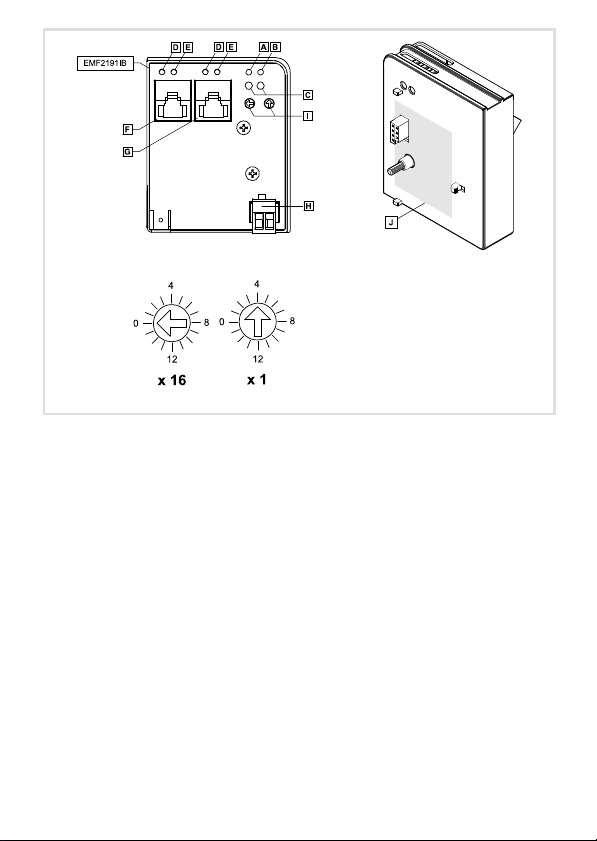
Anzeigen
Pos. Beschreibung
LED−Statusanzeigen zur Diagnose
...
Anschlüsse
Pos. Beschreibung
POWERLINK−Anschluss
Ausführung: RJ45−Buchse nach IEC 60603−7
Anschluss zur externen Versorgung des Kommunikationsmoduls
Ausführung: Steckerleiste mit Schraubanschluss, 2−polig
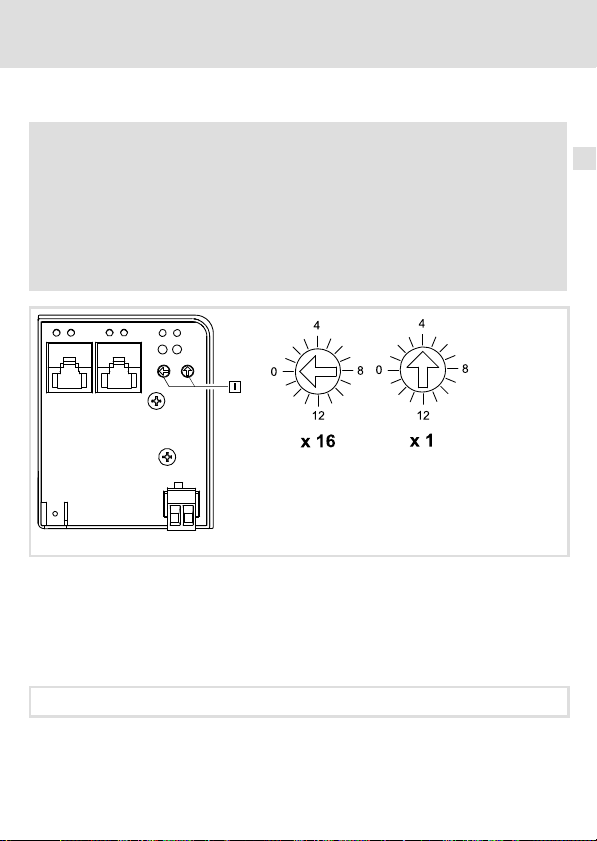
Schalter
Pos. Beschreibung
Schalter zur Adressierung des Teilnehmers
l Linker Schalter: Einstellung mit Faktor 16
l Rechter Schalter: Einstellung mit Faktor 1
Die Addition beider Produkte ergibt die Adresse (Node ID) des Teilnehmers
Node ID = 254 (die Node ID wird von einem DHCP−Server bezogen)
0Abb. 0Tab. 0
4
EDK2191DB DE/EN/FR 2.0
Page 5

Inhalt i
1 Über diese Dokumentation 6. . . . . . . . . . . . . . . . . . . . . . . . . . . . . . . . . . . . . . . . . . . .
2 Sicherheitshinweise 7. . . . . . . . . . . . . . . . . . . . . . . . . . . . . . . . . . . . . . . . . . . . . . . . . .
3 Produktbeschreibung 8. . . . . . . . . . . . . . . . . . . . . . . . . . . . . . . . . . . . . . . . . . . . . . . .
Funktion 8. . . . . . . . . . . . . . . . . . . . . . . . . . . . . . . . . . . . . . . . . . . . . . . . . . . . . . . . . . .
Bestimmungsgemäße Verwendung 8. . . . . . . . . . . . . . . . . . . . . . . . . . . . . . . . . . . .
Lieferumfang 9. . . . . . . . . . . . . . . . . . . . . . . . . . . . . . . . . . . . . . . . . . . . . . . . . . . . . . .
Identifikation 9. . . . . . . . . . . . . . . . . . . . . . . . . . . . . . . . . . . . . . . . . . . . . . . . . . . . . . .
4 Technische Daten 10. . . . . . . . . . . . . . . . . . . . . . . . . . . . . . . . . . . . . . . . . . . . . . . . . . . .
Allgemeine Daten 10. . . . . . . . . . . . . . . . . . . . . . . . . . . . . . . . . . . . . . . . . . . . . . . . . . .
Abmessungen 11. . . . . . . . . . . . . . . . . . . . . . . . . . . . . . . . . . . . . . . . . . . . . . . . . . . . . . .
5 Mechanische Installation 12. . . . . . . . . . . . . . . . . . . . . . . . . . . . . . . . . . . . . . . . . . . . .
6 Elektrische Installation 13. . . . . . . . . . . . . . . . . . . . . . . . . . . . . . . . . . . . . . . . . . . . . . .
EMV−gerechte Verdrahtung 13. . . . . . . . . . . . . . . . . . . . . . . . . . . . . . . . . . . . . . . . . . .
POWERLINK−Anschluss 14. . . . . . . . . . . . . . . . . . . . . . . . . . . . . . . . . . . . . . . . . . . . . . .
Spannungsversorgung 16. . . . . . . . . . . . . . . . . . . . . . . . . . . . . . . . . . . . . . . . . . . . . . .
7 Inbetriebnahme 18. . . . . . . . . . . . . . . . . . . . . . . . . . . . . . . . . . . . . . . . . . . . . . . . . . . . .
Vor dem ersten Einschalten 18. . . . . . . . . . . . . . . . . . . . . . . . . . . . . . . . . . . . . . . . . . .
Teilnehmeradresse einstellen 19. . . . . . . . . . . . . . . . . . . . . . . . . . . . . . . . . . . . . . . . .
8 Diagnose 20. . . . . . . . . . . . . . . . . . . . . . . . . . . . . . . . . . . . . . . . . . . . . . . . . . . . . . . . . . .
EDK2191DB DE/EN/FR 2.0
5
Page 6

1 Über diese Dokumentation
1 Über diese Dokumentation
Inhalt
Diese Dokumentation enthält ...
ƒ Informationen zur mechanischen und elektrischen Installation des
Kommunikationsmoduls;
ƒ Sicherheitshinweise, die Sie unbedingt beachten müssen;
ƒ Angaben über Versionsstände der zu verwendenden Lenze Grundgeräte;
ƒ Technische Daten des Kommunikationsmoduls;
ƒ Beschreibungen der LED−Statusanzeigen zur Diagnose.
Tipp!
Weiterführende Informationen zu diesem Kommunikationsmodul finden Sie
im entsprechenden Kommunikationshandbuch.
Die PDF−Datei finden Sie im Download−Bereich unter
http://www.Lenze.com
Informationen zur Gültigkeit
Die Informationen in dieser Dokumentation sind gültig für folgende Geräte:
Erweiterungsmodul Typenbezeichnung ab Hardwarestand ab Softwarestand
Kommunikationsmodul
POWERLINK
Zielgruppe
Diese Dokumentation wendet sich an Personen, die das beschriebene Produkt nach Projektvorgabe installieren und in Betrieb nehmen.
EMF2191IB VA 1.0
Tipp!
Informationen und Hilfsmittel rund um die Lenze−Produkte finden Sie im
Download−Bereich unter
http://www.Lenze.com
6
EDK2191DB DE/EN/FR 2.0
Page 7

Sicherheitshinweise 2
2 Sicherheitshinweise
Stop!
Elektrostatische Entladung
Durch elektrostatische Entladung können elektronische Bauteile innerhalb des
Kommunikationsmoduls beschädigt oder zerstört werden.
Mögliche Folgen:
ƒ Das Kommunikationsmodul ist defekt.
ƒ Die Feldbus−Kommunikation ist nicht möglich oder fehlerhaft.
Schutzmaßnahmen
ƒ Befreien Sie sich vor dem Berühren des Moduls von elektrostatischen
Aufladungen.
ƒ Während des Betriebs muss das Kommunikationsmodul fest mit dem Grundgerät
verbunden sein.
ƒ Verwenden Sie bei externer Spannungsversorgung in jedem Schaltschrank immer ein
separates und nach EN 61800−5−1 sicher getrenntes Netzteil (SELV/PELV).
ƒ Verwenden Sie ausschließlich Kabel, die den aufgeführten Spezifikationen (15)
entsprechen.
Dokumentation zu Grundgerät, Steuerungssystem, Anlage/Maschine
Ergreifen Sie zusätzlich alle Maßnahmen, die in diesen Dokumentationen
vorgeschrieben werden. Beachten Sie die enthaltenen Sicherheits− und
Anwendungshinweise.
EDK2191DB DE/EN/FR 2.0
7
Page 8

3 Produktbeschreibung
Funktion
3 Produktbeschreibung
Funktion
Das Kommunikationsmodul koppelt Lenze−Antriebsregler an das Kommunikationssystem
Ethernet POWERLINK.
Bestimmungsgemäße Verwendung
Das Kommunikationsmodul ...
ƒ ist ein Betriebsmittel zum Einsatz in industriellen Starkstromanlagen;
ƒ nur in POWERLINK−Netzwerken einsetzen;
ƒ ist einsetzbar in Verbindung mit folgenden Grundgeräten
(Typenschildbezeichnungen):
Gerätetyp Ausführung
82EVxxxxxBxxxXX
82CVxxxxxBxxxXX
82DVxxxKxBxxxXX
EPL 10200 E
33.93XX xE.
33.938X xE.
33.93XX xC.
33.93XX EI / ET
33.93XX CI / CT
ECSxSxxxx4xxxxXX
ECSxPxxxx4xxxxXX
ECSxMxxxx4xxxxXX
ECSxAxxxx4xxxxXX
ECSxExxxx4xxxxXX
1) Betriebssystem−Softwarestände der Antriebsregler
Version
HW SW
Vx 1x
Vx 1x
Vx 1x
1x 1x
2x 1x
1x 0x
2x 1x
2x 1x
2x 1x
1A 6.0
1A 6.0
1A 6.0
1A 2.3
VA 3.0
Jede andere Verwendung gilt als sachwidrig!
Variante Erläuterung
1)
8200 vector
8200 vector, Cold plate
8200 vector, thermisch separiert
Drive PLC
Vxxx 9321 − 9332 vector
9381 − 9383 vector
Vxxx 9321 − 9332, vector mit
Cold−plate−Ausführung
Vxxx 9300 Servo PLC
Vxxx 9300 Servo PLC, Cold plate
ECSxS "Speed & Torque"
ECSxP "Posi & Shaft"
ECSxM "Motion"
ECSxA "Application"
ECSxE Versorgungsmodul
8
EDK2191DB DE/EN/FR 2.0
Page 9
Lieferumfang
ƒ Kommunikationsmodul EMF2191IB (POWERLINK)
ƒ Montageanleitung
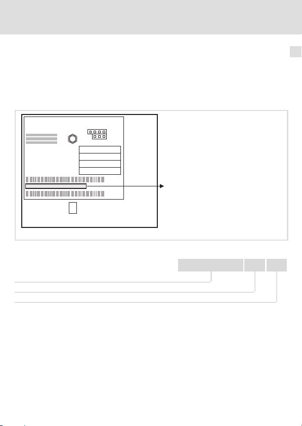
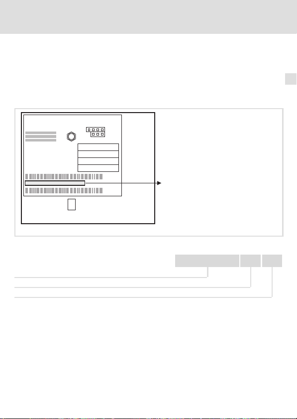
Identifikation
L
Type
Id.-No.
Prod.-No.
MAC-ID
E82AF000P0B201XX
Produktbeschreibung
Lieferumfang
2191EPL013
3
Gerätereihe
Hardwarestand
Softwarestand
EDK2191DB DE/EN/FR 2.0
33.2191IB VA 10
9
Page 10

4 Technische Daten
Allgemeine Daten
4 Technische Daten
Allgemeine Daten
Bereich Werte
Bestell−Bezeichnung EMF2191IB
Kommunikationsprofil Ethernet POWERLINK V2
Schnittstelle RJ45, Fast Ethernet Modus MII (nach IEEE 802.3)
Kommunikationsmedium TP (100BaseTX, Cat5e)
Kabellänge max. 100 m zwischen 2 Teilnehmern / Hubs
Gesamtausdehnung Teilnehmeranzahl x 100 m
Netzwerk−Topologie Baum, Stern, Linie
Übertragungsmodus Halbduplex
Teilnehmertyp Slave (CN, Controlled Node)
Knotenadressen Max. 239
Konformitäten, Approbationen
Übertragungsrate 100 MBit/s
Spannungsversorgung Externe Versorgung über separates Netzteil
l CE
l cUL
+U =
24VDC(20,4 V − 0%... 28,8 V+ 0%)
I =
140 mA
Bezugspotenzial für externe Spannungsversorgung
−
Dokumentationen zu Lenze Gerätereihen 8200 vector, 9300 und ECS
Hier finden Sie die Umgebungsbedingungen und Daten zur
Elektromagnetischen Verträglichkeit (EMV), die auch für das
Kommunikationsmodul gelten.
10
EDK2191DB DE/EN/FR 2.0
Page 11
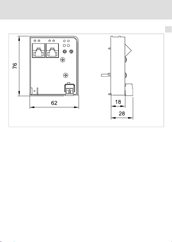
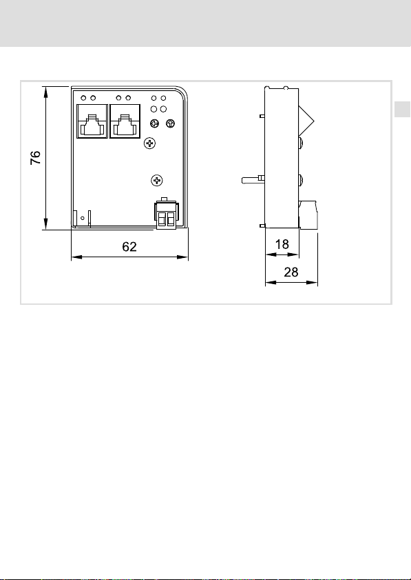
Abmessungen
alle Maße in mm
Technische Daten
Abmessungen
2191EPL001B
4
EDK2191DB DE/EN/FR 2.0
11
Page 12

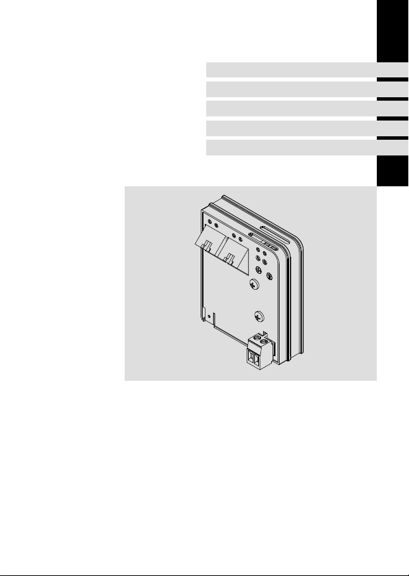
5 Mechanische Installation
5 Mechanische Installation
Abb. 1 Kommunikationsmodul aufstecken
ƒ Stecken Sie das Kommunikationsmodul auf das Grundgerät (hier: 8200 vector).
ƒ Schrauben Sie das Kommunikationsmodul mit der Befestigungsschraube auf dem
Grundgerät fest, um eine gute PE−Verbindung sicher zu stellen.
2102LEC014
Hinweis!
Zur internen Versorgung des Kommunikationsmoduls durch den
Frequenzumrichter 8200 vector muss der Jumper in der Schnittstellenöffnung
(siehe Abb. oben) angepasst werden.
Beachten Sie die Hinweise (16).
12
EDK2191DB DE/EN/FR 2.0
Page 13

Elektrische Installation
EMV−gerechte Verdrahtung
6 Elektrische Installation
EMV−gerechte Verdrahtung
Für eine EMV−gerechte Verdrahtung beachten Sie folgende Punkte:
Hinweis!
ƒ Steuer−/Datenleitungen getrennt von Motorleitungen verlegen.
ƒ Legen Sie die Schirme der Steuer−/Datenleitungen bei digitalen Signalen
beidseitig auf.
ƒ Zur Vermeidung von Potenzialdifferenzen zwischen den
Kommunikationsteilnehmern eine Ausgleichsleitung mit einem
Querschnitt von mindestens 16mm
ƒ Beachten Sie die weiteren Hinweise zur EMV−gerechten Verdrahtung in der
Dokumentation des Grundgerätes.
Vorgehensweise bei der Verdrahtung
1. Bustopologie einhalten, deshalb keine Stichleitungen verwenden.
2. Hinweise und Verdrahtungsvorschriften in den Unterlagen zum Steuerungssystem
beachten.
3. Nur Kabel verwenden, die den aufgeführten Spezifikationen entsprechen (15).
4. Hinweise zur Spannungsversorgung des Moduls beachten (16).
2
einsetzen (Bezug:PE).
6
EDK2191DB DE/EN/FR 2.0
13
Page 14

6 Elektrische Installation
POWERLINK−Anschluss
POWERLINK−Anschluss
Zum Anschluss des Kommunikationsmoduls an den Feldbus eignet sich ein handelsübliches Standard−Ethernet−Patchkabel (siehe "Spezifikation des Ethernet−Kabels" (15)).
Hinweis!
Um Beschädigungen der RJ45−Buchse zu vermeiden, den Stecker des
Ethernet−Kabels gerade (im rechten Winkel) in die Buchse stecken bzw. aus der
Buchse ziehen.
Pinbelegung
RJ45−Buchse Pin Signal
1 Tx +
2 Tx −
3 Rx +
E94AYCXX004C
4 −
5 −
6 Rx−
7 −
8 −
Tipp!
Die POWERLINK−Schnittstellen verfügen über eine Auto−MDIX−Funktion. Diese
Funktion passt die Polung der RJ45−Schnittstellen so an, dass unabhängig von
der Polung der gegenüberliegenden POWERLINK−Schnittstelle und dem
verwendeten Kabeltyp (Standard−Patch−Kabel oder Cross−Over−Kabel) eine
Verbindung hergestellt wird.
14
EDK2191DB DE/EN/FR 2.0
Page 15

Elektrische Installation
POWERLINK−Anschluss
Spezifikation des Ethernet−Kabels
Hinweis!
Verwenden Sie ausschließlich Kabel, die den aufgeführten Spezifikationen
entsprechen.
Spezifikation des Ethernet−Kabels
Ethernet−Standard Standard Ethernet (nach IEEE 802.3), 100Base−TX (Fast Ethernet)
Kabeltyp S/FTP (Screened Foiled Twisted Pair), ISO/IEC 11801 oder
Dämpfung 23.2 dB (bei 100 MHz und je 100 m)
Nebensprechdämpfung 24 dB (bei 100 MHz und je 100 m)
Rückflussdämpfung 10 dB (je 100 m)
Wellenwiderstand
EN 50173, CAT 5e
100
6
EDK2191DB DE/EN/FR 2.0
15
Page 16

6 Elektrische Installation
Spannungsversorgung
Spannungsversorgung
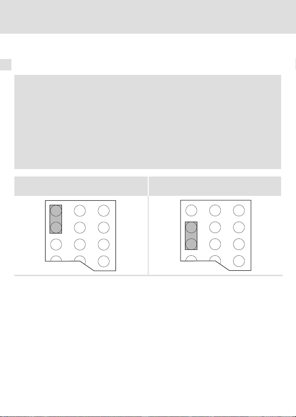
Interne Spannungsversorgung
Hinweis!
Die Vorgabe der internen Spannungsversorgung ist bei Grundgeräten mit
erweiterter AIF−Schnittstellenöffnung (z. B. Frontseite 8200 vector) gegeben.
Die in der Grafik grau hervorgehobene Fläche kennzeichnet die
Jumper−Position.
ƒ Im Auslieferungszustand des Grundgerätes werden diese nicht intern
versorgt.
ƒ Zur internen Spannungsversorgung platzieren Sie den Jumper auf die
unten angegebene Position.
Bei allen anderen Gerätereihen (9300, ECS) ist eine Spannungsversorgung vom
Grundgerät immer vorhanden.
(Nur externe Spannungsversorgung möglich.)
Auslieferungszustand
Interne Spannungsversorgung
16
EDK2191DB DE/EN/FR 2.0
Page 17

Elektrische Installation
Spannungsversorgung
Externe Spannungsversorgung
Hinweis!
Verwenden Sie bei externer Spannungsversorgung und bei größeren
Entfernungen zwischen den Schaltschränken in jedem Schaltschrank immer
ein separates und nach EN 61800−5−1 sicher getrenntes Netzteil (SELV/PELV).
Die externe Spannungsversorgung des Kommunikationsmoduls ...
ƒ ist notwendig, wenn beim Ausfall der Versorgung des Grundgerätes die
Kommunikation über den Feldbus bestehen bleiben soll.
ƒ erfolgt über die 2−polige Steckerleiste mit Schraubanschluss (24 V DC):
Klemme Beschreibung
+ Externe Spannungsversorgung
− Bezugspotenzial für externe Spannungsversorgung
ƒ Der Zugriff auf Parameter eines vom Netz getrennten Grundgerätes ist nicht
möglich.
Daten der Anschlussklemmen
Bereich Werte
Elektrischer Anschluss Steckerleiste mit Schraubanschluss
Anschlussmöglichkeiten
Anzugsmoment 0.5 ... 0.6 Nm (4.4 ... 5.3 lb−in)
Abisolierlänge 6 mm
U = 24VDC(20.4 V − 0%... 28.8 V +0%)
I = 85 mA
starr:
flexibel:
2
1.5 mm
(AWG 16)
ohne Aderendhülse
2
(AWG 16)
1.5 mm
mit Aderendhülse, ohne Kunststoffhülse
2
(AWG 16)
1.5 mm
mit Aderendhülse, mit Kunststoffhülse
2
(AWG 16)
1.5 mm
6
EDK2191DB DE/EN/FR 2.0
17
Page 18

7 Inbetriebnahme
Vor dem ersten Einschalten
7 Inbetriebnahme
Vor dem ersten Einschalten
Stop!
Bevor Sie das Grundgerät mit dem Kommunikationsmodul erstmalig
einschalten, überprüfen Sie die gesamte Verdrahtung auf Vollständigkeit,
Kurzschluss und Erdschluss.
Kommunikationshandbuch EMF2191IB (POWERLINK)
Hier finden Sie ausführliche Informationen zur Inbetriebnahme des
Kommunikationsmoduls.
18
EDK2191DB DE/EN/FR 2.0
Page 19

Teilnehmeradresse einstellen
Teilnehmeradresse einstellen
Hinweis!
ƒ Die Knotenadressen bei mehreren vernetzten Antriebsreglern müssen sich
voneinander unterscheiden.
Die Lenze−Einstellung für die Knotenadresse (Node ID) hat den Wert ’4’:
– linker Schalter in Stellung ’0’
– rechter Schalter in Stellung ’4’
ƒ Um geänderte Einstellungen zu aktivieren, schalten Sie die
Spannungsversorgung des Antriebsreglers/Kommunikationsmoduls aus
und anschließend wieder ein.
Abb. 2 Einstellen der Teilnehmeradresse
Jedem Teilnehmer muss eine eindeutige Adresse (Node ID) zugewiesen werden.
ƒ Gültiger Adressbereich für Slave (Controlled Node): 1 ... 239
ƒ Die zugehörige IP−Adresse des Kommunikationsmoduls ergibt sich aus der
Einstellung der beiden Drehschalter.
IP−Adresse: 192.168.100.<Node ID>
(Wert{linkerSchalter} 16))(Wert{rechterSchalter}) + Knotenadresse
Inbetriebnahme
7
2191EPL001B
EDK2191DB DE/EN/FR 2.0
19
Page 20
8 Diagnose
8 Diagnose
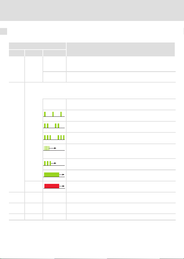
Zur Störungsdiagnose stehen für das Kommunikationsmodul die auf der Frontseite platzierten LEDs zur Verfügung.
LED
Pos. Farbe Zustand
grün
aus Das Kommunikationsmodul ist mit Spannung versorgt, hat aber
an Das Kommunikationsmodul ist mit Spannung versorgt und hat
grün
Die NMT−Statusmaschine steuert die zweifarbige LED an:
l grün: Anzeige von Statusmeldungen
l rot: Anzeige von Fehlermeldungen
aus NMT_GS_OFF, NMT_GS_INITIALISATION,
rot ERROR
rot an Die rote und grüne Drive−LED kennzeichnet den Betriebszustand
grün blinkt Je nach Verbindungszustand werden Daten gesendet oder emp-
gelb an Ethernet−Verbindung ist vorhanden (LINK).
Beschreibung
keine Verbindung zum Grundgerät (Grundgerät ist ausgeschaltet,
in der Initialisierungsphase oder nicht vorhanden).
eine Verbindung zum Grundgerät.
NMT_CS_NOT_ACTIVE / NMT_MS_NOT_ACTIVE
NMT_CS_PREOPERATIONAL_1 / NMT_MS_PREOPERATIONAL_1
(LED blitzt innerhalb einer Sekunde einmal auf.)
NMT_CS_PREOPERATIONAL_2 / NMT_MS_PREOPERATIONAL_2
(LED blitzt innerhalb einer Sekunde zweimal auf.)
NMT_CS_READY_TO_OPERATE / NMT_MS_READY_TO_OPERATE
(LED blitzt innerhalb einer Sekunde dreimal auf.)
NMT_CS_BASIC_ETHERNET
(LED blinkt mit einer Frequenz von 10 Hz oder je nach Verbindungszustand)
NMT_CS_STOPPED
(LED blinkt mit einer Frequenz von 2,5 Hz.)
NMT_CS_OPERATIONAL / NMT_MS_OPERATIONAL
(LED leuchtet dauerhaft.)
(LED leuchtet dauerhaft. Ein Fehler liegt vor.)
des Grundgerätes (siehe Dokumentation des Grundgerätes).
fangen (ACTIVITY).
20
EDK2191DB DE/EN/FR 2.0
Page 21

Diagnose 8
EDK2191DB DE/EN/FR 2.0
21
Page 22

Displays
Pos. Description
LED status displays for diagnostics
...
Connections
Pos. Description
POWERLINK connection
Version: RJ45 socket according to IEC 60603−7
Connection to external supply of the communication module
Version: Connector with screw connection, 2−pole
Switch
Pos. Description
Switches for addressing the nodes
l Left switch: Setting with factor 16
l Right switch: Setting with factor 1
The addition of both products results in the node address (node ID)
Node ID = 254 (the node ID is obtained from a DHCP server)
0Fig. 0Tab. 0
22
EDK2191DB DE/EN/FR 2.0
Page 23

Contents i
1 About this documentation 24. . . . . . . . . . . . . . . . . . . . . . . . . . . . . . . . . . . . . . . . . . . .
2 Safety instructions 25. . . . . . . . . . . . . . . . . . . . . . . . . . . . . . . . . . . . . . . . . . . . . . . . . . .
3 Product description 26. . . . . . . . . . . . . . . . . . . . . . . . . . . . . . . . . . . . . . . . . . . . . . . . . .
Function 26. . . . . . . . . . . . . . . . . . . . . . . . . . . . . . . . . . . . . . . . . . . . . . . . . . . . . . . . . . .
Application as directed 26. . . . . . . . . . . . . . . . . . . . . . . . . . . . . . . . . . . . . . . . . . . . . .
Scope of supply 27. . . . . . . . . . . . . . . . . . . . . . . . . . . . . . . . . . . . . . . . . . . . . . . . . . . . . .
Identification 27. . . . . . . . . . . . . . . . . . . . . . . . . . . . . . . . . . . . . . . . . . . . . . . . . . . . . . .
4 Technical data 28. . . . . . . . . . . . . . . . . . . . . . . . . . . . . . . . . . . . . . . . . . . . . . . . . . . . . . .
General data 28. . . . . . . . . . . . . . . . . . . . . . . . . . . . . . . . . . . . . . . . . . . . . . . . . . . . . . .
Dimensions 29. . . . . . . . . . . . . . . . . . . . . . . . . . . . . . . . . . . . . . . . . . . . . . . . . . . . . . . . .
5 Mechanical installation 30. . . . . . . . . . . . . . . . . . . . . . . . . . . . . . . . . . . . . . . . . . . . . . .
6 Electrical installation 31. . . . . . . . . . . . . . . . . . . . . . . . . . . . . . . . . . . . . . . . . . . . . . . . .
Wiring according to EMC 31. . . . . . . . . . . . . . . . . . . . . . . . . . . . . . . . . . . . . . . . . . . . . .
POWERLINK connection 32. . . . . . . . . . . . . . . . . . . . . . . . . . . . . . . . . . . . . . . . . . . . . . .
Voltage supply 34. . . . . . . . . . . . . . . . . . . . . . . . . . . . . . . . . . . . . . . . . . . . . . . . . . . . .
7 Commissioning 36. . . . . . . . . . . . . . . . . . . . . . . . . . . . . . . . . . . . . . . . . . . . . . . . . . . . .
Before switching on 36. . . . . . . . . . . . . . . . . . . . . . . . . . . . . . . . . . . . . . . . . . . . . . . . .
Setting the node address 37. . . . . . . . . . . . . . . . . . . . . . . . . . . . . . . . . . . . . . . . . . . . .
8 Diagnostics 38. . . . . . . . . . . . . . . . . . . . . . . . . . . . . . . . . . . . . . . . . . . . . . . . . . . . . . . . .
EDK2191DB DE/EN/FR 2.0
23
Page 24

1 About this documentation
1 About this documentation
Contents
This documentation contains ...
ƒ information on mechanical and electrical installation of the communication module;
ƒ Safety instructions that must be observed;
ƒ Information on versions of the Lenze standard devices to be used;
ƒ technical data of the communication module;
ƒ descriptions of the LED status displays for diagnostics.
Tip!
Further information regarding this communication module can be found in
the corresponding communication manual.
The PDF file can be found in the download area at
http://www.Lenze.com
Validity information
The information in this documentation applies to the following devices:
Extension module Type designation From hardware version From software version
POWERLINK
communication
module
Target group
This documentation is intended for persons who install and commission the described
product according to the project requirements.
EMF2191IB VA 1.0
Tip!
Information and auxiliary devices related to the Lenze products can be found
in the download area at
http://www.Lenze.com
24
EDK2191DB DE/EN/FR 2.0
Page 25

Safety instructions 2
2 Safety instructions
Stop!
Electrostatic discharge
Electronic components of the communication module can be damaged or
destroyed through electrostatic discharge.
Possible consequences:
ƒ The communication module is damaged.
ƒ Fieldbus communication is not possible or faulty.
Protective measures
ƒ Discharge electrostatic charges before touching the module.
ƒ During operation, the communication module must be securely connected to the
standard device.
ƒ With external voltage supply, always use a separate power supply unit, safely
separated in accordance with EN 61800−5−1 in every control cabinet (SELV/PELV).
ƒ Only use cables that meet the given specifications. (33)
Documentation of the standard device, control system, and plant/machine
All the other measures prescribed in this documentation must also be
implemented. Observe the safety instructions and application notes contained
in this manual.
EDK2191DB DE/EN/FR 2.0
25
Page 26

3 Product description
Function
3 Product description
Function
The communication module connects the Lenze inverter to the Ethernet POWERLINK
communication system.
Application as directed
The communication module ...
ƒ is a device intended for use in industrial power systems;
ƒ can only be used in POWERLINK networks;
ƒ can be used together with the following standard devices (nameplate data):
Device type Design
82EVxxxxxBxxxXX
82CVxxxxxBxxxXX
82DVxxxKxBxxxXX
EPL 10200 E
33.93XX xE.
33.938X xE.
33.93XX xC.
33.93XX EI / ET
33.93XX CI / CT
ECSxSxxxx4xxxxXX
ECSxPxxxx4xxxxXX
ECSxMxxxx4xxxxXX
ECSxAxxxx4xxxxXX
ECSxExxxx4xxxxXX
1) operating system software versions of the controllers
Version
HW SW
Vx 1x
Vx 1x
Vx 1x
1x 1x
2x 1x
1x 0x
2x 1x
2x 1x
2x 1x
1A 6.0
1A 6.0
1A 6.0
1A 2.3
VA 3.0
Any other use shall be deemed inappropriate!
Variant Explanation
1)
8200 vector
8200 vector, cold plate
8200 vector, thermally
separated
Drive PLC
Vxxx 9321 − 9332 vector
9381 − 9383 vector
Vxxx 9321 − 9332, with cold
plate version
Vxxx 9300 Servo PLC
Vxxx 9300 Servo PLC, cold plate
ECSxS "Speed & Torque"
ECSxP "Posi & Shaft"
ECSxM "Motion"
ECSxA "Application"
ECSxE power supply
module
26
EDK2191DB DE/EN/FR 2.0
Page 27

Scope of supply
ƒ Communication module EMF2191IB (POWERLINK)
ƒ Mounting Instructions
Identification
L
Type
Id.-No.
Prod.-No.
MAC-ID
E82AF000P0B201XX
Product description
Scope of supply
2191EPL013
3
Device series
Hardware version
Software version
EDK2191DB DE/EN/FR 2.0
33.2191IB VA 10
27
Page 28

4 Technical data
General data
4 Technical data
General data
Field Values
Order designation EMF2191IB
Communication profile Ethernet POWERLINK V2
Interface RJ45, Fast Ethernet Mode MII (according to IEEE 802.3)
Communication medium TP (100BaseTX, Cat5e)
Cable length max. 100 m between 2 nodes / hubs
Total extension Number of nodes x 100 m
Network topology Tree, star, line
Transmission mode Half duplex
Type of node Slave (CN, Controlled Node)
Node address Max. 239
Conformities, approvals
Baud rate 100 Mbps
Voltage supply External supply via separate power supply unit
l CE
l cUL
+V =
24VDC(20.4 V − 0%... 28.8 V+ 0%)
I =
140 mA
Reference potential for external voltage supply
−
Documentation for Lenze series of devices 8200 vector, 9300 and ECS
Here you can find the ambient conditions and the electromagnetic
compatibility (EMC) specifications applying to the communication module.
28
EDK2191DB DE/EN/FR 2.0
Page 29

Dimensions
All dimensions in mm
Technical data
Dimensions
2191EPL001B
4
EDK2191DB DE/EN/FR 2.0
29
Page 30

5 Mechanical installation
5 Mechanical installation
Fig. 1 Attaching the communication module
ƒ Plug the communication module onto the standard device (here: 8200 vector).
ƒ Tighten the communication module to the standard device using the fixing screw in
order to ensure a good PE connection.
2102LEC014
Note!
For the internal supply of the communication module by the 8200 vector
frequency inverter the jumper has to be adjusted within the interface opening
(see illustration above).
Observe the notes (34).
30
EDK2191DB DE/EN/FR 2.0
Page 31

Electrical installation
Wiring according to EMC
6 Electrical installation
Wiring according to EMC
For wiring according to EMC requirements observe the following points:
Note!
ƒ Separate control cables/data lines from motor cables.
ƒ Connect the shields of control cables/data lines at both ends in the case of
digital signals.
ƒ Use an equalizing conductor with a cross−section of at least 16mm
(reference:PE) to avoid potential differences between the bus nodes.
ƒ Observe the other notes concerning EMC−compliant wiring given in the
documentation for the standard device.
Wiring procedure
1. Comply with bus topology, thus do not use stubs.
2. Observe notes and wiring instructions in the documents for the control system.
3. Only use cables that comply with the given specifications (33).
4. Observe notes for the voltage supply of the module (34).
2
6
EDK2191DB DE/EN/FR 2.0
31
Page 32

6 Electrical installation
POWERLINK connection
POWERLINK connection
You can use a standard Ethernet patch cable for connecting the communication module to
the fieldbus (see "Ethernet cable specifications" (33)).
Note!
Plug/remove the Ethernet cable plug in a straight manner (at right angles)
into/from the socket to make sure that the RJ45 socket will not be damaged.
Pin assignment
RJ45 socket PIN Signal
1 Tx +
2 Tx −
3 Rx +
E94AYCXX004C
4 −
5 −
6 Rx −
7 −
8 −
Tip!
The POWERLINK interfaces feature an auto MDIX function. This function
adjusts the polarity of the RJ45 interfaces so that a connection is established
irrespective of the polarity of the opposite POWERLINK interface, and
irrespective of the type of cable used (standard patch cable or crossover cable).
32
EDK2191DB DE/EN/FR 2.0
Page 33

Electrical installation
POWERLINK connection
Ethernet cable specifications
Note!
Only use cables complying with the below specifications.
Ethernet cable specifications
Ethernet standard Standard Ethernet (according to IEEE 802.3), 100base TX (fast
Cable type S/FTP (Screened Foiled Twisted Pair), ISO/IEC 11801 or EN 50173,
Damping 23.2 dB (at 100 MHz and per 100 m)
Crosstalk damping 24 dB (at 100 MHz and per 100 m)
Return loss 10 dB (per 100 m)
Surge impedance
Ethernet)
CAT 5e
100
6
EDK2191DB DE/EN/FR 2.0
33
Page 34
6 Electrical installation
Voltage supply
Voltage supply
Internal voltage supply
Note!
Internal voltage supply has been selected in the case of standard devices with
an extended AIF interface opening (e.g. front of 8200 vector). The area shown
on a grey background in the graphic marks the jumper position.
ƒ By default, this is not supplied internally in the standard device.
ƒ For internal voltage supply place the jumper on the position indicated
below.
In the case of all other device series (9300, ECS), voltage is always supplied
from the standard device.
(Only external voltage supply possible.)
34
Lenze setting
Internal voltage supply
EDK2191DB DE/EN/FR 2.0
Page 35

Electrical installation
Voltage supply
External voltage supply
Note!
In the case of an external voltage supply and for greater distances between the
control cabinets, always use a separate power supply unit (SELV/PELV) that is
safely separated in accordance with EN 61800−5−1 in each control cabinet.
The external voltage supply of the communication module ...
ƒ is required if communication via the fieldbus is to be continued when the supply of
the device fails.
ƒ is provided via the 2−pin terminal strip with screw−type connection (24 V DC):
Terminal Description
+ External voltage supply
− Reference potential for external voltage supply
ƒ The parameters of a standard device disconnected from the mains cannot be
accessed.
Terminal data
Area Values
Electrical connection Plug connector with screw connection
Possible connections
Tightening torque 0.5 ... 0.6 Nm (4.4 ... 5.3 lb−in)
Stripping length 6 mm
U = 24VDC(20.4 V − 0%... 28.8 V +0%)
I = 85 mA
rigid:
flexible:
2
1.5 mm
(AWG 16)
without wire end ferrule
2
(AWG 16)
1.5 mm
with wire end ferrule, without plastic sleeve
2
(AWG 16)
1.5 mm
with wire end ferrule, with plastic sleeve
2
(AWG 16)
1.5 mm
6
EDK2191DB DE/EN/FR 2.0
35
Page 36

7 Commissioning
Before switching on
7 Commissioning
Before switching on
Stop!
Before switching on the standard device with the communication module for
the first time, check the entire wiring for completeness, short circuit and earth
fault.
Communication manual EMF2191IB (POWERLINK)
Here you will find detailed information on how to commission the
communication module.
36
EDK2191DB DE/EN/FR 2.0
Page 37

Commissioning
Setting the node address
Setting the node address
Note!
ƒ Use different node addresses for several networked inverters.
The Lenze setting for the node address (node ID) has the value ’4’:
– link switch in position ’0’
– right switch in position ’4’
ƒ Switch the voltage supply of the inverter/communication module off and
on again to activate changed settings.
2191EPL001B
Fig. 2 Setting the node address
Each node has to be assigned to a unique address (node ID).
ƒ Valid address range for slave (controlled node): 1 ... 239
ƒ The corresponding IP address of the communication module results from the setting
of the two rotary switches.
IP address: 192.168.100.<Node ID>
(ValueNJLeftSwitchNj 16))(Value
NJ
RightSwitchNj) + NodeAddress
7
EDK2191DB DE/EN/FR 2.0
37
Page 38

8 Diagnostics
8 Diagnostics
The LEDs on the front are provided to the communication module for the purpose of fault
diagnostics.
LED
Pos. Colour Condition
green
off The communication module is supplied with voltage, but has no
on The communication module is supplied with voltage and is
green
The NMT state machine triggers the two−colored LED:
l Green: Display of status messages
l Red: Display of error messages
off NMT_GS_OFF, NMT_GS_INITIALISATION,
red ERROR
red on The red and green drive LED indicates the operating status of the
green blinking Depending on the connection state, the data is transmitted or
yellow on Ethernet connection is available (LINK).
Description
connection to the basic device (basic device is either switched off,
in the initialisation phase, or not available).
connected to the standard device.
NMT_CS_NOT_ACTIVE / NMT_MS_NOT_ACTIVE
NMT_CS_PREOPERATIONAL_1 / NMT_MS_PREOPERATIONAL_1
(LED flashes once within a second.)
NMT_CS_PREOPERATIONAL_2 / NMT_MS_PREOPERATIONAL_2
(LED flashes twice within a second.)
NMT_CS_READY_TO_OPERATE / NMT_MS_READY_TO_OPERATE
(LED flashes three times within a second.)
NMT_CS_BASIC_ETHERNET
(LED is blinking with a frequency of 10 Hz or depending on the
connection state)
NMT_CS_STOPPED
(LED is blinking with a frequency of 2.5 Hz.)
NMT_CS_OPERATIONAL / NMT_MS_OPERATIONAL
(LED is lit permanently.)
(LED is lit permanently. An error has occurred.)
standard device (see documentation of the standard device).
received (ACTIVITY).
38
EDK2191DB DE/EN/FR 2.0
Page 39

Diagnostics 8
EDK2191DB DE/EN/FR 2.0
39
Page 40

Affichages
Pos. Description
Affichages d’état (LED) pour diagnostic
...
Raccordements
Pos. Description
Raccordement POWERLINK
Version : prise RJ45 suivant CEI 60603−7
Raccordement pour l’alimentation externe du module de communication
Version : bornier à vis, 2 bornes
Commutateur
Pos. Description
Commutateurs pour adressage du participant au bus
l Commutateur de gauche : réglage avec facteur 16
l Commutateur de droite : réglage avec facteur 1
La somme des deux réglages donne l’adresse (identificateur nœud) du participant au bus.
Identificateur nœud = 254 (l’identificateur nœud est attribué par un serveur DHCP)
0Fig. 0Tab. 0
40
EDK2191DB DE/EN/FR 2.0
Page 41

Sommaire i
1 Présentation du document 42. . . . . . . . . . . . . . . . . . . . . . . . . . . . . . . . . . . . . . . . . . . .
2 Consignes de sécurité 43. . . . . . . . . . . . . . . . . . . . . . . . . . . . . . . . . . . . . . . . . . . . . . . .
3 Description du produit 44. . . . . . . . . . . . . . . . . . . . . . . . . . . . . . . . . . . . . . . . . . . . . . . .
Fonction 44. . . . . . . . . . . . . . . . . . . . . . . . . . . . . . . . . . . . . . . . . . . . . . . . . . . . . . . . . . .
Utilisation conforme à la fonction 44. . . . . . . . . . . . . . . . . . . . . . . . . . . . . . . . . . . . .
Equipement livré 45. . . . . . . . . . . . . . . . . . . . . . . . . . . . . . . . . . . . . . . . . . . . . . . . . . . .
Identification 45. . . . . . . . . . . . . . . . . . . . . . . . . . . . . . . . . . . . . . . . . . . . . . . . . . . . . . .
4 Spécifications techniques 46. . . . . . . . . . . . . . . . . . . . . . . . . . . . . . . . . . . . . . . . . . . . .
Caractéristiques générales 46. . . . . . . . . . . . . . . . . . . . . . . . . . . . . . . . . . . . . . . . . . . .
Encombrements 47. . . . . . . . . . . . . . . . . . . . . . . . . . . . . . . . . . . . . . . . . . . . . . . . . . . . .
5 Installation mécanique 48. . . . . . . . . . . . . . . . . . . . . . . . . . . . . . . . . . . . . . . . . . . . . . .
6 Installation électrique 49. . . . . . . . . . . . . . . . . . . . . . . . . . . . . . . . . . . . . . . . . . . . . . . .
Câblage conforme CEM 49. . . . . . . . . . . . . . . . . . . . . . . . . . . . . . . . . . . . . . . . . . . . . . .
Raccordement POWERLINK 50. . . . . . . . . . . . . . . . . . . . . . . . . . . . . . . . . . . . . . . . . . . .
Alimentation 52. . . . . . . . . . . . . . . . . . . . . . . . . . . . . . . . . . . . . . . . . . . . . . . . . . . . . . .
7 Mise en service 54. . . . . . . . . . . . . . . . . . . . . . . . . . . . . . . . . . . . . . . . . . . . . . . . . . . . . .
Avant la première mise sous tension 54. . . . . . . . . . . . . . . . . . . . . . . . . . . . . . . . . . . .
Réglage de l’adresse des participants 55. . . . . . . . . . . . . . . . . . . . . . . . . . . . . . . . . . .
8 Diagnostic 56. . . . . . . . . . . . . . . . . . . . . . . . . . . . . . . . . . . . . . . . . . . . . . . . . . . . . . . . . .
EDK2191DB DE/EN/FR 2.0
41
Page 42

1 Présentation du document
1 Présentation du document
Contenu
Cette documentation contient ...
ƒ des informations relatives à l’installation mécanique et l’installation électrique du
module de communication,
ƒ des consignes de sécurité qui doivent impérativement être respectées,
ƒ les indications des versions des appareils de base Lenze à utiliser,
ƒ les spécifications techniques du module de communication,
ƒ les descriptions des affichages d’état (LED) pour diagnostic.
Conseil !
Pour plus d’informations sur le module de communication, consulter le
manuel de communication correspondant.
Le fichier au format PDF peut être téléchargé à l’adresse suivante :
http://www.Lenze.com
Validité
Les informations contenues dans la présente documentation concernent les appareils
suivants :
Module d’extension Référence de
Module de
communication
POWERLINK
Public visé
Ce document est destiné aux personnes chargées d’installer et de mettre en service le
produit décrit selon les exigences du projet.
commande
EMF2191IB VA 1.0
À partir de la version
matérielle
À partir de la version
logicielle
Conseil !
Toutes les informations relatives aux produits Lenze peuvent être téléchargées
sur notre site à l’adresse suivante :
http://www.Lenze.com
42
EDK2191DB DE/EN/FR 2.0
Page 43

Consignes de sécurité 2
2 Consignes de sécurité
Stop !
Décharge électrostatique
Des composants électroniques à l’intérieur du module de communication
peuvent être endommagés ou détruits par des décharges électrostatiques.
Risques encourus :
ƒ Le module de communication est endommagé.
ƒ La communication par bus de terrain est impossible ou erronée.
Mesures de protection :
ƒ Se libérer des décharges électrostatiques avant toute manipulation du
module de communication.
ƒ Pendant le fonctionnement, le module de communication doit être relié à l’appareil
de base en permanence.
ƒ En cas d’alimentation externe, toujours utiliser un bloc d’alimentation avec coupure
de sécurité (SELV/PELV) distinct et conforme à la norme EN 61800−5−1 pour chaque
armoire électrique.
ƒ Utiliser exclusivement des câbles conformes aux spécifications indiquées (51).
Documentation relative à l’appareil de base, au système de commande, à
l’installation/la machine
Il faut également prévoir toutes les mesures indiquées dans ces documents.
Tenir impérativement compte des consignes de sécurité et d’utilisation
fournies.
EDK2191DB DE/EN/FR 2.0
43
Page 44

3 Description du produit
Fonction
3 Description du produit
Fonction
Le module de communication relie le variateur de vitesse Lenze au système Ethernet
POWERLINK.
Utilisation conforme à la fonction
Le module de communication...
ƒ est un équipement à utiliser dans des installations industrielles à courant fort ;
ƒ s’utilise uniquement dans les réseaux POWERLINK ;
ƒ peut être utilisé avec les appareils de base suivants (voir plaques signalétiques) :
Type d’appareil Version
82EVxxxxxBxxxXX
82CVxxxxxBxxxXX
82DVxxxKxBxxxXX
EPL 10200 E
33.93XX xE.
33.938X xE.
33.93XX xC.
33.93XX EI / ET
33.93XX CI / CT
ECSxSxxxx4xxxxXX
ECSxPxxxx4xxxxXX
ECSxMxxxx4xxxxXX
ECSxAxxxx4xxxxXX
ECSxExxxx4xxxxXX
d’appareil
HW SW
Vx 1x
Vx 1x
Vx 1x
1x 1x
2x 1x
1x 0x
2x 1x
2x 1x
2x 1x
1A 6.0
1A 6.0
1A 6.0
1A 2.3
VA 3.0
1) Versions logicielles du système d’exploitation des variateurs
Toute autre utilisation est contre−indiquée !
Version
Variante Description
1)
8200 vector
8200 vector, montage sur
semelle de refroidissement
8200 vector, séparation
thermique
Drive PLC
Vxxx 9321 − 9332 vector
9381 − 9383 vector
Vxxx 9321 − 9332, vector avec
montage sur semelle de
refroidissement
Vxxx 9300 Servo PLC
Vxxx 9300 Servo PLC, montage
sur semelle de
refroidissement
ECSxS "Speed & Torque"
ECSxP "Posi & Shaft"
ECSxM "Motion"
ECSxA "Application"
Module d’alimentation
ECSxE
44
EDK2191DB DE/EN/FR 2.0
Page 45
Description du produit
Equipement livré
ƒ Module de communication EMF2191IB (POWERLINK)
ƒ Instructions de montage
Identification
L
Type
Id.-No.
Prod.-No.
MAC-ID
E82AF000P0B201XX
Equipement livré
3
2191EPL013
Série d’appareils
Version matérielle
Version logicielle
EDK2191DB DE/EN/FR 2.0
33.2191IB VA 10
45
Page 46

4 Spécifications techniques
Caractéristiques générales
4 Spécifications techniques
Caractéristiques générales
Domaine Valeurs
Référence de commande EMF2191IB
Profil de communication Ethernet POWERLINK V2
Interface RJ45, Fast Ethernet Modus MII (selon IEEE 802.3)
Support de communication TP (100BaseTX, Cat5e)
Longueur de câble 100 m max. entre 2 participants/répétiteurs (Hubs)
Longueur maximale Nombre de participants x 100 m
Topologie du réseau Arborescence, étoile, ligne
Mode de transmission Semi−duplex
Type de participant Esclave (nœud CN (Controlled Node))
Adresses de nœud 239 max.
Normes appliquées, homologations
Vitesse de transmission 100 Mbits/s
Alimentation Alimentation externe via bloc d’alimentation séparé
l CE
l cUL
+U =
24VCC(20.4 V − 0%... 28.8 V+ 0%)
I =
140 mA
Potentiel de référence pour l’alimentation externe
−
Documentations relatives aux séries d’appareils Lenze 8200 vector, 9300 et
ECS
Ces documentations décrivent les conditions ambiantes et les données de
compatibilité électromagnétique (CEM), qui sont également valables pour le
module de communication.
46
EDK2191DB DE/EN/FR 2.0
Page 47
Encombrements
Toutes les cotes en mm
Spécifications techniques
Encombrements
2191EPL001B
4
EDK2191DB DE/EN/FR 2.0
47
Page 48

5 Installation mécanique
5 Installation mécanique
Fig. 1 Brancher le module de communication
ƒ Enficher le module de communication dans l’appareil de base (ici : 8200 vector).
ƒ Visser le module de communication sur l’appareil de base à l’aide de la vis de fixation
pour assurer une bonne liaison avec la terre.
2102LEC014
Remarque importante !
Pour l’alimentation interne du module de communication par le convertisseur
de fréquence 8200 vector, le cavalier doit être inséré dans l’ouverture prévue à
cet effet (voir schéma ci−dessus).
Voir également les remarques fournies (52).
48
EDK2191DB DE/EN/FR 2.0
Page 49

Installation électrique
Câblage conforme CEM
6 Installation électrique
Câblage conforme CEM
Pour s’assurer que le câblage est conforme aux exigences à respecter en matière de CEM,
vérifier les points suivants :
Remarque importante !
ƒ Séparer physiquement les câbles de commande/de données des câbles
moteur.
ƒ Pour les signaux numériques, blinder les câbles de commande et de
données aux deux extrémités.
ƒ Pour éviter les différences de potentiel entre les participants au bus, utiliser
une ligne de compensation d’une section minimale de 16mm
PE).
ƒ Respecter les autres consignes relatives à un câblage conforme CEM
fournies dans la documentation de l’appareil de base.
Opérations de câblage à réaliser
1. Respecter la topologie de bus : ne pas utiliser de câbles de dérivation.
2. Respecter les consignes et instructions de câblage comprises dans la documentation
sur le système de commande.
3. Utiliser exclusivement des câbles conformes aux spécifications indiquées (51).
4. Respecter les consignes concernant l’alimentation du module (52).
2
(référence :
6
EDK2191DB DE/EN/FR 2.0
49
Page 50

6 Installation électrique
Raccordement POWERLINK
Raccordement POWERLINK
Le module de communication peut être raccordé au bus de terrain à l’aide d’un câble droit
Ethernet standard en vente dans le commerce (voir "Spécifications du câble Ethernet"
(51)).
Remarque importante !
Enficher ou retirer le connecteur du câble Ethernet verticalement (angle droit)
afin d’éviter tout endommagement de la prise RJ45.
Affectation des broches
Prise RJ45 Broche Signal
1 Tx +
2 Tx −
E94AYCXX004C
3 Rx +
4 −
5 −
6 Rx −
7 −
8 −
Conseil !
Les interfaces POWERLINK sont dotées d’une fonction Auto−MDIX. Cette
fonction permet d’adapter la polarité des prises RJ45 de manière à pouvoir
établir une liaison indépendamment de l’ordre des phases de l’autre interface
POWERLINK raccordée et du type de câble utilisé (câble droit standard ou câble
croisé).
50
EDK2191DB DE/EN/FR 2.0
Page 51

Installation électrique
Raccordement POWERLINK
Spécifications du câble Ethernet
Remarque importante !
Utiliser exclusivement des câbles conformes aux spécifications indiquées.
Spécifications du câble Ethernet
Standard Ethernet Ethernet standard (selon IEEE 802.3), 100Base−TX (Fast Ethernet)
Type de câble S/FTP (Screened Foiled Twisted Pair), ISO/CEI 11801 ou EN 50173,
Atténuation 23.2 dB (pour 100 MHz et par segment de 100 m)
Affaiblissement diaphonique 24 dB (pour 100 MHz et par segment de 100 m)
Affaiblissement de régularité 10 dB (par segment de 100 m)
Impédance caractéristique
CAT 5e
100
6
EDK2191DB DE/EN/FR 2.0
51
Page 52

6 Installation électrique
Alimentation
Alimentation
Alimentation interne
Remarque importante !
Les appareils de base dotés d’une interface AIF étendue (face avant du 8200
vector par exemple) offrent la possibilité d’une alimentation interne. Sur
l’illustration, la partie grisée désigne la position du cavalier.
ƒ L’état à la livraison de l’appareil de base ne permet pas de procéder à une
alimentation interne du module de communication.
ƒ Pour activer l’alimentation interne, positionner le cavalier comme indiqué
ci−dessous.
Pour toutes les autres séries d’appareil (9300, ECS), une alimentation depuis
l’appareil de base est toujours disponible.
52
Etat à la livraison
(alimentation externe uniquement)
Alimentation interne
EDK2191DB DE/EN/FR 2.0
Page 53

Installation électrique
Alimentation
Alimentation externe
Remarque importante !
En cas d’alimentation externe et d’écarts importants entre les armoires
électriques, toujours utiliser un bloc d’alimentation avec coupure de sécurité
(SELV/PELV) distinct et conforme à la norme EN 61800−5−1 pour chaque
armoire électrique.
L’alimentation externe du module de communication ...
ƒ est nécessaire pour maintenir la communication par bus en cas de coupure de
l’alimentation de l’appareil de base ;
ƒ s’effectue via le bornier enfichable à vis à 2 bornes (24 V CC) :
Borne Description
+ Alimentation externe
− Potentiel de référence pour l’alimentation externe
ƒ L’accès aux paramètres d’un appareil de base coupé du réseau est impossible.
Spécifications pour bornier de raccordement
Domaine Spécifications
Raccordement électrique Bornier à vis
Possibilités de raccordement
Couple de serrage 0.5... 0.6 Nm (4.4 ... 5.3 lb−in)
Longueur du fil dénudé 6 mm
U = 24VCC(20.4 V − 0%... 28.8 V +0%)
I = 85 mA
Fixe :
Souple :
2
1.5 mm
(AWG 16)
sans embout
2
(AWG 16)
1.5 mm
avec embout, sans cosse en plastique
2
(AWG 16)
1.5 mm
avec embout et cosse en plastique
2
(AWG 16)
1.5 mm
6
EDK2191DB DE/EN/FR 2.0
53
Page 54

7 Mise en service
Avant la première mise sous tension
7 Mise en service
Avant la première mise sous tension
Stop !
Avant la première mise sous tension de l’appareil de base avec le module de
communication, vérifier si le câblage a été correctement réalisé dans son
intégralité et rechercher d’éventuels courts−circuits (à la terre).
Manuel de communication EMF2191IB (POWERLINK)
Consulter cette documentation pour plus de détails sur la mise en service du
module de communication.
54
EDK2191DB DE/EN/FR 2.0
Page 55
Réglage de l’adresse des participants
Réglage de l’adresse des participants
Remarque importante !
ƒ Les adresses de nœud des différents variateurs reliés doivent être
univoques.
Par le réglage Lenze, l’adresse du nœud (identificateur nœud) est ’4 ’:
– commutateur de gauche en position ’0’
– commutateur de droite en position ’4’
ƒ Pour activer un réglage modifié, procéder à une coupure et remise sous
tension du variateur/module de communication.
2191EPL001B
Fig. 2 Réglage de l’adresse des participants
L’adresse (identificateur nœud) attribuée à chaque participant doit être univoque.
ƒ Plage d’adressage autorisée pour les esclaves (nœuds CN) : 1 ... 239
ƒ L’adresse IP du module de communication se déduit de la position des
commutateurs.
Adresse IP : 192.168.100.<identificateur nœud>
NJ
(valeur
commutat.degaucheNj 16))(valeur{commutat.dedroite}) + adr.denoeud
Mise en service
7
EDK2191DB DE/EN/FR 2.0
55
Page 56

8 Diagnostic
8 Diagnostic
Les LED situées sur la face avant permettent d’effectuer le diagnostic des défauts du module
de communication.
LED
Pos. Couleur Etat
LED
verte
LED
verte
LED
rouge
LED
rouge
LED
verte
LED
jaune
OFF Le module de communication est sous tension, mais la liaison
ON Le module de communication est sous tension et a établi une
La machine d’état NMT commande la LED bicolore :
l les messages d’état s’affichent en vert,
l les messages d’erreur en rouge.
OFF NMT_GS_OFF, NMT_GS_INITIALISATION,
ON La LED Drive rouge et verte indique l’état de fonctionnement de
Clignote−
ment
ON Connexion Ethernet établie (LINK)
Description
avec l’appareil de base n’est pas établie (l’appareil de base est
hors tension, en cours d’initialisation ou aucun appareil de base
n’est détecté).
liaison avec l’appareil de base.
NMT_CS_NOT_ACTIVE / NMT_MS_NOT_ACTIVE
NMT_CS_PREOPERATIONAL_1 / NMT_MS_PREOPERATIONAL_1
(la LED s’illumine une fois en l’espace d’une seconde)
NMT_CS_PREOPERATIONAL_2 / NMT_MS_PREOPERATIONAL_2
(la LED s’illumine deux fois en l’espace d’une seconde)
NMT_CS_READY_TO_OPERATE / NMT_MS_READY_TO_OPERATE
(la LED s’illumine trois fois en l’espace d’une seconde)
NMT_CS_BASIC_ETHERNET
(la LED clignote à une fréquence de 10 Hz ou selon l’état de
liaison)
NMT_CS_STOPPED
(la LED clignote à une fréquence de 2.5 Hz)
NMT_CS_OPERATIONAL / NMT_MS_OPERATIONAL
(la LED est allumée en continu)
ERROR
(la LED est allumée en continu ; une erreur a été détectée)
l’appareil de base (voir la documentation de l’appareil de base).
Selon l’état de liaison, des données sont en cours d’émission ou
de réception (ACTIVITY).
56
EDK2191DB DE/EN/FR 2.0
Page 57

Diagnostic 8
EDK2191DB DE/EN/FR 2.0
57
Page 58

© 10/2013
Lenze Automation GmbH
F
Hans−Lenze−Str. 1
D−31855 Aerzen
Germany
(
+49(0)51 54 /82−0
Ê
+49(0)51 54 /82 − 28 00
Lenze@Lenze.de
ü
www.Lenze.com
Service Lenze Service GmbH
Breslauer Straße 3
D−32699 Extertal
Germany
(
008000/ 2446877 (24 h helpline)
Ê
+49(0)5154/ 82−11 12
Service@Lenze.de
EDK2191DB § .Ma+ § DE/EN/FR § 2.0 § TD17
10987654321
 Loading...