

Page 1
EDSMF2191IB
.M\}
Ä.M\}ä
L−force Communication
Communication Manual
POWERLINK
EMF2191IB
Communication module
Page 2

Contentsi
1 About this documentation 4. . . . . . . . . . . . . . . . . . . . . . . . . . . . . . . . . . . . . . . . . . . . . . . . . .
1.1 Document history 6. . . . . . . . . . . . . . . . . . . . . . . . . . . . . . . . . . . . . . . . . . . . . . . . . . . .
1.2 Conventions used 7. . . . . . . . . . . . . . . . . . . . . . . . . . . . . . . . . . . . . . . . . . . . . . . . . . . .
1.3 Terminology used 8. . . . . . . . . . . . . . . . . . . . . . . . . . . . . . . . . . . . . . . . . . . . . . . . . . . .
1.4 Notes used 9. . . . . . . . . . . . . . . . . . . . . . . . . . . . . . . . . . . . . . . . . . . . . . . . . . . . . . . . . .
2 Safety instructions 10. . . . . . . . . . . . . . . . . . . . . . . . . . . . . . . . . . . . . . . . . . . . . . . . . . . . . . . .
2.1 General safety information 10. . . . . . . . . . . . . . . . . . . . . . . . . . . . . . . . . . . . . . . . . . . .
2.2 Device− and application−specific safety instructions 11. . . . . . . . . . . . . . . . . . . . . . . .
2.3 Residual hazards 11. . . . . . . . . . . . . . . . . . . . . . . . . . . . . . . . . . . . . . . . . . . . . . . . . . . . .
3 Product description 12. . . . . . . . . . . . . . . . . . . . . . . . . . . . . . . . . . . . . . . . . . . . . . . . . . . . . . . .
3.1 Application as directed 12. . . . . . . . . . . . . . . . . . . . . . . . . . . . . . . . . . . . . . . . . . . . . . .
3.2 Identification 13. . . . . . . . . . . . . . . . . . . . . . . . . . . . . . . . . . . . . . . . . . . . . . . . . . . . . . . .
3.3 Product features 14. . . . . . . . . . . . . . . . . . . . . . . . . . . . . . . . . . . . . . . . . . . . . . . . . . . . .
3.4 Connections and interfaces 15. . . . . . . . . . . . . . . . . . . . . . . . . . . . . . . . . . . . . . . . . . . .
4 Technical data 17. . . . . . . . . . . . . . . . . . . . . . . . . . . . . . . . . . . . . . . . . . . . . . . . . . . . . . . . . . . .
4.1 General data and operating conditions 17. . . . . . . . . . . . . . . . . . . . . . . . . . . . . . . . .
4.2 Protective insulation 18. . . . . . . . . . . . . . . . . . . . . . . . . . . . . . . . . . . . . . . . . . . . . . . . . .
4.3 Data for POWERLINK communication 19. . . . . . . . . . . . . . . . . . . . . . . . . . . . . . . . . . . .
4.3.1 Cycle time 20. . . . . . . . . . . . . . . . . . . . . . . . . . . . . . . . . . . . . . . . . . . . . . . . . . .
4.3.2 Processing time in the inverter 20. . . . . . . . . . . . . . . . . . . . . . . . . . . . . . . . . .
4.4 Dimensions 21. . . . . . . . . . . . . . . . . . . . . . . . . . . . . . . . . . . . . . . . . . . . . . . . . . . . . . . . .
5 Installation 22. . . . . . . . . . . . . . . . . . . . . . . . . . . . . . . . . . . . . . . . . . . . . . . . . . . . . . . . . . . . . . .
5.1 Mechanical installation 23. . . . . . . . . . . . . . . . . . . . . . . . . . . . . . . . . . . . . . . . . . . . . . .
5.2 Electrical installation 24. . . . . . . . . . . . . . . . . . . . . . . . . . . . . . . . . . . . . . . . . . . . . . . . . .
5.2.1 Wiring according to EMC (CE−typical drive system) 24. . . . . . . . . . . . . . . . .
5.2.2 Network topology 25. . . . . . . . . . . . . . . . . . . . . . . . . . . . . . . . . . . . . . . . . . . .
5.2.3 POWERLINK 26. . . . . . . . . . . . . . . . . . . . . . . . . . . . . . . . . . . . . . . . . . . . . . . . . .
5.2.4 Operation in the standard Ethernet 28. . . . . . . . . . . . . . . . . . . . . . . . . . . . .
5.2.5 POWERLINK connection 29. . . . . . . . . . . . . . . . . . . . . . . . . . . . . . . . . . . . . . .
5.2.6 Specification of the Ethernet cable 30. . . . . . . . . . . . . . . . . . . . . . . . . . . . . .
5.2.7 Voltage supply 32. . . . . . . . . . . . . . . . . . . . . . . . . . . . . . . . . . . . . . . . . . . . . .
2
EDSMF2191IB EN 2.0
Page 3

Contents i
6 Commissioning 34. . . . . . . . . . . . . . . . . . . . . . . . . . . . . . . . . . . . . . . . . . . . . . . . . . . . . . . . . . .
6.1 Before switching on 34. . . . . . . . . . . . . . . . . . . . . . . . . . . . . . . . . . . . . . . . . . . . . . . . . .
6.2 Setting the node address 35. . . . . . . . . . . . . . . . . . . . . . . . . . . . . . . . . . . . . . . . . . . . .
6.3 Configuration via the "Automation Studio" 36. . . . . . . . . . . . . . . . . . . . . . . . . . . . . .
6.4 Initial switch−on 37. . . . . . . . . . . . . . . . . . . . . . . . . . . . . . . . . . . . . . . . . . . . . . . . . . . . . .
7 Diagnostics 38. . . . . . . . . . . . . . . . . . . . . . . . . . . . . . . . . . . . . . . . . . . . . . . . . . . . . . . . . . . . . . .
8 Appendix 39. . . . . . . . . . . . . . . . . . . . . . . . . . . . . . . . . . . . . . . . . . . . . . . . . . . . . . . . . . . . . . . .
8.1 Index table 39. . . . . . . . . . . . . . . . . . . . . . . . . . . . . . . . . . . . . . . . . . . . . . . . . . . . . . . . . .
9 Index 53. . . . . . . . . . . . . . . . . . . . . . . . . . . . . . . . . . . . . . . . . . . . . . . . . . . . . . . . . . . . . . . . . . . .
EDSMF2191IB EN 2.0
3
Page 4

About this documentation1
0Fig. 0Tab. 0
1 About this documentation
Contents
This documentation exclusively describes the EMF2191IB (POWERLINK) communication
module.
Note!
This documentation supplements the mounting instructions supplied with the
function/communication module and the documentation of the used
standard device.
The mounting instructions contain safety instructions which must be
observed!
The features and functions of the communication module are described in detail.
Examples illustrate typical applications.
Furthermore this documentation contains the following:
ƒ Safety instructions that must be observed.
ƒ Key technical data relating to the communication module
ƒ Information on versions of Lenze standard devices to be used.
ƒ Notes on troubleshooting and fault elimination
The theoretical correlations are only explained in so far as they are necessary for
comprehending the function of the communication module.
This documentation does not describe the software of an original equipment
manufacturer. No responsibility is taken for corresponding information given in this
manual. Information on how to use the software can be obtained from the documents of
the host system (master).
All brand names mentioned in this manual are trademarks of their respective companies.
Tip!
Detailed information about POWERLINK can be found on the website of the
"Ethernet POWERLINK Standardisation Group":
http://www.ethernet−powerlink.org
4
EDSMF2191IB EN 2.0
Page 5

About this documentation 1
Target group
This documentation is intended for all persons who plan, install, commission and maintain
the networking and remote service of a machine.
Tip!
Information and auxiliary devices related to the Lenze products can be found
in the download area at
http://www.Lenze.com
Validity information
The information in this documentation applies to the following devices:
Extension module Type designation From hardware version From software version
POWERLINK
communication module
EMF2191IB VA 1.0
EDSMF2191IB EN 2.0
5
Page 6

1
About this documentation
Document history
1.1 Document history
Version Description
1.0 05/2008 TD00 First edition
2.0 09/2013 TD17 l Corrected information on cycle times ( 19)
Your opinion is important to us!
These instructions were created to the best of our knowledge and belief to give you the
best possible support for handling our product.
If you have suggestions for improvement, please e−mail us to:
feedback−docu@Lenze.de
Thank you for your support.
Your Lenze documentation team
l New chapter structure
6
EDSMF2191IB EN 2.0
Page 7

1.2 Conventions used
This documentation uses the following conventions to distinguish between different
types of information:
Type of information Identification Examples/notes
Spelling of numbers
Decimal separator
Decimal Standard notation Example: 1234
Hexadecimal 0x[0 ... 9, A ... F] Example: 0x60F4
Binary
l Nibble
Text
Program name » « PC software
Icons
Page reference Reference to another page with additional
Documentation reference Reference to another documentation with
About this documentation
Conventions used
Point In general, the decimal point is used.
For instance: 1234.56
0b[0, 1]
Point
Example: ´0b0110´
Example: ´0b0110.0100´
For example: »Engineer«, »Global Drive
Control« (GDC)
information
For instance: 16 = see page 16
additional information
For example: EDKxxx = see
documentation EDKxxx
1
EDSMF2191IB EN 2.0
7
Page 8

1
About this documentation
Terminology used
1.3 Terminology used
Term Meaning
EPSG Ethernet Powerlink Standardisation Group
Inverter
Standard device
Slave (CN) Controlled Node
Master (MN) Managing Node
Node ID POWERLINK node address
MAC address
(MAC ID)
HW Hardware
SW Software
User organisation which defines POWERLINK.
Inverter, the communication module can be used with ( 12).
POWERLINK node which is a slave in the real−time Ethernet
POWERLINK.
POWERLINK node which has the master function in the real−time
Ethernet POWERLINK.
Media Access Control address
The MAC address is unequivocal worldwide. The MAC address is
represented by six bytes in hexadecimal form the single bytes
being separated by dots. The first three bytes refer to the
manufacturer, the other bytes serve to identify the device.
8
EDSMF2191IB EN 2.0
Page 9

1.4 Notes used
The following pictographs and signal words are used in this documentation to indicate
dangers and important information:
Safety instructions
Structure of safety instructions:
Danger!
(characterises the type and severity of danger)
Note
(describes the danger and gives information about how to prevent dangerous
situations)
Pictograph and signal word Meaning
Danger!
Danger!
Stop!
About this documentation
Notes used
Danger of personal injury through dangerous electrical voltage.
Reference to an imminent danger that may result in death or
serious personal injury if the corresponding measures are not
taken.
Danger of personal injury through a general source of danger.
Reference to an imminent danger that may result in death or
serious personal injury if the corresponding measures are not
taken.
Danger of property damage.
Reference to a possible danger that may result in property
damage if the corresponding measures are not taken.
1
Application notes
Pictograph and signal word Meaning
Note!
Tip!
Important note to ensure troublefree operation
Useful tip for simple handling
Reference to another documentation
EDSMF2191IB EN 2.0
9
Page 10

2
Safety instructions
General safety information
2 Safety instructions
Note!
It is absolutely vital that the stated safety measures are implemented in order
to prevent serious injury to persons and damage to material assets.
Always keep this documentation to hand in the vicinity of the product during
operation.
2.1 General safety information
Danger!
Disregarding the following basic safety measures may lead to severe personal
injury and damage to material assets!
ƒ Lenze drive and automation components ...
... must only be used for the intended purpose.
... must never be operated if damaged.
... must never be subjected to technical modifications.
... must never be operated unless completely assembled.
... must never be operated without the covers/guards.
... can − depending on their degree of protection − have live, movable or rotating parts
during or after operation. Surfaces can be hot.
ƒ For Lenze drive components ...
... only use permitted accessories.
... only use original manufacturer spare parts.
ƒ All specifications of the corresponding enclosed documentation must be observed.
This is vital for a safe and trouble−free operation and for achieving the specified product
features.
The procedural notes and circuit details provided in this document are proposals which
the user must check for suitability for his application. The manufacturer does not
accept any liability for the suitability of the specified procedures and circuit proposals.
ƒ Only qualified skilled personnel are permitted to work with or on Lenze drive and
automation components.
According to IEC 60364 or CENELEC HD 384, these are persons ...
... who are familiar with the installation, assembly, commissioning and operation of
the product,
... possess the appropriate qualifications for their work,
... and are acquainted with and can apply all the accident prevent regulations, directives
and laws applicable at the place of use.
10
EDSMF2191IB EN 2.0
Page 11

Device− and application−specific safety instructions
2.2 Device− and application−specific safety instructions
ƒ During operation, the communication module must be securely connected to the
standard device.
ƒ With external voltage supply, always use a separate power supply unit, safely
separated in accordance with EN 61800−5−1 in every control cabinet (SELV/PELV).
ƒ Only use cables that meet the given specifications. ( 30)
Documentation of the standard device, control system, and plant/machine
All the other measures prescribed in this documentation must also be
implemented. Observe the safety instructions and application notes contained
in this manual.
2.3 Residual hazards
Safety instructions
2
Protection of persons
ƒ If controllers are connected to phase−earthed system with a rated mains voltage
400 V, external measures need to be implemented to provide reliable protection
against accidental contact. (see chapter "4.2", 18)
Device protection
ƒ The communication module contains electronic components that can be damaged
or destroyed by electrostatic discharge.
EDSMF2191IB EN 2.0
11
Page 12

3
Product description
Application as directed
3 Product description
3.1 Application as directed
The communication module ...
ƒ is a device intended for use in industrial power systems;
ƒ can only be used in POWERLINK networks;
ƒ can be used together with the following standard devices (nameplate data):
Device type Design
82EVxxxxxBxxxXX Vx 1x 8200 vector
82CVxxxxxBxxxXX Vx 1x 8200 vector, cold plate
82DVxxxKxBxxxXX Vx 1x 8200 vector, thermally
EPL 10200 E 1x 1x Drive PLC
33.93XX xE. 2x 1x Vxxx 9321 − 9332 vector
33.938X xE. 1x 0x 9381 − 9383 vector
33.93XX xC. 2x 1x Vxxx 9321 − 9332, with cold plate
33.93XX EI / ET 2x 1x Vxxx 9300 Servo PLC
33.93XX CI / CT 2x 1x Vxxx 9300 Servo PLC, cold plate
ECSxSxxxx4xxxxXX 1A 6.0 ECSxS "Speed & Torque"
ECSxPxxxx4xxxxXX 1A 6.0 ECSxP "Posi & Shaft"
ECSxMxxxx4xxxxXX 1A 6.0 ECSxM "Motion"
ECSxAxxxx4xxxxXX 1A 2.3 ECSxA "Application"
ECSxExxxx4xxxxXX VA 3.0 ECSxE power supply module
1) operating system software versions of the controllers
Version
HW SW
Variant Explanation
1)
separated
version
Any other use shall be deemed inappropriate!
12
EDSMF2191IB EN 2.0
Page 13
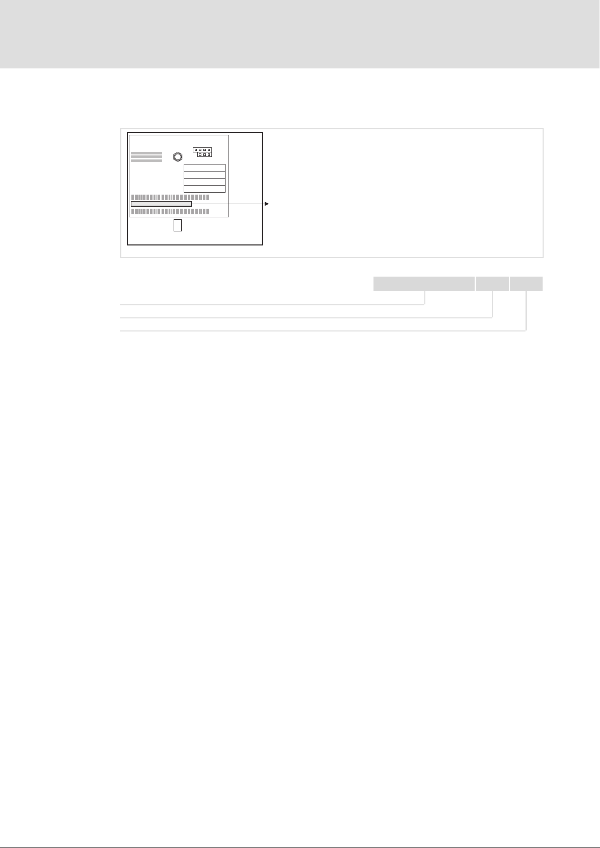
3.2 Identification
L
Type
Id.-No.
Prod.-No.
MAC-ID
Product description
Identification
3
E82AF000P0B201XX
Device series
Hardware version
Software version
2191EPL013
33.2191IB VA 10
EDSMF2191IB EN 2.0
13
Page 14

3
Product description
Product features
3.3 Product features
ƒ Powerful and real−time capable communication system for motion and general
applications. Real time Ethernet with the Ethernet POWERLINK V2 communication
profile.
ƒ Communication module for the AIF slot of the frequency inverters 8200 vector, 9300
vector and ECS servo system.
ƒ Support of the Ethernet POWERLINK slave functionality (controlled node).
ƒ Very short slave (Controlled Node) response times for optimal network performance.
ƒ Integrated Ethernet hub (double) for easily setting up line topologies without any
additional components.
ƒ External 24V supply for maintaining the POWERLINK communication in case the
device fails.
ƒ Use of max. 3 PDO crosslinks for master (managing node) or slave (controlled node)
to create systems with "distributed intelligence".
14
EDSMF2191IB EN 2.0
Page 15
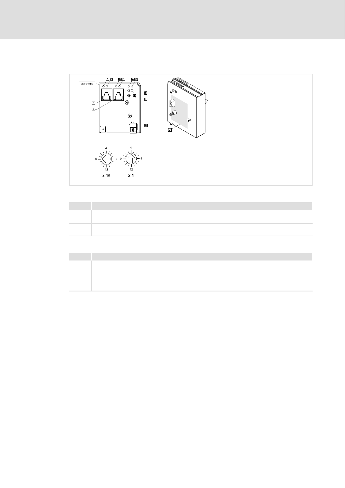
3.4 Connections and interfaces
Product description
Connections and interfaces
3
2191EPL001B
Connections
Pos. Description
Connection to external supply of the communication module
POWERLINK connection
Version: RJ45 socket according to IEC 60603−7
Version: Connector with screw connection, 2−pole
Switch
Pos. Description
Switches for addressing the nodes
l Left switch: Setting with factor 16
l Right switch: Setting with factor 1
The addition of both products results in the node address (node ID)
Node ID = 254 (the node ID is obtained from a DHCP server)
EDSMF2191IB EN 2.0
15
Page 16
3
Product description
Connections and interfaces
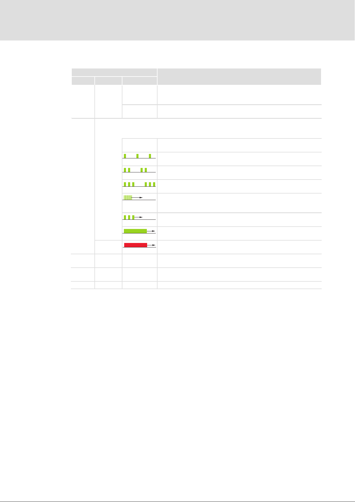
Displays
LED
Pos. Colour Condition
green
green
Red ERROR
Red On The red and green drive LED indicates the operating status of the
green blinking Depending on the connection state, the data is transmitted or received
yellow on Ethernet connection is available (LINK).
off The communication module is supplied with voltage, but has no
on The communication module is supplied with voltage and is connected to
The NMT state machine triggers the two−colored LED:
l Green: Display of status messages
l Red: Display of error messages
Off NMT_GS_OFF, NMT_GS_INITIALISATION,
Description
connection to the basic device (basic device is either switched off, in the
initialisation phase, or not available).
the standard device.
NMT_CS_NOT_ACTIVE / NMT_MS_NOT_ACTIVE
NMT_CS_PREOPERATIONAL_1 / NMT_MS_PREOPERATIONAL_1
(LED flashes once within a second.)
NMT_CS_PREOPERATIONAL_2 / NMT_MS_PREOPERATIONAL_2
(LED flashes twice within a second.)
NMT_CS_READY_TO_OPERATE / NMT_MS_READY_TO_OPERATE
(LED flashes three times within a second.)
NMT_CS_BASIC_ETHERNET
(LED is blinking with a frequency of 10 Hz or depending on the
connection state)
NMT_CS_STOPPED
(LED is blinking with a frequency of 2.5 Hz.)
NMT_CS_OPERATIONAL / NMT_MS_OPERATIONAL
(LED is lit permanently.)
(LED is lit permanently. An error has occurred.)
standard device (see documentation of the standard device).
(ACTIVITY).
16
EDSMF2191IB EN 2.0
Page 17

General data and operating conditions
4 Technical data
4.1 General data and operating conditions
Field Values
Order designation EMF2191IB
Communication profile Ethernet POWERLINK V2
Interface RJ45, Fast Ethernet Mode MII (according to IEEE 802.3)
Communication medium TP (100BaseTX, Cat5e)
Cable length max. 100 m between 2 nodes / hubs
Total extension Number of nodes x 100 m
Network topology Tree, star, line
Transmission mode Half duplex
Type of node Slave (CN, Controlled Node)
Node address Max. 239
Conformities, approvals l CE
l cUL
Baud rate 100 Mbps
Voltage supply External supply via separate power supply unit
+V =
−
24VDC(20.4 V − 0%... 28.8 V+ 0%)
I =
140 mA
Reference potential for external voltage supply
Technical data
4
Documentation for Lenze series of devices 8200 vector, 9300 and ECS
Here you can find the ambient conditions and the electromagnetic
compatibility (EMC) specifications applying to the communication module.
EDSMF2191IB EN 2.0
17
Page 18

4
Technical data
Protective insulation
4.2 Protective insulation
Danger!
Dangerous electrical voltage
If Lenze controllers are used on a phase earthed mains with a rated mains
voltage 400 V, protection against accidental contact is not ensured without
implementing external measures.
Possible consequences:
ƒ Death or serious injury
Protective measures:
ƒ If protection against accidental contact is required for the control terminals
of the controller and the connections of the plugged device modules, ...
– a double isolating distance must exist.
– the components to be connected must be provided with the second
isolating distance.
Insulation between bus and ... Type of insulation
(in accordance with EN 61800−5−1)
l Earth reference / PE Functional insulation
l With external supply Functional insulation
l Power stage
– 8200 vector Reinforced insulation
– 9300 servo inverter Reinforced insulation
– 93xx servo position controller Reinforced insulation
– 93xx servo register control Reinforced insulation
– 93xx servo cam profiler Reinforced insulation
– 9300 vector / Servo PLC Reinforced insulation
– ECS devices Reinforced insulation
l Control terminals
– 8200 vector Functional insulation
– 9300 servo inverter Basic insulation
– 93xx servo position controller Basic insulation
– 93xx servo register control Basic insulation
– 93xx servo cam profiler Basic insulation
– 9300 vector / Servo PLC Basic insulation
– ECS devices Basic insulation
18
EDSMF2191IB EN 2.0
Page 19

4.3 Data for POWERLINK communication
Field Values
Jitter synchronisation information approx. 1 s
Total cycle times Slave (CN): 1, 2, 3 60 ms
Buffer size
Frame size Max. asynchronous telegram size (MTU): 1518 bytes
SDO communication method UDP/IP
Number of RPDOs 3
RPDO user data per application (all
RPDOs)
Number of TPDOs 1
TPDO user data per application max. 32 objects with a total of max 64 bytes
Delay time
Tx−iso: max. 92 bytes (64 bytes of PDO user data)
Rx−iso: max. 328 bytes (300 bytes of PDO user data)
max. 32 objects with a total of max 64 bytes
T
− T
PReq
T
− T
SoA
Technical data
Data for POWERLINK communication
l The module can be operated with a minimum cycle of
1 ms.
l In multiplex mode, a minimum cycle of 200 sec is
supported if the data is accepted on the millisecond.
: 1900 ns
PRes
: 1900 ns
ASnd
4
EDSMF2191IB EN 2.0
19
Page 20

4
Technical data
Data for POWERLINK communication
Cycle time
4.3.1 Cycle time
The cycle time of the communication system is the time in which all process data between
the master (managing node) and the slaves (controlled nodes) are exchanged.
It depends on the data of the communication system and can be calculated as follows e. g.
for a baud rate of 500 kbps:
t
+ 3, 35 @ 10*3(n ) 48 ) 3 BK) ) 0, 24 L ) 0, 2
zykl
The following diagram shows the relation between cycle time and number of connected
fieldbus nodes. The given values refer to the connection of Lenze inverters (e.g. 82xx) with
48 bits (1 parameter data word + 2 process data words).
Cycle time
[ms]
12
t
cycl
n Sum of all data bits in the POWERLINK network
BK Number of bus terminals
L Length of the remote bus cable [km]
Cycle time [ms]
10
8
6
4
2
1
10
Number of nodes
Fig. 4−1 Relationship between cycle time and number of nodes
20
30 40
4.3.2 Processing time in the inverter
There are no interdependencies between parameter data and process data.
Processing times Parameter data Process data
Processing time inside the
inverter
Additional times outside
the inverter
l For controller−internal parameters
approx. 30 ms + a tolerance of 20 ms
l Some codes may have a longer
processing time (see documentation
of the inverter)
l Communication transfer times
l Communication processing times of the transmitting node
50 60
l There is no synchronisation between
the communication module and the
inverter.
l Times of 8200 vector/motec,
starttec: Approx 3 ms + a tolerance of
2 ms
l Times of 9300 / ECS: Approx. 2 ms +
a tolerance of 1 ms (each being
independent of the basic cycle time)
20
EDSMF2191IB EN 2.0
Page 21

4.4 Dimensions
All dimensions in mm
Technical data
Dimensions
4
2191EPL001B
EDSMF2191IB EN 2.0
21
Page 22

Installation5
5 Installation
Danger!
Inappropriate handling of the communication module and the standard device
can cause serious personal injury and material damage.
Observe the safety instructions and residual hazards described in the
documentation for the standard device.
Stop!
The device contains components that can be destroyed by electrostatic
discharge!
Before working on the device, the personnel must ensure that they are free of
electrostatic charge by using appropriate measures.
22
EDSMF2191IB EN 2.0
Page 23

5.1 Mechanical installation
Fig. 5−1 Attaching the communication module
ƒ Plug the communication module onto the standard device (here: 8200 vector).
ƒ Tighten the communication module to the standard device using the fixing screw in
order to ensure a good PE connection.
Installation
Mechanical installation
5
2102LEC014
Note!
For the internal supply of the communication module by the 8200 vector
frequency inverter the jumper has to be adjusted within the interface opening
(see illustration above).
Observe the notes ( 32).
EDSMF2191IB EN 2.0
23
Page 24

5
5.2 Electrical installation
5.2.1 Wiring according to EMC (CE−typical drive system)
Installation
Electrical installation
Wiring according to EMC (CE−typical drive system)
For wiring according to EMC requirements observe the following points:
Note!
ƒ Separate control cables/data lines from motor cables.
ƒ Connect the shields of control cables/data lines at both ends in the case of
digital signals.
ƒ Use an equalizing conductor with a cross−section of at least 16mm
(reference:PE) to avoid potential differences between the bus nodes.
ƒ Observe the other notes concerning EMC−compliant wiring given in the
documentation for the standard device.
Wiring procedure
2
1. Comply with bus topology, thus do not use stubs.
2. Observe notes and wiring instructions in the documents for the control system.
3. Only use cables that comply with the given specifications ( 30).
4. Observe notes for the voltage supply of the module ( 32).
24
EDSMF2191IB EN 2.0
Page 25

Installation
Electrical installation
Network topology
5
5.2.2 Network topology
IP routing
IT integration (NAT)
Access protection
Ethernet
Protected segment (machine system)
EPL
router
Hub
max. 100 m
max. 100 m
Hub
Detailed information on this topic can be found in the Ethernet POWERLINK
brochure "Real−time Industrial Ethernet is reality"
EDSMF2191IB EN 2.0
25
Page 26

5
Installation
Electrical installation
POWERLINK
5.2.3 POWERLINK
POWERLINK network segment
Note!
Standard Ethernet nodes are not permitted in the POWERLINK network
segment.
In order to use the real−time capability of the POWERLINK technology, the POWERLINK
nodes must be interconnected in a separate network segment.
In accordance with the POWERLINK rules, only the network master (managing node)
controls the access of the slaves (controlled nodes) to the network. The network master is
the only node that transmits autonomously. All other nodes (controlled nodes) only
transmit when they are entitled to transmit by the master.
Non−POWERLINK nodes (e.g. PCs) typically violate these rules by sending frames
independently of the master. These frames interfere with the cyclic frame exchange of the
POWERLINK nodes and prevent the real−time capability of the POWERLINK.
Connection to the standard Ethernet network
The connection to an external standard Ethernet network is carried out via an Ethernet
POWERLINK router.
These infrastructure component separates the network traffic in the POWERLINK network
segment from the one in the standard Ethernet. The handling of the frames depend on
their direction:
ƒ Standard Ethernet −−−> POWERLINK network segment
Only frames that are addressed to nodes in the POWERLINK network segment are
forwarded. The forwarding takes place in the asynchronous area of the POWERLINK
cycle.
ƒ POWERLINK network segment −−−> Standard Ethernet
Only asynchronous frames that are not addressed to nodes in the POWERLINK network
segment are forwarded.
26
EDSMF2191IB EN 2.0
Page 27

Installation
Electrical installation
POWERLINK
Topologies in the POWERLINK network segment
Note!
The use of class 1 hubs and switches inside the POWERLINK network segment
is not permitted.
Inside the segment only Ethernet hubs may be used as infrastructure elements. The hubs
must meet the requirements on class 2 repeaters acc. to IEEE 802.3u.
For this purpose, Lenze offers the dual hub integrated into the communication module and
the separate eight−fold hub, type E94AZCEH.
Class 1 hubs and switches are not permissible since they have considerably longer delay
times for the frame forwarding and a bigger jitter. Both sizes reduce the real−time
capability and dynamics.
The cable length between both nodes is limited to 100 m.
The topology rules (IEEE802.3u) required for controlling the collisions may be violated in
the POWERLINK network segment since according to the POWERLINK access order, frame
collisions are prevented. This enables a structure of lines and any hybrid forms between
star and line topology.
5
Recommended topology
For an easy configuration and due to many possible topology variants we recommend to
create networks according to the following rules:
1. Create slave groups with up to 10 nodes
2. Connect groups in star shape to the master (managing node).
3. For more than 2 groups: Use external 8−port hubs, e.g. Lenze hub E94AZCEH.
Exception: For maximally 2 groups, these are directly connected to the two ports of the
communication module.
Master
Hub
1. slave group
2. slave group
Fig. 5−2 Star topology for 1 to 2 slave groups
EDSMF2191IB EN 2.0
4. Connect slave groups to the master via one external hub each.
– For max. 7 slave groups one hub is sufficient.
– For more than 7 slave groups, use further hubs.
– The groups can be distributed on the hubs just as you like.
27
Page 28

5
5.2.4 Operation in the standard Ethernet
Installation
Electrical installation
Operation in the standard Ethernet
Note!
Operation in the standard Ethernet does not permit any real−time
communication.
The communication module can be operated in the standard Ethernet for a basic
parameter setting provided that the following applies:
1. Operation of the module in slave mode:
– Network address 239
– IP address: 192.168.100.<EPL address>
2. Real time operation must not be carried out.
3. No integration of a master (EPL address 240) into the standard Ethernet network.
More notes on wiring
ƒ Do not wire, if possible, more than 9nodes in succession in a network line.
28
EDSMF2191IB EN 2.0
Page 29

Installation
Electrical installation
POWERLINK connection
5
5.2.5 POWERLINK connection
You can use a standard Ethernet patch cable for connecting the communication module
to the fieldbus (see "Ethernet cable specifications" ( 30)).
Note!
Plug/remove the Ethernet cable plug in a straight manner (at right angles)
into/from the socket to make sure that the RJ45 socket will not be damaged.
Pin assignment
RJ45 socket PIN Signal
E94AYCXX004C
1 Tx +
2 Tx −
3 Rx +
4 −
5 −
6 Rx −
7 −
8 −
Tip!
The POWERLINK interfaces feature an auto MDIX function. This function
adjusts the polarity of the RJ45 interfaces so that a connection is established
irrespective of the polarity of the opposite POWERLINK interface, and
irrespective of the type of cable used (standard patch cable or crossover cable).
EDSMF2191IB EN 2.0
29
Page 30

5
Installation
Electrical installation
Specification of the Ethernet cable
5.2.6 Specification of the Ethernet cable
Note!
Only use cables complying with the below specifications.
Ethernet cable specifications
Ethernet standard Standard Ethernet (according to IEEE 802.3), 100base TX (fast Ethernet)
Cable type S/FTP (Screened Foiled Twisted Pair), ISO/IEC 11801 or EN 50173, CAT 5e
Damping 23.2 dB (at 100 MHz and per 100 m)
Crosstalk damping 24 dB (at 100 MHz and per 100 m)
Return loss 10 dB (per 100 m)
Surge impedance 100
Design of the Ethernet cable
Fig. 5−3 Design of the Ethernet cable (S/FTP, CAT 5e)
A Cable insulation
B Braid
C Foil shielding of the core pairs
TP1 ... TP4 Twisted core pairs 1 ... 4
E94YCEP016
30
EDSMF2191IB EN 2.0
Page 31

Colour code of Ethernet cable
Note!
Wiring and colour code are standardised in EIA/TIA 568A/568B.
You can use 4−pin Ethernet cables in accordance with the industrial standard.
The cable type only connects the assigned pins 1, 2, 3 and 6 with each other.
Installation
Electrical installation
Specification of the Ethernet cable
5
Fig. 5−4 Ethernet plug in accordance with EIA/TIA 568A/568B
Pair Pin Signal EIA/TIA 568A EIA/TIA 568B
3
2 3 Rx + White/orange White/green
1
2 6 Rx − Orange Green
4
1
2 Tx − Green Orange
4 Not assigned Blue Blue
5 Not assigned White/blue Blue/white
7 Not assigned White/brown White/brown
8 Not assigned Brown Brown
Tx + White/green White/orange
E94YCEI004A
EDSMF2191IB EN 2.0
31
Page 32

5
Installation
Electrical installation
Voltage supply
5.2.7 Voltage supply
Internal voltage supply
Note!
Internal voltage supply has been selected in the case of standard devices with
an extended AIF interface opening (e.g. front of 8200 vector). The area shown
on a grey background in the graphic marks the jumper position.
ƒ By default, this is not supplied internally in the standard device.
ƒ For internal voltage supply place the jumper on the position indicated
below.
In the case of all other device series (9300, ECS), voltage is always supplied
from the standard device.
(Only external voltage supply possible.)
Lenze setting
Internal voltage supply
External voltage supply
Note!
In the case of an external voltage supply and for greater distances between
the control cabinets, always use a separate power supply unit (SELV/PELV) that
is safely separated in accordance with EN 61800−5−1 in each control cabinet.
The external voltage supply of the communication module ...
ƒ is required if communication via the fieldbus is to be continued when the supply of
the device fails.
ƒ is provided via the 2−pin terminal strip with screw−type connection (24 V DC):
Terminal Description
+ External voltage supply
U = 24VDC(20.4 V − 0%... 28.8 V +0%)
I = 85 mA
− Reference potential for external voltage supply
ƒ The parameters of a standard device disconnected from the mains cannot be
accessed.
32
EDSMF2191IB EN 2.0
Page 33

Electrical installation
Terminal data
Area Values
Electrical connection Plug connector with screw connection
Possible connections
Tightening torque 0.5 ... 0.6 Nm (4.4 ... 5.3 lb−in)
Stripping length 6 mm
rigid:
flexible:
2
1.5 mm
without wire end ferrule
1.5 mm
with wire end ferrule, without plastic sleeve
1.5 mm
with wire end ferrule, with plastic sleeve
1.5 mm
(AWG 16)
2
(AWG 16)
2
(AWG 16)
2
(AWG 16)
Installation
Voltage supply
5
EDSMF2191IB EN 2.0
33
Page 34

6
Commissioning
Before switching on
6 Commissioning
During commissioning, system−dependent data as e.g. motor parameters, operating
parameters, responses and parameters for fieldbus communication are selected for the
controller.
In Lenze devices, this is done via codes. The codes are stored in numerically ascending order
in the Lenze controllers and in the plugged−in communication/function modules.
In addition to these configuration codes, there are codes for diagnosing and monitoring
the bus devices.
6.1 Before switching on
Stop!
Before switching on the standard device with the communication module for
the first time, check the entire wiring for completeness, short circuit and earth
fault.
34
EDSMF2191IB EN 2.0
Page 35

6.2 Setting the node address
Note!
ƒ Use different node addresses for several networked inverters.
The Lenze setting for the node address (node ID) has the value ’4’:
– link switch in position ’0’
– right switch in position ’4’
ƒ Switch the voltage supply of the inverter/communication module off and
on again to activate changed settings.
Commissioning
Setting the node address
6
E94YCEP001D
Fig. 6−1 Setting the node address
Each node has to be assigned to a unique address (node ID).
ƒ Valid address range for slave (controlled node): 1 ... 239
ƒ The corresponding IP address of the communication module results from the setting
of the two rotary switches.
IP address: 192.168.100.<Node ID>
(ValueNJLeftSwitchNj 16))(ValueNJRightSwitchNj) + NodeAddress
Example
ƒ Left rotary switch in position ’2’
ƒ Right rotary switch in position ’5’
(2 16))5 + 37
==> The node address is ’37’.
EDSMF2191IB EN 2.0
35
Page 36

6
6.3 Configuration via the "Automation Studio"
Commissioning
Configuration via the "Automation Studio"
The upgrade mechanism of the "Automation Studio" of the B & R company serves to establish an internet connection via which the necessary installation files are called.
After the upgrade, tick "display customised devices" in the hardware selection list to display the Lenze devices.
The following functions are available:
ƒ Adding Lenze devices to the hardware configuration
ƒ Setting node parameters (e.g. node ID)
ƒ I/O configuration (basic configuration settings of the controller)
ƒ Defining the I/O mapping (assignment of the process data objects of the controller
to the PLC objects)
The communication module is configured like a B & R device. The I/O configuration indicates the code which are compulsory for commissioning the inverter.
If further codes have to be written, library functions from the PLC project can be used. For
this purpose, you can find the "AsEPL" library in the "Library Manager". It provides the functions "EplSDOWrite" and "EplSDORead" which serve to read and write any parameters of
the device.
Indexing the Lenze codes
The index number is converted to a code as follows:
Conversion formula
Index (dec) Index (hex)
24575 − Lenze code 0x5FFF − (Lenze code)
Example of C0001 (operating mode):
Index (dec) Index (hex)
24575 − 1 = 24574 0x5FFF − 1 = 0x5FFE
Further information on the "Automation Studio" functions can be found in the
corresponding documentation.
36
EDSMF2191IB EN 2.0
Page 37

6.4 Initial switch−on
Switch on the inverter and check whether it is ready for operation using the diagnostic
LEDs at the front of the communication module.
ƒ Red diagnostic LEDs must not be on.
ƒ The following signalling should be visible:
LED
Pos. Colour Condition
green on The communication module is supplied with voltage and is connected to
green
green blinking Depending on the connection state, the data is transmitted or received
yellow on Ethernet connection is available (LINK).
Commissioning
Description
the standard device.
The NMT state machine triggers the two−colored LED:
l Green: Display of status messages
l Red: Display of error messages
NMT_CS_BASIC_ETHERNET
(LED is blinking with a frequency of 10 Hz or depending on the
connection state)
NMT_CS_OPERATIONAL / NMT_MS_OPERATIONAL
(LED is lit permanently.)
(ACTIVITY).
6
Initial switch−on
EDSMF2191IB EN 2.0
37
Page 38

Diagnostics7
7 Diagnostics
The LEDs on the front are provided to the communication module for the purpose of fault
diagnostics.
Displays
LED
Pos. Colour Condition
green
green
Red ERROR
Red On The red and green drive LED indicates the operating status of the
green blinking Depending on the connection state, the data is transmitted or received
yellow on Ethernet connection is available (LINK).
Description
off The communication module is supplied with voltage, but has no
connection to the basic device (basic device is either switched off, in the
initialisation phase, or not available).
on The communication module is supplied with voltage and is connected to
the standard device.
The NMT state machine triggers the two−colored LED:
l Green: Display of status messages
l Red: Display of error messages
Off NMT_GS_OFF, NMT_GS_INITIALISATION,
NMT_CS_NOT_ACTIVE / NMT_MS_NOT_ACTIVE
NMT_CS_PREOPERATIONAL_1 / NMT_MS_PREOPERATIONAL_1
(LED flashes once within a second.)
NMT_CS_PREOPERATIONAL_2 / NMT_MS_PREOPERATIONAL_2
(LED flashes twice within a second.)
NMT_CS_READY_TO_OPERATE / NMT_MS_READY_TO_OPERATE
(LED flashes three times within a second.)
NMT_CS_BASIC_ETHERNET
(LED is blinking with a frequency of 10 Hz or depending on the
connection state)
NMT_CS_STOPPED
(LED is blinking with a frequency of 2.5 Hz.)
NMT_CS_OPERATIONAL / NMT_MS_OPERATIONAL
(LED is lit permanently.)
(LED is lit permanently. An error has occurred.)
standard device (see documentation of the standard device).
(ACTIVITY).
38
EDSMF2191IB EN 2.0
Page 39

8 Appendix
8.1 Index table
Overview
The following objects specified by the Ethernet POWERLINK communication profile are
supported.
Tip!
The Ethernet POWERLINK specification contains details on the POWERLINK
communication profile and can be obtained from the Ethernet POWERLINK
Standardisation Group (EPSG):
http://www.ethernet−powerlink.org
Appendix
Index table
8
EPL index Subindex Index name More information
0x1000 NMT_DeviceType_U32 42
0x1001 ERR_ErrorRegister_U8 42
0x1003 ERR_History_ADOM −
0x1006 NMT_CycleLen_U32 42
0x1008 NMT_ManufactDevName_VS −
0x1009 NMT_ManufactHwVers_VS −
0x100A NMT_ManufactSwVers_VS −
0x1010 NMT_StoreParam_REC −
0x1011 NMT_RestoreDefParam_REC −
0x1018 1 ... 4 NMT_IdentityObject_REC 42
0x1020 CFM_VerifyConfiguration_REC −
0x1030 1 ... 9 NMT_InterfaceGroup_0h_REC 43
0x1101 1 Dia_NMTTelegramCount_REC 43
0x1400 1 ... 2 PDO_RxCommParam_00h_REC 43
0x1401 1 ... 2 PDO_RxCommParam_01h_REC 44
0x1402 1 ... 2 PDO_RxCommParam_02h_REC 44
0x1600 1 ... 20 PDO_RxMappParam_00h_REC 44
0x1601 1 ... 20 PDO_RxMappParam_01h_REC 45
0x1602 1 ... 20 PDO_RxMappParam_02h_REC 45
0x1800 1 ... 2 PDO_TxCommParam_00h_REC −
0x1A00 1 ... 20 PDO_TxMappParam_00h_REC 46
0x1C0A DLL_CNCollision_REC 46
0x1C0B DLL_CNLossSoC_REC 46
0x1C0C DLL_CNLossSoA_REC −
0x1C0D DLL_CNLossPReq_REC −
0x1C0E DLL_CNSoCJitter_REC −
0x1C0F DLL_CNCRCError_REC 47
0x1C10 DLL_CNLossOfLinkCum_U32 47
0x1C13 DLL_CNSoCJitterRange_U32 −
EDSMF2191IB EN 2.0
39
Page 40

8
Appendix
Index table
More informationIndex nameSubindexEPL index
0x1C14 DLL_LossOfFrameTolerance_U32 −
0x1E40 1 ... 5 NWL_IpAddrTable_0h_REC 48
0x1E4A 1 ... 3 NWL_IpGroup_REC −
0x1F50 PDL_DownloadProgData_ADOM −
0x1F51 PDL_ProgCtrl_AU8 −
0x1F52 PDL_LocVerApplSw_REC −
0x1F81 1 ... 64 NMT_NodeAssignment_AU32 49
0x1F82 NMT_FeatureFlags_U32 50
0x1F83 NMT_EPLVers_U8 50
0x1F8C NMT_CurrState_U8 51
0x1F8D 1 ... 64 NMT_MNPResPayloadList_AU32 51
0x1F93 1 ... 2 NMT_EPLNodeID_REC 51
0x1F98 1 ... 9 NMT_CycleTiming_REC −
0x1F99 NMT_CNBasicEthernetTimeout_U32 51
0x1F9A NMT_HostName_VSTR 52
0x1F9E NMT_ResetCmd_U8 52
40
EDSMF2191IB EN 2.0
Page 41

Appendix
Index table
How to read the index table
Model of an index table
Index Name
Subcode Lenze Values Data type
Access:
Meaning
Header Meaning
Index Number of the Ethernet POWERLINK index I−xxxx
Name Display text
8
Leading
columns
Subcode Number of the subcode
Lenze
Values
Data type
Footer Meaning
Access ro: The parameter can only be read (display code)
Meaning
Lenze setting ("Default" setting) of the code
à Display code
The code cannot be configured.
Minimum value [smallest increment/unit] Maximum value
In case of a display code the displayed values are specified.
l BITFIELD_8
l BITFIELD_32
l U8 8 bit value without sign
l U16 16 bit value without sign
l U32 32 bit value without sign
l U64 64 bit value without sign
l VS Visible String, string with specified length
rw: The parameter can be changed
EDSMF2191IB EN 2.0
41
Page 42

8
Appendix
Index table
I−1000:
EPL device type
Index
0x1000
Subcode Lenze Values Data type
−
EPL name
NMT_DeviceType_U32
U32
Access: ro
The object displays the device type of the node.
I−1001:
EPL error register
Index
0x1001
Subcode Lenze Values Data type
−
EPL name
ERR_ErrorRegister_U8
U8
Access: ro
The object contains currently pending errors arranged according to error classes. The bits
of the error register have the following meaning:
Bit Description
0 Generic error, signals an existing error message in the CN which can be read out via StatusResponse
1 Amperage
2 Voltage
3 Temperature
4 Communication error
5 Device profile−related error
6 Reserved (0)
7 Manufacturer−specific error
I−1006:
EPL cycle time
Index
0x1006
Subcode Lenze Values Data type
−11 ... [1 ms] ... 20 U32
EPL name
NMT_CycleLen_U32
Access: rw
The object contains the length of the EPL cycle in [s].
I−1018:
EPL identity object
Index
0x1018
Subcode Lenze Values Data type
1: VendorId_U32 0x59
2: ProductCode_U32 2191
3: RevisionNo_U32 0x00000000
4: SerialNo_U32
EPL name
NMT_IdentityObject_REC
U32
Access: ro
The object contains identification information on the communication module.
42
EDSMF2191IB EN 2.0
Page 43

I−1030:
EPL MAC address
Appendix
Index table
8
Index
0x1030
Subcode Lenze Values Data type
1: InterfaceIndex_U16
2: InterfaceDescription_VSTR EMF2191IB_1 VSTR
3: InterfaceType_U8 6 U8
4: InterfaceMtu_U32 1500 U32
5: InterfacePhysAddress_OSTR "00:0A:86:84:xx:xx" OSTR
6: InterfaceName_VSTR "IF1" VSTR
7: InterfaceOperStatus_U8 1 U8
EPL name
NMT_InterfaceGroup_0h_REC
0 U16
Access: ro for subcodes 1, 2, 3, 4, 5
and 7
Access: rw for subcode 6
The object contains information on the Ethernet interface. The subcode 5 contains the
MAC address. When the communication module is produced, the MAC address is assigned
unequivocally worldwide and provides addressing on the lowest level.
I−1101:
EPL telegram counter
Index
0x1101
Subcode Lenze Values Data type
1: IsochrCyc_U32 − − U32
EPL name
DIA_NMTTelegrCount_REC
Access: ro
Subcode 1 of the object contains a counter for POWERLINK cycles. The counter is started
with each power−on of the node at 0. An overflow occurs at 4.294.967.295.
I−1400:
EPL address : RPDO
Index
0x1400
Subcode Lenze Values Data type
100, 1 ... 240, 253, 254 U8
EPL name
PDO_RxCommParam_XXh_REC.NodeID_U8
Access: rw
Subcode 1 of the object contains the node address (node ID) of the transmitting node for
the PDO channel (n+1).
Values > ’0’ describe the origin of a PRes telegram. The value ’0’ is reserved for "PReq"
(cannot be used in systems with a Lenze Servo Drive 9400 as managing node).
The value is only valid if the corresponding object 0x160x has a value > ’0’.
EDSMF2191IB EN 2.0
43
Page 44

8
Appendix
Index table
I−1401:
EPL address : RPDO
Index
0x1401
Subcode Lenze Values Data type
100, 1 ... 240, 253, 254 U8
EPL name
PDO_RxCommParam_XXh_REC.NodeID_U8
Access: rw
Subcode 1 of the object contains the node address (node ID) of the transmitting node for
the PDO channel (n+1).
Values > ’0’ describe the origin of a PRes telegram. The value ’0’ is reserved for "PReq"
(cannot be used in systems with a Lenze Servo Drive 9400 as managing node).
The value is only valid if the corresponding object 0x160x has a value > ’0’.
I−1402:
EPL address : RPDO
Index
0x1402
Subcode Lenze Values Data type
100, 1 ... 240, 253, 254 U8
EPL name
PDO_RxCommParam_XXh_REC.NodeID_U8
Access: rw
Subcode 1 of the object contains the node address (node ID) of the transmitting node for
the PDO channel (n+1).
Values > ’0’ describe the origin of a PRes telegram. The value ’0’ is reserved for "PReq"
(cannot be used in systems with a Lenze Servo Drive 9400 as managing node).
The value is only valid if the corresponding object 0x160x has a value > ’0’.
I−1600:
EPL number of RPDO
Index
0x1600
Subcode Lenze Values Data type
000, 1 ... 32 U64
EPL name
PDO_RxMappParam_xxh_AU64.NumberOfEntries
Access: rw
The object describes the number of valid mapping entries for the PDO channel (n+1).
The value ’0’ inhibits the PDO channel. The sum of all mapping entries enabled via the
objects 0x160x must not exceed the value ’64’.
44
EDSMF2191IB EN 2.0
Page 45

I−1601:
EPL number of RPDO
Appendix
Index table
8
Index
0x1601
Subcode Lenze Values Data type
000, 1 ... 32 U64
EPL name
PDO_RxMappParam_xxh_AU64.NumberOfEntries
Access: rw
The object describes the number of valid mapping entries for the PDO channel (n+1).
The value ’0’ inhibits the PDO channel. The sum of all mapping entries enabled via the
objects 0x160x must not exceed the value ’64’.
I−1602:
EPL number of RPDO
Index
0x1602
Subcode Lenze Values Data type
000, 1 ... 32 U64
EPL name
PDO_RxMappParam_xxh_AU64.NumberOfEntries
Access: rw
The object describes the number of valid mapping entries for the PDO channel (n+1).
The value ’0’ inhibits the PDO channel. The sum of all mapping entries enabled via the
objects 0x160x must not exceed the value ’64’.
EDSMF2191IB EN 2.0
45
Page 46

8
Appendix
Index table
I−1A00:
EPL TPDO
Index
0x1A00
Subcode Lenze Values Data type
1 ... 32: ObjectMapping − see below U64
EPL name
PDO_TxMappParam_00h_AU64
Access: rw
The object describes the mapping for the TPDO channel. Subcode 0 describes the number
of valid mapping object entries. Subcodes 1 to 32 describe the mapping of the individual
objects.
The entry is structured as follows:
Byte Name Description
0, 1 Index EPL index of the mapped object
2 Subindex Subindex
3 Reserved
4, 5 Offset Offset, calculated from the start of the PDO user data [bits]
6, 7 Length Length of the mapped object [bits]
I−1C0A:
EPL CN: Telegr. collisions
Index
0x1C0A
Subcode Lenze Values Data type
1: CumulativeCnt_U32 − − U32
EPL name
DLL_CNCollision_REC
Access: ro
The object indicates the number of Ethernet collisions detected by the slave (controlled
node).
Each event is counted. Every single event is followed by an error message. No threshold
value management is implemented.
I−1C0B:
EPL CN: Loss of synchr.
Index
0x1C0B
Subcode Lenze Values Data type
1: CumulativeCnt_U32 − −
2: ThresholdCnt_U32 − −
3: Threshold_U32 1 0, 1, 2 etc.
EPL name
DLL_CNCollision_REC
U32
Access: see below
The slave (controlled node) expects SoC frames in time intervals which correspond to the
cycle time.
The object indicates the error counters for missing SoC frames.
46
EDSMF2191IB EN 2.0
Page 47

I−1C0F:
EPL CN: Frame error (CRC)
Appendix
Index table
8
Index
0x1C0F
Subcode Lenze Values Data type
1: CumulativeCnt_U32 − − U32
2: ThresholdCnt_U32 0 0, 1, 2, 3 ... U32
3: Threshold_U32 0 0, 1, 2, 3 ... U32
EPL name
DLL_CNCRCError_REC
Access:
Subcode 3: rw , otherwise ro
The object indicates the number of frame checksum errors detected by the slave
(controlled node).
I−1C10:
EPL CN: Link interruptions
Index
0x1C10
Subcode Lenze Values Data type
−−− U32
EPL name
DLL_CNLossOfLinkCum_U32
Access: ro
The object indicates the counter of the slave (controlled node) for Ethernet connection
interruptions.
Each event is counted. Every single event is followed by an error message. No threshold
value management is implemented.
EDSMF2191IB EN 2.0
47
Page 48

8
Appendix
Index table
I−1E40:
EPL IP address
Index
0x1E40
Subcode Lenze Values Data type
2
3
5 0xC0A864FE −
ƒ Subcode 2:
EPL name
NWL_IpAddrTable_0h_REC.Addr_IPAD
−
−
U32
Access: ro
The subcode contains the IP address of the communication module. It is derived
according to the following rule from the node address (node ID, I−1F93):
192.168.100.<I−1F93>
ƒ Subcode 3:
The subcode contains the IP subnet mask which limits the IP address range that can be
addressed directly (i.e. without using a gateway in the EPL segment of the routers). In
an EPL segment, the subnet mask is permanently assigned to the value
’255.255.255.0’ (0xFFFFFF00).
ƒ Subcode 5:
The subcode contains the IP address of the EPL router via which the EPL segment is
connected to the higher−level network.
The standard entry corresponds to the standard router address of the POWERLINK
specification:
192.168.100.254
Permissible entries replace the lowest−order byte of the standard entry with the EPL
address of the node which has the function of a router.
48
EDSMF2191IB EN 2.0
Page 49

I−1F81:
EPL node declaration CN
Appendix
Index table
8
Index
0x1F81
Subcode Lenze Values Data type
EPL name
NMT_NodeAssignment_AU32
see table U32
Access: rw
The object describes the slave (controlled node) and its properties.
The describing bit field has the following structure:
Relevance
Bit
0 (LSB) þ þ 0, 1 0 Node with this ID does not exist
1 þ þ 0, 1 0 Node with this ID is no CN
2 þ ¨ 1 0
3 þ þ 1 0 optional CN.
4 þ ¨ 0
5 þ ¨ 0 0 Application SW version verification is not required
6 þ ¨ 0, 1 0 Automatic application SW update is not allowed
7 − − 0 − Reserved
8 þ þ 0, 1 0 Isochronously accessed CN.
9 þ þ 0 0 Continuously accessed CN
10 ... 30 − − 0 − Reserved
31 (MSB) þ þ 0, 1 0 Bit 0 .. 30 inhibited
*)
Not permissible for Servo Drives 9400
MN CN
Lenze Value Description
1 Node with this ID exists
1 Node with this ID is a CN
*)
starting CNs are not automatically booted
1 starting CNs are automatically booted
1 obligatory CN.
0
1
1
1 Automatic application SW update is allowed
1 AsyncOnly CN, bit 9 irrelevant
1
1 Bit 0 .. 30 enabled
CN can be reset independently of the current state using the
NMTResetCommunication command
*)
CN must not be reset when being in the NMT_CS_OPERATIONAL state
*)
Application SW version verification is required
*)
Multiplex CN
EDSMF2191IB EN 2.0
49
Page 50

8
Appendix
Index table
I−1F82:
EPL feature flags
Index
0x1F82
Subcode Lenze Values Data type
−
EPL name
NMT_FeatureFlags_U32
U32
Access: ro
The object indicates the POWERLINK functions implemented by the slave (controlled
node).
The describing bit field has the following structure:
Relevance
Bit
0 ¨ þ Isochronous access is allowed Only AsyncOnly access
1 þ þ SDO via UDP/IP No SDO by UDP/IP
2 þ þ SDO via EPL ASnd
3 þ þ SDO integrated in PDO No SDO integrated in PDO
4 þ þ Support NMT Info Services No NMT Info Services
5 þ þ Support of extended NMT State Commands No extended NMT State Commands
6 þ þ Support of dynamic PDO mapping No dynamic PDO mapping
7 þ ¨ NMT services via UDP/IP No NMT services via UDP/IP
8 þ þ Configuration manager function No configuration manager function
9 þ þ Isochronous multiplex access is possible Only isochronous cyclic access is allowed
10 ¨ þ Address assignment via SW No address assignment via SW
11 þ ¨ Support of basic Ethernet mode of the master No support of basic Ethernet mode of the master
12 þ þ Device can be used as Powerlink to standard Ethernet
13 þ þ Device can be used as Powerlink to fieldbus router Device does not support any Powerlink to fieldbus
14 ... 31 − − Reserved (these bits are assigned to FALSE) −
MN CN
TRUE FALSE
(only MN for Servo Drives 9400)
router
No SDO via EPL ASnd
(only CN for Servo Drives 9400)
Device does not support any Powerlink to standard
Ethernet function
router function
I−1F83:
EPL version
Index
0x1F83
Subcode Lenze Values Data type
−
EPL name
NMT_EPLVers_U8
0x20 U8
Access: ro
The object describes the version of the Ethernet POWERLINK communication profile
implemented by the communication module.
The higher−order nibble describes the major version, the lower order nibble describes the
minor version. The implemented value corresponds to the EPL version 2.0.
50
EDSMF2191IB EN 2.0
Page 51

I−1F8C:
EPL communication status
Appendix
Index table
8
Index
0x1F8C
Subcode Lenze Values Data type
−
EPL name
NMT_CurrNMTState_U8
see table
Access: ro
The object contains the current NMT state.
I−1F8D:
EPL CN: Max. user data PRes RPDO
Index
0x1F8D
Subcode Lenze Values Data type
1 ... 100 36 bytes see description, unit: Byte U16
EPL name
NMT_PResPayloadList_AU16
Access: rw
This object defines the reserved user data length of the PRes frames.
Each subcode corresponds to a node with the same node ID. The node must have been
enabled via the object 0x1F81. The subcode describes the received PRes frames.
The value must be within the range of 36 ... 1490 bytes. The values are limit values for the
total sizes of the PDO mappings to be defined for received PRes frames.
I−1F93:
EPL device address
Index
0x1F93
Subcode Lenze Values Data type
−−1 .. 239 U8
EPL name
NMT_EPLNodeID_REC.NodeID_U8
Access: ro
The object contains the currently valid node address (node ID).
I−1F99:
EPL CN: Max. MN detection time
Index
0x1F99
Subcode Lenze Values Data type
− 5000000 s 0 ... 50000000 s U32
EPL name
NMT_CNBasicEthernetTimeout_U32
Access: rw
The object contains a time interval for a booting slave (controlled node) for detecting a
master (managing node). If a booting slave (controlled node) detects a master (managing
node) during the interval, it changes to NMT_CS_PREOPERATIONAL_1. If not, it changes to
"Basic Ethernet Mode".
EDSMF2191IB EN 2.0
51
Page 52

8
Appendix
Index table
I−1F9A:
EPL host name
Index
0x1F9A
Subcode Lenze Values Data type
−−see "naming convention" VS15
EPL name
NMT_Hostname_VSTR
Access: rw
The object contains a DNS−compatible device name. The length is limited to 15 characters.
Naming convention:
ƒ The device name ...
– starts with a letter;
– ends with a letter or a digit.
ƒ The device name consists of ...
– letters (A .. Z), upper or lower case,
– digits (0 .. 9),
– hyphen (−).
Note!
The device name must be unambiguous within the network domain.
I−1F9E:
EPL reset command
Index
0x1F9E
Subcode Lenze Values Data type
− see table U8
EPL name
NMT_ResetCmd_U8
Access: wo
The object initiates a reset of the node. The following reset commands are available:
Command Value Status transition
NMTInvalidService 0xFF (255) no function (default)
NMTResetNode 0x28 (40) NMT_GS_RESET_APPLICATION
NMTResetCommunication 0x29 (41) NMT_GS_RESET_COMMUNICATION
NMTResetConfiguration 0x2A (42) NMT_GS_RESET_CONFIGURATION
NMTSwReset 0x2B (43) NMT_GS_INITIALISING
When the reset has been executed, the object is automatically set to "NMTInvalidService".
Stop!
A reset command on a single node in the network can cause cycle and
monitoring errors.
52
EDSMF2191IB EN 2.0
Page 53

9 Index
Index 9
A
Address settings, 35
Application as directed, 12
Automation Studio, configuration, 36
B
Baud rate, 17
C
Cable specification, 30
CE−typical drive system, 24
Colour code of Ethernet cable, 31
Commissioning, 34
− Initial switch−on, 37
Communication medium, 17
Communication profile, 17
Configuration via the "Automation Studio", 36
Connection to the standard Ethernet, 26
Connections, 15
Cycle time, 20
D
Data for POWERLINK communication, 19
Definition of notes used, 9
Definitions, 8
Design of the Ethernet cable, 30
Device protection, 11, 22
Diagnostics, 38
E
Electrical installation, 24
EPL index
− 1C0B, 46
− I−1000, 42
− I−1001, 42
− I−1006, 42
− I−1018, 42
− I−1030, 43
− I−1101, 43
− I−1400, 43
− I−1401, 44
− I−1402, 44
− I−1600, 44
− I−1601, 45
− I−1602, 45
− I−1A00, 46
− I−1C0A, 46
− I−1C0F, 47
− I−1C10, 47
− I−1E40, 48
− I−1F81, 49
− I−1F82, 50
− I−1F83, 50
− I−1F8C, 51
− I−1F8D, 51
− I−1F93, 51
− I−1F99, 51
− I−1F9A, 52
− I−1F9E, 52
Ethernet cable specification, 30
Ethernet cable, colour code , 31
Ethernet cable, design, 30
Ethernet connection, 29
External voltage supply, 32
EDSMF2191IB EN 2.0
53
Page 54

Index9
H
Hardware version, type code, 13
I
I−1000: EPL device type, 42
I−1001: EPL error register, 42
I−1006: EPL cycle time, 42
I−1018: EPL identity object, 42
I−1030: EPL MAC address, 43
I−1101: EPL telegram counter, 43
I−1400: EPL address RPDO, 43
I−1401: EPL address RPDO, 44
I−1402: EPL address RPDO, 44
I−1600: EPL number of RPDO, 44
I−1601: EPL number of RPDO, 45
I−1602: EPL number of RPDO, 45
I−1A00: EPL TPDO, 46
I−1C0A: EPL CN: Telegr. collisions, 46
I−1C0B: EPL CN: Loss of synchr., 46
I−1C0F: EPL CN: Frame error (CRC), 47
I−1C10: EPL CN: Link interruptions, 47
I−1E40: EPL IP address, 48
I−1F81: EPL node declaration CN, 49
I−1F82: EPL feature flags, 50
I−1F83: EPL version, 50
I−1F8C: EPL communication status, 51
I−1F8D: EPL CN: Max. user data PRes RPDO, 51
I−1F93: EPL device address, 51
I−1F99: EPL CN: Max. MN detection time, 51
I−1F9A: EPL host name, 52
I−1F9E: EPL reset command, 52
Identification, 13
Indexing the Lenze codes, 36
Initial switch−on, 37
Installation, 22
− electrical, 24
− mechanical, 23
Interface, 17
Interfaces, 15
Internal voltage supply, 32
M
Mechanical installation, 23
N
Nameplate, 13
Network segment, 26
Network topology, 17
Notes, definition, 9
O
Operation in the standard Ethernet, 28
Order designation, 17
P
POWERLINK communication (technical data), 19
POWERLINK connection, 29
POWERLINK network segment, 26
Processing time, 20
Product description, 12
− application as directed, 12
Product features, 14
Protection of persons, 11
Protective insulation, 18
R
Residual hazards, 11
S
Safety instructions, 10
− application as directed, 12
− definition, 9
− device− and application−specific, 11
− layout, 9
Setting the node address, 35
Software version, type code, 13
Specification of the Ethernet cable, 30
Standard Ethernet connection, 26
Standard Ethernet operation, 28
Switch on, initial, 37
54
EDSMF2191IB EN 2.0
Page 55

Index 9
T
Technical data, 17
Terminal data, 33
Topologies in the POWERLINK network segment, 27
Transmission mode, 17
Type code, 13
− finding, 13
V
Validity of the documentation, 5
Voltage supply, 32
− internal, 32
Voltage supply: external, 32
W
Wiring according to EMC, 24
EDSMF2191IB EN 2.0
55
Page 56

F
(
Ê
ü
© 09/2013
Lenze Automation GmbH
Hans−Lenze−Str. 1
D−31855 Aerzen
Germany
+49(0)51 54 /82−0
+49(0)51 54 /82 − 28 00
Lenze@Lenze.de
www.Lenze.com
Service Lenze Service GmbH
Breslauer Straße 3
D−32699 Extertal
Germany
(
Ê
008000/ 2446877 (24 h helpline)
+49(0)5154/ 82−11 12
Service@Lenze.de
EDSMF2191IB § .M\} § EN § 2.0 § TD17
10987654321
 Loading...