

Page 1
EDKMF2181
.AEl
L-force Communication
Montageanleitung
Mounting Instructions
Instructions de montage
Instrucciones para el montaje
Istruzioni per il montaggio
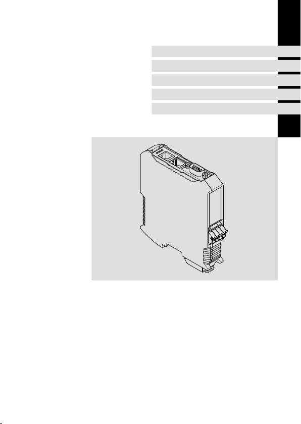
ModemCAN
Ä.AElä
EMF2181IB
Kommunikationsbaugruppe
Communication module
Module de communication
Módulo de comunicación
Modulo di comunicazione
Page 2

Lesen Sie zuerst diese Anleitung, bevor Sie mit den Arbeiten beginnen!
Beachten Sie die enthaltenen Sicherheitshinweise.
Please read these instructions before you start working!
Follow the enclosed safety instructions.
Veuillez lire attentivement cette documentation avant toute action !
Les consignes de sécurité doivent impérativement être respectées.
Lea las instrucciones antes de empezar a trabajar.
Observe las instrucciones de seguridad indicadas.
Prima di usare l’apparecchiatura, leggere le istruzioni contenute in questo
manuale.
Osservare le note di sicurezza.
Page 3
2181FEW0 01D
E82ZAFX028
Page 4

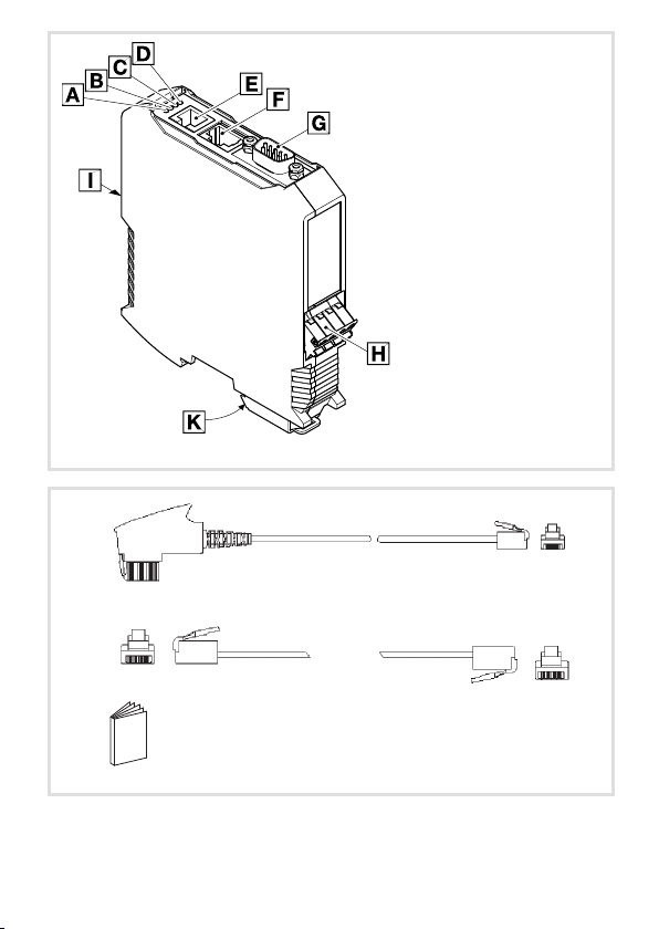
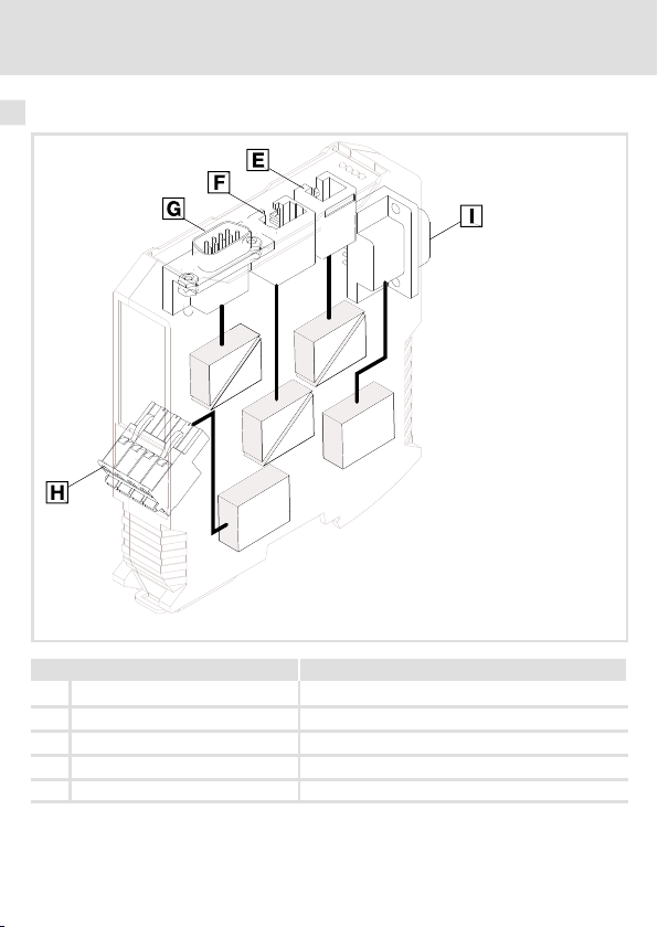
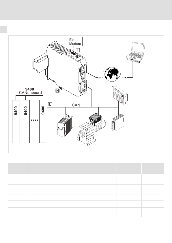
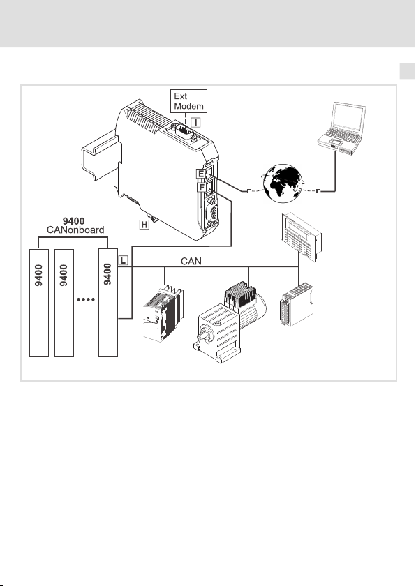
Legende zur Abbildung auf der Ausklappseite
Pos. Beschreibung Ausführliche
Information
LED-Statusanzeigen zur Diagnose 32
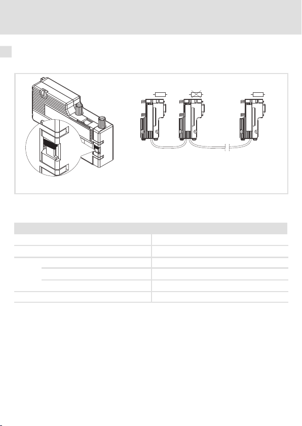
Telefon-Anschluss
Buchse RJ11
Diagnose-Anschluss
Buchse RJ69
CAN-Anschluss
Buchse RS232 (male)
Anschluss für Spannungsversorgung
4-polige Steckerleiste mit Federkraftanschluss
Anschluss für externes Modem
Buchse RS232 (male)
PE-Anschluss
Die gesteckte Kommunikationsbaugruppe ist automatisch mit der Hutschiene verbunden.
Die Hutschiene muss mit PE verbunden sein!
1 TAE-Anschlusskabel (TAE-N - RJ11) 28
1 Modular-Anschlusskabel (RJ11 - RJ11) 28
Montageanleitung
0Abb.0Tab. 0
27
26
23
30
29
4
EDKMF2181 DE/EN/FR/ES/IT 3.0
Page 5

Inhalt i
1 Über diese Dokumentation 6. . . . . . . . . . . . . . . . . . . . . . . . . . . . . . . . . . . . . . . . . .
Verwendete Konventionen 7. . . . . . . . . . . . . . . . . . . . . . . . . . . . . . . . . . . . . . . . . .
Verwendete Hinweise 8. . . . . . . . . . . . . . . . . . . . . . . . . . . . . . . . . . . . . . . . . . . . . . .
2 Sicherheitshinweise 10. . . . . . . . . . . . . . . . . . . . . . . . . . . . . . . . . . . . . . . . . . . . . . . .
3 Produktbeschreibung 11. . . . . . . . . . . . . . . . . . . . . . . . . . . . . . . . . . . . . . . . . . . . . . .
Funktion 11. . . . . . . . . . . . . . . . . . . . . . . . . . . . . . . . . . . . . . . . . . . . . . . . . . . . . . . . . .
Bestimmungsgemäße Verwendung 11. . . . . . . . . . . . . . . . . . . . . . . . . . . . . . . . . . .
Lieferumfang 11. . . . . . . . . . . . . . . . . . . . . . . . . . . . . . . . . . . . . . . . . . . . . . . . . . . . . .
Identifikation 12. . . . . . . . . . . . . . . . . . . . . . . . . . . . . . . . . . . . . . . . . . . . . . . . . . . . . .
4 Technische Daten 13. . . . . . . . . . . . . . . . . . . . . . . . . . . . . . . . . . . . . . . . . . . . . . . . . .
Allgemeine Daten und Einsatzbedingungen 13. . . . . . . . . . . . . . . . . . . . . . . . . . .
Schutzisolierung 14. . . . . . . . . . . . . . . . . . . . . . . . . . . . . . . . . . . . . . . . . . . . . . . . . . .
Abmessungen 15. . . . . . . . . . . . . . . . . . . . . . . . . . . . . . . . . . . . . . . . . . . . . . . . . . . . .
5 Mechanische Installation 16. . . . . . . . . . . . . . . . . . . . . . . . . . . . . . . . . . . . . . . . . . . .
6 Elektrische Installation 18. . . . . . . . . . . . . . . . . . . . . . . . . . . . . . . . . . . . . . . . . . . . . .
Kommunikation über CAN 18. . . . . . . . . . . . . . . . . . . . . . . . . . . . . . . . . . . . . . . . . .
Kommunikation über die Diagnoseschnittstelle (Servo Drives 9400) 19. . . . . . . .
Umgang mit Steckerleisten 21. . . . . . . . . . . . . . . . . . . . . . . . . . . . . . . . . . . . . . . . . .
EMV-gerechte Verdrahtung 22. . . . . . . . . . . . . . . . . . . . . . . . . . . . . . . . . . . . . . . . . .
Systembus (CAN) anschließen 23. . . . . . . . . . . . . . . . . . . . . . . . . . . . . . . . . . . . . . . .
Diagnoseschnittstelle 26. . . . . . . . . . . . . . . . . . . . . . . . . . . . . . . . . . . . . . . . . . . . . .
Telefonverbindung 27. . . . . . . . . . . . . . . . . . . . . . . . . . . . . . . . . . . . . . . . . . . . . . . .
Anschluss für externes Modem 29. . . . . . . . . . . . . . . . . . . . . . . . . . . . . . . . . . . . . .
Spannungsversorgung 30. . . . . . . . . . . . . . . . . . . . . . . . . . . . . . . . . . . . . . . . . . . . .
7 Inbetriebnahme 31. . . . . . . . . . . . . . . . . . . . . . . . . . . . . . . . . . . . . . . . . . . . . . . . . . .
Vor dem ersten Einschalten 31. . . . . . . . . . . . . . . . . . . . . . . . . . . . . . . . . . . . . . . . . .
8 Diagnose 32. . . . . . . . . . . . . . . . . . . . . . . . . . . . . . . . . . . . . . . . . . . . . . . . . . . . . . . . .
LED-Statusanzeigen 32. . . . . . . . . . . . . . . . . . . . . . . . . . . . . . . . . . . . . . . . . . . . . . .
EDKMF2181 DE/EN/FR/ES/IT 3.0
5
Page 6
1 Über diese Dokumentation
1 Überdiese Dokumentation
Inhalt
Diese Dokumentation enthält ...
ƒ Sicherheitshinweise, die Sie unbedingt beachten müssen;
ƒ Informationen zur mechanischen und elektrischen Installation der
Kommunikationsbaugruppe;
ƒ Informationen zur Inbetriebnahme und Diagnose.
Informationen zur Gültigkeit
Die Informationen in dieser Dokumentation sind gültig für folgende Geräte:
Kommunikationsbaugruppe Typenbezeichnung ab Hardwarestand ab Softwarestand
ModemCAN EMF2181IB 1x 1x
Zielgruppe
Diese Dokumentation richtet sich an Personen, die die Vernetzung und Fernwartung einer
Maschine projektieren, installieren, in Betrieb nehmen und warten.
Tipp!
Dokumentationen und Software-Updates zu weiteren Lenze Produkten finden
Sie im Internet im Bereich ”Services & Downloads” unter
http://www.Lenze.com
6
EDKMF2181 DE/EN/FR/ES/IT 3.0
Page 7
Über diese Dokumentation
Verwendete Konventionen
Verwendete Konventionen
Diese Dokumentation verwendet folgende Konventionen zur Unterscheidung verschiedener Arten von Information:
Informationsart Auszeichnung Beispiele/Hinweise
Zahlenschreibweise
Dezimaltrennzeichen Punkt Es wird generell der Dezimalpunkt
Symbole
Seitenverweis
verwendet.
Beispiel: 1234.56
Verweis auf eine andere Seite mit zusätzlichen Informationen
Beispiel:16 = siehe Seite 16
1
EDKMF2181 DE/EN/FR/ES/IT 3.0
7
Page 8

1 Über diese Dokumentation
Verwendete Hinweise
Verwendete Hinweise
Um auf Gefahren und wichtige Informationen hinzuweisen, werden in dieser Dokumentation folgende Piktogramme und Signalwörter verwendet:
Sicherheitshinweise
Aufbau der Sicherheitshinweise:
Gefahr!
(kennzeichnet die Art und die Schwere der Gefahr)
Hinweistext
(beschreibt die Gefahr und gibt Hinweise, wie sie vermieden werden kann)
Piktogramm und Signalwort Bedeutung
Gefahr von Personenschäden durch gefährliche elektrische Spannung
Gefahr!
Gefahr!
Stop!
Hinweis auf eine unmittelbar drohende Gefahr, die den
Tod oder schwere Verletzungen zur Folge haben kann,
wenn nicht die entsprechenden Maßnahmen getroffen
werden.
Gefahr von Personenschäden durch eine allgemeine Gefahrenquelle
Hinweis auf eine unmittelbar drohende Gefahr, die den
Tod oder schwere Verletzungen zur Folge haben kann,
wenn nicht die entsprechenden Maßnahmen getroffen
werden.
Gefahr von Sachschäden
Hinweis auf eine mögliche Gefahr, die Sachschäden zur
Folge haben kann, wenn nicht die entsprechenden Maßnahmen getroffen werden.
8
EDKMF2181 DE/EN/FR/ES/IT 3.0
Page 9
Anwendungshinweise
Piktogramm und Signalwort Bedeutung
Über diese Dokumentation
Verwendete Hinweise
1
Hinweis!
Tipp!
Wichtiger Hinweis für die störungsfreie Funktion
Nützlicher Tipp für die einfache Handhabung
Verweis auf andere Dokumentation
EDKMF2181 DE/EN/FR/ES/IT 3.0
9
Page 10

2 Sicherheitshinweise
2 Sicherheitshinweise
Gefahr!
Unsachgemäßer Umgang mit der Kommunikationsbaugruppe und dem
Grundgerät kann schwere Personenschäden und Sachschäden verursachen.
Beachten Sie die in der Dokumentation zum Grundgerät enthaltenen
Sicherheitshinweise und Restgefahren.
Stop!
Elektrostatische Entladung
Durch elektrostatische Entladung können elektronische Bauteile innerhalb der
Kommunikationsbaugruppe beschädigt oder zerstört werden.
Mögliche Folgen:
ƒ
Die Kommunikationsbaugruppe ist defekt.
ƒ
Die Feldbus-Kommunikation ist nicht möglich oder fehlerhaft.
Schutzmaßnahmen
ƒ
Befreien Sie sich vor dem Berühren der Baugruppe von elektrostatischen
Aufladungen.
10
EDKMF2181 DE/EN/FR/ES/IT 3.0
Page 11

Produktbeschreibung
Funktion
3 Produktbeschreibung
Funktion
Die Kommunikationsbaugruppe dient mittels Fernwartung zur Parametrierung bzw. Programmierung und Inbetriebnahme der einsetzbaren Geräte.
Bestimmungsgemäße Verwendung
Die Kommunikationsbaugruppe ist mit folgenden Lenze-Geräten einsetzbar:
ƒ Servo Drives 9400
ƒ Inverter Drives 8400
ƒ Servo-Umrichter 9300
ƒ 9300 vector
ƒ 9300 Servo PLC
ƒ Servosystem ECS
ƒ Motorumrichter 8200 motec
ƒ Frequenzumrichter 8200 vector
ƒ Frequenzumrichter 82XX
ƒ Drive PLC
ƒ Klemmenerweiterung 9374
ƒ Bedien-/Anzeigeeinheit (EPM-HXXX)
ƒ I/O-System IP20 (EPM-TXXX)
Das interne Modem unterstützt eine Reihe von international gültigen Spezifikationen und
Normen.
Falls das interne Modem nicht eingesetzt werden kann, besteht die Möglichkeit über die
RS232-Schnittstelle ein externes Modem anzuschalten.
Lieferumfang
ƒ KommunikationsbaugruppeEMF2181IB (ModemCAN)
ƒ 1 TAE-Anschlusskabel (TAE-N - RJ11)
ƒ 1 Modular-Anschlusskabel (RJ11 - RJ11)
ƒ Montageanleitung
3
EDKMF2181 DE/EN/FR/ES/IT 3.0
11
Page 12
3 Produktbeschreibung
Identifikation
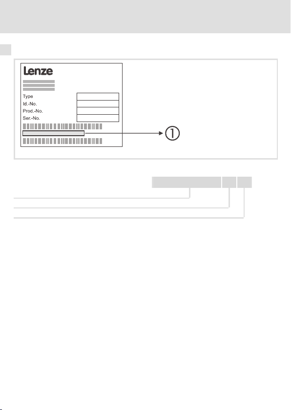
Identifikation
2181FEW099
Typenschlüssel
Gerätereihe
Hardwarestand
Softwarestand
Tipp!
Weiterführende Informationen zu dieser Kommunikationsbaugruppe finden
Sie im entsprechenden Kommunikationshandbuch.
Die PDF-Datei finden Sie im Internet im Bereich ”Services & Downloads” unter
http://www.Lenze.com
12
33.2181IB 1x 1x
EDKMF2181 DE/EN/FR/ES/IT 3.0
Page 13
Allgemeine Daten und Einsatzbedingungen
4 Technische Daten
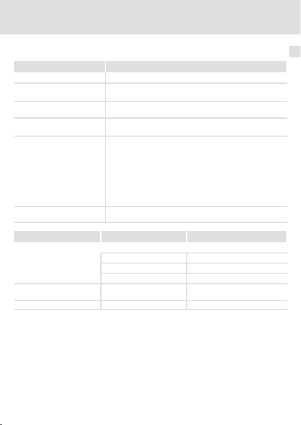
Allgemeine Daten und Einsatzbedingungen
Bereich Werte
Bestell-Bezeichnung EMF2181IB
Kommunikationsmedien
(Anlage)
Kommunikationsmedien
(außerhalb)
Anzahl Teilnehmer am CAN-Bus Max. 100
CAN (DIN ISO 11898)
Lenze-Diagnoseschnittstelle
Telefon analog, 33.6 kBit/s, (V34)
Technische Daten
4
Übertragungsrate
Spannungsversorgung (extern)
über separates Netzteil
Einsatzbedingungen Werte Abweichungen von der Norm
Klimatische Bedingungen
Lagerung 1 K3 nach IEC/EN 60721-3-1 - 10 ... + 60 °C
Transport 2 K3 nach IEC/EN 60721-3-2 - 10 ... + 70 °C
Schutzart des gesteckten Moduls
Verschmutzungsgrad 2 nach IEC/EN 61800-5-1
EDKMF2181 DE/EN/FR/ES/IT 3.0
bei Kommunikation über CAN
– 20 kBit/s
– 50 kBit/s
– 125 kBit/s
– 250 kBit/s
– 500 kBit/s
– 1000 kBit/s
bei Kommunikation über Diagnoseschnittstelle
– 230.4 kBit/s
18 … 30 V DC, max. 100 mA (nach EN 61131-2)
Betrieb 3 K3 nach IEC/EN 60721-3-3 0 ... + 60 °C
IP20
13
Page 14
4 Technische Daten
Schutzisolierung
Schutzisolierung
Anschluss Art der Isolierung (nach EN 61800-5-1)
Telefon Betriebsisolierung
Diagnoseschnittstelle Betriebsisolierung
CAN-Bus Betriebsisolierung
Spannungsversorgung Keine Isolierung
Externes Modem Keine Isolierung
2181FEW001F
14
EDKMF2181 DE/EN/FR/ES/IT 3.0
Page 15
Abmessungen
Technische Daten
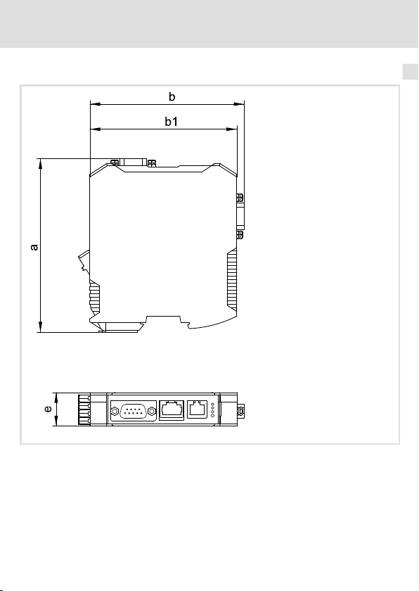
Abmessungen
4
a 117 mm
b 103 mm
b1 99 mm
e 22.5 mm
EDKMF2181 DE/EN/FR/ES/IT 3.0
2181FEW001B
15
Page 16
5 Mechanische Installation
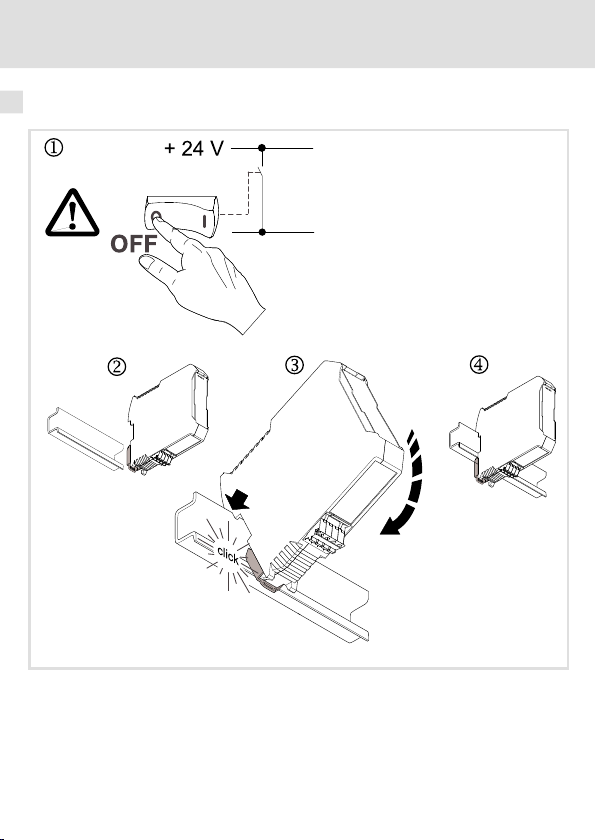
5 MechanischeI nstallation
Montage
16
2181FEW002B
EDKMF2181 DE/EN/FR/ES/IT 3.0
Page 17
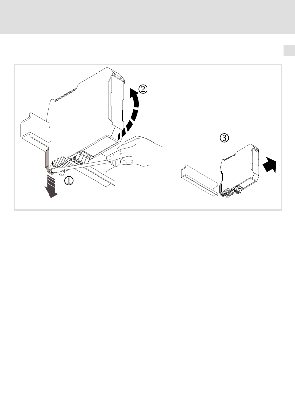
Demontage
Mechanische Installation 5
2181FEW001E
EDKMF2181 DE/EN/FR/ES/IT 3.0
17
Page 18
6 Elektrische Installation
Kommunikation über CAN
6 ElektrischeInstal lation
Kommunikation über CAN
Installationsschritte
Schritt Beschreibung Anschluss
1. Den Sub-D-Stecker (EWZ0046) in das ModemCAN 2181
2. Ist die Verwendung des internen Modems nicht möglich,
3. Den Antriebsregler an den CAN-Bus anschließen.
4. Das ModemCAN 2181 mit dem Telefonnetz verbinden.
5. Die Spannungsversorgung an die Steckerleiste anschlie-
stecken.
schließen Sie ein externes Modem an.
ßen.
(siehe Grafik)
2181FEW008
Zusätzliche
Information
23
29
-
27
30
18
EDKMF2181 DE/EN/FR/ES/IT 3.0
Page 19
Kommunikation über die Diagnoseschnittstelle (Servo Drives 9400)
Elektrische Installation
Kommunikation über die Diagnoseschnittstelle (Servo Drives 9400)
2181FEW007
Die Kommunikation über die Diagnoseschnittstelle empfehlen wir, wenn die Kommunikationsbaugruppe 2181 nur temporär angeschlossen wird.
Bei einer festen Installation ist die Kommunikation über CAN vorzuziehen, siehe (18).
6
EDKMF2181 DE/EN/FR/ES/IT 3.0
19
Page 20
6 Elektrische Installation
Kommunikation über die Diagnoseschnittstelle (Servo Drives 9400)
Installationsschritte
Schritt Beschreibung Anschluss
1. Die Diagnoseschnittstelle mit den Servo Drives 9400
2. Ist die Verwendung des internen Modems nicht möglich,
3. Den Antriebsregler an den CAN-Bus anschließen.
4. Das ModemCAN 2181 mit dem Telefonnetz verbinden.
5. Die Spannungsversorgung an die Steckerleiste anschlie-
verbinden (vorkonfektioniertes Kabel verwenden).
schließen Sie ein externes Modem an.
ßen.
(siehe Grafik)
Zusätzliche
Information
26
29
-
27
30
20
EDKMF2181 DE/EN/FR/ES/IT 3.0
Page 21
Umgang mit Steckerleisten
Stop!
Um Steckerleisten und Kontakte nicht zu beschädigen:
ƒ
Steckerleisten nur aufstecken / abziehen wenn der Antriebsregler vom
Netz getrennt ist.
ƒ
Steckerleisten erst verdrahten, dann aufstecken.
ƒ
Nicht belegte Steckerleisten ebenfalls aufstecken.
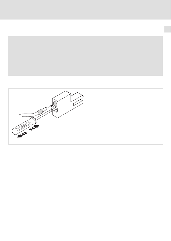
Gebrauch der Steckerleiste mit Federkraftanschluss
Elektrische Installation
Umgang mit Steckerleisten
E82ZAFX013
6
EDKMF2181 DE/EN/FR/ES/IT 3.0
21
Page 22

6 Elektrische Installation
EMV-gerechte Verdrahtung
EMV-gerechte Verdrahtung
Für eine EMV-gerechte Verdrahtung beachten Sie folgende Punkte:
Hinweis!
ƒ
Steuer-/Datenleitungen getrennt von Motorleitungen verlegen.
ƒ
Legen Sie die Schirme der Steuer-/Datenleitungen bei digitalen Signalen
beidseitig
ƒ
ƒ
Vorgehensweise bei der Verdrahtung
1. Bustopologie einhalten, deshalb keine Stichleitungen verwenden.
2. Hinweise und Verdrahtungsvorschriften in den Unterlagen zum Steuerungssystem
beachten.
3. Nur Kabel verwenden, die den aufgeführten Spezifikationen entsprechen (24).
4. Zulässige Busleitungslänge einhalten (25)
5. Hinweise zur Spannungsversorgung der Kommunikationsbaugruppe beachten
(30).
6. Busabschluss-Widerstände von 120Ωam physikalisch ersten und letzten
Busteilnehmer aktivieren.
auf.
Zur Vermeidung von Potenzialdifferenzen zwischen den
Kommunikationsteilnehmern eine Ausgleichsleitung mit einem
Querschnitt von mindestens 16 mm2einsetzen (Bezug: PE).
Beachten Sie die weiteren Hinweise zur EMV-gerechten Verdrahtung in der
Dokumentation des Grundgerätes.
.
22
EDKMF2181 DE/EN/FR/ES/IT 3.0
Page 23
Systembus (CAN) anschließen
1
6
5
9
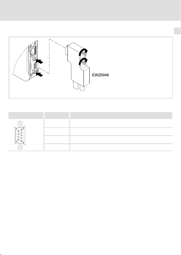
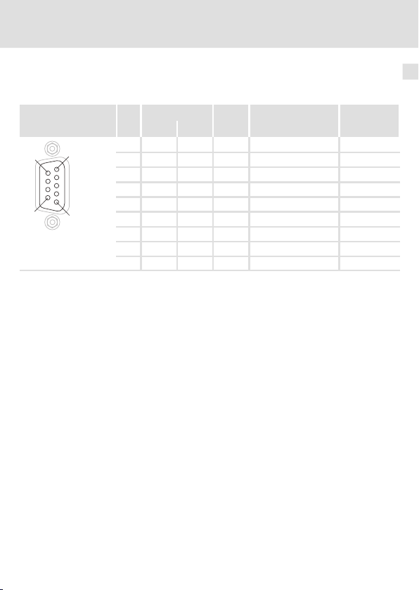
Belegung der Sub-D-Steckerleiste
Ansicht Pin Belegung
1, 4, 5, 6, 8, 9 -
2 CAN-LO
3 CAN-GND
7 CAN-HI
Elektrische Installation
Systembus (CAN) anschließen
2181FEW001K
6
EDKMF2181 DE/EN/FR/ES/IT 3.0
23
Page 24
6 Elektrische Installation
L
EWZ0046
OFF
ON
OFF
ON
ON
OFF
ð
ð
ð
ð
OUTIN IN IN
On
Off
On
120 120
120
L
EWZ0046
L
EWZ0046
L
EWZ0046
Systembus (CAN) anschließen
Der CAN-Bus muss durch Widerstände (120Ω) zwischen CAN-LOW und CAN-HIGH abgeschlossen sein. Der Sub-D-Stecker mit integriertem Abschlusswiderstand (Bestell-Nr.
EWZ0046, nicht im Lieferumfang enthalten) entspricht der Empfehlung DS 102-1 von CiA.
2181FEW004
Spezifikation des Übertragungskabels
Wir empfehlen CAN-Kabel nach ISO 11898-2 zu verwenden:
CAN-Kabel nach ISO 11898-2
Kabeltyp Paarverseilt mit Abschirmung
Impedanz
Leitungswiderstand/-querschnitt
Kabellänge≤300 m≤70 mΩ/m / 0.25 … 0.34 mm2(AWG22)
Kabellänge 301 … 1000 m
Signallaufzeit
Beachten Sie die Informationen zur Busleitungslänge(
120Ω(95 ... 140Ω)
≤
40 mΩ/m / 0.5 mm2(AWG20)
≤
5 ns/m
25)
!
24
EDKMF2181 DE/EN/FR/ES/IT 3.0
Page 25
Elektrische Installation
Systembus (CAN) anschließen
Busleitungslänge
Halten Sie die zulässigen Leitungslängen unbedingt ein.
1. Überprüfen Sie die Einhaltung der Gesamt-Leitungslänge in Tab. 1.
Durch die Übertragungsrate ist die Gesamt-Leitungslänge festgelegt.
Übertragungsrate [kBit/s] Max. Buslänge [m]
20 3600
50 1400
125 550
250 250
500 110
1000 20
Tab. 1 Gesamt-Leitungslänge
2. Überprüfen Sie die Einhaltung der Segment-Leitungslänge in Tab. 2.
Die Segment-Leitungslänge wird durch den verwendeten Leitungsquerschnitt und die Teilnehmeranzahl festgelegt. Ohne Repeater ist die Segment-Leitungslänge gleich der Gesamt-Leitungslänge.
Leitungsquerschnitt
2
Teilnehmer
2 240 m 430 m 650 m 940 m
5 230 m 420 m 640 m 920 m
10 230 m 410 m 620 m 900 m
20 210 m 390 m 580 m 850 m
32 200 m 360 m 550 m 800 m
63 170 m 310 m 470 m 690 m
100 150 m 270 m 410 m 600 m
Tab. 2 Segment-Leitungslänge
0.25 mm
3. VergleichenSie die beiden ermittelten Werte miteinander.
Wenn der aus Tab. 2 ermittelte Wert kleiner als die zu realiserende Gesamt-Leitungslänge
aus Tab. 1 sein sollte, müssen Repeater eingesetzt werden. Repeater unterteilen die Gesamt-Leitungslänge in Segmente.
0.5 mm
2
0.75 mm
2
1.0 mm
2
6
EDKMF2181 DE/EN/FR/ES/IT 3.0
25
Page 26

6 Elektrische Installation
Diagnoseschnittstelle
Diagnoseschnittstelle
Hinweis!
ƒ
Verwenden Sie nur vorkonfektionierte Kabel.
ƒ
Maximale Kabellänge: 10 m bei Verwendungder von Lenze
vorkonfektionierten Leitungen.
Belegung des Diagnosesteckers
Pin Bezeichnung Signal
1 +UB18_DIAG Versorgung (Keypad, PC-Koppler)
2 RTS+
3 RTS-
4 Tx+
5 Tx-
6 Rx+
7 Rx-
8 CTS+
9 CTS-
10 GND Versorgung (Keypad, PC-Koppler)
Gehäuse Abschirmung Abschirmung (mit Blechgehäuse verbunden)
Handshake Grundgerät - Diagnosegerät
Daten Grundgerät - Diagnosegerät
Daten Diagnosegerät - Grundgerät
Handshake Diagnosegerät - Grundgerät
26
EDKMF2181 DE/EN/FR/ES/IT 3.0
Page 27
Elektrische Installation
Telefonverbindung
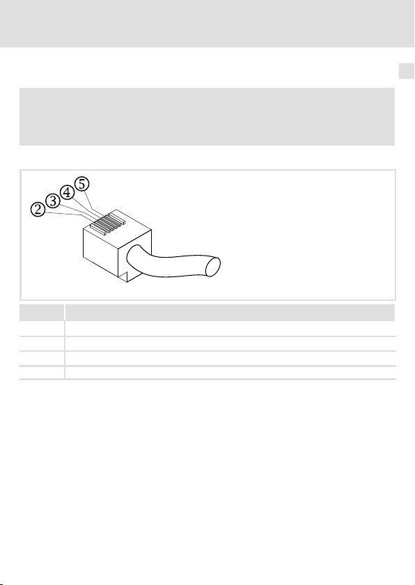
Telefonverbindung
Hinweis!
Verwenden Sie eines der im Lieferumgang der Kommunikationsbaugruppe
enthaltenen vorkonfektionierten Telefonkabel.
Belegung der Telefonbuchse
Pin Bezeichnung
2 nicht belegt
3 La(TIP)
4 Lb(RING)
5 nicht belegt
6
2181FEW003C
EDKMF2181 DE/EN/FR/ES/IT 3.0
27
Page 28
6 Elektrische Installation
1a 1
2b 2
3w 3
4e 4
5a2 5
6b2 6
1 1
2 2
3 3
4 4
5 5
6 6
Telefonverbindung
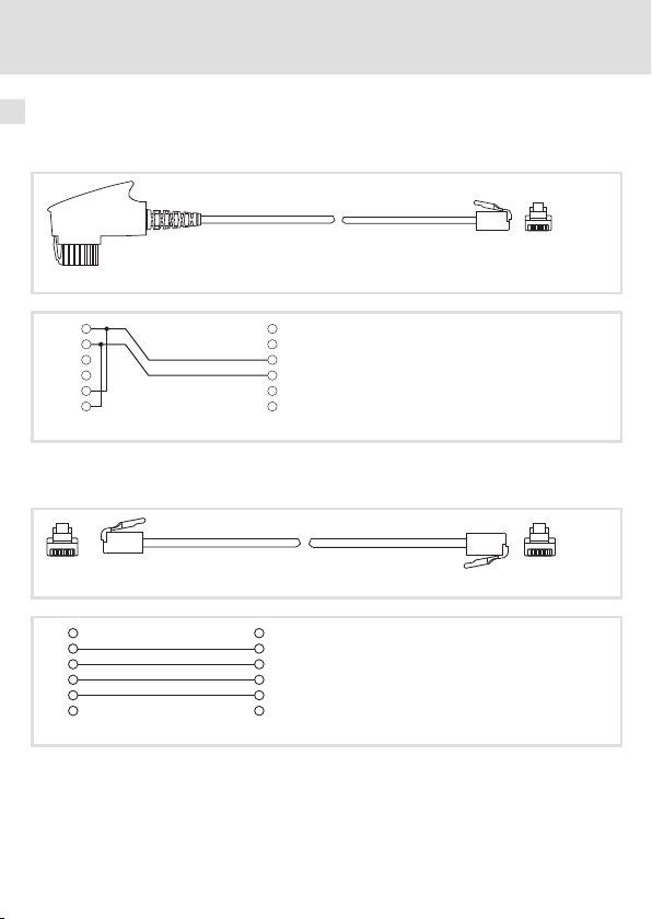
Die Anschlusssteckdosen für Telefone sind weltweit sehr unterschiedlich. Für die wichtigsten Standards sind die folgenden Kabel dem Produkt beigepackt:
TAE-Anschlusskabel
2181FEW012
2181FEW013
Abb. 1 Anschlussbelegung TAE-N-Stecker und RJ11-Stecker (6p/4c)
Modular-Anschlusskabel
2181FEW014
Abb. 2 Anschlussbelegung der beiden RJ11-Stecker (6p/4c)
28
2181FEW015
EDKMF2181 DE/EN/FR/ES/IT 3.0
Page 29
Anschluss für externes Modem
1
6
5
9
Belegung der RS232-Schnittstelle
Ansicht Bezeichnung
Pin V.24 RS232 Signal Signalname Richtung
1 109 CF DCD Data Carrier Detector Ausgang
2 104 BB RD
3 103 BA TD
4 108/2 CD DTR
5 102 AB SG
6 107 CC DSR
7 105 CA RTS
8 106 CB CTS
9 125 CE -
Elektrische Installation
Anschluss für externes Modem
Received Data
Transmitted Data
Data Terminal Ready
Signal Ground
Data Set Ready
Request To Send
Clear To Send
Ring Indicator
Ausgang
Eingang
Eingang
-
Ausgang
Eingang
Ausgang
Ausgang
6
EDKMF2181 DE/EN/FR/ES/IT 3.0
29
Page 30
6 Elektrische Installation
Spannungsversorgung
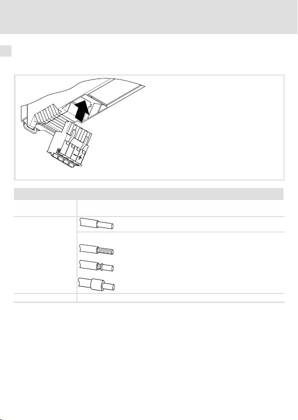
Spannungsversorgung
Daten der Anschlussklemmen
Daten der Anschlussklemmen
Elektrischer An-
schluss
Anschlussmöglichkei-
ten
Abisolierlänge 10 mm
Steckerleiste mit Federkraftanschluss
starr: 2.5 mm2(AWG 12)
flexibel:
ohne Aderendhülse
2.5 mm2(AWG 12)
mit Aderendhülse, ohne Kunststoffhülse
2.5 mm2(AWG 12)
mit Aderendhülse, mit Kunststoffhülse
2.5 mm2(AWG 12)
2181FEW001G
30
EDKMF2181 DE/EN/FR/ES/IT 3.0
Page 31

Vor dem ersten Einschalten
7 Inbetriebnahme
Vor dem ersten Einschalten
Stop!
Überprüfen Sie vor dem Einschalten der Netzspannung die gesamte
Verdrahtung auf Vollständigkeit, Kurzschluss und Erdschluss.
Weiterführende Informationen zur Inbetriebnahme dieser
Kommunikationsbaugruppe finden Sie im Kommunikationshandbuch
Fernwartung.
Inbetriebnahme
7
EDKMF2181 DE/EN/FR/ES/IT 3.0
31
Page 32

8 Diagnose
LED-Statusanzeigen
8 Diagnose
LED-Statusanzeigen
Pos. Farbe Zustand Beschreibung
gelb
(M)
rot
(E)
grün
(R)
grün an Das ModemCAN 2181 wird mit Spannung versorgt.
(P)
an Das ModemCAN 2181 ist betriebsbereit.
blinkt AktiveKommunikation über das Telefonnetz
an
siehe 33
an
siehe 33
Betrieb über Diagnoseschnittstelle:
An der Diagnoseschnittstelle ist kein Gerät angeschlossen.
Betrieb über CAN:
ERR-LED
Betrieb über Diagnoseschnittstelle:
An der Diagnoseschnittstelle ist ein Gerät angeschlossen.
Betrieb über CAN:
RUN-LED
2181FEW0 01H
32
EDKMF2181 DE/EN/FR/ES/IT 3.0
Page 33

LED
Pos. Farbe / Zustand
/
aus
grün
rot
rot
Beschreibung
Verbindung zum Master nicht aufgebaut.
CANopen Zustand (”Z”)
CANopen Fehler (”F”)
Z
: Bus Off
Diagnose
LED-Statusanzeigen
8
blinkt schnell (flackern)
blinkt (grün) im0 .2 s-Takt
blinkt (grün) im0 .2 s-Takt
blinkt (rot) 1 x, 1 s aus
blinkt (grün) im0 .2 s-Takt
blinkt (rot) 2 x, 1 s aus
an (grün)
an (grün)
blinkt (rot) 1 x, 1 s aus
an (grün)
blinkt rot 2 x ,1 s aus
an (grün)
3 x blinkt rot, 1 s aus
blinkt (grün) im1 s-Takt
blinkt (grün) im1 s-Takt
blinkt (rot) 1 x, 1 s aus
blinkt (grün) im1 s-Takt
blinkt rot 2 x, 1 s aus
EDKMF2181 DE/EN/FR/ES/IT 3.0
Automatische Übertragungsratenerkennung ist aktiv.
Z
: Pre-Operational,F: keine
Z
: Pre-Operational,F: Warning Limit reached
Z
: Pre-Operational,F: Node Guard Event
Z
: Operational,F: keine
Z
: Operational,F: Warning Limit reached
Z
: Operational,F: Node Guard Event
Z
: Operational,F: Sync Message Error
Z
: Stopped,F: keine
Z
: Stopped,F: Warning Limit reached
Z
: Stopped,F: Node Guard Event
33
Page 34

Legend for fold-out page
Pos. Description Detailed
information
LED status displays for diagnostics 62
Telephone connection
RJ11 socket
Diagnostics connection
RJ69 socket
CAN connection
RS232 socket (male)
Connection for voltage supply
4-pin plug connector with spring connection
External modem connection
RS232 socket (male)
PE connection
The plugged communication module is automatically connected to the
DIN rail.
The DIN rail must be connected to PE!
1 TAE connecting cable (TAE-N - RJ11) 58
1 Modular connecting cable (RJ11 - RJ11) 58
Mounting instructions
0Fig.0Tab. 0
57
56
53
60
59
34
EDKMF2181 DE/EN/FR/ES/IT 3.0
Page 35

Contents i
1 About this documentation 36. . . . . . . . . . . . . . . . . . . . . . . . . . . . . . . . . . . . . . . . . . .
Conventions used 37. . . . . . . . . . . . . . . . . . . . . . . . . . . . . . . . . . . . . . . . . . . . . . . . . .
Notes used 38. . . . . . . . . . . . . . . . . . . . . . . . . . . . . . . . . . . . . . . . . . . . . . . . . . . . . . . .
2 Safety instructions 40. . . . . . . . . . . . . . . . . . . . . . . . . . . . . . . . . . . . . . . . . . . . . . . . .
3 Product description 41. . . . . . . . . . . . . . . . . . . . . . . . . . . . . . . . . . . . . . . . . . . . . . . . .
Function 41. . . . . . . . . . . . . . . . . . . . . . . . . . . . . . . . . . . . . . . . . . . . . . . . . . . . . . . . .
Application as directed 41. . . . . . . . . . . . . . . . . . . . . . . . . . . . . . . . . . . . . . . . . . . . . .
Scope of supply 41. . . . . . . . . . . . . . . . . . . . . . . . . . . . . . . . . . . . . . . . . . . . . . . . . . . .
Identification 42. . . . . . . . . . . . . . . . . . . . . . . . . . . . . . . . . . . . . . . . . . . . . . . . . . . . . .
4 Technical data 43. . . . . . . . . . . . . . . . . . . . . . . . . . . . . . . . . . . . . . . . . . . . . . . . . . . . .
General data and operating conditions 43. . . . . . . . . . . . . . . . . . . . . . . . . . . . . . .
Protective insulation 44. . . . . . . . . . . . . . . . . . . . . . . . . . . . . . . . . . . . . . . . . . . . . . . .
Dimensions 45. . . . . . . . . . . . . . . . . . . . . . . . . . . . . . . . . . . . . . . . . . . . . . . . . . . . . . .
5 Mechanical installation 46. . . . . . . . . . . . . . . . . . . . . . . . . . . . . . . . . . . . . . . . . . . . .
6 Electrical installation 48. . . . . . . . . . . . . . . . . . . . . . . . . . . . . . . . . . . . . . . . . . . . . . .
Communication via CAN 48. . . . . . . . . . . . . . . . . . . . . . . . . . . . . . . . . . . . . . . . . . . .
Communication via the diagnostic interface (Servo Drives 9400) 49. . . . . . . . . . .
Use of plug connectors 51. . . . . . . . . . . . . . . . . . . . . . . . . . . . . . . . . . . . . . . . . . . . . .
Wiring according to EMC 52. . . . . . . . . . . . . . . . . . . . . . . . . . . . . . . . . . . . . . . . . . . .
Connection of system bus (CAN) 53. . . . . . . . . . . . . . . . . . . . . . . . . . . . . . . . . . . . . .
Diagnostic interface 56. . . . . . . . . . . . . . . . . . . . . . . . . . . . . . . . . . . . . . . . . . . . . . .
Telephone connection 57. . . . . . . . . . . . . . . . . . . . . . . . . . . . . . . . . . . . . . . . . . . . .
External modem connection 59. . . . . . . . . . . . . . . . . . . . . . . . . . . . . . . . . . . . . . . .
Voltage supply 60. . . . . . . . . . . . . . . . . . . . . . . . . . . . . . . . . . . . . . . . . . . . . . . . . . . .
7 Commissioning 61. . . . . . . . . . . . . . . . . . . . . . . . . . . . . . . . . . . . . . . . . . . . . . . . . . . .
Before switching on 61. . . . . . . . . . . . . . . . . . . . . . . . . . . . . . . . . . . . . . . . . . . . . . . .
8 Diagnostics 62. . . . . . . . . . . . . . . . . . . . . . . . . . . . . . . . . . . . . . . . . . . . . . . . . . . . . . .
LED status displays 62. . . . . . . . . . . . . . . . . . . . . . . . . . . . . . . . . . . . . . . . . . . . . . . .
EDKMF2181 DE/EN/FR/ES/IT 3.0
35
Page 36

1 About this documentation
1 Aboutthis documentation
Contents
This documentation provides ...
ƒ Safety instructions that must be observed;
ƒ Information about the mechanical and electrical installation of the communication
module;
ƒ Information about commissioning and diagnostics;
Validity information
The information given in this documentation is valid for the following devices:
Communication module Type designation from hardware
ModemCAN EMF2181IB 1x 1x
Target group
This documentation addresses to persons who project, install, commission, and maintain
the networking and remote maintenance of a machine.
Tip!
Documentation and software updates for further Lenze products can be found
on the Internet in the ”Services & Downloads” area under
http://www.Lenze.com
version
from software
version
36
EDKMF2181 DE/EN/FR/ES/IT 3.0
Page 37

About this documentation
Conventions used
Conventions used
This documentation uses the following conventions to distinguish between differenttypes
of information:
Type of information Identification Examples/notes
Numbers
Decimal separator Point The decimal point is used throughout
Symbols
Page reference
this documentation.
Example: 1234.56
Reference to another page with
additional information
Example:16 = see page 16
1
EDKMF2181 DE/EN/FR/ES/IT 3.0
37
Page 38

1 About this documentation
Notes used
Notes used
The following pictographs and signal words are used in this documentation to indicate
dangers and important information:
Safety instructions
Structure of safety instructions:
Danger!
(characterises the type and severity of danger)
Note
(describes the danger and gives information about how to prevent dangerous
situations)
Pictograph and signal word Meaning
Danger of personal injury through dangerous electrical
voltage.
Danger!
Danger!
Stop!
Reference to an imminent danger that may result in
death or serious personal injury if the corresponding
measures are not taken.
Danger of personal injury through a general source of
danger.
Reference to an imminent danger that may result in
death or serious personal injury if the corresponding
measures are not taken.
Danger of property damage.
Reference to a possible danger that may result in
property damage if the corresponding measures are not
taken.
38
EDKMF2181 DE/EN/FR/ES/IT 3.0
Page 39

Application notes
Pictograph and signal word Meaning
About this documentation
Notes used
1
Note!
Tip!
Important note to ensure troublefree operation
Useful tip for simple handling
Reference to another documentation
EDKMF2181 DE/EN/FR/ES/IT 3.0
39
Page 40

2 Safety instructions
2 Safetyin structions
Danger!
Inappropriate handling of the communication module and the basic device can
cause serious injuries to persons and damage to material assets.
Observe the safety instructions and residual hazards described in the
documentation for the standard device.
Stop!
Electrostatic discharge
Electronic components of the communication module can be damaged or
destroyed through electrostatic discharge.
Possible consequences:
ƒ
The communication module is defective.
ƒ
Fieldbus communication is not possible or faulty.
Protective measures
ƒ
Free yourself from any electrostatic charge before you touch the module.
40
EDKMF2181 DE/EN/FR/ES/IT 3.0
Page 41

Product description
Function
3 Productdescription
Function
The communication module is used for setting parameters during remote maintenance or
programming and commissioning the usable devices:
Application as directed
The communication module can be used with the following Lenze devices:
ƒ Servo Drives 9400
ƒ Inverter Drives 8400
ƒ 9300 servo inverter
ƒ 9300 vector
ƒ 9300 Servo PLC
ƒ ECS servo system
ƒ 8200 motec motor inverter
ƒ 8200 vector frequency inverter
ƒ 82XX frequency inverter
ƒ Drive PLC
ƒ Terminal extension 9374
ƒ Control / display unit (EPM-HXXX)
ƒ I/O system IP20 (EPM-TXXX)
The internal modem supports a series of international specifications and standards.
If the internalmodemcannotbeused,it is possibleto connectan external modem using the
RS232 interface.
Scope of supply
ƒ Communication module EMF2181IB (ModemCAN)
ƒ 1 TAE connecting cable (TAE-N - RJ11)
ƒ 1 Modular connecting cable (RJ11 - RJ11)
ƒ Mounting instructions
3
EDKMF2181 DE/EN/FR/ES/IT 3.0
41
Page 42

3 Product description
Identification
Identification
2181FEW099
Type code
Device series
Hardware version
Software version
Tip!
Further information about this communication module can be found in the
corresponding communication manual.
The pdf file can be found on the Internet in the ”Services & Downloads” area
under
http://www.Lenze.com
42
33.2181IB 1x 1x
EDKMF2181 DE/EN/FR/ES/IT 3.0
Page 43

General data and operating conditions
Technical data
4 Technical data
General data and operating conditions
Range Values
Order designation EMF2181IB
Communication media (system) CAN (DIN ISO 11898)
Communication media
(external)
Number of nodes at the CAN
bus
Baud rate
Voltage supply (external) via
separate power supply
Operating conditions Values Deviations from the standard
Climatic conditions
Storage 1 K3 to IEC/EN 60721-3-1 - 10 ... + 60 °C
Transport 2 K3 acc. to IEC/EN 60721-3-2 - 10 ... + 70 °C
Operation 3 K3 acc. to IEC/EN 60721-3-3 0 ... + 60 °C
Enclosure of attached module IP20
Degree of pollution 2 acc. to IEC/EN 61800-5-1
Lenze diagnostic interface
Telephone analogue, 33.6 kbit/s, (V34)
Max. 100
when communicating via CAN
– 20 kbit/s
– 50 kbit/s
– 125 kbit/s
– 250 kbit/s
– 500 kbit/s
– 1000 kbit/s
For communication via diagnostic interface
– 230.4 kbit/s
18 … 30 V DC, max. 100 mA (in accordance with EN 61131-2)
4
EDKMF2181 DE/EN/FR/ES/IT 3.0
43
Page 44

4 Technical data
Protective insulation
Protective insulation
Connection Type of insulation (according to EN 61800-5-1)
Telephone Functional insulation
Diagnostic interface Functional insulation
CAN bus Functional insulation
Voltage supply No insulation
External modem No insulation
2181FEW001F
44
EDKMF2181 DE/EN/FR/ES/IT 3.0
Page 45

Dimensions
Technical data
Dimensions
4
A 117 mm
B 103 mm
b1 99 mm
E 22.5 mm
EDKMF2181 DE/EN/FR/ES/IT 3.0
2181FEW001B
45
Page 46

5 Mechanical installation
5 Mechanical installation
Mounting
46
2181FEW002B
EDKMF2181 DE/EN/FR/ES/IT 3.0
Page 47

Dismounting
Mechanical installation 5
2181FEW001E
EDKMF2181 DE/EN/FR/ES/IT 3.0
47
Page 48

6 Electrical installation
Communication via CAN
6 Electricalinstall ation
Communication via CAN
Installation steps
Step Description Connection
1. Plug the Sub-D plug (EWZ0046) into the ModemCAN
2. If it is not possible to use the internal modem, connect
3. Connect the controller to the CAN bus.
4. Connect the ModemCAN 2181 to the telephone network.
5. Connect the voltage supply to the plug connector.
2181.
an external modem.
(see graphic)
2181FEW008
Additional
information
53
59
-
57
60
48
EDKMF2181 DE/EN/FR/ES/IT 3.0
Page 49

Communication via the diagnostic interface (Servo Drives 9400)
Electrical installation
Communication via the diagnostic interface (Servo Drives 9400)
2181FEW007
Communicating via the diagnostic interface is recommended if the 2181 communication
module is only connected temporarily.
In case of a fixed installation the communication via CAN should be preferred, see (48).
6
EDKMF2181 DE/EN/FR/ES/IT 3.0
49
Page 50

6 Electrical installation
Communication via the diagnostic interface (Servo Drives 9400)
Installation steps
Step Description Connection
1. Connect the diagnostic interface to the Servo Drives
2. If it is not possible to use the internal modem, connect
3. Connect the controller to the CAN bus.
4. Connect the ModemCAN 2181 to the telephone network.
5. Connect the voltage supply to the plug connector.
9400 (use prefabricated cable)
an external modem.
(see graphic)
Additional
information
56
59
-
57
60
50
EDKMF2181 DE/EN/FR/ES/IT 3.0
Page 51

Electrical installation
Use of plug connectors
Stop!
Observe the following to prevent any damage to plug connectors and
contacts:
ƒ
Only pug in / unplug the plug connectors when the controller is
disconnected from the mains.
ƒ
Wire the plug connectors before plugging them in.
ƒ
Unused plug connectors must also be plugged in.
Use of plug connectors with spring connection
Use of plug connectors
6
E82ZAFX013
EDKMF2181 DE/EN/FR/ES/IT 3.0
51
Page 52

6 Electrical installation
Wiring according to EMC
Wiring according to EMC
For wiring according to EMC requirements observe the following points:
Note!
ƒ
Separate control cables/data lines from motor cables.
ƒ
Connect the shields of control cables/data lines
digital signals.
ƒ
Use an equalizing conductor with a cross-section of at least 16 mm
(reference: PE) to avoid potential differences between the bus nodes.
ƒ
Observe the other notes concerning EMC-compliant wiring given in the
documentation for the standard device.
Wiring procedure
1. Observe the bus topology, do not use any stubs.
2. Follow the wiring notes given in the documentation for the control system.
3. Only use cables that correspond to the listed specifications (54).
4. Observe the permissible bus cable length (55)
5. Observe the voltage supply notes for the communication module(60).
6. Activate bus terminating resistors of 120Ωat the physically first and last node.
.
at both ends
in the case of
2
52
EDKMF2181 DE/EN/FR/ES/IT 3.0
Page 53

Connection of system bus (CAN)
1
6
5
9
Assignment of the Sub-D plug connector
View Pin Assignment
1, 4, 5, 6, 8, 9 -
2 CAN-LO
3 CAN-GND
7 CAN-HI
Electrical installation
Connection of system bus (CAN)
2181FEW001K
6
EDKMF2181 DE/EN/FR/ES/IT 3.0
53
Page 54

6 Electrical installation
L
EWZ0046
OFF
ON
OFF
ON
ON
OFF
ð
ð
ð
ð
OUTIN IN IN
On
Off
On
120 120
120
L
EWZ0046
L
EWZ0046
L
EWZ0046
Connection of system bus (CAN)
Between CAN_LOW and CAN-HIGH the CAN bus has to be terminated by resistors (120Ω).
The Sub-D plug with an integrated terminating resistor (order no. EWZ0046, not included
in the scope of supply) complies with the recommendation DS 102-1 of CiA.
2181FEW004
Specification of the transmissioncable
We recommend the use of CAN cables in accordance with ISO 11898-2:
CAN cable in accordance withISO 11898-2
Cable type Paired with shielding
Impedance
Cable resistance/cross-section
Cable length≤300 m≤70 mΩ/m / 0.25 … 0.34 mm2(AWG22)
Cable length 301 … 1000 m
Signal propagation delay
Observe the information on the bus cable length
120Ω(95 ... 140Ω)
≤
40 mΩ/m / 0.5 mm2(AWG20)
≤
5 ns/m
(55)
!
54
EDKMF2181 DE/EN/FR/ES/IT 3.0
Page 55

Electrical installation
Connection of system bus (CAN)
Bus cable length
It is absolutely necessary to comply with the permissible cable lengths.
1. Check the compliance with the total cable length in Tab. 1.
The total cable length is determined by the baud rate.
Baud rate [kbit/s] Max. bus length [m]
20 3600
50 1400
125 550
250 250
500 110
1000 20
Tab. 1 Total cable length
2. Check the compliance with the segment cable length in Tab. 2.
The segment cable length is determined by the cable cross-sectionusedandby the number
of nodes.Withoutrepeatersthe segment cable lengthcorrespondstothetotalcablelength.
Cable cross-section
2
Nodes
2 240 m 430 m 650 m 940 m
5 230 m 420 m 640 m 920 m
10 230 m 410 m 620 m 900 m
20 210 m 390 m 580 m 850 m
32 200 m 360 m 550 m 800 m
63 170 m 310 m 470 m 690 m
100 150 m 270 m 410 m 600 m
Tab. 2 Segment cable length
0.25 mm
3. Compare both values.
If the value given in Tab. 2 is smaller than the required total cable length from Tab. 1,
repeaters must be used. Repeaters divide the total cable length into segments.
0.5 mm
2
0.75 mm
2
1.0 mm
2
6
EDKMF2181 DE/EN/FR/ES/IT 3.0
55
Page 56

6 Electrical installation
Diagnostic interface
Diagnostic interface
Note!
ƒ
Please only use prefabricated cables.
ƒ
Maximum cable length: 10 m when the cables prefabricated by Lenze are
used.
Assignment of the diagnostic connector
Pin Name Signal
1 +UB18_DIAG Supply (keypad, PC coupler)
2 RTS+
3 RTS-
4 Tx+
5 Tx-
6 Rx+
7 Rx-
8 CTS+
9 CTS-
10 GND Supply (keypad, PC coupler)
Housing Shielding Shielding (connected to metal housing)
Handshake, basic device - diagnostic device
Data, basic device - diagnostic device
Data, diagnostic device - basic device
Handshake, diagnostic device - basic device
56
EDKMF2181 DE/EN/FR/ES/IT 3.0
Page 57

Electrical installation
Telephone connection
Telephone connection
Note!
Use one of the prefabricated telephone cables included in the scope of supply
of the communication module.
Assignment of the telephone socket
Pin Designation
2 not assigned
3 La(TIP)
4 Lb(RING)
5 not assigned
6
2181FEW003C
EDKMF2181 DE/EN/FR/ES/IT 3.0
57
Page 58

6 Electrical installation
1a 1
2b 2
3w 3
4e 4
5a2 5
6b2 6
1 1
2 2
3 3
4 4
5 5
6 6
Telephone connection
Worldwide, the telephone sockets differ from each other. For the most important
standards, the following cables are supplied with the product:
TAE connecting cable
2181FEW012
2181FEW013
Fig. 1 Terminal assignment TAE-N plug and RJ11 plug (6p/4c)
Modular connecting cable
2181FEW014
Fig. 2 Terminal assignment of the two RJ11 plugs (6p/4c)
58
2181FEW015
EDKMF2181 DE/EN/FR/ES/IT 3.0
Page 59

External modem connection
1
6
5
9
Assignment of the RS232 interface
View Designation
Pin V.24 RS232 Signal Signalname Direction
1 109 CF DCD Data Carrier Detector Output
2 104 bb RD
3 103 BA TD
4 108/2 CD DTR
5 102 from SG
6 107 cc DSR
7 105 CA RTS
8 106 CB CTS
9 125 CE -
Electrical installation
External modem connection
Data
Transmitted Data
Data Terminal Ready
Signal Ground
Data Set Ready
Request To Send
Clear To Send
Ring Indicator
Output
Input
Input
-
Output
Input
Output
Output
6
EDKMF2181 DE/EN/FR/ES/IT 3.0
59
Page 60

6 Electrical installation
Voltage supply
Voltage supply
Terminal data
Terminal data
Electrical connection Plug connector with spring connection
Possible connections
Stripping length 10 mm
rigid: 2.5 mm2(AWG 12)
flexible:
without wire end ferrule
2.5 mm2(AWG 12)
with wire end ferrule, without plastic sleeve
2.5 mm2(AWG 12)
with wire end ferrule, with plastic sleeve
2.5 mm2(AWG 12)
2181FEW001G
60
EDKMF2181 DE/EN/FR/ES/IT 3.0
Page 61

Commissioning
Before switching on
7 Commissioning
Before switching on
Stop!
Prior to switching on the mains voltage, check the wiring for completeness,
short-circuit and earth fault.
Further information on how to commission this communication module can
be found in the maintenance communication manual.
7
EDKMF2181 DE/EN/FR/ES/IT 3.0
61
Page 62

8 Diagnostics
LED status displays
8 Diagnostics
LED status displays
Pos. Colour State Description
yellow
(M)
red
(E)
green
(R)
green on The ModemCAN 2181 is supplied with voltage.
(P)
on The ModemCAN 2181 is ready for operation.
blinking Active communication over the telephone network
on
see 63
on
see 63
Operation via the diagnostic interface:
No device is connected to the diagnostic
interface.
Operation via CAN:
ERR LED
Operation via the diagnostic interface:
A device is connectedto the diagnostic
interface.
Operation via CAN:
RUN-LED
2181FEW0 01H
62
EDKMF2181 DE/EN/FR/ES/IT 3.0
Page 63

LED
Pos. Colour / status
+
off
green
red
red
Description
Connection to master not established.
CANopen status (”Z”)
CANopen error (”F”)
Z
: Bus off
Diagnostics
LED status displays
8
blinking fast (jittering)
blinking (green)e very 0.2 s
blinking (green)e very 0.2 s
blinking (red) 1 x, 1 s off
blinking (green)e very 0.2 s
blinking (red) 2 x, 1 s off
on (green)
on (green)
blinking (red) 1 x, 1 s off
on (green)
blinking red 2 x, 1 s off
on (green)
3 x blinking red, 1 s off
blinking (green)once p er
second
blinking (green)once p er
second
blinking (red) 1 x, 1 s off
blinking (green)once p er
second
blinking red 2 x, 1 s off
EDKMF2181 DE/EN/FR/ES/IT 3.0
Automatic baud rate recognition is active.
Z
: Pre-Operational,F: None
Z
: Pre-Operational,F: Warning limit reached
Z
: Pre-Operational,F: Node guard event
Z
: Operational,F: None
Z
: Operational,F: Warning limit reached
Z
: Operational,F: Node guard event
Z
: Operational,F: Sync message error
Z
: Stopped,F: None
Z
: Stopped,F: Warning limit reached
Z
: Stopped,F: Node guard event
63
Page 64

Légende de l’illustration dela page dépliante
Pos. Description Informations
détaillées
Affichages d’état par LED à des fins de diagnostic 92
Raccordement téléphonique
Prise RJ11
Port de diagnostic
Prise RJ69
Port CAN
Prise RS232 (mâle)
Raccordement de l’alimentation
Bornier à lame ressort 4 bornes
Raccordement d’un modem externe
Prise RS232 (mâle)
Raccordement PE
Le module de communication enfiché est automatiquement en contact
avec le rail profilé.
Le rail profilé doit être relié à la terre (PE) !
Câble de raccordement 1 TAE (TAE-N - RJ11) 88
1 câble de raccordement modulaire (RJ11 - RJ11) 88
Instructions de montage
0Fig.0Tab. 0
87
86
83
90
89
64
EDKMF2181 DE/EN/FR/ES/IT 3.0
Page 65

Sommaire i
1 Présentation du document 66. . . . . . . . . . . . . . . . . . . . . . . . . . . . . . . . . . . . . . . . . . .
Conventions utilisées 67. . . . . . . . . . . . . . . . . . . . . . . . . . . . . . . . . . . . . . . . . . . . . . .
Consignes utilisées 68. . . . . . . . . . . . . . . . . . . . . . . . . . . . . . . . . . . . . . . . . . . . . . . . .
2 Consignes de sécurité 70. . . . . . . . . . . . . . . . . . . . . . . . . . . . . . . . . . . . . . . . . . . . . . .
3 Description du produit 71. . . . . . . . . . . . . . . . . . . . . . . . . . . . . . . . . . . . . . . . . . . . . .
Fonction 71. . . . . . . . . . . . . . . . . . . . . . . . . . . . . . . . . . . . . . . . . . . . . . . . . . . . . . . . .
Utilisation conforme à la fonction 71. . . . . . . . . . . . . . . . . . . . . . . . . . . . . . . . . . . . .
Equipement livré 71. . . . . . . . . . . . . . . . . . . . . . . . . . . . . . . . . . . . . . . . . . . . . . . . . . .
Identification 72. . . . . . . . . . . . . . . . . . . . . . . . . . . . . . . . . . . . . . . . . . . . . . . . . . . . . .
4 Spécifications techniques 73. . . . . . . . . . . . . . . . . . . . . . . . . . . . . . . . . . . . . . . . . . .
Caractéristiques générales et conditions d’utilisation 73. . . . . . . . . . . . . . . . . . . .
Isolement de protection 74. . . . . . . . . . . . . . . . . . . . . . . . . . . . . . . . . . . . . . . . . . . . .
Encombrements 75. . . . . . . . . . . . . . . . . . . . . . . . . . . . . . . . . . . . . . . . . . . . . . . . . . .
5 Installation mécanique 76. . . . . . . . . . . . . . . . . . . . . . . . . . . . . . . . . . . . . . . . . . . . . .
6 Installation électrique 78. . . . . . . . . . . . . . . . . . . . . . . . . . . . . . . . . . . . . . . . . . . . . . .
Communication par bus CAN 78. . . . . . . . . . . . . . . . . . . . . . . . . . . . . . . . . . . . . . . .
Communication via interface de diagnostic (Servo Drives 9400) 79. . . . . . . . . . . .
Utilisation de borniers 81. . . . . . . . . . . . . . . . . . . . . . . . . . . . . . . . . . . . . . . . . . . . . .
Câblage conforme CEM 82. . . . . . . . . . . . . . . . . . . . . . . . . . . . . . . . . . . . . . . . . . . . . .
Raccordement du Bus Système CAN 83. . . . . . . . . . . . . . . . . . . . . . . . . . . . . . . . . . .
Interface de diagnostic 86. . . . . . . . . . . . . . . . . . . . . . . . . . . . . . . . . . . . . . . . . . . . .
Liaison téléphonique 87. . . . . . . . . . . . . . . . . . . . . . . . . . . . . . . . . . . . . . . . . . . . . . .
Raccordement d’un modem externe 89. . . . . . . . . . . . . . . . . . . . . . . . . . . . . . . . . . .
Alimentation 90. . . . . . . . . . . . . . . . . . . . . . . . . . . . . . . . . . . . . . . . . . . . . . . . . . . . .
7 Mise en service 91. . . . . . . . . . . . . . . . . . . . . . . . . . . . . . . . . . . . . . . . . . . . . . . . . . . .
Avant la première mise sous tension 91. . . . . . . . . . . . . . . . . . . . . . . . . . . . . . . . . . .
8 Diagnostic 92. . . . . . . . . . . . . . . . . . . . . . . . . . . . . . . . . . . . . . . . . . . . . . . . . . . . . . . .
Affichages d’état par LED 92. . . . . . . . . . . . . . . . . . . . . . . . . . . . . . . . . . . . . . . . . . .
EDKMF2181 DE/EN/FR/ES/IT 3.0
65
Page 66

1 Présentation du document
1 Présentationdu document
Contenu
La présente documentation contient ...
ƒ des consignes de sécurité qui doivent impérativement être respectées ;
ƒ des informations sur l’installation mécanique et électrique du module de
communication ;
ƒ des informations relatives à la mise en service et au diagnostic.
Informations relatives à la validité
Les informations contenues dans leprésentdocuments’appliquentaux appareils suivants :
Module de communication Référence de
ModemCAN EMF2181IB 1x 1x
Public visé
Ce document s’adresse aux personnes chargées de la conception, de l’installation, de la
mise en service et de la maintenance de la connexion au réseau et de la télémaintenance
d’une machine.
Conseil !
Les mises à jour de logiciels et les documentations relatives aux produits Lenze
sont disponibles dans la zone ”Téléchargements” du site Internet :
http://www.Lenze.com
commande
A partir de la version
matérielle
A partir de la version
logicielle
66
EDKMF2181 DE/EN/FR/ES/IT 3.0
Page 67

Présentation du document
Conventions utilisées
Conventions utilisées
Pour faire la distinction entre différents types d’informations, ce document utilise les
conventions suivantes :
Type d’information Marquage Exemples/remarques
Représentation des chiffres
Séparateur décimal Point Le point décimal est généralement
Symboles
Renvoi à une page
utilisé.
Exemple : 1234.56
Renvoi à une autre page présentant
des informations supplémentaires
Exemple :16 = voir page 16
1
EDKMF2181 DE/EN/FR/ES/IT 3.0
67
Page 68

1 Présentation du document
Consignes utilisées
Consignes utilisées
Pour indiquer des risques et des informations importantes, la présente documentation
utilise les mots et symboles suivants :
Consignes de sécurité
Présentation des consignes de sécurité
Danger !
(Le pictogramme indique le type de risque.)
Explication
(L’explication décrit le risque et les moyens de l’éviter.)
Pictogramme et mot associé Explication
Situation dangereuse pour les personnes en raison d’une
tension électrique élevée
Danger !
Danger !
Stop !
Indication d’un danger imminent qui peut avoir pour
conséquences des blessures mortelles ou très graves en
cas de non-respect des consignes de sécurité
correspondantes
Situation dangereuse pour les personnes en raison d’un
danger d’ordre général
Indication d’un danger imminent qui peut avoir pour
conséquences des blessures mortelles ou très graves en
cas de non-respect des consignes de sécurité
correspondantes
Risques de dégâts matériels
Indication d’un risque potentiel qui peut avoir pour
conséquences des dégâts matériels en cas de non-respect
des consignes de sécurité correspondantes
68
EDKMF2181 DE/EN/FR/ES/IT 3.0
Page 69

Consignes d’utilisation
Pictogramme et mot associé Explication
Présentation du document
Consignes utilisées
1
Remarque
importante !
Conseil !
Remarque importante pour assurer un fonctionnement
correct
Conseil utile pour faciliter la mise en oeuvre
Référence à une autre documentation
EDKMF2181 DE/EN/FR/ES/IT 3.0
69
Page 70

2 Consignes de sécurité
2 Consignesde sécurité
Danger !
Toute utilisation non conforme à la fonction du module de communication et
de l’appareil de base risque d’entraîner des dommages corporels et matériels
graves.
Tenir compte des consignes de sécurité et des dangers résiduels énoncés dans
la documentation de l’appareil de base.
Stop !
Décharges électrostatiques
Les décharges électrostatiques risquent d’endommager ou de détruire des
composants électroniques du module de communication.
Risques encourus :
ƒ
Défaillance du module de communication
ƒ
La communication par bus de terrain est impossible ou erronée.
Mesures de protection :
ƒ
Toute personne amenée à manipuler le module doit se libérer au préalable
des décharges électrostatiques.
70
EDKMF2181 DE/EN/FR/ES/IT 3.0
Page 71

Description du produit
Fonction
3 Descriptiondu produit
Fonction
Le module de communication est destiné au paramétrage / à la programmation et à la mise
en service à distance des appareils compatibles.
Utilisation conforme à la fonction
Le module de communication est compatible avec les appareils Lenze ci-dessous :
ƒ Servo Drives 9400
ƒ Inverter Drives 8400
ƒ Servovariateurs 9300
ƒ 9300 vector
ƒ Servovariateurs 9300 PLC
ƒ Système servo ECS
ƒ Motovariateurs 8200 motec
ƒ Convertisseurs de fréquence 8200 vector
ƒ Convertisseurs de fréquence 82XX
ƒ Drive PLC
ƒ Bornes décentralisées 9374
ƒ Interfaces homme-machine (EPM-HXXX)
ƒ Système E/S IP20 (EPM-TXXX)
Le modem interne prend en charge toute une série de spécifications et normes
internationales.
Pour remplacer le modem interne, un modem externe peut être raccordé via l’interface
RS232.
Equipement livré
ƒ Module de communication EMF2181IB (ModemCAN)
ƒ Câble de raccordement 1 TAE (TAE-N - RJ11)
ƒ 1 câble de raccordement modulaire (RJ11 - RJ11)
ƒ Instructions de montage
3
EDKMF2181 DE/EN/FR/ES/IT 3.0
71
Page 72

3 Description du produit
Identification
Identification
2181FEW099
Codification des types
Série d’appareils
Version matérielle
Version logicielle
Conseil !
Pour plus d’informations sur ce module de communication, se reporter au
manuel de communication correspondant.
Le fichier PDF peut être téléchargé sur Internet depuis la section ”Services &
Downloads” de notre site à l’adresse suivante :
http://www.Lenze.com
72
33.2181IB 1x 1x
EDKMF2181 DE/EN/FR/ES/IT 3.0
Page 73

Caractéristiques générales et conditions d’utilisation
Spécifications techniques
4 Spécifications techniques
Caractéristiques générales et conditions d’utilisation
Domaine Valeurs
Réf. de commande EMF2181IB
Support de communication
(installation)
Support de communication
(externe)
Nombre de participants au bus
CAN
Vitesse de transmission
Alimentation (externe) via bloc
d’alimentation séparé
CAN (DIN ISO 11898)
Interface de diagnostic Lenze
Téléphone analogique, 33.6 kbits/s, (V34)
100 max.
Communication via le bus CAN
– 20 kbits/s
– 50 kbits/s
– 125 kbits/s
– 250 kbits/s
– 500 kbits/s
– 1000 kbits/s
Communication via interface de diagnostic
– 230,4 kbits/s
18 … 30 V CC, 100 mA max. (suivant EN 61131-2)
4
Conditions d’utilisation Valeurs Plage de température élargie par
Conditions climatiques
Stockage Classe 1 K3 suivant la norme
CEI/EN 60721-3-1
Transport Classe 2 K3 suivant la norme
Fonctionnement Classe 3 K3 suivant la norme
Indice de protection du
module enfiché
Degré de pollution Degré 2 suivant la norme
EDKMF2181 DE/EN/FR/ES/IT 3.0
CEI/EN 60721-3-2
CEI/EN 60721-3-3
IP20
CEI/EN 61800-5-1
rapport à la norme
- 10 ... + 60 °C
- 10 ... + 70 °C
0 ... + 60 °C
73
Page 74

4 Spécifications techniques
Isolement de protection
Isolement de protection
Raccordement Type d’isolement (selon EN 61800 -5-1)
Téléphone Isolement fonctionnel
Interface de diagnostic Isolement fonctionnel
Bus CAN Isolement fonctionnel
Alimentation Pas d’isolement
Modem externe Pas d’isolement
2181FEW001F
74
EDKMF2181 DE/EN/FR/ES/IT 3.0
Page 75

Encombrements
Spécifications techniques
Encombrements
4
a 117 mm
b 103 mm
b1 99 mm
e 22,5 mm
EDKMF2181 DE/EN/FR/ES/IT 3.0
2181FEW001B
75
Page 76

5 Installation mécanique
5 Installationm écanique
Montage
76
2181FEW002B
EDKMF2181 DE/EN/FR/ES/IT 3.0
Page 77

Démontage
Installation mécanique 5
2181FEW001E
EDKMF2181 DE/EN/FR/ES/IT 3.0
77
Page 78

6 Installation électrique
Communication par bus CAN
6 Installationé lectrique
Communication par bus CAN
Etapes de l’installation
Etape Description Raccordement
1. Enficher le connecteur SUB-D mâle (EWZ0046) dans
2. Si l’utilisation d’un modem intégré s’avère
3. Raccorder le variateur au Bus Système CAN.
4. Relier le ModemCAN 2181 au réseau téléphonique.
5. Raccorder l’alimentation au bornier enfichable.
le ModemCAN 2181.
impossible, raccorder un modem externe.
(voir schéma)
2181FEW008
Informations
complémentaires
83
89
-
87
90
78
EDKMF2181 DE/EN/FR/ES/IT 3.0
Page 79

Communication via interface de diagnostic (Servo Drives 9400)
Installation électrique
Communication via interface de diagnostic (Servo Drives 9400)
2181FEW007
La communication via l’interface de diagnostic est recommandée lorsque le module de
communication 2181 n’est que provisoirement raccordé.
En cas d’installation fixe, privilégier la communication par bus CAN (voir (78).
6
EDKMF2181 DE/EN/FR/ES/IT 3.0
79
Page 80

6 Installation électrique
Communication via interface de diagnostic (Servo Drives 9400)
Etapes de l’installation
Etape Description Raccordement
1. Relier l’interface de diagnostic au Servo Drive 9400
2. Si l’utilisation d’un modem intégré s’avère
3. Raccorder le variateur au Bus Système CAN.
4. Relier le ModemCAN 2181 au réseau téléphonique.
5. Raccorder l’alimentation au bornier enfichable.
(utilisé le câble préconfectionné).
impossible, raccorder un modem externe.
(voir schéma)
Informations
complémentaires
86
89
-
87
90
80
EDKMF2181 DE/EN/FR/ES/IT 3.0
Page 81

Utilisation de borniers
Stop !
Pour éviter d’endommager les borniers et les contacts :
ƒ
Enficher et retirer les borniers uniquement lorsque le variateur est coupé
du réseau.
ƒ
Procéder au câblage des borniers avant de les enficher.
ƒ
Enficher également des borniers non affectés.
Utilisation de borniers à lame ressort
Installation électrique
Utilisation de borniers
E82ZAFX013
6
EDKMF2181 DE/EN/FR/ES/IT 3.0
81
Page 82

6 Installation électrique
Câblage conforme CEM
Câblage conforme CEM
Pour s’assurer que le câblage est conforme aux exigences à respecter en matière de CEM,
vérifier les points suivants :
Remarque importante !
ƒ
Séparer physiquement les câbles de commande/de données des câbles
moteur.
ƒ
Pour les signaux numériques, blinder les câbles de commande et de
données
ƒ
ƒ
Procédure à suivre pour le câblage
1. Se conformer à la topologie du bus. Par conséquent, ne pas utiliser de câbles de
dérivation.
2. Respecter les indications et prescriptions concernant le câblage fournies dans la
documentation du système de commande.
3. Utiliser uniquement des câbles correspondant aux spécifications fournies (84).
4. Respecter la longueur de câble bus max. admissible (85)
5. Respecter les indications concernant l’alimentation du module de communication
(90).
6. Activer des résistances d’extrémité de bus de 120Ωau niveau du premier et du
dernier participant physique au bus.
aux deux extrémités
Pour éviter les différences de potentiel entre les participants au bus, utiliser
une ligne de compensation d’une section minimale de 16 mm2(référence :
PE).
Respecter les autres consignes relatives au câblage conforme CEM fournies
dans la documentation de l’appareil de base.
.
.
82
EDKMF2181 DE/EN/FR/ES/IT 3.0
Page 83

Raccordement du Bus Système CAN
1
6
5
9
Affectation du connecteur Sub-D
Illustration Broche Affectation
1, 4, 5, 6, 8, 9 -
2 CAN-LO
3 CAN-GND
7 CAN-HI
Installation électrique
Raccordement du Bus Système CAN
2181FEW001K
6
EDKMF2181 DE/EN/FR/ES/IT 3.0
83
Page 84

6 Installation électrique
L
EWZ0046
OFF
ON
OFF
ON
ON
OFF
ð
ð
ð
ð
OUTIN IN IN
On
Off
On
120 120
120
L
EWZ0046
L
EWZ0046
L
EWZ0046
Raccordement du Bus Système CAN
Le bus CAN doit être fermé par des résistances (120Ω) entre CAN-LOW et CAN-HIGH. Le
connecteur Sub-D mâle avec résistance d’extrémité intégrée (réf. de commande EWZ0046,
non compris dans l’équipement livré) correspond à la recommandation DS 102-1 du groupe
CiA.
2181FEW004
Spécifications pour câble de transmission
Il est recommandé d’utiliser des câbles CAN conformes à la norme ISO 11898-2 :
Câbles CAN conformes à la norme ISO 11898-2
Type de câble Paire blindée
Impédance
Résistivité et section de câble
Longueur de câble≤300 m≤70 mΩ/m / 0,25 … 0,34 mm2(AWG22)
Longueur de câble 301 … 1000 m
Temps de parcours du signal
Respecter les indications relatives à la longueur du câble bus
120Ω(95 ... 140Ω)
≤
40 mΩ/m / 0,5 mm2(AWG20)
≤
5 ns/m
(85)
!
84
EDKMF2181 DE/EN/FR/ES/IT 3.0
Page 85

Installation électrique
Raccordement du Bus Système CAN
Longueur de bus
Respecter impérativement les longueurs de câble autorisées !
1. Vérifier la longueur de câble totale admise dans le Tab. 1.
La longueur totale de câble est déterminée par la vitesse de transmission.
Vitesse de transmission
[kbits/s]
20 3600
50 1400
125 550
250 250
500 110
1000 20
Tab. 1 Longueur de câble totale
2. Vérifier la longueur de câble admise par segment dans le Tab. 2.
La longueur de câble par segment est déterminée par la section de câble utilisée et par le
nombre de participants. Sans répétiteur, la longueur de câble par segment équivaut à la
longueur de câble totale.
Nombre de
participants
2 240 m 430 m 650 m 940 m
5 230 m 420 m 640 m 920 m
10 230 m 410 m 620 m 900 m
20 210 m 390 m 580 m 850 m
32 200 m 360 m 550 m 800 m
63 170 m 310 m 470 m 690 m
100 150 m 270 m 410 m 600 m
Tab. 2 Longueur de câble par segment
Section de câble
0,25 mm
3. Comparer les valeurs déterminées.
Si la valeur établie à partir du Tab. 2 est inférieure à la longueur de câble totale à réaliser
d’après le Tab. 1, il est nécessaire d’avoir recours à des répétiteurs. Les répétiteurs divisent
la longueur de câble totale en segments.
Longueur de bus max. [m]
2
0,5 mm
2
0,75 mm
2
1,0 mm
2
6
EDKMF2181 DE/EN/FR/ES/IT 3.0
85
Page 86

6 Installation électrique
Interface de diagnostic
Interface de diagnostic
Remarque importante !
ƒ
Utiliser exclusivement des câbles préconfectionnés.
ƒ
Longueur de câble maximale : 10 m avec les câbles préconfectionnés de
Lenze.
Affectation des broches de la prise de diagnostic
Broche Désignation Signal
1 +UB18_DIAG Alimentation (clavier de commande, coupleur PC)
2 RTS+
3 RTS-
4 Tx +
5 Tx -
6 Rx +
7 Rx -
8 CTS+
9 CTS-
10 GND Alimentation (clavier de commande,coupleur PC)
Boîtier Blindage Blindage (raccordé au boîtier en tôle)
Handshake entre l’appareil de base et le système de
diagnostic
Données entre l’appareil de base et le système de diagnostic
Données entre le système de diagnostic et l’appareil de base
Handshake entre le système de diagnostic et l’appareil de
base
86
EDKMF2181 DE/EN/FR/ES/IT 3.0
Page 87

Installation électrique
Liaison téléphonique
Remarque importante !
Utiliser l’un des câbles téléphoniques préconfectionnés compris dans la
livraison du module de communication.
Affectation des contacts de la prise téléphonique
Broche Désignation
2 Non affecté
3 La(TIP)
4 Lb(RING)
5 Non affecté
Liaison téléphonique
6
2181FEW003C
EDKMF2181 DE/EN/FR/ES/IT 3.0
87
Page 88

6 Installation électrique
1a 1
2b 2
3w 3
4e 4
5a2 5
6b2 6
1 1
2 2
3 3
4 4
5 5
6 6
Liaison téléphonique
Les prises téléphoniques enfichables sont très différentes d’un pays à l’autre. Les câbles
suivants sont compris dans l’équipement livré avec le produit. Ils répondent auxprincipales
normes appliquées :
Câble de raccordement TAE
2181FEW012
2181FEW013
Fig. 1 Affectation des broches des connecteurs TAE N et RJ11 (6p/4c)
Câble de raccordement modulaire
2181FEW014
Fig. 2 Affectation des broches des deux connecteurs RJ11 (6p/4c)
88
2181FEW015
EDKMF2181 DE/EN/FR/ES/IT 3.0
Page 89

Raccordement d’un modem externe
1
6
5
9
Affectation de l’interface RS232
Illustration Désignation
Broche V.24 RS232 Signal Désignation du
1 109 CF DCD Data Carrier Detector Sortie
2 104 BB RD
3 103 BA TD
4 108/2 CD DTR
5 102 AB SG
6 107 cc DSR
7 105 CA RTS
8 106 CB CTS
9 125 CE -
Raccordement d’un modem externe
Installation électrique
signal
Received Data
Transmitted Data
Data Terminal Ready
Signal Ground
Data Set Ready
Request To Send
Clear To Send
Ring Indicator
Sens
Sortie
Entrée
Entrée
-
Sortie
Entrée
Sortie
Sortie
6
EDKMF2181 DE/EN/FR/ES/IT 3.0
89
Page 90

6 Installation électrique
Alimentation
Alimentation
Spécifications pour bornier de raccordement
Spécifications pour bornier de raccordement
Raccordement
électrique
Possibilités de
raccordement
Longueur du fil
dénudé
Bornier à lame ressort
Rigide : 2,5 mm2(AWG 12)
Souple :
Sans embout
2,5 mm2(AWG 12)
Avec embout, sans gaine plastifiée
2,5 mm2(AWG 12)
Avec embout et gaine plastifiée
2,5 mm2(AWG 12)
10 mm
2181FEW001G
90
EDKMF2181 DE/EN/FR/ES/IT 3.0
Page 91

Avant la première mise sous tension
7 Miseen service
Avant la première mise sous tension
Stop !
Avant la mise sous tension, contrôler l’ensemble du câblage et rechercher
d’éventuels courts-circuits ou défauts de mise à la terre.
Le manuel de communication (section Télémaintenance) comporte des
informations complémentaires sur la mise en service de ce module.
Mise en service
7
EDKMF2181 DE/EN/FR/ES/IT 3.0
91
Page 92

8 Diagnostic
Affichages d’état par LED
8 Diagnostic
Affichages d’état par LED
Pos. Couleur Etat Description
Jaune
(M)
Rouge
(E)
Vert
(R)
Vert On ModemCAN 2181 sous tension
(P)
On ModemCAN 2181 opérationnel
Clignote Communication téléphoniqueen cours
On
Voir 92
On
Voir 92
Fonctionnement via interface de diagnostic :
Aucunappareil n’est raccordé à l’interface de
diagnostic.
Fonctionnement par bus CAN :
LED ERR
Fonctionnement via interface de diagnostic :
Un appareil est raccordé à l’interface de
diagnostic.
Fonctionnement par bus CAN :
LED RUN
2181FEW0 01H
92
EDKMF2181 DE/EN/FR/ES/IT 3.0
Page 93

LED
Pos. Couleur / état
/
Off
Vert
Rouge
Rouge
Description
Liaison avec le maître non établie
Etat CANopen (”Z”)
Erreur CANopen (”F”)
Z
: Bus Off
Affichages d’état par LED
Diagnostic
8
Clignotement rapide
(scintillement)
Clignotement (vert) suivant
un cycle de 0.2 s
Clignotement (vert) suivant
un cycle de 0.2 s
1 clignotement (rouge), rien
pendant 1 s
Clignotement (vert) suivant
un cycle de 0.2 s
2 clignotements (rouge),
rien pendant 1 s
ON (vert)
ON (vert)
1 clignotement (rouge), rien
pendant 1 s
ON (vert)
2 clignotements (rouge),
rien pendant 1 s
ON (vert)
3 clignotements (rouge),
rien pendant 1 s
Clignotement (vert) suivant
un cycle de 1 s
Clignotement (vert) suivant
un cycle de 1 s
1 clignotement (rouge), rien
pendant 1 s
Clignotement (vert) suivant
un cycle de 1 s
2 clignotements (rouge),
rien pendant 1 s
EDKMF2181 DE/EN/FR/ES/IT 3.0
Détection automatique de la vitesse de t ransmission activée
Z
: Pre-Operational,F: -
Z
: Pre-Operational,F: Warning Limit reached
Z
: Pre-Operational,F: Node Guard Event
Z
: Operational,F: keine
Z
: Operational,F: Warning Limit reached
Z
: Operational,F: Node Guard Event
Z
: Operational,F: Sync Message Error
Z
: Stopped,F: -
Z
: Stopped,F: Warning Limit reached
Z
: Stopped,F: Node Guard Event
93
Page 94

Leyenda de la ilustración del lado abatible
Pos. Descripción Información
detallada
Indicaciones de estado por LED para el diagnóstico 121
Conexión telefónica
Jack RJ11
Conexión para el diagnóstico
Jack RJ69
Conexión CAN
Jack RS232 (macho)
Conexión para la alimentación de voltaje
Regleta de conectores de 4 polos con conexión por fuerza de resorte
Conexión para módem externo
Jack RS232 (macho)
Conexión PE
Una vez enchufado, el módulo de comunicaciones estará
automáticamente conectado al carril DIN.
¡El carril DIN debe estar unido a PE!
1 cable de conexión TAE (TAE-N - RJ11) 117
1 cable de conexión modular (RJ11 - RJ11) 117
Instrucciones para el montaje
0Fig.0Tab. 0
116
115
112
119
118
94
EDKMF2181 DE/EN/FR/ES/IT 3.0
Page 95

Contenido i
1 Acerca de esta documentación 96. . . . . . . . . . . . . . . . . . . . . . . . . . . . . . . . . . . . . . . .
Convenciones utilizadas 97. . . . . . . . . . . . . . . . . . . . . . . . . . . . . . . . . . . . . . . . . . . . .
Indicaciones utilizadas 98. . . . . . . . . . . . . . . . . . . . . . . . . . . . . . . . . . . . . . . . . . . . . .
2 Instrucciones de seguridad 99. . . . . . . . . . . . . . . . . . . . . . . . . . . . . . . . . . . . . . . . . . .
3 Descripción del producto 100. . . . . . . . . . . . . . . . . . . . . . . . . . . . . . . . . . . . . . . . . . . .
Función 100. . . . . . . . . . . . . . . . . . . . . . . . . . . . . . . . . . . . . . . . . . . . . . . . . . . . . . . . . .
Uso previsto 100. . . . . . . . . . . . . . . . . . . . . . . . . . . . . . . . . . . . . . . . . . . . . . . . . . . . . . .
Alcance del suministro 100. . . . . . . . . . . . . . . . . . . . . . . . . . . . . . . . . . . . . . . . . . . . . .
Identificación 101. . . . . . . . . . . . . . . . . . . . . . . . . . . . . . . . . . . . . . . . . . . . . . . . . . . . .
4 Datos técnicos 102. . . . . . . . . . . . . . . . . . . . . . . . . . . . . . . . . . . . . . . . . . . . . . . . . . . . .
Datos generales y condiciones de uso 102. . . . . . . . . . . . . . . . . . . . . . . . . . . . . . . . .
Aislamiento de protección 103. . . . . . . . . . . . . . . . . . . . . . . . . . . . . . . . . . . . . . . . . . .
Dimensiones 104. . . . . . . . . . . . . . . . . . . . . . . . . . . . . . . . . . . . . . . . . . . . . . . . . . . . . .
5 Instalación mecánica 105. . . . . . . . . . . . . . . . . . . . . . . . . . . . . . . . . . . . . . . . . . . . . . . .
6 Instalación eléctrica 107. . . . . . . . . . . . . . . . . . . . . . . . . . . . . . . . . . . . . . . . . . . . . . . .
Comunicación a través de CAN 107. . . . . . . . . . . . . . . . . . . . . . . . . . . . . . . . . . . . . . .
Comunicación a través del interface de diagnóstico (Servo Drives 9400) 108. . . . .
Uso de regletas de conectores 110. . . . . . . . . . . . . . . . . . . . . . . . . . . . . . . . . . . . . . . .
Cableado según CEM 111. . . . . . . . . . . . . . . . . . . . . . . . . . . . . . . . . . . . . . . . . . . . . . .
Conectar Systembus (CAN) 112. . . . . . . . . . . . . . . . . . . . . . . . . . . . . . . . . . . . . . . . . . .
Interface de diagnóstico 115. . . . . . . . . . . . . . . . . . . . . . . . . . . . . . . . . . . . . . . . . . . .
Conexión telefónica 116. . . . . . . . . . . . . . . . . . . . . . . . . . . . . . . . . . . . . . . . . . . . . . .
Conexión para módem externo 118. . . . . . . . . . . . . . . . . . . . . . . . . . . . . . . . . . . . . . .
Alimentación de voltaje 119. . . . . . . . . . . . . . . . . . . . . . . . . . . . . . . . . . . . . . . . . . . .
7 Puesta en marcha 120. . . . . . . . . . . . . . . . . . . . . . . . . . . . . . . . . . . . . . . . . . . . . . . . . .
Antes de la primera conexión 120. . . . . . . . . . . . . . . . . . . . . . . . . . . . . . . . . . . . . . . . .
8 Diagnóstico 121. . . . . . . . . . . . . . . . . . . . . . . . . . . . . . . . . . . . . . . . . . . . . . . . . . . . . . .
Indicadores de estado LED 121. . . . . . . . . . . . . . . . . . . . . . . . . . . . . . . . . . . . . . . . . . .
EDKMF2181 DE/EN/FR/ES/IT 3.0
95
Page 96

1 Acerca de esta documentación
1 Acercade estadocumentación
Contenido
Esta documentación contiene...
ƒ Instrucciones de Seguridad que deben ser aplicadas.
ƒ Información para la instalación mecánica y eléctrica del módulo de comunicaciones.
ƒ Información para la puesta en marcha y el diagnóstico.
Vigencia de la información
La información contenida en esta documentación es válida para los siguientes equipos:
Módulo de comunicaciones Denominación de
ModemCAN EMF2181IB 1x 1x
Grupo objetivo
Esta documentación está dirigida a aquellas personas que se encargan de la planificación,
instalación, puesta en servicio y mantenimiento de la interconexión y el mantenimiento
remoto de un equipo.
¡Sugerencia!
Encontrará documentación y actualizaciones de software para otros productos
de Lenze en la sección «Servicios y descargas» de nuestra página web.
http://www.Lenze.com
tipo
A partir de la versión
de hardware
A partir de la versión
de software
96
EDKMF2181 DE/EN/FR/ES/IT 3.0
Page 97

Acerca de esta documentación
Convenciones utilizadas
Convenciones utilizadas
Esta documentación utiliza las siguientes convenciones para distinguir diferentes tipos de
información:
Tipo de información Marcación Ejemplos/indicaciones
Números
Separador decimal Punto Engeneral se usa el punto decimal.
Símbolos
Referencia de página
Ejemplo: 1234.56
Referencia con información adicional
sobre otra página
Ejemplo:16 = vea la página 16
1
EDKMF2181 DE/EN/FR/ES/IT 3.0
97
Page 98

1 Acerca de esta documentación
Indicaciones utilizadas
Indicaciones utilizadas
Para indicar peligros e información importante, se utilizan en esta documentación los
siguientes términos indicativos y símbolos:
Instrucciones de seguridad
Estructura de las instrucciones de seguridad:
¡Peligro!
(indican el tipo y la gravedad del peligro)
Texto indicativo
(describe el peligro y da instrucciones para evitarlo)
Pictograma y término indicativo Significado
Riesgo de daños personales por voltaje eléctrico
¡Peligro!
¡Peligro!
¡Alto!
Instrucciones de uso
Pictograma y término indicativo Significado
Indica un peligro inminente que puede causar la muerte o
lesiones graves si no se toman las medidas adecuadas.
Riesgo de daños personales por una fuente deriesgo
general
Indica un peligro inminente que puede causar la muerte o
lesiones graves si no se toman las medidas adecuadas.
Peligro de daños materiales
Indica un posible riesgo que puede ocasionar daños
materiales si no se toman las medidas adecuadas.
98
¡Aviso!
¡Sugerencia!
Nota importante para el funcionamiento sin fallos
Sugerencia útil para facilitar la operación
Referencia a otra documentación
EDKMF2181 DE/EN/FR/ES/IT 3.0
Page 99

Instrucciones de seguridad 2
2 Instruccionesde seguridad
¡Peligro!
El uso inapropiado del módulo de comunicaciones y del equipo básico puede
causar accidentes y daños materiales.
Observe las Instrucciones de Seguridad y Riesgos Residuales contenidos en la
documentación del equipo básico.
¡Alto!
Descarga electrostática
A causa de una descarga electrostática los componentes electrónicos dentro
del módulo de comunicaciones podrían resultar dañados o destruidos.
Posibles consecuencias:
ƒ
El módulo de comunicaciones está defectuoso.
ƒ
La comunicación con el bus de campo no es posible o aparecen errores.
Medidas de protección
ƒ
Antes de tocar el módulo libérese de toda carga electrostática.
EDKMF2181 DE/EN/FR/ES/IT 3.0
99
Page 100

3 Descripción del producto
Función
3 Descripcióndel producto
Función
El módulo de comunicación se utiliza a través de mantenimiento remoto para la
parametrización o programación y puesta en marcha de los equipos utilizables.
Uso previsto
El módulo de comunicaciones se puede utilizar con los siguientes equipos Lenze:
ƒ Servo Drives 9400
ƒ Inverter Drives 8400
ƒ Servoconvertidor 9300
ƒ 9300 vector
ƒ 9300 Servo PLC
ƒ Servosistema ECS
ƒ Convertidor de motor 8200 motec
ƒ Convertidor de frecuencia 8200 vector
ƒ Convertidor de frecuencia 82XX
ƒ Drive PLC
ƒ Ampliación de bornes 9374
ƒ Unidad de operación y visualización (EPM-HXXX)
ƒ I/O-System IP20 (EPM-TXXX)
El módem interno soporta una serie de especificaciones y normas internacionales.
Si no es posible utilizar el módem interno existe la posibilidad de conectar un módem
externo a través del interface RS232.
Alcance del suministro
ƒ Módulo de comunicaciones EMF2181IB (ModemCAN)
ƒ 1 cable de conexión TAE (TAE-N - RJ11)
ƒ 1 cable de conexión modular (RJ11 - RJ11)
ƒ Instrucciones para el montaje
100
EDKMF2181 DE/EN/FR/ES/IT 3.0
 Loading...