

Page 1
EDKMF2180
.AEk
L-force Communication
Montageanleitung
Mounting Instructions
Instructions de montage
Instrucciones para el montaje
Istruzioni per il montaggio
EthernetCAN
Ä.AEkä
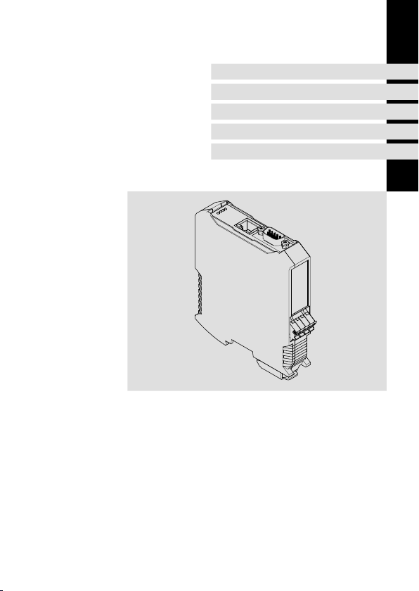
EMF2180IB
Kommunikationsbaugruppe
Communication module
Module de communication
Módulo de comunicación
Modulo di comunicazione
Page 2

Lesen Sie zuerst diese Anleitung, bevor Sie mit den Arbeiten beginnen!
Beachten Sie die enthaltenen Sicherheitshinweise.
Please read these instructions before you start working!
Follow the enclosed safety instructions.
Veuillez lire attentivement cette documentation avant toute action !
Les consignes de sécurité doivent impérativement être respectées.
Lea las instrucciones antes de empezar a trabajar.
Observe las instrucciones de seguridad indicadas.
Prima di usare l’apparecchiatura, leggere le istruzioni contenute in questo
manuale.
Osservare le note di sicurezza.
Page 3
2180FEW001D
Page 4

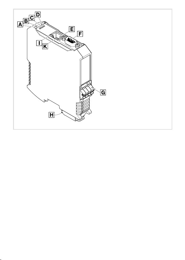
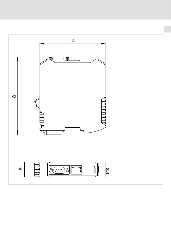
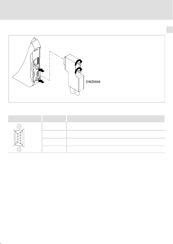
Legende zur Abbildung auf der Ausklappseite
Pos. Beschreibung Ausführliche
Ethernet-Anschluss
Buchse RJ45
CAN-Anschluss
9-polige Sub-D-Buchse
Anschluss für Spannungsversorgung
4-polige Steckerleiste mit Federkraftanschluss
PE-Anschluss
Die gesteckte Kommunikationsbaugruppe ist automatisch mit der Hutschiene verbunden.
Die Hutschiene muss mit PE verbunden sein!
Information
24
21
26
LED-Statusanzeigen zur Diagnose 28
0Abb.0Tab. 0
4
EDKMF2180 DE/EN/FR/ES/IT 3.0
Page 5

Inhalt i
1 Über diese Dokumentation 6. . . . . . . . . . . . . . . . . . . . . . . . . . . . . . . . . . . . . . . . . .
Verwendete Konventionen 7. . . . . . . . . . . . . . . . . . . . . . . . . . . . . . . . . . . . . . . . . .
Verwendete Hinweise 8. . . . . . . . . . . . . . . . . . . . . . . . . . . . . . . . . . . . . . . . . . . . . . .
2 Sicherheitshinweise 10. . . . . . . . . . . . . . . . . . . . . . . . . . . . . . . . . . . . . . . . . . . . . . . .
3 Produktbeschreibung 11. . . . . . . . . . . . . . . . . . . . . . . . . . . . . . . . . . . . . . . . . . . . . . .
Funktion 11. . . . . . . . . . . . . . . . . . . . . . . . . . . . . . . . . . . . . . . . . . . . . . . . . . . . . . . . . .
Bestimmungsgemäße Verwendung 11. . . . . . . . . . . . . . . . . . . . . . . . . . . . . . . . . . .
Lieferumfang 11. . . . . . . . . . . . . . . . . . . . . . . . . . . . . . . . . . . . . . . . . . . . . . . . . . . . . .
Identifikation 12. . . . . . . . . . . . . . . . . . . . . . . . . . . . . . . . . . . . . . . . . . . . . . . . . . . . . .
4 Technische Daten 13. . . . . . . . . . . . . . . . . . . . . . . . . . . . . . . . . . . . . . . . . . . . . . . . . .
Allgemeine Daten und Einsatzbedingungen 13. . . . . . . . . . . . . . . . . . . . . . . . . . .
Schutzisolierung 14. . . . . . . . . . . . . . . . . . . . . . . . . . . . . . . . . . . . . . . . . . . . . . . . . . .
Abmessungen 15. . . . . . . . . . . . . . . . . . . . . . . . . . . . . . . . . . . . . . . . . . . . . . . . . . . . .
5 Mechanische Installation 16. . . . . . . . . . . . . . . . . . . . . . . . . . . . . . . . . . . . . . . . . . . .
6 Elektrische Installation 18. . . . . . . . . . . . . . . . . . . . . . . . . . . . . . . . . . . . . . . . . . . . . .
Umgang mit Steckerleisten 19. . . . . . . . . . . . . . . . . . . . . . . . . . . . . . . . . . . . . . . . . .
EMV-gerechte Verdrahtung 20. . . . . . . . . . . . . . . . . . . . . . . . . . . . . . . . . . . . . . . . . .
Systembus (CAN) anschließen 21. . . . . . . . . . . . . . . . . . . . . . . . . . . . . . . . . . . . . . . .
Ethernet-Anschluss 24. . . . . . . . . . . . . . . . . . . . . . . . . . . . . . . . . . . . . . . . . . . . . . . . .
Spannungsversorgung 26. . . . . . . . . . . . . . . . . . . . . . . . . . . . . . . . . . . . . . . . . . . . . .
7 Inbetriebnahme 27. . . . . . . . . . . . . . . . . . . . . . . . . . . . . . . . . . . . . . . . . . . . . . . . . . .
Vor dem ersten Einschalten 27. . . . . . . . . . . . . . . . . . . . . . . . . . . . . . . . . . . . . . . . . .
8 Diagnose 28. . . . . . . . . . . . . . . . . . . . . . . . . . . . . . . . . . . . . . . . . . . . . . . . . . . . . . . . .
LED-Statusanzeigen 28. . . . . . . . . . . . . . . . . . . . . . . . . . . . . . . . . . . . . . . . . . . . . . .
EDKMF2180 DE/EN/FR/ES/IT 3.0
5
Page 6

1 Über diese Dokumentation
1 Überdiese Dokumentation
Inhalt
Diese Dokumentation enthält ...
ƒ Sicherheitshinweise, die Sie unbedingt beachten müssen;
ƒ Informationen zur mechanischen und elektrischen Installation der
Kommunikationsbaugruppe;
ƒ Informationen zur Inbetriebnahme und Diagnose.
Informationen zur Gültigkeit
Die Informationen in dieser Dokumentation sind gültig für folgende Geräte:
Kommunikationsbaugruppe Typenbezeichnung ab Hardwarestand ab Softwarestand
EthernetCAN EMF2180IB 1x 1x
Zielgruppe
Diese Dokumentation richtet sich an Personen, die die Vernetzung und Fernwartung einer
Maschine projektieren, installieren, in Betrieb nehmen und warten.
Tipp!
Dokumentationen und Software-Updates zu weiteren Lenze Produkten finden
Sie im Internet im Bereich ”Services & Downloads” unter
http://www.Lenze.com
6
EDKMF2180 DE/EN/FR/ES/IT 3.0
Page 7

Über diese Dokumentation
Verwendete Konventionen
Verwendete Konventionen
Diese Dokumentation verwendet folgende Konventionen zur Unterscheidung verschiedener Arten von Information:
Informationsart Auszeichnung Beispiele/Hinweise
Zahlenschreibweise
Dezimaltrennzeichen Punkt Es wird generell der Dezimalpunkt
Symbole
Seitenverweis
verwendet.
Beispiel: 1234.56
Verweis auf eine andere Seite mit zusätzlichen Informationen
Beispiel:16 = siehe Seite 16
1
EDKMF2180 DE/EN/FR/ES/IT 3.0
7
Page 8

1 Über diese Dokumentation
Verwendete Hinweise
Verwendete Hinweise
Um auf Gefahren und wichtige Informationen hinzuweisen, werden in dieser Dokumentation folgende Piktogramme und Signalwörter verwendet:
Sicherheitshinweise
Aufbau der Sicherheitshinweise:
Gefahr!
(kennzeichnet die Art und die Schwere der Gefahr)
Hinweistext
(beschreibt die Gefahr und gibt Hinweise, wie sie vermieden werden kann)
Piktogramm und Signalwort Bedeutung
Gefahr von Personenschäden durch gefährliche elektrische Spannung
Gefahr!
Gefahr!
Stop!
Hinweis auf eine unmittelbar drohende Gefahr, die den
Tod oder schwere Verletzungen zur Folge haben kann,
wenn nicht die entsprechenden Maßnahmen getroffen
werden.
Gefahr von Personenschäden durch eine allgemeine Gefahrenquelle
Hinweis auf eine unmittelbar drohende Gefahr, die den
Tod oder schwere Verletzungen zur Folge haben kann,
wenn nicht die entsprechenden Maßnahmen getroffen
werden.
Gefahr von Sachschäden
Hinweis auf eine mögliche Gefahr, die Sachschäden zur
Folge haben kann, wenn nicht die entsprechenden Maßnahmen getroffen werden.
8
EDKMF2180 DE/EN/FR/ES/IT 3.0
Page 9

Anwendungshinweise
Piktogramm und Signalwort Bedeutung
Über diese Dokumentation
Verwendete Hinweise
1
Hinweis!
Tipp!
Wichtiger Hinweis für die störungsfreie Funktion
Nützlicher Tipp für dieeinfache Handhabung
Verweis auf andere Dokumentation
EDKMF2180 DE/EN/FR/ES/IT 3.0
9
Page 10

2 Sicherheitshinweise
2 Sicherheitshinweise
Gefahr!
Unsachgemäßer Umgang mit der Kommunikationsbaugruppe und dem
Grundgerät kann schwere Personenschäden und Sachschäden verursachen.
Beachten Sie die in der Dokumentation zum Grundgerät enthaltenen
Sicherheitshinweise und Restgefahren.
Stop!
Elektrostatische Entladung
Durch elektrostatische Entladung können elektronische Bauteile innerhalb der
Kommunikationsbaugruppe beschädigt oder zerstört werden.
Mögliche Folgen:
ƒ
Die Kommunikationsbaugruppe ist defekt.
ƒ
Die Feldbus-Kommunikation ist nicht möglich oder fehlerhaft.
Schutzmaßnahmen
ƒ
Befreien Sie sich vor dem Berühren der Baugruppe von elektrostatischen
Aufladungen.
10
EDKMF2180 DE/EN/FR/ES/IT 3.0
Page 11

Produktbeschreibung
Funktion
3 Produktbeschreibung
Funktion
Die Kommunikationsbaugruppe dient mittels Fernwartung zur Parametrierung bzw. Programmierung und Inbetriebnahme der einsetzbaren Geräte.
Bestimmungsgemäße Verwendung
Die Kommunikationsbaugruppe ist mit folgenden Lenze-Geräten einsetzbar:
ƒ Servo Drives 9400
ƒ Inverter Drives 8400
ƒ Servo-Umrichter 9300
ƒ 9300 vector
ƒ 9300 Servo PLC
ƒ Servosystem ECS
ƒ Motorumrichter 8200 motec
ƒ Frequenzumrichter 8200 vector
ƒ Frequenzumrichter 82XX
ƒ Drive PLC
ƒ Klemmenerweiterung 9374
ƒ Bedien-/Anzeigeeinheit (EPM-HXXX)
ƒ I/O-System IP20 (EPM-TXXX)
Lieferumfang
ƒ Kommunikationsbaugruppe EMF2180IB (EthernetCAN)
ƒ Montageanleitung
Tipp!
Weiterführende Informationen zu dieser Kommunikationsbaugruppe finden
Sie im entsprechenden Kommunikationshandbuch.
Die PDF-Datei finden Sie im Internet im Bereich ”Services & Downloads” unter
http://www.Lenze.com
3
EDKMF2180 DE/EN/FR/ES/IT 3.0
11
Page 12
3 Produktbeschreibung
Identifikation
Identifikation
2180FEW099
Typenschlüssel
Gerätereihe
Hardwarestand
Softwarestand
12
33.2180IB 1x 1x
EDKMF2180 DE/EN/FR/ES/IT 3.0
Page 13

Allgemeine Daten und Einsatzbedingungen
Technische Daten
4 Technische Daten
Allgemeine Daten und Einsatzbedingungen
Bereich Werte
Bestell-Bezeichnung EMF2180IB
Kommunikationsmedien (An-
lage)
Anzahl Teilnehmer am CAN-Bus Max. 100
Übertragungsrate
Spannungsversorgung (extern)
über separates Netzteil
Einsatzbedingungen Werte Abweichungen von der Norm
Klimatische Bedingungen
Lagerung 1 K3 nach IEC/EN 60721-3-1 - 10 ... + 60 °C
Transport 2 K3nach IEC/EN 60721-3-2 -10 ... + 70 °C
Schutzart des gesteckten Moduls
Verschmutzungsgrad 2 nach IEC/EN 61800-5-1
CAN (DIN ISO 11898)
Ethernet (100 Base TX, IEEE802.3u)
bei Kommunikation über CAN
– 20 kBit/s
– 50 kBit/s
– 125 kBit/s
– 250 kBit/s
– 500 kBit/s
– 1000 kBit/s
bei Kommunikation über Ethernet
– 10 MBit/s
– 100 MBit/s
18 … 30 VDC, max. 100 mA (nach EN61131-2)
Betrieb 3 K3 nach IEC/EN 60721-3-3 0 ... + 60 °C
IP20
4
EDKMF2180 DE/EN/FR/ES/IT 3.0
13
Page 14
4 Technische Daten
Schutzisolierung
Schutzisolierung
Anschluss Art der Isolierung (nach EN 61800-5-1)
Ethernet Betriebsisolierung
CAN-Bus Betriebsisolierung
Spannungsversorgung Keine Isolierung
2180FEW001F
14
EDKMF2180 DE/EN/FR/ES/IT 3.0
Page 15
Abmessungen
Technische Daten
Abmessungen
4
a 117 mm
b 99 mm
e 22.5 mm
EDKMF2180 DE/EN/FR/ES/IT 3.0
2180FEW001B
15
Page 16
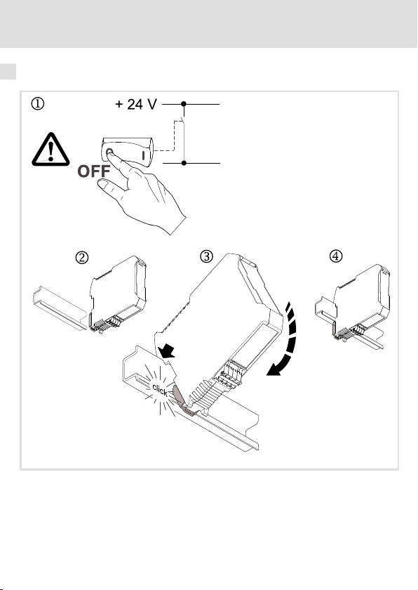
5 Mechanische Installation
5 MechanischeI nstallation
Montage
16
2181FEW002B
EDKMF2180 DE/EN/FR/ES/IT 3.0
Page 17
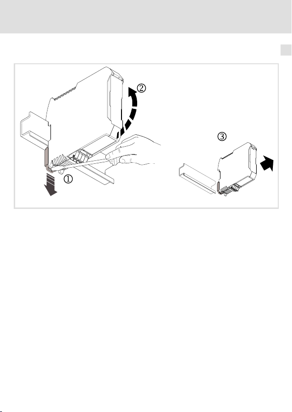
Demontage
Mechanische Installation 5
2181FEW001E
EDKMF2180 DE/EN/FR/ES/IT 3.0
17
Page 18
6 Elektrische Installation
6 ElektrischeInstal lation
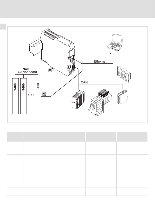
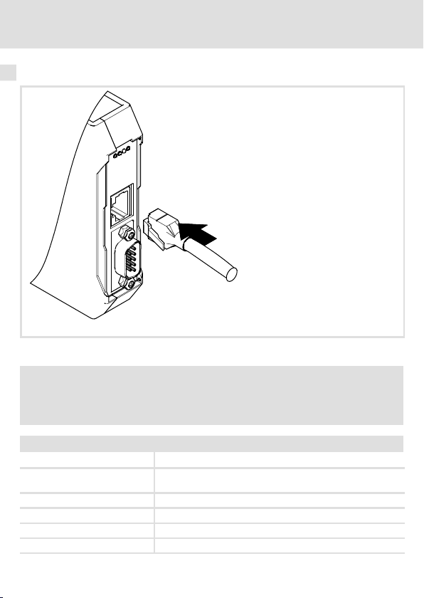
Installationsschritte
Schritt Tätigkeit Anschluss
1. Verbindung zum CAN-Bus herstellen:
Sub-D-Stecker (”EWZ0046”, siehe Zubehör)
in die Kommunikationsbaugruppe stecken.
2.
Folgende Komponenten über Ethernet miteinander verbinden:
Kommunikationsbaugruppe
PC
Servo Drives 9400
weitere Ethernet-Teilnehmer
3. Spannungsversorgung an die Steckerleiste
anschließen
(siehe Grafik)
21
26
2180FEW008
Zusätzliche Information
24
18
EDKMF2180 DE/EN/FR/ES/IT 3.0
Page 19
Umgang mit Steckerleisten
Stop!
Um Steckerleisten und Kontakte nicht zu beschädigen:
ƒ
Steckerleisten nur aufstecken / abziehen wenn der Antriebsregler vom
Netz getrennt ist.
ƒ
Steckerleisten erst verdrahten, dann aufstecken.
ƒ
Nicht belegte Steckerleisten ebenfalls aufstecken.
Gebrauch der Steckerleiste mit Federkraftanschluss
Elektrische Installation
Umgang mit Steckerleisten
E82ZAFX013
6
EDKMF2180 DE/EN/FR/ES/IT 3.0
19
Page 20

6 Elektrische Installation
EMV-gerechte Verdrahtung
EMV-gerechte Verdrahtung
Für eine EMV-gerechte Verdrahtung beachten Sie folgende Punkte:
Hinweis!
ƒ
Steuer-/Datenleitungen getrennt von Motorleitungen verlegen.
ƒ
Legen Sie die Schirme der Steuer-/Datenleitungen bei digitalen Signalen
beidseitig
ƒ
ƒ
Vorgehensweise bei der Verdrahtung
1. Bustopologie einhalten, deshalb keine Stichleitungen verwenden.
2. Hinweise und Verdrahtungsvorschriften in den Unterlagen zum Steuerungssystem
beachten.
3. Nur Kabel verwenden, die den aufgeführten Spezifikationen entsprechen (22).
4. Zulässige Busleitungslänge einhalten (23)
5. Hinweise zur Spannungsversorgung der Kommunikationsbaugruppebeachten
(26).
6. Busabschluss-Widerstände von 120Ωam physikalisch ersten und letzten
Busteilnehmer aktivieren.
auf.
Zur Vermeidung von Potenzialdifferenzen zwischen den
Kommunikationsteilnehmern eine Ausgleichsleitung mit einem
Querschnitt von mindestens 16 mm2einsetzen (Bezug: PE).
Beachten Sie die weiteren Hinweise zur EMV-gerechtenVerdrahtung in der
Dokumentation des Grundgerätes.
.
20
EDKMF2180 DE/EN/FR/ES/IT 3.0
Page 21
Systembus (CAN) anschließen
1
6
5
9
Belegung der Sub-D-Steckerleiste
Ansicht Pin Belegung
1, 4, 5, 6, 8, 9 -
2 CAN-LO
3 CAN-GND
7 CAN-HI
Elektrische Installation
Systembus (CAN) anschließen
2180FEW001K
6
EDKMF2180 DE/EN/FR/ES/IT 3.0
21
Page 22
6 Elektrische Installation
L
EWZ0046
OFF
ON
OFF
ON
ON
OFF
ð
ð
ð
ð
OUTIN IN IN
On
Off
On
120 120
120
L
EWZ0046
L
EWZ0046
L
EWZ0046
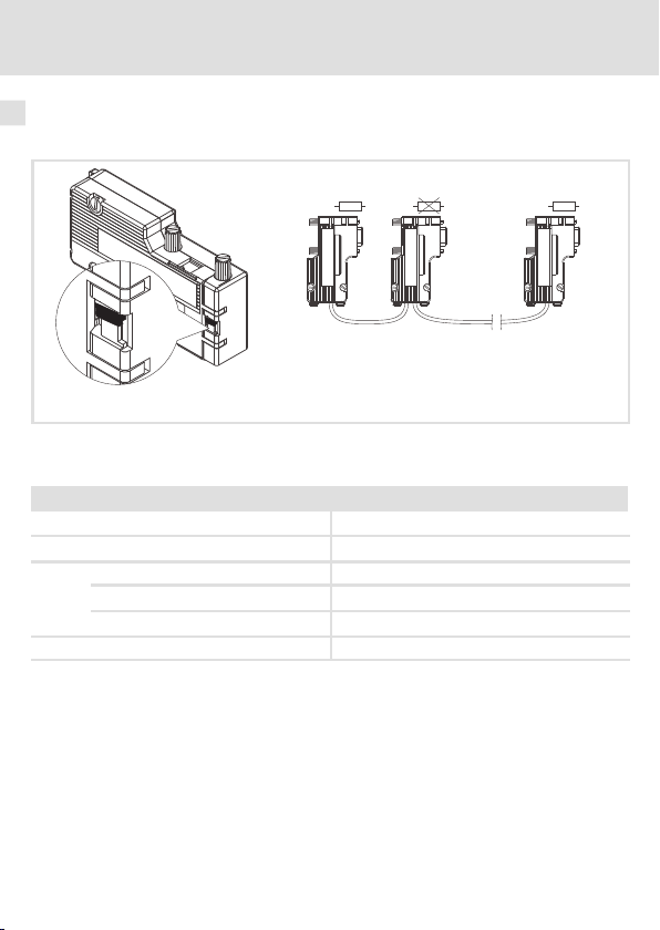
Systembus (CAN) anschließen
Der CAN-Bus muss durch Widerstände (120Ω) zwischen CAN-LOW und CAN-HIGH abgeschlossen sein. Der Sub-D-Stecker mit integriertem Abschlusswiderstand (Bestell-Nr.
EWZ0046, nicht im Lieferumfang enthalten) entspricht der Empfehlung DS 102-1 von CiA.
2181FEW004
Spezifikation des Übertragungskabels
Wir empfehlen CAN-Kabel nach ISO 11898-2 zu verwenden:
CAN-Kabel nach ISO 11898-2
Kabeltyp Paarverseilt mit Abschirmung
Impedanz
Leitungswiderstand/-querschnitt
Kabellänge≤300 m≤70 mΩ/m / 0.25 … 0.34 mm2(AWG22)
Kabellänge 301 … 1000 m
Signallaufzeit
Beachten Sie die Informationen zur Busleitungslänge(
120Ω(95 ... 140Ω)
≤
40 mΩ/m / 0.5 mm2(AWG20)
≤
5 ns/m
23)
!
22
EDKMF2180 DE/EN/FR/ES/IT 3.0
Page 23
Elektrische Installation
Systembus (CAN) anschließen
Busleitungslänge
Halten Sie die zulässigen Leitungslängen unbedingt ein.
1. Überprüfen Sie die Einhaltung der Gesamt-Leitungslänge in Tab. 1.
Durch die Übertragungsrate ist die Gesamt-Leitungslänge festgelegt.
Übertragungsrate [kBit/s] Max. Buslänge [m]
20 3600
50 1400
125 550
250 250
500 110
1000 20
Tab. 1 Gesamt-Leitungslänge
2. Überprüfen Sie die Einhaltung der Segment-Leitungslänge in Tab. 2.
Die Segment-Leitungslänge wird durch den verwendeten Leitungsquerschnitt und die Teilnehmeranzahl festgelegt. Ohne Repeater ist die Segment-Leitungslänge gleich der Gesamt-Leitungslänge.
Leitungsquerschnitt
2
Teilnehmer
2 240 m 430 m 650 m 940 m
5 230 m 420 m 640 m 920 m
10 230 m 410 m 620 m 900 m
20 210 m 390 m 580 m 850 m
32 200 m 360 m 550 m 800 m
63 170 m 310 m 470 m 690 m
100 150 m 270 m 410 m 600 m
Tab. 2 Segment-Leitungslänge
0.25 mm
3. Vergleichen Sie die beiden ermittelten Werte miteinander.
Wenn der aus Tab. 2 ermittelte Wert kleiner als die zu realiserende Gesamt-Leitungslänge
aus Tab. 1 sein sollte, müssen Repeater eingesetzt werden. Repeater unterteilen die Gesamt-Leitungslänge in Segmente.
0.5 mm
2
0.75 mm
2
1.0 mm
2
6
EDKMF2180 DE/EN/FR/ES/IT 3.0
23
Page 24
6 Elektrische Installation
Ethernet-Anschluss
Ethernet-Anschluss
Spezifikation des Übertragungskabels
Hinweis!
Verwenden Sie ausschließlichKabel, die den aufgeführten Spezifikationen
entsprechen.
2181FEW004A
Spezifikation des Ethernet-Kabels
Ethernet-Standard Standard Ethernet (nach IEEE 802.3), 100Base-TX (Fast Ethernet)
Kabeltyp S/FTP (Screened Foiled Twisted Pair, ISO/IEC 11801 oder
Dämpfung 23.2 dB (bei 100 MHz und je 100 m)
Nebensprechdämpfung 24 dB (bei100 MHz und je 100 m)
Rückflussdämpfung 10 dB (je 100 m)
Wellenwiderstand
24
EN 50173), CAT 5e
100
Ω
EDKMF2180 DE/EN/FR/ES/IT 3.0
Page 25
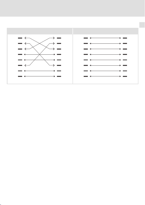
Elektrische Installation
1Tx+ Tx+1
2Tx- Tx-2
3Rx+ Rx+3
4 4
5 5
6Rx- Rx-6
7 7
8 8
1Tx+ Tx+1
2Tx- Tx-2
3Rx+ Rx+3
4 4
5 5
6Rx- Rx-6
7 7
8 8
Ethernet-Anschluss
Pin-Belegung
100BaseTX - CrossOver Cable 100BaseTX - Standard Patch Cable
Verwendung der Kabel
ƒ Das ”100BaseTX - CrossOver Cable” wird bei direkter Kopplung von PC und der
Kommunikationsbaugruppe verwendet.
ƒ Das ”100BaseTX - Standard Patch Cable” wird bei Verwendung von Hubs und
Switches eingesetzt.
6
E94YCEI002
EDKMF2180 DE/EN/FR/ES/IT 3.0
25
Page 26
6 Elektrische Installation
Spannungsversorgung
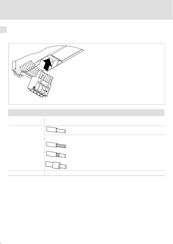
Spannungsversorgung
Daten der Anschlussklemmen
Daten der Anschlussklemmen
Elektrischer An-
schluss
Anschlussmöglichkei-
ten
Abisolierlänge 10 mm
Steckerleiste mit Federkraftanschluss
starr: 2.5 mm2(AWG 12)
flexibel:
ohne Aderendhülse
2.5 mm2(AWG 12)
mit Aderendhülse, ohne Kunststoffhülse
2.5 mm2(AWG 12)
mit Aderendhülse, mit Kunststoffhülse
2.5 mm2(AWG 12)
2181FEW001G
26
EDKMF2180 DE/EN/FR/ES/IT 3.0
Page 27

Vor dem ersten Einschalten
7 Inbetriebnahme
Vor dem ersten Einschalten
Stop!
Überprüfen Sie vor dem Einschalten der Netzspannung die gesamte
Verdrahtung auf Vollständigkeit, Kurzschluss und Erdschluss.
Weiterführende Informationen zur Inbetriebnahme dieser
Kommunikationsbaugruppe finden Sie im Kommunikationshandbuch
Fernwartung.
Inbetriebnahme
7
EDKMF2180 DE/EN/FR/ES/IT 3.0
27
Page 28
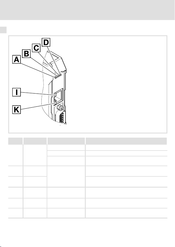
Diagnose
LED-Statusanzeigen
8 Diagnose
LED-Statusanzeigen
Pos. Farbe Zustand Beschreibung
gelb
(B)
rot
(E)
grün RUN-LED
(R)
grün an 2180 EthernetCAN wird mit Spannung versorgt.
(P)
grün an Die Verbindung zum Ethernet-Netzwerk besteht
grün an oder blinkt
aus Übertragungsrate: 10 MBit/s
an
blinkt Die IP-Adresse der Baugruppe ist noch nicht zuge-
siehe 29
Übertragungsrate: 100 MBit/s
ordnet; sie wird momentan ermittelt.
ERR-LED
(LINK).
Es werden Daten gesendet oder empfangen
(ACTIVITY).
2180FEW0 01H
28
EDKMF2180 DE/EN/FR/ES/IT 3.0
Page 29
LED
Pos. Farbe / Zustand
/
aus
grün
rot
rot
Beschreibung
Verbindung zum Master nicht aufgebaut.
CANopen Zustand (”Z”)
CANopen Fehler (”F”)
Z
: Bus Off
Diagnose
LED-Statusanzeigen
blinkt schnell (flackern)
blinkt (grün) im0 .2 s-Takt
blinkt (grün) im0 .2 s-Takt
blinkt (rot) 1 x, 1 s aus
blinkt (grün) im0 .2 s-Takt
blinkt (rot) 2 x, 1 s aus
an (grün)
an (grün)
blinkt (rot) 1 x, 1 s aus
an (grün)
blinkt rot 2 x ,1 saus
an (grün)
3 x blinkt rot, 1 saus
blinkt (grün) im1 s-Takt
blinkt (grün) im1 s-Takt
blinkt (rot) 1 x, 1 s aus
blinkt (grün) im1 s-Takt
blinkt rot 2 x, 1 saus
EDKMF2180 DE/EN/FR/ES/IT 3.0
Automatische Übertragungsratenerkennung ist aktiv.
Z
: Pre-Operational,F: keine
Z
: Pre-Operational,F: Warning Limit reached
Z
: Pre-Operational,F: Node Guard Event
Z
: Operational,F: keine
Z
: Operational,F: Warning Limit reached
Z
: Operational,F: Node Guard Event
Z
: Operational,F: Sync Message Error
Z
: Stopped,F: keine
Z
: Stopped,F: Warning Limit reached
Z
: Stopped,F: Node Guard Event
29
Page 30

Legend for fold-out page
Pos. Description Detailed
Ethernet connection
RJ45 socket
CAN connection
9-pin Sub-D socket
Connection for voltage supply
4-pin plug connector with spring connection
PE connection
The plugged communication moduleis automatically connected to the
DIN rail.
The DIN rail must be connected to PE!
information
50
47
52
LED status displays for diagnostics 54
0Fig.0Tab. 0
30
EDKMF2180 DE/EN/FR/ES/IT 3.0
Page 31

Contents i
1 About this documentation 32. . . . . . . . . . . . . . . . . . . . . . . . . . . . . . . . . . . . . . . . . . .
Conventions used 33. . . . . . . . . . . . . . . . . . . . . . . . . . . . . . . . . . . . . . . . . . . . . . . . . .
Notes used 34. . . . . . . . . . . . . . . . . . . . . . . . . . . . . . . . . . . . . . . . . . . . . . . . . . . . . . . .
2 Safety instructions 36. . . . . . . . . . . . . . . . . . . . . . . . . . . . . . . . . . . . . . . . . . . . . . . . .
3 Product description 37. . . . . . . . . . . . . . . . . . . . . . . . . . . . . . . . . . . . . . . . . . . . . . . . .
Function 37. . . . . . . . . . . . . . . . . . . . . . . . . . . . . . . . . . . . . . . . . . . . . . . . . . . . . . . . .
Application as directed 37. . . . . . . . . . . . . . . . . . . . . . . . . . . . . . . . . . . . . . . . . . . . . .
Scope of supply 37. . . . . . . . . . . . . . . . . . . . . . . . . . . . . . . . . . . . . . . . . . . . . . . . . . . .
Identification 38. . . . . . . . . . . . . . . . . . . . . . . . . . . . . . . . . . . . . . . . . . . . . . . . . . . . . .
4 Technical data 39. . . . . . . . . . . . . . . . . . . . . . . . . . . . . . . . . . . . . . . . . . . . . . . . . . . . .
General data and operating conditions 39. . . . . . . . . . . . . . . . . . . . . . . . . . . . . . .
Protective insulation 40. . . . . . . . . . . . . . . . . . . . . . . . . . . . . . . . . . . . . . . . . . . . . . . .
Dimensions 41. . . . . . . . . . . . . . . . . . . . . . . . . . . . . . . . . . . . . . . . . . . . . . . . . . . . . . .
5 Mechanical installation 42. . . . . . . . . . . . . . . . . . . . . . . . . . . . . . . . . . . . . . . . . . . . .
6 Electrical installation 44. . . . . . . . . . . . . . . . . . . . . . . . . . . . . . . . . . . . . . . . . . . . . . .
Use of plug connectors 45. . . . . . . . . . . . . . . . . . . . . . . . . . . . . . . . . . . . . . . . . . . . . .
Wiring according to EMC 46. . . . . . . . . . . . . . . . . . . . . . . . . . . . . . . . . . . . . . . . . . . .
Connection of system bus (CAN) 47. . . . . . . . . . . . . . . . . . . . . . . . . . . . . . . . . . . . . .
Ethernet connection 50. . . . . . . . . . . . . . . . . . . . . . . . . . . . . . . . . . . . . . . . . . . . . . . .
Voltage supply 52. . . . . . . . . . . . . . . . . . . . . . . . . . . . . . . . . . . . . . . . . . . . . . . . . . . . .
7 Commissioning 53. . . . . . . . . . . . . . . . . . . . . . . . . . . . . . . . . . . . . . . . . . . . . . . . . . . .
Before switching on 53. . . . . . . . . . . . . . . . . . . . . . . . . . . . . . . . . . . . . . . . . . . . . . . .
8 Diagnostics 54. . . . . . . . . . . . . . . . . . . . . . . . . . . . . . . . . . . . . . . . . . . . . . . . . . . . . . .
LED status displays 54. . . . . . . . . . . . . . . . . . . . . . . . . . . . . . . . . . . . . . . . . . . . . . . .
EDKMF2180 DE/EN/FR/ES/IT 3.0
31
Page 32

1 About this documentation
1 Aboutthis documentation
Contents
This documentation provides ...
ƒ Safety instructions that must be observed;
ƒ Information about the mechanical and electrical installation of the communication
module;
ƒ Information about commissioning and diagnostics;
Validity information
The information given in this documentation is valid for the following devices:
Communication module Type designation from hardware
EthernetCAN EMF2180IB 1x 1x
Target group
This documentation addresses to persons who project, install, commission, and maintain
the networking and remote maintenance of a machine.
Tip!
Documentation and software updates for further Lenze products can be found
on the Internet in the ”Services & Downloads” area under
http://www.Lenze.com
version
from software
version
32
EDKMF2180 DE/EN/FR/ES/IT 3.0
Page 33

About this documentation
Conventions used
Conventions used
This documentation uses the following conventions to distinguish between differenttypes
of information:
Type of information Identification Examples/notes
Numbers
Decimal separator Point The decimal point is used throughout
Symbols
Page reference
this documentation.
Example: 1234.56
Reference to another page with
additional information
Example:16 = see page 16
1
EDKMF2180 DE/EN/FR/ES/IT 3.0
33
Page 34

1 About this documentation
Notes used
Notes used
The following pictographs and signal words are used in this documentation to indicate
dangers and important information:
Safety instructions
Structure of safety instructions:
Danger!
(characterises the type and severity of danger)
Note
(describes the danger and gives information about how to prevent dangerous
situations)
Pictograph and signal word Meaning
Danger of personal injury through dangerous electrical
voltage.
Danger!
Danger!
Stop!
Reference to an imminent danger that mayresult in
death or serious personal injury if the corresponding
measures are not taken.
Danger of personal injury through a general source of
danger.
Reference to an imminent danger that mayresult in
death or serious personal injury if the corresponding
measures are not taken.
Danger of property damage.
Reference to a possible danger that may result in
property damage if the corresponding measures are not
taken.
34
EDKMF2180 DE/EN/FR/ES/IT 3.0
Page 35

Application notes
Pictograph and signal word Meaning
About this documentation
Notes used
1
Note!
Tip!
Important note to ensure troublefree operation
Useful tip for simple handling
Reference to another documentation
EDKMF2180 DE/EN/FR/ES/IT 3.0
35
Page 36

2 Safety instructions
2 Safetyin structions
Danger!
Inappropriate handling of the communication module and the basic device can
cause serious injuries to persons and damage to material assets.
Observe the safety instructions and residual hazards described in the
documentation for the standard device.
Stop!
Electrostatic discharge
Electronic components of the communication module can be damaged or
destroyed through electrostatic discharge.
Possible consequences:
ƒ
The communication module is defective.
ƒ
Fieldbus communication is not possible or faulty.
Protective measures
ƒ
Free yourself from any electrostatic charge before you touch the module.
36
EDKMF2180 DE/EN/FR/ES/IT 3.0
Page 37

Product description
Function
3 Productdescription
Function
The communication module is used for setting parameters during remote maintenance or
programming and commissioning the usable devices:
Application as directed
The communication module can be used with the following Lenze devices:
ƒ Servo Drives 9400
ƒ Inverter Drives 8400
ƒ 9300 servo inverter
ƒ 9300 vector
ƒ 9300 Servo PLC
ƒ ECS servo system
ƒ 8200 motec motor inverter
ƒ 8200 vector frequency inverter
ƒ 82XX frequency inverter
ƒ Drive PLC
ƒ Terminal extension 9374
ƒ Control / display unit (EPM-HXXX)
ƒ I/O system IP20 (EPM-TXXX)
Scope of supply
ƒ Communication module EMF2180IB (EthernetCAN)
ƒ Mounting Instructions
Tip!
Further information about this communication module can be found in the
corresponding communication manual.
The pdf file can be found on the Internet in the ”Services & Downloads” area
under
http://www.Lenze.com
3
EDKMF2180 DE/EN/FR/ES/IT 3.0
37
Page 38

3 Product description
Identification
Identification
2180FEW099
Type code
Device series
Hardware version
Software version
38
33.2180IB 1x 1x
EDKMF2180 DE/EN/FR/ES/IT 3.0
Page 39

General data and operating conditions
Technical data
4 Technical data
General data and operating conditions
Range Values
Order designation EMF2180IB
Communication media (system) CAN (DIN ISO 11898)
Number of nodes at theCAN
bus
Baud rate
Voltage supply (external) via
separate power supply
Operating conditions Values Deviations from the standard
Climatic conditions
Storage 1 K3 to IEC/EN 60721-3-1 - 10 ... + 60°C
Transport 2 K3acc. to IEC/EN 60721-3-2 - 10 ... + 70 °C
Enclosure of attached module IP20
Degree of pollution 2 acc. to IEC/EN 61800-5-1
Operation 3 K3 acc. to IEC/EN 60721-3-3 0 ... + 60 °C
Ethernet (100 Base TX, IEEE802.3u)
Max. 100
when communicating via CAN
– 20 kbit/s
– 50 kbit/s
– 125 kbit/s
– 250 kbit/s
– 500 kBit/s
– 1000 kbps
when communicating via Ethernet
– 10 Mbit/s
– 100 Mbit/s
18 … 30 VDC, max. 100 mA (in accordancewith EN 61131-2)
4
EDKMF2180 DE/EN/FR/ES/IT 3.0
39
Page 40

4 Technical data
Protective insulation
Protective insulation
Terminal Type of insulation (according to EN 61800-5-1)
Ethernet Functional insulation
CAN bus Functional insulation
Voltage supply No insulation
2180FEW001F
40
EDKMF2180 DE/EN/FR/ES/IT 3.0
Page 41

Dimensions
Technical data
Dimensions
4
a 117 mm
b 99 mm
e 22.5 mm
EDKMF2180 DE/EN/FR/ES/IT 3.0
2180FEW001B
41
Page 42

5 Mechanical installation
5 Mechanical installation
Mounting
42
2181FEW002B
EDKMF2180 DE/EN/FR/ES/IT 3.0
Page 43

Dismounting
Mechanical installation 5
2181FEW001E
EDKMF2180 DE/EN/FR/ES/IT 3.0
43
Page 44

6 Electrical installation
6 Electricalinstall ation
Installation steps
Step Activity Terminal
1. Establish a connection to the CAN bus:
Plug the Sub-D plug (”EWZ0046”, see
accessories) into the communication
module.
2.
Connect the following components via
Ethernet with each other:
Communication module
PC
Servo Drives 9400
Other Ethernet nodes
3. Connect voltage supply to the plug
connector
(see graphic)
47
52
Additional
information
50
2180FEW008
44
EDKMF2180 DE/EN/FR/ES/IT 3.0
Page 45

Electrical installation
Use of plug connectors
Stop!
Observe the following to prevent any damage to plug connectors and
contacts:
ƒ
Only pug in / unplug the plug connectors when the controller is
disconnected from the mains.
ƒ
Wire the plug connectors before plugging them in.
ƒ
Unused plug connectors must also be plugged in.
Use of plug connectors with spring connection
Use of plug connectors
6
E82ZAFX013
EDKMF2180 DE/EN/FR/ES/IT 3.0
45
Page 46

6 Electrical installation
Wiring according to EMC
Wiring according to EMC
For wiring according to EMC requirements observe the following points:
Note!
ƒ
Separate control cables/data lines from motor cables.
ƒ
Connect the shields of control cables/data lines
digital signals.
ƒ
Use an equalizing conductor with a cross-section of at least 16 mm
(reference: PE) to avoid potential differences between the bus nodes.
ƒ
Observe the other notes concerning EMC-compliant wiring given in the
documentation for the standard device.
Wiring procedure
1. Observe the bus topology, do not use any stubs.
2. Follow the wiring notes given in the documentation for the control system.
3. Only use cables that correspond to the listed specifications (48).
4. Observe the permissible bus cable length (49)
5. Observe the voltage supply notes for the communication module(52).
6. Activate bus terminating resistors of 120Ωat the physically first and last node.
.
at both ends
in the case of
2
46
EDKMF2180 DE/EN/FR/ES/IT 3.0
Page 47

Connection of system bus (CAN)
1
6
5
9
Assignment of the Sub-D plug connector
View Pin Assignment
1, 4, 5, 6, 8, 9 -
2 CAN-LO
3 CAN-GND
7 CAN-HI
Electrical installation
Connection of system bus (CAN)
2180FEW001K
6
EDKMF2180 DE/EN/FR/ES/IT 3.0
47
Page 48

6 Electrical installation
L
EWZ0046
OFF
ON
OFF
ON
ON
OFF
ð
ð
ð
ð
OUTIN IN IN
On
Off
On
120 120
120
L
EWZ0046
L
EWZ0046
L
EWZ0046
Connection of system bus (CAN)
Between CAN_LOW and CAN-HIGH the CAN bus has to be terminated by resistors (120Ω).
The Sub-D plug with an integrated terminating resistor (order no. EWZ0046, not included
in the scope of supply) complies with the recommendation DS 102-1 of CiA.
2181FEW004
Specification of the transmissioncable
We recommend the use of CAN cables in accordance with ISO 11898-2:
CAN cable in accordance with ISO 11898-2
Cable type Paired with shielding
Impedance
Cable resistance/cross-section
Cable length≤300 m≤70 mΩ/m / 0.25 … 0.34 mm2(AWG22)
Cable length 301 …1000 m
Signal propagation delay
Observe the information on the bus cable length
120Ω(95 ... 140Ω)
≤
40 mΩ/m / 0.5 mm2(AWG20)
≤
5 ns/m
(49)
!
48
EDKMF2180 DE/EN/FR/ES/IT 3.0
Page 49

Electrical installation
Connection of system bus (CAN)
Bus cable length
It is absolutely necessary to comply with the permissible cable lengths.
1. Check the compliance with the total cable length in Tab. 1.
The total cable length is determined by the baud rate.
Baud rate [kbit/s] Max. bus length [m]
20 3600
50 1400
125 550
250 250
500 110
1000 20
Tab. 1 Total cable length
2. Check the compliance with the segment cable length in Tab. 2.
The segment cable length is determined by the cable cross-sectionusedandby the number
of nodes.Withoutrepeatersthe segment cablelengthcorrespondstothetotalcablelength.
Cable cross-section
2
Nodes
2 240 m 430 m 650 m 940 m
5 230 m 420 m 640 m 920 m
10 230 m 410 m 620 m 900 m
20 210 m 390 m 580 m 850 m
32 200 m 360 m 550 m 800 m
63 170 m 310 m 470 m 690 m
100 150 m 270 m 410 m 600 m
Tab. 2 Segment cable length
0.25 mm
3. Compare both values.
If the value given in Tab. 2 is smaller than the required total cable length from Tab. 1,
repeaters must be used. Repeaters divide the total cable length into segments.
0.5 mm
2
0.75 mm
2
1.0 mm
2
6
EDKMF2180 DE/EN/FR/ES/IT 3.0
49
Page 50

6 Electrical installation
Ethernet connection
Ethernet connection
2181FEW004A
Specification of the transmissioncable
Note!
Only use cables complying with the below specifications.
Specification of the Ethernet cable
Ethernet standard Standard Ethernet (in accordance with IEEE 802.3), 100Base-TX
Cable type S/FTP (Screened Foiled Twisted Pair, ISO/IEC 11801 or EN 50173),
Damping 23.2 dB (at 100 MHz and per 100 m)
Crosstalk damping 24 dB (at 100 MHz and per 100 m)
Return loss 10 dB (per 100 m)
Surge impedance
(Fast Ethernet)
CAT 5e
100
Ω
50
EDKMF2180 DE/EN/FR/ES/IT 3.0
Page 51

Electrical installation
1Tx+ Tx+1
2Tx- Tx-2
3Rx+ Rx+3
4 4
5 5
6Rx- Rx-6
7 7
8 8
1Tx+ Tx+1
2Tx- Tx-2
3Rx+ Rx+3
4 4
5 5
6Rx- Rx-6
7 7
8 8
Ethernet connection
Pin assignment
100BaseTX - CrossOver Cable 100BaseTX - Standard Patch Cable
Use of cables
ƒ The ”100BaseTX - CrossOver Cable” is used for direct coupling of PC and
communication module.
ƒ The ”100BaseTX - Standard Patch Cable” is used in conjunction with hubs and
switches.
6
E94YCEI002
EDKMF2180 DE/EN/FR/ES/IT 3.0
51
Page 52

6 Electrical installation
Voltage supply
Voltage supply
Terminal data
Terminal data
Electrical connection Plug connector with spring connection
Possible connections
Stripping length 10 mm
rigid: 2.5 mm2(AWG 12)
flexible:
without wire end ferrule
2.5 mm2(AWG 12)
with wire end ferrule, without plastic sleeve
2.5 mm2(AWG 12)
with wire end ferrule, with plastic sleeve
2.5 mm2(AWG 12)
2181FEW001G
52
EDKMF2180 DE/EN/FR/ES/IT 3.0
Page 53

Commissioning
Before switching on
7 Commissioning
Before switching on
Stop!
Prior to switching on the mains voltage, check the wiring for completeness,
short-circuit and earth fault.
Further information on how to commission this communication module can
be found in the maintenance communication manual.
7
EDKMF2180 DE/EN/FR/ES/IT 3.0
53
Page 54

Diagnostics
LED status displays
8 Diagnostics
LED status displays
Pos. Colour State Description
Yellow
(B)
Red
(E)
Green RUN LED
(R)
Green On 2180 EthernetCAN is supplied with power.
(P)
green on The connection to the Ethernet network is
green On or blinking
Off Baud rate: 10 Mbits/s
On
Blinking The IP address of the module is not assigned yet; it
See 55
Baud rate: 100 Mbits/s
is currently being detected.
ERR LED
established (LINK).
Data are being transmitted or received
(ACTIVITY).
2180FEW001H
54
EDKMF2180 DE/EN/FR/ES/IT 3.0
Page 55

LED
Pos. Colour / status
+
off Connection to master not established.
green
red
red
Description
CANopen status (”Z”)
CANopen error (”F”)
Z
: Bus off
Diagnostics
LED status displays
blinking fast (jittering)
blinking (green) every 0.2 s
blinking (green) every 0.2 s
blinking (red) 1 x, 1 s off
blinking (green) every 0.2 s
blinking (red) 2 x, 1 s off
on (green)
on (green)
blinking (red) 1 x, 1 s off
on (green)
blinking red 2 x, 1 s off
on (green)
3 x blinking red, 1 s off
blinking (green) once per
second
blinking (green) once per
second
blinking (red) 1 x, 1 s off
blinking (green) once per
second
blinking red 2 x, 1 s off
EDKMF2180 DE/EN/FR/ES/IT 3.0
Automatic baud rate recognition is active.
Z
: Pre-Operational,F: None
Z
: Pre-Operational,F: Warning limit reached
Z
: Pre-Operational,F: Node guard event
Z
: Operational,F: None
Z
: Operational,F: Warning limit reached
Z
: Operational,F: Node guard event
Z
: Operational,F: Sync message error
Z
: Stopped,F: None
Z
: Stopped,F: Warning limit reached
Z
: Stopped,F: Node guard event
55
Page 56

Légende de l’illustration de la page dépliante
Pos. Description Informations
Raccordement Ethernet
Prise RJ45
Raccordement CAN
Connecteur Sub-D femelle9 broches
Raccordement de l’alimentation
Bornier à lame ressort 4 bornes
Raccordement PE
Le module de communication enfiché est automatiquement en contact
avec le rail profilé.
Le rail profilé doit êtrerelié à la terre (PE) !
détaillées
76
73
78
Affichages d’état par LEDà des fins de diagnostic 80
0Fig.0Tab. 0
56
EDKMF2180 DE/EN/FR/ES/IT 3.0
Page 57

Sommaire i
1 Présentation du document 58. . . . . . . . . . . . . . . . . . . . . . . . . . . . . . . . . . . . . . . . . . .
Conventions utilisées 59. . . . . . . . . . . . . . . . . . . . . . . . . . . . . . . . . . . . . . . . . . . . . . .
Consignes utilisées 60. . . . . . . . . . . . . . . . . . . . . . . . . . . . . . . . . . . . . . . . . . . . . . . . .
2 Consignes de sécurité 62. . . . . . . . . . . . . . . . . . . . . . . . . . . . . . . . . . . . . . . . . . . . . . .
3 Description du produit 63. . . . . . . . . . . . . . . . . . . . . . . . . . . . . . . . . . . . . . . . . . . . . .
Fonction 63. . . . . . . . . . . . . . . . . . . . . . . . . . . . . . . . . . . . . . . . . . . . . . . . . . . . . . . . .
Utilisation conforme à la fonction 63. . . . . . . . . . . . . . . . . . . . . . . . . . . . . . . . . . . . .
Equipement livré 63. . . . . . . . . . . . . . . . . . . . . . . . . . . . . . . . . . . . . . . . . . . . . . . . . . .
Identification 64. . . . . . . . . . . . . . . . . . . . . . . . . . . . . . . . . . . . . . . . . . . . . . . . . . . . . .
4 Spécifications techniques 65. . . . . . . . . . . . . . . . . . . . . . . . . . . . . . . . . . . . . . . . . . .
Caractéristiques générales et conditions d’utilisation 65. . . . . . . . . . . . . . . . . . . .
Isolement de protection 66. . . . . . . . . . . . . . . . . . . . . . . . . . . . . . . . . . . . . . . . . . . . .
Encombrements 67. . . . . . . . . . . . . . . . . . . . . . . . . . . . . . . . . . . . . . . . . . . . . . . . . . .
5 Installation mécanique 68. . . . . . . . . . . . . . . . . . . . . . . . . . . . . . . . . . . . . . . . . . . . . .
6 Installation électrique 70. . . . . . . . . . . . . . . . . . . . . . . . . . . . . . . . . . . . . . . . . . . . . . .
Utilisation des borniers 71. . . . . . . . . . . . . . . . . . . . . . . . . . . . . . . . . . . . . . . . . . . . . .
Câblage conforme CEM 72. . . . . . . . . . . . . . . . . . . . . . . . . . . . . . . . . . . . . . . . . . . . . .
Raccordement du Bus Système CAN 73. . . . . . . . . . . . . . . . . . . . . . . . . . . . . . . . . . .
Raccordement Ethernet 76. . . . . . . . . . . . . . . . . . . . . . . . . . . . . . . . . . . . . . . . . . . . .
Alimentation 78. . . . . . . . . . . . . . . . . . . . . . . . . . . . . . . . . . . . . . . . . . . . . . . . . . . . . .
7 Mise en service 79. . . . . . . . . . . . . . . . . . . . . . . . . . . . . . . . . . . . . . . . . . . . . . . . . . . .
Avant la première mise sous tension 79. . . . . . . . . . . . . . . . . . . . . . . . . . . . . . . . . . .
8 Diagnostic 80. . . . . . . . . . . . . . . . . . . . . . . . . . . . . . . . . . . . . . . . . . . . . . . . . . . . . . . .
Affichages d’état par LED 80. . . . . . . . . . . . . . . . . . . . . . . . . . . . . . . . . . . . . . . . . . .
EDKMF2180 DE/EN/FR/ES/IT 3.0
57
Page 58

1 Présentation du document
1 Présentationdu document
Contenu
La présente documentation contient ...
ƒ des consignes de sécurité qui doivent impérativement être respectées ;
ƒ des informations sur l’installation mécanique et électrique du module de
communication ;
ƒ des informations relatives à la mise en service et au diagnostic.
Informations relatives à la validité
Les informations contenues dans leprésentdocuments’appliquentaux appareils suivants :
Module de communication Référence de
EthernetCAN EMF2180IB 1x 1x
Public visé
Ce document s’adresse aux personnes chargées de la conception, de l’installation, de la
mise en service et de la maintenance de la connexion au réseau et de la télémaintenance
d’une machine.
Conseil !
Les mises à jour de logiciels et les documentations relatives aux produits Lenze
sont disponibles dans la zone ”Téléchargements” du site Internet :
http://www.Lenze.com
commande
A partir de la version
matérielle
A partir de la version
logicielle
58
EDKMF2180 DE/EN/FR/ES/IT 3.0
Page 59

Présentation du document
Conventions utilisées
Conventions utilisées
Pour faire la distinction entre différents types d’informations, ce document utilise les
conventions suivantes :
Type d’information Marquage Exemples/remarques
Représentation des chiffres
Séparateur décimal Point Le point décimal est généralement
Symboles
Renvoi à une page
utilisé.
Exemple : 1234.56
Renvoi à une autre page présentant
des informations supplémentaires
Exemple :16 = voir page 16
1
EDKMF2180 DE/EN/FR/ES/IT 3.0
59
Page 60

1 Présentation du document
Consignes utilisées
Consignes utilisées
Pour indiquer des risques et des informations importantes, la présente documentation
utilise les mots et symboles suivants :
Consignes de sécurité
Présentation des consignes de sécurité
Danger !
(Le pictogramme indique le type de risque.)
Explication
(L’explication décrit le risque et les moyens de l’éviter.)
Pictogramme et mot associé Explication
Situation dangereuse pour les personnes en raison d’une
tension électrique élevée
Danger !
Danger !
Stop !
Indication d’un danger imminent qui peut avoir pour
conséquences des blessures mortelles ou trèsgravesen
cas de non-respect des consignes de sécurité
correspondantes
Situation dangereuse pour les personnes en raison d’un
danger d’ordre général
Indication d’un danger imminent qui peut avoir pour
conséquences des blessures mortelles ou trèsgravesen
cas de non-respect des consignes de sécurité
correspondantes
Risques de dégâts matériels
Indication d’un risque potentiel qui peut avoir pour
conséquences des dégâts matériels en cas de non-respect
des consignes de sécurité correspondantes
60
EDKMF2180 DE/EN/FR/ES/IT 3.0
Page 61

Consignes d’utilisation
Pictogramme et mot associé Explication
Présentation du document
Consignes utilisées
1
Remarque
importante !
Conseil !
Remarque importante pour assurer un fonctionnement
correct
Conseil utile pour faciliter la mise en oeuvre
Référence à une autre documentation
EDKMF2180 DE/EN/FR/ES/IT 3.0
61
Page 62

2 Consignes de sécurité
2 Consignesde sécurité
Danger !
Toute utilisation non conforme à la fonction du module de communication et
de l’appareil de base risque d’entraîner des dommages corporels et matériels
graves.
Tenir compte des consignes de sécurité et des dangers résiduels énoncés dans
la documentation de l’appareil de base.
Stop !
Décharges électrostatiques
Les décharges électrostatiques risquent d’endommager ou de détruire des
composants électroniques du module de communication.
Risques encourus :
ƒ
Défaillance du module de communication
ƒ
La communication par bus de terrain est impossible ou erronée.
Mesures de protection :
ƒ
Toute personne amenée à manipuler le module doit se libérer au préalable
des décharges électrostatiques.
62
EDKMF2180 DE/EN/FR/ES/IT 3.0
Page 63

Description du produit
Fonction
3 Descriptiondu produit
Fonction
Le module de communication est destiné au paramétrage / à la programmation et à la mise
en service à distance des appareils compatibles.
Utilisation conforme à la fonction
Le module de communication est compatible avec les appareils Lenze ci-dessous :
ƒ Servo Drives 9400
ƒ Inverter Drives 8400
ƒ Servovariateurs 9300
ƒ 9300 vector
ƒ Servovariateurs 9300 PLC
ƒ Système servo ECS
ƒ Motovariateurs 8200 motec
ƒ Convertisseurs de fréquence 8200 vector
ƒ Convertisseurs de fréquence 82XX
ƒ Drive PLC
ƒ Bornes décentralisées 9374
ƒ Interfaces homme-machine (EPM-HXXX)
ƒ Système E/S IP20 (EPM-TXXX)
Equipement livré
ƒ Module de communication EMF2180IB (EthernetCAN)
ƒ Instructions de montage
Conseil !
Pour plus d’informations sur ce module de communication, se reporter au
manuel de communication correspondant.
Le fichier PDF peut être téléchargé sur Internet depuis la section ”Services &
Downloads” de notre site à l’adresse suivante :
http://www.Lenze.com
3
EDKMF2180 DE/EN/FR/ES/IT 3.0
63
Page 64

3 Description du produit
Identification
Identification
2180FEW099
Codification des types
Série d’appareils
Version matérielle
Version logicielle
64
33.2180IB 1x 1x
EDKMF2180 DE/EN/FR/ES/IT 3.0
Page 65

Caractéristiques générales et conditions d’utilisation
Spécifications techniques
4 Spécifications techniques
Caractéristiques générales et conditions d’utilisation
Domaine Valeurs
Réf. de commande EMF2180IB
Support de communication
(installation)
Nombre de participants au bus
CAN
Vitesse de transmission
Alimentation (externe) via bloc
d’alimentation séparé
CAN (DIN ISO 11898)
Ethernet (100 Base TX, IEEE802.3u)
100 max.
Communication via le bus CAN
– 20 kbits/s
– 50 kbits/s
– 125 kbits/s
– 250 kbits/s
– 500 kbits/s
– 1000 kbits/s
Communication via Ethernet
– 10 Mbits/s
– 100 Mbits/s
18 … 30 VCC, 100 mA max. (suivant EN61131-2)
4
Conditions d’utilisation Valeurs Plage de température élargie par
Conditions climatiques
Stockage Classe 1 K3suivant la norme
CEI/EN 60721-3-1
Transport Classe 2 K3 suivant la norme
Fonctionnement Classe 3 K3 suivant la norme
Indice de protection du
module enfiché
Degré de pollution Degré 2 suivant la norme
EDKMF2180 DE/EN/FR/ES/IT 3.0
CEI/EN 60721-3-2
CEI/EN 60721-3-3
IP20
CEI/EN 61800-5-1
rapport à la norme
- 10 ... + 60°C
- 10 ... + 70°C
0 ... + 60 °C
65
Page 66

4 Spécifications techniques
Isolement de protection
Isolement de protection
Raccordement Type d’isolement (selon EN 61800 -5-1)
Ethernet Isolement fonctionnel
Bus CAN Isolement fonctionnel
Alimentation Pas d’isolement
2180FEW001F
66
EDKMF2180 DE/EN/FR/ES/IT 3.0
Page 67

Encombrements
Spécifications techniques
Encombrements
4
a 117 mm
b 99 mm
e 22.5 mm
EDKMF2180 DE/EN/FR/ES/IT 3.0
2180FEW001B
67
Page 68

5 Installation mécanique
5 Installationm écanique
Montage
68
2181FEW002B
EDKMF2180 DE/EN/FR/ES/IT 3.0
Page 69

Démontage
Installation mécanique 5
2181FEW001E
EDKMF2180 DE/EN/FR/ES/IT 3.0
69
Page 70

6 Installation électrique
6 Installationé lectrique
Etapes de l’installation
Etape Description Raccordement
1. Etablir la liaison avec le Bus Système CAN :
Insérer la prise Sub-D (”EWZ0046”, voir
Accessoires) dans le module de
communication.
2.
Relier les composants ci-dessousvia
Ethernet :
Module de communication
PC
Servo Drives 9400
Autres éléments raccordés à Ethernet
3. Raccorder l’alimentation au bornier
enfichable.
(voir schéma)
73
78
2180FEW008
Informations
complémentaires
76
70
EDKMF2180 DE/EN/FR/ES/IT 3.0
Page 71

Utilisation des borniers
Stop !
Pour éviter d’endommager les borniers et les contacts :
ƒ
Enficher et retirer les borniers uniquement lorsque le variateur est coupé
du réseau.
ƒ
Procéder au câblage des borniers avant de les enficher.
ƒ
Enficher également des borniers non affectés.
Utilisation de borniers à lame ressort
Installation électrique
Utilisation des borniers
E82ZAFX013
6
EDKMF2180 DE/EN/FR/ES/IT 3.0
71
Page 72

6 Installation électrique
Câblage conforme CEM
Câblage conforme CEM
Pour s’assurer que le câblage est conforme aux exigences à respecter en matière de CEM,
vérifier les points suivants :
Remarque importante !
ƒ
Séparer physiquement les câbles de commande/de données des câbles
moteur.
ƒ
Pour les signaux numériques, blinder les câbles de commande et de
données
ƒ
ƒ
Procédure à suivre pour le câblage
1. Se conformer à la topologie du bus. Par conséquent, ne pas utiliser de câbles de
dérivation.
2. Respecter les indications et prescriptions concernant le câblage fournies dans la
documentation du système de commande.
3. Utiliser uniquement des câbles correspondant aux spécifications fournies (74).
4. Respecter la longueur de câble bus max. admissible (75)
5. Respecter les indications concernant l’alimentation du module de communication
(78).
6. Activer des résistances d’extrémité de bus de 120Ωau niveau du premier et du
dernier participant physique au bus.
aux deux extrémités
Pour éviter les différences de potentiel entre les participants au bus, utiliser
une ligne de compensation d’une section minimale de 16 mm2(référence :
PE).
Respecter les autres consignes relatives au câblage conforme CEM fournies
dans la documentation de l’appareil de base.
.
.
72
EDKMF2180 DE/EN/FR/ES/IT 3.0
Page 73

Raccordement du Bus Système CAN
1
6
5
9
Affectation du connecteur Sub-D
Illustration Broche Affectation
1, 4, 5, 6, 8, 9 -
2 CAN-LO
3 CAN-GND
7 CAN-HI
Installation électrique
Raccordement du Bus Système CAN
2180FEW001K
6
EDKMF2180 DE/EN/FR/ES/IT 3.0
73
Page 74

6 Installation électrique
L
EWZ0046
OFF
ON
OFF
ON
ON
OFF
ð
ð
ð
ð
OUTIN IN IN
On
Off
On
120 120
120
L
EWZ0046
L
EWZ0046
L
EWZ0046
Raccordement du Bus Système CAN
Le bus CAN doit être fermé par des résistances (120Ω) entre CAN-LOW et CAN-HIGH. Le
connecteur Sub-D mâle avec résistance d’extrémité intégrée (réf. de commande EWZ0046,
non compris dans l’équipement livré) correspond à la recommandation DS 102-1 du groupe
CiA.
2181FEW004
Spécifications pour câble de transmission
Il est recommandé d’utiliser des câbles CAN conformes à la norme ISO 11898-2 :
Câbles CAN conformes à la norme ISO 11898-2
Type de câble Paire blindée
Impédance
Résistivité et section de câble
Longueur de câble≤300 m≤70 mΩ/m / 0,25 … 0,34 mm2(AWG22)
Longueur de câble 301 … 1000 m
Temps de parcours du signal
Respecter les indications relatives à la longueur du câble bus
120Ω(95 ... 140Ω)
≤
40 mΩ/m / 0,5 mm2(AWG20)
≤
5 ns/m
(75)
!
74
EDKMF2180 DE/EN/FR/ES/IT 3.0
Page 75

Installation électrique
Raccordement du Bus Système CAN
Longueur de bus
Respecter impérativement les longueurs de câble autorisées !
1. Vérifier la longueur de câble totale admise dans le Tab. 1.
La longueur totale de câble est déterminée par la vitesse de transmission.
Vitesse de transmission
[kbits/s]
20 3600
50 1400
125 550
250 250
500 110
1000 20
Tab. 1 Longueur de câble totale
2. Vérifier la longueur de câble admise par segment dans le Tab. 2.
La longueur de câble par segment est déterminée par la section de câble utilisée et par le
nombre de participants. Sans répétiteur, la longueur de câble par segment équivaut à la
longueur de câble totale.
Nombre de
participants
2 240 m 430 m 650 m 940 m
5 230 m 420 m 640 m 920 m
10 230 m 410 m 620 m 900 m
20 210 m 390 m 580 m 850 m
32 200 m 360 m 550 m 800 m
63 170 m 310 m 470 m 690 m
100 150 m 270 m 410 m 600 m
Tab. 2 Longueur de câble par segment
Section de câble
0,25 mm
3. Comparer les valeurs déterminées.
Si la valeur établie à partir du Tab. 2 est inférieure à la longueur de câble totale à réaliser
d’après le Tab. 1, il est nécessaire d’avoir recours à des répétiteurs. Les répétiteurs divisent
la longueur de câble totale en segments.
Longueur de bus max. [m]
2
0,5 mm
2
0,75 mm
2
1,0 mm
2
6
EDKMF2180 DE/EN/FR/ES/IT 3.0
75
Page 76

6 Installation électrique
Raccordement Ethernet
Raccordement Ethernet
2181FEW004A
Spécifications pour câble de transmission
Remarque importante !
Utiliser exclusivement des câbles conformes aux spécifications indiquées.
Spécifications du câble Ethernet
Standard Ethernet Standard Ethernet (selon IEEE 802.3), 100Base-TX (Fast Ethernet)
Type de câble S/FTP (Screened Foiled Twisted Pair, ISO/CEI 11801 ou EN 50173),
Amortissement 23.2 dB (pour 100 MHz et par segment de 100 m)
Affaiblissement diaphonique 24 dB (pour 100 MHz et par segment de 100 m)
Affaiblissement de régularité 10 dB (parsegment de 100 m)
Impédance caractéristique
CAT 5e
100
Ω
76
EDKMF2180 DE/EN/FR/ES/IT 3.0
Page 77

Installation électrique
1Tx+ Tx+1
2Tx- Tx-2
3Rx+ Rx+3
4 4
5 5
6Rx- Rx-6
7 7
8 8
1Tx+ Tx+1
2Tx- Tx-2
3Rx+ Rx+3
4 4
5 5
6Rx- Rx-6
7 7
8 8
Raccordement Ethernet
Affectation des broches
100BaseTX - CrossOver Cable 100BaseTX - Standard Patch Cable
E94YCEI002
Utilisation des câbles
ƒ Le câble ”100BaseTX - CrossOver” est utilisé en cas de couplage direct entre le PC et le
module de communication.
ƒ Le câble ”100BaseTX - Standard Patch” est utilisé en cas de recours à des hubs et à
des commutateurs (switches).
6
EDKMF2180 DE/EN/FR/ES/IT 3.0
77
Page 78

6 Installation électrique
Alimentation
Alimentation
Spécifications pour bornier de raccordement
Spécifications pour bornier de raccordement
Raccordement
électrique
Possibilités de
raccordement
Longueur du fil
dénudé
Bornier à lame ressort
Rigide : 2,5 mm2(AWG 12)
Souple :
Sans embout
2,5 mm2(AWG 12)
Avec embout, sans gaine plastifiée
2,5 mm2(AWG 12)
Avec embout et gaine plastifiée
2,5 mm2(AWG 12)
10 mm
2181FEW001G
78
EDKMF2180 DE/EN/FR/ES/IT 3.0
Page 79

Avant la première mise sous tension
7 Miseen service
Avant la première mise sous tension
Stop !
Avant la mise sous tension, contrôler l’ensemble du câblage et rechercher
d’éventuels courts-circuitsou défauts de mise à la terre.
Le manuel de communication (section Télémaintenance) comporte des
informations complémentaires sur la mise en service de ce module.
Mise en service
7
EDKMF2180 DE/EN/FR/ES/IT 3.0
79
Page 80

Diagnostic
Affichages d’état par LED
8 Diagnostic
Affichages d’état par LED
Pos. Couleur Etat Description
Jaune
(B)
Rouge
(E)
Vert LED RUN
(R)
Vert On Module EthernetCAN 2180 soustension.
(P)
Vert On Liaison avec le réseau Ethernet établie (LINK)
Vert On ou clignote
Off Vitesse de transmission : 10 Mbits/s.
On
Clignote L’adresse IP du module n’a pas encore été affectée ;
Off 80
Vitesse de transmission : 100 Mbits/s.
opération en cours.
LED ERR
Réception ou émission de données en cours
(ACTIVITY)
2180FEW001H
80
EDKMF2180 DE/EN/FR/ES/IT 3.0
Page 81

LED
Pos. Couleur / état
/
Off Liaison avecle maître non établie
Vert
Rouge
Rouge
Description
Etat CANopen (”Z”)
Erreur CANopen (”F”)
Z
: Bus Off
Affichages d’état par LED
Diagnostic
Clignotement rapide
(scintillement)
Clignotement (vert) suivant
un cycle de 0.2 s
Clignotement (vert) suivant
un cycle de 0.2 s
1 clignotement (rouge), rien
pendant 1 s
Clignotement (vert) suivant
un cycle de 0.2 s
2 clignotements (rouge),
rien pendant 1 s
ON(vert)
ON(vert)
1 clignotement (rouge), rien
pendant 1 s
ON(vert)
2 clignotements (rouge),
rien pendant 1 s
ON(vert)
3 clignotements (rouge),
rien pendant 1 s
Clignotement (vert) suivant
un cycle de 1 s
Clignotement (vert) suivant
un cycle de 1 s
1 clignotement (rouge), rien
pendant 1 s
Clignotement (vert) suivant
un cycle de 1 s
2 clignotements (rouge),
rien pendant 1 s
EDKMF2180 DE/EN/FR/ES/IT 3.0
Détection automatique de la vitesse de transmission activée
Z
: Pre-Operational,F: -
Z
: Pre-Operational,F: Warning Limit reached
Z
: Pre-Operational,F: Node Guard Event
Z
: Operational,F: keine
Z
: Operational,F: Warning Limit reached
Z
: Operational,F: Node Guard Event
Z
: Operational,F: Sync Message Error
Z
: Stopped,F: -
Z
: Stopped,F: Warning Limit reached
Z
: Stopped,F: Node Guard Event
81
Page 82

Leyenda de la ilustración del lado abatible
Pos. Descripción Información
Conexión a Ethernet
Conector hembra RJ45
Conexión CAN
Conector hembra Sub-D de 9 polos
Conexión para la alimentación de voltaje
Regleta de conectores de 4 polos con conexión por fuerza de resorte
Conexión PE
Una vez enchufado, el módulo de comunicacionesestará
automáticamente conectado al carrilDIN.
¡El carril DIN debe estar unido a PE!
detallada
101
98
103
Indicaciones de estado por LED para el diagnóstico 105
0Fig.0Tab. 0
82
EDKMF2180 DE/EN/FR/ES/IT 3.0
Page 83

Contenido i
1 Acerca de esta documentación 84. . . . . . . . . . . . . . . . . . . . . . . . . . . . . . . . . . . . . . . .
Convencionesutilizadas 85. . . . . . . . . . . . . . . . . . . . . . . . . . . . . . . . . . . . . . . . . . . . .
Indicaciones utilizadas 86. . . . . . . . . . . . . . . . . . . . . . . . . . . . . . . . . . . . . . . . . . . . . .
2 Instrucciones de seguridad 87. . . . . . . . . . . . . . . . . . . . . . . . . . . . . . . . . . . . . . . . . . .
3 Descripción del producto 88. . . . . . . . . . . . . . . . . . . . . . . . . . . . . . . . . . . . . . . . . . . .
Función 88. . . . . . . . . . . . . . . . . . . . . . . . . . . . . . . . . . . . . . . . . . . . . . . . . . . . . . . . . .
Uso previsto 88. . . . . . . . . . . . . . . . . . . . . . . . . . . . . . . . . . . . . . . . . . . . . . . . . . . . . . .
Alcance del suministro 88. . . . . . . . . . . . . . . . . . . . . . . . . . . . . . . . . . . . . . . . . . . . . .
Identificación 89. . . . . . . . . . . . . . . . . . . . . . . . . . . . . . . . . . . . . . . . . . . . . . . . . . . . .
4 Datos técnicos 90. . . . . . . . . . . . . . . . . . . . . . . . . . . . . . . . . . . . . . . . . . . . . . . . . . . . .
Datos generales y condiciones de uso 90. . . . . . . . . . . . . . . . . . . . . . . . . . . . . . . . .
Aislamiento de protección 91. . . . . . . . . . . . . . . . . . . . . . . . . . . . . . . . . . . . . . . . . . .
Dimensiones 92. . . . . . . . . . . . . . . . . . . . . . . . . . . . . . . . . . . . . . . . . . . . . . . . . . . . . .
5 Instalación mecánica 93. . . . . . . . . . . . . . . . . . . . . . . . . . . . . . . . . . . . . . . . . . . . . . . .
6 Instalación eléctrica 95. . . . . . . . . . . . . . . . . . . . . . . . . . . . . . . . . . . . . . . . . . . . . . . .
Uso de regletas de conectores 96. . . . . . . . . . . . . . . . . . . . . . . . . . . . . . . . . . . . . . . .
Cableado según CEM 97. . . . . . . . . . . . . . . . . . . . . . . . . . . . . . . . . . . . . . . . . . . . . . .
Conectar Systembus (CAN) 98. . . . . . . . . . . . . . . . . . . . . . . . . . . . . . . . . . . . . . . . . . .
Conexión a Ethernet 101. . . . . . . . . . . . . . . . . . . . . . . . . . . . . . . . . . . . . . . . . . . . . . . .
Alimentación de voltaje 103. . . . . . . . . . . . . . . . . . . . . . . . . . . . . . . . . . . . . . . . . . . . .
7 Puesta en marcha 104. . . . . . . . . . . . . . . . . . . . . . . . . . . . . . . . . . . . . . . . . . . . . . . . . .
Antes de la primera conexión 104. . . . . . . . . . . . . . . . . . . . . . . . . . . . . . . . . . . . . . . . .
8 Diagnóstico 105. . . . . . . . . . . . . . . . . . . . . . . . . . . . . . . . . . . . . . . . . . . . . . . . . . . . . . .
Indicadores de estado LED 105. . . . . . . . . . . . . . . . . . . . . . . . . . . . . . . . . . . . . . . . . . .
EDKMF2180 DE/EN/FR/ES/IT 3.0
83
Page 84

1 Acerca de esta documentación
1 Acercade estadocumentación
Contenido
Esta documentación contiene...
ƒ Instrucciones de Seguridad que deben ser aplicadas.
ƒ Información para la instalación mecánica y eléctrica del módulo de comunicaciones.
ƒ Información para la puesta en marcha y el diagnóstico.
Vigencia de la información
La información contenida en esta documentación es válida para los siguientes equipos:
Módulo de comunicaciones Denominación de
EthernetCAN EMF2180IB 1x 1x
Grupo objetivo
Esta documentación está dirigida a aquellas personas que se encargan de la planificación,
instalación, puesta en servicio y mantenimiento de la interconexión y el mantenimiento
remoto de un equipo.
¡Sugerencia!
Encontrará documentación y actualizaciones de software para otros productos
de Lenze en la sección ”Servicios y descargas” de nuestra página web.
http://www.Lenze.com
tipo
A partir de la versión
de hardware
A partir de la versión
de software
84
EDKMF2180 DE/EN/FR/ES/IT 3.0
Page 85

Acerca de esta documentación
Convenciones utilizadas
Convenciones utilizadas
Esta documentación utiliza las siguientes convenciones para distinguir diferentes tipos de
información:
Tipo de información Marcación Ejemplos/indicaciones
Números
Separador decimal Punto En general se usa el punto decimal.
Símbolos
Referencia de página
Ejemplo: 1234.56
Referencia con información adicional
sobre otra página
Ejemplo:16 = vea la página 16
1
EDKMF2180 DE/EN/FR/ES/IT 3.0
85
Page 86

1 Acerca de esta documentación
Indicaciones utilizadas
Indicaciones utilizadas
Para indicar peligros e información importante, se utilizan en esta documentación los
siguientes términos indicativos y símbolos:
Instrucciones de seguridad
Estructura de las instrucciones de seguridad:
¡Peligro!
(indican el tipo y la gravedad del peligro)
Texto indicativo
(describe el peligro y da instrucciones para evitarlo)
Pictograma y término indicativo Significado
Riesgo de daños personales por voltaje eléctrico
¡Peligro!
¡Peligro!
¡Alto!
Instrucciones de uso
Pictograma y término indicativo Significado
Indica un peligro inminente que puede causar la muerte o
lesiones graves si no se toman las medidas adecuadas.
Riesgo de daños personales por una fuente de riesgo
general
Indica un peligro inminente que puede causar la muerte o
lesiones graves si no se toman las medidas adecuadas.
Peligro de daños materiales
Indica un posible riesgo que puede ocasionar daños
materiales si no se toman las medidas adecuadas.
86
¡Aviso!
¡Sugerencia!
Nota importante para el funcionamiento sin fallos
Sugerencia útil para facilitar la operación
Referencia a otra documentación
EDKMF2180 DE/EN/FR/ES/IT 3.0
Page 87

Instrucciones de seguridad 2
2 Instruccionesde seguridad
¡Peligro!
El uso inapropiado del módulo de comunicaciones y del equipo básico puede
causar accidentes y daños materiales.
Observe las Instrucciones de Seguridad y Riesgos Residuales contenidos en la
documentación del equipo básico.
¡Alto!
Descarga electrostática
A causa de una descarga electrostática los componentes electrónicos dentro
del módulo de comunicaciones podrían resultar dañados o destruidos.
Posibles consecuencias:
ƒ
El módulo de comunicaciones está defectuoso.
ƒ
La comunicación con el bus de campo no es posible o aparecen errores.
Medidas de protección
ƒ
Antes de tocar el módulo libérese de toda carga electrostática.
EDKMF2180 DE/EN/FR/ES/IT 3.0
87
Page 88

3 Descripción del producto
Función
3 Descripcióndel producto
Función
El módulo de comunicación se utiliza a través de mantenimiento remoto para la
parametrización o programación y puesta en marcha de los equipos utilizables.
Uso previsto
El módulo de comunicaciones se puede utilizar con los siguientes equipos Lenze:
ƒ Servo Drives 9400
ƒ Inverter Drives 8400
ƒ Servoconvertidor 9300
ƒ 9300 vector
ƒ 9300 Servo PLC
ƒ Servosistema ECS
ƒ Convertidor de motor 8200 motec
ƒ Convertidor de frecuencia 8200 vector
ƒ Convertidor de frecuencia 82XX
ƒ Drive PLC
ƒ Ampliación de bornes 9374
ƒ Unidad de operación y visualización (EPM-HXXX)
ƒ I/O-System IP20 (EPM-TXXX)
Alcance del suministro
ƒ Módulo de comunicaciones EMF2180IB (EthernetCAN)
ƒ Instrucciones para el montaje
¡Sugerencia!
Encontrará más información sobre este módulo de comunicaciones en el
manual de comunicaciones correspondiente.
Encontrará el archivo PDF en Internet en el área «Servicios y descargas» en
http://www.Lenze.com
88
EDKMF2180 DE/EN/FR/ES/IT 3.0
Page 89

Identificación
Descripción del producto
Identificación
2180FEW099
3
Código de tipo
Serie de equipos
Versión de hardware
Versión de software
EDKMF2180 DE/EN/FR/ES/IT 3.0
33.2180IB 1x 1x
89
Page 90

4 Datos técnicos
Datos generales y condiciones de uso
4 Datostécnicos
Datos generales y condiciones de uso
Rango Valores
Referencia para pedidos EMF2180IB
Medios de comunicación
(anexo)
Número de participantes en el
bus CAN
Velocidad de transmisión
Alimentación de voltaje
(externa) a través de fuente de
red separada
Condiciones de uso Valores Desviaciones de la norma
Condiciones ambientales
Almacenaje 1 K3 según IEC/EN 60721-3-1 - 10 ... + 60 °C
Transporte 2 K3según IEC/EN 60721-3-2 - 10 ... + 70 °C
Tipo de protección del módulo
conectado
Grado de polución 2 según IEC/EN 61800-5-1
Funcionamiento 3 K3 según IEC/EN 60721-3-3 0 ... + 60 °C
CAN (DIN ISO 11898)
Ethernet (100 Base TX, IEEE802.3u)
Máx. 100
con comunicación a través de CAN
– 20 kbit/s
– 50 kBit/s
– 125 kbit/s
– 250 kBit/s
– 500 kBit/s
– 1000 kBit/s
con comunicación a través de Ethernet
– 10 MBit/s
– 100 MBit/s
18 … 30 VDC, máx. 100 mA (según EN 61131-2)
IP20
90
EDKMF2180 DE/EN/FR/ES/IT 3.0
Page 91

Datos técnicos
Aislamiento de protección
Aislamiento de protección
Conexión Tipo de aislamiento (según EN 61800-5-1)
Ethernet Aislamiento de operación
Bus CAN Aislamiento de operación
Alimentación de voltaje Sin aislamiento
4
2180FEW001F
EDKMF2180 DE/EN/FR/ES/IT 3.0
91
Page 92

4 Datos técnicos
Dimensiones
Dimensiones
a 117 mm
b 99 mm
e 22.5 mm
92
2180FEW001B
EDKMF2180 DE/EN/FR/ES/IT 3.0
Page 93

5 Instalaciónme cánica
Montaje
Instalación mecánica 5
EDKMF2180 DE/EN/FR/ES/IT 3.0
2181FEW002B
93
Page 94

5 Instalación mecánica
Desmontaje
2181FEW001E
94
EDKMF2180 DE/EN/FR/ES/IT 3.0
Page 95

6 Instalaciónel éctrica
Pasos para la instalación
Paso Acción Conexión
1. Establecer conexión con el bus CAN:
conectar el enchufe Sub-D («EWZ0046», ver
accesorios) al módulo de comunicaciones
2.
Conectar los siguientes componentes a
través de Ethernet:
módulo de comunicaciones
PC
Servo Drives 9400
otros participantes de Ethernet
3. Conectar alimentación de voltaje a la
regleta de enchufes
(ver gráfico)
98
103
Instalación eléctrica 6
2180FEW008
Información
adicional
101
EDKMF2180 DE/EN/FR/ES/IT 3.0
95
Page 96

6 Instalación eléctrica
Uso de regletas de conectores
Uso de regletas de conectores
¡Alto!
Para no dañar regletas ni contactos:
ƒ
Sólo enchufar/retirar las regletas cuando el convertidor no esté conectado
a la red eléctrica.
ƒ
Primero cablear la regleta y luego conectarla.
ƒ
Conectar también las regletas de conectores no asignadas.
Uso de la regleta de conectores con conexión por fuerza de resorte
E82ZAFX013
96
EDKMF2180 DE/EN/FR/ES/IT 3.0
Page 97

Instalación eléctrica
Cableado según CEM
Cableado según CEM
Para conseguir un cableado adecuado para la CEM deben tenerse en cuenta los puntos
siguientes:
¡Aviso!
ƒ
Colocar los cables de control / datos separados de los cables de motor.
ƒ
En el caso de señales digitales, aplicar las mallas de los cables de control /
datos a ambos lados.
ƒ
Para evitar diferencias de potencial entre los dispositivos de comunicación
deberá utilizarse un cable de compensación con una sección de por lo
menos 16 mm2(referencia: PE).
ƒ
Observe otras indicaciones sobre el cableado apropiado para la CEM en la
documentación del equipo básico.
Procedimiento para el cableado
1. Cumplir la topología de bus, es decir, no utilizar ningún cable de derivación.
2. Seguir las indicaciones y normas de cableado en la documentación del sistema de
control.
3. Utilizar sólo cables que cumplan con las especificaciones indicadas (99).
4. Respetar la longitud de cable de bus permitida (100)
5. Observar las indicaciones sobre la alimentación de voltaje del módulo de
comunicaciones (103).
6. Activar las resistencias finales de bus de 120Ωen el primer y último dispositivo físico
de bus.
.
6
EDKMF2180 DE/EN/FR/ES/IT 3.0
97
Page 98

6 Instalación eléctrica
1
6
5
9
Conectar Systembus (CAN)
Conectar Systembus (CAN)
Asignación de pins en la regleta Sub D
Vista Pin Ocupación
1, 4, 5, 6, 8, 9 -
2 CAN-LO
3 CAN-GND
7 CAN-HI
2180FEW001K
98
EDKMF2180 DE/EN/FR/ES/IT 3.0
Page 99

Instalación eléctrica
L
EWZ0046
OFF
ON
OFF
ON
ON
OFF
ð
ð
ð
ð
OUTIN IN IN
On
Off
On
120 120
120
L
EWZ0046
L
EWZ0046
L
EWZ0046
Conectar Systembus (CAN)
El bus CAN tiene que terminar con resistencias (120Ω) entre CAN-LOW y CAN-HIGH. El
conector Sub D con resistencia final integrada (ref. pedido EWZ0046, no incluido en el
suministro) cumple con las recomendaciones DS 102-1 de CiA.
2181FEW004
Especificaciones del cable de transmisión
Recomendamos la utilización de cables CAN según ISO 11898-2:
Cable CAN según ISO 11898-2
Tipo de cable Trenzado a pares y apantallado
Impedancia
Resistencia / Sección de cable
Longitud de cable≤300 m≤70 mΩ/m / 0,25 … 0,34 mm2(AWG22)
Longitud de cable 301 … 1000 m
Tiempo de procesamiento de señal
¡Observe la información sobre la longitud del cable de bus
120Ω(95 ... 140Ω)
≤
40 mΩ/m / 0,5 mm2(AWG20)
≤
5 ns/m
(100)
!
6
EDKMF2180 DE/EN/FR/ES/IT 3.0
99
Page 100

6 Instalación eléctrica
Conectar Systembus (CAN)
Longitud de cable de bus
Es indispensable respetar las longitudes de cable permitidas.
1. Compruebe el cumplimiento de la longitud de cable total en la Tab. 1.
La longitud de cable total viene determinada por la velocidad de transmisión.
Velocidad de transmisión
[kBit/s]
20 3600
50 1400
125 550
250 250
500 110
1000 20
Tab. 1 Longitud total de cable
2. Compruebe el cumplimiento de la longitud de segmento de cable en la Tab. 2.
La longitud de segmento de cable se determina a través de la sección de cable utilizada y el
número de participantes. Sin repetidor, la longitud de segmento de cable es igual a la
longitud de cable total.
Sección de cable
Participantes
2 240 m 430 m 650 m 940 m
5 230 m 420 m 640 m 920 m
10 230 m 410 m 620 m 900 m
20 210 m 390 m 580 m 850 m
32 200 m 360 m 550 m 800 m
63 170 m 310 m 470 m 690 m
100 150 m 270 m 410 m 600 m
Tab. 2 Longitud de segmento de cable
0,25 mm
3. Compare los dos valores obtenidos.
Si el valor obtenido de la Tab. 2 es menor al dela longituddecabletotal indicadaenlaTab. 1
se deberán utilizar repetidores. Los repetidores parten la longitud total de cable en
segmentos.
Longitud máx. de bus [m]
2
0,5 mm
2
0,75 mm
2
1,0 mm
2
100
EDKMF2180 DE/EN/FR/ES/IT 3.0
 Loading...