

Page 1
EDKMF2179
.C*]
Montageanleitung
Mounting Instructions
Instructions de montage
DeviceNet
Ä.C*]ä
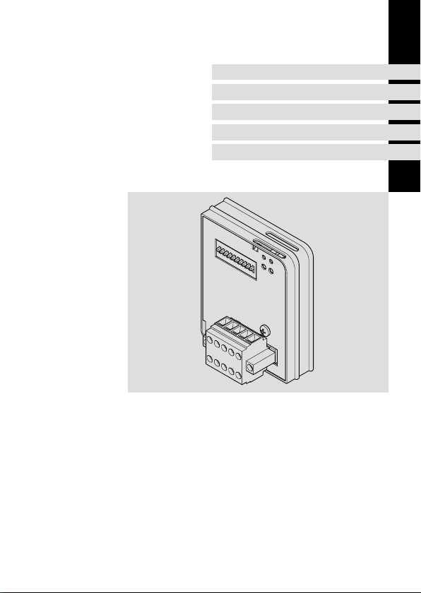
EMF2179IB
Kommunikationsmodul
Communication module
Module de communication
l
Page 2

, Lesen Sie zuerst diese Anleitung und die Dokumentation zum Grundgerät,
bevor Sie mit den Arbeiten beginnen!
Beachten Sie die enthaltenen Sicherheitshinweise.
, Please read these instructions and the documentation of the standard
device before you start working!
Observe the safety instructions given therein!
, Lire le présent fascicule et la documentation relative à l’appareil de base
avant toute manipulation de l’équipement !
Respecter les consignes de sécurité fournies.
Page 3
2179DEN001B
Page 4

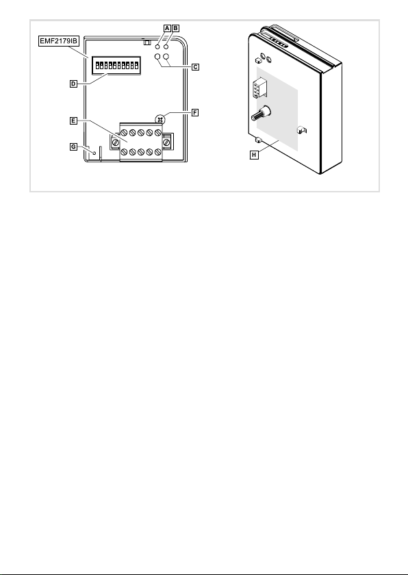
Legende zur Abbildung auf der Ausklappseite
Pos. Beschreibung Ausführliche
Verbindungsstatus zum Antriebsregler (zweifarbige LED)
0
Verbindungsstatus zum Bus (zweifarbige LED)
1
Drive (grüne und rote Drive−LED)
2
DIP−Schalter zur Einstellung der ...
3
l Geräteadresse (Schalter 1 ... 6)
l Übertragungsrate (Schalter 7 ... 8)
l Software−Kompatibilität zum Kommunikationsmodul EMF2175IB (Schal-
ter 10)
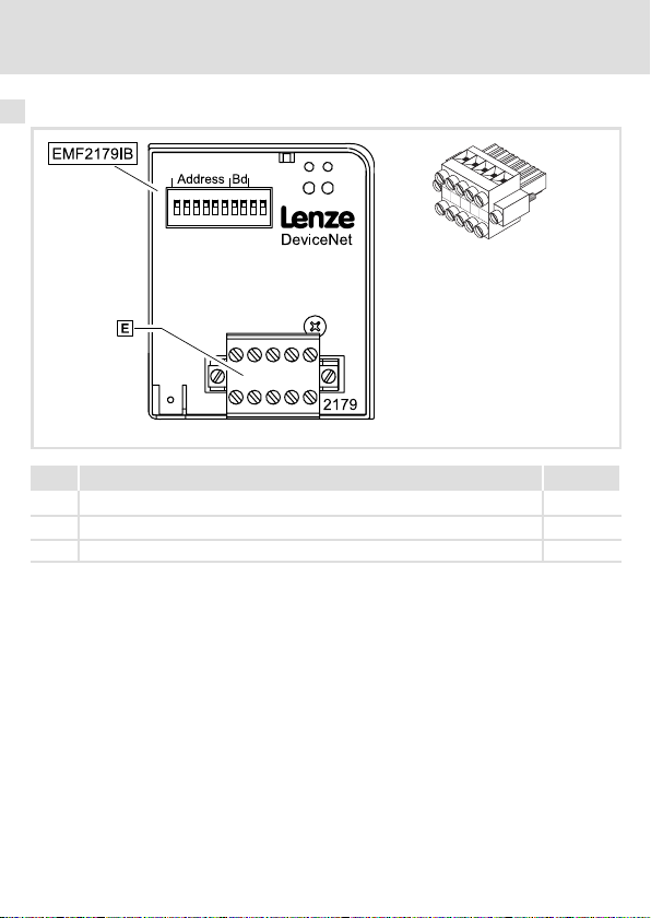
Steckerleiste mit Doppel−Schraubanschluss, 5−polig
4
Befestigungsschraube
5
Anschluss PE−Schirmkabel
6
Typenschild
7
0Abb. 0Tab. 0
Information
^ 39
^ 30
^ 20
^ 13
4
l
EDKMF2179 DE/EN/FR 4.0
Page 5

Inhalt i
1 Über diese Dokumentation 6 . . . . . . . . . . . . . . . . . . . . . . . . . . . . . . . . . . . . . . . . . .
Verwendete Konventionen 7 . . . . . . . . . . . . . . . . . . . . . . . . . . . . . . . . . . . . . . . . . .
Verwendete Hinweise 8 . . . . . . . . . . . . . . . . . . . . . . . . . . . . . . . . . . . . . . . . . . . . . . .
2 Sicherheitshinweise 10 . . . . . . . . . . . . . . . . . . . . . . . . . . . . . . . . . . . . . . . . . . . . . . . .
3 Produktbeschreibung 11 . . . . . . . . . . . . . . . . . . . . . . . . . . . . . . . . . . . . . . . . . . . . . . .
Bestimmungsgemäße Verwendung 11 . . . . . . . . . . . . . . . . . . . . . . . . . . . . . . . . . . .
Lieferumfang 12 . . . . . . . . . . . . . . . . . . . . . . . . . . . . . . . . . . . . . . . . . . . . . . . . . . . . . .
Identifikation 13 . . . . . . . . . . . . . . . . . . . . . . . . . . . . . . . . . . . . . . . . . . . . . . . . . . . . . .
4 Technische Daten 14 . . . . . . . . . . . . . . . . . . . . . . . . . . . . . . . . . . . . . . . . . . . . . . . . . .
Allgemeine Daten und Einsatzbedingungen 14 . . . . . . . . . . . . . . . . . . . . . . . . . . .
Schutzisolierung 15 . . . . . . . . . . . . . . . . . . . . . . . . . . . . . . . . . . . . . . . . . . . . . . . . . . .
Abmessungen 16 . . . . . . . . . . . . . . . . . . . . . . . . . . . . . . . . . . . . . . . . . . . . . . . . . . . . .
5 Mechanische Installation 17 . . . . . . . . . . . . . . . . . . . . . . . . . . . . . . . . . . . . . . . . . . . .
6 Elektrische Installation 18 . . . . . . . . . . . . . . . . . . . . . . . . . . . . . . . . . . . . . . . . . . . . . .
EMV−gerechte Verdrahtung 18 . . . . . . . . . . . . . . . . . . . . . . . . . . . . . . . . . . . . . . . . . .
Verdrahtung mit einem Leitrechner 19 . . . . . . . . . . . . . . . . . . . . . . . . . . . . . . . . . . .
Belegung der Steckerleiste 20 . . . . . . . . . . . . . . . . . . . . . . . . . . . . . . . . . . . . . . . . . . .
Daten der Anschlussklemmen 21 . . . . . . . . . . . . . . . . . . . . . . . . . . . . . . . . . . . . . . . .
Kabelspezifikation 22 . . . . . . . . . . . . . . . . . . . . . . . . . . . . . . . . . . . . . . . . . . . . . . . . .
Busleitungslänge 26 . . . . . . . . . . . . . . . . . . . . . . . . . . . . . . . . . . . . . . . . . . . . . . . . . .
Spannungsversorgung 27 . . . . . . . . . . . . . . . . . . . . . . . . . . . . . . . . . . . . . . . . . . . . .
7 Inbetriebnahme 29 . . . . . . . . . . . . . . . . . . . . . . . . . . . . . . . . . . . . . . . . . . . . . . . . . . .
Einstellmöglichkeiten durch DIP−Schalter 29 . . . . . . . . . . . . . . . . . . . . . . . . . . . . . .
Vor dem ersten Einschalten 33 . . . . . . . . . . . . . . . . . . . . . . . . . . . . . . . . . . . . . . . . . .
Erstes Einschalten 34 . . . . . . . . . . . . . . . . . . . . . . . . . . . . . . . . . . . . . . . . . . . . . . . . . .
Grundgerät über das Kommunikationsmodul freigeben 35 . . . . . . . . . . . . . . . . . .
8 Diagnose 39 . . . . . . . . . . . . . . . . . . . . . . . . . . . . . . . . . . . . . . . . . . . . . . . . . . . . . . . . .
LED−Statusanzeigen 39 . . . . . . . . . . . . . . . . . . . . . . . . . . . . . . . . . . . . . . . . . . . . . . .
EDKMF2179 DE/EN/FR 4.0
l
5
Page 6

1 Über diese Dokumentation
1 Über diese Dokumentation
Inhalt
Diese Dokumentation enthält ...
ƒ Sicherheitshinweise, die Sie unbedingt beachten müssen;
ƒ Informationen zur mechanischen und elektrischen Installation des
Kommunikationsmoduls;
ƒ Informationen zur Inbetriebnahme des Kommunikationsmoduls;
ƒ Angaben über Versionsstände der zu verwendenden Lenze Grundgeräte;
ƒ Technische Daten.
I Tipp!
Weiterführende Informationen zu diesem Kommunikationsmodul finden Sie
im entsprechenden Kommunikationshandbuch.
Die PDF−Datei finden Sie im Internet im Bereich "Services & Downloads" unter
http://www.Lenze.com
Zielgruppe
Diese Dokumentation wendet sich an Personen, die das beschriebene Produkt nach Projektvorgabe installieren und in Betrieb nehmen.
Informationen zur Gültigkeit
Die Informationen in dieser Dokumentation sind gültig für folgende Geräte:
ƒ Kommunikationsmodule EMF2179IB (DeviceNet) ab Version 1A.20.
I Tipp!
Dokumentationen und Software−Updates zu weiteren Lenze Produkten finden
Sie im Internet im Bereich "Services & Downloads" unter
http://www.Lenze.com
6
l
EDKMF2179 DE/EN/FR 4.0
Page 7

Über diese Dokumentation
Verwendete Konventionen
Verwendete Konventionen
Diese Dokumentation verwendet folgende Konventionen zur Unterscheidung verschiedener Arten von Information:
Informationsart Auszeichnung Beispiele/Hinweise
Zahlenschreibweise
Dezimaltrennzeichen Punkt Es wird generell der Dezimalpunkt
Symbole
Seitenverweis
^
verwendet.
Beispiel: 1234.56
Verweis auf eine andere Seite mit zusätzlichen Informationen
Beispiel: ^ 16 = siehe Seite 16
1
EDKMF2179 DE/EN/FR 4.0
l
7
Page 8

1 Über diese Dokumentation
Verwendete Hinweise
Verwendete Hinweise
Um auf Gefahren und wichtige Informationen hinzuweisen, werden in dieser Dokumentation folgende Piktogramme und Signalwörter verwendet:
Sicherheitshinweise
Aufbau der Sicherheitshinweise:
} Gefahr!
(kennzeichnet die Art und die Schwere der Gefahr)
Hinweistext
(beschreibt die Gefahr und gibt Hinweise, wie sie vermieden werden kann)
Piktogramm und Signalwort Bedeutung
Gefahr von Personenschäden durch gefährliche elektrische Spannung
{ Gefahr!
} Gefahr!
( Stop!
Hinweis auf eine unmittelbar drohende Gefahr, die den
Tod oder schwere Verletzungen zur Folge haben kann,
wenn nicht die entsprechenden Maßnahmen getroffen
werden.
Gefahr von Personenschäden durch eine allgemeine Gefahrenquelle
Hinweis auf eine unmittelbar drohende Gefahr, die den
Tod oder schwere Verletzungen zur Folge haben kann,
wenn nicht die entsprechenden Maßnahmen getroffen
werden.
Gefahr von Sachschäden
Hinweis auf eine mögliche Gefahr, die Sachschäden zur
Folge haben kann, wenn nicht die entsprechenden Maßnahmen getroffen werden.
8
l
EDKMF2179 DE/EN/FR 4.0
Page 9

Anwendungshinweise
Piktogramm und Signalwort Bedeutung
Über diese Dokumentation
Verwendete Hinweise
1
) Hinweis!
I Tipp!
,
Wichtiger Hinweis für die störungsfreie Funktion
Nützlicher Tipp für die einfache Handhabung
Verweis auf andere Dokumentation
EDKMF2179 DE/EN/FR 4.0
l
9
Page 10

2 Sicherheitshinweise
2 Sicherheitshinweise
} Gefahr!
Unsachgemäßer Umgang mit dem Kommunikationsmodul und dem
Grundgerät kann schwere Personenschäden und Sachschäden verursachen.
Beachten Sie die in der Dokumentation zum Grundgerät enthaltenen
Sicherheitshinweise und Restgefahren.
( Stop!
Elektrostatische Entladung
Durch elektrostatische Entladung können elektronische Bauteile innerhalb des
Kommunikationsmoduls beschädigt oder zerstört werden.
Mögliche Folgen:
ƒ Das Kommunikationsmodul ist defekt.
ƒ Die Feldbus−Kommunikation ist nicht möglich oder fehlerhaft.
Schutzmaßnahmen
ƒ Befreien Sie sich vor dem Berühren des Moduls von elektrostatischen
Aufladungen.
10
l
EDKMF2179 DE/EN/FR 4.0
Page 11

Produktbeschreibung
Bestimmungsgemäße Verwendung
3 Produktbeschreibung
Bestimmungsgemäße Verwendung
Das Kommunikationsmodul ...
ƒ ermöglicht die Kommunikation mit Lenze Antriebsreglern über den Feldbus
DeviceNet.
ƒ ist ein Betriebsmittel zum Einsatz in industriellen Starkstromanlagen.
ƒ ist eine Zubehör−Baugruppe, die mit folgenden Lenze Antriebsreglern eingesetzt
werden kann:
Gerätetyp Ausführung
82EVxxxxxBxxxXX Vx 1x 8200 vector
82CVxxxxxBxxxXX Vx 1x 8200 vector, Cold plate
82DVxxxKxBxxxXX Vx 1x 8200 vector, thermisch sepa-
EPL 10200 E 1x 8x Drive PLC
33.93XX xE. 2x 1x Vxxx 9321 ... 9332
33.938X xE. 1x 0x 9381 ... 9383
33.93XX xC. 2x 1x Vxxx 9321 ... 9332, Cold plate
33.93XX EI / ET 2x 8x Vxxx 9300 Servo PLC
33.93XX CI / CT 2x 8x Vxxx 9300 Servo PLC, Cold plate
ECSxSxxxx4xxxxXX
ECSxPxxxx4xxxxXX
ECSxMxxxx4xxxxXX
ECSxAxxxx4xxxxXX
1)
1)
1)
1)
Version
HW SW
1A 6.0 ECSxS (Speed and Torque)
1A 6.0 ECSxP (Posi and Shaft)
1A 6.0 ECSxM (Motion)
1A 2.3 ECSxA (Application)
Jede andere Verwendung gilt als sachwidrig!
Variante Erläuterung
riert
3
EDKMF2179 DE/EN/FR 4.0
l
11
Page 12
3 Produktbeschreibung
Lieferumfang
Lieferumfang
4
V-
C
A
N
S
_
L
H
C
L
A
D
N
_
H
V
+
2179DeN001B, E82ZAFX024
Pos. Lieferumfang Siehe
Kommunikationsmodul EMF2179IB (DeviceNet)
Montageanleitung
Steckerleiste mit Doppel−Schraubanschluss, 5−polig
4
12
l
^ 20
EDKMF2179 DE/EN/FR 4.0
Page 13
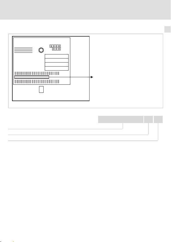
Identifikation
L
Type
Id.-No.
Prod.-No.
Ser.-No.
Produktbeschreibung
Identifikation
3
E82AF000P0B201XX
Gerätereihe
Hardwarestand
Softwarestand
EDKMF2179 DE/EN/FR 4.0
W
l
99371BC013
33.2179IB 1A 20
13
Page 14

4 Technische Daten
Allgemeine Daten und Einsatzbedingungen
4 Technische Daten
Allgemeine Daten und Einsatzbedingungen
Kommunikationsrelevante
Daten
Kommunikationsmedien DIN ISO 11898
Netzwerk−Topologie
Knotenadressen Max. 63
Leitungslänge Max. 500 m (abhängig von der Übertragungsrate)
Kommunikations−Profil DeviceNet
Allgemeine elektrische Daten Werte
Spannungsversorgung
(intern / extern)
Einsatzbedingungen Werte Abweichungen von der Norm
Klimatische Bedingungen
Schutzart IP20
Verschmutzungsgrad 2 nach IEC/EN 61800−5−1
Lagerung 1 K3 nach IEC/EN 60721−3−1 −25 °C ... + 60 °C
Transport 2 K3 nach IEC/EN 60721−3−2
Werte
Beidseitig abgeschlossene Linie (R = 120 )
Siehe ^ 28
Betrieb 3 K3 nach IEC/EN 60721−3−3 0 °C ... + 55 °C
14
l
EDKMF2179 DE/EN/FR 4.0
Page 15

Technische Daten
Schutzisolierung
Schutzisolierung
Schutzisolierung zwischen Bus und ... Art der Isolierung (nach EN 61800−5−1)
l Bezugserde / PE
l externer Versorgung (Kl. 39/59)
l Leistungsteil
– 820X / 821X Basisisolierung
– 822X / 8200 vector verstärkte Isolierung
– 93XX / 9300 Servo PLC verstärkte Isolierung
– ECSxS/P/M/A verstärkte Isolierung
l Steuerklemmen
– 820X / 821X / 8200 vector Betriebsisolierung
– 822X Basisisolierung
– 93XX / 9300 Servo PLC Basisisolierung
– ECSxS/P/M/A verstärkte Isolierung
Betriebsisolierung
Betriebsisolierung
4
EDKMF2179 DE/EN/FR 4.0
l
15
Page 16
4 Technische Daten
Abmessungen
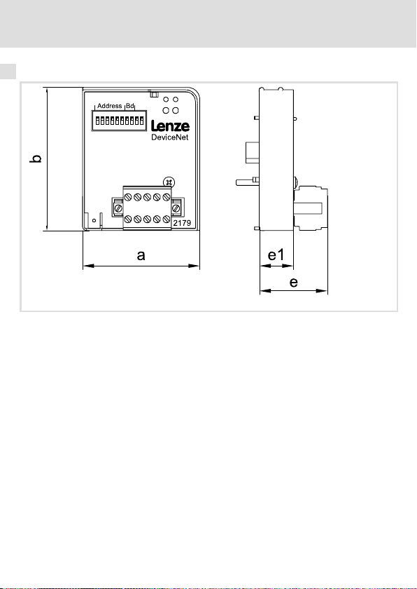
Abmessungen
a 62 mm
b 75 mm
e 36 mm
e1 18 mm
16
l
EDKMF2179 DE/EN/FR 4.0
Page 17
Mechanische Installation 5
5 Mechanische Installation
2102LEC014
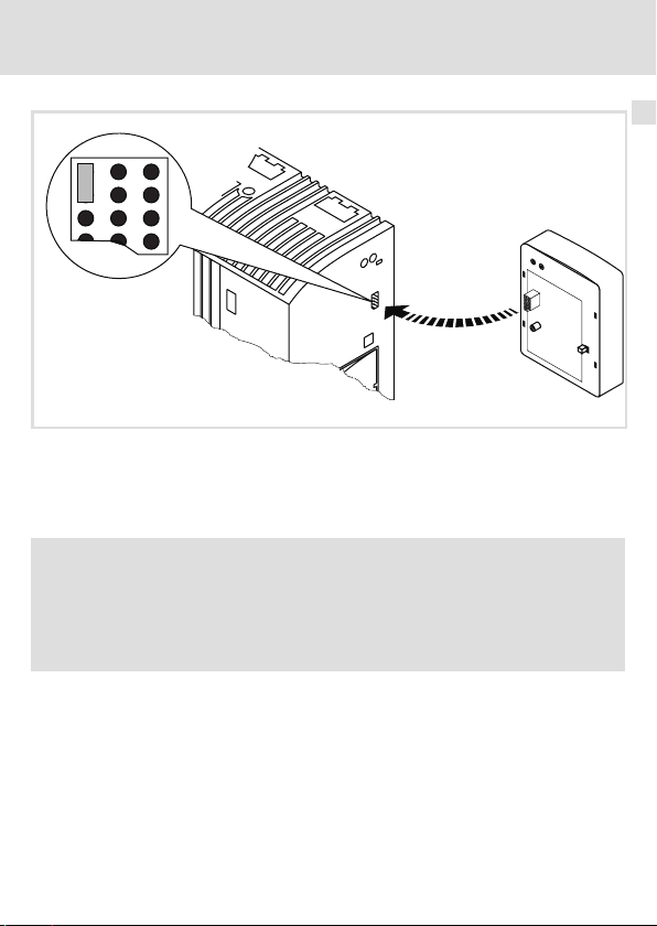
Abb. 1 Kommunikationsmodul aufstecken
ƒ Stecken Sie das Kommunikationsmodul auf das Grundgerät (hier: 8200 vector).
ƒ Schrauben Sie das Kommunikationsmodul mit der Befestigungsschraube auf dem
Grundgerät fest, um eine gute PE−Verbindung sicher zu stellen.
) Hinweis!
Zur internen Versorgung des Kommunikationsmoduls durch den
Frequenzumrichter 8200 vector muss der Jumper in der Schnittstellenöffnung
(siehe Abb. oben) angepasst werden.
Beachten Sie die Hinweise (^ 27).
EDKMF2179 DE/EN/FR 4.0
l
17
Page 18

6 Elektrische Installation
EMV−gerechte Verdrahtung
6 Elektrische Installation
EMV−gerechte Verdrahtung
Für eine EMV−gerechte Verdrahtung beachten Sie folgende Punkte:
) Hinweis!
ƒ Steuer−/Datenleitungen getrennt von Motorleitungen verlegen.
ƒ Legen Sie die Schirme der Steuer−/Datenleitungen bei digitalen Signalen
beidseitig auf.
ƒ Zur Vermeidung von Potenzialdifferenzen zwischen den
Kommunikationsteilnehmern eine Ausgleichsleitung mit einem
Querschnitt von mindestens 16mm2 einsetzen (Bezug:PE).
ƒ Beachten Sie die weiteren Hinweise zur EMV−gerechten Verdrahtung in der
Dokumentation des Grundgerätes.
Vorgehensweise bei der Verdrahtung
1. Bustopologie einhalten, deshalb keine Stichleitungen verwenden.
2. Hinweise und Verdrahtungsvorschriften in den Unterlagen zum Steuerungssystem
beachten.
3. Nur Kabel verwenden, die den aufgeführten Spezifikationen entsprechen (^ 22).
4. Zulässige Busleitungslänge einhalten (^ 26)
5. Busabschlusswiderstände von je 120 (Lieferumfang) anschließen:
– nur am physikalisch ersten und letzten Busteilnehmer
– zwischen den Klemmen CAN_L und CAN_H
.
18
l
EDKMF2179 DE/EN/FR 4.0
Page 19

Elektrische Installation
Verdrahtung mit einem Leitrechner
Verdrahtung mit einem Leitrechner
{ Gefahr!
Sie müssen eine zusätzliche Potenzialtrennung installieren, wenn ...
ƒ ein Antriebsregler 820X und 821X mit einem Leitrechner verbunden wird
und
ƒ eine sichere Potenzialtrennung (verstärkte Isolierung) nach EN 61800−5−1
notwendig ist.
Hierzu kann z. B. eine Anschaltbaugruppe für den Leitrechner mit einer zusätzlichen Potenzialtrennung verwendet werden (siehe jeweilige Herstellerangaben).
Berücksichtigen Sie bei der Verdrahtung die Potenzialtrennung der Versorgungsspannung.
Die Versorgungsspannung liegt auf demselben Potenzial wie der Datenbus.
Eine DeviceNet−Linie kann aus maximal 63 Teilnehmern bestehen. Zu den Teilnehmern zählen ...
ƒ der DeviceNet−Master (Scanner)
ƒ die angeschlossenen Lenze Grundgeräte
ƒ alle weiteren an der Kommunikation beteiligten Komponenten.
Verwenden Sie zur Einbindung der DeviceNet−Kommunikationsmodule einen PC mit installierter Software (z. B. »RSNetWorx«).
) Hinweis!
ƒ Legen Sie den Schirm an der Spannungsversorgung einmalig zusammen
mit dem Anschluss "V−" auf GND. Wählen Sie dazu möglichst den
Mittelpunkt der DeviceNet−Linie.
ƒ Für jeden Teilnehmer muss der Schirm des DeviceNet−Kabels ausschließlich
am Anschluss "Shield" der Steckerleiste aufgelegt werden.
ƒ Schließen Sie am ersten und letzten Teilnehmer der DeviceNet−Linie einen
Busabschluss−Widerstand von je 120
an.
6
EDKMF2179 DE/EN/FR 4.0
l
19
Page 20
6 Elektrische Installation
Belegung der Steckerleiste
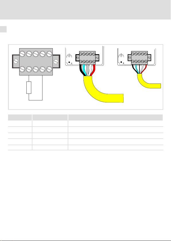
Belegung der Steckerleiste
Der Busanschluss des Kommunikationsmoduls erfolgt über die 5−polige Steckerleiste mit
Doppel−Schraubanschluss.
CAN_H
CAN_L
SHLD
V-
V+
120R
Thick
Klemme Kabelfarbe Beschreibung
V− schwarz Bezug für externe Spannungsversorgung
CAN_L blau
SHLD Schirmung
CAN_H weiß
V+ rot Externe Spannungsversorgung (^ 28)
20
Datenleitung / Eingang für Abschlusswiderstand 120
Datenleitung / Eingang für Abschlusswiderstand 120
l
Thin
EDKMF2179 DE/EN/FR 4.0
Page 21
Elektrische Installation
Daten der Anschlussklemmen
Daten der Anschlussklemmen
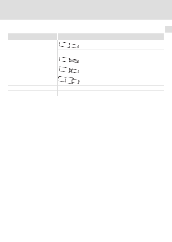
Elektrischer Anschluss Steckerleiste mit Doppel−Schraubanschluss
Anschlussmöglichkeiten
Anzugsmoment 0.5 ... 0.6 Nm (4.4 ... 5.3 lb−in)
Abisolierlänge 6 mm
starr: 1.5 mm
flexibel:
ohne Aderendhülse
1.5 mm
mit Aderendhülse, ohne Kunststoffhülse
1.5 mm
mit Aderendhülse, mit Kunststoffhülse
1.5 mm
2
(AWG 16)
2
(AWG 16)
2
(AWG 16)
2
(AWG 16)
6
EDKMF2179 DE/EN/FR 4.0
l
21
Page 22

6 Elektrische Installation
Kabelspezifikation
Kabelspezifikation
Die Teilnehmer am Bussystem müssen mit einer der DeviceNet−Spezifikation (DeviceNet
Adaption of CIP, Edition 1.1, Volume Three) entsprechenden Feldbusleitung ˘ einem DeviceNet Thick− oder Thin−Kabel ˘ miteinander verdrahtet werden.
Hersteller von DeviceNet Thick− und Thin−Kabel sind z. B. Belden Inc., Lapp Group, C&M
Corp. und Madison Cable Corp.
Eigenschaften des "Thick Cable" gemäß DeviceNet−Spezifikation
Allgemeine Eigenschaften
Anordnung Zwei abgeschirmte symmetrische Leitungen, gemeinsame Achse mit
Gesamtschirmung 65 % Abdeckung
Erdungsdraht Kupfer 18 mind.; mind. 19 Adern (einzeln verzinnt)
Außendurchmesser 10.41 ... 12.45 mm
Rundheit Die Radiusabweichung muss innerhalb 15 % des halben Außendurch-
Mantel beschriftung Verkäufername, Teilenr. und zusätzliche Beschriftung
Spez. DC−Widerstand (Umflechtung, Umwicklung, Ableitung)
Zertifizierungen (U.S. und Canada) NEC (UL), CL2/CL3 (min.)
Biegeradius 20 x Durchmesser (Installation) / 7 x Durchmesser (fest)
Umgebungstemperatur (Betrieb) −20 ... +60 °C bei 8 Ampere;
Lagertemperatur −40 ... +85 °C
Zugspannung 845.5 N
Erdungsdraht in der Mitte
AWG 36 (mind. 0.12 mm) verzinntes Kupfergeflecht (einzeln verzinnt)
messers liegen.
5.74 /km (nom. bis 20 °C)
lineare Stromreduzierung auf Null bei 80 °C
max
22
l
EDKMF2179 DE/EN/FR 4.0
Page 23

Elektrische Installation
Kabelspezifikation
Eigenschaften der Datenleitung
Leiterpaar Kupfer 18 mind.; mind. 19 Adern (einzeln verzinnt)
Isolationsdurchmesser 3.81 mm (nom.)
Farben Hellblau, weiss
Paarwindungen/m ca. 10
Abschirmung/Leiterpaar 2000/1000, Al/Mylar, Al−Seite außen, Falz zum Kurzschließen (bei
Impedanz
Kapazität zwischen Leitern 39.37 pF/m bei 1 kHz (nom.)
Kapazität zwischen einem Leiter und einem anderen, der mit dem Schirm verbunden ist.
Kapazitive Unsymmetrie 3937 pF/km bei 1 kHz (nom.)
Spez. DC−Widerstand bei 20 °C
Dämpfung 0.43 dB/100 m bei 125 kHz (max.)
Eigenschaften der Spannungsleitung
Leiterpaar Kupfer 15 mind.; mind. 19 Adern (einzeln verzinnt)
Isolationsdurchmesser 2.49 mm (nom.)
Farben Rot / schwarz
Paarwindungen/m ca. 10
Abschirmung/Leiterpaar 1000/1000, Al/Mylar, Al−Seite außen, mit Falz zum Kurzschließen (bei
Spez. DC−Widerstand bei 20 °C
Zugbelastung)
120 +/− 10 % bei 1 MHz
78.74 pF/m bei 1 kHz (nom.)
22.64 /km (max.)
0.82 dB/100 m bei 500 kHz (max.)
1.31 dB/100 m bei 1.00 MHz (max.)
Zugbelastung)
11.81 /km (max.)
6
EDKMF2179 DE/EN/FR 4.0
l
23
Page 24

6 Elektrische Installation
Kabelspezifikation
Eigenschaften des "Thin Cable" gemäß DeviceNet−Spezifikation
Allgemeine Eigenschaften
Anordnung Zwei abgeschirmte symmetrische Leitungen, gemeinsame Achse mit
Gesamtschirmung 65 % Abdeckung
Erdungsdraht Kupfer 22 mind.; mind. 19 Adern (einzeln verzinnt)
Außendurchmesser 6.096 ... 7.112 mm
Rundheit Die Radiusabweichung muss innerhalb 20 % des halben Außendurch-
Mantelbeschriftung Verkäufername, Teilenr. und zusätzliche Beschriftung
Spez. DC−Widerstand (Umflechtung, Umwicklung, Ableitung)
Zertifizierungen (U.S. und Canada) NEC (UL), CL2 (min.)
Biegeradius 20 x Durchmesser (Installation) / 7 x Durchmesser (fest)
Umgebungstemperatur (Betrieb) −20 ... +70 °C bei 1.5 Ampere;
Lagertemperatur −40 ... +85°C
Zugspannung 289.23 N
Eigenschaften der Datenleitung
Isolationsdurchmesser 1.96 mm (nom.)
Leiterpaar Kupfer 24 mind.; mind. 19 Adern (einzeln verzinnt)
Farben Hellblau, weiss
Paarwindungen/m ca. 16
Abschirmung/Leiterpaar 1000/1000, Al/Mylar, Al−Seite außen, mit Falz zum Kurzschließen (bei
Impedanz
Laufzeit 4.46 ns/m (max.)
Kapazität zwischen Leitern 39.37 pF/m bei 1 kHz (nom.)
Kapazität zwischen einem Leiter und einem anderen, der mit dem Schirm verbunden ist
Kapazitive Unsymmetrie 3.94 pF/km bei 1 kHz (max.)
Spez. DC−Widerstand bei 20 °C
Dämpfung 0.95 dB/100 m bei 125 kHz (max.)
Erdungsdraht in der Mitte
AWG 36 (mind. 0.12 mm) verzinntes Kupfergeflecht (einzeln verzinnt)
messers liegen.
10.5 /km (nom. bei 20 °C)
lineare Stromreduzierung auf Null bei 80 °C
max
Zugbelastung)
120 +/− 10 % bei 1 MHz
78.74 pF/m bei 1 kHz (nom.)
91.86 /km (max.)
1.64 dB/100 m bei 500 kHz (max.)
2.30 dB/100 m bei 1.00 MHz (max.)
24
l
EDKMF2179 DE/EN/FR 4.0
Page 25

Elektrische Installation
Kabelspezifikation
Eigenschaften der Spannungsleitung
Leiterpaar Kupfer 22 mind.; mind. 19 Adern (einzeln verzinnt)
Isolationsdurchmesser 1.4 mm (nominal)
Farben Rot, schwarz
Paarwindungen/m ca. 16
Abschirmung/Leiterpaar 1000/1000, Al/Mylar, Al−seite außen, mit Falz zum Kurzschließen (bei
Spez. DC−Widerstand bei 20 °C
Zugbelastung)
57.41 /km (max.)
6
EDKMF2179 DE/EN/FR 4.0
l
25
Page 26

6 Elektrische Installation
Busleitungslänge
Busleitungslänge
In Abhängigkeit der Übertragungsrate und des verwendeten Kabelstyps (Thick−Kabel /
Thin−Kabel) sind folgende Busleitungslängen möglich:
Übertragungsrate [kBit/s]
Thick−Kabel Thin−Kabel
125 500
250 250
500
Bei gemischter Verwendung der Kabeltypen "Thick" und "Thin" können Sie die maximalen
Kabellängen in Abhängigkeit der Übertragungsraten wie folgt bestimmen:
Übertragungsrate [kBit/s] Max. Busleitungslänge
125 500 m = L
250 250 m = L
500 100 m = L
L
: Länge des Thick−Kabels
thick
L
: Länge des Thin−Kabels
thin
100
thick
thick
thick
+ 5 L
+ 2,5 L
+ L
thin
thin
thin
Busleitungslänge [m]
100
) Hinweis!
Die von Datenmenge, Zykluszeit und Teilnehmeranzahl abhängige
Übertragungsrate nur so hoch wählen, wie es für die Anwendung erforderlich
ist.
26
l
EDKMF2179 DE/EN/FR 4.0
Page 27
Elektrische Installation
Spannungsversorgung
Spannungsversorgung
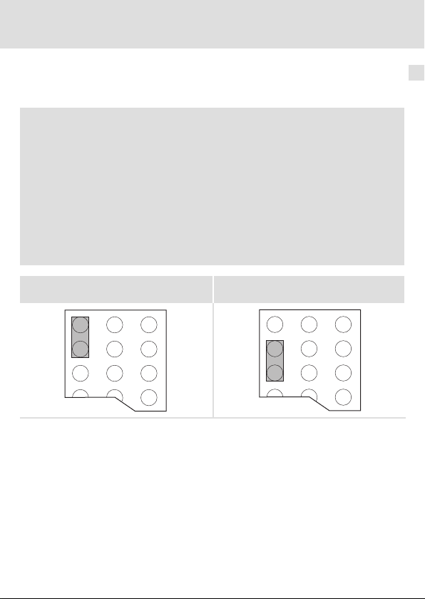
Interne DC−Spannungsversorgung
) Hinweis!
Die Vorgabe der internen Spannungsversorgung ist bei Grundgeräten mit
erweiterter AIF−Schnittstellenöffnung (z. B. Frontseite 8200 vector) gegeben.
Die in der Grafik grau hervorgehobene Fläche kennzeichnet die
Jumper−Position.
ƒ Im Auslieferungszustand des Grundgerätes werden diese nicht intern
versorgt.
ƒ Zur internen Spannungsversorgung platzieren Sie den Jumper auf die
unten angegebene Position.
Bei allen anderen Gerätereihen (9300, ECS) ist eine Spannungsversorgung vom
Grundgerät immer vorhanden.
6
(Nur externe Spannungsversorgung möglich.)
EDKMF2179 DE/EN/FR 4.0
Auslieferungszustand
l
Interne Spannungsversorgung
27
Page 28

6 Elektrische Installation
Spannungsversorgung
Externe Spannungsversorgung
Setzen Sie beim Kommunikationsmodul EMF2179IB immer eine externe Spannungsversor-
gung ein.
Die externe Spannungsversorgung des Kommunikationsmoduls erfolgt über die Steckkon-
takte V+ und V−.
Bezeichnung Beschreibung
V+ Die externe Versorgung übertrifft die Vorgabe der DeviceNet−Spezifikation.
V− Bezugspotential für die externe Spannungsversorgung
Bei größeren Entfernungen zwischen den DeviceNet−Teilnehmern können mehrere Spannungsversorgungen verwendet werden.
Antriebsregler Externe Spannungsversorgung
820X Immer erforderlich
821X, 822X, 824X
93XX
ECSxS/P/M/A
8200 vector Siehe "Interne Spannungsversorgung" (^ 27).
U = 24 V DC (21.6 V − 0 % ... 26.4 V + 0 %)
I = 100 mA
Die externe Spannungsversorgung ist notwendig, wenn beim Ausfall der
Versorgung des Grundgerätes die Kommunikation bestehen bleiben soll.
28
l
EDKMF2179 DE/EN/FR 4.0
Page 29

Einstellmöglichkeiten durch DIP−Schalter
7 Inbetriebnahme
Einstellmöglichkeiten durch DIP−Schalter
Über die frontseitig angeordneten DIP−Schalter können eingestellt werden:
ƒ Teilnehmeradresse (Schalter 1 ... 6)
ƒ Übertragungsrate (Schalter 7, 8)
ƒ Software−Kompatibilität zum Kommunikationsmodul EMF2175IB (Schalter 10)
Der Schalter 9 hat keine Funktion.
Die Lenze−Einstellung aller DIP−Schalter ist OFF.
) Hinweis!
Schalten Sie die Spannungsversorgung des Kommunikationsmoduls aus und
anschließend wieder ein, um geänderte Einstellungen zu aktivieren.
Inbetriebnahme
7
EDKMF2179 DE/EN/FR 4.0
l
29
Page 30
7 Inbetriebnahme
Einstellmöglichkeiten durch DIP−Schalter
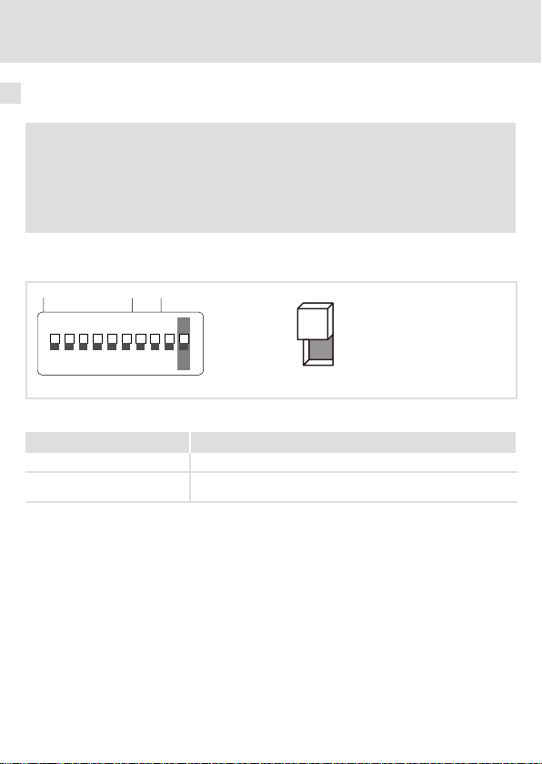
Software−Kompatibilität einstellen
) Hinweis!
Beachten Sie bei aktiver Kompatibilität (Schalter 10 = ON) die Informationen
in der Dokumentation zum Kommunikationsmodul EMF2175IB.
Dies gilt insbesondere für die mit dieser Einstellung geänderte Belegung der
DIP−Schalter.
Mit dem DIP−Schalter 10 aktivieren Sie die Software−Kompatibilität zum Kommunikationsmodul EMF2175IB.
Address Bd
OPEN
12 43 5678910
Abb. 2 Software−Kompatibilität einstellen
Schalterstellung Kompatibilität
OFF Keine Kompatibilität
ON Kompatibilität aktiv
OFF
ON
30
l
EDKMF2179 DE/EN/FR 4.0
Page 31

Einstellmöglichkeiten durch DIP−Schalter
Teilnehmeradresse einstellen
Address Bd
Inbetriebnahme
OPEN
12 43 5678910
Abb. 3 Adressierung über DIP−Schalter
ƒ Die Teilnehmeradressen bei mehreren vernetzten DeviceNet−Teilnehmern müssen
sich voneinander unterscheiden.
ƒ Alle in Stellung ON befindlichen Schalter (1 ... 6) ergeben in der Summe der
Wertigkeiten die gewünschte Knotenadresse.
DIP−Schalter Wertigkeit
Schalterstellung Teilnehmeradresse
132OFF
2 16 ON
3 8 OFF
4 4 ON
5 2 ON
6 1 ON
OFF
ON
Beispiel
16 + 4 + 2 + 1 = 23
7
EDKMF2179 DE/EN/FR 4.0
l
31
Page 32

7 Inbetriebnahme
Einstellmöglichkeiten durch DIP−Schalter
Übertragungsrate einstellen
Address Bd
OPEN
12 43 5678910
Abb. 4 Einstellen der Übertragungsrate
ƒ Die Übertragungsrate muss bei allen DeviceNet−Teilnehmern identisch eingestellt
werden.
ƒ Folgende Übertragungsraten können eingestellt werden:
Übertragungsrate [kBit/s]
125 OFF OFF
250 OFF ON
500 ON OFF
7 8
OFF
ON
Schalter
32
l
EDKMF2179 DE/EN/FR 4.0
Page 33

Inbetriebnahme
Vor dem ersten Einschalten
Vor dem ersten Einschalten
( Stop!
Bevor Sie das Grundgerät mit dem Kommunikationsmodul erstmalig
einschalten, überprüfen Sie
ƒ die gesamte Verdrahtung auf Vollständigkeit, Kurzschluss und Erdschluss.
ƒ ob das Bussystem beim physikalisch ersten und letzten Busteilnehmer
durch den Busabschlusswiderstand abgeschlossen ist.
7
EDKMF2179 DE/EN/FR 4.0
l
33
Page 34

7 Inbetriebnahme
Erstes Einschalten
Erstes Einschalten
) Hinweis!
Halten Sie die Inbetriebnahmeschritte in der vorgegebenen Reihenfolge ein.
1. Das Grundgerät und ggf. die externe Spannungsversorgung des
Kommunikationsmoduls einschalten.
– Die grüne LED 0 (Verbindungsstatus zum Grundgerät) auf der Frontseite des
Kommunikationsmoduls leuchtet.
– Die LED 1 (Verbindungsstatus zum Bus) auf der Frontseite des
Kommunikationsmoduls blinkt grün.
– Die grüne Status−LED des Grundgerätes (Drive−LED) 2 muss leuchten oder blinken.
Die Bedeutung der Signalisierung finden Sie in der Dokumentation des
Grundgerätes.
2. Das Kommunikationsmodul über die Konfigurationssoftware (z. B. »RSNetWorx«) in
das DeviceNet einbinden.
– Der Zustand der LED 1 (Verbindungsstatus zum Bus) wechselt von "Blinken" auf
"Leuchten", wenn das Kommunikationsmodul konfiguriert ist.
3. Sie können jetzt mit dem Antrieb kommunizieren, d. h.
– Sie können über "explicit messages" alle Parameter vom Antrieb und/oder
Kommunikationsmodullesen und schreiben.
– Sie können Istwerte (z. B. Statuswort) lesen oder Sollwerte (z. B. Frequenzsollwert)
schreiben.
34
l
EDKMF2179 DE/EN/FR 4.0
Page 35

Grundgerät über das Kommunikationsmodul freigeben
Grundgerät über das Kommunikationsmodul freigeben
) Hinweis!
ƒ Während des Betriebs kann das Umstecken des Kommunikationsmoduls
auf einen anderen Antriebsregler zu undefinierten Betriebszuständen
führen.
ƒ Lenze−Codestellen im Grundgerät und im Kommunikationsmodul können
über die herstellerspezifische Klasse "110" gelesen und geschrieben
werden.
ƒ Aktuelle Programmbeispiele finden Sie im Internet im Bereich ˜Services &
Downloads˜ unter
http://www.Lenze.com
Frequenzumrichter 82XX / 8200 vector
Schritt Vorgehensweise Bemerkungen
Inbetriebnahme
1. C0001 von
"0" auf "3" stellen
2. Klemme 28 auf
HIGH−Pegel legen
3. Eingangsklemme für
QSP auf HIGH−Pegel
legen
4. Der Antriebsregler nimmt nun Parameter− und Prozessdaten an.
Der Lenze−Parameter C0001 (Bedienungsart) kann mit dem Keypad XT oder direkt über DeviceNet eingestellt werden.
Beispiel zur Einstellung direkt über DeviceNet:
Write (C0001 = 3)
l Class: 0x6E (110
l Instanz: 0x1
l Attribut: 0x1
l Servicecode: Set Single Attribut
l Data send: 0x7530 (30000
Die Klemme 28 (Reglerfreigabe) ist immer aktiv und muss während
des DeviceNet−Betriebs auf HIGH−Pegel liegen. Andernfalls kann der
Antriebsregler über DeviceNet nicht freigegeben werden.
Die Funktion QSP (Schnellhalt) ist immer aktiv. Falls QSP auf eine
Eingangsklemme konfiguriert ist (Lenze−Einstellung: nicht belegt),
muss diese während des DeviceNet−Betriebs auf HIGH−Pegel liegen.
)
dez
)
dez
7
EDKMF2179 DE/EN/FR 4.0
l
35
Page 36

7 Inbetriebnahme
Grundgerät über das Kommunikationsmodul freigeben
Servo−Umrichter 93XX
Schritt Vorgehensweise Bemerkungen
1. C0005 auf den Wert
"xxx3" einstellen
2. C0142 = 0 einstellen Siehe "Schutz vor unkontrolliertem Wiederanlauf" (^ 38).
3. Klemme 28 auf
HIGH−Pegel legen
4. Klemme E1 auf
HIGH−Pegel legen
5. Klemme X5/A1 verbinden mit
l X5/28 und
l X5/E1
6. Der Antriebsregler nimmt nun Parameter− und Prozessdaten an.
Der Wert "xxx3" des Lenze−Parameters C0005 (Steuerung des Antriebsregler über DeviceNet) kann mit dem Keypad XT oder direkt
über DeviceNet eingestellt werden.
Beispiel für die erste Inbetriebnahme mit der Signalkonfiguration
"1013":
Write (C0005 = 1013)
l Class: 0x6E (110
l Instanz: 0x5
l Attribut: 1
l Servicecode: Set Single Attribute
l Data send: 0x9A9250 (10130000
Die Klemme 28 (Reglerfreigabe) ist immer aktiv und muss während
des DeviceNet−Betriebs auf HIGH−Pegel liegen. Andernfalls kann der
Antriebsregler über DeviceNet nicht freigegeben werden.
Bei der Signalkonfiguration C0005 = 1013 ist die Funktion QSP
(Schnellhalt) in Verbindung mit der Rechts−/Links−Umschaltung auf
die digitalen Eingangsklemmen E1 und E2 gelegt und somit immer
aktiv.
Betrifft nur die Signalkonfiguration C0005 = xx13
Bei dieser Signalkonfiguration ist die Klemme A1 als Spannungsausgang geschaltet.
)
dez
)
dez
36
l
EDKMF2179 DE/EN/FR 4.0
Page 37

Grundgerät über das Kommunikationsmodul freigeben
Inbetriebnahme
ECSXX über das Kommunikationsmodul freigeben
Schritt Vorgehensweise Bemerkungen
1. Steuerschnittstelle
"AIF" über Codestelle
wählen.
2. C0142 = 0 einstellen Siehe "Schutz vor unkontrolliertem Wiederanlauf" (^ 38).
3. Klemme X6/SI1 und
X6/SI2 auf HIGH−Pegel legen
4. Der Antriebsregler nimmt nun Parameter− und Prozessdaten an.
Siehe Dokumentation des entsprechenden ECS−Antriebsreglers.
Beispiel für die erste Inbetriebnahme mit der Signalkonfiguration
"1013":
Write (C0005 = 1013)
l Class: 0x6E (110
l Instanz: 0x5
l Attribut: 1
l Servicecode: Set Single Attribute
l Data send: 0x9A9250 (10130000
Die Klemmen X6/SI1 (Reglerfreigabe−/sperre) und X6/SI2 (Impulsfreigabe−/sperre) sind immer aktiv und müssen während des DeviceNet−Betriebs auf HIGH−Pegel liegen. Andernfalls kann der Antriebsregler über DeviceNet nicht freigegeben werden.
)
dez
)
dez
7
EDKMF2179 DE/EN/FR 4.0
l
37
Page 38

7 Inbetriebnahme
Grundgerät über das Kommunikationsmodul freigeben
Schutz vor unkontrolliertem Wiederanlauf
) Hinweis!
Aufbau der Kommunikation
Zum Aufbau der Kommunikation ist es beim extern versorgten
Kommunikationsmodul erforderlich, auch das Grundgerät anfangs
einzuschalten.
Die weitere Kommunikation des extern versorgten Moduls bleibt anschließend
unabhängig vom Einschaltzustand des Grundgerätes.
Schutz vor unkontrolliertem Wiederanlauf
Nach einer Störung (z. B. kurzzeitiger Netzausfall) ist der Wiederanlauf eines
Antriebs in manchen Fällen unerwünscht oder sogar unzulässig.
Über C0142 können Sie das Wiederanlaufverhalten des Antriebsreglers
einstellen:
ƒ C0142 = 0 (Lenze−Einstellung)
– Der Antriebsregler bleibt gesperrt (auch wenn die Störung nicht mehr
aktiv ist).
– Der Antrieb läuft kontrolliert an durch explizite Reglerfreigabe:
93XX: Klemme 28 auf HIGH−Pegel legen.
ECSXX: Klemmen X6/SI1 und X6/SI2 auf HIGH−Pegel legen.
ƒ C0142 = 1
– Ein unkontrollierter Anlauf des Antriebs ist möglich.
38
l
EDKMF2179 DE/EN/FR 4.0
Page 39

LED−Statusanzeigen
8 Diagnose
LED−Statusanzeigen
LED
Pos. Farbe Zustand
grün
0
1
2
blinkt Das Kommunikationsmodul ist mit Spannung versorgt, hat aber
an Das Kommunikationsmodul ist mit Spannung versorgt und hat
aus
grün blinkt Dup_Mac_ID−Test durchlaufen. Die Verbindung zum Master ist
grün an Die DeviceNet−Verbindung ist aufgebaut.
rot blinkt Keine Kommunikation wegen Zeitüberschreitung
rot an Interner Fehler des Kommunikationsmoduls
Betriebszustand des Grundgerätes (siehe Dokumentation zum Grundgerät)
Beschreibung
keine Verbindung zum Grundgerät. (Das Grundgerät ist ausgeschaltet, in der Initialisierungsphase oder nicht vorhanden.)
eine Verbindung zum Grundgerät.
l Keine Kommunikation mit dem Kommunikationsmodul
l Das Kommunikationsmodul wird nicht mit Spannung ver-
sorgt.
noch nicht aufgebaut.
Diagnose
2179DeN001B
8
EDKMF2179 DE/EN/FR 4.0
l
39
Page 40

Legend for fold−out page
Pos. Description Detailed
Connection status to the drive controller (two−coloured LED)
0
Connection status to the bus (two−coloured LED)
1
Drive (green and red drive LED)
2
DIP switches for setting the ...
3
l device address (switches 1 ... 6)
l baud rate (switches 7 ... 8)
l Software compatibility to the EMF2175IB communication module (switch
10)
Plug connector with double screw connection, 5−pole
4
Fixing screw
5
PE shield cable connection
6
Nameplate
7
0Fig. 0Tab. 0
information
^ 75
^ 66
^ 56
^ 49
40
l
EDKMF2179 DE/EN/FR 4.0
Page 41

Contents i
1 About this documentation 42 . . . . . . . . . . . . . . . . . . . . . . . . . . . . . . . . . . . . . . . . . . .
Conventions used 43 . . . . . . . . . . . . . . . . . . . . . . . . . . . . . . . . . . . . . . . . . . . . . . . . . .
Notes used 44 . . . . . . . . . . . . . . . . . . . . . . . . . . . . . . . . . . . . . . . . . . . . . . . . . . . . . . . .
2 Safety instructions 46 . . . . . . . . . . . . . . . . . . . . . . . . . . . . . . . . . . . . . . . . . . . . . . . . .
3 Product description 47 . . . . . . . . . . . . . . . . . . . . . . . . . . . . . . . . . . . . . . . . . . . . . . . . .
Application as directed 47 . . . . . . . . . . . . . . . . . . . . . . . . . . . . . . . . . . . . . . . . . . . . . .
Scope of supply 48 . . . . . . . . . . . . . . . . . . . . . . . . . . . . . . . . . . . . . . . . . . . . . . . . . . . .
Identification 49 . . . . . . . . . . . . . . . . . . . . . . . . . . . . . . . . . . . . . . . . . . . . . . . . . . . . . .
4 Technical data 50 . . . . . . . . . . . . . . . . . . . . . . . . . . . . . . . . . . . . . . . . . . . . . . . . . . . . .
General data and operating conditions 50 . . . . . . . . . . . . . . . . . . . . . . . . . . . . . . .
Protective insulation 51 . . . . . . . . . . . . . . . . . . . . . . . . . . . . . . . . . . . . . . . . . . . . . . . .
Dimensions 52 . . . . . . . . . . . . . . . . . . . . . . . . . . . . . . . . . . . . . . . . . . . . . . . . . . . . . . .
5 Mechanical installation 53 . . . . . . . . . . . . . . . . . . . . . . . . . . . . . . . . . . . . . . . . . . . . .
6 Electrical installation 54 . . . . . . . . . . . . . . . . . . . . . . . . . . . . . . . . . . . . . . . . . . . . . . .
Wiring according to EMC 54 . . . . . . . . . . . . . . . . . . . . . . . . . . . . . . . . . . . . . . . . . . . .
Wiring to a host 55 . . . . . . . . . . . . . . . . . . . . . . . . . . . . . . . . . . . . . . . . . . . . . . . . . . . .
Assignment of the plug connector 56 . . . . . . . . . . . . . . . . . . . . . . . . . . . . . . . . . . . . .
Connection terminals 57 . . . . . . . . . . . . . . . . . . . . . . . . . . . . . . . . . . . . . . . . . . . . . .
Cable specification 58 . . . . . . . . . . . . . . . . . . . . . . . . . . . . . . . . . . . . . . . . . . . . . . . . .
Bus cable length 62 . . . . . . . . . . . . . . . . . . . . . . . . . . . . . . . . . . . . . . . . . . . . . . . . . . .
Voltage supply 63 . . . . . . . . . . . . . . . . . . . . . . . . . . . . . . . . . . . . . . . . . . . . . . . . . . . .
7 Commissioning 65 . . . . . . . . . . . . . . . . . . . . . . . . . . . . . . . . . . . . . . . . . . . . . . . . . . . .
Possible settings via DIP switch 65 . . . . . . . . . . . . . . . . . . . . . . . . . . . . . . . . . . . . . .
Before switching on 69 . . . . . . . . . . . . . . . . . . . . . . . . . . . . . . . . . . . . . . . . . . . . . . . .
Initial switch−on 70 . . . . . . . . . . . . . . . . . . . . . . . . . . . . . . . . . . . . . . . . . . . . . . . . . . .
Enabling the standard device via the communication module 71 . . . . . . . . . . . . . .
8 Diagnostics 75 . . . . . . . . . . . . . . . . . . . . . . . . . . . . . . . . . . . . . . . . . . . . . . . . . . . . . . .
LED status displays 75 . . . . . . . . . . . . . . . . . . . . . . . . . . . . . . . . . . . . . . . . . . . . . . . .
EDKMF2179 DE/EN/FR 4.0
l
41
Page 42

1 About this documentation
1 About this documentation
Contents
This documentation provides ...
ƒ safety instructions that must be observed;
ƒ information about the mechanical and electrical installation of the communication
module;
ƒ information about the commissioning of the communication module;
ƒ information about the versions of the Lenze standard devices to be used;
ƒ technical data.
I Tip!
Further information about this communication module can be found in the
corresponding communication manual.
The pdf file can be found on the Internet in the "Services & Downloads" area
under
http://www.Lenze.com
Target group
This documentation is intended for persons who install and commission the described
product according to the project requirements.
Validity information
The information given in this documentation is valid for the following devices:
ƒ EMF2179IB communication modules (DeviceNet) from version 1A.20.
I Tip!
Documentation and software updates for further Lenze products can be found
on the Internet in the "Services & Downloads" area under
http://www.Lenze.com
42
l
EDKMF2179 DE/EN/FR 4.0
Page 43

About this documentation
Conventions used
Conventions used
This documentation uses the following conventions to distinguish between different types
of information:
Type of information Identification Examples/notes
Numbers
Decimal separator Point The decimal point is used throughout
Symbols
Page reference
^
this documentation.
Example: 1234.56
Reference to another page with
additional information
Example: ^ 16 = see page 16
1
EDKMF2179 DE/EN/FR 4.0
l
43
Page 44

1 About this documentation
Notes used
Notes used
The following pictographs and signal words are used in this documentation to indicate
dangers and important information:
Safety instructions
Structure of safety instructions:
} Danger!
(characterises the type and severity of danger)
Note
(describes the danger and gives information about how to prevent dangerous
situations)
Pictograph and signal word Meaning
Danger of personal injury through dangerous electrical
{ Danger!
} Danger!
( Stop!
voltage.
Reference to an imminent danger that may result in
death or serious personal injury if the corresponding
measures are not taken.
Danger of personal injury through a general source of
danger.
Reference to an imminent danger that may result in
death or serious personal injury if the corresponding
measures are not taken.
Danger of property damage.
Reference to a possible danger that may result in
property damage if the corresponding measures are not
taken.
44
l
EDKMF2179 DE/EN/FR 4.0
Page 45

Application notes
Pictograph and signal word Meaning
About this documentation
Notes used
1
) Note!
I Tip!
,
Important note to ensure troublefree operation
Useful tip for simple handling
Reference to another documentation
EDKMF2179 DE/EN/FR 4.0
l
45
Page 46

2 Safety instructions
2 Safety instructions
} Danger!
Inappropriate handling of the communication module and the standard device
can cause serious personal injury and material damage.
Observe the safety instructions and residual hazards described in the
documentation for the standard device.
( Stop!
Electrostatic discharge
Electronic components of the communication module can be damaged or
destroyed through electrostatic discharge.
Possible consequences:
ƒ The communication module is damaged.
ƒ Fieldbus communication is not possible or faulty.
Protective measures
ƒ Discharge electrostatic charges before touching the module.
46
l
EDKMF2179 DE/EN/FR 4.0
Page 47

Product description
Application as directed
3 Product description
Application as directed
The communication module ...
ƒ enables communication with Lenze controllers via the DeviceNet fieldbus.
ƒ is a device for the use in industrial power systems.
ƒ is an accessory module for use in conjunction with the following Lenze controllers:
Device type Design
82EVxxxxxBxxxXX Vx 1x 8200 vector
82CVxxxxxBxxxXX Vx 1x 8200 vector, cold plate
82DVxxxKxBxxxXX Vx 1x 8200 vector, thermally
EPL 10200 E 1x 8x Drive PLC
33.93XX xE. 2x 1x Vxxx 9321 ... 9332
33.938X xE. 1x 0x 9381 ... 9383
33.93XX xC. 2x 1x Vxxx 9321 ... 9332, cold plate
33.93XX EI / ET 2x 8x Vxxx 9300 servo PLC
33.93XX CI / CT 2x 8x Vxxx 9300 servo PLC, cold plate
ECSxSxxxx4xxxxXX
ECSxPxxxx4xxxxXX
ECSxMxxxx4xxxxXX
ECSxAxxxx4xxxxXX
1)
1)
1)
1)
Version
HW SW
1A 6.0 ECSxS (Speed and Torque)
1A 6.0 ECSxP (Posi and Shaft)
1A 6.0 ECSxM (Motion)
1A 2.3 ECSxA (Application)
Any other use shall be deemed inappropriate!
Variant Explanation
separated
3
EDKMF2179 DE/EN/FR 4.0
l
47
Page 48

3 Product description
Scope of supply
Scope of supply
4
V-
CAN_L
SHLD
CAN_H
V+
Pos. Scope of supply See
EMF2179IB communication module (DeviceNet)
Mounting instructions
Plug connector with double screw connection, 5−pole
4
48
l
2179DeN001B, E82ZAFX024
EDKMF2179 DE/EN/FR 4.0
^ 56
Page 49

Identification
L
Type
Id.-No.
Prod.-No.
Ser.-No.
Product description
Identification
3
E82AF000P0B201XX
Series
Hardware version
Software version
EDKMF2179 DE/EN/FR 4.0
W
l
99371BC013
33.2179IB 1A 20
49
Page 50

4 Technical data
General data and operating conditions
4 Technical data
General data and operating conditions
Communication−relevant data Values
Communication media DIN ISO 11898
Network topology
Number of nodes Max. 63
Cable length Max. 500 m (depending on the baud rate)
Communication profile DeviceNet
General electrical data Values
Voltage supply
(internal / external)
Operating conditions Values Deviations from standard
Climatic conditions
Transport 2 K3 to IEC/EN 60721−3−2
Operation 3 K3 to IEC/EN 60721−3−3 0 °C ... + 55 °C
Enclosure IP20
Degree of pollution 2 to IEC/EN 61800−5−1
Line terminated at both ends (R = 120 )
See ^ 64
Storage 1 K3 to IEC/EN 60721−3−1 −25 °C ... + 60 °C
50
l
EDKMF2179 DE/EN/FR 4.0
Page 51

Technical data
Protective insulation
Protective insulation
Protective insulation between bus and ... Type of insulation (in accordance with EN 61800−5−1)
l Reference earth / PE
l External supply (cl. 39/59)
l Power section
– 820X / 821X Basic insulation
– 822X / 8200 vector Reinforced insulation
– 93XX / 9300 servo PLC Reinforced insulation
– ECSxS/P/M/A Reinforced insulation
l Control terminals
– 820X / 821X / 8200 vector Functional insulation
– 822X Basic insulation
– 93XX / 9300 servo PLC Basic insulation
– ECSxS/P/M/A Reinforced insulation
Functional insulation
Functional insulation
4
EDKMF2179 DE/EN/FR 4.0
l
51
Page 52

4 Technical data
Dimensions
Dimensions
a 62 mm
b 75 mm
e 36 mm
e1 18 mm
52
l
EDKMF2179 DE/EN/FR 4.0
Page 53

Mechanical installation 5
5 Mechanical installation
2102LEC014
Fig. 1 Attaching the communication module
ƒ Plug the communication module onto the standard device (here: 8200 vector).
ƒ Tighten the communication module to the standard device using the fixing screw in
order to ensure a good PE connection.
) Note!
For the internal supply of the communication module by the 8200 vector
frequency inverter the jumper has to be adjusted within the interface opening
(see illustration above).
Observe the notes (^ 63).
EDKMF2179 DE/EN/FR 4.0
l
53
Page 54

6 Electrical installation
Wiring according to EMC
6 Electrical installation
Wiring according to EMC
For wiring according to EMC requirements observe the following points:
) Note!
ƒ Separate control cables/data lines from motor cables.
ƒ Connect the shields of control cables/data lines at both ends in the case of
digital signals.
ƒ Use an equalizing conductor with a cross−section of at least 16mm
(reference:PE) to avoid potential differences between the bus nodes.
ƒ Observe the other notes concerning EMC−compliant wiring given in the
documentation for the standard device.
Procedure for wiring
1. Observe the bus topology, i.e. do not use stubs.
2. Observe notes and wiring instructions in the documents for the control system.
3. Only use cables complying to the specifications listed (^ 58).
4. Observe the permissible bus cable length (^ 62)
5. Connect bus terminating resistors of 120 each (scope of supply):
– only to the physically first and last node
– between the terminals CAN_L and CAN_H
.
2
54
l
EDKMF2179 DE/EN/FR 4.0
Page 55

Electrical installation
Wiring to a host
Wiring to a host
{ Danger!
You have to provide additional electrical isolation if ...
ƒ an 820X and 821X controller is connected to the host and
ƒ a safe electrical isolation (reinforced insulation) according to EN 61800−5−1
is required.
For this purpose for instance an interface module for the master computer with an
additional electrical isolation can be used (see respective manufacturer information).
For wiring observe the electrical isolation of the supply voltage. The supply voltage is on the
same potential as the data bus.
A DeviceNet line can have max. 63 nodes. The nodes are ...
ƒ the DeviceNet master (scanner)
ƒ the connected Lenze standard devices
ƒ all other components which take part in the communication.
For integration of the DeviceNet communication modules use a PC with an installed
software (e.g. »RSNetWorx«).
) Note!
ƒ Connect the shield to GND once together with the "V−" connection on the
voltage supply. For this, use the centre point of the DeviceNet line, if
possible.
ƒ For each node the shield of the DeviceNet cable only has to be connected
to the "shield" connection of the plug connector.
ƒ Connect a bus terminating resistor of 120 each to the first and last node
of the DeviceNet line.
6
EDKMF2179 DE/EN/FR 4.0
l
55
Page 56

6 Electrical installation
Assignment of the plug connector
Assignment of the plug connector
The bus connection of the communication module is effected via the 5−pole plug connector
with double screw connection.
CAN_H
CAN_L
SHLD
V-
V+
120R
Thick
Terminal Cable colour Description
V− Black Reference for external voltage supply
CAN_L Blue
SHLD Shielding
CAN_H White
V+ Red External voltage supply (^ 64)
56
Data line / input for terminating resistor 120
Data line / input for terminating resistor 120
l
Thin
EDKMF2179 DE/EN/FR 4.0
Page 57

Electrical installation
Connection terminals
Connection terminals
Electrical connection Plug connector with double screw connection
Possible connections
Tightening torque 0.5 ... 0.6 Nm (4.4 ... 5.3 lb−in)
Bare end 6 mm
rigid: 1.5 mm
flexible:
without wire end ferrule
1.5 mm
with wire end ferrule, without plastic sleeve
1.5 mm
with wire end ferrule, with plastic sleeve
1.5 mm
2
2
(AWG 16)
2
(AWG 16)
2
(AWG 16)
(AWG 16)
6
EDKMF2179 DE/EN/FR 4.0
l
57
Page 58

6 Electrical installation
Cable specification
Cable specification
The nodes on the bus system have to be wired with a fieldbus cable (DeviceNet thick or thin
cable) complying with the DeviceNet specification (DeviceNet Adaption of CIP, Edition 1.1,
Volume Three).
Manufacturers of DeviceNet thick and thin cables for example are Belden Inc., Lapp Group,
C&M Corp., and Madison Cable Corp.
Properties of the "Thick Cable" in accordance with DeviceNet specification
General features
Structure Two shielded balanced lines, common axis with drain wire in the
Total shielding 65% coverage
Drain wire At least copper 18; at least 19 cores (individually tinned)
Outer diameter 10.41 ... 12.45 mm
Concentricity The radius deviation has to be within 15 % of half the outside
Cable sheath labelling Name of vendor, part no., and additional labelling
Spec. DC resistance (braid, wrapping, leakage)
Certifications (U.S. and Canada) NEC (UL), CL2/CL3 (min.)
Bend radius 20 x diameter (installation) / 7 x diameter (fixed)
Ambient temperature (operation) −20 ... +60 °C at 8 amperes;
Storage temperature −40 ... +85 °C
Pull tension 845.5 N
centre
AWG 36 (at least 0.12 mm) of tin−coated copper braid (individually
tinned)
diameter.
5.74 /km (nom. up to 20 °C)
linear current derating to zero at 80 °C
max
58
l
EDKMF2179 DE/EN/FR 4.0
Page 59

Electrical installation
Cable specification
Features of the data line
Conductor pair At least copper 18; at least 19 cores (individually tinned)
Insulation diameter 3.81 mm (nom.)
Colours Light blue, white
Pair windings / m Approx. 10
Shielding/conductor pair 2000/1000, Al/Mylar, Al side on the outside, w/shorting fold (for
Impedance
Capacitance between conductors 39.37 pF/m at 1 kHz (nom.)
Capacitance between one conductor and
another which is connected to the shield.
Capacitive assymetry 3937 pF/km at 1 kHz (nom.)
Spec. DC resistance at 20 °C
Damping 0.43 dB/100 m at 125 kHz (max.)
Features of the voltage line
Conductor pair At least copper 15; at least 19 cores (individually tinned)
Insulation diameter 2.49 mm (nom.)
Colours Red / black
Pair windings / m Approx. 10
Shielding/conductor pair 1000/1000, Al/Mylar, Al side on the outside, with w/shorting fold (for
Spec. DC resistance at 20 °C
tensile load)
120 +/− 10 % at 1 MHz
78.74 pF/m at 1 kHz (nom.)
22.64 /km (max.)
0.82 dB/100 m at 500 kHz (max.)
1.31 dB/100 m at 1.00 MHz (max.)
tensile load)
11.81 /km (max.)
6
EDKMF2179 DE/EN/FR 4.0
l
59
Page 60

6 Electrical installation
Cable specification
Properties of the "Thin Cable" in accordance with DeviceNet specification
General features
Structure Two shielded balanced lines, common axis with drain wire in the
Total shielding 65% coverage
Drain wire At least copper 22; at least 19 cores (individually tinned)
Outer diameter 6.096 ... 7.112 mm
Concentricity The radius deviation has to be within 20 % of half the outside
Cable sheath labelling Name of vendor, part no., and additional labelling
Spec. DC resistance (braid, wrapping, leakage)
Certifications (U.S. and Canada) NEC (UL), CL2 (min.)
Bend radius 20 x diameter (installation) / 7 x diameter (fixed)
Ambient temperature (operation) −20 ... +70 °C at 1.5 amperes;
Storage temperature −40 ... +85°C
Pull tension 289.23 N
Features of the data line
Insulation diameter 1.96 mm (nom.)
Conductor pair At least copper 24; at least 19 cores (individually tinned)
Colours Light blue, white
Pair windings / m Approx. 16
Shielding/conductor pair 1000/1000, Al/Mylar, Al side on the outside, with w/shorting fold (for
Impedance
Runtime 4.46 ns/m (max.)
Capacitance between conductors 39.37 pF/m at 1 kHz (nom.)
Capacitance between one conductor and
another which is connected to the shield.
Capacitive assymetry 3.94 pF/km at 1 kHz (max.)
Spec. DC resistance at 20 °C
Damping 0.95 dB/100 m at 125 kHz (max.)
centre
AWG 36 (at least 0.12 mm) of tin−coated copper braid (individually
tinned)
diameter.
10.5 /km (nom. at 20 °C)
linear current derating to zero at 80 °C
max
tensile load)
120 +/− 10 % at 1 MHz
78.74 pF/m at 1 kHz (nom.)
91.86 /km (max.)
1.64 dB/100 m at 500 kHz (max.)
2.30 dB/100 m at 1.00 MHz (max.)
60
l
EDKMF2179 DE/EN/FR 4.0
Page 61

Electrical installation
Cable specification
Features of the voltage line
Conductor pair At least copper 22; at least 19 cores (individually tinned)
Insulation diameter 1.4 mm (nominal)
Colours Red, black
Pair windings / m Approx. 16
Shielding/conductor pair 1000/1000, Al/Mylar, Al side on the outside, with w/shorting fold (for
Spec. DC resistance at 20 °C
tensile load)
57.41 /km (max.)
6
EDKMF2179 DE/EN/FR 4.0
l
61
Page 62

6 Electrical installation
Bus cable length
Bus cable length
Depending on the baud rate and the cable type used (thick cable/thin cable), the following
bus cable lengths are possible:
Baud rate [kbps]
Thick cable Thin cable
125 500
250 250
500
If both thick and thin cable types are used, the maximum cable lengths can be defined
according to the baud rates as follows:
Baud rate [kbps] Max. bus cable length
125 500 m = L
250 250 m = L
500 100 m = L
L
: thick cable length
thick
L
: thin cable length
thin
100
thick
thick
thick
+ 5 L
+ 2.5 L
+ L
thin
thin
thin
Bus cable lengths [m]
100
) Note!
Select a baud rate in dependency of the data volume, cycle time and number
of nodes just high enough to suit your application.
62
l
EDKMF2179 DE/EN/FR 4.0
Page 63

Electrical installation
Voltage supply
Internal DC voltage supply
) Note!
Internal voltage supply has been selected in the case of standard devices with
an extended AIF interface opening (e.g. front of 8200 vector). The area shown
on a grey background in the graphic marks the jumper position.
ƒ By default, this is not supplied internally in the standard device.
ƒ For internal voltage supply place the jumper on the position indicated
below.
In the case of all other device series (9300, ECS), voltage is always supplied
from the standard device.
(Only external voltage supply possible.)
Lenze setting
Internal voltage supply
Voltage supply
6
EDKMF2179 DE/EN/FR 4.0
l
63
Page 64

6 Electrical installation
Voltage supply
External voltage supply
For the EMF2179IB communication module, always use an external voltage supply.
The external voltage supply of the communication module is provided via plug contacts V+
and V−.
Designation Description
V+ The external supply exceeds the selection of the DeviceNet specification.
V− Reference potential for the external voltage supply
If the distance between the DeviceNet nodes is larger than normal, you can use several
voltage supplies.
Drive controller External voltage supply
820X Always required
821X, 822X, 824X
93XX
ECSxS/P/M/A
8200 vector See "Internal voltage supply" (^ 63).
U = 24 V DC (21.6 V − 0 % ... 26.4 V + 0 %)
I = 100 mA
The external voltage supply is necessary if communication is not to be
interrupted when the standard device supply fails.
64
l
EDKMF2179 DE/EN/FR 4.0
Page 65

Possible settings via DIP switch
7 Commissioning
Possible settings via DIP switch
By means of the DIP switches arranged on the front, the following can be set:
ƒ Device address (switches 1 ... 6)
ƒ Baud rate (switches 7, 8)
ƒ Software compatibility to the EMF2175IB communication module (switch 10)
Switch 9 has no function.
The Lenze setting of all DIP switches is OFF.
) Note!
Switch off the voltage supply of the communication module, and then switch
it on again to activate the changed settings.
Commissioning
7
EDKMF2179 DE/EN/FR 4.0
l
65
Page 66

7 Commissioning
Possible settings via DIP switch
Adjustment of software compatibility
) Note!
If compatibility is active (switch 10 = ON), observe the information in the
documentation for the EMF2175IB communication module.
This particularly applies to DIP switch assignments changed with this setting.
With DIP switch 10 you activate the software compatibility with the EMF2175IB
communication module.
Address Bd
OPEN
12 43 5678910
Fig. 2 Setting the software compatibility
Switch position Compatibility
OFF No compatibility
ON Compatibility active
OFF
ON
66
l
EDKMF2179 DE/EN/FR 4.0
Page 67

Possible settings via DIP switch
Setting of the device address
Address Bd
Commissioning
OPEN
12 43 5678910
Fig. 3 Address assignment via DIP switch
ƒ The device addresses for several interconnected DeviceNet nodes have to differ from
each other.
ƒ The sum of the valencies of all switches in the ON position (1 ... 6) produces the
desired node address.
DIP switches Value
Switch position Device address
132OFF
2 16 ON
3 8 OFF
4 4 ON
5 2 ON
6 1 ON
OFF
ON
Example
16 + 4 + 2 + 1 = 23
7
EDKMF2179 DE/EN/FR 4.0
l
67
Page 68

7 Commissioning
Possible settings via DIP switch
Baud rate setting
Address Bd
OPEN
12 43 5678910
Fig. 4 Baud rate setting
ƒ For all DeviceNet nodes the same baud rate must be set.
ƒ The following baud rates can be set:
Baud rate [kbps]
7 8
125 OFF OFF
250 OFF ON
500 ON OFF
OFF
ON
Switches
68
l
EDKMF2179 DE/EN/FR 4.0
Page 69

Commissioning
Before switching on
Before switching on
( Stop!
Before you switch on the standard device with the communication module for
the first time, check
ƒ the entire wiring for completeness, short circuit and earth fault.
ƒ whether the bus system is terminated through the bus terminating
resistor at the first and last physical bus station.
7
EDKMF2179 DE/EN/FR 4.0
l
69
Page 70

7 Commissioning
Initial switch−on
Initial switch−on
) Note!
Follow the commissioning steps in the given order!
1. Switch on the standard device and, if necessary, the external voltage supply of the
communication module.
– The green LED 0 (connection status to the standard device) on the front of the
communication module is lit.
– The LED 1 (connection status to the bus) on the front of the communication
module is blinking green.
– The green status LED of the standard device (Drive LED) 2 has to be lit or blinking.
The meaning of the signalling can be found in the documentation of the standard
device.
2. Use the configuration software (e.g. »RSNetWorx«) to integrate the communication
module into the DeviceNet.
– The status of the LED 1 (connection status to the bus) changes from "blinking" to
"ON" when the communication module has been configured.
3. It is now possible to communicate with the drive, i.e.
– Via "explicit messages" you can read and write all parameters from the drive
and/or communication module.
– You can read actual values (e.g. status words) or write setpoints (e.g. frequency
setpoints).
70
l
EDKMF2179 DE/EN/FR 4.0
Page 71

Enabling the standard device via the communication module
Enabling the standard device via the communication module
) Note!
ƒ Plugging the communication module into another controller during
operation may result in undefined operating states.
ƒ Lenze codes in the standard device and the communication module can be
read and written via the manufacturer−specific class "110".
ƒ Current program examples can be found on the Internet in the ˜Services &
Downloads˜ area at
http://www.Lenze.com
82XX / 8200 vector frequency inverters
Step Procedure Comments
Commissioning
1. Set C0001 from
"0" to "3"
2. Set terminal 28 to
HIGH level
3. Set input terminal
for QSP to HIGH level
4. The controller now accepts parameter and process data.
The Lenze parameter C0001 (operating mode) can be set via the XT
keypad or directly via DeviceNet.
Example of direct setting via DeviceNet:
Write (C0001 = 3)
l Class: 0x6E (110
l Instance: 0x1
l Attribute: 0x1
l Service code: Set Single Attribute
l Data send: 0x7530 (30000
Terminal 28 (controller enable) is always active and has to be on
HIGH level during DeviceNet operation. Otherwise the controller
cannot be enabled via DeviceNet.
The QSP function (quick stop) is always active. If QSP is configured to
an input terminal (Lenze setting: not assigned), it has to be on HIGH
level during DeviceNet operation.
)
dec
)
dec
7
EDKMF2179 DE/EN/FR 4.0
l
71
Page 72

7 Commissioning
Enabling the standard device via the communication module
93XX servo inverters
Step Procedure Comments
1. Set C0005 to the
value "xxx3"
2. Set C0142 = 0 See "Protection against uncontrolled restart" (^ 74).
3. Set terminal 28 to
HIGH level
4. Set terminal E1 to
HIGH level
5. Connect terminal
X5/A1 to
l X5/28 and
l X5/E1
6. The controller now accepts parameter and process data.
The value "xxx3" of the Lenze parameter C0005 (control of the
controller via DeviceNet) can be set by means of the XT keypad or
directly via DeviceNet.
Example of the first commissioning with signal configuration
"1013":
Write (C0005 = 1013)
l Class: 0x6E (110
l Instance: 0x5
l Attribute: 1
l Service code: Set Single Attribute
l Data send: 0x9A9250 (10130000
Terminal 28 (controller enable) is always active and has to be on
HIGH level during DeviceNet operation. Otherwise the controller
cannot be enabled via DeviceNet.
For the signal configuration C0005 = 1013 the QSP function (quick
stop) is set on the digital input terminals E1 and E2 in connection
with the right/left change−over and therefore is always active.
Only applies to signal configuration C0005 = xx13
For this signal configuration terminal A1 is configured as voltage
output.
)
dec
)
dec
72
l
EDKMF2179 DE/EN/FR 4.0
Page 73

Enabling the standard device via the communication module
Commissioning
Enabling ECSXX via the communication module
Step Procedure Comments
1. Select "AIF" control
interface via code.
2. Set C0142 = 0 See "Protection against uncontrolled restart" (^ 74).
3. Set terminals X6/SI1
and X6/SI2 to HIGH
level
4. The controller now accepts parameter and process data.
See documentation for the corresponding ECS controller.
Example of the first commissioning with signal configuration
"1013":
Write (C0005 = 1013)
l Class: 0x6E (110
l Instance: 0x5
l Attribute: 1
l Service code: Set Single Attribute
l Data send: 0x9A9250 (10130000
Terminals X6/SI1 (controller enable/inhibit) and X6/SI2 (pulse
enable/inhibit) are always active and have to be on HIGH level
during DeviceNet operation. Otherwise the controller cannot be
enabled via DeviceNet.
)
dec
)
dec
7
EDKMF2179 DE/EN/FR 4.0
l
73
Page 74

7 Commissioning
Enabling the standard device via the communication module
Protection against uncontrolled restart
) Note!
Establishing communication
If communication is to be established via an externally supplied
communication module, initially the standard device must also be switched
on.
After communication has been established, the externally supplied module is
independent of the power on/off state of the standard device.
Protection against uncontrolled restart
After a fault (e.g. short−term mains failure), a restart of the drive is not always
wanted and − in some cases − even not allowed.
The restart behaviour of the controller can be set in C0142:
ƒ C0142 = 0 (Lenze setting)
– The controller remains inhibited (even if the fault is no longer active).
– The drive starts up in a controlled manner by explicit controller enable:
93XX: Set terminal 28 to HIGH level.
ECSXX: Set terminals X6/SI1 and X6/SI2 to HIGH level.
ƒ C0142 = 1
– An uncontrolled restart of the drive is possible.
74
l
EDKMF2179 DE/EN/FR 4.0
Page 75

LED status displays
8 Diagnostics
LED status displays
LED
Pos. Colour Condition
green
0
1
2
blinking The communication module is supplied with voltage, but has no
on The communication module is supplied with voltage and is
off
green blinking Dup_Mac_ID test phase. The connection to the master has not
green on The DeviceNet connection has been established.
red blinking No communication due to time−out
red on Internal error of the communication module
Operating status of the standard device (see documentation for the standard device)
Description
connection to the standard device. (The standard device is
switched off, in the initialisation phase, or not available.)
connected to the standard device.
l No communication with the communication module
l The communication module is not supplied with voltage.
been established yet.
Diagnostics
2179DeN001B
8
EDKMF2179 DE/EN/FR 4.0
l
75
Page 76

Légende de l’illustration de la page dépliante
Pos. Description Informations
Etat de la liaison avec le variateur (LED bicolore)
0
Etat de la liaison par bus (LED bicolore)
1
Drive (LED Drive verte et rouge)
2
Interrupteur DIP pour réglage de...
3
l l’adresse des appareils (interrupteurs 1 ... 6) ;
l la vitesse de transmission (interrupteurs 7 et 8) ;
l la compatibilité logicielle avec le module de communication EMF2175IB
(interrupteur 10).
Bornier double à raccordement par vis, 5 bornes
4
Vis de fixation
5
Raccordement PE−câble blindé
6
Plaque signalétique
7
0Fig. 0Tab. 0
détaillées
^ 111
^ 102
^ 92
^ 85
76
l
EDKMF2179 DE/EN/FR 4.0
Page 77

Sommaire i
1 Présentation du document 78 . . . . . . . . . . . . . . . . . . . . . . . . . . . . . . . . . . . . . . . . . . .
Conventions utilisées 79 . . . . . . . . . . . . . . . . . . . . . . . . . . . . . . . . . . . . . . . . . . . . . . .
Consignes utilisées 80 . . . . . . . . . . . . . . . . . . . . . . . . . . . . . . . . . . . . . . . . . . . . . . . . .
2 Consignes de sécurité 82 . . . . . . . . . . . . . . . . . . . . . . . . . . . . . . . . . . . . . . . . . . . . . . .
3 Description du produit 83 . . . . . . . . . . . . . . . . . . . . . . . . . . . . . . . . . . . . . . . . . . . . . .
Utilisation conforme à la fonction 83 . . . . . . . . . . . . . . . . . . . . . . . . . . . . . . . . . . . . .
Equipement livré 84 . . . . . . . . . . . . . . . . . . . . . . . . . . . . . . . . . . . . . . . . . . . . . . . . . . .
Identification 85 . . . . . . . . . . . . . . . . . . . . . . . . . . . . . . . . . . . . . . . . . . . . . . . . . . . . . .
4 Spécifications techniques 86 . . . . . . . . . . . . . . . . . . . . . . . . . . . . . . . . . . . . . . . . . . .
Caractéristiques générales et conditions d’utilisation 86 . . . . . . . . . . . . . . . . . . . .
Isolement de protection 87 . . . . . . . . . . . . . . . . . . . . . . . . . . . . . . . . . . . . . . . . . . . . .
Encombrements 88 . . . . . . . . . . . . . . . . . . . . . . . . . . . . . . . . . . . . . . . . . . . . . . . . . . .
5 Installation mécanique 89 . . . . . . . . . . . . . . . . . . . . . . . . . . . . . . . . . . . . . . . . . . . . . .
6 Installation électrique 90 . . . . . . . . . . . . . . . . . . . . . . . . . . . . . . . . . . . . . . . . . . . . . . .
Câblage conforme CEM 90 . . . . . . . . . . . . . . . . . . . . . . . . . . . . . . . . . . . . . . . . . . . . . .
Raccordement à un maître 91 . . . . . . . . . . . . . . . . . . . . . . . . . . . . . . . . . . . . . . . . . . .
Affectation du bornier 92 . . . . . . . . . . . . . . . . . . . . . . . . . . . . . . . . . . . . . . . . . . . . . .
Spécifications des bornes de raccordement 93 . . . . . . . . . . . . . . . . . . . . . . . . . . . . .
Spécifications du câble 94 . . . . . . . . . . . . . . . . . . . . . . . . . . . . . . . . . . . . . . . . . . . . .
Longueur de câble bus 98 . . . . . . . . . . . . . . . . . . . . . . . . . . . . . . . . . . . . . . . . . . . . . .
Alimentation 99 . . . . . . . . . . . . . . . . . . . . . . . . . . . . . . . . . . . . . . . . . . . . . . . . . . . . .
7 Mise en service 101 . . . . . . . . . . . . . . . . . . . . . . . . . . . . . . . . . . . . . . . . . . . . . . . . . . . .
Réglages pouvant être effectués à l’aide des interrupteurs DIP 101 . . . . . . . . . . . . .
Avant la première mise sous tension 105 . . . . . . . . . . . . . . . . . . . . . . . . . . . . . . . . . . .
Première mise en service 106 . . . . . . . . . . . . . . . . . . . . . . . . . . . . . . . . . . . . . . . . . . . .
Déblocage de l’appareil de base via le module de communication 107 . . . . . . . . . .
8 Diagnostic 111 . . . . . . . . . . . . . . . . . . . . . . . . . . . . . . . . . . . . . . . . . . . . . . . . . . . . . . . .
Affichages d’état par LED 111 . . . . . . . . . . . . . . . . . . . . . . . . . . . . . . . . . . . . . . . . . . .
EDKMF2179 DE/EN/FR 4.0
l
77
Page 78

1 Présentation du document
1 Présentation du document
Contenu
Le présent document contient ...
ƒ des consignes de sécurité à respecter impérativement ;
ƒ des informations sur l’installation mécanique et électrique du module de
communication ;
ƒ des informations sur la mise en service du module de communication ;
ƒ des renseignements sur les versions des appareils de base Lenze compatibles ;
ƒ des spécifications techniques.
I Conseil !
Pour plus d’informations sur ce module de communication, se reporter au
manuel de communication correspondant.
Le fichier PDF peut être téléchargé sur Internet sous "Services & Downloads" à
l’adresse suivante :
http://www.Lenze.com
Public visé
Ce document est destiné aux personnes chargées d’installer et de mettre en service le
produit décrit selon les exigences du projet.
Informations relatives à la validité
Les informations contenues dans le présent document s’appliquent aux appareils suivants :
ƒ Modules de communication EMF2179IB (DeviceNet) à partir de la version 1A.20.
I Conseil !
Les mises à jour de logiciels et les documentations relatives aux produits Lenze
sont disponibles dans la zone "Téléchargements" du site Internet :
http://www.Lenze.com
78
l
EDKMF2179 DE/EN/FR 4.0
Page 79

Présentation du document
Conventions utilisées
Conventions utilisées
Pour faire la distinction entre différents types d’informations, ce document utilise les
conventions suivantes :
Type d’information Marquage Exemples/remarques
Représentation des chiffres
Séparateur décimal Point Le point décimal est généralement
Symboles
Renvoi à une page
^
utilisé.
Exemple : 1234.56
Renvoi à une autre page présentant
des informations supplémentaires
Exemple : ^ 16 = voir page 16
1
EDKMF2179 DE/EN/FR 4.0
l
79
Page 80

1 Présentation du document
Consignes utilisées
Consignes utilisées
Pour indiquer des risques et des informations importantes, la présente documentation
utilise les mots et symboles suivants :
Consignes de sécurité
Présentation des consignes de sécurité
} Danger !
(Le pictogramme indique le type de risque.)
Explication
(L’explication décrit le risque et les moyens de l’éviter.)
Pictogramme et mot associé Explication
Situation dangereuse pour les personnes en raison d’une
tension électrique élevée
{ Danger !
} Danger !
( Stop !
Indication d’un danger imminent qui peut avoir pour
conséquences des blessures mortelles ou très graves en
cas de non−respect des consignes de sécurité
correspondantes
Situation dangereuse pour les personnes en raison d’un
danger d’ordre général
Indication d’un danger imminent qui peut avoir pour
conséquences des blessures mortelles ou très graves en
cas de non−respect des consignes de sécurité
correspondantes
Risques de dégâts matériels
Indication d’un risque potentiel qui peut avoir pour
conséquences des dégâts matériels en cas de non−respect
des consignes de sécurité correspondantes
80
l
EDKMF2179 DE/EN/FR 4.0
Page 81

Consignes d’utilisation
Pictogramme et mot associé Explication
Présentation du document
Consignes utilisées
1
) Remarque
importante !
I Conseil !
,
Remarque importante pour assurer un fonctionnement
correct
Conseil utile pour faciliter la mise en oeuvre
Référence à une autre documentation
EDKMF2179 DE/EN/FR 4.0
l
81
Page 82

2 Consignes de sécurité
2 Consignes de sécurité
} Danger !
Toute utilisation non conforme à la fonction du module de communication et
de l’appareil de base risque d’entraîner des blessures graves et des dommages
matériels.
Tenir compte des consignes de sécurité et des dangers résiduels indiqués dans
la documentation de l’appareil de base.
( Stop !
Décharge électrostatique
Des composants électroniques à l’intérieur du module de communication
peuvent être endommagés ou détruits par des décharges électrostatiques.
Risques encourus :
ƒ Le module de communication est endommagé.
ƒ La communication par bus de terrain est impossible ou erronée.
Mesures de protection
ƒ Avant tout contact avec le module, se libérer des charges électrostatiques.
82
l
EDKMF2179 DE/EN/FR 4.0
Page 83

Description du produit
Utilisation conforme à la fonction
3 Description du produit
Utilisation conforme à la fonction
Les module de communication ...
ƒ permet de communiquer avec les variateurs Lenze via le bus de terrain DeviceNet.
ƒ est un matériel d’exploitation destiné à être utilisé dans les installations industrielles
à courant fort.
ƒ est un module accessoire compatible avec les variateurs Lenze suivants :
Type d’appareil Version
82EVxxxxxBxxxXX Vx 1x 8200 vector
82CVxxxxxBxxxXX Vx 1x 8200 vector, montage sur
82DVxxxKxBxxxXX Vx 1x 8200 vector, séparation
EPL 10200 E 1x 8x Drive PLC
33.93XX xE. 2x 1x Vxxx 9321 ... 9332
33.938x xE. 1x 0x 9381 ... 9383
33.93XX xC. 2x 1x Vxxx 9321 ... 9332, montage sur
33.93XX EI / ET 2x 8x Vxxx 9300 Servo PLC
33.93XX CI / CT 2x 8x Vxxx 9300 Servo PLC, montage sur
ECSxSxxxx4xxxxXX
ECSxPxxxx4xxxxXX
ECSxMxxxx4xxxxXX
ECSxAxxxx4xxxxXX
1)
1)
1)
1)
Version
HW SW
1A 6.0 ECSxS (Speed and Torque)
1A 6.0 ECSxP (Posi and Shaft)
1A 6.0 ECSxM (Motion)
1A 2.3 ECSxA (Application)
Toute autre utilisation est contre−indiquée !
Variante Précisions
semelle de refroidissement
thermique
semelle de refroidissement
semelle de refroidissement
3
EDKMF2179 DE/EN/FR 4.0
l
83
Page 84

3 Description du produit
Equipement livré
Equipement livré
4
V-
CAN_L
SHLD
CAN_H
V+
Pos. Contenu de l’emballage Voir
Module de communication EMF2179IB (DeviceNet)
Instructions de montage
Bornier double à raccordement par vis, 5 bornes
4
84
l
2179DeN001B, E82ZAFX024
EDKMF2179 DE/EN/FR 4.0
^ 92
Page 85

Identification
L
Type
Id.-No.
Prod.-No.
Ser.-No.
Description du produit
Identification
3
E82AF000P0B201XX
Série d’appareils
Version matérielle
Version logicielle
EDKMF2179 DE/EN/FR 4.0
W
l
99371BC013
33.2179IB 1A 20
85
Page 86

4 Spécifications techniques
Caractéristiques générales et conditions d’utilisation
4 Spécifications techniques
Caractéristiques générales et conditions d’utilisation
Données relatives à la
communication
Support de communication DIN ISO 11898
Topologie du réseau
Nombre de noeuds 63 maxi.
Longueur de câble 500 m maxi. (dépend de la vitesse de transmission)
Profil de communication DeviceNet
Valeurs
Ligne fermée aux deux extrémités (R = 120 )
Données électriques −
Généralités
Tension d’alimentation
(interne / externe)
Conditions d’utilisation Valeurs Ecart par rapport à la norme
Conditions climatiques
Transport 2 K3 selon CEI/EN 60721−3−2
Fonctionnement 3 K3 selon CEI/EN 60721−3−3 0 °C ... + 55 °C
Index de protection IP20
Pollution ambiante Degré 2 selon CEI/
86
Spécifications
Voir ^ 100
Stockage 1 K3 selon CEI/EN 60721−3−1 −25 °C ... + 60 °C
EN 61800−5−1
l
EDKMF2179 DE/EN/FR 4.0
Page 87

Spécifications techniques
Isolement de protection
Isolement de protection
Isolement de protection entre bus et... Type d’isolement (selon EN 61800−5−1)
l terre / PE
l alimentation externe (borne 39/59)
l partie puissance
– 820X / 821X Isolement principal
– 822X / 8200 vector Isolement renforcé
– 93XX / 9300 Servo PLC Isolement renforcé
– ECSxS/P/M/A Isolement renforcé
l bornes de commande
– 820X / 821X / 8200 vector Isolement fonctionnel
– 822x Isolement principal
– 93XX / 9300 Servo PLC Isolement principal
– ECSxS/P/M/A Isolement renforcé
Isolement fonctionnel
Isolement fonctionnel
4
EDKMF2179 DE/EN/FR 4.0
l
87
Page 88

4 Spécifications techniques
Encombrements
Encombrements
a 62 mm
b 75 mm
e 36 mm
e1 18 mm
88
l
EDKMF2179 DE/EN/FR 4.0
Page 89

Installation mécanique 5
5 Installation mécanique
2102LEC014
Fig. 1 Brancher le module de communication
ƒ Enficher le module de communication dans l’appareil de base (ici : 8200 vector).
ƒ Visser le module de communication sur l’appareil de base à l’aide de la vis de fixation
pour assurer une bonne liaison avec la terre.
) Remarque importante !
Pour l’alimentation interne du module de communication par le convertisseur
de fréquence 8200 vector, le cavalier doit être inséré dans l’ouverture prévue à
cet effet (voir schéma ci−dessus).
Voir également les remarques (^ 99).
EDKMF2179 DE/EN/FR 4.0
l
89
Page 90

6 Installation électrique
Câblage conforme CEM
6 Installation électrique
Câblage conforme CEM
Pour s’assurer que le câblage est conforme aux exigences à respecter en matière de CEM,
vérifier les points suivants :
) Remarque importante !
ƒ Séparer physiquement les câbles de commande/de données des câbles
moteur.
ƒ Pour les signaux numériques, blinder les câbles de commande et de
données aux deux extrémités.
ƒ Pour éviter les différences de potentiel entre les participants au bus, utiliser
une ligne de compensation d’une section minimale de 16mm2 (référence :
PE).
ƒ Respecter les autres consignes relatives à un câblage conforme CEM
fournies dans la documentation de l’appareil de base.
Procédure à suivre pour le câblage
1. Se conformer à la topologie du bus. Par conséquent, ne pas utiliser de câbles de
dérivation.
2. Respecter les indications et prescriptions concernant le câblage fournies dans la
documentation du système de commande.
3. Utiliser exclusivement des câbles répondant aux spécifications fournies (^ 94).
4. Respecter la longueur de câble bus max. admissible (^ 98)
5. Connecter des résistances d’extrémité de bus de 120 chacune (comprises dans
l’emballage) :
– uniquement entre le premier et le dernier participant au bus (extrémités
physiques) ;
– entre les bornes CAN_L et CAN_H.
.
90
l
EDKMF2179 DE/EN/FR 4.0
Page 91

Installation électrique
Raccordement à un maître
Raccordement à un maître
{ Danger !
Prévoir une séparation du potentiel supplémentaire dans les cas suivants :
ƒ Un variateur de vitesse 820X et 821X est raccordé à un système maître et
ƒ une séparation sûre du potentiel (isolement renforcé) selon EN 61800−5−1
est nécessaire.
Pour cela, il est possible d’utiliser par exemple une interface pour l’ordinateur central avec
une séparation du potentiel en complément (voir les indications du fabricant).
Respecter le câblage de la séparation du potentiel de la tension d’alimentation. La tension
d’alimentation se trouve sur le même potentiel que le bus de données.
Une ligne DeviceNet comporte au plus 63 participants, dont ...
ƒ le maître DeviceNet (scanner) ;
ƒ les appareils de base Lenze raccordés ;
ƒ tous les autres composants de communication.
Pour connecter les modules de communicationDeviceNet, il faut un PC équipé du logiciel
adapté (p. ex. »RSNetWorx«).
) Remarque importante !
ƒ Relier le blindage côté alimentation au potentiel de référence (GND) par le
port "V−". Pour cela, sélectionner si possible le point neutre de la ligne
DeviceNet.
ƒ Pour chaque participant, veiller à ce que le blindage du câble DeviceNet
soit relié exclusivement au raccordement "Shield" du bornier enfichable.
ƒ Raccorder une résistance d’extrémité de bus de 120 au niveau des
premier et dernier participants au bus DeviceNet.
6
EDKMF2179 DE/EN/FR 4.0
l
91
Page 92

6 Installation électrique
Affectation du bornier
Affectation du bornier
Le raccordement du module de communication au bus de terrain s’effectue via le bornier
double à raccordement par vis à 5 bornes.
CAN_H
CAN_L
SHLD
V-
V+
120R
Thin
Thick
Borne Couleur du câble Description
V− Noir Potentiel pour alimentation externe
CAN_L Bleu Ligne de données / Entrée pour la résistance d’extrémité
SHLD Blindage
CAN_H Blanc Ligne de données / Entrée pour la résistance d’extrémité
V+ Rouge Alimentation externe (^ 100)
92
120
120
l
EDKMF2179 DE/EN/FR 4.0
Page 93

Spécifications des bornes de raccordement
Installation électrique
Spécifications des bornes de raccordement
Raccordement électrique Bornier double, à raccordement par vis
Raccordements possibles
Couple de serrage 0.5 ... 0.6 Nm (4.4 ... 5.3 lb−in)
Fil dénudé 6 mm
Rigide : 1.5 mm
Flexible :
sans embout
2
1.5 mm
(AWG 16)
avec embout, sans cosse en plastique
2
1.5 mm
(AWG 16)
avec embout et cosse en plastique
2
1.5 mm
(AWG 16)
2
(AWG 16)
6
EDKMF2179 DE/EN/FR 4.0
l
93
Page 94

6 Installation électrique
Spécifications du câble
Spécifications du câble
Les différents participants au bus doivent être reliés entre eux conformément aux
spécifications DeviceNet (DeviceNet Adaption of CIP, Edition 1.1, Volume Three) à l’aide
d’un câble DeviceNet de type Thick Cable ou Thin Cable.
Exemples de sociétés qui proposent ce type de câbles : Belden Inc., Lapp Group, C&M Corp.
et Madison Cable Corp.
Propriétés du Thick Cable" conformément aux spécifications DeviceNet
Propriétés générales
Configuration Deux câbles blindés symétriques, axe commun avec fil de mise à la
Blindage total 65 % de couverture
Fil de mise à la terre Cuivre 18 min. ; 19 brins min. (étamés séparément)
Diamètre extérieur 10.41 ... 12.45 mm
Cylindricité Le rayon ne doit pas être supérieur à 15 % de la moitié du diamètre
Inscriptions sur la gaine Nom du vendeur, n° d’article et autres inscriptions
Résistance CC spéc. (tressage, embobinage,
dérivation)
Homologations (Etats−Unis et Canada) NEC (UL), CL2/CL3 (min.)
Rayon de courbure 20 x diamètre (installation) / 7 x diamètre (fixe)
Température ambiante (fonctionnement) −20 ... +60 °C pour 8 ampères ;
Température de stockage −40 ... +85 °C
Effort de tension 845.5 N
terre au centre
AWG 36 (0.12 mm min.) ou tresse en cuivre étamée de (fils étamés
séparément)
extérieur.
5.74 /km (nom. jusqu’à 20 °C)
Courant ramené à zéro (déclassement linéaire) à 80 °C
max
94
l
EDKMF2179 DE/EN/FR 4.0
Page 95

Installation électrique
Spécifications du câble
Propriétés du câble de données
Paire de conducteurs Cuivre 18 min. ; 19 brins min. (étamés séparément)
Diamètre d’isolation 3.81 mm (nom.)
Couleurs Bleu clair, blanc
Nombre de spires / m environ 10
Blindage/paire de conducteurs 2000/1000, Al/Mylar, feuille Al à l’extérieur, dispositif de mise en
Impédance
Capacité entre conducteurs 39.37 pF/m avec 1 kHz (nom.)
Capacité entre un conducteur et un autre relié
au blindage
Asymétrie capacitive 3937 pF/km pour 1 kHz (nom.)
Résistance CC spéc. à 20 °C
Amortissement 0.43 dB/100 m pour 125 kHz (max.)
Propriétés du câble d’alimentation
Paire de conducteurs Cuivre 15 min. ; 19 brins min. (étamés séparément)
Diamètre d’isolation 2.49 mm (nom.)
Couleurs Rouge / noir
Nombre de spires / m environ 10
Blindage/paire de conducteurs 1000/1000, Al/Mylar, feuille Al à l’extérieur, dispositif de mise en
Résistance CC spéc. à 20 °C
court−circuit (en cas de contrainte de traction)
120 +/− 10 % avec 1 MHz
78.74 pF/m avec 1 kHz (nom.)
22.64 /km (max.)
0.82 dB/100 m pour 500 kHz (max.)
1.31 dB/100 m pour 1.00 MHz (max.)
court−circuit (en cas de contrainte de traction)
11.81 /km (max.)
6
EDKMF2179 DE/EN/FR 4.0
l
95
Page 96

6 Installation électrique
Spécifications du câble
Propriétés du "Thin Cable" conformément aux spécifications DeviceNet
Propriétés générales
Configuration Deux câbles blindés symétriques, axe commun avec fil de mise à la
Blindage total 65 % de couverture
Fil de mise à la terre Cuivre 22 minimum ; 19 brins minimum (étamés séparément)
Diamètre extérieur 6.096 ... 7.112 mm
Cylindricité Le rayon ne doit pas être supérieur à 20 % de la moitié du diamètre
Inscriptions sur la gaine Nom du vendeur, n° d’article et autres inscriptions
Résistance CC spéc. (tressage, embobinage,
dérivation)
Homologations (Etats−Unis et Canada) NEC (UL), CL2 (min.)
Rayon de courbure 20 x diamètre (installation) / 7 x diamètre (fixe)
Température ambiante (fonctionnement) −20 ... +70 °C pour 1.5 ampère ;
Température de stockage −40 ... +85°C
Effort de tension 289.23 N
Propriétés du câble de données
Diamètre d’isolation 1.96 mm (nom.)
Paire de conducteurs Cuivre 24 min. ; 19 brins min. (étamés séparément)
Couleurs Bleu clair, blanc
Nombre de spires / m environ 16
Blindage/paire de conducteurs 1000/1000, Al/Mylar, feuille Al à l’extérieur, dispositif de mise en
Impédance
Vitesse de propagation 4.46 ns/m (max.)
Capacité entre conducteurs 39.37 pF/m avec 1 kHz (nom.)
Capacité entre un conducteur et un autre relié
au blindage
Asymétrie capacitive 3.94 pF/km pour 1 kHz (max.)
Résistance CC spéc. à 20 °C
Amortissement 0.95 dB/100 m pour 125 kHz (max.)
terre au centre
AWG 36 (0.12 mm min.) ou tresse en cuivre étamée de (fils étamés
séparément)
extérieur.
10.5 /km (nom. à 20 °C)
Courant ramené à zéro (déclassement linéaire) à 80 °C
max.
court−circuit (en cas de contrainte de traction)
120 +/− 10 % avec 1 MHz
78.74 pF/m avec 1 kHz (nom.)
91.86 /km (max.)
1.64 dB/100 m pour 500 kHz (max.)
2.30 dB/100 m pour 1.00 MHz (max.)
96
l
EDKMF2179 DE/EN/FR 4.0
Page 97

Installation électrique
Spécifications du câble
Propriétés du câble d’alimentation
Paire de conducteurs Cuivre 22 minimum ; 19 brins minimum (étamés séparément)
Diamètre d’isolation 1.4 mm (nominal)
Couleurs Rouge, noir
Nombre de spires / m environ 16
Blindage/paire de conducteurs 1000/1000, Al/Mylar, feuille Al à l’extérieur, dispositif de mise en
Résistance CC spéc. à 20 °C
court−circuit (en cas de contrainte de traction)
57.41 /km (max.)
6
EDKMF2179 DE/EN/FR 4.0
l
97
Page 98

6 Installation électrique
Longueur de câble bus
Longueur de câble bus
Selon la vitesse de transmission et le type de câble utilisé (Thick Cable / Thin Cable), les
longueurs de câble bus suivantes sont admises :
Vitesse de transmission
[kbits/s]
125 500
250 250
500
En cas d’utilisation combinée des types de câble "Thick" et "Thin", les longueurs de câble
maximales peuvent être déterminées comme suit en fonction des vitesses de transmission :
Vitesse de transmission
[kbits/s]
125 500 m = L
250 250 m = L
500 100 m = L
L
: longueur du Thick Cable
thick
L
: longueur du Thin Cable
thin
Thick Cable Thin Cable
100
Longueur de câble bus maxi.
Longueur de câble bus [m]
+ 5 L
thick
thin
+ 2,5 L
thick
thin
+ L
thick
thin
100
) Remarque importante !
La vitesse de transmission dépend de la quantité de données, du temps de
cycle et du nombre des participants au bus. Ne pas sélectionner une vitesse de
transmission qui dépasse la vitesse nécessaire pour l’application.
98
l
EDKMF2179 DE/EN/FR 4.0
Page 99

Installation électrique
Alimentation
Alimentation CC interne
) Remarque importante !
Les appareils de base dotés d’une interface AIF étendue (face avant du 8200
vector par exemple) offrent la possibilité d’une alimentation interne. Sur
l’illustration, la partie grisée désigne la position du cavalier.
ƒ A la livraison de l’appareil de base, une alimentation interne du module de
communication n’est pas prévue.
ƒ Pour l’alimentation interne, positionner le cavalier comme indiqué
ci−dessous.
Pour toutes les autres séries d’appareil (9300, ECS), une alimentation depuis
l’appareil de base est toujours disponible.
Etat à la livraison
(alimentation externe uniquement)
Alimentation interne
Alimentation
6
EDKMF2179 DE/EN/FR 4.0
l
99
Page 100

6 Installation électrique
Alimentation
Alimentation externe
Utiliser impérativement une source d’alimentation externe pour le module de
communication EMF2179IB.
L’alimentation externe du module de communication passe par les contacts enfichables V+
et V−.
Désignation Description
V+ Alimentation externe (dépasse les spécifications DeviceNet).
V− Potentiel de référence pour alimentation externe
En cas de distance importante entre les participants au bus DeviceNet, plusieurs systèmes
d’alimentation peuvent être utilisés.
Variateur Alimentation externe
820x Impérative
821x, 822x, 824X
93XX
ECSxS/P/M/A
8200 vector Voir "Alimentation interne" (^ 99).
U = 24 V CC (21.6 V − 0 % ... 26.4 V + 0 %)
I = 100 mA
Une alimentation externe est nécessaire pour maintenir la communication
en cas de panne de l’alimentation de l’appareil de base.
100
l
EDKMF2179 DE/EN/FR 4.0
 Loading...