

Page 1
EDKMF2178IB
.LfX
Montageanleitung
Mounting Instructions
Instructions de montage
CANopen
Ä.LfXä
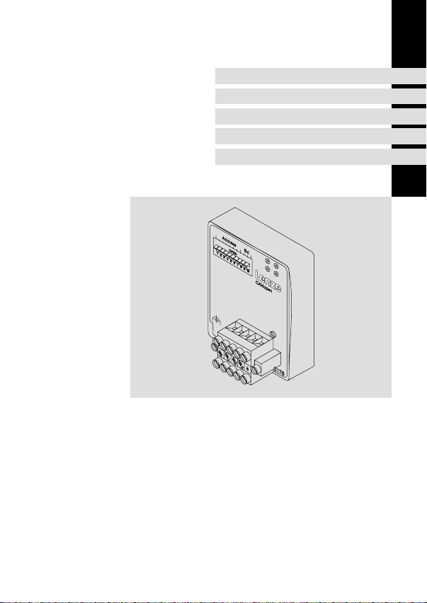
EMF2178IB
Kommunikationsmodul
Communication module
Module de communication
l
Page 2

, Lesen Sie zuerst diese Anleitung und die Dokumentation zum Grundgerät,
bevor Sie mit den Arbeiten beginnen!
Beachten Sie die enthaltenen Sicherheitshinweise.
, Please read these instructions and the documentation of the standard
device before you start working!
Observe the safety instructions given therein!
, Lire le présent fascicule et la documentation relative à l’appareil de base
avant toute manipulation de l’équipement !
Respecter les consignes de sécurité fournies.
Page 3
EMF2178IB
6
5
Address Bd
GND
CAN_L
0
L
CANopen
CAN_H
SHLD
1
2
3
V+
4
2178
2178CAN003
2102LEC007
Page 4

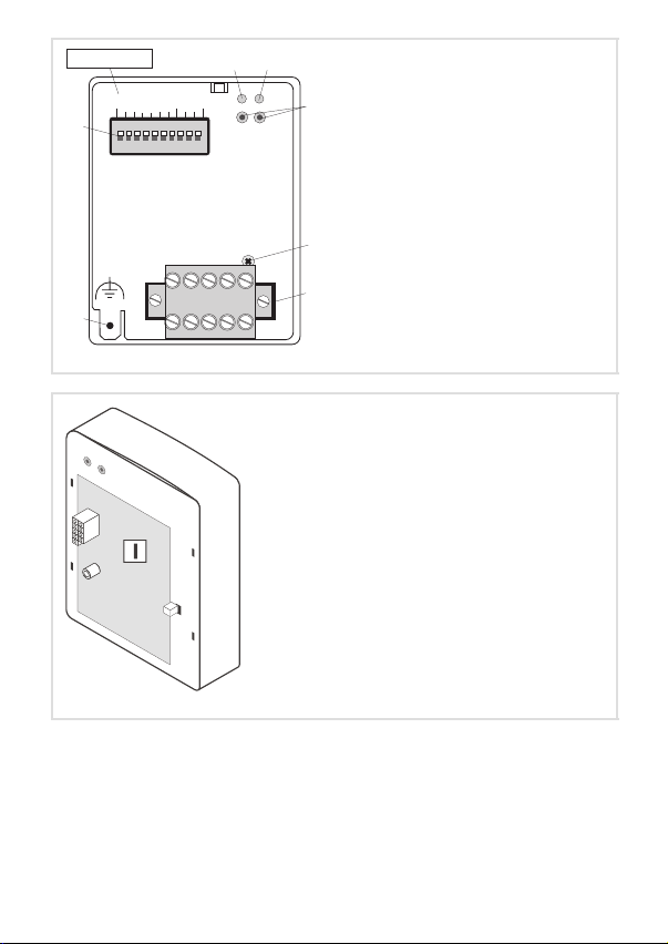
Legende zur Abbildung auf der Ausklappseite
Pos. Beschreibung Ausführliche
Verbindungsstatus zum Grundgerät (zweifarbige LED)
0
Verbindungsstatus zum Feldbus (zweifarbige LED)
1
Betriebszustand des Grundgerätes (grüne und rote Drive−LED)
2
Befestigungsschraube
3
Steckerleiste mit Doppel−Schraubanschluss, 5−polig
4
Anschluss PE−Schirmkabel
5
DIP−Schalter zur Einstellung der
6
l Knotenadresse (Schalter 1 ... 7)
l Übertragungsrate (Schalter 8 ... 10)
Typenschild
8
0Abb. 0Tab. 0
Information
^ 39
^ 19
^ 28
^ 13
4
l
EDKMF2178IB DE/EN/FR 6.0
Page 5

Inhalt i
1 Über diese Dokumentation 6 . . . . . . . . . . . . . . . . . . . . . . . . . . . . . . . . . . . . . . . . . . . .
Verwendete Konventionen 7 . . . . . . . . . . . . . . . . . . . . . . . . . . . . . . . . . . . . . . . . . . . .
Verwendete Hinweise 8 . . . . . . . . . . . . . . . . . . . . . . . . . . . . . . . . . . . . . . . . . . . . . . . .
2 Sicherheitshinweise 10 . . . . . . . . . . . . . . . . . . . . . . . . . . . . . . . . . . . . . . . . . . . . . . . . . .
3 Produktbeschreibung 11 . . . . . . . . . . . . . . . . . . . . . . . . . . . . . . . . . . . . . . . . . . . . . . . .
Bestimmungsgemäße Verwendung 11 . . . . . . . . . . . . . . . . . . . . . . . . . . . . . . . . . . . .
Lieferumfang 12 . . . . . . . . . . . . . . . . . . . . . . . . . . . . . . . . . . . . . . . . . . . . . . . . . . . . . . .
Identifikation 13 . . . . . . . . . . . . . . . . . . . . . . . . . . . . . . . . . . . . . . . . . . . . . . . . . . . . . . .
4 Technische Daten 14 . . . . . . . . . . . . . . . . . . . . . . . . . . . . . . . . . . . . . . . . . . . . . . . . . . . .
Allgemeine Daten und Einsatzbedingungen 14 . . . . . . . . . . . . . . . . . . . . . . . . . . . .
Schutzisolierung 15 . . . . . . . . . . . . . . . . . . . . . . . . . . . . . . . . . . . . . . . . . . . . . . . . . . . . .
Abmessungen 16 . . . . . . . . . . . . . . . . . . . . . . . . . . . . . . . . . . . . . . . . . . . . . . . . . . . . . . .
5 Mechanische Installation 17 . . . . . . . . . . . . . . . . . . . . . . . . . . . . . . . . . . . . . . . . . . . . .
6 Elektrische Installation 18 . . . . . . . . . . . . . . . . . . . . . . . . . . . . . . . . . . . . . . . . . . . . . . .
EMV−gerechte Verdrahtung 18 . . . . . . . . . . . . . . . . . . . . . . . . . . . . . . . . . . . . . . . . . . .
Verdrahtung mit einem Leitrechner 19 . . . . . . . . . . . . . . . . . . . . . . . . . . . . . . . . . . . .
Systembus (CAN) verdrahten 20 . . . . . . . . . . . . . . . . . . . . . . . . . . . . . . . . . . . . . . . . .
Spannungsversorgung 26 . . . . . . . . . . . . . . . . . . . . . . . . . . . . . . . . . . . . . . . . . . . . . . .
7 Inbetriebnahme 28 . . . . . . . . . . . . . . . . . . . . . . . . . . . . . . . . . . . . . . . . . . . . . . . . . . . . .
Einstellmöglichkeiten durch DIP−Schalter 28 . . . . . . . . . . . . . . . . . . . . . . . . . . . . . . .
Vor dem ersten Einschalten 31 . . . . . . . . . . . . . . . . . . . . . . . . . . . . . . . . . . . . . . . . . . .
Erstes Einschalten 32 . . . . . . . . . . . . . . . . . . . . . . . . . . . . . . . . . . . . . . . . . . . . . . . . . . .
Antrieb über das Kommunikationsmodul freigeben 33 . . . . . . . . . . . . . . . . . . . . . . .
8 Kommunikationsmodul EMF2172IB (CAN) ersetzen 36 . . . . . . . . . . . . . . . . . . . . . . .
9 Diagnose 39 . . . . . . . . . . . . . . . . . . . . . . . . . . . . . . . . . . . . . . . . . . . . . . . . . . . . . . . . . . .
LED−Statusanzeigen 39 . . . . . . . . . . . . . . . . . . . . . . . . . . . . . . . . . . . . . . . . . . . . . . . . .
EDKMF2178IB DE/EN/FR 6.0
l
5
Page 6

1 Über diese Dokumentation
1 Über diese Dokumentation
Inhalt
Diese Dokumentation enthält ...
ƒ Informationen zur mechanischen und elektrischen Installation des
Kommunikationsmoduls;
ƒ Sicherheitshinweise, die Sie unbedingt beachten müssen;
ƒ Angaben über Versionsstände der zu verwendenden Lenze Grundgeräte;
ƒ Informationen zu den LED−Statusanzeigen.
I Tipp!
Weiterführende Informationen zu diesem Kommunikationsmodul finden Sie
im entsprechenden Kommunikationshandbuch.
Die PDF−Datei finden Sie im Download−Bereich unter
http://www.Lenze.com
Zielgruppe
Diese Dokumentation wendet sich an Personen, die das beschriebene Produkt nach Projektvorgabe installieren und in Betrieb nehmen.
Informationen zur Gültigkeit
Die Informationen in dieser Dokumentation sind gültig für folgende Geräte:
ƒ Kommunikationsmodule EMF2178IB (CANopen) ab Version 1x.2x.
I Tipp!
Informationen und Hilfsmittel rund um die Lenze−Produkte finden Sie im
Download−Bereich unter
http://www.Lenze.com
6
l
EDKMF2178IB DE/EN/FR 6.0
Page 7

Über diese Dokumentation
Verwendete Konventionen
Verwendete Konventionen
Diese Dokumentation verwendet folgende Konventionen zur Unterscheidung verschiedener Arten von Information:
Informationsart Auszeichnung Beispiele/Hinweise
Zahlenschreibweise
Dezimaltrennzeichen
Symbole
Seitenverweis
Punkt Es wird generell der Dezimalpunkt
^
verwendet.
Beispiel: 1234.56
Verweis auf eine andere Seite mit zusätzlichen Informationen
Beispiel: ^ 16 = siehe Seite 16
1
EDKMF2178IB DE/EN/FR 6.0
l
7
Page 8

1 Über diese Dokumentation
Verwendete Hinweise
Verwendete Hinweise
Um auf Gefahren und wichtige Informationen hinzuweisen, werden in dieser Dokumentation folgende Piktogramme und Signalwörter verwendet:
Sicherheitshinweise
Aufbau der Sicherheitshinweise:
} Gefahr!
(kennzeichnet die Art und die Schwere der Gefahr)
Hinweistext
(beschreibt die Gefahr und gibt Hinweise, wie sie vermieden werden kann)
Piktogramm und Signalwort Bedeutung
Gefahr von Personenschäden durch gefährliche elektrische Spannung
{ Gefahr!
} Gefahr!
( Stop!
Hinweis auf eine unmittelbar drohende Gefahr, die den
Tod oder schwere Verletzungen zur Folge haben kann,
wenn nicht die entsprechenden Maßnahmen getroffen
werden.
Gefahr von Personenschäden durch eine allgemeine Gefahrenquelle
Hinweis auf eine unmittelbar drohende Gefahr, die den
Tod oder schwere Verletzungen zur Folge haben kann,
wenn nicht die entsprechenden Maßnahmen getroffen
werden.
Gefahr von Sachschäden
Hinweis auf eine mögliche Gefahr, die Sachschäden zur
Folge haben kann, wenn nicht die entsprechenden Maßnahmen getroffen werden.
8
l
EDKMF2178IB DE/EN/FR 6.0
Page 9

Anwendungshinweise
Piktogramm und Signalwort Bedeutung
Über diese Dokumentation
Verwendete Hinweise
1
) Hinweis!
I Tipp!
,
Wichtiger Hinweis für die störungsfreie Funktion
Nützlicher Tipp für die einfache Handhabung
Verweis auf andere Dokumentation
EDKMF2178IB DE/EN/FR 6.0
l
9
Page 10

2 Sicherheitshinweise
2 Sicherheitshinweise
} Gefahr!
Unsachgemäßer Umgang mit dem Kommunikationsmodul und dem
Grundgerät kann schwere Personenschäden und Sachschäden verursachen.
Beachten Sie die in der Dokumentation zum Grundgerät enthaltenen
Sicherheitshinweise und Restgefahren.
( Stop!
Elektrostatische Entladung
Durch elektrostatische Entladung können elektronische Bauteile innerhalb des
Kommunikationsmoduls beschädigt oder zerstört werden.
Mögliche Folgen:
ƒ Das Kommunikationsmodul ist defekt.
ƒ Die Feldbus−Kommunikation ist nicht möglich oder fehlerhaft.
Schutzmaßnahmen
ƒ Befreien Sie sich vor dem Berühren des Moduls von elektrostatischen
Aufladungen.
10
l
EDKMF2178IB DE/EN/FR 6.0
Page 11

Produktbeschreibung
Bestimmungsgemäße Verwendung
3 Produktbeschreibung
Bestimmungsgemäße Verwendung
Das Kommunikationsmodul ...
ƒ ermöglicht die Kommunikation mit Lenze Antriebsreglern über den CAN−Bus mit
dem Kommunikationsprofil CANopen.
ƒ ist ein Betriebsmittel zum Einsatz in industriellen Starkstromanlagen.
ƒ ist eine Zubehör−Baugruppe, die mit folgenden Lenze Antriebsreglern eingesetzt
werden kann:
Gerätereihe Gerätetyp
8200 vector E82xVxxxKxBxxxXX Vx 1x Frequenzumrichter 8200 vector
9300
9300 vector
Servosystem
ECS
Drive PLC EPL10200−xI ... EPL10203−xI 1x 8x Drive PLC
EVS9321−xS ... EVS9332−xS 2x 1x Servo−Umrichter
EVS9321−xK ... EVS9332−xK 2x 1x Servo−Kurvenscheibe
EVS9321−xP ... EVS9332−xP 2x 1x Servo−Positionierregler
EVS9321−xR ... EVS9332−xR 2x 1x Servo−Registerregler
EVS9321−xI ... EVS9332−xI 2x 8x
EVS9321−xT ... EVS9332−xT 2x 8x
EVF9321−xV ... EVF9333−xV 2x 1x
EVF9335−xV ... EVF9338−xV 1x 0x
EVF9381−xV ... EVF9383−xV 1x 0x
ECSxSxxxC4xxxxXX 1A 6x "Speed and Torque"
ECSxPxxxC4xxxxXX 1A 6x "Posi and Shaft"
ECSxMxxxC4xxxxXX 1A 6x "Motion"
ECSxAxxxC4xxxxXX 1A 6x "Application"
1) Betriebssystem−Softwarestände der Antriebsregler
Version
HW SW
Jede andere Verwendung gilt als sachwidrig!
Erläuterung
1)
9300 Servo PLC
Frequenzumrichter 9300 vector
3
EDKMF2178IB DE/EN/FR 6.0
l
11
Page 12
3 Produktbeschreibung
Lieferumfang
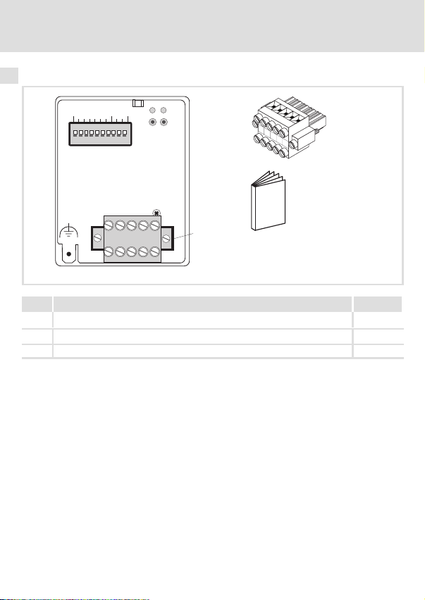
Lieferumfang
0
Address Bd
L
CANopen
4
V-
CAN_L
SHLD
CAN_H
V+
:
CAN_H
CAN_L
SHLD
GND
Pos. Lieferumfang Siehe
Kommunikationsmodul EMF2178IB (CANopen)
0
Steckerleiste mit Doppel−Schraubanschluss, 5−polig
4
Montageanleitung
:
V+
4
2178
2178CAN003, E82ZAFX024
^ 19
12
l
EDKMF2178IB DE/EN/FR 6.0
Page 13
Identifikation
L
Type
Id.-No.
Prod.-No.
Ser.-No.
Produktbeschreibung
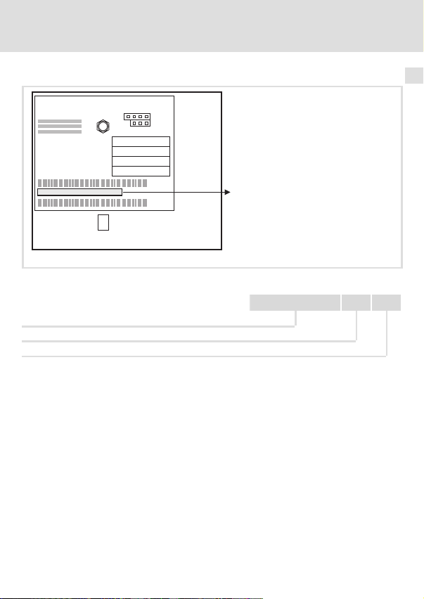
Identifikation
3
E82AF000P0B201XX
Typenschlüssel
Gerätereihe
Hardwarestand
Softwarestand
EDKMF2178IB DE/EN/FR 6.0
l
W
99371BC013
33.2178IB 1x 2x
13
Page 14

4 Technische Daten
Allgemeine Daten und Einsatzbedingungen
4 Technische Daten
Allgemeine Daten und Einsatzbedingungen
Bereich Werte
Bestell−Bezeichnung EMF2178IB
Kommunikationsmedien DIN ISO 11898
Netzwerk−Topologie
Kommunikations−Profil CANopen, DS301 V4.01
Knotenadressen max. 127
Leitungslänge max. 7450 m (abhängig von der Übertragungsrate, ^ 22)
Übertragungsrate [kBit/s] 10, 20, 50, 125, 250, 500, 1000
Spannungsversorgung
Beidseitig abgeschlossene Linie (R = 120 )
Interne oder externe Versorgung möglich bei Grundgeräten:
8200 vector / 93XX / 9300 Servo PLC / Drive PLC / ECSXX
(siehe auch ^ 26)
Externe Versorgung über separates Netzteil:
V+:
U = 24 V DC 10 %
I = 100 mA
GND:
Bezugspotenzial für externe Spannungsversorgung
, Dokumentationen zu Lenze Gerätereihen 8200 vector, 9300 und ECS
Hier finden Sie die Umgebungsbedingungen und Daten zur
Elektromagnetischen Verträglichkeit (EMV), die auch für das
Kommunikationsmodul gelten.
14
l
EDKMF2178IB DE/EN/FR 6.0
Page 15

Technische Daten
Schutzisolierung
Schutzisolierung
Schutzisolierung zwischen Bus und ... Art der Isolierung nach EN 61800−5−1
Bezugserde / PE Betriebsisolierung
externer Versorgung keine Betriebsisolierung
Leistungsteil
l 8200 vector
l 9300 vector, Servo PLC
l Drive PLC
l ECSXX
Steuerklemmen
l 8200 vector
(bei interner Versorgung, ^ 26)
l 8200 vector
(bei externer Versorgung, ^ 27)
l 9300 vector, Servo PLC
l Drive PLC
l ECSXX
doppelte Isolierung
doppelte Isolierung
doppelte Isolierung
doppelte Isolierung
keine Betriebsisolierung
Basisisolierung
Basisisolierung
Basisisolierung
Basisisolierung
4
EDKMF2178IB DE/EN/FR 6.0
l
15
Page 16
4 Technische Daten
Abmessungen
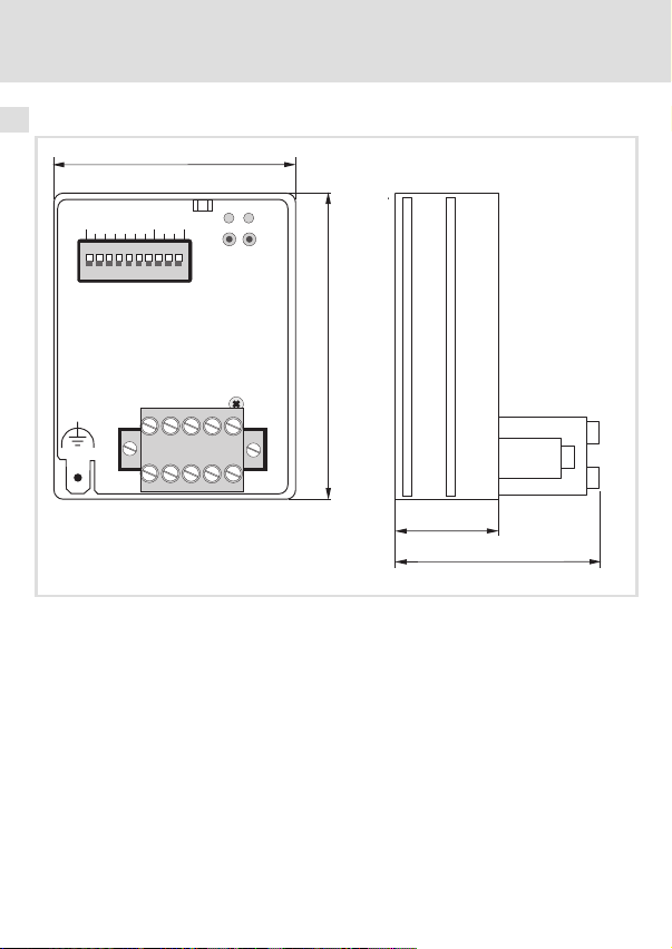
Abmessungen
62
Address Bd
L
CANopen
75
CAN_H
CAN_L
SHLD
GND
Abb. 1 Abmessungen des Kommunikationsmoduls (alle Maße in mm)
V+
2178
18
36
2178CAN003
16
l
EDKMF2178IB DE/EN/FR 6.0
Page 17
Mechanische Installation 5
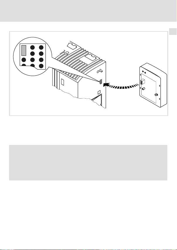
5 Mechanische Installation
2102LEC014
Abb. 2 Kommunikationsmodul aufstecken
ƒ Stecken Sie das Kommunikationsmodul auf das Grundgerät (hier: 8200 vector).
ƒ Schrauben Sie das Kommunikationsmodul mit der Befestigungsschraube auf dem
Grundgerät fest, um eine gute PE−Verbindung sicher zu stellen.
) Hinweis!
Zur internen Versorgung des Kommunikationsmoduls durch den
Frequenzumrichter 8200 vector muss der Jumper in der Schnittstellenöffnung
(siehe Abb. oben) angepasst werden.
Beachten Sie die Hinweise (^ 26).
EDKMF2178IB DE/EN/FR 6.0
l
17
Page 18

6 Elektrische Installation
EMV−gerechte Verdrahtung
6 Elektrische Installation
EMV−gerechte Verdrahtung
Für eine EMV−gerechte Verdrahtung beachten Sie folgende Punkte:
) Hinweis!
ƒ Steuer−/Datenleitungen getrennt von Motorleitungen verlegen.
ƒ Legen Sie die Schirme der Steuer−/Datenleitungen bei digitalen Signalen
beidseitig auf.
ƒ Zur Vermeidung von Potenzialdifferenzen zwischen den
Kommunikationsteilnehmern eine Ausgleichsleitung mit einem
Querschnitt von mindestens 16mm
ƒ Beachten Sie die weiteren Hinweise zur EMV−gerechten Verdrahtung in der
Dokumentation des Grundgerätes.
Vorgehensweise bei der Verdrahtung
1. Bustopologie einhalten, deshalb keine Stichleitungen verwenden.
2. Hinweise und Verdrahtungsvorschriften in den Unterlagen zum Steuerungssystem
beachten.
3. Nur Kabel verwenden, die den aufgeführten Spezifikationen entsprechen (^ 21).
4. Zulässige Busleitungslänge einhalten (^ 22)
5. Busabschlusswiderstände von je 120 (Lieferumfang) anschließen:
– nur am physikalisch ersten und letzten Busteilnehmer
– zwischen den Klemmen CAN−LOW und CAN−HIGH
2
einsetzen (Bezug:PE).
.
18
l
EDKMF2178IB DE/EN/FR 6.0
Page 19
Elektrische Installation
Verdrahtung mit einem Leitrechner
Verdrahtung mit einem Leitrechner
{ Gefahr!
Eine zusätzliche Potenzialtrennung installieren, wenn eine sichere
Potenzialtrennung (verstärkte Isolierung) nach EN61800−5−1 notwendig ist.
Hierzu kann z. B. eine Anschaltbaugruppe für den Leitrechner mit einer zusätzlichen Potenzialtrennung verwendet werden (siehe jeweilige Herstellerangaben).
Berücksichtigen Sie bei der Verdrahtung die Potenzialtrennung der Versorgungsspannung.
Die Versorgungsspannung liegt auf demselben Potenzial wie der Datenbus.
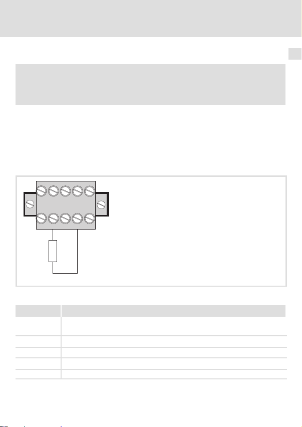
Über die 5−polige Steckerleiste mit Doppel−Schraubanschluss erfolgt
ƒ der Busanschluss (^ 20);
ƒ die externe Spannungsversorgung (^ 27).
CAN_H
CAN_L
SHLD
GND
120W
Abb. 3 5−polige Steckerleiste mit Doppel−Schraubanschluss
Bezeichnung Erläuterung
GND Bezugspotenzial für externe Spannungsversorgung
CAN_L
SHIELD Schirmung
CAN_H
V+ Externe Spannungsversorgung
V+
2178CAN003
Anschluss CAN−GND
Datenleitung / Eingang für Abschlusswiderstand 120
Datenleitung / Eingang für Abschlusswiderstand 120
6
EDKMF2178IB DE/EN/FR 6.0
l
19
Page 20
6 Elektrische Installation
Systembus (CAN) verdrahten
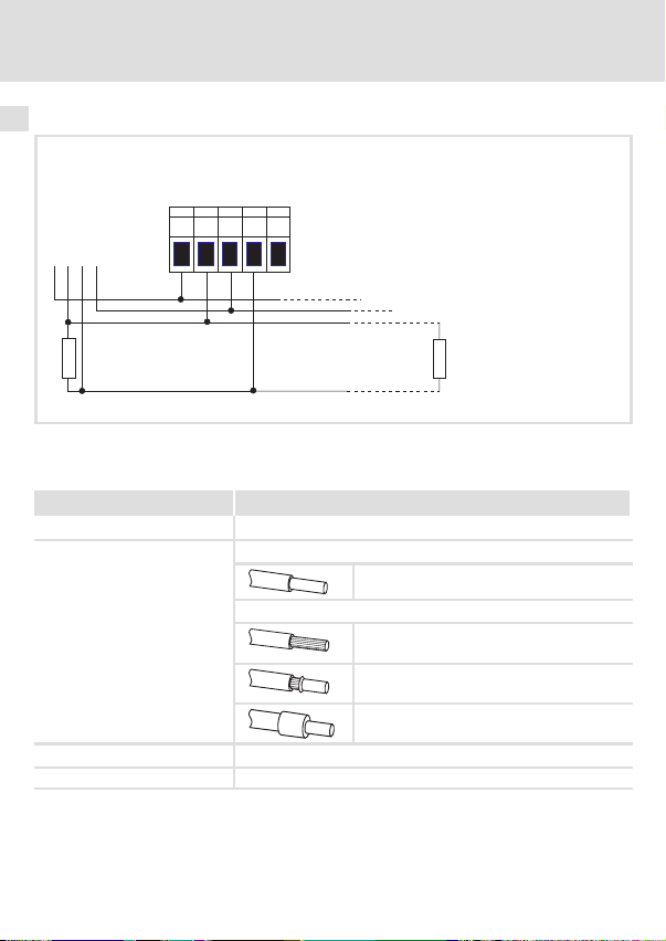
Systembus (CAN) verdrahten
SHLD
CAN_H
V+
GND
CAN_L
CAN
+
GND
LOW
HIGH
120 W
Abb. 4 Anschluss an die Steckerleiste
Daten der Anschlussklemmen
Bereich Werte
Elektrischer Anschluss Steckerleiste mit Schraubanschluss
Anschlussmöglichkeiten
Anzugsmoment 0.5 ... 0.6 Nm (4.4 ... 5.3 lb−in)
Abisolierlänge 6 mm
starr:
flexibel:
EMF2178IB
GND
+
2
1.5 mm
(AWG 16)
ohne Aderendhülse
2
(AWG 16)
1.5 mm
mit Aderendhülse, ohne Kunststoffhülse
2
(AWG 16)
1.5 mm
mit Aderendhülse, mit Kunststoffhülse
2
(AWG 16)
1.5 mm
120 W
2178CAN002
20
l
EDKMF2178IB DE/EN/FR 6.0
Page 21

Elektrische Installation
Systembus (CAN) verdrahten
Spezifikation des Übertragungskabels
Wir empfehlen CAN−Kabel nach ISO 11898−2 zu verwenden:
CAN−Kabel nach ISO 11898−2
Kabeltyp Paarverseilt mit Abschirmung
Impedanz
Leitungswiderstand/−querschnitt
Kabellänge 300 m 70 m/m / 0.25 0.34 mm2 (AWG22)
Kabellänge 301 1000 m
Signallaufzeit
120 (95 ... 140 )
40 m/m / 0.5 mm
5 ns/m
2
(AWG20)
6
EDKMF2178IB DE/EN/FR 6.0
l
21
Page 22

6 Elektrische Installation
Systembus (CAN) verdrahten
Busleitungslänge
) Hinweis!
ƒ Halten Sie die zulässigen Leitungslängen unbedingt ein.
ƒ Wenn bei gleicher Übertragungsrate die zugehörigen
Gesamtleitungslängen der CAN−Teilnehmer unterschiedlich sind, muss zur
Bestimmung der max. Leitungslänge der kleinere Wert verwendet werden.
ƒ Beachten Sie die Reduzierung der Gesamtleitungslänge aufgrund der
Signalverzögerung des Repeaters.
Gesamtleitungslänge
Durch die Übertragungsrate ist die Gesamtleitungslänge festgelegt.
Übertragungsrate [kBit/s] Max. Buslänge [m]
10 7450
20 3950
50 1550
125 630
250 290
500 120
1000 25
Tab. 1 Gesamtleitungslänge
22
l
EDKMF2178IB DE/EN/FR 6.0
Page 23

Elektrische Installation
Systembus (CAN) verdrahten
Segmentleitungslänge
Die Segmentleitungslänge wird durch den verwendeten Leitungsquerschnitt und die Teilnehmeranzahl festgelegt. Repeater unterteilen die Gesamtleitungslänge in Segmente.
Ohne Repeater ist die Segmentleitungslänge gleich der Gesamtleitungslänge.
Max. Anzahl Teilnehmer je Segment
2 240 m 430 m 650 m 940 m
5 230 m 420 m 640 m 920 m
10 230 m 410 m 620 m 900 m
20 210 m 390 m 580 m 850 m
32 200 m 360 m 550 m 800 m
63 170 m 310 m 470 m 690 m
100 150 m 270 m 410 m 600 m
Tab. 2 Segmentleitungslänge
Beispiel: Auswahlhilfe
Vorgaben
Zu realisierende Gesamtleitungslänge 200 m
Teilnehmeranzahl 63
Ergebnisse
Max. mögliche Übertragungsrate 250 kBit/s
Benötigter Leitungsquerschnitt
(interpoliert)
Leitungsquerschnitt Standard CAN−Kabel
Leitungsquerschnitt
(Interpolation ist zulässig)
2
0.25 mm
(AWG24)
0.5 mm
(AWG21)
(aus Tab. 1 Gesamtleitungslänge hergeleitet)
0.30 mm2 (AWG23)
(aus Tab. 2 Segmentleitungslänge hergeleitet)
0.34 mm2 (AWG22)
(siehe Spezifikation des Übertragungskabels ^ 21)
2
0.75 mm
(AWG19)
2
1.0 mm
(AWG18)
2
6
EDKMF2178IB DE/EN/FR 6.0
l
23
Page 24

6 Elektrische Installation
Systembus (CAN) verdrahten
Repeater−Einsatz prüfen
Vergleichen Sie die Werte aus Tab. 1 Gesamtleitungslänge (^ 22) und Tab. 2 Segmentleitungslänge (^ 23).
ƒ Ist die Summe der Segmentleitungslängen kleiner als die zu realisierende
Gesamtleitungslänge, müssen entweder Repeater eingesetzt werden oder der
Leitungsquerschnitt muss vergrößert werden.
ƒ Wird durch die Verwendung von Repeatern die max. mögliche Gesamtleitungslänge
derart reduziert, dass sie kleiner als die zu realisierende Gesamtleitungslänge ist,
muss entweder der Leitungsquerschnitt vergrößert und die Anzahl der Repeater
reduziert werden oder die Übertragungsrate muss verringert werden.
ƒ Die Verwendung eines weiteren Repeaters wird empfohlen als ...
– Service−Schnittstelle
Vorteil: Ein störungsfreies Ankoppeln im laufenden Bus−Berieb ist möglich.
– Einmess−Schnittstelle
Vorteil: Das Einmess−/Programmiergerät bleibt galvanisch getrennt.
Beispiel
Vorgaben
Zu realisierende Gesamtleitungslänge 450 m
Teilnehmeranzahl 32
Leitungsquerschnitt 0.50 mm2 (AWG 20)
Übertragungsrate 125 kBit/s
Verwendeter Repeater Lenze Repeater EMF2176IB
Reduzierung der max. Gesamtleitungslänge pro Repeater (EMF2176IB)
Ergebnisse
Max. Gesamtleitungslänge 630 m
Max. Segmentleitungslänge 360 m
Vergleich Die max. Segmentleitungslänge ist kleiner als die zu reali-
Folgerung Spätestens nach der ermittelten max. Segmentleitungs-
30 m
(vgl. Tab. 1 Gesamtleitungslänge (^ 22))
(vgl. Tab. 2 Segmentleitungslänge (^ 23))
sierende Gesamtleitungslänge.
länge von 360 m muss ein Repeater eingesetzt werden.
24
l
EDKMF2178IB DE/EN/FR 6.0
Page 25

Elektrische Installation
Systembus (CAN) verdrahten
Ergebnisse mit 1 Repeater
Max. Gesamtleitungslänge 600 m
Max. Segmentleitungslänge 720 m
Vergleich Sowohl die mögliche Gesamtleitungslänge als auch die
Folgerung 1 Repeater reicht aus, um die Gesamtleitungslänge von
(Reduzierung der Gesamtleitungslänge (^ 22) um 30 m)
Segmentleitungslängen sind größer als die zu realisierende
Gesamtleitungslänge.
450 m zu realisieren.
6
EDKMF2178IB DE/EN/FR 6.0
l
25
Page 26
6 Elektrische Installation
Spannungsversorgung
Spannungsversorgung
Interne Spannungsversorgung
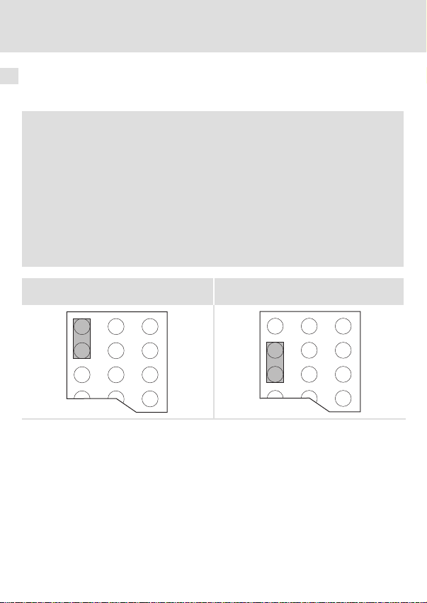
) Hinweis!
Die Vorgabe der internen Spannungsversorgung ist bei Grundgeräten mit
erweiterter AIF−Schnittstellenöffnung (z. B. Frontseite 8200 vector) gegeben.
Die in der Grafik grau hervorgehobene Fläche kennzeichnet die
Jumper−Position.
ƒ Im Auslieferungszustand des Grundgerätes werden diese nicht intern
versorgt.
ƒ Zur internen Spannungsversorgung platzieren Sie den Jumper auf die
unten angegebene Position.
Bei allen anderen Gerätereihen (9300, ECS) ist eine Spannungsversorgung vom
Grundgerät immer vorhanden.
(Nur externe Spannungsversorgung möglich.)
Auslieferungszustand
26
l
Interne Spannungsversorgung
EDKMF2178IB DE/EN/FR 6.0
Page 27

Elektrische Installation
Spannungsversorgung
Externe Spannungsversorgung
) Hinweis!
Verwenden Sie bei externer Spannungsversorgung und bei größeren
Entfernungen zwischen den Schaltschränken in jedem Schaltschrank immer
ein separates und nach EN 61800−5−1 sicher getrenntes Netzteil (SELV/PELV).
Die externe Spannungsversorgung des Kommunikationsmoduls ...
ƒ ist notwendig, wenn beim Ausfall der Versorgung des Grundgerätes die
Kommunikation über den Feldbus bestehen bleiben soll.
ƒ erfolgt über die 2−polige Steckerleiste mit Schraubanschluss (24 V DC):
Klemme Beschreibung
V+ Externe Spannungsversorgung
GND Bezugspotenzial für externe Spannungsversorgung
ƒ Der Zugriff auf Parameter eines vom Netz getrennten Grundgerätes ist nicht
möglich.
U = 24VDC
I = 100 mA
10%
6
EDKMF2178IB DE/EN/FR 6.0
l
27
Page 28

7 Inbetriebnahme
Einstellmöglichkeiten durch DIP−Schalter
7 Inbetriebnahme
Einstellmöglichkeiten durch DIP−Schalter
Über die frontseitig angeordneten DIP−Schalter können eingestellt werden:
ƒ Knotenadresse (Schalter 1 ... 7)
ƒ Übertragungsrate (Schalter 8 ... 10)
Die Lenze−Einstellung aller DIP−Schalter ist OFF.
) Hinweis!
Einstellungen über Codestellen
ƒ In der Lenze−Einstellung ˘ Adressschalter 1 ... 7 = OFF ˘ werden die Werte
aus den Codestellen C1850/C2350 (Knotenadresse) und C1851/C2351
(Übertragungsrate) übernommen.
– Knotenadressen > 99 sind nur per DIP−Schalter einstellbar.
– Die Übertragungsraten 10 kBit/s und 20 kBit/s sind nur per DIP−Schalter
einstellbar.
ƒ Das Beschreiben der Codestellen (z. B. mit GDC über CAN) wirkt sich direkt
auf die Grundgeräte−Codestellen C0009 und C0126 aus.
ƒ Übernahme von Codestellen−Änderungen durch:
– Spannungsversorgung aus− und wieder einschalten;
– "Reset Node" mit C0358 = 1;
– Netzwerkmanagement−Befehl "Reset Communication";
– C2120 (AIF−Steuer−Byte) = 1 setzen.
ƒ Die Codestellen sind inaktiv, wenn vor einem erneuten Netzeinschalten
mindestens ein Adressschalter (1 ... 7) in Stellung ON gesetzt wurde.
28
l
EDKMF2178IB DE/EN/FR 6.0
Page 29
Einstellmöglichkeiten durch DIP−Schalter
Knotenadresse einstellen
BdAddress
Inbetriebnahme
OPEN
OFF
ON
12345678910
Abb. 5 Adressierung über DIP−Schalter
ƒ Die Knotenadressen bei mehreren vernetzten CAN−Teilnehmern müssen sich
voneinander unterscheiden.
ƒ Alle in Stellung ON befindlichen Schalter (1 ... 7) ergeben in der Summe der
Wertigkeiten die gewünschte Knotenadresse.
Beispiel
Schalter Wertigkeit
164OFF
2 32 OFF
3 16 ON
4 8 OFF
5 4 ON
6 2 ON
7 1 ON
Schaltzustand Knotenadresse
16 + 4 + 2 + 1 = 23
) Hinweis!
Schalten Sie die Spannungsversorgung des Kommunikationsmoduls aus und
anschließend wieder ein, um geänderte Einstellungen zu aktivieren.
7
EDKMF2178IB DE/EN/FR 6.0
l
29
Page 30
7 Inbetriebnahme
Einstellmöglichkeiten durch DIP−Schalter
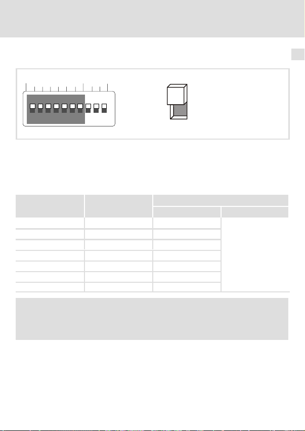
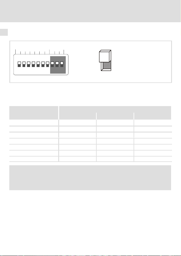
Übertragungsrate einstellen
BdAddress
OPEN
OFF
ON
12345678910
Abb. 6 Einstellen der Übertragungsrate
ƒ Die Übertragungsrate muss bei allen CAN−Teilnehmern identisch eingestellt werden.
ƒ Folgende Übertragungsraten können eingestellt werden:
Übertragungsrate [kBit/s]
8 9 10
10 ON ON OFF
20 ON OFF ON
50 OFF ON ON
125 OFF ON OFF
250 OFF OFF ON
500 OFF OFF OFF
1000 ON OFF OFF
Schalter
) Hinweis!
Schalten Sie die Spannungsversorgung des Kommunikationsmoduls aus und
anschließend wieder ein, um geänderte Einstellungen zu aktivieren.
30
l
EDKMF2178IB DE/EN/FR 6.0
Page 31

Inbetriebnahme
Vor dem ersten Einschalten
Vor dem ersten Einschalten
( Stop!
Bevor Sie das Grundgerät mit dem Kommunikationsmodul erstmalig
einschalten, überprüfen Sie
ƒ die gesamte Verdrahtung auf Vollständigkeit, Kurzschluss und Erdschluss.
ƒ ob das Bussystem beim physikalisch ersten und letzten Busteilnehmer
durch den Busabschlusswiderstand abgeschlossen ist.
7
EDKMF2178IB DE/EN/FR 6.0
l
31
Page 32

7 Inbetriebnahme
Erstes Einschalten
Erstes Einschalten
) Hinweis!
Halten Sie die Inbetriebnahmeschritte in der vorgegebenen Reihenfolge ein.
1. Das Grundgerät und ggf. die externe Spannungsversorgung des
Kommunikationsmoduls einschalten.
– Die grüne LED 0 auf der Frontseite des Kommunikationsmoduls leuchtet.
– Die Status−LED des Grundgerätes (Drive−LED) 2 muss leuchten oder blinken. Die
Bedeutung der Signalisierung finden Sie in der Dokumentation des Grundgerätes.
2. Sie können jetzt mit dem Antrieb kommunizieren, d. h.
– alle Parameter (SDO) können gelesen werden;
– alle beschreibbaren Parameter (SDO) können überschrieben werden.
3. Nach einem Statuswechsel ("Operational") können Prozessdaten mit dem Antrieb
ausgetauscht werden.
2172CAN000D
Abb. 7 LEDs des Kommunikationsmoduls
32
l
EDKMF2178IB DE/EN/FR 6.0
Page 33

Antrieb über das Kommunikationsmodul freigeben
Antrieb über das Kommunikationsmodul freigeben
) Hinweis!
ƒ Während des Betriebs kann das Umstecken des Kommunikationsmoduls
auf einen anderen Antriebsregler zu undefinierten Betriebszuständen
führen.
ƒ Beachten Sie die Informationen zur CAN−Konfiguration und Reglerfreigabe
in der Dokumentation des entsprechenden Antriebsreglers.
8200 vector über das Kommunikationsmodul freigeben
Schritt Vorgehensweise Bemerkungen
Inbetriebnahme
1. C0001 von
"0" auf "3" stellen
2. Klemme 28 auf
HIGH−Pegel legen
3. Eingangsklemme für
QSP auf HIGH−Pegel
legen
4. Der Antriebsregler nimmt nun Parameter− und Prozessdaten an.
Der Lenze−Parameter C0001 (Bedienungsart) kann mit dem GDC,
Keypad XT oder direkt über CANopen eingestellt werden.
Beispiel zur Einstellung direkt über CANopen:
Write (C0001 = 3)
l Index = 5FFE
l Subindex: 0
l Wert: 30000
Die Klemme 28 (Reglerfreigabe) ist immer aktiv und muss während
des CANopen−Betriebs auf HIGH−Pegel liegen. Andernfalls kann der
Antriebsregler über CANopen nicht freigegeben werden.
Die Funktion QSP (Schnellhalt) ist immer aktiv. Falls QSP auf eine
Eingangsklemme konfiguriert ist (Lenze−Einstellung: nicht belegt),
muss diese während des CANopen−Betriebs auf HIGH−Pegel liegen.
(resultiert aus: 5FFF
hex
(resultiert aus: C0001 = 3 x 10000)
dec
− (C0001)
hex
hex
7
;)
EDKMF2178IB DE/EN/FR 6.0
l
33
Page 34

7 Inbetriebnahme
Antrieb über das Kommunikationsmodul freigeben
93XX über das Kommunikationsmodul freigeben
Schritt Vorgehensweise Bemerkungen
1. C0005 auf den Wert
"xxx3" einstellen
2. C0142 = 0 einstellen Siehe "Schutz vor unkontrolliertem Wiederanlauf" (^ 35).
3. Klemme 28 auf
HIGH−Pegel legen
4. Klemme E1 auf
HIGH−Pegel legen
5. Klemme X5/A1 verbinden mit
l X5/28 und
l X5/E1
6. Der Antriebsregler nimmt nun Parameter− und Prozessdaten an.
ECSXX über das Kommunikationsmodul freigeben
Schritt Vorgehensweise Bemerkungen
1. Steuerschnittstelle
"AIF" über Codestelle
wählen.
2. C0142 = 0 einstellen Siehe "Schutz vor unkontrolliertem Wiederanlauf" (^ 35).
3. Klemme X6/SI1 und
X6/SI2 auf HIGH−Pegel legen
4. Der Antriebsregler nimmt nun Parameter− und Prozessdaten an.
Der Wert "xxx3" des Lenze−Parameters C0005 (Steuerung des Antriebsregler über CANopen) kann mit dem GDC, Keypad XT oder
direkt über CANopen eingestellt werden.
Beispiel für die erste Inbetriebnahme mit der Signalkonfiguration
"1013":
Write (C0005 = 1013)
l Index = 5FFA
l Subindex: 0
l Wert: 10130000
Die Klemme 28 (Reglerfreigabe) ist immer aktiv und muss während
des CANopen−Betriebs auf HIGH−Pegel liegen. Andernfalls kann der
Antriebsregler über CANopen nicht freigegeben werden.
Bei der Signalkonfiguration C0005 = 1013 ist die Funktion QSP
(Schnellhalt) in Verbindung mit der Rechts−/Links−Umschaltung auf
die digitalen Eingangsklemmen E1 und E2 gelegt und somit immer
aktiv.
Betrifft nur die Signalkonfiguration C0005 = xx13
Bei dieser Signalkonfiguration ist die Klemme A1 als Spannungsausgang geschaltet.
Siehe Dokumentation des entsprechenden ECS−Antriebsreglers.
Die Klemmen X6/SI1 (Reglerfreigabe−/sperre) und X6/SI2 (Impulsfreigabe−/sperre) sind immer aktiv und müssen während des
CANopen−Betriebs auf HIGH−Pegel liegen. Andernfalls kann der
Antriebsregler über CANopen nicht freigegeben werden.
(resultiert aus: 5FFF
hex
(resultiert aus: C0005 = 1013 x 10000)
dec
− (C0005)
hex
hex
)
34
l
EDKMF2178IB DE/EN/FR 6.0
Page 35

Antrieb über das Kommunikationsmodul freigeben
Schutz vor unkontrolliertem Wiederanlauf
) Hinweis!
Aufbau der Kommunikation
Zum Aufbau der Kommunikation ist es beim extern versorgten
Kommunikationsmodul erforderlich, auch das Grundgerät anfangs
einzuschalten.
Die weitere Kommunikation des extern versorgten Moduls bleibt anschließend
unabhängig vom Einschaltzustand des Grundgerätes.
Schutz vor unkontrolliertem Wiederanlauf
Nach einer Störung (z. B. kurzzeitiger Netzausfall) ist der Wiederanlauf eines
Antriebs in manchen Fällen unerwünscht oder sogar unzulässig.
Über C0142 können Sie das Wiederanlaufverhalten des Antriebsreglers
einstellen:
ƒ C0142 = 0 (Lenze−Einstellung)
– Der Antriebsregler bleibt gesperrt (auch wenn die Störung nicht mehr
aktiv ist).
– Der Antrieb läuft kontrolliert an durch explizite Reglerfreigabe:
93XX: Klemme 28 auf HIGH−Pegel legen.
ECSXX: Klemmen X6/SI1 und X6/SI2 auf HIGH−Pegel legen.
ƒ C0142 = 1
– Ein unkontrollierter Anlauf des Antriebs ist möglich.
Inbetriebnahme
7
EDKMF2178IB DE/EN/FR 6.0
l
35
Page 36

8 Kommunikationsmodul EMF2172IB (CAN) ersetzen
8 Kommunikationsmodul EMF2172IB (CAN) ersetzen
Beachten Sie folgende Informationen, wenn Sie das Kommunikationsmodul EMF2172IB
(CAN) durch das EMF2178IB (CANopen) ersetzen:
ƒ Die Kommunikationsmodule haben unterschiedliche Steckerleisten zum Anschluss
der Spannungsversorgung und des Systembus (CAN).
ƒ Die DIP−Schalter der Kommunikationsmodule haben unterschiedliche Belegungen
zur Einstellung der CAN−Knotenadresse und Übertragungsrate (^ 37). Zudem
unterscheidet sich der einstellbare CAN−Adressbereich:
Kommunikationsmodul CAN−Adressbereich DIP−Schalter
EMF2172IB (CAN) 1 ... 63 S4 ... S9
EMF2178IB (CANopen) 1 ... 127 S1 ... S7
ƒ Die Aktivierung des 2. SDO−Kanals erfolgt ˘ je nach eingesetztem Grundgerät ˘ über
die Codestelle C1865/1 oder C2365/1 (^ 38).
Verdrahtung ändern
Die folgende Abbildung zeigt, wie Sie die bisherige Verdrahtung nun beim Kommunikationsmodul EMF2178IB vornehmen müssen.
Address Bd
36
1 - 3
4 - 9
addressbaud
24 V DC
+
-
21
L
CAN
Low
GND
5
4
3
High
2172
6
l
L
CANopen
CAN_H
CAN_L
SHLD
GND
2
4
V+
2178
1
3
5
6
EDKMF2178IB DE/EN/FR 6.0
2178CAN010
Page 37
Kommunikationsmodul EMF2172IB (CAN) ersetzen 8
DIP−Schaltereinstellungen
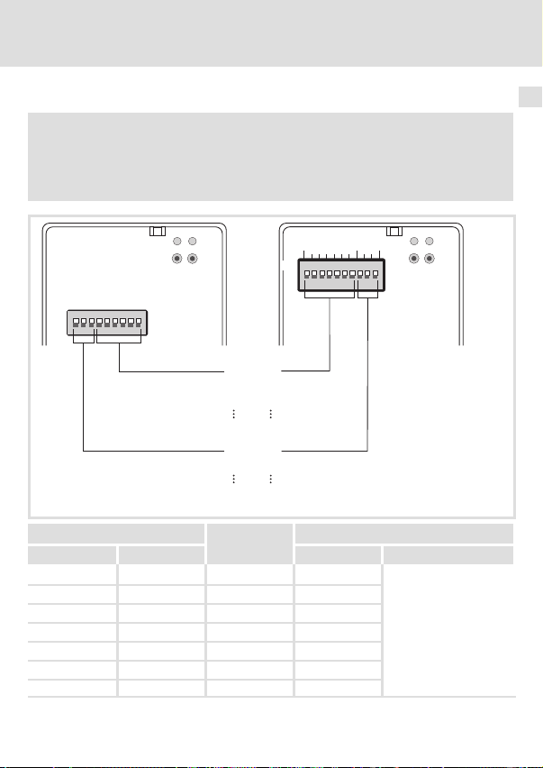
) Hinweis!
Am Kommunikationsmodul EMF2178IB muss der Schalter S1 = OFF
(Lenze−Einstellung) gesetzt bleiben. (Eine Adresseinstellung > 63 ist bei
EMF2172IB nicht möglich gewesen.)
Address Bd
L
1 - 3
ON
OFF
Schalter Wertigkeit
EMF2172IB EMF2178IB Schaltzustand CAN−Knotenadresse
−S164 OFF
S9 S2 32 OFF
S8 S3 16 ON
S7 S4 8 OFF
S6 S5 4 ON
S5 S6 2 ON
S4 S7 1 ON
CAN
4 - 9
addressbaud
S9 S2
S4 S7
S3 S8
S1 S10
OFF
ON
Address
- - W S1 = OFF
W
W
Baudrate
W
W
78
1
10
L
CANopen
Beispiel
2178CAN011
16 + 4 + 2 + 1 = 23
EDKMF2178IB DE/EN/FR 6.0
l
37
Page 38

8 Kommunikationsmodul EMF2172IB (CAN) ersetzen
2. SDO−Kanal aktivieren
Stellen Sie ˘ je nach eingesetztem Grundgerät ˘ die Codestelle C1865/1 oder C2365/1 ein,
um den 2. SDO−Kanal zu aktivieren.
Einstellungen mit GDC/Keypad XT bei diesen Grundgeräten:
EVS 93xx−ES
EVS 93xx−EP
EVS 93xx−EK
EVS 93xx−ER
EVF 93xx−EV
E82EVxxx
1. Kommunikationsmodul EMF2178IB auf das
Grundgerät stecken.
2. Mit dem GDC die Codestelle C1865/1 = 1 set-
zen.
Die Einstellung wird hierbei direkt im Kommunikationsmodul netzausfallsicher gespeichert.
Beim Einsatz der o. g. Grundgeräte kann die
Einstellung auch vorab erfolgen.
EVS 93xx−EI
EVS 93xx−ET
EPL−10200
ECSxS/P/M/A
Mit dem GDC oder Keypad XT die Grundgeräte−
Codestelle C2365/1 = 1 setzen und netzausfallsicher speichern.
Nach Netz−Einschalten eines der o. g. Grundgeräte oder Aufstecken des Kommunikationsmoduls EMF2178IB wird der Inhalt von C2365 in das
Kommunikationsmodul geschrieben.
38
l
EDKMF2178IB DE/EN/FR 6.0
Page 39

9 Diagnose
LED−Statusanzeigen
Pos. Statusanzeige (LED) Beschreibung
Verbindungsstatus zum Grundgerät, zweifarbige LED (grün/rot)
0
AUS
GRÜN
Blinken Das Kommunikationsmodul ist mit Spannung versorgt, hat
Konstantes Leuchten
ROT
Konstantes Leuchten
Blinken
Dauerhaft:
1 x Blinken:
2 x Blinken:
l Das Kommunikationsmodul wird nicht mit Spannung
versorgt.
l Die externe Spannungsversorgung ist ausgeschaltet.
aber keine Verbindung zum Grundgerät.
Ursache:
Das Grundgerät ist ...
l abgeschaltet;
l in der Initialisierungsphase;
l nicht vorhanden.
Das Kommunikationsmodul ist mit Spannung versorgt und
hat eine Verbindung zum Grundgerät.
Der CANopen−Betrieb nicht möglich.
l Parameter werden auf die Lenze−Einstellung zurückge-
setzt.
l Der CANopen−Betrieb ist möglich.
l Beim Speichern eines Wertes trat ein Fehler auf.
l Der CANopen−Betrieb ist möglich.
l Die Knotenadresse/Übertragungsrate konnte nicht aus
C1850/C2350 oder C1851/C2351 übernommen werden.
Diagnose
LED−Statusanzeigen
9
EDKMF2178IB DE/EN/FR 6.0
l
39
Page 40

9 Diagnose
LED−Statusanzeigen
Pos. Statusanzeige (LED) Beschreibung
Verbindungsstatus zum Feldbus, zweifarbige LED (grün/rot)
1
AUS
GRÜN
ROT
Konstantes Leuchten ROT
Keine Verbindung zum Master
CANopen−Zustand ("Z")
CANopen−Fehler ("F")
Z: Bus Off
Blinken GRÜN im 0.2 s−Takt
GRÜN im 0.2 s−Takt
1 x Blinken ROT, 1 s AUS
Blinken GRÜN im 0.2 s−Takt
2 x Blinken ROT, 1 s AUS
Konstantes Leuchten GRÜN
Konstantes Leuchten GRÜN
1 x Blinken ROT, 1 s AUS
Konstantes Leuchten GRÜN
2 x Blinken ROT, 1 s AUS
Konstantes Leuchten GRÜN
3 x Blinken ROT, 1 s AUS
Blinken GRÜN im 1 s−Takt
Blinken GRÜN im 1 s−Takt
1 x Blinken ROT, 1 s AUS
Blinken GRÜN im 1 s−Takt
2 x Blinken ROT, 1 s AUS
Z: Pre−Operational, F: keine
Z: Pre−Operational, F: Warning Limit reached
Z: Pre−Operational, F: Node Guard Event
Z: Operational, F: keine
Z: Operational, Störung: Warning Limit reached
Z: Operational, F: Node Guard Event
Z: Operational, F: Sync Message Error
Z: Stopped, F: keine
Z: Stopped, F: Warning Limit reached
Z: Stopped, F: Node Guard Event
Pos. Statusanzeige (LED) Beschreibung
Grüne und rote Drive−LED Betriebszustand des Grundgerätes
2
40
(siehe Dokumentation des Grundgerätes)
l
EDKMF2178IB DE/EN/FR 6.0
Page 41

Diagnose
LED−Statusanzeigen
9
EDKMF2178IB DE/EN/FR 6.0
l
41
Page 42

Legend for fold−out page
Pos. Description Detailed
Connection status to standard device (two−colour LED)
0
Connection status to fieldbus (two−colour LED)
1
Operating status of standard device (green and red Drive LED)
2
Fixing screw
3
Plug connector with double screw connection, 5−pole
4
PE shield cable connection
5
DIP switches for setting the
6
l node address (switches 1 ... 7)
l baud rate (switches 8 ... 10)
Nameplate
8
0Fig. 0Tab. 0
information
^ 77
^ 57
^ 66
^ 51
42
l
EDKMF2178IB DE/EN/FR 6.0
Page 43

Contents i
1 About this documentation 44 . . . . . . . . . . . . . . . . . . . . . . . . . . . . . . . . . . . . . . . . . . . .
Conventions used 45 . . . . . . . . . . . . . . . . . . . . . . . . . . . . . . . . . . . . . . . . . . . . . . . . . . . .
Notes used 46 . . . . . . . . . . . . . . . . . . . . . . . . . . . . . . . . . . . . . . . . . . . . . . . . . . . . . . . . .
2 Safety instructions 48 . . . . . . . . . . . . . . . . . . . . . . . . . . . . . . . . . . . . . . . . . . . . . . . . . . .
3 Product description 49 . . . . . . . . . . . . . . . . . . . . . . . . . . . . . . . . . . . . . . . . . . . . . . . . . .
Application as directed 49 . . . . . . . . . . . . . . . . . . . . . . . . . . . . . . . . . . . . . . . . . . . . . .
Scope of supply 50 . . . . . . . . . . . . . . . . . . . . . . . . . . . . . . . . . . . . . . . . . . . . . . . . . . . . . .
Identification 51 . . . . . . . . . . . . . . . . . . . . . . . . . . . . . . . . . . . . . . . . . . . . . . . . . . . . . . .
4 Technical data 52 . . . . . . . . . . . . . . . . . . . . . . . . . . . . . . . . . . . . . . . . . . . . . . . . . . . . . . .
General data and operating conditions 52 . . . . . . . . . . . . . . . . . . . . . . . . . . . . . . . .
Protective insulation 53 . . . . . . . . . . . . . . . . . . . . . . . . . . . . . . . . . . . . . . . . . . . . . . . . .
Dimensions 54 . . . . . . . . . . . . . . . . . . . . . . . . . . . . . . . . . . . . . . . . . . . . . . . . . . . . . . . . .
5 Mechanical installation 55 . . . . . . . . . . . . . . . . . . . . . . . . . . . . . . . . . . . . . . . . . . . . . . .
6 Electrical installation 56 . . . . . . . . . . . . . . . . . . . . . . . . . . . . . . . . . . . . . . . . . . . . . . . . .
Wiring according to EMC 56 . . . . . . . . . . . . . . . . . . . . . . . . . . . . . . . . . . . . . . . . . . . . . .
Wiring to a host 57 . . . . . . . . . . . . . . . . . . . . . . . . . . . . . . . . . . . . . . . . . . . . . . . . . . . . .
Wiring of system bus (CAN) 58 . . . . . . . . . . . . . . . . . . . . . . . . . . . . . . . . . . . . . . . . . . .
Voltage supply 64 . . . . . . . . . . . . . . . . . . . . . . . . . . . . . . . . . . . . . . . . . . . . . . . . . . . . .
7 Commissioning 66 . . . . . . . . . . . . . . . . . . . . . . . . . . . . . . . . . . . . . . . . . . . . . . . . . . . . .
Possible settings via DIP switch 66 . . . . . . . . . . . . . . . . . . . . . . . . . . . . . . . . . . . . . . .
Before switching on 69 . . . . . . . . . . . . . . . . . . . . . . . . . . . . . . . . . . . . . . . . . . . . . . . . .
Initial switch−on 70 . . . . . . . . . . . . . . . . . . . . . . . . . . . . . . . . . . . . . . . . . . . . . . . . . . . . .
Enable drive via the communication module 71 . . . . . . . . . . . . . . . . . . . . . . . . . . . . .
8 Replacing the EMF2172IB communication module (CAN) 74 . . . . . . . . . . . . . . . . . . .
9 Diagnostics 77 . . . . . . . . . . . . . . . . . . . . . . . . . . . . . . . . . . . . . . . . . . . . . . . . . . . . . . . . .
LED status displays 77 . . . . . . . . . . . . . . . . . . . . . . . . . . . . . . . . . . . . . . . . . . . . . . . . . .
EDKMF2178IB DE/EN/FR 6.0
l
43
Page 44

1 About this documentation
1 About this documentation
Contents
This documentation contains ...
ƒ information on the mechanical and electrical installation of the communication
module;
ƒ safety instructions which must be observed by all means;
ƒ information about versions of the Lenze standard devices to be used;
ƒ Information on the LED status displays.
I Tip!
Further information regarding this communication module can be found in
the corresponding communication manual.
The PDF file can be found in the download area at
http://www.Lenze.com
Target group
This documentation is intended for persons who install and commission the described
product according to the project requirements.
Validity information
The information given in this documentation is valid for the following devices:
ƒ EMF2178IB communication modules (CANopen) as of version 1x.2x.
I Tip!
Information and auxiliary devices related to the Lenze products can be found
in the download area at
http://www.Lenze.com
44
l
EDKMF2178IB DE/EN/FR 6.0
Page 45

About this documentation
Conventions used
Conventions used
This documentation uses the following conventions to distinguish between different types
of information:
Type of information Identification Examples/notes
Numbers
Decimal separator
Symbols
Page reference
Point The decimal point is used throughout
^
this documentation.
Example: 1234.56
Reference to another page with
additional information
Example: ^ 16 = see page 16
1
EDKMF2178IB DE/EN/FR 6.0
l
45
Page 46

1 About this documentation
Notes used
Notes used
The following pictographs and signal words are used in this documentation to indicate
dangers and important information:
Safety instructions
Structure of safety instructions:
} Danger!
(characterises the type and severity of danger)
Note
(describes the danger and gives information about how to prevent dangerous
situations)
Pictograph and signal word Meaning
Danger of personal injury through dangerous electrical
voltage.
{ Danger!
} Danger!
( Stop!
Reference to an imminent danger that may result in
death or serious personal injury if the corresponding
measures are not taken.
Danger of personal injury through a general source of
danger.
Reference to an imminent danger that may result in
death or serious personal injury if the corresponding
measures are not taken.
Danger of property damage.
Reference to a possible danger that may result in
property damage if the corresponding measures are not
taken.
46
l
EDKMF2178IB DE/EN/FR 6.0
Page 47

Application notes
Pictograph and signal word Meaning
About this documentation
Notes used
1
) Note!
I Tip!
,
Important note to ensure troublefree operation
Useful tip for simple handling
Reference to another documentation
EDKMF2178IB DE/EN/FR 6.0
l
47
Page 48

2 Safety instructions
2 Safety instructions
} Danger!
Inappropriate handling of the communication module and the standard device
can cause serious personal injury and material damage.
Observe the safety instructions and residual hazards described in the
documentation for the standard device.
( Stop!
Electrostatic discharge
Electronic components of the communication module can be damaged or
destroyed through electrostatic discharge.
Possible consequences:
ƒ The communication module is damaged.
ƒ Fieldbus communication is not possible or faulty.
Protective measures
ƒ Discharge electrostatic charges before touching the module.
48
l
EDKMF2178IB DE/EN/FR 6.0
Page 49

Product description
Application as directed
3 Product description
Application as directed
The communication module ...
ƒ enables communication with Lenze controllers over the CAN bus with the CANopen
communication profile.
ƒ is a device intended for use in industrial power systems.
ƒ is an accessory module for use in conjunction with the following Lenze controllers:
Series Device type
8200 vector E82xVxxxKxBxxxXX Vx 1x 8200 vector frequency inverter
9300
9300 vector
ECS servo
system
Drive PLC EPL10200−xI ... EPL10203−xI 1x 8x Drive PLC
EVS9321−xS ... EVS9332−xS 2x 1x Servo inverter
EVS9321−xK ... EVS9332−xK 2x 1x Servo cam profiler
EVS9321−xP ... EVS9332−xP 2x 1x Servo position controller
EVS9321−xR ... EVS9332−xR 2x 1x Servo register controller
EVS9321−xI ... EVS9332−xI 2x 8x
EVS9321−xT ... EVS9332−xT 2x 8x
EVF9321−xV ... EVF9333−xV 2x 1x
EVF9335−xV ... EVF9338−xV 1x 0x
EVF9381−xV ... EVF9383−xV 1x 0x
ECSxSxxxC4xxxxXX 1A 6x "Speed and Torque"
ECSxPxxxC4xxxxXX 1A 6x "Posi and Shaft"
ECSxMxxxC4xxxxXX 1A 6x "Motion"
ECSxAxxxC4xxxxXX 1A 6x "Application"
1) Operating system software versions of the controllers
Version
HW SW
Any other use shall be deemed inappropriate!
Explanation
1)
9300 servo PLC
9300 vector frequency inverter
3
EDKMF2178IB DE/EN/FR 6.0
l
49
Page 50

3 Product description
Scope of supply
Scope of supply
0
Address Bd
L
CANopen
4
V-
CAN_L
SHLD
CAN_H
V+
:
CAN_H
CAN_L
SHLD
GND
Pos. Scope of supply See
EMF2178IB communication module (CANopen)
0
Plug connector with double screw connection, 5−pole
4
Mounting Instructions
:
V+
4
2178
2178CAN003, E82ZAFX024
^ 57
50
l
EDKMF2178IB DE/EN/FR 6.0
Page 51

Identification
L
Type
Id.-No.
Prod.-No.
Ser.-No.
Product description
Identification
3
E82AF000P0B201XX
Type code
Series
Hardware version
Software version
EDKMF2178IB DE/EN/FR 6.0
l
W
99371BC013
33.2178IB 1x 2x
51
Page 52

4 Technical data
General data and operating conditions
4 Technical data
General data and operating conditions
Field Values
Order designation EMF2178IB
Communication media DIN ISO 11898
Network topology
Communication profile CANopen, DS301 V4.01
Node addresses Max. 127
Cable length Max. 7450 m (depending on the baud rate, ^ 60)
Baud rate [kbit/s] 10, 20, 50, 125, 250, 500, 1000
Voltage supply
Line terminated at both ends (R = 120 )
Internal or external supply possible for basic devices: 8200 vector /
93XX / 9300 Servo PLC / Drive PLC / ECSXX
(also see ^ 64)
External supply via separate power supply unit:
V+:
V = 24 V DC 10 %
I = 100 mA
GND:
Reference potential for external voltage supply
, Documentation for Lenze series of devices 8200 vector, 9300 and ECS
Here you can find the ambient conditions and the electromagnetic
compatibility (EMC) specifications applying to the communication module.
52
l
EDKMF2178IB DE/EN/FR 6.0
Page 53

Technical data
Protective insulation
Protective insulation
Protective insulation between the bus and ... Type of insulation according to EN 61800−5−1
Reference earth / PE Functional insulation
External supply No functional insulation
Power section
l 8200 vector
l 9300 vector, Servo PLC
l Drive PLC
l ECSXX
Control terminals
l 8200 vector
(with internal supply, ^ 64)
l 8200 vector
(with external supply, ^ 65)
l 9300 vector, Servo PLC
l Drive PLC
l ECSXX
Double insulation
Double insulation
Double insulation
Double insulation
No functional insulation
Basic insulation
Basic insulation
Basic insulation
Basic insulation
4
EDKMF2178IB DE/EN/FR 6.0
l
53
Page 54

4 Technical data
Dimensions
Dimensions
62
Address Bd
L
CANopen
75
CAN_H
CAN_L
SHLD
GND
Fig. 1 Dimensions of the communication module (all dimensions in mm)
V+
2178
18
36
2178CAN003
54
l
EDKMF2178IB DE/EN/FR 6.0
Page 55

Mechanical installation 5
5 Mechanical installation
2102LEC014
Fig. 2 Attaching the communication module
ƒ Plug the communication module onto the standard device (here: 8200 vector).
ƒ Tighten the communication module to the standard device using the fixing screw in
order to ensure a good PE connection.
) Note!
For the internal supply of the communication module by the 8200 vector
frequency inverter the jumper has to be adjusted within the interface opening
(see illustration above).
Observe the notes (^ 64).
EDKMF2178IB DE/EN/FR 6.0
l
55
Page 56

6 Electrical installation
Wiring according to EMC
6 Electrical installation
Wiring according to EMC
For wiring according to EMC requirements observe the following points:
) Note!
ƒ Separate control cables/data lines from motor cables.
ƒ Connect the shields of control cables/data lines at both ends in the case of
digital signals.
ƒ Use an equalizing conductor with a cross−section of at least 16mm
(reference:PE) to avoid potential differences between the bus nodes.
ƒ Observe the other notes concerning EMC−compliant wiring given in the
documentation for the standard device.
Procedure for wiring
1. Observe the bus topology, i.e. do not use stubs.
2. Observe notes and wiring instructions in the documents for the control system.
3. Only use cables corresponding to the listed specifications (^ 59).
4. Observe the permissible bus cable length (^ 60)
5. Connect bus terminating resistors of 120 each (scope of supply):
– only to the physically first and last node
– between the terminals CAN−LOW and CAN−HIGH
.
2
56
l
EDKMF2178IB DE/EN/FR 6.0
Page 57

Electrical installation
Wiring to a host
Wiring to a host
{ Danger!
An additional electrical isolation is required if a safe electrical isolation
(reinforced insulation) to EN61800−5−1 is necessary.
For this purpose for instance an interface module for the master computer with an
additional electrical isolation can be used (see respective manufacturer information).
For wiring observe the electrical isolation of the supply voltage. The supply voltage is on the
same potential as the data bus.
The 5−pole plug connector with double screw connection serves to
ƒ connect the bus (^ 58);
ƒ effect the external voltage supply (^ 65).
CAN_H
CAN_L
SHLD
GND
120W
Fig. 3 5−pole plug connector with double screw connection
Designation Explanation
GND Reference potential for external voltage supply
CAN_L
SHIELD Shielding
CAN_H
V+ External voltage supply
V+
2178CAN003
CAN−GND connection
Data line / input for terminating resistor 120
Data line / input for terminating resistor 120
6
EDKMF2178IB DE/EN/FR 6.0
l
57
Page 58

6 Electrical installation
Wiring of system bus (CAN)
Wiring of system bus (CAN)
SHLD
CAN_H
V+
GND
CAN_L
CAN
+
GND
LOW
HIGH
120 W
Fig. 4 Connection to the plug connector
Terminal data
Area Values
Electrical connection Plug connector with screw connection
Possible connections
Tightening torque 0.5 ... 0.6 Nm (4.4 ... 5.3 lb−in)
Stripping length 6 mm
rigid:
flexible:
EMF2178IB
GND
+
2
1.5 mm
(AWG 16)
without wire end ferrule
2
(AWG 16)
1.5 mm
with wire end ferrule, without plastic sleeve
2
(AWG 16)
1.5 mm
with wire end ferrule, with plastic sleeve
2
(AWG 16)
1.5 mm
120 W
2178CAN002
58
l
EDKMF2178IB DE/EN/FR 6.0
Page 59

Electrical installation
Wiring of system bus (CAN)
Specification of the transmission cable
We recommend the use of CAN cables in accordance with ISO 11898−2:
CAN cable in accordance with ISO 11898−2
Cable type Paired with shielding
Impedance
Cable resistance/cross−section
Cable length 300 m 70 m/m / 0.25 0.34 mm2 (AWG22)
Cable length 301 1000 m
Signal propagation delay
120 (95 ... 140 )
40 m/m / 0.5 mm
5 ns/m
2
(AWG20)
6
EDKMF2178IB DE/EN/FR 6.0
l
59
Page 60

6 Electrical installation
Wiring of system bus (CAN)
Bus cable length
) Note!
ƒ It is absolutely necessary to comply with the permissible cable lengths.
ƒ If the total cable lengths of the CAN nodes differ for the same baud rate,
the smaller value must be used to determine the max. cable length.
ƒ Observe the reduction of the total cable length due to the signal delay of
the repeater.
Total cable length
The baud rate determines the total cable length.
Baud rate [kbps] Max. bus length [m]
10 7450
20 3950
50 1550
125 630
250 290
500 120
1000 25
Tab. 1 Total cable length
60
l
EDKMF2178IB DE/EN/FR 6.0
Page 61

Electrical installation
Wiring of system bus (CAN)
Segment cable length
The segment cable length is determined by the cable cross−section used and by the number
of nodes. Repeaters divide the total cable length into segments. If no repeaters are used, the
segment cable length is identical to the total cable length.
Max. number of
nodes per
segment
2 240 m 430 m 650 m 940 m
5 230 m 420 m 640 m 920 m
10 230 m 410 m 620 m 900 m
20 210 m 390 m 580 m 850 m
32 200 m 360 m 550 m 800 m
63 170 m 310 m 470 m 690 m
100 150 m 270 m 410 m 600 m
Tab. 2 Segment cable length
Example: Selection help
Given
Total cable length to be implemented 200 m
Number of nodes 63
Results
Max. possible baud rate 250 kbps
Required cable cross−section
(interpolated)
Cable cross−section of standard CAN
cable
Cable cross−section
(can be interpolated)
2
0.25 mm
(AWG24)
2
0.5 mm
(AWG21)
(derived from Tab. 1 Total cable length)
0.30 mm2 (AWG23)
(derived from Tab. 2 Segment cable length)
0.34 mm2 (AWG22)
(see specification of the transmission cable ^ 59)
0.75 mm
(AWG19)
2
1.0 mm
(AWG18)
2
6
EDKMF2178IB DE/EN/FR 6.0
l
61
Page 62

6 Electrical installation
Wiring of system bus (CAN)
Checking the use of repeaters
Compare the values derived from Tab. 1 Total cable length (^ 60) and Tab. 2 Segment
cable length (^ 61).
ƒ If the sum of the segment cable lengths is smaller than the total cable length to be
implemented, either repeaters must be used or the cable cross−section must be
increased.
ƒ If the use of repeaters reduces the max. possible total cable length so much that it is
smaller than the total cable length to be implemented, then the cable cross−section
must be increased or less repeaters must be used or the baud rate must be
decreased.
ƒ The use of a further repeater is recommended as ...
– service interface
Advantage: Trouble−free connection during bus operation is possible.
– calibration interface
Advantage: The calibration/programming unit remains electrically isolated.
Example
Given
Total cable length to be implemented 450 m
Number of nodes 32
Cable cross−section 0.50 mm2 (AWG 20)
Baud rate 125 kbps
Repeater used Lenze repeater EMF2176IB
Reduction of the max. total cable
length per repeater (EMF2176IB)
Results
Max. total cable length 630 m
Max. segment cable length 360 m
Comparison The max. segment cable length is smaller than the total
Conclusion A repeater must be installed at the determined max.
30 m
(see Tab. 1 Total cable length (^ 60))
(see Tab. 2 Segment cable length (^ 61))
cable length to be implemented.
segment cable length of 360 m.
62
l
EDKMF2178IB DE/EN/FR 6.0
Page 63

Electrical installation
Wiring of system bus (CAN)
Results with 1 repeater
Max. total cable length 600 m
Max. segment cable length 720 m
Comparison Both the possible total cable length and the segment cable
Conclusion 1 repeater is sufficient to implement the total cable length
(Reduction of the total cable length (^ 60) by 30 m)
lengths are larger than the total cable length to be
implemented.
of 450 m.
6
EDKMF2178IB DE/EN/FR 6.0
l
63
Page 64

6 Electrical installation
Voltage supply
Voltage supply
Internal voltage supply
) Note!
Internal voltage supply has been selected in the case of standard devices with
an extended AIF interface opening (e.g. front of 8200 vector). The area shown
on a grey background in the graphic marks the jumper position.
ƒ By default, this is not supplied internally in the standard device.
ƒ For internal voltage supply place the jumper on the position indicated
below.
In the case of all other device series (9300, ECS), voltage is always supplied
from the standard device.
(Only external voltage supply possible.)
Lenze setting
64
l
Internal voltage supply
EDKMF2178IB DE/EN/FR 6.0
Page 65

Electrical installation
Voltage supply
External voltage supply
) Note!
In the case of an external voltage supply and for greater distances between the
control cabinets, always use a separate power supply unit (SELV/PELV) that is
safely separated in accordance with EN 61800−5−1 in each control cabinet.
The external voltage supply of the communication module ...
ƒ is required if communication via the fieldbus is to be continued in case the supply of
the standard device fails.
ƒ is carried out via the 2−pole plug connector with screw connection (24 V DC):
Terminal Description
V+ External voltage supply
GND Reference potential for external voltage supply
ƒ The parameters of a basic device disconnected from the mains cannot be accessed.
V = 24VDC
I = 100 mA
10%
6
EDKMF2178IB DE/EN/FR 6.0
l
65
Page 66

7 Commissioning
Possible settings via DIP switch
7 Commissioning
Possible settings via DIP switch
The front panel DIP switches serve to set:
ƒ The node address (switches 1 ... 7)
ƒ The baud rate (switches 8 ... 10)
The Lenze setting of all DIP switches is OFF.
) Note!
Settings via codes
ƒ In the Lenze setting ˘ Address switches 1 ... 7 = OFF ˘, the values are
accepted from the codes C1850/C2350 (node address) and C1851/C2351
(baud rate).
– Node addresses > 99 can only be set via DIP switch.
– The baud rates 10 kbps and 20 kbps can only be selected via DIP switch.
ƒ Writing the codes (e.g. with GDC via CAN) has a direct effect on the
standard device codes C0009 and C0126.
ƒ Acceptance of code changes by:
– Switching off and then on again the voltage supply,
– "Reset node" with C0358 = 1;
– Network management command "Reset Communication";
– Set C2120 (AIF control byte) = 1.
ƒ The codes are inactive if at least one address switch (1 ... 7) has been set to
ON position before a renewed mains connection.
66
l
EDKMF2178IB DE/EN/FR 6.0
Page 67

Possible settings via DIP switch
Node address setting
BdAddress
Commissioning
OPEN
OFF
ON
12345678910
Fig. 5 Address assignment via DIP switch
ƒ If several devices are connected to the CAN network, the node addresses must differ
from each other.
ƒ The desired node address results from the sum of the values of switches (1 ... 7) in ON
position.
Example
Switch Value
164OFF
2 32 OFF
3 16 ON
4 8 OFF
5 4 ON
6 2 ON
7 1 ON
Switch position Node address
16 + 4 + 2 + 1 = 23
) Note!
Switch off the voltage supply of the communication module, and then switch
it on again to activate the changed settings.
7
EDKMF2178IB DE/EN/FR 6.0
l
67
Page 68

7 Commissioning
Possible settings via DIP switch
Baud rate setting
BdAddress
OPEN
OFF
ON
12345678910
Fig. 6 Baud rate setting
ƒ The baud rate must be the same for all CAN nodes.
ƒ The following baud rates can be set:
Baud rate [kbps]
8 9 10
10 ON ON OFF
20 ON OFF ON
50 OFF ON ON
125 OFF ON OFF
250 OFF OFF ON
500 OFF OFF OFF
1000 ON OFF OFF
Switch
) Note!
Switch off the voltage supply of the communication module, and then switch
it on again to activate the changed settings.
68
l
EDKMF2178IB DE/EN/FR 6.0
Page 69

Commissioning
Before switching on
Before switching on
( Stop!
Before you switch on the standard device with the communication module for
the first time, check
ƒ the entire wiring for completeness, short circuit and earth fault.
ƒ whether the bus system is terminated through the bus terminating
resistor at the first and last physical node.
7
EDKMF2178IB DE/EN/FR 6.0
l
69
Page 70

7 Commissioning
Initial switch−on
Initial switch−on
) Note!
Follow the commissioning steps in the given order!
1. Switch on the standard device and, if necessary, the external voltage supply of the
communication module.
– The green LED 0 on the front of the communication module is lit.
– The status LED of the standard device (Drive LED) 2 must be lit or blinking. The
meaning of the signalling can be found in the standard device documentation.
2. You can now communicate with the drive, i. e.
– all parameters (SDO) can be read;
– all writable parameters (SDO) can be overwritten.
3. After a state change ("Operational") process data can be exchanged with the drive.
2172CAN000D
Fig. 7 LEDs of the communication module
70
l
EDKMF2178IB DE/EN/FR 6.0
Page 71

Enable drive via the communication module
Enable drive via the communication module
) Note!
ƒ During operation, the plugging of the communication module onto a
different controller may cause undefined operating states.
ƒ Observe the information on the CAN configuration and controller enable in
the documentation of the corresponding controller.
Enable the 8200 vector via the communication module
Step Procedure Comments
Commissioning
1. Set C0001 from
"0" to "3"
2. Assign 28 to HIGH
level
3. Assign input
terminal for QSP to
HIGH level
4. The controller now accepts parameter data and process data.
The Lenze parameter C0001 (operating mode) can be set with the
GDC, keypad XT or directly via CANopen.
Example for direct setting via CANopen:
Write (C0001 = 3)
l Index = 5FFE
l Subindex: 0
l Value: 30000
The terminal 28 (controller enable) is always active and must be
assigned to HIGH level during CANopen operation. Otherwise the
controller cannot be enabled via CANopen.
The QSP function (quick stop) is always active. If QSP is configured to
an input terminal (Lenze setting: Not assigned), it must be assigned
to HIGH level during CANopen operation.
(resulting from: 5FFF
hex
(resulting from: C0001 = 3 x 10000)
dec
− (C0001)
hex
hex
7
;)
EDKMF2178IB DE/EN/FR 6.0
l
71
Page 72

7 Commissioning
Enable drive via the communication module
Enable 93XX via the communication module
Step Procedure Comments
1. Set C0005 to th value
"xxx3"
2. Set C0142 = 0 See "Protection against uncontrolled restart" (^ 73).
3. Assign 28 to HIGH
level
4. Assign terminal E1 to
HIGH level
5. Connect terminal
X5/A1 to
l X5/28 and
l X5/E1
6. The controller now accepts parameter data and process data.
Enable ECSXX via the communication module
Step Procedure Comments
1. Select control
interface "AIF" via
code.
2. Set C0142 = 0 See "Protection against uncontrolled restart" (^ 73).
3. Assign terminals
X6/SI1 and X6/SI2 to
HIGH level
4. The controller now accepts parameter data and process data.
The value "xxx3" of the Lenze parameter C0005 (control of the
controller via CANopen) can be set with the GDC, keypad XT or
directly via CANopen.
Example for the first commissioning with the signal configuration
"1013":
Write (C0005 = 1013)
l Index = 5FFA
l Subindex: 0
l Value: 10130000
The terminal 28 (controller enable) is always active and must be
assigned to HIGH level during CANopen operation. Otherwise the
controller cannot be enabled via CANopen.
If the signal configuration C0005 = 1013, the QSP function (quick
stop) is assigned to the digital input terminals E1 and E2 in
connection with the right/left change−over and thus always active.
Only affects the signal configuration C0005 = xx13
With this signal configuration the terminal A1 is switched as voltage
output.
See documentation of the corresponding ECS controller.
The terminals X6/SI1 (controller enable/inhibit) and X6/SI2 (pulse
enable/inhibit) are always active and must be assigned to HIGH
level during CANopen operation. Otherwise, the controller cannot
be enabled via CANopen.
(resulting from: 5FFF
hex
(resulting from: C0005 = 1013 x 10000)
dec
− (C0005)
hex
hex
)
72
l
EDKMF2178IB DE/EN/FR 6.0
Page 73

Enable drive via the communication module
Protection against uncontrolled restart
) Note!
Establishing communication
If communication is to be established via an externally supplied
communication module, initially the standard device must also be switched
on.
After communication has been established, the externally supplied module is
independent of the power on/off state of the standard device.
Protection against uncontrolled restart
After a fault (e.g. short−term mains failure), a restart of the drive is not always
wanted and − in some cases − even not allowed.
The restart behaviour of the controller can be set in C0142:
ƒ C0142 = 0 (Lenze setting)
– The controller remains inhibited (even if the fault is no longer active).
– The drive starts up in a controlled manner by explicit controller enable:
93XX: Set terminal 28 to HIGH level.
ECSXX: Set terminals X6/SI1 and X6/SI2 to HIGH level.
ƒ C0142 = 1
– An uncontrolled restart of the drive is possible.
Commissioning
7
EDKMF2178IB DE/EN/FR 6.0
l
73
Page 74

8 Replacing the EMF2172IB communication module (CAN)
8 Replacing the EMF2172IB communication module (CAN)
Observe the following information when replacing the EMF2172IB (CAN) communication
module by EMF2178IB (CANopen):
ƒ The communication modules feature different plug connectors for connecting the
voltage supply and the system bus (CAN).
ƒ The DIP switches of the communication modules feature different assignments for
setting the CAN node address and the baud rate (^ 75). Furthermore there are
different adjustable CAN address ranges:
Communication module CAN address range DIP switch
EMF2172IB (CAN) 1 ... 63 S4 ... S9
EMF2178IB (CANopen) 1 ... 127 S1 ... S7
ƒ Depending on the standard device used, the 2. SDO channel is activated via code
C1865/1 or C2365/1 (^ 76).
Changing the wiring
The following illustration shows how you must carry out the previous wiring for the
EMF2178IB communication module now.
Address Bd
74
1 - 3
4 - 9
addressbaud
24 V DC
+
-
21
L
CAN
Low
GND
5
4
3
High
2172
6
l
L
CANopen
CAN_H
CAN_L
SHLD
GND
2
4
V+
2178
1
3
5
6
EDKMF2178IB DE/EN/FR 6.0
2178CAN010
Page 75

Replacing the EMF2172IB communication module (CAN) 8
DIP switch settings
) Note!
On the EMF2178IB communication module, the switch S1 = OFF(Lenze setting)
must remain set. (An address setting > 63 was not possible for EMF2172IB.)
Address Bd
L
1 - 3
ON
OFF
Switch Value
EMF2172IB EMF2178IB Switch position CAN node address
−S164 OFF
S9 S2 32 OFF
S8 S3 16 ON
S7 S4 8 OFF
S6 S5 4 ON
S5 S6 2 ON
S4 S7 1 ON
CAN
4 - 9
addressbaud
S9 S2
S4 S7
S3 S8
S1 S10
OFF
ON
Address
- - W S1 = OFF
W
W
Baudrate
W
W
78
1
10
Example
L
CANopen
2178CAN011
16 + 4 + 2 + 1 = 23
EDKMF2178IB DE/EN/FR 6.0
l
75
Page 76

8 Replacing the EMF2172IB communication module (CAN)
Activate the 2. SDO channel
Depending on the standard device used, set code C1865/1 or C2365/1 to activate the 2. SDO
channel.
Settings via the GDC/XT keypad for these standard devices:
EVS 93xx−ES
EVS 93xx−EP
EVS 93xx−EK
EVS 93xx−ER
EVF 93xx−EV
E82EVxxx
1. Plug the EMF2178IB communication module
onto the standard device.
2. Use the GDC to set code C1865/1 = 1.
The setting is saved with mains failure
protection directly in the communication
module.
When using the standard devices specified
above, the setting can also be carried out
beforehand.
EVS 93xx−EI
EVS 93xx−ET
EPL−10200
ECSxS/P/M/A
Use the GDC or XT keypad to set standard device
code C2365/1 = 1 and save it with mains failure
protection.
After mains connection of one of the standard
devices specified above, or after plugging on the
EMF2178IB communication module, the contents
of C2365 are written to the communication
module.
76
l
EDKMF2178IB DE/EN/FR 6.0
Page 77

9 Diagnostics
LED status displays
Pos. Status display (LED) Description
Connection status to standard device, two−colour LED (green/red)
0
OFF
GREEN
Blinking The communication module is supplied with voltage, but has
Constantly ON The communication module is supplied with voltage and is
RED
Constantly ON CANopen operation impossible.
Blinking
Permanently:
1 x blinking:
2 x blinking:
l The communication module is not supplied with voltage.
l The external voltage supply is switched off.
no connection to the standard device.
Cause:
The standard device is ...
l switched off;
l in the initialisation phase;
l not available.
connected to the standard device.
l Parameters are reset to Lenze setting.
l CANopen operation possible.
l An error occurred while saving a value.
l CANopen operation possible.
l The node address/baud rate from C1850/C2350 or
C1851/C2351 could not be accepted .
Diagnostics
LED status displays
9
EDKMF2178IB DE/EN/FR 6.0
l
77
Page 78

9 Diagnostics
LED status displays
Pos. Status display (LED) Description
Connection status to fieldbus, two−colour LED (green/red)
1
OFF
GREEN
RED
RED constantly on
No connection to the master
CANopen status ("Z")
CANopen error ("F")
Z: Bus off
Blinking GREEN every 0.2 seconds
GREEN every 0.2 seconds
1 x blinking RED, 1 s OFF
Blinking GREEN every 0.2 seconds
2 x blinking RED, 1 s OFF
GREEN constantly on
GREEN constantly on
1 x blinking RED, 1 s OFF
GREEN constantly on
2 x blinking RED, 1 s OFF
GREEN constantly on
3 x blinking RED, 1 s OFF
Blinking GREEN every second
Blinking GREEN every second
1 x blinking RED, 1 s OFF
Blinking GREEN every second
2 x blinking RED, 1 s OFF
Z: Pre−operational, F: None
Z: Pre−operational, F: Warning limit reached
Z: Pre−operational, F: Node guard event
Z: Operational, F: None
Z: Operational, F: Warning limit reached
Z: Operational, F: Node guard event
Z: Operational, F: Sync message error
Z: Stopped, F: None
Z: Stopped, F: Warning limit reached
Z: Stopped, F: Node guard event
Pos. Status display (LED) Description
Green and red Drive LED Operating status of standard device
2
78
(see standard device documentation)
l
EDKMF2178IB DE/EN/FR 6.0
Page 79

Diagnostics
LED status displays
9
EDKMF2178IB DE/EN/FR 6.0
l
79
Page 80

Légende de l’illustration de la page dépliante
Pos. Description Informations
Etat de la liaison avec l’appareil de base (LED bicolore)
0
Etat de la liaison avec le bus de terrain (LED bicolore)
1
Etat de fonctionnement de l’appareil de base (LED Drive rouge et verte)
2
Vis de fixation
3
Bornier double à raccordement par vis, 5 bornes
4
Raccordement de blindage pour câble PE
5
Interrupteurs DIP pour réglage de
6
l l’adresse de noeud (interrupteurs 1 à 7)
l la vitesse de transmission (interrupteurs 8 à 10)
Plaque signalétique
8
0Fig. 0Tab. 0
détaillées
^ 115
^ 95
^ 28
^ 89
80
l
EDKMF2178IB DE/EN/FR 6.0
Page 81

Sommaire i
1 Présentation du document 82 . . . . . . . . . . . . . . . . . . . . . . . . . . . . . . . . . . . . . . . . . . .
Conventions utilisées 83 . . . . . . . . . . . . . . . . . . . . . . . . . . . . . . . . . . . . . . . . . . . . . . .
Consignes utilisées 84 . . . . . . . . . . . . . . . . . . . . . . . . . . . . . . . . . . . . . . . . . . . . . . . . .
2 Consignes de sécurité 86 . . . . . . . . . . . . . . . . . . . . . . . . . . . . . . . . . . . . . . . . . . . . . . .
3 Description du produit 87 . . . . . . . . . . . . . . . . . . . . . . . . . . . . . . . . . . . . . . . . . . . . . .
Utilisation conforme à la fonction 87 . . . . . . . . . . . . . . . . . . . . . . . . . . . . . . . . . . . .
Equipement livré 88 . . . . . . . . . . . . . . . . . . . . . . . . . . . . . . . . . . . . . . . . . . . . . . . . . . .
Identification 89 . . . . . . . . . . . . . . . . . . . . . . . . . . . . . . . . . . . . . . . . . . . . . . . . . . . . . .
4 Spécifications techniques 90 . . . . . . . . . . . . . . . . . . . . . . . . . . . . . . . . . . . . . . . . . . .
Caractéristiques générales et conditions d’utilisation 90 . . . . . . . . . . . . . . . . . . . .
Isolement de protection 91 . . . . . . . . . . . . . . . . . . . . . . . . . . . . . . . . . . . . . . . . . . . . .
Encombrements 92 . . . . . . . . . . . . . . . . . . . . . . . . . . . . . . . . . . . . . . . . . . . . . . . . . . .
5 Installation mécanique 93 . . . . . . . . . . . . . . . . . . . . . . . . . . . . . . . . . . . . . . . . . . . . . .
6 Installation électrique 94 . . . . . . . . . . . . . . . . . . . . . . . . . . . . . . . . . . . . . . . . . . . . . . .
Câblage conforme CEM 94 . . . . . . . . . . . . . . . . . . . . . . . . . . . . . . . . . . . . . . . . . . . . . .
Raccordement à un maître 95 . . . . . . . . . . . . . . . . . . . . . . . . . . . . . . . . . . . . . . . . . . .
Câblage du bus système (CAN) 96 . . . . . . . . . . . . . . . . . . . . . . . . . . . . . . . . . . . . . . .
Alimentation 102 . . . . . . . . . . . . . . . . . . . . . . . . . . . . . . . . . . . . . . . . . . . . . . . . . . . . .
7 Mise en service 104 . . . . . . . . . . . . . . . . . . . . . . . . . . . . . . . . . . . . . . . . . . . . . . . . . . . .
Réglages pouvant être effectués à l’aide des interrupteurs DIP 104 . . . . . . . . . . . . .
Avant la première mise sous tension 107 . . . . . . . . . . . . . . . . . . . . . . . . . . . . . . . . . . .
Première mise en service 108 . . . . . . . . . . . . . . . . . . . . . . . . . . . . . . . . . . . . . . . . . . . .
Déblocage du variateur via le module de communication 109 . . . . . . . . . . . . . . . . . .
8 Remplacement du module de communication EMF2172IB (CAN) 112 . . . . . . . . . . .
9 Diagnostic 115 . . . . . . . . . . . . . . . . . . . . . . . . . . . . . . . . . . . . . . . . . . . . . . . . . . . . . . . .
Affichages d’état par LED 115 . . . . . . . . . . . . . . . . . . . . . . . . . . . . . . . . . . . . . . . . . . .
EDKMF2178IB DE/EN/FR 6.0
l
81
Page 82

1 Présentation du document
1 Présentation du document
Contenu
Ce document contient ...
ƒ des informations sur l’installation mécanique et électrique du module de
communication ;
ƒ des consignes de sécurité qui doivent impérativement être respectées ;
ƒ des indications sur les versions des appareils de base Lenze à utiliser ;
ƒ des informations sur les affichages d’état par LED.
I Conseil !
Pour plus d’informations sur le module de communication, consulter le
manuel de communication correspondant.
Le fichier au format PDF peut être téléchargé à l’adresse suivante :
http://www.Lenze.com
Public visé
Ce document est destiné aux personnes chargées d’installer et de mettre en service le
produit décrit selon les exigences du projet.
Validité
Les informations contenues dans le présent document s’appliquent aux appareils suivants :
ƒ modules de communication EMF2178IB (CANopen) à partir de la version 1x.2x.
I Conseil !
Toutes les informations relatives aux produits Lenze peuvent être téléchargées
sur notre site à l’adresse suivante :
http://www.Lenze.com
82
l
EDKMF2178IB DE/EN/FR 6.0
Page 83

Présentation du document
Conventions utilisées
Conventions utilisées
Pour distinguer les différents types d’information, cette documentation utilise les
conventions suivantes :
Type d’information Aperçu Exemples/remarques
Représentation des chiffres
Séparateur décimal
Pictogrammes
Renvoi à une page
Point Le point décimal est généralement
^
utilisé.
Exemple : 1234.56
Renvoi à une autre page présentant
des informations supplémentaires
Exemple : ^ 16 = voir page 16
1
EDKMF2178IB DE/EN/FR 6.0
l
83
Page 84

1 Présentation du document
Consignes utilisées
Consignes utilisées
Pour indiquer des risques et des informations importantes, la présente documentation
utilise les mots et pictogrammes suivants :
Consignes de sécurité
Présentation des consignes de sécurité
} Danger !
(Le pictogramme indique le type de risque.)
Explication
(L’explication décrit le risque et les moyens de l’éviter.)
Pictogramme et mot associé Explication
Situation dangereuse pour les personnes en raison d’une
tension électrique élevée
{ Danger !
} Danger !
( Stop !
Indication d’un danger imminent qui peut avoir pour
conséquences des blessures mortelles ou très graves en
cas de non−respect des consignes de sécurité
correspondantes
Situation dangereuse pour les personnes en raison d’un
danger d’ordre général
Indication d’un danger imminent qui peut avoir pour
conséquences des blessures mortelles ou très graves en
cas de non−respect des consignes de sécurité
correspondantes
Risques de dégâts matériels
Indication d’un risque potentiel qui peut avoir pour
conséquences des dégâts matériels en cas de non−respect
des consignes de sécurité correspondantes
84
l
EDKMF2178IB DE/EN/FR 6.0
Page 85

Consignes d’utilisation
Pictogramme et mot associé Explication
Présentation du document
Consignes utilisées
1
) Remarque
importante !
I Conseil !
,
Remarque importante pour assurer un fonctionnement
correct
Conseil utile pour faciliter la mise en uvre
Renvoi à une autre documentation
EDKMF2178IB DE/EN/FR 6.0
l
85
Page 86

2 Consignes de sécurité
2 Consignes de sécurité
} Danger !
Toute utilisation non conforme à la fonction du module de communication et
de l’appareil de base risque d’entraîner des blessures graves et des dommages
matériels.
Tenir compte des consignes de sécurité et des dangers résiduels indiqués dans
la documentation de l’appareil de base.
( Stop !
Décharge électrostatique
Des composants électroniques à l’intérieur du module de communication
peuvent être endommagés ou détruits par des décharges électrostatiques.
Risques encourus :
ƒ Le module de communication est endommagé.
ƒ La communication par bus de terrain est impossible ou erronée.
Mesures de protection :
ƒ Se libérer des décharges électrostatiques avant toute manipulation du
module de communication.
86
l
EDKMF2178IB DE/EN/FR 6.0
Page 87

Description du produit
Utilisation conforme à la fonction
3 Description du produit
Utilisation conforme à la fonction
Le module de communication ...
ƒ permet de communiquer avec les variateurs Lenze via le bus CAN suivant le profil de
communication CANopen.
ƒ est un matériel d’exploitation destiné à être utilisé dans les installations industrielles
à courant fort.
ƒ est un module accessoire compatible avec les variateurs Lenze suivants :
Série
d’appareils
8200 vector E82xVxxxKxBxxxXX Vx 1x Convertisseur de fréquence
9300
9300 vector
Système
servo ECS
Drive PLC EPL10200−xI ... EPL10203−xI 1x 8x Drive PLC
Toute autre utilisation est contre−indiquée !
Type d’appareil
EVS9321−xS ... EVS9332−xS 2x 1x Servovariateur
EVS9321−xK ... EVS9332−xK 2x 1x Servovariateur "came"
EVS9321−xP ... EVS9332−xP 2x 1x Servovariateur "positionnement"
EVS9321−xR ... EVS9332−xR 2x 1x Servovariateur "registre"
EVS9321−xI ... EVS9332−xI 2x 8x
EVS9321−xT ... EVS9332−xT 2x 8x
EVF9321−xV ... EVF9333−xV 2x 1x
EVF9335−xV ... EVF9338−xV 1x 0x
EVF9381−xV ... EVF9383−xV 1x 0x
ECSxSxxxC4xxxxXX 1A 6x "Speed and Torque"
ECSxPxxxC4xxxxXX 1A 6x "Posi and Shaft"
ECSxMxxxC4xxxxXX 1A 6x "Motion"
ECSxAxxxC4xxxxXX 1A 6x "Application"
1) Versions logicielles des systèmes d’exploitation des variateurs de vitesse
Version
HW SW
Précisions
1)
8200 vector
9300 Servo PLC
Convertisseur de fréquence
9300 vector
3
EDKMF2178IB DE/EN/FR 6.0
l
87
Page 88

3 Description du produit
Equipement livré
Equipement livré
0
Address Bd
L
CANopen
4
V-
CAN_L
SHLD
CAN_H
V+
:
CAN_H
CAN_L
SHLD
GND
Pos. Équipement livré Voir
Module de communication EMF2178IB (CANopen)
0
Bornier double à fixation par vis, 5 bornes
4
Instructions de montage
:
V+
4
2178
2178CAN003, E82ZAFX024
^ 95
88
l
EDKMF2178IB DE/EN/FR 6.0
Page 89

Identification
L
Type
Id.-No.
Prod.-No.
Ser.-No.
Description du produit
Identification
3
E82AF000P0B201XX
Codification des types
Série d’appareils
Version matérielle
Version logicielle
EDKMF2178IB DE/EN/FR 6.0
l
W
99371BC013
33.2178IB 1x 2x
89
Page 90

4 Spécifications techniques
Caractéristiques générales et conditions d’utilisation
4 Spécifications techniques
Caractéristiques générales et conditions d’utilisation
Domaine Spécifications
Référence de commande EMF2178IB
Support de communication DIN ISO 11898
Topologie du réseau
Profil de communication CANopen, DS301 V4.01
Adresses de noeud 127 max.
Longueur de câble 7450 m (en fonction de la vitesse de transmission, ^ 98)
Vitesse de transmission
[kbits/s]
Alimentation
Ligne fermée aux deux extrémités (R = 120 )
10, 20, 50, 125, 250, 500, 1000
Interne ou externe pour les appareils de base 8200 vector / 93XX /
9300 Servo PLC / Drive PLC / ECSXX
(voir aussi ^ 102)
Alimentation externe via bloc d’alimentation séparé :
V+ :
U = 24 V CC 10 %
I = 100 mA
potentiel de référence pour l’alimentation externe
GND :
, Documentations relatives aux séries d’appareils Lenze 8200 vector, 9300 et
ECS
Ces documentations décrivent les conditions ambiantes et les données de
compatibilité électromagnétique (CEM), qui sont également valables pour le
module de communication.
90
l
EDKMF2178IB DE/EN/FR 6.0
Page 91

Spécifications techniques
Isolement de protection
Isolement de protection
Isolement de protection entre bus et... Type d’isolement selon EN 61800−5−1
terre / PE Isolement fonctionnel
alimentation externe Pas d’isolement fonctionnel
partie puissance
l 8200 vector
l 9300 vector, Servo PLC
l Drive PLC
l ECSXX
borniers de commande
l 8200 vector
(avec alimentation interne, ^ 102)
l 8200 vector
(avec alimentation externe, ^ 103)
l 9300 vector, Servo PLC
l Drive PLC
l ECSXX
Isolement double
Isolement double
Isolement double
Isolement double
Pas d’isolement fonctionnel
Isolement principal
Isolement principal
Isolement principal
Isolement principal
4
EDKMF2178IB DE/EN/FR 6.0
l
91
Page 92

4 Spécifications techniques
Encombrements
Encombrements
62
Address Bd
L
CANopen
75
CAN_H
CAN_L
SHLD
GND
Fig. 1 Encombrements du module de communication (cotes en mm)
V+
2178
18
36
2178CAN003
92
l
EDKMF2178IB DE/EN/FR 6.0
Page 93

Installation mécanique 5
5 Installation mécanique
2102LEC014
Fig. 2 Brancher le module de communication
ƒ Enficher le module de communication dans l’appareil de base (ici : 8200 vector).
ƒ Visser le module de communication sur l’appareil de base à l’aide de la vis de fixation
pour assurer une bonne liaison avec la terre.
) Remarque importante !
Pour l’alimentation interne du module de communication par le convertisseur
de fréquence 8200 vector, le cavalier doit être inséré dans l’ouverture prévue à
cet effet (voir schéma ci−dessus).
Voir également les remarques fournies (^ 102).
EDKMF2178IB DE/EN/FR 6.0
l
93
Page 94

6 Installation électrique
Câblage conforme CEM
6 Installation électrique
Câblage conforme CEM
Pour s’assurer que le câblage est conforme aux exigences à respecter en matière de CEM,
vérifier les points suivants :
) Remarque importante !
ƒ Séparer physiquement les câbles de commande/de données des câbles
moteur.
ƒ Pour les signaux numériques, blinder les câbles de commande et de
données aux deux extrémités.
ƒ Pour éviter les différences de potentiel entre les participants au bus, utiliser
une ligne de compensation d’une section minimale de 16mm
PE).
ƒ Respecter les autres consignes relatives à un câblage conforme CEM
fournies dans la documentation de l’appareil de base.
Procédure à suivre pour le câblage
1. Respecter la topologie de bus : ne pas utiliser de câbles de dérivation.
2. Respecter les indications et prescriptions concernant le câblage fournies dans la
documentation du système de commande.
3. Utiliser uniquement des câbles correspondant aux spécifications fournies (^ 97).
4. Respecter la longueur de câble bus max. admissible (^ 98)
5. Connecter des résistances d’extrémité de bus de 120 chacune (comprises dans la
livraison) :
– uniquement entre le premier et le dernier participant au bus (extrémités
physiques) ;
– entre les bornes CAN−LOW (BAS) et CAN−HIGH (HAUT).
.
2
(référence :
94
l
EDKMF2178IB DE/EN/FR 6.0
Page 95

Installation électrique
Raccordement à un maître
Raccordement à un maître
{ Danger !
Installer une séparation du potentiel supplémentaire si un isolement renforcé
selon EN61800−5−1 est requis.
Le câblage avec le maître peut être réalisé à l’aide d’un module interface avec séparation de
potentiel supplémentaire par exemple (voir les indications du fabricant).
Lors du câblage, tenir compte de la séparation du potentiel de la tension d’alimentation qui
est au même potentiel que le bus de données.
Le bornier double à raccordement par vis, 5 bornes est utilisé pour
ƒ le raccordement du bus (^ 96);
ƒ l’alimentation externe (^ 103).
CAN_H
CAN_L
SHLD
GND
120W
Fig. 3 Bornier double à raccordement par vis, 5 bornes
Désignation Précisions
GND Potentiel de référence pour l’alimentation externe
CAN_L
SHIELD Blindage
CAN_H
V+ Alimentation externe
V+
2178CAN003
Raccordement CAN−GND
Ligne de données/entrée pour la résistance d’extrémité 120
Ligne de données/entrée pour la résistance d’extrémité 120
6
EDKMF2178IB DE/EN/FR 6.0
l
95
Page 96

6 Installation électrique
Câblage du bus système (CAN)
Câblage du bus système (CAN)
SHLD
CAN_H
V+
GND
CAN_L
CAN
+
GND
LOW
HIGH
120 W
Fig. 4 Raccordement au bornier
Spécifications pour bornier de raccordement
Domaine Spécifications
Raccordement électrique Bornier à vis
Possibilités de raccordement
Couple de serrage 0.5... 0.6 Nm (4.4 ... 5.3 lb−in)
Longueur du fil dénudé 6 mm
Fixe :
Souple :
EMF2178IB
GND
1.5 mm
sans embout
1.5 mm
avec embout, sans cosse en plastique
1.5 mm
avec embout et cosse en plastique
1.5 mm
+
2
(AWG 16)
2
(AWG 16)
2
(AWG 16)
2
(AWG 16)
120 W
2178CAN002
96
l
EDKMF2178IB DE/EN/FR 6.0
Page 97

Installation électrique
Câblage du bus système (CAN)
Spécifications du câble de transmission
Il est recommandé d’utiliser des câbles CAN conformes à la norme ISO 11898−2 :
Câbles CAN conformes à la norme ISO 11898−2
Type de câble Paire blindée
Impédance
Résistance et section de câble
Longueur de câble 300 m 70 m/m / 0.25 0.34 mm2 (AWG22)
Longueur de câble 301 1000 m
Temps de parcours du signal
120 (95 ... 140 )
40 m/m / 0.5 mm
5 ns/m
2
(AWG20)
6
EDKMF2178IB DE/EN/FR 6.0
l
97
Page 98

6 Installation électrique
Câblage du bus système (CAN)
Longueur de câble bus
) Remarque importante !
ƒ Respecter impérativement les longueurs de câble autorisées!
ƒ Si la longueur de câble totale pour les différents participants au bus CAN
varie, malgré une vitesse de transmission identique, la longueur de câble
maximale doit être déterminée sur la base de la plus petite valeur.
ƒ Tenir compte de la réduction de la longueur de câble totale en raison du
retard du signal engendré par le répétiteur.
Longueur de câble totale
La longueur totale de câble est déterminée par la vitesse de transmission.
Vitesse de transmission [kbits/s] Longueur de câble bus max. [m]
10 7450
20 3950
50 1550
125 630
250 290
500 120
1000 25
Tab. 1 Longueur de câble totale
98
l
EDKMF2178IB DE/EN/FR 6.0
Page 99

Installation électrique
Câblage du bus système (CAN)
Longueur de câble par segment
La longueur de câble par segment est déterminée par la section de câble utilisée et le
nombre de participants. Les répétiteurs subdivisent la longueur de câble totale en
segments. Sans répétiteur, la longueur de câble par segment équivaut à la longueur de câble
totale.
Nombre de
participants max.
par segment
2 240 m 430 m 650 m 940 m
5 230 m 420 m 640 m 920 m
10 230 m 410 m 620 m 900 m
20 210 m 390 m 580 m 850 m
32 200 m 360 m 550 m 800 m
63 170 m 310 m 470 m 690 m
100 150 m 270 m 410 m 600 m
Tab. 2 Longueur de câble par segment
Exemple : aide à la sélection
Données de base
Longueur de câble totale à réaliser 200 m
Nombre de participants 63
Résultats
Vitesse de transmission max. possible 250 kbits/s
Section de câble requise (interpolée) 0.30 mm2 (AWG23)
Section de câble standard CAN 0.34 mm2 (AWG22)
Section de câble
(interpolation admise)
2
0.25 mm
(AWG24)
2
0.5 mm
(AWG21)
(provenant du tableau Tab. 1 Longueur de câble totale)
(provenant du tableau Tab. 2 Longueur de câble par
segment)
(voir les spécifications du câble de transmission ^ 97)
0.75 mm
(AWG19)
2
1.0 mm
(AWG18)
2
6
EDKMF2178IB DE/EN/FR 6.0
l
99
Page 100

6 Installation électrique
Câblage du bus système (CAN)
Recours à des répétiteurs
Comparez les valeurs provenant des tableaux Tab. 1 Longueur de câble totale (
Tab. 2 Longueur de câble par segment (
ƒ Si la somme des longueurs totales par segment est inférieure à la longueur de câble
totale à réaliser, des répétiteurs doivent être utilisés ou la section de câble doit être
agrandie.
ƒ Si, du fait de l’utilisation de répétiteurs, la longueur de câble totale maximum
possible se trouve réduite de sorte qu’elle est inférieure à la longueur de câble totale
à réaliser, la section de câble doit être agrandie et le nombre de répétiteurs réduit, ou
bien la vitesse de transmission doit être abaissée.
^ 99).
ƒ L’utilisation d’un deuxième répétiteur est recommandée en tant que ...
– interface de service
Avantage : couplage possible sans interrompre le fonctionnement par bus.
– interface de mesure
Avantage : l’appareil de mesure/programmation reste isolé galvaniquement.
Exemple
Données de base
Longueur de câble totale à réaliser 450 m
Nombre de participants 32
Section de câble 0.50 mm2 (AWG 20)
Vitesse de transmission 125 kbits/s
Répétiteur utilisé Répétiteur Lenze EMF2176IB
Réduction de la longueur de câble
totale max. par répétiteur (EMF2176IB)
Résultats
Longueur de câble totale max. 630 m
Longueur de câble par segment max. 360 m
Analyse comparative La longueur de câble par segment max. est inférieure à la
Conclusion Un répétiteur doit être utilisé au moins après la longueur de
30 m
(voir Tab. 1 Longueur de câble totale (^ 98))
(voir Tab. 2 Longueur de câble par segment (^ 99))
longueur de câble totale à réaliser.
câble par segment max. calculée de 360 m.
^ 98) et
100
l
EDKMF2178IB DE/EN/FR 6.0
 Loading...