

Page 1
EDSMF2178IB
.Li|
Ä.Li|ä
L−force Communication
Communication Manual
CANopen
EMF2178IB
Communication module
l
Page 2

Contentsi
1 About this documentation 5 . . . . . . . . . . . . . . . . . . . . . . . . . . . . . . . . . . . . . . . . . . . . . . . . . .
1.1 Document history 7 . . . . . . . . . . . . . . . . . . . . . . . . . . . . . . . . . . . . . . . . . . . . . . . . . . . .
1.2 Conventions used 8 . . . . . . . . . . . . . . . . . . . . . . . . . . . . . . . . . . . . . . . . . . . . . . . . . . . .
1.3 Terminology used 9 . . . . . . . . . . . . . . . . . . . . . . . . . . . . . . . . . . . . . . . . . . . . . . . . . . . .
1.4 Notes used 10 . . . . . . . . . . . . . . . . . . . . . . . . . . . . . . . . . . . . . . . . . . . . . . . . . . . . . . . . . .
2 Safety instructions 11 . . . . . . . . . . . . . . . . . . . . . . . . . . . . . . . . . . . . . . . . . . . . . . . . . . . . . . . . .
2.1 General safety information 11 . . . . . . . . . . . . . . . . . . . . . . . . . . . . . . . . . . . . . . . . . . . .
2.2 Device− and application−specific safety instructions 12 . . . . . . . . . . . . . . . . . . . . . . . .
2.3 Residual hazards 12 . . . . . . . . . . . . . . . . . . . . . . . . . . . . . . . . . . . . . . . . . . . . . . . . . . . . .
3 Product description 13 . . . . . . . . . . . . . . . . . . . . . . . . . . . . . . . . . . . . . . . . . . . . . . . . . . . . . . . .
3.1 Application as directed 13 . . . . . . . . . . . . . . . . . . . . . . . . . . . . . . . . . . . . . . . . . . . . . . .
3.2 Identification 14 . . . . . . . . . . . . . . . . . . . . . . . . . . . . . . . . . . . . . . . . . . . . . . . . . . . . . . . .
3.3 Product features 15 . . . . . . . . . . . . . . . . . . . . . . . . . . . . . . . . . . . . . . . . . . . . . . . . . . . . .
3.4 Connections and interfaces 16 . . . . . . . . . . . . . . . . . . . . . . . . . . . . . . . . . . . . . . . . . . . .
4 Technical data 17 . . . . . . . . . . . . . . . . . . . . . . . . . . . . . . . . . . . . . . . . . . . . . . . . . . . . . . . . . . . .
4.1 General data and operating conditions 17 . . . . . . . . . . . . . . . . . . . . . . . . . . . . . . . . .
4.2 Protective insulation 18 . . . . . . . . . . . . . . . . . . . . . . . . . . . . . . . . . . . . . . . . . . . . . . . . . .
4.3 Communication time 19 . . . . . . . . . . . . . . . . . . . . . . . . . . . . . . . . . . . . . . . . . . . . . . . . .
4.4 Dimensions 20 . . . . . . . . . . . . . . . . . . . . . . . . . . . . . . . . . . . . . . . . . . . . . . . . . . . . . . . . .
5 Installation 21 . . . . . . . . . . . . . . . . . . . . . . . . . . . . . . . . . . . . . . . . . . . . . . . . . . . . . . . . . . . . . . .
5.1 Mechanical installation 22 . . . . . . . . . . . . . . . . . . . . . . . . . . . . . . . . . . . . . . . . . . . . . . .
5.2 Electrical installation 23 . . . . . . . . . . . . . . . . . . . . . . . . . . . . . . . . . . . . . . . . . . . . . . . . . .
5.2.1 Wiring according to EMC (CE−typical drive system) 23 . . . . . . . . . . . . . . . . .
5.2.2 Wiring with a host (master) 24 . . . . . . . . . . . . . . . . . . . . . . . . . . . . . . . . . . . .
5.2.3 Wiring system bus (CAN) 25 . . . . . . . . . . . . . . . . . . . . . . . . . . . . . . . . . . . . . .
5.2.4 Specification of the transmission cable 26 . . . . . . . . . . . . . . . . . . . . . . . . . . .
5.2.5 Bus cable length 27 . . . . . . . . . . . . . . . . . . . . . . . . . . . . . . . . . . . . . . . . . . . .
5.2.6 Voltage supply 30 . . . . . . . . . . . . . . . . . . . . . . . . . . . . . . . . . . . . . . . . . . . . . .
6 Commissioning 32 . . . . . . . . . . . . . . . . . . . . . . . . . . . . . . . . . . . . . . . . . . . . . . . . . . . . . . . . . . .
6.1 Before switching on 32 . . . . . . . . . . . . . . . . . . . . . . . . . . . . . . . . . . . . . . . . . . . . . . . . . .
6.2 Installing EDS files 32 . . . . . . . . . . . . . . . . . . . . . . . . . . . . . . . . . . . . . . . . . . . . . . . . . . .
6.3 Setting node address and baud rate 33 . . . . . . . . . . . . . . . . . . . . . . . . . . . . . . . . . . . .
6.4 Initial switch−on 36 . . . . . . . . . . . . . . . . . . . . . . . . . . . . . . . . . . . . . . . . . . . . . . . . . . . . . .
6.5 Enable drive via the communication module 37 . . . . . . . . . . . . . . . . . . . . . . . . . . . . . .
2
l
EDSMF2178IB EN 3.0
Page 3

Contents i
7 Replacing the EMF2172IB communication module (CAN) 39 . . . . . . . . . . . . . . . . . . . . . . . .
8 Data transfer 42 . . . . . . . . . . . . . . . . . . . . . . . . . . . . . . . . . . . . . . . . . . . . . . . . . . . . . . . . . . . . .
8.1 Structure of the CAN telegram 42 . . . . . . . . . . . . . . . . . . . . . . . . . . . . . . . . . . . . . . . . .
8.2 CAN communication phases / network management (NMT) 45 . . . . . . . . . . . . . . .
9 Process data transfer 48 . . . . . . . . . . . . . . . . . . . . . . . . . . . . . . . . . . . . . . . . . . . . . . . . . . . . . . .
9.1 Available process data objects 48 . . . . . . . . . . . . . . . . . . . . . . . . . . . . . . . . . . . . . . . . . .
9.2 Configuring process data channel 50 . . . . . . . . . . . . . . . . . . . . . . . . . . . . . . . . . . . . . . .
9.3 Cyclic process data objects 51 . . . . . . . . . . . . . . . . . . . . . . . . . . . . . . . . . . . . . . . . . . . . .
9.3.1 Process data signals of Lenze controllers 52 . . . . . . . . . . . . . . . . . . . . . . . . .
9.3.2 Mapping in CANopen objects (I−160x, I−1A0x) 65 . . . . . . . . . . . . . . . . . . . . .
10 Parameter data transfer 69 . . . . . . . . . . . . . . . . . . . . . . . . . . . . . . . . . . . . . . . . . . . . . . . . . . . .
10.1 Access to the codes of the controller 70 . . . . . . . . . . . . . . . . . . . . . . . . . . . . . . . . . . . . .
10.2 Lenze parameter sets 71 . . . . . . . . . . . . . . . . . . . . . . . . . . . . . . . . . . . . . . . . . . . . . . . . .
10.2.1 Parameter sets for 8200 vector controller 71 . . . . . . . . . . . . . . . . . . . . . . . . .
10.2.2 Parameter sets for controller 93XX 72 . . . . . . . . . . . . . . . . . . . . . . . . . . . . . .
10.3 Structure of the parameter data telegram 73 . . . . . . . . . . . . . . . . . . . . . . . . . . . . . . . .
10.4 Error codes 76 . . . . . . . . . . . . . . . . . . . . . . . . . . . . . . . . . . . . . . . . . . . . . . . . . . . . . . . . . .
10.5 Examples of parameter data telegram 77 . . . . . . . . . . . . . . . . . . . . . . . . . . . . . . . . . . .
10.6 Special features for parameter setting of the drive controller 81 . . . . . . . . . . . . . . .
10.6.1 8200 vector controller 81 . . . . . . . . . . . . . . . . . . . . . . . . . . . . . . . . . . . . . . . . .
10.6.2 9300 Servo PLC / Drive PLC / ECS 81 . . . . . . . . . . . . . . . . . . . . . . . . . . . . . . . .
11 Monitoring 83 . . . . . . . . . . . . . . . . . . . . . . . . . . . . . . . . . . . . . . . . . . . . . . . . . . . . . . . . . . . . . . .
11.1 Heartbeat Protocol 83 . . . . . . . . . . . . . . . . . . . . . . . . . . . . . . . . . . . . . . . . . . . . . . . . . . .
11.2 Node Guarding Protocol 85 . . . . . . . . . . . . . . . . . . . . . . . . . . . . . . . . . . . . . . . . . . . . . . .
11.3 Emergency telegram 87 . . . . . . . . . . . . . . . . . . . . . . . . . . . . . . . . . . . . . . . . . . . . . . . . .
12 Diagnostics 88 . . . . . . . . . . . . . . . . . . . . . . . . . . . . . . . . . . . . . . . . . . . . . . . . . . . . . . . . . . . . . . .
12.1 Measures in case of troubled communication 88 . . . . . . . . . . . . . . . . . . . . . . . . . . . . .
12.2 LED status displays 89 . . . . . . . . . . . . . . . . . . . . . . . . . . . . . . . . . . . . . . . . . . . . . . . . . .
EDSMF2178IB EN 3.0
l
3
Page 4

Contentsi
13 Implemented CANopen objects 91 . . . . . . . . . . . . . . . . . . . . . . . . . . . . . . . . . . . . . . . . . . . . . .
13.1 Reference between CANopen object and Lenze code 91 . . . . . . . . . . . . . . . . . . . . . . .
13.2 Overview 92 . . . . . . . . . . . . . . . . . . . . . . . . . . . . . . . . . . . . . . . . . . . . . . . . . . . . . . . . . . . .
13.2.1 I−1000: Device type 96 . . . . . . . . . . . . . . . . . . . . . . . . . . . . . . . . . . . . . . . . . . .
13.2.2 I−1001: Error register 96 . . . . . . . . . . . . . . . . . . . . . . . . . . . . . . . . . . . . . . . . .
13.2.3 I−1003: Error history 97 . . . . . . . . . . . . . . . . . . . . . . . . . . . . . . . . . . . . . . . . . .
13.2.4 I−1005: COB−ID SYNC message 98 . . . . . . . . . . . . . . . . . . . . . . . . . . . . . . . . .
13.2.5 I−1006: Communication cycle period 99 . . . . . . . . . . . . . . . . . . . . . . . . . . . .
13.2.6 I−1008: Manufacturer’s device name 99 . . . . . . . . . . . . . . . . . . . . . . . . . . . .
13.2.7 I−100A: Manufacturer software version 100 . . . . . . . . . . . . . . . . . . . . . . . . .
13.2.8 I−100C: Guard time 100 . . . . . . . . . . . . . . . . . . . . . . . . . . . . . . . . . . . . . . . . . . .
13.2.9 I−100D: Life time factor 101 . . . . . . . . . . . . . . . . . . . . . . . . . . . . . . . . . . . . . . .
13.2.10 I−1010: Store parameters 101 . . . . . . . . . . . . . . . . . . . . . . . . . . . . . . . . . . . . . .
13.2.11 I−1011: Restore default parameters 102 . . . . . . . . . . . . . . . . . . . . . . . . . . . . .
13.2.12 I−1014: COB−ID emergency object 104 . . . . . . . . . . . . . . . . . . . . . . . . . . . . . .
13.2.13 I−1015: Emergency inhibit time 105 . . . . . . . . . . . . . . . . . . . . . . . . . . . . . . . .
13.2.14 I−1016: Consumer heartbeat time 105 . . . . . . . . . . . . . . . . . . . . . . . . . . . . . .
13.2.15 I−1017: Producer heartbeat time 106 . . . . . . . . . . . . . . . . . . . . . . . . . . . . . . .
13.2.16 I−1018: Module device description 106 . . . . . . . . . . . . . . . . . . . . . . . . . . . . . .
13.2.17 I−1029: Error behaviour 106 . . . . . . . . . . . . . . . . . . . . . . . . . . . . . . . . . . . . . . .
13.2.18 I−1200/I−1201: Server SDO parameters 107 . . . . . . . . . . . . . . . . . . . . . . . . . .
13.2.19 I−1400 ... I−1402: Receive PDO communication parameters 109 . . . . . . . . .
13.2.20 I−1600 ... I−1602: Receive PDO mapping parameters 111 . . . . . . . . . . . . . . .
13.2.21 I−1800 ... I−1802: Transmit PDO communication parameters 112 . . . . . . . .
13.2.22 I−1A00 ... I−1A02: Transmit PDO mapping parameters 114 . . . . . . . . . . . . . .
14 Codes 115 . . . . . . . . . . . . . . . . . . . . . . . . . . . . . . . . . . . . . . . . . . . . . . . . . . . . . . . . . . . . . . . . . . . .
14.1 Overview 115 . . . . . . . . . . . . . . . . . . . . . . . . . . . . . . . . . . . . . . . . . . . . . . . . . . . . . . . . . . . .
14.2 Communication−relevant Lenze codes 119 . . . . . . . . . . . . . . . . . . . . . . . . . . . . . . . . . . .
14.3 Important controller codes 144 . . . . . . . . . . . . . . . . . . . . . . . . . . . . . . . . . . . . . . . . . . . . .
15 Index 149 . . . . . . . . . . . . . . . . . . . . . . . . . . . . . . . . . . . . . . . . . . . . . . . . . . . . . . . . . . . . . . . . . . . .
4
l
EDSMF2178IB EN 3.0
Page 5

0Fig. 0Tab. 0
1 About this documentation
Contents
This documentation exclusively contains descriptions of the EMF2178IB communication
module (CANopen).
) Note!
This documentation supplements the mounting instructions supplied with the
function/communication module and the documentation of the used
standard device.
The mounting instructions contain safety instructions which must be
observed!
The features and functions of the communication module are described in detail.
Examples illustrate typical applications.
About this documentation 1
Furthermore this documentation contains the following:
ƒ Safety instructions that must be observed.
ƒ Key technical data relating to the communication module
ƒ Information on versions of Lenze standard devices to be used.
ƒ Notes on troubleshooting and fault elimination
The theoretical correlations are only explained in so far as they are necessary for
comprehending the function of the communication module.
This documentation does not describe the software of an original equipment
manufacturer. No responsibility is taken for corresponding information given in this
manual. Information on how to use the software can be obtained from the documents of
the host system (master).
All brand names mentioned in this manual are trademarks of their respective companies.
I Tip!
For further information visit the homepage of the CAN user organisation CiA
(CAN in Automation): www.can−cia.org.
© 2013 Lenze Drives GmbH, Postfach 10 13 52, D−31763 Hameln
No part of this documentation may be reproduced or made accessible to third parties without written consent by Lenze Drives
GmbH.
All information given in this documentation has been selected carefully and complies with the hardware and software described.
Nevertheless, discrepancies cannot be ruled out. We do not take any responsibility or liability for any damage that may occur.
Necessary corrections will be included in subsequent editions.
EDSMF2178IB EN 3.0
l
5
Page 6

About this documentation1
Target group
This documentation is intended for all persons who plan, install, commission and maintain
the networking and remote service of a machine.
I Tip!
Information and auxiliary devices related to the Lenze products can be found
in the download area at
http://www.Lenze.com
Validity information
The information given in this documentation is valid for the following devices:
ƒ EMF2178IB communication modules (CANopen) as of version 1x.2x.
6
l
EDSMF2178IB EN 3.0
Page 7

1.1 Document history
Material no. Version Description
− 1.0 01/2008 TD17 First edition
13127634 2.0 07/2011 TD17 General revision
.Li|
Your opinion is important to us!
These instructions were created to the best of our knowledge and belief to give you the
best possible support for handling our product.
If you have suggestions for improvement, please e−mail us to:
feedback−docu@Lenze.de
Thank you for your support.
Your Lenze documentation team
3.0 06/2013 TD17 l New chapter "Replacing communication module
About this documentation
Document history
EMF2172IB (CAN)" (^ 39)
l General updates
1
EDSMF2178IB EN 3.0
l
7
Page 8

1
About this documentation
Conventions used
1.2 Conventions used
This documentation uses the following conventions to distinguish between different
types of information:
Type of information Identification Examples/notes
Spelling of numbers
Decimal separator
Decimal Standard notation Example: 1234
Hexadecimal 0x[0 ... 9, A ... F] Example: 0x60F4
Binary
l Nibble
Text
Program name » « PC software
Icons
Page reference ^ Reference to another page with additional
Documentation reference , Reference to another documentation with
Point In general, the decimal point is used.
For instance: 1234.56
0b[0, 1]
Point
Example: ´0b0110´
Example: ´0b0110.0100´
For example: »Engineer«, »Global Drive
Control« (GDC)
information
For instance: ^ 16 = see page 16
additional information
For example: , EDKxxx = see
documentation EDKxxx
8
l
EDSMF2178IB EN 3.0
Page 9

1.3 Terminology used
Term Meaning
Standard device
Drive
»Global Drive Control« /
»GDC«
Code Parameter which serves to parameterise and monitor the controller. In normal speech,
Subcode If a code contains more than one parameter, these parameters are stored in
Lenze setting
Basic setting
HW Hardware
SW Software
PDO Process data object
SDO Service data object
About this documentation
Terminology used
Lenze controllers that can be used with the communication module.
^ 13
PC software from Lenze which supports you in "engineering" (parameter setting,
diagnosing, and configuring) during the entire life cycle, i.e. from planning to
maintenance of the commissioned machine.
the term is usually called "Index".
"subcodes".
In this documentation a slash "/" is used as a separator between code and subcode
(e.g. "C00118/3").
In normal speech, the term is also called "Subindex".
These are settings the device is preconfigured with ex works.
1
EDSMF2178IB EN 3.0
l
9
Page 10

1
1.4 Notes used
About this documentation
Notes used
The following pictographs and signal words are used in this documentation to indicate
dangers and important information:
Safety instructions
Structure of safety instructions:
} Danger!
Pictograph and signal word Meaning
{ Danger!
} Danger!
( Stop!
Application notes
(characterises the type and severity of danger)
Note
(describes the danger and gives information about how to prevent dangerous
situations)
Danger of personal injury through dangerous electrical voltage.
Reference to an imminent danger that may result in death or
serious personal injury if the corresponding measures are not
taken.
Danger of personal injury through a general source of danger.
Reference to an imminent danger that may result in death or
serious personal injury if the corresponding measures are not
taken.
Danger of property damage.
Reference to a possible danger that may result in property
damage if the corresponding measures are not taken.
Pictograph and signal word Meaning
) Note!
I Tip!
,
Important note to ensure troublefree operation
Useful tip for simple handling
Reference to another documentation
10
l
EDSMF2178IB EN 3.0
Page 11

2 Safety instructions
) Note!
It is absolutely vital that the stated safety measures are implemented in order
to prevent serious injury to persons and damage to material assets.
Always keep this documentation to hand in the vicinity of the product during
operation.
2.1 General safety information
} Danger!
Disregarding the following basic safety measures may lead to severe personal
injury and damage to material assets!
Safety instructions
General safety information
2
ƒ Lenze drive and automation components ...
... must only be used for the intended purpose.
... must never be operated if damaged.
... must never be subjected to technical modifications.
... must never be operated unless completely assembled.
... must never be operated without the covers/guards.
... can − depending on their degree of protection − have live, movable or rotating parts
during or after operation. Surfaces can be hot.
ƒ For Lenze drive components ...
... only use permitted accessories.
... only use original manufacturer spare parts.
ƒ All specifications of the corresponding enclosed documentation must be observed.
This is vital for a safe and trouble−free operation and for achieving the specified product
features.
The procedural notes and circuit details provided in this document are proposals which
the user must check for suitability for his application. The manufacturer does not
accept any liability for the suitability of the specified procedures and circuit proposals.
ƒ Only qualified skilled personnel are permitted to work with or on Lenze drive and
automation components.
According to IEC 60364 or CENELEC HD 384, these are persons ...
... who are familiar with the installation, assembly, commissioning and operation of
the product,
... possess the appropriate qualifications for their work,
... and are acquainted with and can apply all the accident prevent regulations, directives
and laws applicable at the place of use.
EDSMF2178IB EN 3.0
l
11
Page 12

2
2.2 Device− and application−specific safety instructions
Safety instructions
Device− and application−specific safety instructions
ƒ During operation, the communication module must be securely connected to the
standard device.
ƒ With external voltage supply, always use a separate power supply unit, safely
separated in accordance with EN 61800−5−1 in every control cabinet (SELV/PELV).
ƒ Only use cables that meet the given specifications. (¶ 26)
, Documentation of the standard device, control system, and plant/machine
All the other measures prescribed in this documentation must also be
implemented. Observe the safety instructions and application notes contained
in this manual.
2.3 Residual hazards
Protection of persons
ƒ If controllers are connected to phase−earthed system with a rated mains voltage
³ 400 V, external measures need to be implemented to provide reliable protection
against accidental contact. (see chapter "4.2", ^ 18)
Device protection
ƒ The communication module contains electronic components that can be damaged
or destroyed by electrostatic discharge.
12
l
EDSMF2178IB EN 3.0
Page 13

3 Product description
3.1 Application as directed
The communication module ...
ƒ enables communication with Lenze controllers over the CAN bus with the CANopen
communication profile.
ƒ is a device intended for use in industrial power systems.
ƒ can be used in conjunction with the following Lenze controllers:
Product description
Application as directed
3
Series Device type
8200 vector E82xVxxxKxBxxxXX Vx 1x 8200 vector frequency inverter
9300
9300 vector
ECS servo
system
Drive PLC EPL10200−xI ... EPL10203−xI 1x 8x Drive PLC
1) Operating system software versions of the controllers
EVS9321−xS ... EVS9332−xS 2x 1x Servo inverter
EVS9321−xK ... EVS9332−xK 2x 1x Servo cam profiler
EVS9321−xP ... EVS9332−xP 2x 1x Servo position controller
EVS9321−xR ... EVS9332−xR 2x 1x Servo register controller
EVS9321−xI ... EVS9332−xI 2x 8x
EVS9321−xT ... EVS9332−xT 2x 8x
EVF9321−xV ... EVF9333−xV 2x 1x
EVF9335−xV ... EVF9338−xV 1x 0x
EVF9381−xV ... EVF9383−xV 1x 0x
ECSxSxxxC4xxxxXX 1A 6x "Speed and Torque"
ECSxPxxxC4xxxxXX 1A 6x "Posi and Shaft"
ECSxMxxxC4xxxxXX 1A 6x "Motion"
ECSxAxxxC4xxxxXX 1A 6x "Application"
Version
HW SW
Explanation
1)
9300 servo PLC
9300 vector frequency inverter
Any other use shall be deemed inappropriate!
EDSMF2178IB EN 3.0
l
13
Page 14
3
Product description
Identification
3.2 Identification
L
Type
Id.-No.
Prod.-No.
Ser.-No.
E82AF000P0B201XX
Type code W 33.2178IB 1x 2x
Series
Hardware version
Software version
99371BC013
14
l
EDSMF2178IB EN 3.0
Page 15

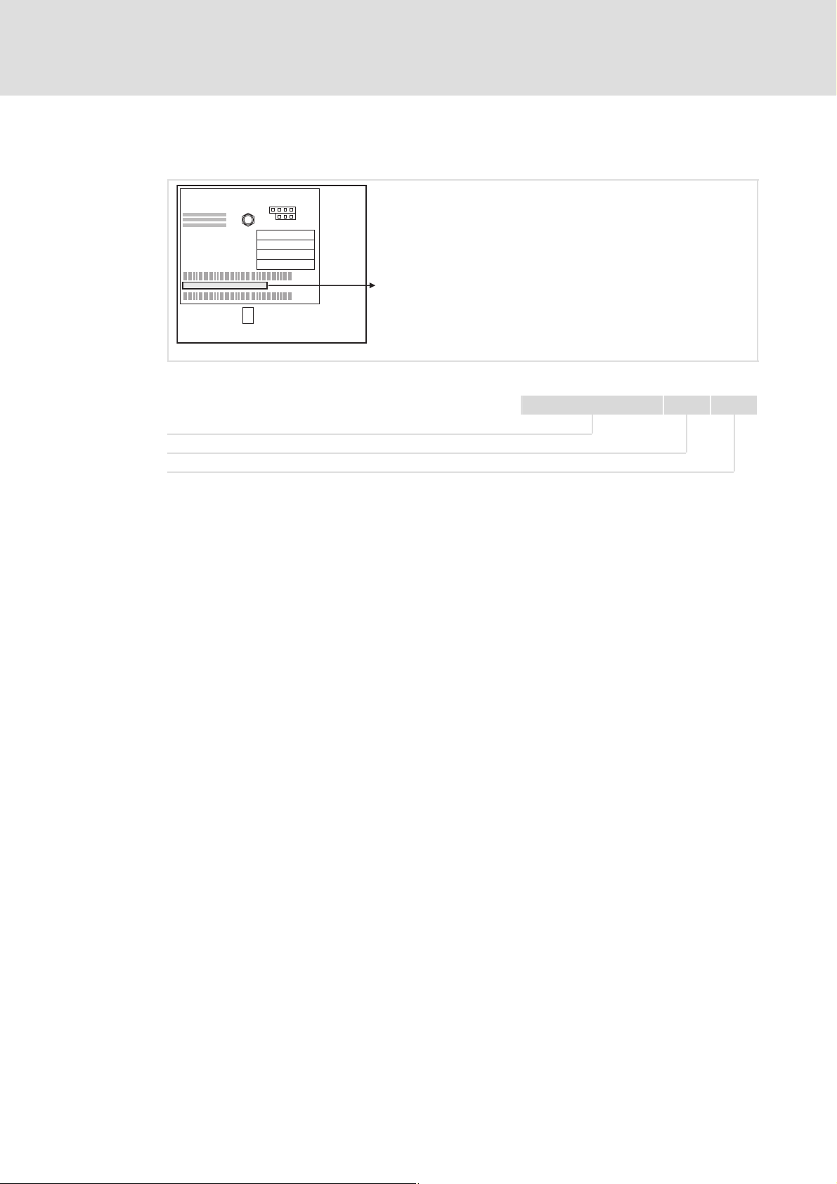
3.3 Product features
ƒ Attachable communication module for the basic Lenze devices 8200 vector, 93XX,
9300 Servo PLC, Drive PLC, ECSXX
ƒ Front DIP switches for setting the ...
– CAN node address (max. 127 nodes)
– baud rate (10, 20, 50, 125, 250, 500 and 1000 kbit/s)
ƒ Bus expansion without repeater up to 7450 m
ƒ Topology: Line terminated at both ends (R = 120 W)
ƒ Simple connection through plug−on screw terminals
ƒ Together with a 9300 Servo PLC, additional CANopen application profiles can be
implemented.
Product description
Product features
3
EDSMF2178IB EN 3.0
l
15
Page 16
3
Product description
Connections and interfaces
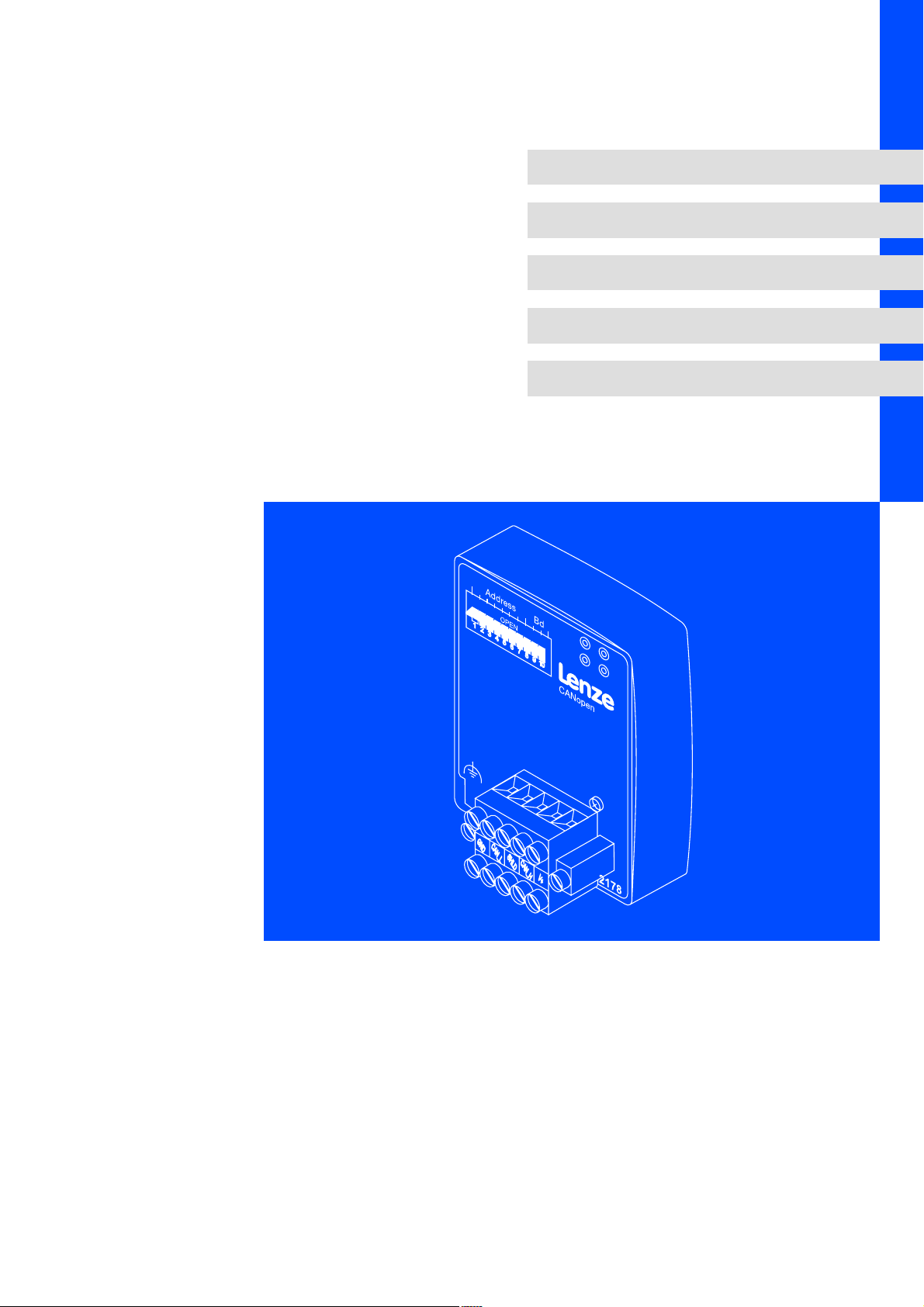
3.4 Connections and interfaces
EMF2178IB
6
5
Address Bd
GND
CAN_L
0
L
CANopen
CAN_H
SHLD
1
2
3
V+
4
2178
2178CAN003
Legend for fold−out page
Pos. Description Detailed
0 Connection status to standard device (two−colour LED)
1 Connection status to fieldbus (two−colour LED)
2 Operating status of standard device (green and red Drive LED)
3 Fixing screw
4 Plug connector with double screw connection, 5−pole ^ 24
5 PE shield cable connection
6 DIP switches for setting the
l node address (switches 1 ... 7)
l baud rate (switches 8 ... 10)
8 Nameplate ^ 14
information
^ 89
^ 33
2102LEC007
16
l
EDSMF2178IB EN 3.0
Page 17

General data and operating conditions
4 Technical data
4.1 General data and operating conditions
Field Values
Order designation EMF2178IB
Communication media DIN ISO 11898
Network topology Line terminated at both ends (R = 120 W)
Communication profile CANopen, DS301 V4.01
Node addresses Max. 127
Cable length Max. 7450 m (depending on the baud rate, ^ 27)
Baud rate [kbit/s] 10, 20, 50, 125, 250, 500, 1000
Voltage supply
Internal or external supply possible for basic devices: 8200 vector / 93XX /
9300 Servo PLC / Drive PLC / ECSXX
(also see ^ 30)
External supply via separate power supply unit:
V+: V = 24 V DC ± 10 %
I = 100 mA
GND:
Reference potential for external voltage supply
Technical data
4
, Documentation for Lenze series of devices 8200 vector, 9300 and ECS
Here you can find the ambient conditions and the electromagnetic
compatibility (EMC) specifications applying to the communication module.
EDSMF2178IB EN 3.0
l
17
Page 18

4
Technical data
Protective insulation
4.2 Protective insulation
{ Danger!
Dangerous electrical voltage
If Lenze controllers are used on a phase earthed mains with a rated mains
voltage ³ 400 V, protection against accidental contact is not ensured without
implementing external measures.
Possible consequences:
ƒ Death or serious injury
Protective measures:
ƒ If protection against accidental contact is required for the control terminals
of the controller and the connections of the plugged device modules, ...
– a double isolating distance must exist.
– the components to be connected must be provided with the second
isolating distance.
Protective insulation between the bus and ... Type of insulation according to EN 61800−5−1
Reference earth / PE Functional insulation
External supply No functional insulation
Power section
l 8200 vector Double insulation
l 9300 vector, Servo PLC Double insulation
l Drive PLC Double insulation
l ECSXX Double insulation
Control terminals
l 8200 vector
(with internal supply, ^ 30)
l 8200 vector
(with external supply, ^ 30)
l 9300 vector, Servo PLC Basic insulation
l Drive PLC Basic insulation
l ECSXX Basic insulation
No functional insulation
Basic insulation
18
l
EDSMF2178IB EN 3.0
Page 19

4.3 Communication time
The communication time is the time between the start of a request and the arrival of the
corresponding response.
The CAN bus communication times depend on ...
ƒ the processing time in the controller (see documentation of the controller)
ƒ Telegram runtime
– baud rate
– telegram length
ƒ the data priority
ƒ the bus load
Processing time in the controller
Technical data
Communication time
4
, Documentation for the controller
Here you can find information on the processing times in the controller.
Telegram time
The telegram times depend on the baud rate and the telegram length:
Baud rate
[kbit/s]
0 bytes 2 bytes 8 bytes
10 5.44 7.36 13.12
20 2.72 3.68 6.56
50 1.09 1.47 2.62
125 0.44 0.59 1.05
250 0.22 0.29 0.52
500 0.11 0.15 0.26
1000 0.05 0.07 0.13
Telegram runtime
[ms]
EDSMF2178IB EN 3.0
l
19
Page 20
4
Technical data
Dimensions
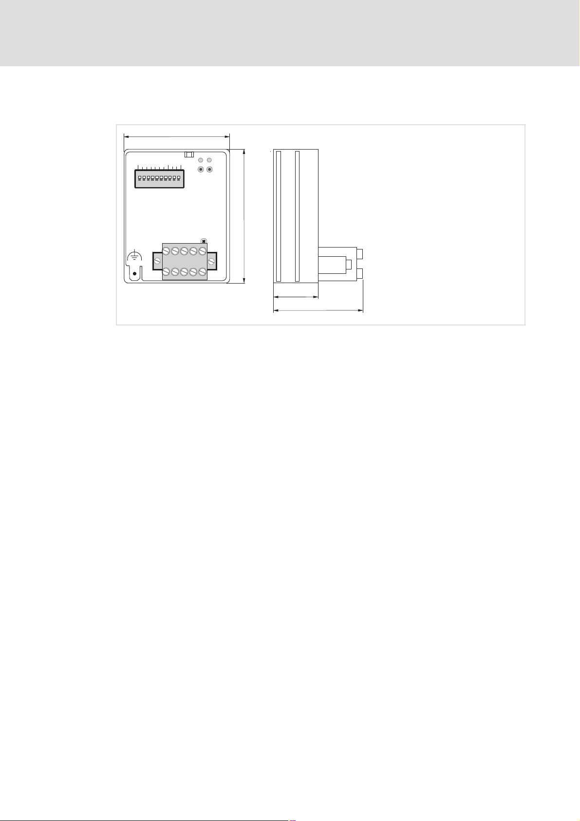
4.4 Dimensions
Address Bd
GND
Fig. 4−1 Dimensions of the communication module (all dimensions in mm)
62
CAN_L
L
CANopen
CAN_H
SHLD
75
V+
2178
18
36
2178CAN003
20
l
EDSMF2178IB EN 3.0
Page 21

5 Installation
} Danger!
Inappropriate handling of the communication module and the standard device
can cause serious personal injury and material damage.
Observe the safety instructions and residual hazards described in the
documentation for the standard device.
( Stop!
The device contains components that can be destroyed by electrostatic
discharge!
Before working on the device, the personnel must ensure that they are free of
electrostatic charge by using appropriate measures.
Installation 5
EDSMF2178IB EN 3.0
l
21
Page 22
5
5.1 Mechanical installation
Installation
Mechanical installation
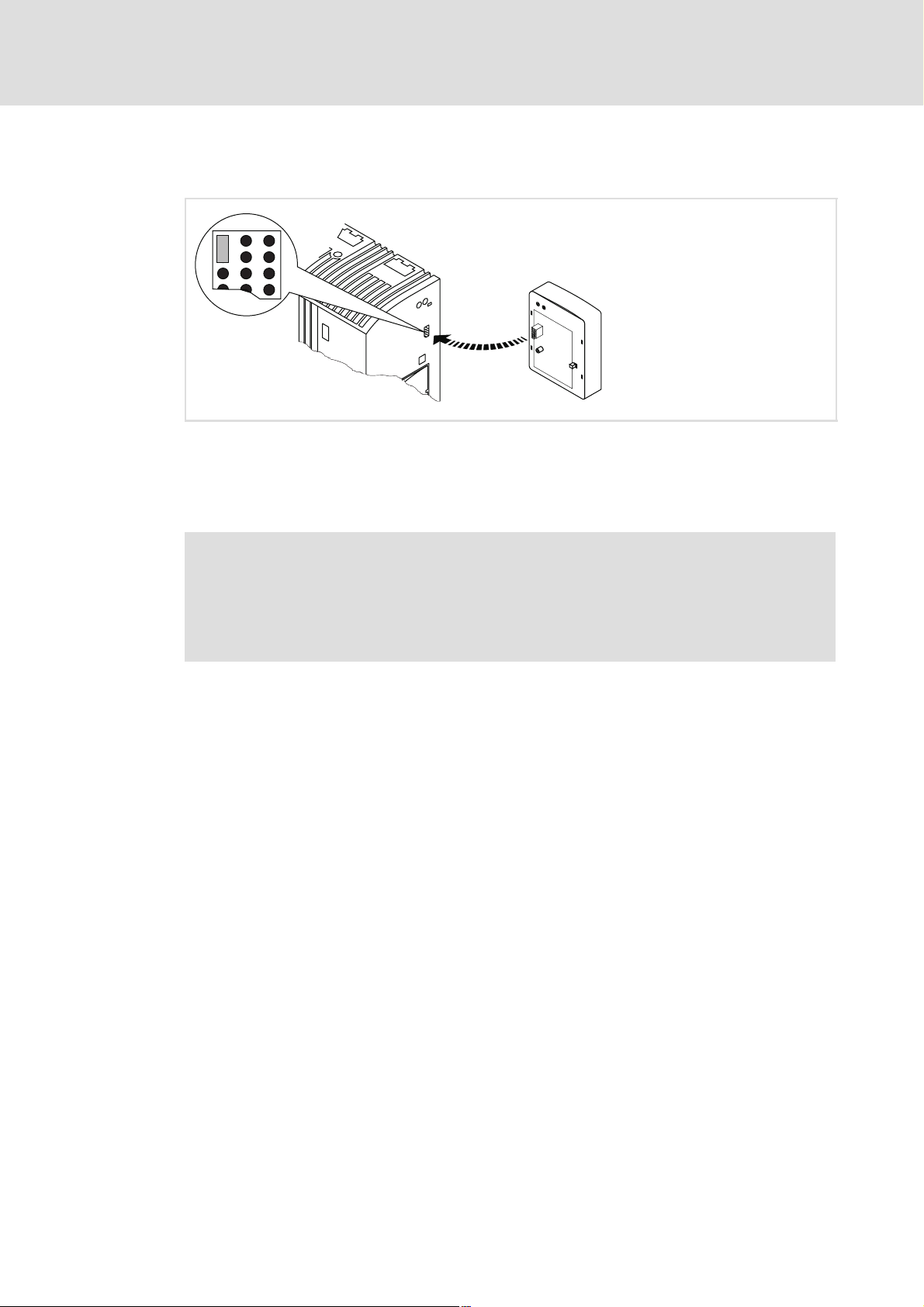
Fig. 5−1 Attaching the communication module
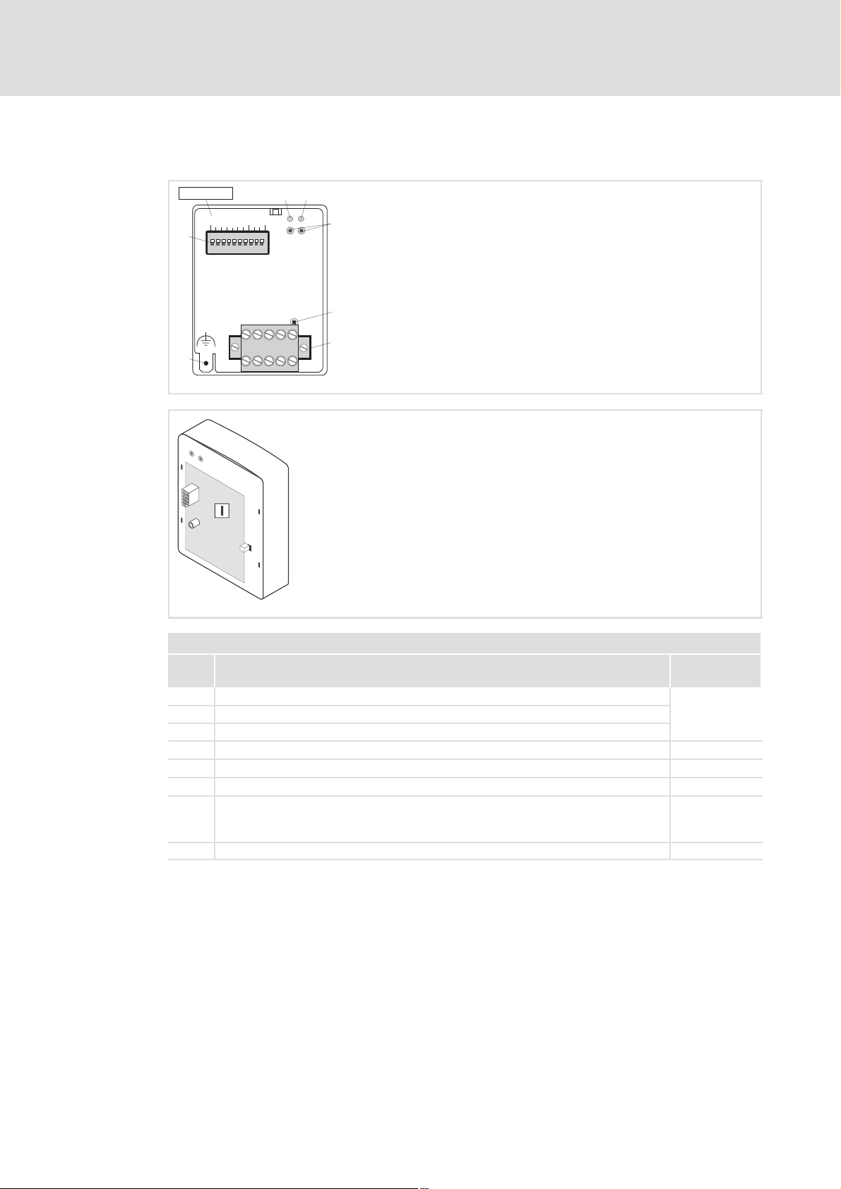
ƒ Plug the communication module onto the standard device (here: 8200 vector).
ƒ Tighten the communication module to the standard device using the fixing screw in
order to ensure a good PE connection.
2102LEC014
) Note!
For the internal supply of the communication module by the 8200 vector
frequency inverter the jumper has to be adjusted within the interface opening
(see illustration above).
Observe the notes (¶ 30).
22
l
EDSMF2178IB EN 3.0
Page 23

Wiring according to EMC (CE−typical drive system)
5.2 Electrical installation
5.2.1 Wiring according to EMC (CE−typical drive system)
For wiring according to EMC requirements observe the following points:
) Note!
ƒ Separate control cables/data lines from motor cables.
ƒ Connect the shields of control cables/data lines at both ends in the case of
digital signals.
ƒ Use an equalizing conductor with a cross−section of at least 16mm
(reference:PE) to avoid potential differences between the bus nodes.
ƒ Observe the other notes concerning EMC−compliant wiring given in the
documentation for the standard device.
Procedure for wiring
Installation
Electrical installation
5
2
1. Observe the bus topology, i.e. do not use stubs.
2. Observe notes and wiring instructions in the documents for the control system.
3. Only use cables corresponding to the listed specifications (¶ 26).
4. Observe the permissible bus cable length (¶ 27)
5. Connect bus terminating resistors of 120 W each (scope of supply):
– only to the physically first and last node
– between the terminals CAN−LOW and CAN−HIGH
.
EDSMF2178IB EN 3.0
l
23
Page 24
5
Installation
Electrical installation
Wiring with a host (master)
5.2.2 Wiring with a host (master)
{ Danger!
An additional electrical isolation is required if a safe electrical isolation
(reinforced insulation) to EN61800−5−1 is necessary.
For this purpose for instance an interface module for the master computer with an
additional electrical isolation can be used (see respective manufacturer information).
For wiring observe the electrical isolation of the supply voltage. The supply voltage is on the
same potential as the data bus.
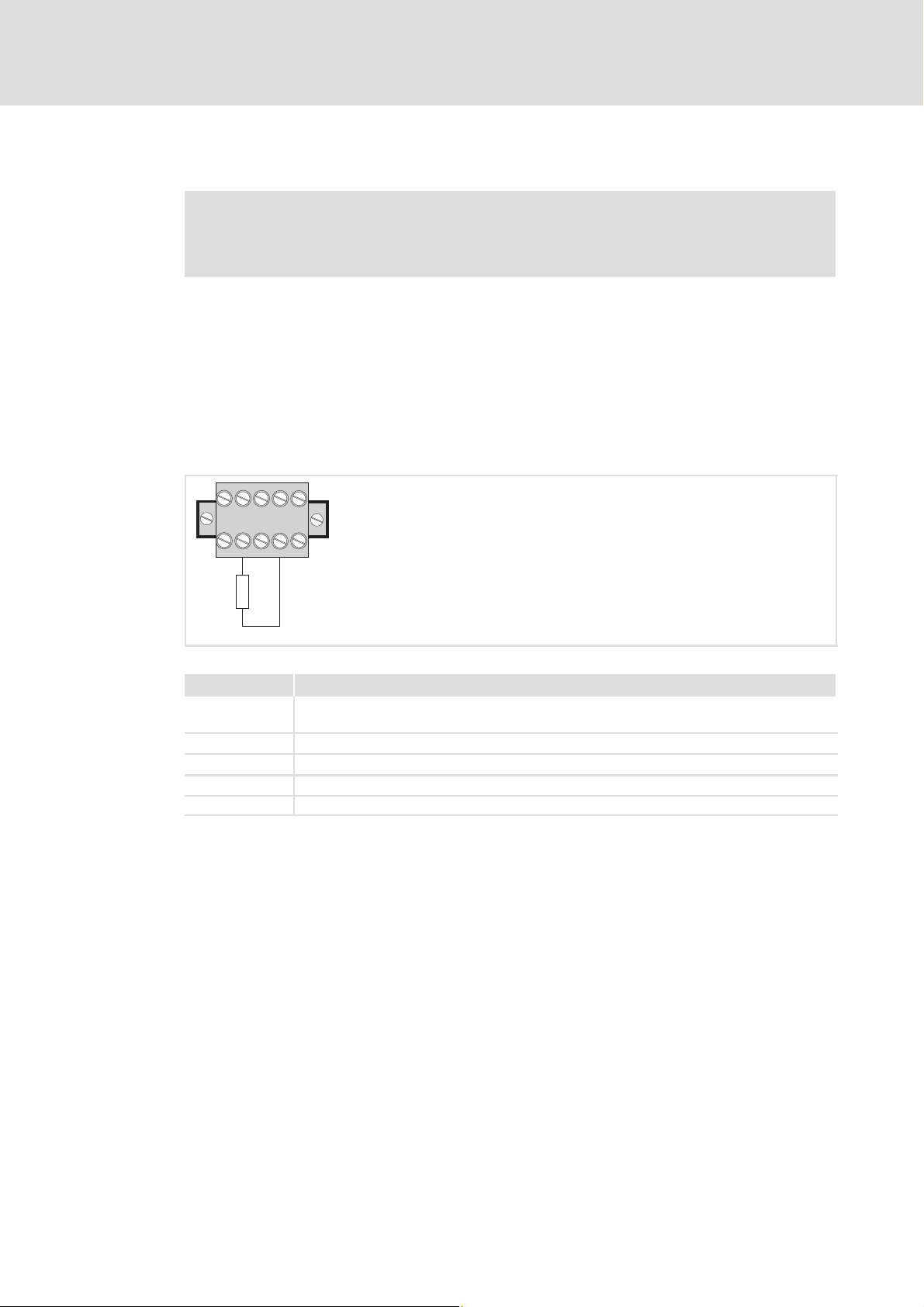
The 5−pole plug connector with double screw connection serves to
ƒ connect the bus (¶ 25);
ƒ effect the external voltage supply (¶ 30).
CAN_H
CAN_L
SHLD
GND
120W
V+
2178CAN003
Fig. 5−2 5−pole plug connector with double screw connection
Designation Explanation
GND Reference potential for external voltage supply
CAN−GND connection
CAN_L Data line / input for terminating resistor 120 W
SHIELD Shielding
CAN_H Data line / input for terminating resistor 120 W
V+ External voltage supply
24
l
EDSMF2178IB EN 3.0
Page 25

Installation
Electrical installation
Wiring system bus (CAN)
5
5.2.3 Wiring system bus (CAN)
Structure of a CAN bus system (example)
The CAN bus system is designed as a 2 conductor (twisted pair) shielded with additional
mass and termination at both ends of the line.
For sending and receiving data the following paths are available:
ƒ Max. three process data channels (PDO = Process Data Object)
– Process data are sent via the process data channel and are used for high−speed and
high−priority control tasks. Typical process data are, for instance, control words,
status words, setpoints and actual values of a standard device.
ƒ Two parameter data channels (SDO = Service Data Object)
– The parameters are transferred at lower priority than the process data and are set
or changed e.g. during commissioning or product change.
– The parameters are accessed via the parameter data channels of the EMF2178IB
communication module to the codes of the basic Lenze device or the
corresponding CANopen objects.
– With both parameter data channels, two masters can be connected to a standard
device. A PC (e.g. with the Lenze software "Global Drive Control") or an operator
terminal serve to change parameters directly at the standard device during
operation of a system connected to PLC. The second parameter data channel can
be reached under the set address (via DIP switch or C0009) with an offset of "64".
If, e.g., a PLC addresses the standard device with the address "1" and a second
commanding device the address "65", always the same standard device is
addressed.
– The second parameter channel is deactivated in the default state.
) Note!
ƒ The last telegram determines the parameter when a parameter is accessed
by two units (see CANopen objects 1200 and 1201 "Server SDO
Parameters".(¶ 107)).
ƒ Please observe the notes in the chapter 6Commissioning (¶ 33), if you do
not select the baud rate and address via the front DIP switches.
EDSMF2178IB EN 3.0
l
25
Page 26
5
Installation
Electrical installation
Specification of the transmission cable
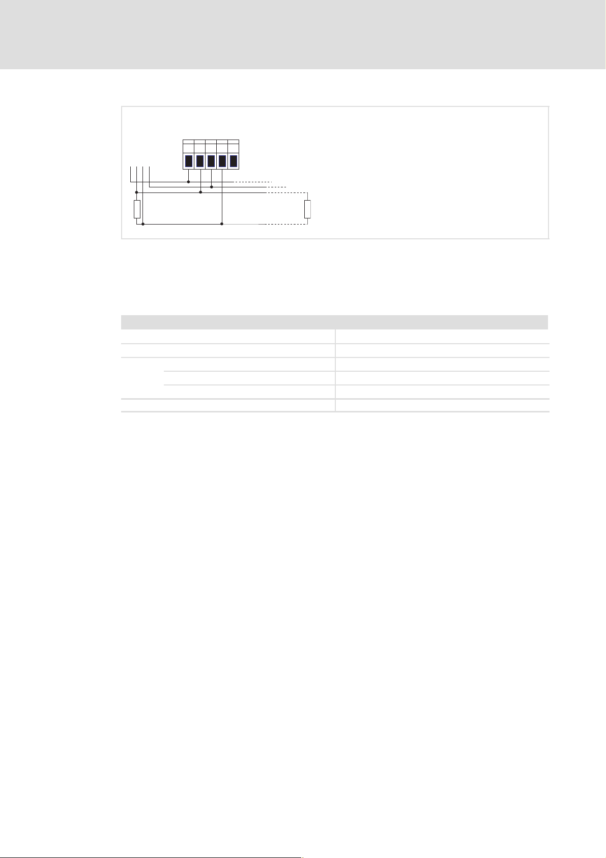
V+
SHLD
CAN_L
CAN
GND
LOW
+
HIGH
GND
CAN_H
EMF2178IB
GND
+
120 W
Fig. 5−3 Connection to the plug connector
5.2.4 Specification of the transmission cable
We recommend the use of CAN cables in accordance with ISO 11898−2:
CAN cable in accordance with ISO 11898−2
Cable type Paired with shielding
Impedance 120 W (95 ... 140 W)
Cable resistance/cross−section
Cable length £ 300 m £ 70 mW/m / 0.25 0.34 mm2 (AWG22)
Cable length 301 1000 m £ 40 mW/m / 0.5 mm2 (AWG20)
Signal propagation delay £ 5 ns/m
120 W
2178CAN002
26
l
EDSMF2178IB EN 3.0
Page 27

Installation
Electrical installation
Bus cable length
5
5.2.5 Bus cable length
) Note!
ƒ It is absolutely necessary to comply with the permissible cable lengths.
ƒ If the total cable lengths of the CAN nodes differ for the same baud rate, the
smaller value must be used to determine the max. cable length.
ƒ Observe the reduction of the total cable length due to the signal delay of the
repeater.
5.2.5.1 Total cable length
The baud rate determines the total cable length.
Baud rate [kbps] Max. bus length [m]
10 7450
20 3950
50 1550
125 630
250 290
500 120
1000 25
Tab. 5−1 Total cable length
EDSMF2178IB EN 3.0
l
27
Page 28

5
Installation
Electrical installation
Bus cable length
5.2.5.2 Segment cable length
The segment cable length is determined by the cable cross−section used and by the number
of nodes. Repeaters divide the total cable length into segments. If no repeaters are used,
the segment cable length is identical to the total cable length.
Max. number of
nodes per segment
2 240 m 430 m 650 m 940 m
5 230 m 420 m 640 m 920 m
10 230 m 410 m 620 m 900 m
20 210 m 390 m 580 m 850 m
32 200 m 360 m 550 m 800 m
63 170 m 310 m 470 m 690 m
100 150 m 270 m 410 m 600 m
Tab. 5−2 Segment cable length
Cable cross−section
(can be interpolated)
0.25 mm
(AWG24)
2
0.5 mm
(AWG21)
2
0.75 mm
(AWG19)
2
1.0 mm
(AWG18)
Example: Selection help
Given
Total cable length to be implemented 200 m
Number of nodes 63
Results
Max. possible baud rate 250 kbps
(derived from Tab. 5−1 Total cable length)
Required cable cross−section (interpolated) 0.30 mm2 (AWG23)
(derived from Tab. 5−2 Segment cable length)
Cable cross−section of standard CAN cable 0.34 mm2 (AWG22)
(see specification of the transmission cable ^ 26)
2
28
l
EDSMF2178IB EN 3.0
Page 29

5.2.5.3 Checking the use of repeaters
Compare the values derived from Tab. 5−1 Total cable length (¶ 27) and Tab. 5−2 Segment
cable length (¶ 28).
ƒ If the sum of the segment cable lengths is smaller than the total cable length to be
implemented, either repeaters must be used or the cable cross−section must be
increased.
ƒ If the use of repeaters reduces the max. possible total cable length so much that it is
smaller than the total cable length to be implemented, then the cable cross−section
must be increased or less repeaters must be used or the baud rate must be
decreased.
ƒ The use of a further repeater is recommended as ...
– service interface
Advantage: Trouble−free connection during bus operation is possible.
– calibration interface
Advantage: The calibration/programming unit remains electrically isolated.
Installation
Electrical installation
Bus cable length
5
Example
Given
Total cable length to be implemented 450 m
Number of nodes 32
Cable cross−section 0.50 mm2 (AWG 20)
Baud rate 125 kbps
Repeater used Lenze repeater EMF2176IB
Reduction of the max. total cable length per
repeater (EMF2176IB)
Results
Max. total cable length 630 m
Max. segment cable length 360 m
Comparison The max. segment cable length is smaller than the total cable
Conclusion A repeater must be installed at the determined max. segment
Results with 1 repeater
Max. total cable length 600 m
Max. segment cable length 720 m
Comparison Both the possible total cable length and the segment cable lengths
Conclusion 1 repeater is sufficient to implement the total cable length of 450
30 m
(see Tab. 5−1 Total cable length (^ 27))
(see Tab. 5−2 Segment cable length (^ 28))
length to be implemented.
cable length of 360 m.
(Reduction of the total cable length (^ 27) by 30 m)
are larger than the total cable length to be implemented.
m.
EDSMF2178IB EN 3.0
l
29
Page 30
5
Installation
Electrical installation
Voltage supply
5.2.6 Voltage supply
Internal voltage supply
) Note!
Internal voltage supply has been selected in the case of standard devices with
an extended AIF interface opening (e.g. front of 8200 vector). The area shown
on a grey background in the graphic marks the jumper position.
ƒ By default, this is not supplied internally in the standard device.
ƒ For internal voltage supply place the jumper on the position indicated
below.
In the case of all other device series (9300, ECS), voltage is always supplied
from the standard device.
(Only external voltage supply possible.)
Lenze setting
Internal voltage supply
External voltage supply
) Note!
In the case of an external voltage supply and for greater distances between
the control cabinets, always use a separate power supply unit (SELV/PELV) that
is safely separated in accordance with EN 61800−5−1 in each control cabinet.
The external voltage supply of the communication module ...
ƒ is required if communication via the fieldbus is to be continued in case the supply of
the standard device fails.
ƒ is carried out via the 2−pole plug connector with screw connection (24 V DC):
Terminal Description
V+ External voltage supply
V = 24VDC±10%
I = 100 mA
GND Reference potential for external voltage supply
ƒ The parameters of a basic device disconnected from the mains cannot be accessed.
30
l
EDSMF2178IB EN 3.0
Page 31

Electrical installation
Terminal data
Area Values
Electrical connection Plug connector with screw connection
Possible connections
Tightening torque 0.5 ... 0.6 Nm (4.4 ... 5.3 lb−in)
Stripping length 6 mm
rigid:
flexible:
2
1.5 mm
without wire end ferrule
1.5 mm
with wire end ferrule, without plastic sleeve
1.5 mm
with wire end ferrule, with plastic sleeve
1.5 mm
(AWG 16)
2
(AWG 16)
2
(AWG 16)
2
(AWG 16)
Installation
Voltage supply
5
EDSMF2178IB EN 3.0
l
31
Page 32

6
Commissioning
Before switching on
6 Commissioning
During commissioning, system−dependent data as e.g. motor parameters, operating
parameters, responses and parameters for fieldbus communication are selected for the
controller.
In Lenze devices, this is done via codes. The codes are stored in numerically ascending order
in the Lenze controllers and in the plugged−in communication/function modules.
In addition to these configuration codes, there are codes for diagnosing and monitoring
the bus devices.
6.1 Before switching on
( Stop!
Before you switch on the standard device with the communication module for
the first time, check
ƒ the entire wiring with regard to completeness, short circuit, and earth fault.
ƒ whether the bus system is terminated by a bus terminating resistor at the
physically first and last node.
6.2 Installing EDS files
The EDS files serve to implement the Lenze communication modules for the AIF and FIF
interfaces into the CANopen configuration software.
The single EDS files describe the implemented CANopen functions of the respective
communication module and the "on board" Lenze system bus (CAN).
I Tip!
The current EDS file required for configuring the EMF2178IB (CANopen)
communication module can be found in the download area on:
www.Lenze.com
32
l
EDSMF2178IB EN 3.0
Page 33

6.3 Setting node address and baud rate
The node address and the baud rate can be set via codes or via the DIP switches arranged
at the front:
ƒ Node address: Switches 1 ... 7 / code C1850/C2350
ƒ Baud rate: Switches 8 ... 10 / code C1851/C2351
The Lenze setting of all DIP switches is OFF.
) Note!
Settings via codes
ƒ In the Lenze setting ˘ Address switches 1 ... 7 = OFF ˘, the values are
accepted from the codes C1850/C2350 (node address) and C1851/C2351
(baud rate).
– Node addresses > 99 can only be set via DIP switch.
– The baud rates 10 kbps and 20 kbps can only be selected via DIP switch.
ƒ Writing the codes (e.g. with GDC via CAN) has a direct effect on the standard
device codes C0009 and C0126.
ƒ Acceptance of code changes by:
– Switching off and then on again the voltage supply;
– "Reset node" with C0358 = 1;
– Network management command "Reset Communication";
– Set C2120 (AIF control byte) = 1.
ƒ The codes are inactive if at least one address switch (1 ... 7) has been set to
ON position before a renewed mains connection.
Commissioning
Setting node address and baud rate
6
EDSMF2178IB EN 3.0
l
33
Page 34

6
Commissioning
Setting node address and baud rate
Node address setting
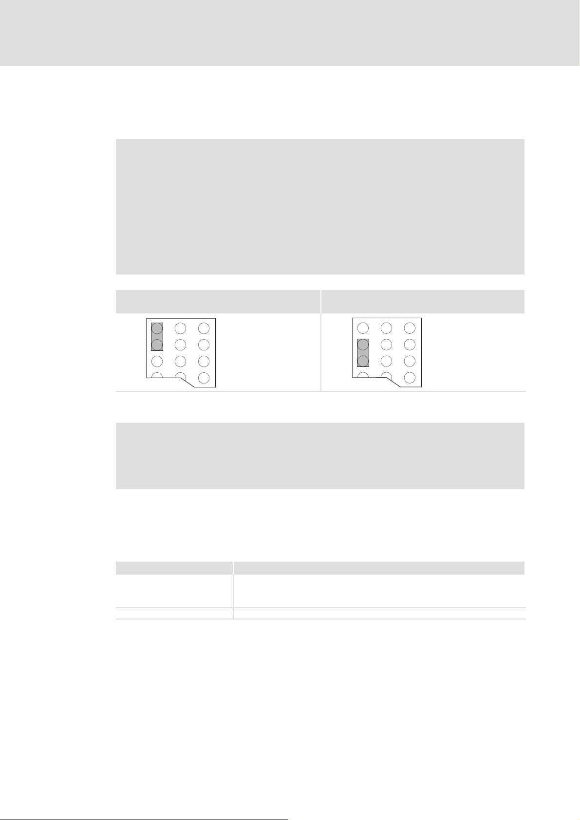
BdAddress
OPEN
OFF
ON
12345678910
Fig. 6−1 Address assignment via DIP switch
ƒ If several devices are connected to the CAN network, the node addresses must differ
from each other.
ƒ The desired node address results from the sum of the values of switches (1 ... 7) in
ON position.
Example
Switch Value
164OFF
2 32 OFF
3 16 ON
4 8 OFF
5 4 ON
6 2 ON
7 1 ON
Switch position Node address
16 + 4 + 2 + 1 = 23
) Note!
Switch off the voltage supply of the communication module, and then switch
it on again to activate the changed settings.
34
l
EDSMF2178IB EN 3.0
Page 35

Setting node address and baud rate
Baud rate setting
BdAddress
OPEN
OFF
ON
12345678910
Fig. 6−2 Baud rate setting
ƒ The baud rate must be the same for all CAN nodes.
ƒ The following baud rates can be set:
Commissioning
6
Baud rate [kbps]
8 9 10
10 ON ON OFF
20 ON OFF ON
50 OFF ON ON
125 OFF ON OFF
250 OFF OFF ON
500 OFF OFF OFF
1000 ON OFF OFF
Switch
) Note!
Switch off the voltage supply of the communication module, and then switch
it on again to activate the changed settings.
EDSMF2178IB EN 3.0
l
35
Page 36

6
6.4 Initial switch−on
Commissioning
Initial switch−on
) Note!
Do not change the setting sequence.
1. Switch on the standard device and, if necessary, the external voltage supply of the
communication module.
– The green LED 0 on the front of the communication module is lit.
– The status LED of the standard device (Drive LED) 2 must be lit or blinking. The
meaning of the signalling can be found in the standard device documentation.
2. You can now communicate with the drive, i. e.
– all parameters (SDO) can be read;
– all writable parameters (SDO) can be overwritten.
3. After a state change ("Operational") process data can be exchanged with the drive.
2172CAN000D
Fig. 6−3 LEDs of the communication module
36
l
EDSMF2178IB EN 3.0
Page 37

Enable drive via the communication module
6.5 Enable drive via the communication module
) Note!
ƒ During operation, the plugging of the communication module onto a
different controller may cause undefined operating states.
ƒ Observe the information on the CAN configuration and controller enable in
the documentation of the corresponding controller.
Enable the 8200 vector via the communication module
Step Procedure Comments
1. Set C0001 from
"0" to "3"
2. Assign 28 to HIGH level The terminal 28 (controller enable) is always active and must be assigned to
3. Assign input terminal
for QSP to HIGH level
4. The controller now accepts parameter data and process data.
Enable 93XX via the communication module
The Lenze parameter C0001 (operating mode) can be set with the GDC,
keypad XT or directly via CANopen.
Example for direct setting via CANopen:
Write (C0001 = 3)
l Index = 0x5FFE (resulting from: 0x5FFF − (C0001)
l Subindex: 0
l Value: 30000 (resulting from: C0001 = 3 x 10000)
HIGH level during CANopen operation. Otherwise the controller cannot be
enabled via CANopen.
The quick stop function (QSP) is always active. If QSP is configured to an
input terminal (Lenze setting: Not assigned), it must be assigned to HIGH
level during CANopen operation.
Commissioning
;)
hex
6
Step Procedure Comments
1. Set C0005 to th value
"xxx3"
2. Set C0142 = 0 See "Protection against uncontrolled restart" (^ 38).
3. Assign 28 to HIGH level The terminal 28 (controller enable) is always active and must be assigned to
4. Assign terminal E1 to
HIGH level
5. Connect terminal X5/A1
to
l X5/28 and
l X5/E1
6. The controller now accepts parameter data and process data.
The value "xxx3" of the Lenze parameter C0005 (control of the controller via
CANopen) can be set with the GDC, keypad XT or directly via CANopen.
Example for the first commissioning with the signal configuration "1013":
Write (C0005 = 1013)
l Index = 0x5FFA (resulting from: 0x5FFF − (C0005)
l Subindex: 0
l Value: 10130000 (resulting from: C0005 = 1013 x 10000)
HIGH level during CANopen operation. Otherwise the controller cannot be
enabled via CANopen.
If the signal configuration C0005 = 1013, the quick stop function (QSP) is
assigned to the digital input terminals E1 and E2 in connection with the
right/left change−over and thus always active.
Only affects the signal configuration C0005 = xx13
With this signal configuration the terminal A1 is switched as voltage
output.
hex
)
EDSMF2178IB EN 3.0
l
37
Page 38

6
Commissioning
Enable drive via the communication module
Enable ECSXX via the communication module
Step Procedure Comments
1. Select control interface
"AIF" via code.
2. Set C0142 = 0 See "Protection against uncontrolled restart" (^ 38).
3. Assign terminals X6/SI1
and X6/SI2 to HIGH
level
4. The controller now accepts parameter data and process data.
See documentation of the corresponding ECS controller.
The terminals X6/SI1 (controller enable/inhibit) and X6/SI2 (pulse
enable/inhibit) are always active and must be assigned to HIGH level during
CANopen operation. Otherwise, the controller cannot be enabled via
CANopen.
Protection against uncontrolled restart
) Note!
Establishing communication
If communication is to be established via an externally supplied
communication module, initially the standard device must also be switched
on.
After communication has been established, the externally supplied module is
independent of the power on/off state of the standard device.
Protection against uncontrolled restart
After a fault (e.g. short−term mains failure), a restart of the drive is not always
wanted and − in some cases − even not allowed.
The restart behaviour of the controller can be set in C0142:
ƒ C0142 = 0 (Lenze setting)
– The controller remains inhibited (even if the fault is no longer active).
– The drive starts up in a controlled manner by explicit controller enable:
93XX: Set terminal 28 to HIGH level.
ECSXX: Set terminals X6/SI1 and X6/SI2 to HIGH level.
ƒ C0142 = 1
– An uncontrolled restart of the drive is possible.
38
l
EDSMF2178IB EN 3.0
Page 39

Replacing the EMF2172IB communication module (CAN) 7
7 Replacing the EMF2172IB communication module (CAN)
Observe the following information when replacing the EMF2172IB (CAN) communication
module by EMF2178IB (CANopen):
ƒ The communication modules feature different plug connectors for connecting the
voltage supply and the system bus (CAN).
ƒ The DIP switches of the communication modules feature different assignments for
setting the CAN node address and the baud rate (¶ 40). Furthermore there are
different adjustable CAN address ranges:
Communication module CAN address range DIP switch
EMF2172IB (CAN) 1 ... 63 S4 ... S9
EMF2178IB (CANopen) 1 ... 127 S1 ... S7
ƒ Depending on the standard device used, the 2. SDO channel is activated via code
C1865/1 or C2365/1 (¶ 41).
Changing the wiring
The following illustration shows how you must carry out the previous wiring for the
EMF2178IB communication module now.
Address Bd
1 - 3
4 - 9
addressbaud
24 V DC
+
-
21
L
CAN
Low
GND
5
4
3
High
2172
6
L
CANopen
CAN_H
CAN_L
SHLD
GND
2
4
V+
2178
1
3
5
6
2178CAN010
EDSMF2178IB EN 3.0
l
39
Page 40

Replacing the EMF2172IB communication module (CAN)7
DIP switch settings
) Note!
On the EMF2178IB communication module, the switch S1 = OFF(Lenze setting)
must remain set. (An address setting > 63 was not possible for EMF2172IB.)
L
1 - 3
ON
OFF
CAN
4 - 9
addressbaud
OFF
ON
Address
- -WS1 = OFF
S9 S2
W
S4 S7
W
Baudrate
S3 S8
W
S1 S10
W
Address Bd
1
78
10
L
CANopen
2178CAN011
Switch Value
Example
EMF2172IB EMF2178IB Switch position CAN node address
−S164 OFF
S9 S2 32 OFF
S8 S3 16 ON
S7 S4 8 OFF
16 + 4 + 2 + 1 = 23
S6 S5 4 ON
S5 S6 2 ON
S4 S7 1 ON
40
l
EDSMF2178IB EN 3.0
Page 41

Replacing the EMF2172IB communication module (CAN) 7
Activate the 2. SDO channel
Depending on the standard device used, set code C1865/1 or C2365/1 to activate the
2. SDO channel.
Settings via the GDC/XT keypad for these standard devices:
EVS 93xx−ES
EVS 93xx−EP
EVS 93xx−EK
EVS 93xx−ER
EVF 93xx−EV
E82EVxxx
1. Plug the EMF2178IB communication module onto
the standard device.
2. Use the GDC to set code C1865/1 = 1.
The setting is saved with mains failure protection
directly in the communication module.
When using the standard devices specified above,
the setting can also be carried out beforehand.
EVS 93xx−EI
EVS 93xx−ET
EPL−10200
ECSxS/P/M/A
Use the GDC or XT keypad to set standard device code
C2365/1 = 1 and save it with mains failure protection.
After mains connection of one of the standard devices
specified above, or after plugging on the EMF2178IB
communication module, the contents of C2365 are
written to the communication module.
EDSMF2178IB EN 3.0
l
41
Page 42

8
Data transfer
Structure of the CAN telegram
8 Data transfer
Master and controller communicate with each other by exchanging data telegrams via the
CAN bus.
The user data area of the CAN telegram either contains network management data, process
dataor parameter data (^ 44).
Different communication channels are assigned to parameter and process data in the
controller:
ƒ Process data are transferred via the process data channel.
ƒ Parameter data are transferred via the parameter data channel.
8.1 Structure of the CAN telegram
Control field CRC delimit. ACK delimit.
Start RTR bit CRC sequence ACK slot End
Identifier User data (0 ... 8 bytes)
l Network management
1 bit 11 bits 1 bit 6 bits 15 bits 1 bit 1 bit 1 bit 7 bits
Fig. 8−1 Basic structure of the CAN telegram
l Process data
l Parameter data
I Tip!
The identifier and the user data will be explained in more detail in this
documentation.
The other signals refer to the transfer characteristics of the CAN telegram
which are not described in this documentation.
For more information please refer to the homepage of the CAN user
organisation CiA (CAN in Automation):
http://www.can−cia.org
42
l
EDSMF2178IB EN 3.0
Page 43

Data transfer
Structure of the CAN telegram
Identifier (COB−ID)
The principle of the CAN communication is based on a message−oriented data exchange
between a transmitter and various receivers. Here, all nodes can quasi simultaneously
transmit and receive messages. In case of CANopen, a node orientation is achieved by
having only one transmitter for each message.
The control which node is to receive a transmitted message is executed via the identifierin
the CAN telegram, also called COB−ID(Communication Object Identifier). In addition to the
addressing, the identifier contains information on the priority of the message and the type
of user data.
With the exception of the network management and the sync telegram, the identifier
consists of a basic identifier and the node address of the node to be addressed:
Identifier (COB−ID) = basic identifier + adjustable node address (Node−ID)
The identifier assignment is defined in the CANopen protocol.
Basic identifier
8
The basic identifier is preset as default with the following values according to the CANopen
specification:
Object
NMT 0 0x000
Sync 128 0x080
Emergency X 128 0x080
PDO1
(Process data channel 1)
PDO2
(Process data channel 2)
PDO3
(process data channel 3)
SDO1
(Parameter data channel 1)
SDO2
(parameter data channel 2)
Lenze setting: not active.
Node guarding / heartbeat X 1792 0x700
TPDO1
RPDO1
TPDO2
RPDO2
TPDO3
RPDO3
from the drive to the drive dec hex
Direction Basic identifier
X 384 0x180
X 512 0x200
X 640 0x280
X 768 0x300
X 896 0x380
X 1024 0x400
X 1408 0x580
X 1536 0x600
X 1472 0x5C0
X 1600 0x640
Node address (node ID)
Each node of the CAN network must be assigned with a node address (also called node ID)
within the valid address range for unambiguous identification.
EDSMF2178IB EN 3.0
ƒ A node address must not be assigned more than once within a network.
ƒ The node address of the controller is configured under code C1850/C2350 or via DIP
switch(^ 33).
l
43
Page 44

8
Data transfer
Structure of the CAN telegram
User data
The user data area of the CAN telegram either contains network management data, process
dataor parameter data:
ƒ Network management data (NMT data)
Network management data contain information on the establishment of
communication via the CAN network (^ 45).
ƒ Process data (PDO, Process Data Objects)
– Process data are transferred via the process data channel (see also chapter "Process
data transfer", ^ 48).
– Process data serve to control the controller (slave).
– Process data are transferred between the host and the controllers to ensure a
continuous exchange of current input and output data.
– The host has direct access to process data. In the PLC, the data are, for instance,
directly assigned to the I/O area. An exchange between host and controller is
required as fast as possible. Small amounts of data can be transferred cyclically.
– Process data are not saved in the controller.
– Process data are, for instance, control words, status words, setpoints and actual
values.
ƒ Parameter data (SDO, Service Data Objects)
– Parameter data are transmitted as SDOs via the parameter data channel and
acknowledged by the receiver, i.e.the sender gets a feedback about the
transmission being successful or not (see also chapter "parameter data transfer",
^ 69).
– The parameter data channel enables access to all Lenze codes and CANopen
indices.
– The parameters for instance are set for the initial system set−up during
commissioning or when material is changed on the production machine.
– In general, the parameter data transfer is not time−critical.
– Parameter changes are automatically stored in the controller.
– Parameter data for example are operating parameters, diagnostics information,
and motor data.
44
l
EDSMF2178IB EN 3.0
Page 45

Data transfer
CAN communication phases / network management (NMT)
8.2 CAN communication phases / network management (NMT)
Regarding communication, the controller knows the following statuses:
Status Description
"Initialisation" After the controller is switched on, the initialisation phase is run through.
During this phase, the controller is not involved in the data exchange on the
bus.
A part of the initialisation or the complete initialisation can be run through
again in every NMT status by transmitting different telegrams (see "state
transition"). Here, all parameters are written with their set values.
After completing the initialisation, the controller automatically adopts the
"Pre−Operational" status.
"Pre−Operational" The controller can receive parameter data.
The process data are ignored.
"Operational" The controller can receive parameter data and process data.
"Stopped" Only network management telegrams can be received.
8
EDSMF2178IB EN 3.0
l
45
Page 46

8
Data transfer
CAN communication phases / network management (NMT)
Network management (NMT)
The telegram structure used for the network management contains the identifier and the
command included in the user data which consists of the command byte and the node
address.
Telegrams with the identifier "0" and 2 byte user data are used to change between the
different communication phases.
Identifier User data
Value = 0
11 bits
Fig. 8−2 Telegram for switching over the communication phases
A bus node, the network master, carries out the changes between the communication
phases for the whole network.
With code C1852 / C2352 (¶ 125) you can set up the communication module for master
or slave operation.
After an adjustable boot−up time in C1856/1 / C2356/1 in master operation, (¶ 130) the
NMT command Start_Remote_Node is transmitted, which puts all nodes into the
"Operational" status.
Only contains command
2bytes
) Note!
Only a change to "Operational" status enables communication via the process
data!
Example:
If all nodes connected to the bus are to be switched from the
"Pre−Operational" communication status to the "Operational" communication
status via the CAN master, the identifier and the user data must have the
following values in the transmission telegram:
ƒ Identifier: 0x00 (broadcast telegram)
ƒ User data: 0x0100
46
l
EDSMF2178IB EN 3.0
Page 47

CAN communication phases / network management (NMT)
State transitions
(1)
Initialisation
(2)
(14)
Pre-Operational
(7)
(4)
(13)
(3)
(12)
Operational
Fig. 8−3 State transitions in CAN network (NMT)
(5)
(6)
Stopped
(8)
(11)
(10)
(9)
Data transfer
8
E82ZAFU004
Status
transition
(1) − Initialisation
(2) − Pre−operational
From that moment on, the master changes the states for the whole network. A target address, which is part of
the command, specifies the receiver(s).
(3), (6) 0x01yy Operational
(4), (7) 0x80yy Pre−operational
(5), (8) 0x02yy Stopped Only network management telegrams can be received.
(9)
(10)
(11)
(12)
(13)
(14)
Command
(hex)
0x81yy
0x82yy
Network status after
change
Initialisation
Effects on process and parameter data after the status
change
Initialisation starts automatically when the mains is
switched on.
During initialisation, the drive does not take part in the
data transfer.
After initialisation has been completed, the node sends a
boot−up message with an individual identifier on the
CAN bus and changes automatically to the status
"Pre−operational".
In this phase, the master determines the way in which
the controller takes part in the communication.
Network management telegrams, sync, emergency,
process data (PDOs) and parameter data (SDOs) active
(like "Start remote node")
Optional:
When the status is changed, event and time−controlled
process data (PDOs) will be sent once.
Network management telegrams, sync, emergency and
parameter data (SDOs) active (like "Enter pre−operational
state")
Initialises all parameters in the communication module
with the stored values (corresponds to "Reset node")
Initialises communication−relevant parameters (CIA DS
301) in the communication module with the stored
values (corresponds to "Reset communication")
EDSMF2178IB EN 3.0
yy = 00 In case of this assignment, the telegram addresses all devices connected. The
state of all devices can be changed at the same time.
yy = node ID If a node address is given, only the state of the device with the corresponding
address will be changed.
l
47
Page 48

9
Process data transfer
Available process data objects
9 Process data transfer
Agreements
ƒ Process data telegrams between host (master) and controller (slave) are
distinguished as follows with regard to their direction:
– Process data telegrams to the controller
– Process data telegrams from the controller
ƒ In CANopen, the process data objects are named from the node’s view:
– RPDOx: A process data object received by a node
– TPDOx: A process data object transmitted by a node
9.1 Available process data objects
Depending on the basic device used, up to 3 RPDOs and TPDOs can be available.
I Tip!
From the masters’s view, the following terms are used for process data
transfer with the standard device and the plugged communication module:
ƒ The master sends the process data output words (POWs) as process output
data to the standard device
ƒ The master receives the process data input words (PIWs) as process input
data from the standard device.
48
l
EDSMF2178IB EN 3.0
Page 49

Process data transfer
Available process data objects
Process data telegram to the controller (RPDO)
The identifier of the process data telegram includes the node address of the controller. The
telegram has a maximum user data length of 8 bytes. This chapter describes which user
data will be evaluated for the controllers.
The CAN bus is connected to the automation interface X1 via the communication module.
X1 is connected to the function block AIF−IN. Here, the user data is transformed into
corresponding signal types in order to use them for further function blocks. The control
word is especially important for the controller. It contains the drive setpoint in user data
bytes 1 and 2.
AIF−IN
Control word
Byte 1, 2 =
9
Byte 3, 4
Identifier
Fig. 9−1 Example: Process data telegram to controller
User data
8 bytes
X1 = AIF interface, e.g. 8200 vector
X1
AIF
X1
Process data telegram from the controller (TPDO)
For the cyclic process data telegrams from the controller, the function block to be used is
called AIF−OUT. The status word (bytes 1 and 2) included in the process data telegram is
transmitted on the CAN bus to the master via this function block.
EDSMF2178IB EN 3.0
l
49
Page 50

9
9.2 Configuring process data channel
Process data transfer
Configuring process data channel
Selection of the setpoint source
Drive controller 8200 vector
The selection of the setpoint source for these controllers is determined with code C0001
(index: 0x5FFE). For process data evaluation the code C0001 must be set to 3 when
operating the controller with the communication module.
The setpoint source is the process channel which overwrites the frequency setpoint
(C0046) and the control word (C0135) (see documentation for 8200 vector).
) Note!
Please observe that the setpoint source selection (C0001) must be set equally
in all parameter sets.
Drive controller 93XX
The 9300 controllers do not offer a setpoint source selection which can be set by one code
only. For this purpose, you only need to connect preconfigured function blocks in order to
adapt the controller to the drive task without being an expert in programming.
The user himself is able to carry out the interconnection. However, it is recommended to
use the preconfigurations provided by Lenze, which are saved in the read−only memory of
the controller. The Lenze preconfigurations (code C0005) define which source (terminal,
keyboard, communication module) overwrites the frequency setpoint and the control
word.
For operation via CAN bus, the value to be set under code C0005 must be set to "xxx3" (x =
wildcard for selected preconfiguration).
, 9300 system manual
Here, you can find more detailed information.
PLC devices: 9300 Servo PLC / Drive PLC / ECSxA
For communicating via a communication module (e.g. EMF2178IB), it is necessary that the
system blocks AIF−IN/OUT1 ... 3 and, if required, the AIF management are integrated into
the control configuration of the IEC61131 project.
50
Axis modules of the ECS series
, Operating instructions for the axis modules of the ECS series
Here you can find detailed information on the process data configuration.
l
EDSMF2178IB EN 3.0
Page 51

9.3 Cyclic process data objects
Synchronisation of cyclic process data
The "sync telegram" is used to ensure that the process data can be cyclically read by the
controller and will be accepted by the controller.
The sync telegram is the trigger point for accepting data in the controller and activates the
sending process from the controller. For cyclic process data processing, the sync telegram
must be generated accordingly.
Sync telegram Sync telegram
Process data transfer
Cyclic process data objects
9
Process data from
Controller
Fig. 9−2 Sync telegram
After the sync telegram has been received, the controllers send the cyclic process data to
the master. The master reads them as process input data.
When the sending process has been completed, the controllers receive the process output
data (from the master).
All other telegrams (e. g. parameters or event−controlled process data) are acyclically
accepted by the controllers after transmission has been completed.
Acyclic data have not been taken into account for the above figure. When selecting the
cycle time, they must be considered.
Process data to
Controller
Cycle time
EDSMF2178IB EN 3.0
l
51
Page 52

9
Process data transfer
Cyclic process data objects
Process data signals of Lenze controllers
9.3.1 Process data signals of Lenze controllers
9.3.1.1 Process data signals for 8200 vector frequency inverters
A change of code C0001 to 3 preconfigures the process data words in the controller.
) Note!
Frequency and speed values are normalised with "240005"480Hz.
Process data telegram to drive
User data (up to 8 bytes)
Byte 1 Byte 2 Byte 3 Byte 4 Byte 5 Byte 6 Byte 7 Byte 8
Control
word
Low byte
Byte description:
Byte Content Description
1 C0135
2 C0135
3 AIF−IN.W1, low byte
4 AIF−IN.W1, high byte
5 AIF−IN.W2, low byte
6 AIF−IN.W2, high byte
7 / 8 xx No evaluation of these data, any content possible
Control
word
High byte
Control word, low byte
Control word, high byte
AIF−IN.W1
Low byte
AIF−IN.W1
High byte
Bits 0 ... 7 of the control word under C0135 (^ 145) are entered here.
Bits 8 ... 15 of the control word under C0135 (^ 145) are entered
here.
AIF−IN.Wx is parameterised under code C0412.
AIF−IN.W2
Low byte
AIF−IN.W2
High byte
xx xx
Process data telegram from drive
User data (up to 8 bytes)
Byte 1 Byte 2 Byte 3 Byte 4 Byte 5 Byte 6 Byte 7 Byte 8
Status word
Low byte
Status word
High byte
AIF−OUT.W1
Low byte
AIF−OUT.W1
High byte
AIF−OUT.W2
Low byte
AIF−OUT.W2
High byte
xx xx
Byte description:
Byte Content Explanation
1 C0150
Status word, low byte
2 C0150
Status word, high byte
3 AIF−OUT−W1
Low byte
4 AIF−OUT.W1
High byte
5 AIF−OUT−W2
Low byte
6 AIF−OUT.W2
High byte
7 / 8 xx No evaluation of these data, any content possible
Bits 0 ... 7 of the status word are entered here under C0150 (^ 145).
Bits 8 ... 15 of the status word are entered here under C0150 (^ 145).
AIF−OUT.Wx is parameterised under code C0421.
52
l
EDSMF2178IB EN 3.0
Page 53

Process data transfer
Cyclic process data objects
Process data signals of Lenze controllers
Device control word AIF−CTRL for 8200 vector (C0135, index 0x5F78)
9
Bit
0 / 1 JOG values
2
3
4
5
6
7 DOWN function motor potentiometer
Assignment (Lenze setting)
C0001 = 3 with C0007 £ 51 C0001 = 3 with C0007 > 51
Freely configurable 1
Bit 1 0
0 0 00 = C0046 active
0 1 01 = NSET1−JOG1 (C0037) active
1 0 10 = NSET1−JOG2 (C0038) active
1 1 11 = NSET1−JOG3 (C0039) active
Current direction of rotation (DCTRL1−CW/CCW)
01Not active
Active
Freely configurable 3
Quick stop (QSP) (AIF−CTRL−QSP) Quick stop (QSP) (AIF−CTRL−QSP)
01Not active
Active
Stop ramp function generator (NSET1−RFG1−STOP)
01Not active
Active
Ramp function generator input = 0
(NSET1−RFG1−0)
01Not active
Active
UP function motor potentiometer (MPOT1−UP)
01Not active
Active
01Not active
Active
Freely configurable 5
Freely configurable 6
Freely configurable 7
Freely configurable 8
(MPOT1−DOWN)
Set under
C0410/...
2
4
8 Freely configurable Freely configurable 9
9
10
11 Reset fault
12
13
14
Controller inhibit (AIF−CTRL−CINH) Controller inhibit (AIF−CTRL−CINH)
01Not active
Active
01Not active
Active
External fault (AIF−CTRL−TRIP−SET) External fault (AIF−CTRL−TRIP−SET)
01Not active
Active
01Not active
Active
Reset fault
(AIF−CTRL−TRIP−RESET)
0 −> 1 Edge from 0 to 1 0 −> 1 Edge from 0 to 1
Change over parameter set (DCTRL1−PAR2/4)
01Not active
Active
Change over parameter set (DCTRL1−PAR3/4)
01Not active
Active
DC injection brake (MCTRL1−DCB)
01Not active
Active
(AIF−CTRL−TRIP−RESET)
Freely configurable 13
Freely configurable 14
Freely configurable 15
10
11
12
15 Freely configurable Freely configurable 16
EDSMF2178IB EN 3.0
l
53
Page 54

9
Process data transfer
Cyclic process data objects
Process data signals of Lenze controllers
DCTRL
...
...
...
DCTRL
...
...
...
AIF-IN
AIF-IN.W1
AIF-IN.W2
C0410/x = 10
C0410/x = 11
C0410/x = 12
C0410/x = 22
C0410/x = 25
C0412/x = 10
C0412/x = 11
AIF
AIF-CTRL
16 Bit
16 Bit
16 Bit
.B0
.B1
.B2
.B3
.B4
.B8
.B9
.B10
.B11
.B12
.B15
QSP
...
...
...
CINH
TRIP-SET
TRIP-RESET
...
...
...
Fig. 9−3 System block AIF−IN in 8200 vector (freely configurable assignment)
2141LON011
54
l
EDSMF2178IB EN 3.0
Page 55

Process data transfer
Cyclic process data objects
Process data signals of Lenze controllers
Device status word AIF−STAT for 8200 vector (C0150, index 0x5F69)
Bit Assignment (Lenze setting) Set under C0417/...
0 Current parameter set (DCTRL−PAR−B0) 1
1 Pulse inhibit (DCTRL1−IMP) 2
2 I
3 Output frequency = frequency setpoint (MCTRL1−RFG1=NOUT) 4
4 Ramp function generator input = ramp function generator output 1
5 Q
6 Output frequency = 0 (DCTRL1−NOUT=0) 7
7 Controller inhibit (DCTRL1−CINH) 8
8 ... 11 Device status (DCTRL1−Stat*1 ... STAT*8)
Bit 11 10 9 8
12 Overtemperature warning (DCTRL1−OH−WARN) 13
13 DC−bus overvoltage (DCTRL1−OV) 14
14 Direction of rotation (DCTRL1−CCW) 15
15 Ready for operation (DCTRL1−RDY) 16
limit (MCTRL1−IMAX) 3
max
(NSET1−RFG1−I=0)
threshold (PCTRL1−QMIN) 6
min
0 0 0 0 Device initialisation
0
0 1 0 Switch−on inhibit
0
0 1 1 Operation inhibited
0
1 0 0 Flying restart circuit active
0
1 0 1 DC injection brake active
0
1 1 0 Operation enabled
0
1 1 1 Message active
1
0 0 0 Fault active
1
1 1 1 Communication with basic device not possible
5
Reserved
9
AIF-OUT
AIF-STAT
16 Bit
16 Bit
16 Bit
AIF
C0417/1
DCTRL1-IMP
C0417/3
C0417/4
C0417/5
C0417/6
DCTRL1-NOUT=0
DCTRL1-CINH
DCTRL1-STAT*1
DCTRL1-STAT*2
DCTRL1-STAT*4
DCTRL1-STAT*8
DCTRL1-OH-WARN
DCTRL1-OV
C0417/15
C0417/16
C0421/1
C0421/2
STAT1
AIF-OUT.W1
AIF-OUT.W2
.B0
.B1
.B2
.B3
.B4
.B5
.B6
.B7
.B8
.B9
.B10
.B11
.B12
.B13
.B14
.B15
.B0
.B1
.B2
.B3
.B4
.B5
.B6
.B7
.B8
.B9
.B10
.B11
.B12
.B13
.B14
.B15
Fig. 9−4 System block AIF−OUT in 8200 vector (freely programmable assignment)
2141LON013
EDSMF2178IB EN 3.0
l
55
Page 56

9
Process data transfer
Cyclic process data objects
Process data signals of Lenze controllers
9.3.1.2 Process data signals for 9300 servo inverter
The assignment of the process data for the 93XX controller can be changed by
reconfiguring the function blocks AIF−IN and AIF−OUT.
, 9300 system manuals
Here you can find detailed information on the function blocks and signal
configurations.
Function block AIF−IN
The function block AIF−IN determines the input data of the controller as data interface for
the EMF2178IB communication module.
Process data telegram to drive
User data (up to 8 bytes )
Byte 1 2nd byte 3rd byte Byte 4 Byte 5 Byte 6 7th byte Byte 8
Control
word
Low byte
^ 57
Control
word
High byte
AIF−IN.W1
Low byte
AIF−IN.W1
High byte
AIF−IN.W2
Low byte
AIF−IN.W2
High byte
AIF−IN.W3
Low byte
AIF−IN.W3
High byte
AIF−IN.W1 to AIF−IN.W3 depend on the signal configuration selected under code C0005.
Under code C0005 you can preconfigure the signals of the control word and the status
word.
In the controller, other signals can be assigned to AIF−IN.W1 to AIF−IN.W3. For this, the
function block configuration described in the 93XX System Manual is used.
Signal configuration
(C0005)
Speed control 1003 / 1013 / 1113 NSET−N
Torque control 4003 / 4013 / 4113 MCTRL−MADD
LF master 5003 / 5013 / 5113 NSET−N
LF slave rail 6003 / 6013 / 6113 DFSET−A−TRIM
LF slave cascade 7003 / 7013 / 7113 DFSET−VP−DIV
cam profiler 1xxx3 YSET1−FACT
Positioning 2xxx3 Not assigned
vector control 1xx3 / 2xx3 / 3xx3 /
vector control 4xx3 NCTRL−MADD
vector control 6xx3 DFSET−A−TRIM DFSET−N−TRIM
vector control 7xx3 / 8xx3 / 9xx3 DFSET−VP−DIV DFSET−A−TRIM
vector control 100x3 NLIM−IN1
vector control 110x3 Not assigned
5xx3 / 100x3
AIF−IN.W1 AIF−IN.W2 AIF−IN.W3 AIF−IN.D1
Speed setpoint
100 % = 16383
Torque setpoint
100 % = 16383
Speed setpoint
100 % = 16383
Phase trimming
LF factor
NLIM−IN1
Not assigned
DFSET−N−TRIM
Speed trimming
DFSET−A−TRIM
Phase trimming
Not assigned
Not assigned
Not assigned Not assigned
56
l
EDSMF2178IB EN 3.0
Page 57

Control word for 93XX
Process data transfer
Cyclic process data objects
Process data signals of Lenze controllers
9
9300 9300 servo inverter 9300
position
9300
cam profiler
9300 vector
controller
C0005 1xx3 4xx3 5xx3 6xx3, 7xx3 2xx3 xxx3 1xxx, 2xxx,
4xx3 6xx3, 7xx3
3xxx, 5xxx,
10xxx,
11xxx
0 NSET−JOG*1 Not assigned NSET−JOG*1 Not assigned Not assigned CSEL1−CAM*1 NSET−JOG*1 Not assigned Not assigned
1 NSET−JOG*2 Not assigned NSET−JOG*2 Not assigned Not assigned CSEL1−CAM*2 NSET−JOG*2 Not assigned Not assigned
2 NSET−N−INV NSET−N−INV NSET−N−INV NSET−N−INV Not assigned CSEL1−CAM*4 NSET−N−INV Not assigned Not assigned
3 AIF−CTRL.QSP AIF−CTRL.QSP AIF−CTRL.QSP AIF−CTRL.QSP AIF−CTRL.QSP AIF−CTRL.QSP AIF−CTRL.QSP AIF−CTRL.QSP AIF−CTRL.QSP
4 NSET−RFG−STOPNSET−RFG−STOPNSET−RFG−STOPNSET−RFG−STOPPOS−PRG−START CSEL1−EVENT NSET−RFG−STOPNSET−RFG−STOPNot assigned
5 NSET−RFG−0 NSET−RFG−0 NSET−RFG−0 NSET−RFG−0 POS−PRG−STOP CDATA−CYCLE NSET−RFG−0 NSET−RFG−0 Not assigned
6 Not assigned Not assigned Not assigned Not assigned Not assigned CSEL1−LOAD Not assigned Not assigned Not assigned
7 Not assigned Not assigned Not assigned Not assigned POS−PRG−RESET CSEL1−LOAD Not assigned Not assigned Not assigned
8 Not assigned Not assigned Not assigned Not assigned Not assigned Not assigned Not assigned Not assigned Not assigned
9 AIF−CTRL.CINH AIF−CTRL.CINH AIF−CTRL.CINH AIF−CTRL.CINH AIF−CTRL.CINH AIF−CTRL.CINH AIF−CTRL.CINH AIF−CTRL.CINH AIF−CTRL.CINH
10 AIF−CTRL.TRIP−
SET
11 AIF−CTRL.TRIP−
RESET
12 DCTRL−PAR*1 DCTRL−PAR*1 DCTRL−PAR*1 DCTRL−PAR*1 POS−PS−CANCEL Not assigned DCTRL−PAR*1 DCTRL−PAR*1 DCTRL−PAR*1
13 DCTLR−PAR−LOADDCTLR−PAR−LOADDCTLR−PAR−LOADDCTLR−PAR−LOADPOS−PARAM−RD Not assigned DCTLR−PAR−LOADDCTLR−PAR−LOADDCTLR−PAR−LO
14 NSET−Ti*1 NSET−JOG*1 REF−ON REF−ON POS−LOOP−ONH Not assigned NSET−Ti*1 NSET−JOG*1 Not assigned
15 NSET−Ti*2 NSET−JOG*2 NSET−Ti*1 Not assigned POS−STBY−STP Not assigned NSET−Ti*2 NSET−JOG*2 Not assigned
AIF−CTRL.TRIP−
SET
AIF−CTRL.TRIP−
RESET
AIF−CTRL.TRIP−
SET
AIF−CTRL.TRIP−
RESET
AIF−CTRL.TRIP−
SET
AIF−CTRL.TRIP−
RESET
AIF−CTRL.TRIP−SET AIF−CTRL.TRIP−SET AIF−CTRL.TRIP−
AIF−CTRL.TRIP−RESETAIF−CTRL.TRIP−RESETAIF−CTRL.TRIP−
SET
RESET
AIF−CTRL.TRIP−
SET
AIF−CTRL.TRIP−
RESET
AIF−CTRL.TRIP−
SET
AIF−CTRL.TRIP−
RESET
AD
) Note!
The individual bit−control commands of the control word depend on other bit
positions.
EDSMF2178IB EN 3.0
l
57
Page 58

9
. . .. . .
. . .. . .
Process data transfer
Cyclic process data objects
Process data signals of Lenze controllers
)
A I F - I N *
A I F - C T R L . B 3
1 6 B i t
C 0 1 3 6 / 3
1 6 B i t
1 6 B i t
1 6 B i t
C 0 8 5 5 / 1
1 6 B i n ä r s i g n a l e
C 0 8 5 5 / 2
1 6 B i n ä r s i g n a l e
1 6 B i t
L o w W o r d
1 6 B i t
H i g h W o r d
A I F - C T R L . B 8
A I F - C T R L . B 9
A I F - C T R L . B 1 0
A I F - C T R L . B 1 1
1 6 B i t
L o w W o r d
1 6 B i t
H i g h W o r d
C 0 8 5 6 / 2
C 0 8 5 6 / 3
C 0 8 5 7
C 0 8 5 6 / 1
C 1 1 9 7
A I F - I N
A I F - C T R L . B 3
A I F - C T R L . B 8
A I F - C T R L . B 9
A I F - C T R L . B 1 0
A I F - C T R L . B 1 1
B i t 0
1 6 B i t
S t e u e r w o r t
B i t 1 5
B y t e 3 , 4
X 1
B y t e 5 , 6
B y t e 7 , 8
1 6 B i t
1 6 B i t
1 6 B i t
C 0 8 5 5 / 1
1 6 B i n ä r s i g n a l e
C 0 8 5 5 / 2
1 6 B i n ä r s i g n a l e
1 6 B i t
L o w W o r d
1 6 B i t
H i g h W o r d
C 0 8 5 6 / 1
C 0 8 5 6 / 2
C 0 8 5 6 / 3
C 0 8 5 7
D C T R L
Q S P
D I S A B L E
C I N H
T R I P - S E T
T R I P - R E S E T
A I F - C T R L . B 0
A I F - C T R L . B 1
A I F - C T R L . B 2
A I F - C T R L . B 4
A I F - C T R L . B 5
A I F - C T R L . B 6
A I F - C T R L . B 7
A I F - C T R L . B 1 2
A I F - C T R L . B 1 3
A I F - C T R L . B 1 4
A I F - C T R L . B 1 5
A I F - I N . W 1
A I F - I N . W 2
A I F - I N . W 3
A I F - I N . B 0
A I F - I N . B 2
A I F - I N . B 1 4
A I F - I N . B 1 5
A I F - I N . B 1 6
A I F - I N . B 1 7
A I F - I N . B 3 0
A I F - I N . B 3 1
A I F - I N . D 1
B i t 0
S t e u e r w o r t
B i t 1 5
B y t e 3 , 4B y t e 5 , 6
X 1
B y t e 7 , 8
D C T R L
Q S P
D I S A B L E
C I N H
T R I P - S E T
T R I P - R E S E T
A I F - C T R L . B 0
A I F - C T R L . B 1
A I F - C T R L . B 2
A I F - C T R L . B 4
A I F - C T R L . B 5
A I F - C T R L . B 6
A I F - C T R L . B 7
A I F - C T R L . B 1 2
A I F - C T R L . B 1 3
A I F - C T R L . B 1 4
A I F - C T R L . B 1 5
A I F - I N . W 1
A I F - I N . D 2
A I F - I N . W 2
A I F - I N . W 3
A I F - I N . B 0
A I F - I N . B 2
A I F - I N . B 1 4
A I F - I N . B 1 5
A I F - I N . B 1 6
A I F - I N . B 1 7
A I F - I N . B 3 0
A I F - I N . B 3 1
A I F - I N . D 1
58
Fig. 9−5 Function blocks AIF−IN and AIF−IN
AIF−IN*) is available for the 9300 technology variants servo inverter, positioning controller and cam
profiler as of software version 2.0. AIF−IN.D2 is new.
l
2111IBU003
*)
EDSMF2178IB EN 3.0
Page 59

Process data transfer
Cyclic process data objects
Process data signals of Lenze controllers
Function block AIF−OUT
The function block AIF−OUT determines the output data of the controller as data interface
for the EMF2178IB communication module.
Process data telegram from drive
User data (up to 8 bytes )
Byte 1 Byte 2 Byte 3 Byte 4 Byte 5 Byte 6 Byte 7 Byte 8
Status word
Low byte
Status word
High byte
AIF−OUT.W1
Low byte
^ 60
AIF−OUT.W1 to AIF−OUT.W3 depend on the signal configuration selected under code
C0005. Under code C0005 you can preconfigure the signals of the control word and the
status word.
In the controller, other signals can be assigned to AIF−OUT.W1 to AIF−OUT.W3. For this, the
function block configuration described in the 93XX System Manual is used.
AIF−OUT.W1
High byte
AIF−OUT.W2
Low byte
AIF−OUT.W2
High byte
AIF−OUT.W3
Low byte
AIF−OUT.W3
High byte
9
Signal configuration (C0005) AIF−OUT.W1 AIF−OUT.W2 AIF−OUT.W3 AIF−OUT.D1
Speed control 1003 / 1013 / 1113
Torque control 4003 / 4013 / 4113
LF master 5003 / 5013 / 5113
LF slave rail 6003 / 6013 / 6113
LF slave cascade 7003 / 7013 / 7113
Cam profiler 1xxx3
Positioning 2xxx3
vector control
vector control
vector control 110x3 Not assigned Not assigned Not assigned
1xx3 / 4xx3 / 5xx3 /
10xx3
6xx3 / 7xx3 / 8xx3 /
9xx3
MCTRL−NACT
Actual speed value
100 % = 16383
MCTRL−MSET2
Torque display
100 % = 16383
MCTRL−NACT
Actual speed value
100 % = 16383
MCTRL−NACT
Actual speed value
100 % = 16383
MCTRL−NACT
Actual speed value
100 % = 16383
MCTRL−NACT
Actual speed value
100 % = 16383
MCTRL−NACT
Actual speed value
100 % = 16383
MCTRL−NACT
Actual speed value
100 % = 16383
MCTRL−NACT
Actual speed value
100 % = 16383
MCTRL−MSET2
Torque display
100 % = 16383
MCTRL−NACT
Actual speed in %
100 % = 16383
MCTRL−MSET2
Torque display
100 % = 16383
MCTRL−PHI−ACT
Angle actual value
MCTRL−PHI−ACT
Angle actual value
Not assigned Not assigned
Not assigned Not assigned
MCTRL−IACT
MCTRL−PHI−ANA
MCTRL−NSET2
Speed controller input
100 % = 16383
MCTRL−NSET2
Speed controller input
100 % = 16383
MCTRL−NSET2
Speed controller input
100 % = 16383
MCTRL−MSET2
Torque setpoint in %
100 % = 16383
MCTRL−MSET2
Torque setpoint in %
100 % = 16383
MCTRL−NSET2
Speed controller input
100 % = 16383
MCTRL−MSET2
Torque setpoint in %
100 % = 16383
Not assigned
EDSMF2178IB EN 3.0
l
59
Page 60

9
Process data transfer
Cyclic process data objects
Process data signals of Lenze controllers
Status word for 93XX
9300 9300 servo inverter 9300
position
9300
cam profiler
9300 vector
controller
C0005 1xx3 4xx3 5xx3 6xx3, 7xx3 2xx3 1xx3 1xxx, 2xxx,
4xxx 6xxx, 7xxx,
3xxx, 5xxx,
10xxx,
11xxx
0 DCTRL−PAR1−0 DCTRL−PAR1−0 DCTRL−PAR1−0 DCTRL−PAR1−0 Not assigned CERR1−ERR DCTRL−PAR1−0 DCTRL−PAR1−0 DCTRL−PAR1−0
1 DCTRL−IMP DCTRL−IMP DCTRL−IMP DCTRL−IMP DCTRL−IMP DCTRL−IMP DCTRL−IMP DCTRL−IMP DCTRL−IMP
2 MCTRL−IMAX MCTRL−IMAX REF−OK REF−OK POS−REF−OK MCTRL−IMAX MCTRL−IMAX MCTRL−IMAX MCTRL−IMAX
3 MCTRL−MMAX Not assigned MCTRL−MMAX Not assigned Not assigned MCTRL−MMAX MCTRL−MMAX MCTRL−IMAX
4 NSET−RFG−I=0 MCTRL−IMAX
negated
NSET−RFG−I=0 MCTRL−IMAX
negated
MCTRL−MMAX
negated
DCTRL−TRIP NSET−RFG−I=0 NSET−RFG−I=0 NSET−QSP−OUT
5 QMIN QMIN REF−BUSY REF−BUSY POS−IN−TARGET CDATA−X0 QMIN QMIN QMIN
6 DCTRL−NACT=0 DCTRL−NACT=0 DCTRL−NACT=0 DCTRL−NACT=0 DCTRL−NACT=0 DCTRL−NACT=0 DCTRL−NACT=0 DCTRL−NACT=0 DCTRL−NACT=0
7 DCTRL−CINH DCTRL−CINH DCTRL−CINH DCTRL−CINH DCTRL−CINH DCTRL−CINH DCTRL−CINH DCTRL−CINH DCTRL−CINH
8 ... 11
Device status:
0b0000 = 0
0b0010 = 2
0b0011 = 3
0b0100 = 4
0b0101 = 5
0b0110 = 6
0b0111 = 7
0b1000 = 8
0b1010 = 10
DCTRL−WARN DCTRL−WARN DCTRL−WARN DCTRL−WARN DCTRL−WARN DCTRL−WARN DCTRL−WARN DCTRL−WARN DCTRL−WARN
12
Device initialisation
Switch−on inhibit
Operation inhibited
Flying restart circuit active
DC injection brake active
Operation enabled
Message active
Fault active
Fail−QSP (only 9300 servo position controller)
13 DCTRL−MESS DCTRL−MESS DCTRL−MESS DCTRL−MESS DCTRL−MESS DCTRL−MESS DCTRL−MESS DCTRL−MESS DCTRL−MESS
14 DCTRL−CW/CCWDCTRL−CW/CCWDCTRL−CW/CCWNot assigned DCTRL−AIFL−QSPDCTRL−CW/CCWDCTRL−CW/CCWDCTRL−CW/CCWDCTRL−CW/CC
15 DCTRL−RDY DCTRL−RDY DCTRL−RDY DCTRL−RDY DCTRL−RDY DCTRL−RDY DCTRL−RDY DCTRL−RDY DCTRL−RDY
negated
8xxx, 9xxx
MCTRL−MMAX
W
A I F - O U T
C 0 1 5 6 / 1
C 0 1 5 6 / 6
C 0 1 5 6 / 7
C 0 8 5 0 / 1
C 0 8 5 0 / 2
C 0 8 5 0 / 3
C 0 1 1 6 / 1
C 0 1 1 6 / 1 6
C 0 1 1 6 / 1 7
C 0 1 1 6 / 3 2
C 0 8 5 1
S T A T
S T A T . B 0
D C T R L - I M P
. . .
S T A T . B 1 4
S T A T . B 1 5
C 0 8 5 8 / 1
C 0 8 5 8 / 2
C 0 8 5 8 / 3
F D O - 0
. . .
F D O - 1 5
F D O - 1 6
. . .
F D O - 3 1
A I F - O U T . D 1
C 0 8 5 9
F D O
1 6 B i t
A I F - O U T . W 1
A I F - O U T . W 2
A I F - O U T . W 3
1 6 B i t
L o w W o r d
1 6 B i t
H i g h W o r d
1 6 B i t
L o w W o r d
1 6 B i t
H i g h W o r d
C 0 8 5 2
0
1
2
C 0 8 5 3
0
1
2
B i t 1 5
B i t 1 5
B i t 3 1
B i t 0
S t a t u s w o r d
B i t 0
B y t e 3 , 4
B i t 0
B y t e 5 , 6
B y t e 7 , 8
Fig. 9−6 Function blocks AIF−OUT and AIF−OUT
AIF−OUT*) is available for the 9300 technology variants servo inverter, positioning controller and
cam profiler as of software version 2.0. AIF−OUT.D2 is new.
)
A I F - O U T *
S T A T
S T A T . B 0
C 0 1 5 6 / 1
D C T R L - I M P
. . .
S T A T . B 1 4
C 0 1 5 6 / 6
S T A T . B 1 5
C 0 1 5 6 / 7
A I F - O U T . D 2
C 1 1 9 5
C 0 8 5 0 / 1
C 0 8 5 0 / 2
:
C 0 8 5 0 / 3
C 0 1 1 6 / 1
C 0 1 1 6 / 1 6
C 0 1 1 6 / 1 7
C 0 1 1 6 / 3 2
C 0 8 5 1
C 1 1 9 6
A I F - O U T . W 1
C 0 8 5 8 / 1
C 0 8 5 8 / 2
C 0 8 5 8 / 3
F D O - 0
. . .
F D O - 1 5
F D O - 1 6
. . .
F D O - 3 1
A I F - O U T . D 1
C 0 8 5 9
F D O
1 6 B i t
1 6 B i t
L o w W o r d
1 6 B i t
H i g h W o r d
A I F - O U T . W 2
A I F - O U T . W 3
1 6 B i t
L o w W o r d
1 6 B i t
H i g h W o r d
1 6 B i t
L o w W o r d
1 6 B i t
H i g h W o r d
C 0 8 5 4
0
3
C 0 8 5 2
0
1
2
3
C 0 8 5 3
0
1
2
B i t 1 5
B i t 1 5
B i t 3 1
B i t 0
B i t 0
S t a t u s w o r d
B i t 0
B y t e 3 , 4
X 1
B y t e 5 , 6
B y t e 7 , 8
2111IBU002
*)
60
l
EDSMF2178IB EN 3.0
Page 61

Process data transfer
Cyclic process data objects
Process data signals of Lenze controllers
9.3.1.3 Process data signals for 9300 Servo PLC, Drive PLC, ECSxA
, For more information ...
please see the chapter "System blocks, AIF1_IO_AutomationInterface" in the
Manuals and Operating Instructions for the 9300ServoPLC, Drive PLC and
ECSxA axis module.
) Note!
Only 9300 Servo PLC & ECSxA:
Perform the following linkings in the PLC program of the drive controller:
ƒ AIF1_wDctrlCtrl WDCTRL_wAIF1Ctrl
ƒ DCTRL_wStat W AIF1_wDctrlStat
9
EDSMF2178IB EN 3.0
l
61
Page 62

9
Process data transfer
Cyclic process data objects
Process data signals of Lenze controllers
Process data telegram to drive
Automation
Interface
Inputs_AIF1
Byte
1
Controlword
Byte
2
Byte
3
Byte
4
Byte
5
Byte
6
Byte
7
Byte
8
16 Bit
16 binary
signals
16 Bit
16 Bit
C0855/1
16 binary
signals
16 Bit
C0855/2
16 binary
signals
16 Bit
LowWord
16 Bit
HighWord
C0856/1
C0856/2
C0856/3
C0857
AIF1_wDctrlCtrl
AIF1_bCtrlB0_b
AIF1_bCtrlB1_b
AIF1_bCtrlB2_b
AIF1_bCtrlQuickstop_b
AIF1_bCtrlB4_b
AIF1_bCtrlB5_b
AIF1_bCtrlB6_b
AIF1_bCtrlB7_b
AIF1_bCtrlDisable_b
AIF1_bCtrlCInhibit_b
AIF1_bCtrlTripSet_b
AIF1_bCtrlTripReset_b
AIF1_bCtrlB12_b
AIF1_bCtrlB13_b
AIF1_bCtrlB14_b
AIF1_bCtrlB15_b
AIF1_nInW1_a
AIF1_nInW2_a
AIF1_bInB0_b
…
AIF1_bInB15_b
AIF1_nInW3_a
AIF1_bIn16_b
…
AIF1_bIn31_b
AIF1_dnInD1_p
Automation
Interface
Automation
Interface
Inputs_AIF2
Byte
1
Byte
2
Byte
3
Byte
4
Byte
5
Byte
6
Byte
7
Byte
8
Inputs_AIF3
Byte
1
Byte
2
Byte
3
Byte
4
Byte
5
Byte
6
Byte
7
Byte
8
16 Bit
16 binary
signals
16 Bit
16 binary
signals
16 Bit
LowWord
16 Bit
HighWord
16 Bit
16 Bit
16 Bit
16 binary
signals
16 Bit
16 binary
signals
16 Bit
LowWord
16 Bit
HighWord
16 Bit
16 Bit
AIF2_nInW1_a
AIF2_bInB0_b
...
AIF2_bInB15_b
AIF2_nInW2_a
AIF2_bInB16_b
...
AIF2_bInB31_b
AIF2_dnInD1_p
AIF2_nInW3_a
AIF2_nInW4_a
AIF3_nInW1_a
AIF3_bInB0_b
...
AIF3_bInB15_b
AIF3_nInW2_a
AIF3_bInB16_b
...
AIF3_bInB31_b
AIF3_dnInD1_p
AIF3_nInW3_a
AIF3_nInW4_a
62
Fig. 9−7 Function blocks AIF1−IN, AIF2−IN and AIF3−IN
l
EDSMF2178IB EN 3.0
Page 63

Process data transfer
Cyclic process data objects
Process data signals of Lenze controllers
Process data telegram from drive
The following data can be assigned to the PIW data (TPDOs):
Designation / variable name Explanation
Device status word (AIF1_DctrlStat) AIF word 1
AIF_nOutW1_a AIF word 2
AIF_nOutW2_a AIF word 3
AIF_nOutW3_a AIF word 4
AIF2_nOutW1_a AIF word 5
AIF2_nOutW2_a AIF word 6
AIF2_nOutW3_a AIF word 7
AIF2_nOutW4_a AIF word 8
AIF3_nOutW1_a AIF word 9
AIF3_nOutW2_a AIF word 10
AIF3_nOutW3_a AIF word 11
AIF3_nOutW4_a AIF word 12
AIF1_dnOutD1_p AIF double word 1
9
EDSMF2178IB EN 3.0
l
63
Page 64

9
Process data transfer
Cyclic process data objects
Process data signals of Lenze controllers
AIF1_wDctrlStat
AIF1_nOutW1_a
AIF1_nOutW2__a
AIF1_bFDO0_b
…
AIF1_bFDO15_b
AIF1_nOutW3_a
AIF1_bFDO16_b
…
AIF1_bFDO31_b
AIF1_dnOutD1_p
C0858/1
C0858/2
C0858/3
C0859
16 Bit
16 Bit
16 Bit
C0151/4
16 binary
signals
16 Bit
C0151/4
16 binary
signals
16 Bit
LowWord
16 Bit
HighWord
Outputs_AIF1
Byte
Byte
Byte
Byte
Byte
Byte
Byte
Byte
AIF2_nOutW1_a
1
2
3
4
5
6
7
8
Automation
Interface
AIF2_bFDO0_b
...
AIF2_bFDO15_b
AIF2_nOutW2_a
AIF2_bFDO16_b
...
AIF2_bFDO31_b
AIF2_dnOutD1_p
AIF2_nOutW3_a
AIF2_nOutW4_a
AIF3_nOutW1_a
AIF3_bFDO0_b
...
AIF3_bFDO15_b
AIF3_nOutW2_a
AIF3_bFDO16_b
...
AIF3_bFDO31_b
AIF3_dnOutD1_p
AIF3_nOutW3_a
AIF3_nOutW4_a
16 Bit
16 binary
signals
16 Bit
16 binary
signals
16 Bit
LowWord
16 Bit
HighWord
16 Bit
16 Bit
16 Bit
16 binary
signals
16 Bit
16 binary
signals
16 Bit
LowWord
16 Bit
HighWord
16 Bit
16 Bit
Outputs_AIF2
Byte
Byte
Byte
Byte
Byte
Byte
Byte
Byte
Outputs_AIF3
Byte
Byte
Byte
Byte
Byte
Byte
Byte
Byte
1
2
3
4
5
6
7
8
1
2
3
4
5
6
7
8
Automation
Interface
Automation
Interface
64
Fig. 9−8 Function blocks AIF1−OUT, AIF2−OUT and AIF3−OUT
Axis modules of the ECS series
, Operating instructions for the axis modules of the ECS series
Here you can find detailed information on the process data configuration.
l
EDSMF2178IB EN 3.0
Page 65

Process data transfer
Cyclic process data objects
Mapping in CANopen objects (I−160x, I−1A0x)
9
9.3.2 Mapping in CANopen objects (I−160x, I−1A0x)
General
) Note!
Mapping is not possible in communication modules used together with old
devices of the 8200 series.
The CANopen objects I−160x and I−1A0x are used to assign the CANopen process data to the
internal data. In the EMF2178IB communication module an assignment to the process
data of the internal AIF interface is possible. The process data volume and type depends on
the standard device.
The process data length depends on the AIF mode (^ 68):
Basic device AIF mode
8200 vector Mode 3: 3 process data words with variable assignment
93XX Mode 4: 4 process data words with variable assignment
9300 servo PLC Mode 5: 12 process data words with variable assignment
ECSXX depends on the variant (mode 4 or 5)
For mapping in the module, the master enters indices and data lengths.
Mapping structure
MSB LSB
31 ... 16 15 ... 8 7 ... 0
Index Subindex Object length
DWord 0 = 0x20
Word = 0x10
The EDS file for the EMF2178IB communication module supports the mapping.
I Tip!
The current EDS file required for configuring the EMF2178IB (CANopen)
communication module can be found in the download area on:
www.Lenze.com
EDSMF2178IB EN 3.0
l
65
Page 66

9
Process data transfer
Cyclic process data objects
Mapping in CANopen objects (I−160x, I−1A0x)
AIF data image in codes
The AIF process data images are mapped to the following codes:
AIF process data Code Index
[hex]
Process input data AIF−IN as 16−bit values C1822/1 ... 12 0x58E1
Process output data AIF−OUT as 16−bit values C1823/1 ... 12 0x58E0
Process input data AIF−IN as 32−bit values C1824/1 ... 11 0x58DF
Process output data AIF−OUT as 32−bit values C1825/1 ... 11 0x58DE
The codes represent the values at the AIF interface. Converted into indices, mapping refers
to these codes.
Process data AIF−IN
Byte 1
2nd byte
3rd byte
Byte 4
Byte 5
Byte 6
7th byte
Byte 8
Byte 9
Byte 10
Byte 11
Byte 12
Byte 13
Byte 14
Byte 15
Byte 16
Byte 17
Byte 18
Byte 19
Byte 20
Byte 21
Byte 22
Byte 23
Byte 24
1)
[Cxxx/y] = Codes not relevant for the AIF modes (¶ 68)
AIF1−IN
(bytes 1 ... 8)
AIF2−IN
(bytes 1 ... 8)
AIF3−IN
(bytes 1 ... 8)
Represented as
16−bit values 32−bit values
C1822/1
C1822/2
C1822/3
C1822/4
C1822/5
C1822/6
C1822/7
C1822/8
C1822/9
C1822/10
C1822/11
C1822/12
1)
[C1824/1]
C1824/2
C1824/3
[C1824/4]
C1824/5
[C1824/6]
[C1824/7]
[C1824/8]
C1824/9
[C1824/10]
[C1824/11]
66
l
EDSMF2178IB EN 3.0
Page 67

Process data transfer
Cyclic process data objects
Mapping in CANopen objects (I−160x, I−1A0x)
9
Process data AIF−OUT
Byte 1
2nd byte
3rd byte
Byte 4
Byte 5
Byte 6
7th byte
Byte 8
Byte 9
Byte 10
Byte 11
Byte 12
Byte 13
Byte 14
Byte 15
Byte 16
Byte 17
Byte 18
Byte 19
Byte 20
Byte 21
Byte 22
Byte 23
Byte 24
1)
[Cxxx/y] = Codes not relevant for the AIF modes (¶ 68)
AIF1−OUT
(bytes 1 ... 8)
AIF2−OUT
(bytes 1 ... 8)
AIF3−OUT
(bytes 1 ... 8)
Represented as
16−bit values 32−bit values
C1823/1
C1823/2
C1823/3
C1823/4
C1823/5
C1823/6
C1823/7
C1823/8
C1823/9
C1823/10
C1823/11
C1823/12
1)
[C1825/1]
C1825/2
C1825/3
[C1825/4]
C1825/5
[C1825/6]
[C1825/7]
[C1825/8]
C1825/9
[C1825/10]
[C1825/11]
CANopen indices for mapping
According to the CANopen specifications, the indices I−160x and I−1A0x are available for
mapping the CAN PDOs. During mapping, the process output data of the master are
mapped via the indices I−160x to the AIF input data of the basic device. The indices I−160x
refer to codes C1822 and C1824. The entry contains the index of the corresponding code
and the corresponding subindex for the assignment of a word or double word. The object
length must be indicated accordingly.
Under the indices I−1A0x, the indices of code C1823 must be entered for words or the
indices of code C1825 for double words.
Device−internal mechanisms
The user must know the AIF interface assignment to configure the mapping accordingly in
the communication module. All data of the AIF interface can be placed on any position of
the CAN PDOs. The maximum scope of the AIF interface is shown in the codes. The available
values depend on the basic device and on the application in the basic device.
EDSMF2178IB EN 3.0
l
67
Page 68

9
Process data transfer
Cyclic process data objects
Mapping in CANopen objects (I−160x, I−1A0x)
AIF interface assignment / AIF modes
Process data Mode 3 Mode 4 Mode 5
Byte 1
2nd byte
3rd byte
Byte 4
Byte 5
Byte 6
7th byte
Byte 8
Byte 9
Byte 10
Byte 11
Byte 12
Byte 13
Byte 14
Byte 15
Byte 16
Byte 17
Byte 18
Byte 19
Byte 20
Byte 21
Byte 22
Byte 23
Byte 24
AIF1−IN/OUT
(bytes 1 ... 8)
AIF2−IN/OUT
(bytes 1 ... 8)
AIF3−IN/OUT
(bytes 1 ... 8)
Control word /
status word
AIF−IN.W1 /
AIF−OUT.W1
AIF−IN.W2 /
AIF−OUT.W2
AIF−CTRL /
AIF−STAT
AIF−IN.W1 /
AIF−OUT.W1
AIF−IN.W2 /
AIF−OUT.W2
AIF−IN.W3 /
AIF−OUT.W3
AIF−IN.D1 /
AIF−OUT.D1
AIF−IN.D2 /
AIF−OUT.D2
AIF_wDctrlCtrl /
AIF_wDctrlStat
AIF1_nInW1_a /
AIF1_nOutW1_a
AIF1_nInW2_a /
AIF1_nOutW2_a
AIF1_nInW3_a /
AIF1_nOutW3_a
AIF2_nInW1_a /
AIF2_nOutW1_a
AIF2_nInW2_a /
AIF2_nOutW2_a
AIF2_nInW3_a /
AIF2_nOutW3_a
AIF2_nInW4_a /
AIF2_nOutW4_a
AIF3_nInW1_a /
AIF3_nOutW1_a
AIF3_nInW2_a /
AIF3_nOutW2_a
AIF3_nInW3_a /
AIF3_nOutW3_a
AIF3_nInW4_a /
AIF3_nOutW4_a
AIF1_dnInD1_p /
AIF1_dnOutD1_p
AIF2_dnInD1_p /
AIF2_dnOutD1_p
AIF3_dnInD1_p /
AIF3_dnOutD1_p
ƒ For mode 3 (e.g. for the 8200 vector), an assignment of the first three words is
useful. For the mapping, the index of code C1822 should accordingly be used with
the subindices 1 to 3.
ƒ For mode 4 (e.g. for the 93XX), an assignment of the first four words or the double
words 2 and 3 is possible. Here, the representation of the double words differs from
the text description in the basic device.
ƒ For mode 5 (e.g. for the 9300 Servo PLC), all 12 words are possible and the use of
double words 3, 5 and 9.
ƒ The user is responsible for the corresponding assignment. The mapping is not
checked once again during the entry.
ƒ For a more detailed description of the entries, see indices I−160x (¶ 111) and
I−1A0x (¶ 114).
68
l
EDSMF2178IB EN 3.0
Page 69

10 Parameter data transfer
Controller
Parameter data transfer 10
Parameter data channel 1
Read
WriteWrite
Parameter (code) Parameter (code)
Keypad
Fig. 10−1 Connection of devices for parameter setting via two parameter data channels
Parameters ...
ƒ are values which are stored under codes in Lenze controllers.
ƒ are, for instance, used for one−off plant settings or a change of material in a
machine.
ƒ are transferred with low priority.
Parameter data channel 2
(activation with C1865/1 / C2365/1)
Read
PC
Parameter data are transmitted via the system bus as SDOs (Service Data Objects) and
acknowledged by the receiver. The SDOs enable read and write access to the object
directory.
In the Lenze setting, one parameter data channel is available for parameter setting.
A second parameter data channel can be activated via code C1865/1 / C2365/1 or the
implemented CANopen object I−1201 in order to enable the simultaneous connection of
various devices. The parameter data channel 2 is deactivated as default.
) Note!
When the second parameter data channel is activated the possible number of
bus nodes is reduced.
EDSMF2178IB EN 3.0
l
69
Page 70

10
10.1 Access to the codes of the controller
Parameter data transfer
Access to the codes of the controller
When using Lenze communication modules, you can change the features and response
characteristics of any controller connected to the network using a higher−level host
system(PLC, master).
In Lenze controllers, parameters to be changed are listed under codes.
Controller codes are addressed via the index when accessing the code through the
communication module.
The index for Lenze code numbers is between 16576 (0x40C0) and 24575 (0x5FFF).
, Documentation for the controller
Here you can find a detailed description of the codes.
Indexing of Lenze codes
Conversion formula
Index (dec) Index (hex)
24575 − Lenze code 0x5FFF − (Lenze code)
hex
Example for C0001 (operating mode)
Index (dec) Index (hex)
24575 − 1 = 24574 0x5FFF − 1 = 0x5FFE
The parameter value is part of the telegram user data (see examples, ^ 77).
70
l
EDSMF2178IB EN 3.0
Page 71

Parameter sets for 8200 vector controller
10.2 Lenze parameter sets
Parameter sets are used for separately storing codes based on the need for different
configurations of application processes.
( Stop!
8200 vector with EMF2178IBcommunication module
ƒ The cyclic writing of parameter data to the EEPROM is not permissible.
ƒ If you still want to change parameter data, code C0003 must be set to"0"
after every mains switching. The parameter data are not stored in the
EEPROM but as volatile data.
10.2.1 Parameter sets for 8200 vector controller
The 8200 vector controller has four parameter sets the parameters of which can be directly
addressed via the INTERBUS.
Parameter data transfer
Lenze parameter sets
10
Addressing
Addressing is carried out with a code offset:
ƒ Offset "0" addresses the parameter set 1 with the codes C0000 ... C1999.
ƒ Offset "2000" addresses the parameter set 2 with the codes C2000 ... C3999.
ƒ Offset "4000" addresses the parameter set 3 with the codes C4000 ... C5999.
ƒ Offset "6000" addresses the parameter set 4 with the codes C6000 ... C7999.
If a parameter is only available once (see documentation of the controller), use the code
offset "0".
Example
Addressing of the code C0011 (maximum field frequency) in different parameter sets:
ƒ C0011 in parameter set 1: Code no. = 11
ƒ C0011 in parameter set 2: Code no. = 2011
ƒ C0011 in parameter set 3: Code no. = 4011
ƒ C0011 in parameter set 4: Code no. = 6011
) Note!
Automatic saving of the changed parameter data is activated (Lenze basic
setting, can be switched off via C0003).
EDSMF2178IB EN 3.0
l
71
Page 72

10
Parameter data transfer
Lenze parameter sets
Parameter sets for controller 93XX
10.2.2 Parameter sets for controller 93XX
The drive controllers 93XX feature up to four parameter sets for storage in the EEPROM for
each technology variant. An additional parameter set is located in the main memory of the
drive controller. This parameter set is referred to as "current" parameter set.
Addressing
ƒ Only the current parameter set can be directly addressed via the bus.
ƒ After power−on, parameter set 1 is automatically loaded into the current parameter
set.
ƒ Before changing the parameters of parameter sets 2 ... 4, the parameter sets must
be activated.
) Note!
Changes in the current parameter set are lost after switching off the drive
controller.
Code C0003 is used to store the current parameter set (see documentation of
the controller).
72
l
EDSMF2178IB EN 3.0
Page 73

Structure of the parameter data telegram
10.3 Structure of the parameter data telegram
User data (up to 8 bytes)
Byte 1 2nd byte 3rd byte Byte 4 Byte 5 Byte 6 7th byte Byte 8
Command
Index
Low byte
Index
High byte
Subindex
) Note!
User data are displayed in the left−justified INTEL format.
(Calculation examples: ^ 77)
Command
The command contains the services for writing and reading parameters and information
about the user data length.
Parameter data transfer
Data 1 Data 2 Data 3 Data 4
Low word High word
Low byte High byte Low byte High byte
Error code
10
Structure of a command:
Bit 7
MSB
Command
Write request 0 0 1 0 x x 1 1
Write response 0 1 1 0 x x 0 0
Read request 0 1 0 0 x x 0 0
Read response 0 1 0 0 x x 1 1
Error response 1 0 0 0 0 0 0 0
Command Specifier (cs) 0 Length e s
Bit 6 Bit 5 Bit 4 Bit 3 Bit 2 Bit 1 Bit 0
LSB
Note
User data length coding
in bits 2 and 3:
l 0b00 = 4 bytes
l 0b01 = 3 bytes
l 0b10 = 2 bytes
l 0b11 = 1 byte
The following information is contained/must be entered in the command.
Command
Write request
(Send parameters to drive)
Write response
(Controller response to write
request (acknowledgement))
Read request
(Request to read a parameter
from the controller)
Read response
(Response to the read
request with an actual value)
Error response
(Controller indicates a
communication error)
4−byte data
(bytes 5 ... 8)
hex dec hex dec hex dec hex dec
0x23 35 0x2B 43 0x2F 47
0x60 96 0x60 96 0x60 96
0x40 64 0x40 64 0x40 64 0x40 64
0x43 67 0x4B 75 0x4F 79 0x41 65
0x80 128 0x80 128 0x80 128 0x80 128
2−byte data
(bytes 5 and 6)
1−byte data
(byte 5)
Block
Writing not
possible
EDSMF2178IB EN 3.0
l
73
Page 74

10
Parameter data transfer
Structure of the parameter data telegram
Index low byte / Index high byte
Parameters and Lenze codes are selected with these two bytes according to the following
formula:
Index = 24575 − (Lenze code number + 2000 (parameter set − 1))
Example Calculation Low/high byteindex entries
Code C0012 (acceleration time) in
parameter set 1 is to be addressed.
Code C0012 (acceleration time) in
parameter set 2 is to be addressed.
Subindex
Depending on the corresponding Lenze code, further subcodes may exist.
For all array codes, the value of the highest subindex can be read out via subindex 0.
Data (Data1...4)
24575 − 12 − 0 = 24563 = 0x5FF3 Index low byte = 0xF3
Index high byte = 0x5F
An offset of "2000" is to be added
because of parameter set 2:
24575 − 12 − 2000 = 22563 = 0x5823
Index low byte = 0x23
Index high byte = 0x58
Parameter value length depending on the data format
(Data format: See "table of attributes" in the documentation of the controller)
Parameter value
(length: 1 byte)
Parameter value (length: 2 bytes)
Low byte High byte
Low word High word
Low byte High byte Low byte High byte
0x00
Parameter value (length: 4 bytes)
0x00 0x00
0x00 0x00
) Note!
ƒ Lenze parameters are mainly represented as data type FIX32 (32−bit value
with sign and four decimal positions). In order to obtain integer values, the
desired parameter value must be multiplied by 10000. (See "Attribute table"
in the documentation of the controller.)
ƒ The parameters C0135 and C0150 are transferred as bit code and without
factor.
, Documentation of the controllers
Here you can find the descriptions of the codes (see there: "Code table")
74
l
EDSMF2178IB EN 3.0
Page 75

Parameter data transfer
Structure of the parameter data telegram
Error messages
User data (up to 8 bytes)
Byte 1 2nd byte 3rd byte Byte 4 Byte 5 Byte 6 7th byte Byte 8
Command
ƒ Byte 1:
Index
Low byte
Code 128 or 0x80 in the command byte indicates that an error has occurred.
ƒ Bytes 2 ... 4:
These bytes contain the index (bytes 2 and 3) and the subindex (byte 4) of the code
in which the error has occurred.
ƒ Bytes 5 ... 8:
The data bytes 5 ... 8 contain the error code. The error code is described in reversed
direction compared to the read direction.
Example: Representation of the error code 0x06040041 in bytes 5 ... 8
Index
High byte
Subindex Error code
Read direction of error code
10
0x41 0x00 0x04 0x06
Byte 5 Byte 6 7th byte Byte 8
Low word High word
Low byte High byte Low byte High byte
EDSMF2178IB EN 3.0
l
75
Page 76

10
Parameter data transfer
Error codes
10.4 Error codes
Error code
[hex]
0x05030000 Toggle bit not changed
0x05040000 SDO protocol expired
0x05040001 Invalid or unknown client/server command specifier
0x05040002 Invalid block size (only block mode)
0x05040003 Invalid processing number (only block mode)
0x05040004 CRC error (only block mode)
0x05040005 Not enough memory
0x06010000 Object access not supported
0x06010001 Try to read writable object
0x06010002 Try to write readable object
0x06020000 Object not listed in object directory
0x06040041 Object not mapped to PDO
0x06040042 Number and length of objects to be transferred longer than PDO.
0x06040043 General parameter incompatibility
0x06040047 General internal controller incompatibility
0x06060000 Access denied because of hardware error
0x06070010 Inappropriate data type, service parameter length
0x06070012 Inappropriate data type, service parameter length exceeded
0x06070013 Inappropriate data type, service parameters not long enough
0x06090011 Subindex does not exist
0x06090030 Parameter value range exceeded
0x06090031 Parameter values too high
0x06090032 Parameter values too low
0x06090036 Maximum value falls below minimum value
0x08000000 General error
0x08000020 Data cannot be transferred or stored for the application.
0x08000021 Because of local control, data cannot be transferred or stored for the application.
0x08000022 Because of current controller status, data cannot be transferred or stored for the
0x08000023 Dynamic generation of object directory not successful or no object directory available
Description
application.
(e.g. object directory generated from file, generation not possible because of a file
error).
76
l
EDSMF2178IB EN 3.0
Page 77

10.5 Examples of parameter data telegram
Reading parameters
The heatsink temperature C0061 ( 43 °C) is to be read from the controller with node
address 5 via the parameter data channel 1.
ƒ Identifier calculation
Identifier from SDO1 to controller Calculation
1536 + node address 1536 + 5 = 1541
ƒ Command "Read Request" (request to read a parameter from the controller)
Command Value [hex]
Read request 0x40
ƒ Index calculation
Index Calculation
24575 − code number 24575 − 61 = 24514 = 0x5FC2
Parameter data transfer
Examples of parameter data telegram
10
ƒ Subindex: 0
ƒ Telegram to controller
User data
Command Index
Identifier
1541 0x40 0xC2 0x5F 0x00 0x00 0x00 0x00 0x00
ƒ Telegram from controller
Command Index
Identifier
1413 0x43 0xC2 0x5F 0x00 0xB0 0x8F 0x06 0x00
LOW byte
LOW byte
Index
HIGH byte
Index
HIGH byte
Subindex Data 1 Data 2 Data 3 Data 4
User data
Subindex Data 1 Data 2 Data 3 Data 4
– Command:
"Read Response" (response to the read request) = 0x43
– Identifier:
SDO1 from controller (1408) + node address (5) = 1413
– Index of the read request:
0x5FC2
– Subindex:
0
– Data 1 ... 4:
0x00068FB0 = 430000 W 430000 : 10000 = 43 °C
EDSMF2178IB EN 3.0
l
77
Page 78

10
Parameter data transfer
Examples of parameter data telegram
Writing parameters
The acceleration time C0012 (parameter set 1) of the controller with the node address 1 is
to be changed to 20 seconds via the SDO1 (parameter data channel 1).
ƒ Identifier calculation
Identifier from SDO1 to controller Calculation
1536 + node address 1536 + 1 = 1537
ƒ Command "Write Request" (transmit parameter to drive)
Command Value [hex]
Write request 0x23
ƒ Index calculation
Index Calculation
24575 − code number 24575 − 12 = 24563 = 0x5FF3
ƒ Subindex: 0
ƒ Calculation of the acceleration time
Data 1 ... 4 Calculation
Value for acceleration time 20 s ú 10000 = 200000
= 0x00030D40
ƒ Telegram to controller
User data
Command Index
Identifier
1537 0x23 0xF3 0x5F 0x00 0x40 0x0D 0x03 0x00
ƒ Telegram from controller if executed faultlessly
Command Index
Identifier
1409 0x60 0xF3 0x5F 0x00 0x00 0x00 0x00 0x00
LOW byte
LOW byte
Index
HIGH byte
Index
HIGH byte
Subindex Data 1 Data 2 Data 3 Data 4
User data
Subindex Data 1 Data 2 Data 3 Data 4
– Command:
"Write Response" (response of the controller (acknowledgement)) = 0x60
– Identifier:
SDO1 from controller (= 1408) + node address (= 1) = 1409
78
l
EDSMF2178IB EN 3.0
Page 79

Parameter data transfer
10
Examples of parameter data telegram
Read block parameters
The software product code (code C0200) of the Lenze 8200 vector is to be read from
parameter set 1. The product code has 14 alphanumerical characters. They are transferred
as block parameters. The transfer of block parameters uses the entire data width (2nd to
8th byte).
During user data transfer, the command byte (1. Byte) contains the entry 0x40 or 0x41 to ...
– be able to signalise the end of the block transfer;
– request the next block.
ƒ C0200 − request
Command Index
Low byte
0x40 0x37 0x5F 0x00 0x00 0x00 0x00 0x00
Byte 1: 0x40, "Read request" (requirement to read a parameter from the controller)
Byte 2/3: Index low/high byte: 24575 − 200 − 0 = 24375 (0x5F37)
ƒ Response including the block length (14 characters)
Command Index
Low byte
0x41 0x37 0x5F 0x00 0x0E 0x00 0x00 0x00
Byte 1: 0x41, "read response". The entry 0x41 implies that it is a block diagram.
Byte 2/3: Index low/high byte: 24575 − 200 − 0 = 24375 (0x5F37)
Byte 5: 0x0E = data length of 14 characters (ASCII format)
ƒ First data block − request
Index
High byte
Index
High byte
Subindex Data 1 Data 2 Data 3 Data 4
Subindex Data 1 Data 2 Data 3 Data 4
) Note!
The single blocks are toggled*, i.e. at first it is requested with command 0x60
(0b01100000), then with command 0x70 (0b01110000), after his again with
0x6 etc.
The response is sent accordingly. It is alternating because of a toggle bit. The
process is completed by command 0x11 (bit 0 is set, see below).
*Toggle−Bit = bit 4 (starting with "0")
EDSMF2178IB EN 3.0
Command Index
Low byte
0x60 0x00 0x00 0x00 0x00 0x00 0x00 0x00
Byte 1: 0x60
ƒ Response
Command Index
Bytes 2 ... 8, ASCII format: 8 2 S 8 2 1 2
"Write response" (acknowledgement) with access to bytes 2 ... 8.
,
Low byte
0x00 0x38 0x32 0x53 0x38 0x32 0x31 0x32
Index
High byte
Index
High byte
Subindex Data 1 Data 2 Data 3 Data 4
Subindex Data 1 Data 2 Data 3 Data 4
l
79
Page 80

10
Parameter data transfer
Examples of parameter data telegram
ƒ Second data block − request
Command Index
Low byte
0x70 0x00 0x00 0x00 0x00 0x00 0x00 0x00
Byte 1: 0x70 (Toggle), "Write response" (acknowledgement) with access to all 4 data bytes
ƒ Second data block − response with over−detection
Command Index
Low byte
0x11 0x56 0x5F 0x31 0x34 0x30 0x30 0x30
Byte 1: 0x11, last data block transfer
Bytes 2 ... 8, ASCII format: V _ 1 4 0 0 0
Index
High byte
Index
High byte
Subindex Data 1 Data 2 Data 3 Data 4
Subindex Data 1 Data 2 Data 3 Data 4
Result of data block transfer: 82S8212V_14000
80
l
EDSMF2178IB EN 3.0
Page 81

Parameter data transfer
Special features for parameter setting of the drive controller
8200 vector controller
10.6 Special features for parameter setting of the drive controller
10.6.1 8200 vector controller
The digital and analog input and output signals are freely configurable (see System
Manual 8200 vector; code C0410, C0412, C0417 and C0421).
10.6.2 9300 Servo PLC / Drive PLC / ECS
AIF control byte (C2120)/AIF status byte (C2121)
The controller and the EMF2178IB communication module are able to exchange control
and status information. For this purpose, a control byte and a status byte are made
available in the AIF protocol.
C2120:
AIF control byte
10
Code Subcode Index
C2120 − 22455 =
Possible settings
Selection Description
0 No command
1 Update codes 23XX and CAN reinitialisation º reset node
2 Update codes C23XX
10 Reread C2356/1...4
11 Reread C2357
12 Reread C2375
13 Reread C2376 ... C2378
14 Reread C2382
1)
16
1)
17
1)
18
1)
32
33 ... 62
1)
Value range is only valid for profile applications in a PLC
Update C7999 and C7998 including CAN reinitialisation
Update C7999, mapping table of profile indices
Update C7998, error list of emergency messages
Reset error source, activate emergency messages
1)
Error source 1 ... 30, activate emergency messages
0x57B7
Possible settings
Lenze Selection
0 See table below FIX32
Data type
With the AIF control byte it is possible to read the codes C23XX saved in the 9300 Servo PLC,
Drive PLC and ECS into the communication module.
EDSMF2178IB EN 3.0
Execute command
How to accept the values in the communication module:
ƒ Write the table value of the required command into the AIF control byte.
ƒ Change the status of the MSB of the AIF control byte. The command is executed.
l
81
Page 82

10
Parameter data transfer
Special features for parameter setting of the drive controller
9300 Servo PLC / Drive PLC / ECS
Example
By writing the value"2" into the AIF control byte all codes C23XX are re−read when the MSB
changes its status.
For some codes it is necessary to carry out a CAN reinitialisation so that new values and the
functions derived from them will become effective.
C2121:
AIF status byte
Code Subcode Index
C2121 − 22454 =
0x57B6
Possible settings
Lenze Selection
0 0 [1] 255 U8
Data type
The AIF status byte provides the 9300 Servo PLC, Drive PLC and ECS with information of the
communication module. With this information, the 9300 Servo PLC, Drive PLC and ECS can
monitor the status of the communication module. Depending on the communication
module states, it is possible for you to take corresponding countermeasures.
AIF status byte Description
Bit 0 CE11 error, CAN−IN1 monitoring time exceeded
Bit 1 CE12 error, CAN−IN2 monitoring time exceeded
Bit 2 CE13 error, CAN−IN3 monitoring time exceeded
Bit 3 CE14−error, communication module in BUS−OFF status
Bit 4 Operational status
Bit 5 Pre−operational state
Bit 6 Warning status
Bit 7 Internally assigned
82
l
EDSMF2178IB EN 3.0
Page 83

11 Monitoring
11.1 Heartbeat Protocol
) Note!
ƒ Only one monitoring function can be active:
– Heartbeat or node guarding.
ƒ Heartbeat has priority over node guarding:
– If both functions are configured, the heartbeat settings will be active.
Monitoring
Heartbeat Protocol
11
Heartbeat
Producer
Time
NMT- Master
Request
Request
8
t
t=0
8
t
t=0
....
....
1
s
1
s
EMERGENCY
NMT-Slave
Indication
Indication
Indication
Heartbeat
Consumer
Time
Indication
Indication
Indication
Heartbeat
Event
CANopen objects for configuration
CANopen Lenze
Index Subindex Designation Code Subcode Description
I−1016 1 Consumer heartbeat time and COB−ID
I−1017 0 Producer heartbeat time C1870
C1869
C2369
C1870
C2370
C2370
Consumer heartbeat COB−ID
1 Consumer heartbeat time
2 Producer heartbeat time
E82ZAFU009
EDSMF2178IB EN 3.0
The "heartbeat producer" cyclically sends a heartbeat message to one or several
"heartbeat consumers".
l
83
Page 84

11
Monitoring
Heartbeat Protocol
Heartbeat transmission
The heartbeat transmission is activated by entering a time under in the CANopen object
I−1017. The monitoring is activated by setting a time and a node ID in the object I−1016/1.
Telegram structure
NMT identifier plus node ID and a data byte with status information:
Data value (s) Status
4 Stopped
5 Operational
127 Pre−operational
Identifier
Identifier = Basisadresse (1792) + configurable address (1 ... 127)
Heartbeatmonitoring
The consumer monitors whether the message is received within the "heartbeat consumer
time". If this is not the case, an emergency telegram with a "heartbeat event" is sent.
The controller response to a "heartbeat event" is set under subcode C1882/5 / C2382/5.
If the "heartbeat event" occurs, the node changes from the "Operational" state to the
"Pre−operational" state (default setting). By means of the object I−1029 a different
response can be set.
The heartbeat monitoring only starts when the first heartbeat telegram of a node
monitored has been successfully received and the "Pre−operational" NMT state has been
reached.
I Tip!
Detailed information on the objects I−1016, I−1017 and I−1029 can be found in
the chapter entitled "Implemented CANopen objects" (^ 91).
84
l
EDSMF2178IB EN 3.0
Page 85

11.2 Node Guarding Protocol
) Note!
ƒ Only one monitoring function can be active:
– Heartbeat or node guarding.
ƒ Heartbeat has priority over node guarding:
– If both functions are configured, the heartbeat settings will be active.
The "Node Guarding Protocol" serves to monitor the connection between the NMT master
and the NMT slave(s) within a CAN network.
) Note!
An NMT master can be a PLC with a CAN interface or a PC card.
The NMT slave function of the "Node Guarding Protocols" (DS301, version
4.01) is supported by the EMF2178IB communication module.
Monitoring
Node Guarding Protocol
11
Fig. 11−1 Telegram transfer between NMT master and NMT slave
2175COB001
EDSMF2178IB EN 3.0
l
85
Page 86

11
Monitoring
Node Guarding Protocol
CANopen objects for configuration
CANopen Lenze
Index Subindex Designation Code Subcode Description
I−100C 0 Guard time C1827
C2327
I−100D 0 Life time factor C1828
C2328
− Change of "guard time"
− Change of "life time factor"
RTR telegram
The NMT master cyclically ("node guard time", monitoring time) sends a data telegram
called "Remote Transmit Request" (RTR) to the NMT slave.
The RTR prompts the NMT slave to send its current data.
Response telegram
The NMT slave sends a response telegram with a user data width of 1 byte. The most
significant bit of the response telegram is a toggle bit (t).
The data value (s) of the other seven bits indicates the status of the NMT slave:
Data value (s) Status
4 Stopped
5 Operational
127 Pre−operational
Identifier
Identifier = basic address (1792) + configurable address (1 ... 127)
Node life time
The "node life time" is the product of "node guard time" (object I−100C) and "life time
factor" (object I−100D).
Life guarding event
If the NMT slave does not receive an RTR telegram from the NMT master in the "node life
time", the "life guarding event" triggers a fault signal in the NMT slave. An emergency
telegram with a "life guarding event" is sent.
The controller response to a "life guarding event" is set under subcode C1882/5 / C2382/5.
If the "life guarding event" occurs, the node changes from the "Operational" state to the
"Pre−operational" state (default setting). By means of the object I−1029 a different
response can be set.
86
Node guarding event
The "node guarding event" should occur in the NMT master if despite the request by the
NMT master no response from the NMT slave is received in the "node life time" or the
toggle bit has not changed in the "node life time".
l
EDSMF2178IB EN 3.0
Page 87

11.3 Emergency telegram
An emergency telegram is sent once to the master if the error status of the communication
module changes, i.e.
ƒ if an internal communication module error occurs.
ƒ if an internal communication module error is eliminated.
The emergency telegram sent via the CAN bus is structured as follows:
ƒ Byte 1 + 2: Emergency error code
ƒ Byte 3: Error register object I−1001
ƒ Bytes 4 ... 8: Field for manufacturer−specific error messages
Contents:
– Emergency error code 0x1000: Lenze error number
– All other emergency error codes have the value "0".
Monitoring
Emergency telegram
11
Emergency error
codes
[hex]
0x0000
0x1000 Basic device in TRIP, message, warning, FAIL, QSP or persistent fault 01
0x3100 Supply voltage of basic device faulty or failed 01
0x6280 Fault in mapping table with operation with a profile implemented in
0x8100 Communication error (warning) 11
0x8130 "Life guard error" or "heartbeat error" 11
0x8210 PDO length shorter than expected 11
0x8220 PDO length longer than expected 11
0x8700 Sync telegram monitoring 11
Cause Error register entry
One of several errors eliminated
Single error eliminated
(no more errors)
the PLC
(I−1001)
xx
00
01
EDSMF2178IB EN 3.0
l
87
Page 88

12
Diagnostics
Measures in case of troubled communication
12 Diagnostics
12.1 Measures in case of troubled communication
The following table shows error causes and remedy measures if there is no
communication with the controller.
Possible
cause of error
Is the controller switched
on?
Is the communication
module supplied with
voltage?
Does the controller receive
telegrams?
Diagnostics Remedy
One of the operating
status LEDs of the basic
device (2) must be on.
The green LED 0
(connection status with
controller) is on (remedy 1)
or blinking (remedy 2).
The green LED 1
(connection status with
bus) must be blinking
when communicating with
the host.
Supply controller with voltage (see Operating
Instructions/Manual for the basic device)
l In case of supply from the controller check the
connection. With external supply check the 24 V
voltage at terminals 39 and 59.
A voltage of 24V +10% must be applied.
l The communication module has not been initialised
with the controller yet.
l Remedy 1: Controller not switched on (see fault
possibility 1).
l Remedy 2: Check the connection to the controller.
Check whether the connection corresponds to the
instructions given in the chapter "Electrical
installation".
Check whether host sends telegrams and uses the
appropriate interface.
Is the existing node address already assigned?
88
l
EDSMF2178IB EN 3.0
Page 89

12.2 LED status displays
The LEDs on the front are provided to the communication module for the purpose of fault
diagnostics.
Fig. 12−1 LEDs of the communication module
Pos. Status display (LED) Description
0
Connection status to standard device, two−colour LED (green/red)
OFF l The communication module is not supplied with voltage.
GREEN
RED
Blinking The communication module is supplied with voltage, but has no
Constantly ON The communication module is supplied with voltage and is
Constantly ON CANopen operation impossible.
Blinking
Diagnostics
LED status displays
l The external voltage supply is switched off.
connection to the standard device.
Cause:
The standard device is ...
l switched off;
l in the initialisation phase;
l not available.
connected to the standard device.
Permanently: l Parameters are reset to Lenze setting.
l CANopen operation possible.
1 x blinking: l An error occurred while saving a value.
2 x blinking: l CANopen operation possible.
l The node address/baud rate from C1850/C2350 or C1851/C2351
could not be accepted .
12
2172CAN000D
EDSMF2178IB EN 3.0
l
89
Page 90

12
Diagnostics
LED status displays
Pos. Status display (LED) Description
1 Connection status to fieldbus, two−colour LED (green/red)
OFF No connection to the master
GREEN
RED
RED constantly on
CANopen status ("Z")
CANopen error ("F")
Z: Bus off
Blinking GREEN every 0.2 seconds
GREEN every 0.2 seconds
1 x blinking RED, 1 s OFF
Blinking GREEN every 0.2 seconds
2 x blinking RED, 1 s OFF
GREEN constantly on
GREEN constantly on
1 x blinking RED, 1 s OFF
GREEN constantly on
2 x blinking RED, 1 s OFF
GREEN constantly on
3 x blinking RED, 1 s OFF
Blinking GREEN every second
Blinking GREEN every second
1 x blinking RED, 1 s OFF
Blinking GREEN every second
2 x blinking RED, 1 s OFF
Z: Pre−operational, F: None
Z: Pre−operational, F: Warning limit reached
Z: Pre−operational, F: Node guard event
Z: Operational, F: None
Z: Operational, F: Warning limit reached
Z: Operational, F: Node guard event
Z: Operational, F: Sync message error
Z: Stopped, F: None
Z: Stopped, F: Warning limit reached
Z: Stopped, F: Node guard event
Pos. Status display (LED) Description
2 Green and red Drive LED Operating status of standard device
(see standard device documentation)
90
l
EDSMF2178IB EN 3.0
Page 91

Implemented CANopen objects
Reference between CANopen object and Lenze code
13 Implemented CANopen objects
Lenze controllers can be parameterised with Lenze codes and manufacturer−independent
"CANopen objects". A completely CANopen−conform communication can only be achieved
by using CANopen objects for parameter setting.
All CANopen objects described in these instructions are defined according to the "CiA Draft
Standard 301/version 4.02".
) Note!
Some of the terms used here derive from the CANopen protocol.
13.1 Reference between CANopen object and Lenze code
CANopen objects and Lenze codes do not have the same functionalities.
13
Some CANopen objects have a direct influence on the corresponding codes:
ƒ If a new value is written within an object, the value is also adopted in the
corresponding code C18xx or C23xx.
ƒ When reading an object, the values stored under the corresponding code are
displayed.
Example
The CANopen object I−1017 (producer heartbeat time) is mapped on the codes C1870/2
and C2370/2:
ƒ Reading the object I−1017:
– Response: Value under code C1870/C2370, subcode 2.
ƒ Writing a new value into the object I−1017:
– The new producer heartbeat time is also entered under C1870/2 and C2370/2.
EDSMF2178IB EN 3.0
l
91
Page 92

13
Implemented CANopen objects
Overview
13.2 Overview
CANopen objects Lenze codes
Index Subindex Designation Code Subcode Description
I−1000 0 Device Type − − −
I−1001 0 Error register − − −
I−1003 0 ... 10
I−1005 0 COB−ID SYNC message
I−1006 0 Communication cycle period
I−1008 0 Manufacturer’s device name − − −
I−100A 0 Manufacturer’s software version − − −
I−100C 0 Guard time C1827
I−100D 0 Life time factor C1828
I−1010
I−1011 0 ... 7 Restore default parameters − − −
I−1014 0 COB−ID emergency object C1871
I−1015 0 Emergency inhibit time C1872
I−1016 0, 1 Consumer heartbeat time and COB−ID
I−1017 0 Producer heartbeat time C1870
I−1018 0 ... 4 Module device description − − −
I−1029 0, 1 Error behaviour − − −
I−1200
I−1201
(depending on the
error messages)
0 Store parameters (U8)
1...3 Store parameters (U32)
0 Server SDO1 parameters
1 Identifier client ®server (rx)
2 Identifier server ®client (tx)
0 Server SDO2 parameters
1 Identifier client ®server (rx)
2 Identifier server ®client (tx)
Error history − − −
C1867
C2367
C1868
C2368
C1856
C2356
C1857
C2357
C1856
C2356
C1857
C2357
C2327
C2328
− − −
C2371
C2372
C1869
C2369
C1870
C2370
C2370
− − −
C1865
C2365
− Change of COB−ID Rx
− Change of COB−ID Tx
5
6
5
6
− Change of "guard time"
− Change of "life time factor"
− Change of "COB−ID emergency"
1 Change of consumer heartbeat
2 Change of cycle time for the producer
1 Change of validity of SDO 2
The time entered depends on bit 30
(sync sending).
Enter the value corresponding to bit 30
of I−1005
(setting bit 31 to deactivate the
emergency is not directly depend.)
Change of delay time
Change of consumer heartbeat COB−ID
monitoring time
heartbeat telegram
hex
.
92
l
EDSMF2178IB EN 3.0
Page 93

I−1400
I−1401
I−1402
I−1600
I−1601
I−1602
Implemented CANopen objects
Lenze codesCANopen objects
0
1 RPDO1 COB−ID
2 RPDO1 transmission type C1873
5 RPDO1 event timer C1857
0 Number of entries − − −
1 RPDO2 COB−ID
2 RPDO2 transmission type C1873
5 RPDO2 event timer C1857
0 Number of entries − − −
1 RPDO3 COB−ID
2 RPDO3 transmission type C1873
5 RPDO3 event timer C1857
0 Number of mapped objects in RPDOs
1 RPDO mapping 1
2 RPDO mapping 2
3 RPDO mapping 3
4 RPDO mapping 4
0 Number of mapped objects in RPDOs
1 RPDO mapping 1
2 RPDO mapping 2
3 RPDO mapping 3
4 RPDO mapping 4
0 Number of mapped objects in PDOs
1 RPDO mapping 1
2 RPDO mapping 2
3 RPDO mapping 3
4 RPDO mapping 4
Number of entries − − −
C1853
C2353
C1855
C2355
C1865
C2365
C2373
C2357
C1853
C2353
C1855
C2355
C1865
C2365
C2373
C2357
C1853
C2353
C1855
C2355
C1865
C2365
C2373
C2357
− − −
− − −
− − −
1 Change of COB−ID:
1 Enter the new ID under the code.
2 Change of validity of the PDOs
1 Change of transmission type
1 Change of monitoring time
2 Change of COB−ID:
3 Enter the new ID under the code.
3 Change of validity of the PDOs
2 Change of transmission type
2 Change of monitoring time
3 Change of COB−ID:
5 Enter the new ID under the code.
4 Change of validity of the PDOs
3 Change of transmission type
3 Change of monitoring time
Overview
DescriptionSubcodeCodeDesignationSubindexIndex
Set code to CANopen addressing.
Set code to CANopen addressing.
Set code to CANopen addressing.
13
EDSMF2178IB EN 3.0
l
93
Page 94

13
I−1800
I−1801
I−1802
I−1A00
I−1A01
Implemented CANopen objects
Overview
Lenze codesCANopen objects
0
1 TPDO1 COB−ID
2 TPDO1 transmission type
3 Inhibit time − − −
5 TPDO1 event timer C1856
0 Number of entries − − −
1 TPDO2 COB−ID
2 TPDO2 transmission type
3 Inhibit time − − −
5 TPDO2 event timer C1856
0 Number of entries − − −
1 TPDO3 COB−ID
2 TPDO3 transmission type
3 Inhibit time − − −
5 TPDO3 event timer C1856
0 Number of mapped objects in TPDOs
1 TPDO mapping 1
2 TPDO mapping 2
3 TPDO mapping 3
4 TPDO mapping 4
0 Number of mapped objects in TPDOs
1 TPDO mapping 1
2 TPDO mapping 2
3 TPDO mapping 3
4 TPDO mapping 4
Number of entries − − −
C1853
C2353
C1855
C2355
C1865
C2365
C1874
C2374
C1875
C2375
C2356
C1853
C2353
C1855
C2355
C1865
C2365
C1874
C2374
C1875
C2375
C2356
C1855
C2355
C1865
C2365
C1874
C2374
C1875
C2375
C2356
− − −
− − −
1 Change of COB−ID:
2 Enter the new ID under the code.
2 Change of validity of the PDOs
1 Change of transmission type
1 Change of mode
2 Change of cycle time
2 Change of COB−ID:
4 Enter the new ID under the code.
3 Change of validity of the PDOs
2 Change of transmission type
2 Change of mode
3 Change of cycle time
6 Enter the new ID under the code.
4 Change of validity of the PDOs
3 Change of transmission type
3 Change of mode
4 Change of cycle time
DescriptionSubcodeCodeDesignationSubindexIndex
Set code to CANopen addressing.
Set code to CANopen addressing.
94
l
EDSMF2178IB EN 3.0
Page 95

I−1A02
0 Number of mapped objects in TPDOs
1 TPDO mapping 1
2 TPDO mapping 2
3 TPDO mapping 3
4 TPDO mapping 4
Implemented CANopen objects
Overview
Lenze codesCANopen objects
DescriptionSubcodeCodeDesignationSubindexIndex
− − −
13
EDSMF2178IB EN 3.0
l
95
Page 96

13
Implemented CANopen objects
Overview
I−1000: Device type
13.2.1 I−1000: Device type
Index (hex)
0x1000
Subindex Default
0 − 0 ... 232 − 1 ro U32
The object I−1000 indicates the device profile for this device. It is also possible to include
additional information here that is defined in the device profile itself. If a specific device
profile is not used, the content is "0x0000".
Data telegram assignment
Byte 8 7th byte Byte 6 Byte 5
13.2.2 I−1001: Error register
Reading of the error register
Index (hex)
0x1001
Subindex Default
0 − 0 ... 255 ro U8
Bit assignment in the data byte (U8) for the individual error states
Name
Device Type
Value range Access Data type
setting
U32
Device profile number Additional information
Name
Error register
Value range Access Data type
setting
Bit 7 Bit 6 Bit 5 Bit 4 Bit 3 Bit 2 Bit 1 Bit 0 Error status
000 0 0 0 0 0 No fault
0 0 0 0 0 0 0 1 Device error message
0 0 0 1 0 0 0 1 Communication error
96
l
EDSMF2178IB EN 3.0
Page 97

13.2.3 I−1003: Error history
Error history
Implemented CANopen objects
Overview
I−1003: Error history
13
Index (hex)
0x1003
Subindex Default
0 Number of recorded
errors
Standard error field − 0 ... 232 − 1 ro U32
1
...
10
Name
Error history
Value range Access Data type
setting
− 0 ... 255 rw U8
This object shows that errors have occurred in the communication module and in the basic
device:
ƒ Subindex 0: Number of saved error messages.
ƒ Subindex 1 ... 10: Error list.
The error messages consist of a 16−bit error code and a 16−bit manufacturer−specific
information field.
) Note!
The values in the "standard error field" under subindex 1 ... 10 will be
completely deleted if subindex 0 "number of recorded errors" is overwritten
with "0".
EDSMF2178IB EN 3.0
l
97
Page 98

13
Implemented CANopen objects
Overview
I−1005: COB−ID SYNC message
13.2.4 I−1005: COB−ID SYNC message
Index (hex)
0x1005
Subindex Default
0 0x80 or
Name
COB−ID SYNC message
Value range Access Data type
setting
0 ... 232 − 1 rw U32
0x80000080
This object ensures that sync telegrams can be created for the communication module and
that the identifier value can be written.
Creating sync telegrams
Sync telegrams are created when bit 30 (see below) is set to "1".
The time between the syn telegrams can be set using the object I−1006.
Writing identifiers
The default setting for receiving PDOs is "0x80" in the 11−bit identifier (also according to
the CANopen specification). This means that all communication modules are default set
to the same sync telegram.
If sync telegrams are only to be received by certain communication modules, their
identifiers can be entered with values up to "0xFF". The identifiers can only be changed
when the communication module does not send sync telegrams (bit 30 = 0).
Data telegram assignment
Byte 8 7th byte Byte 6 Byte 5
MSB U32 LSB
31 30 29 28 ... 11 10 ... 0
0/1 0/1 0 Bit value: 0 11−bit identifier
Bits Value Description
0 ... 10 X 11−bit identifier
11 ... 29 0 The extended identifier is not supported. Any of these bits must be "0".
30
31 X optional
0 Device does not create sync telegrams.
1 Device creates sync telegrams.
98
l
EDSMF2178IB EN 3.0
Page 99

Implemented CANopen objects
13.2.5 I−1006: Communication cycle period
13
Overview
I−1006: Communication cycle period
Index (hex)
0x1006
Subindex Default
0 0 0 ... 232 − 1 rw U32
Name
Communication cycle period
setting
This object is used to set a sync telegram cycle time when sync sending is activated (bit 30
in object I−1005).
If sync sending is deactivated and a cycle time is selected, the selected time is used for
monitoring the sync telegrams received.
With the default setting of "0", sync telegrams are not created or monitored.
Cycle times can be entered as "1000" or an integer multiple of "1000". The unit of the
entered time is ms. The maximum value is 65535000 ms.
13.2.6 I−1008: Manufacturer’s device name
Index (hex)
0x1008
Subindex Default
0 − Module−specific const VS
Name
Manufacturer’s device name
setting
Value range Access Data type
Value range Access Data type
(9
characters)
Display of the manufacturer’s device designation of controller and communication
module.
The manufacturer’s device designation comprises a total of 9 characters:
ƒ 1st ... 4th character: The 4th to 7th character is read out of the software ID of the
standard device (C0200).
– e.g. "8212" from the ID of the 8200 vector frequency inverter
ƒ 5th character: Use of an underscore ("_")
ƒ 6th ... 9th character: The 4th to 7th character is read out of the software ID of the
standard device (C1500).
– e.g. "AFU0" from the total "82ZAFU0B_20000" ID of the E82ZAFUC
communication module (CANopen)
EDSMF2178IB EN 3.0
l
99
Page 100

13
Implemented CANopen objects
Overview
I−100A: Manufacturer software version
13.2.7 I−100A: Manufacturer software version
Index (hex)
0x100A
Subindex Default
0 − Module−specific const VS
Name
Manufacturer’s software version
Value range Access Data type
setting
(11
characters)
Display of the manufacturer’s software version of controller and communication module.
The manufacturer’s software version consists of a total of 11 characters:
ƒ 1st ... 5th character: The 10th to 14th character is read out of the software ID of the
standard device (C0200).
– 10th character: Major software version
– 11. character: Minor software version
– 12th ... 14th character: Power class of the standard device (see documentation of
the standard device)
ƒ 6th character: Use of an underscore ("_")
ƒ 7th ... 11th character: The 10th to 14th character is read out of the software ID of
the standard device (C1500).
– e.g. "20000" from the total "82ZAFU0B_20000" ID of the E82ZAFUC
communication module (CANopen)
13.2.8 I−100C: Guard time
Index (hex)
0x100C
Subindex Default
0 0 0 ... 65535 rw U16
The guard time is indicated in milliseconds.
With the default setting of "0", "node guarding" is not supported.
"Node guarding" in the slave is activated if a value > "0" is selected for the "guard time" and
the "life time factor". The "guard time" indicates the time within which the RTRs from the
master are awaited.
Name
Guard time
Value range Access Data type
setting
100
l
EDSMF2178IB EN 3.0
 Loading...