

Page 1

EDKMF2176X
.6Sh
CAN
Ä.6Shä
EMF2176IB
CAN-Repeater
CAN repeater
Répétiteur CAN
Montageanleitung
Mounting Instructions
Instructions de montage
2
GND
1
24V
5
GND
4
LO
3
HI
CAN2
EMF2176IB
L
Hans-Lenze-Straße 1
D31855 Aerzen
Made in Germany
Type
Id.-No.
Prod.-No.
2176
Ser.-No.
CAN1
Page 2

Vorwort und Allgemeines
0 Vorwortun dAllgemeines
Lesen Sie zuerst diese Anleitung und die Dokumentation zum Grundgerät,
bevor Sie mit den Arbeiten beginnen!
Beachten Sie die enthaltenen Sicherheitshinweise.
0
2
Anschlüsse
Pos. Beschrei bung
DC-24-V-Versorg ungsspannung
SegmentCAN2
SegmentCAN1
L
Hans-Lenze-Straße 1
D31855 Aerzen
Made in Germany
1
24V
EMF2176IB
Typ e
Id.-No.
Prod.-No.
GND
4
3
HI
Ser.-No.
1
5
GND
LO
2
2
AN
C
3
4
5
2176
1
AN
C
6
2176_001
Anzeigen
Pos. Farbe Zustand Beschrei bung
rot an Störung im Segme nt CAN 2
grün an SendenSegment CAN 2
rot an Störung im Segme nt CAN 1
grün an SendenSegment CAN 1
EDKMF2176X DE/EN/FR 4.2
2
Page 3

Montage
Vorwort und Allgemeines
2176_008a
EDKMF2176X DE/EN/FR 4.2
3
Page 4

Demontage
Vorwort und Allgemeines
2176_008b
EDKMF2176X DE/EN/FR 4.2
4
Page 5

Vorwort und Allgemeines
Informationenzur Gültigkeit
Diese Anleitung ist gültig für
ƒ fürCAN-Repeater 2176 mit dem Gerätestand 33.2176IB ab Version 1B
Diese Anleitung ist nur gültig zusammenmit der zugehörigen Dokumentation der fürden
Einsatz zulässigen Grundgeräte.
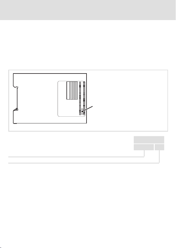
Identifikation
EMF2176IB
Type
Hans-Lenze-Straße 1
D31855 Aerzen
Made in Germany
Prod.-No.
Id.-No.
Ser.-No.
L
2176_005
c
33.2176IB. 1B
Gerätereihe
Hardwarestand
Einsetzbarkeit
Der CAN-Repeater wird eingesetzt
ƒ zur galvanischen Trennung von zwei Segmenten eines CAN-Netzwerks,
ƒ alsService-Schnittstelle (Zugriff mit Diagnose-Programmwährend des Betriebs).
EDKMF2176X DE/EN/FR 4.2
5
Page 6

Sicherheitshinweise
Verwendete Hinweise
1 Sicherheitshinweise
Verwendete Hinweise
Um auf Gefahren und wichtigeInformationen hinzuweisen, werden in dieser Dokumentation folgende Piktogramme und Signalwörter verwendet:
Sicherheitshinweise
Aufbau der Sicherheitshinweise:
Gefahr!
(kennzeichnet die Art und die Schwere der Gefahr)
Hinweistext
(beschreibt die Gefahr und gibt Hinweise, wie sie vermieden werden kann)
Piktogramm und Signalwort Bedeutung
Gefahr von Personenschäden durch gefährliche elektrische
Spannung
Gefahr!
Gefahr!
Stop!
Anwendungshinweise
Piktogramm und Signalwort Bedeutung
Hinweis auf eine unmittelbar drohende Gefahr, die den Tod
oder schwere Verletzungen zur Folge haben kann, wenn
nicht die entsprechenden Maßnahmen getroffen werden.
Gefahr von Personenschäden durch eine allgemeine Gefahrenquelle
Hinweis auf eine unmittelbar drohende Gefahr, die den Tod
oder schwere Verletzungen zur Folge haben kann, wenn
nicht die entsprechenden Maßnahmen getroffen werden.
Gefahr von Sachschäden
Hinweis auf eine mögliche Gefahr, die Sachschäden zur
Folge haben kann, wenn nicht die entsprechenden Maßnahmengetroffenwerden.
Hinweis!
Tipp!
EDKMF2176X DE/EN/FR 4.2
Wichtiger Hinweis für die störungsfreie Funktion
Nützlicher Tipp für die einfache Handhabung
Verweis auf andere Dokumentation
6
Page 7

Elektrische Installation
Wichtige Hinweise
2 ElektrischeInstallation
Wichtige Hinweise
Gefahr!
Unsachgemäßer Umgang mit dem CAN-Repeater und dem Grundgerät kann
schwere Personenschäden und Sachschäden verursachen.
Beachten Sie die in den Anleitungen zum Grundgerät enthaltenen
Sicherheitshinweise und Restgefahren.
Stop!
Beachten Sie für den störungsfreien Betrieb des CAN-Repeaters unbedingt die
folgenden Punkte:
ƒ Die Übertragungsrate muss in beiden CAN-Segementen gleich sein!
Bei unterschiedlichen Übertragungsraten fällt das gesamte Bus-System
aus (Zustand ”BUS-OFF”).
ƒ Verdrahten Sie sorgfältig!
Sind in einem Segment die CAN-Leitungen vertauscht, fällt das gesamte
Bus-System aus (Zustand ”BUS-OFF”).
ƒ 80 % Buslast nicht überschreiten!
Daten der Anschlussklemmen
Elektrischer Anschluss Steckerleiste mit Schraubanschluss
Anschlussmöglichkeiten
Abisolierlänge 6,5 mm
starr: 1.5 mm2(AWG 16)
flexibel:
ohne Aderendhülse
2
1,5 mm
(AWG 16)
mit Aderendhülse, ohne Kunststoffhülse
1,5 mm2(AWG 16)
mit Aderendhülse, mit Kunststoffhülse
0,5 mm2(AWG 20)
EDKMF2176X DE/EN/FR 4.2
7
Page 8

Elektrische Installation
Aufbau als galvanische Trennung
Aufbau als galvanische Trennung
Funktion
Der CAN-Repeater trennt einSegment automatisch ab, wenn im Segment eine permanenter Störpegel von +1 V ... +5 V zwischen CAN-HI und CAN-LO erkannt wird. Die entsprechende rote LED leuchtet. Das andere Segment arbeitet weiter.
Ist der permanente Störpegel nicht mehr vorhanden, schaltet der CAN-Repeater das Segment wieder automatisch zu.
Prinzipschaltbild
CAN 2.1
HI
CAN 1.1 … CAN 1.n Knoten im Segment CAN1
CAN 2.1 … CAN 2.n Knoten im Segment CAN2
Insgesamt sind maximal 63 Knoten möglich
EDKMF2176X DE/EN/FR 4.2
LO
GND
HI
GND
LO
120
CAN 2.n
HI
GND
LO
HI
GND
LO
HILOGND
120
120
HI
GND
LO
HI
GND
LO
CAN 1.1
8
CAN2
CAN1
HI
LO
GND
+24
=
GND
2176
+24VDC
(+9 ... +35 V DC)
120
HI
GND
LO
CAN 1.n
HI
GND
LO
2176_002
Page 9

Elektrische Installation
Aufbau als Service-Schnittstelle
Aufbau als Service-Schnittstelle
Funktion
ÜberdenPC können Sie z. B. mitdem Programm GlobalDrive Control (GDC) die Anlage während des Betriebs überwachen.
Hinweis!
ƒ Der Anschluss des PC-Systembusmoduls ist in der Montageanleitung
beschrieben, die mit dem Modul geliefert wird.
ƒ Vermerken Sie am CAN-Repeater die in der Anlage eingestellte
Übertragungsrate. Sie vermeiden dadurch Busausfälle und erleichtern dem
Service-Personal die Arbeit.
Prinzipschaltbild
CAN 2.1
HILOGND HILOGND
120
2173-V003 PC-Systembusmodul 2173, Variante V003 (mit galvanischer Trennung)
PC PC mit PS/2-Anschluss
CAN 2.1 … CAN 2.n Knoten im Segment CAN2, maximal 63 Knoten möglich
EDKMF2176X DE/EN/FR 4.2
CAN 2.n
HILOGND HILOGND
HILOGND
120
120
HI
GND
LO
2173-V003
9
CAN2
CAN1
+24
PC
+24VDC
=
(+9 ... +35 V DC)
GND
2176
2176_003
Page 10
Allgemeine Daten und Einsatzbedingungen
Technische Daten
3 TechnischeDaten
Allgemeine Daten und Einsatzbedingungen
Allgemeine Daten
Eigenschaften
Schnittstelle CAN Bus Interface
Baudrate bis zu 500 kBit/s
Signal-Laufzeit im Repeater ca. 150 ns von CAN1 zu CAN2,
Gehäuse Kunststoff-Hutschienengehäuse
Umgebungsbedingungen
Klimatische Bedingungen
Lagerung -25 °C … +60 °C
Transport -25 °C … +70 °C
Betrieb -20 °C … +60 °C
Verschmutzungsgrad 2 nach EN 50178
Schutzart IP20
Montagebedingungen
Einbauart Montage auf Hutschiene 35 × 7,5 mm
Anschlussdaten
Anschlussdaten
Anschlüsse Schraubklemmen
Spannungsversorgung DC 24 V (+9 … +35 V)
Leistungsaufnahme DC 24 V, 1,5 W typ.
z CAN1 und CAN2 über DC/DC-Wandler von der Stromversorgung
getrennt
z CAN1 von CAN2 über Optokoppler galvanisch getrennt
z CAN-Abschlusswiderstände in CAN1 und CAN2 integriert
ISO/IS 11898-2 (Philips 82C251 Transceiver)
d. h. die max. Buslänge verringert sich um ca. 30 m
EDKMF2176X DE/EN/FR 4.2
10
Page 11

Preface and general information
4 Prefaceand generalinformation
Please read these instructions and the documentation of the standard device
before you start working!
Observe the safety instructions given therein!
0
2
Connections
Pos. Description
DC-24-V supply voltage
Segment CAN2
Segment CAN1
L
Hans-Lenze-Straße 1
D31855 Aerzen
Made in Germany
1
24V
EMF2176IB
Type
Id.-No.
Prod.-No.
GND
4
3
HI
Ser.-No.
LO
CAN2
CAN1
1
5
GND
2
3
4
5
2176
6
2176_001
Displays
Pos. Colour Status Description
Red On Fault in segment CAN 2
Green On Transmission of segment CAN 2
Red On Fault in segment CAN 1
Green On Transmission of segment CAN 1
EDKMF2176X DE/EN/FR 4.2
11
Page 12

Mounting
Preface and general information
2176_008a
EDKMF2176X DE/EN/FR 4.2
12
Page 13

Dismounting
Preface and general information
2176_008b
EDKMF2176X DE/EN/FR 4.2
13
Page 14
Preface and general information
Validity information
These instructions are valid for
ƒ 2176 CAN repeaters with device status 33.2176IB as of version 1B
These instructions areonly valid togetherwith the documentation for the standarddevices
permitted for the application.
Identification
EMF2176IB
Typ e
Hans-Lenze-Straße 1
D31855 Aerzen
Made in Germany
Prod.-No.
Id.-No.
Ser.-No.
L
2176_005
c
33.2176IB. 1B
Series
Hardware version
Application range
The CAN repeater is used
ƒ for isolating two segments of a CAN network,
ƒ as a service interface (access via diagnostics program during operation).
EDKMF2176X DE/EN/FR 4.2
14
Page 15

Safety instructions
Notes used
5 Safetyinstru ctions
Notes used
The following pictographs and signal words are used in this documentation to indicate
dangers and important information:
Safety instructions
Structure of safety instructions:
Danger!
(characterises the type and severity of danger)
Note
(describes the danger and gives information about how to prevent dangerous
situations)
Pictograph and signal word Meaning
Danger of personal injury through dangerous electrical
voltage.
Danger!
Danger!
Stop!
Application notes
Pictograph and signal word Meaning
Reference to an imminent danger that may result in death
or serious personal injury if the corresponding measures are
not taken.
Danger of personal injury through a general source of
danger.
Reference to an imminent danger that may result in death
or serious personal injury if the corresponding measures are
not taken.
Danger of property damage.
Reference to a possible danger that may result in property
damage if the corresponding measures are not taken.
Note!
Tip!
EDKMF2176X DE/EN/FR 4.2
Important note to ensure troublefree operation
Useful tip for simple handling
Reference to another documentation
15
Page 16

Electrical installation
Important notes
6 Electricalinstallation
Important notes
Danger!
Improper handling of the CAN repeater and the basic device can cause severe
injuries to persons and damage to material assets.
Observe the safety instructions and residual hazards mentioned in the
instructions for the basic device.
Stop!
The following items must be observed for trouble-free operation of the CAN
repeater:
ƒ ThebaudratemustbeidenticalinbothCANsegments!
In case of different baud rates, the entire bus system fails (”BUS-OFF”
state).
ƒ Wire the system carefully!
IftheCANcablesarecrossedinasegment,theentirebussystemfails
(”BUS-OFF” state).
ƒ Do not exceed a bus load of 80 %!
Terminal data
Electrical connection Plug connector with screw connection
Possible connect ions
Stripping length 6.5 mm
rigid: 1.5 mm2(AWG 16)
flexible:
without wire end ferrule
2
1.5 mm
(AWG 16)
with wire end ferrule, without plastic sleeve
1.5 mm2(AWG 16)
with wire end ferrule, with plastic sleeve
0.5 mm2(AWG 20)
EDKMF2176X DE/EN/FR 4.2
16
Page 17

Electrical installation
Design as isolation
Design as isolation
Function
The CAN repeater automatically separates from a segment if the segment shows a
permanent disturbance level of +1 V ... +5 V between CAN-HI and CAN-LO. The
corresponding red LED is on. The other segment goes on working.
If the permanent disturbance level has disappeared, the segment is connected to the
system again through the CAN repeater.
Basic circuit diagram
CAN 2.1
HI
CAN 1.1 … CAN 1.n Nodes in segment CAN1
CAN 2.1 … CAN 2.n Nodes in segment CAN2
A total of max. 63 nodes possible
EDKMF2176X DE/EN/FR 4.2
LO
GND
HI
GND
LO
120
CAN 2.n
HI
GND
LO
HI
GND
LO
HILOGND
120
120
HI
GND
LO
HI
GND
LO
CAN 1.1
17
CAN2
CAN1
HI
LO
GND
+24
=
GND
2176
+24VDC
(+9 ... +35 V DC)
120
HI
GND
LO
CAN 1.n
HI
GND
LO
2176_002
Page 18

Electrical installation
Design as service interface
Design as service interface
Function
Via the PC you are able to monitor the system during operation, e.g. with the Global Drive
Control program (GDC).
Note!
ƒ The connection of the PC system bus module is described in the Mounting
Instructions supplied with the module.
ƒ Note the baud rate set in the system on the CAN repeater. This helps to
avoid bus failures and facilitates the work of the service personnel.
Basic circuit diagram
CAN 2.1
HILOGND HILOGND
120
2173-V003 PC system bus module 2173, version V003 (with electrical isolation)
PC PC with PS/2 connection
CAN 2.1 … CAN 2.n Nodes in the segment CAN2, max. 63 nodes possible
EDKMF2176X DE/EN/FR 4.2
CAN 2.n
HILOGND
HILOGND
HILOGND
120
120
HI
GND
LO
2173-V003
18
CAN2
CAN1
+24
PC
+24VDC
=
(+9 ... +35 V DC)
GND
2176
2176_003
Page 19

General data and operating conditions
Technical data
7 Technicaldata
General data and operating conditions
General data
Characteristics
Interface CAN bus interface
Baud rate Up to 500 kBit/s
Signal propagation delay
within the repeater
Housing Plastics DIN rail housing
Ambient conditions
Climatic conditions
Storage -25 °C … +60 °C
Transport -25 °C … +70 °C
Operation -20 °C … +60 °C
Degree of pollution 2 according to EN 50178
Enclosure IP20
Mounting conditions
Mounting type Mounting on 35 × 7.5 mm DIN rail
Connection data
Connection data
Connections Screw terminals
Voltage supply DC 24 V (+9 … +35 V)
Power input DC 24 V, 1.5 W typ.
z CAN1 and CAN2 disconnected from the current supply via
DC/DC converter
z CAN1 isolated from CAN2 via optocoupler
z CAN terminating resistors integrated in CAN1 and CAN2
ISO/IS 11898-2 (Philips 82C251 transceiver)
Approx. 150 ns from CAN1 to CAN2,
i. e. the max. bus length decreases by approx. 30 m
EDKMF2176X DE/EN/FR 4.2
19
Page 20

Avant-propos et généralités
8 Avant-proposet généralités
Lire le présentfascicule et la documentation relative à l’appareilde base avant
toute manipulation de l’équipement !
Respecter les consignes de sécurité fournies.
0
2
Raccordements
Pos. Description
Tension d’alimentation24 V CC
SegmentCAN2
SegmentCAN1
L
Hans-Lenze-Straße 1
D31855 Aerzen
Made in Germany
1
24V
EMF2176IB
Typ e
Id.-No.
Prod.-No.
GND
4
3
HI
Ser.-No.
1
5
GND
LO
2
2
AN
C
3
4
5
2176
1
AN
C
6
2176_001
Affichages
Pos. Couleur Etat Description
rouge allumé Défaut dans le segment CAN 2
vert allumé Envoi segmentCAN 2
rouge allumé Défaut dans le segment CAN 1
vert allumé Envoi segmentCAN 1
EDKMF2176X DE/EN/FR 4.2
20
Page 21

Montage
Avant-propos et généralités
2176_008a
EDKMF2176X DE/EN/FR 4.2
21
Page 22

Démontage
Avant-propos et généralités
2176_008b
EDKMF2176X DE/EN/FR 4.2
22
Page 23

Avant-propos et généralités
Informationsrelatives à la validité
Le présent documents’appliqueau produitsuivant :
ƒ pour répétiteur CAN 2176 avec le modèle d’appareil 33. 2176IB à partir de la ve rsion
1B
Ce document est uniquement valable avec la documentation relative aux appareils de base
compatibles.
Identification
EMF2176IB
Typ e
Hans-Lenze-Straße 1
D31855 Aerzen
Made in Germany
Prod.-No.
Id.-No.
Ser.-No.
L
2176_005
c
33.2176IB. 1B
Série d’appareil
Versionmatérielle
Utilisation
Le répétiteur CAN est utilisé
ƒ comme interface de service pour assurerl’isolation galvanique de deux segments
d’un réseau CAN ,
ƒ (accès avec le programme de diagnostic pendantle fonctionnement).
EDKMF2176X DE/EN/FR 4.2
23
Page 24

Consignes de sécurité
Consignes utilisées
9 Consignesdesécurité
Consignes utilisées
Pour indiquer des risques et des informations importantes, la présente documentation
utilise les mots et symboles suivants :
Consignes de s écurité
Présentation des consignes de sécurité
Danger !
(Lepictogrammeindiqueletypederisque.)
Explication
(L’explication décrit le risque et les moyens de l’éviter.)
Pictogramme et mot associé Explication
Situation dangereuse pour les personnes en raison d’une
tension électrique élevée
Danger !
Danger !
Stop !
Indication d’un danger imminent qui peut avoir pour
conséquences des blessures mortelles ou très graves en
cas de non-respect des consignes de sécurité
correspondantes
Situation dangereuse pour les personnes en raison d’un
danger d’ordre général
Indication d’un danger imminent qui peut avoir pour
conséquences des blessures mortelles ou très graves en
cas de non-respect des consignes de sécurité
correspondantes
Risques de dégâts matériels
Indication d’un risque potentiel qui peut avoir pour
conséquences des dégâts matériels en cas de non-respect
des consignes de sécurité correspondantes
EDKMF2176X DE/EN/FR 4.2
24
Page 25

Consignes de sécurité
Consignes utilisées
Consignes d’utilisation
Pictogramme et mot associé Explication
Remarque
importante !
Conseil !
Remarque importante pour assurer un fonctionnement
correct
Conseil utile pour faciliter la mise en oeuvre
Référence à une autre documentation
EDKMF2176X DE/EN/FR 4.2
25
Page 26

Installation électrique
Remarques importantes
10 Installationélectrique
Remarques importantes
Danger !
L’utilisation inappropriée du répétiteur CAN et de l’appareil de base peut
entraîner de graves dommages corporels et matériels.
Tenir compte des consignes de sécurité et des dangers résiduels énoncés dans
les instructions d’utilisation de l’appareil de base.
Stop !
Respecter impérativement les points suivants afin d’assurer la fonctionnalité
sans problème du répétiteur CAN.
ƒ Lavitessedetransmissiondoitêtreidentique pour les deux segments CAN
!
Si les vitesses de transmission sont différentes, l’ensemble du bus est
inopérant (état : ”BUS-OFF”).
ƒ Lecâblagedoitêtreréaliséavecsoin!
Si les câbles CAN sont échangés dans un segment, l’ensemble du bus est
inopérant (état ”BUS-OFF”).
ƒ Ne pas dépasser une charge bus de 80 % !
Spécifications pour bornier de raccordement
Raccordement électrique Bornier à vis
Raccordements possibles
Fil dénudé 6,5 mm
Rigide : 1,5 mm2(AWG 16)
Flexible :
sans embout
1,5 mm2(AWG 16)
avec embout, sans gaine plastifiée
1,5 mm2(AWG 16)
avec embout et gaine plastifiée
0,5 mm2(AWG 20)
EDKMF2176X DE/EN/FR 4.2
26
Page 27

Installation électrique
Câblage avec isolation galvanique
Câblage avec isolation galvanique
Fonction
Le répétiteur CAN active la coupure automatique d’un segment dès qu’un niveau de
perturbations de +1 V ... +5 V entre CAN-HI et CAN-LO est détecté. La LED rouge
correspondante est alors allumée. L’autre segment continue à fonctionner.
La coupure est automatiquement désactivée par le répétiteur CAN dès que le niveau de
perturbations permanent est éliminé.
Schéma de principe
CAN 2.1
HI
CAN 1.1 … CAN 1.n Elément sur le segment CAN1
CAN 2.1 … CAN 2.n Elément sur le segment CAN2
63 éléments possibles au maximum
EDKMF2176X DE/EN/FR 4.2
LO
GND
HI
GND
LO
120
CAN 2.n
HI
LO
GND
HI
LO
HILOGND
HI
LO
HI
LO
120
120
27
GND
GND
GND
CAN 1.1
CAN2
CAN1
HI
LO
GND
+24
=
GND
2176
+24VDC
(+9 ... +35 V DC)
120
HI
GND
LO
CAN 1.n
HI
GND
LO
2176_002
Page 28

Installation électrique
Câblage avec interface de service
Câblage avec interface de service
Fonction
L’installation peut être surveillée pendant le fonctionnement via PC à l’aidedu programme
Global Drive Control (GDC) par exemple.
Remarque importante !
ƒ Pour le raccordement du module Bus Système PC, se reporter aux
instructions de montage comprises dans l’emballage du module.
ƒ Marquer sur le répétitieur CAN la vitesse de transmission réglée pour
l’installation afin d’éviter des pannes de bus et de faciliter les travaux pour
le personnel de service.
Schéma de principe
CAN 2.1
HILOGND HILOGND
120
2173-V003 Module bus système PC 2173, variante V003 (avec isolation galvanique)
PC PC avec raccordement PS/2
CAN 2.1 … CAN 2.n Elément sur le segment CAN2, 63 éléments possibles au maximum
EDKMF2176X DE/EN/FR 4.2
CAN 2.n
HILOGND HILOGND
HILOGND
120
120
HI
GND
LO
2173-V003
28
CAN2
CAN1
+24
PC
+24VDC
=
(+9 ... +35 V DC)
GND
2176
2176_003
Page 29
Caractéristiques générales et conditions d’utilisation
Spécifications techniques
11 Spécificationstechniques
Caractéristiques générales et conditions d’utilisation
Caractéristiques générales
Caractéristiques
Interface Interface du bus CAN
Vitesse de transmission Jusqu’à 500 kbits/s
Temps de parcours du signal
dans le répétiteur
Boîtier Boîtier en plastique pour profilé chapeau
Conditions ambiantes
Conditions climatiques
Stockage -25 °C … +60 °C
Transport -25 °C … +70 °C
Fonctionnement -20 °C … +60 °C
Degré de pollution 2 selon EN 50178
Indice de protection IP20
Conditions de montage
Type de montage Montage sur profilé chapeau 35 × 7,5 mm
Données de raccordement
Données de raccordement
Raccordements Bornier à vis
Tension d’alimentation 24 V CC (+9 … +35 V)
Puissance absorbée 24 V CC, 1,5 W typ.
z CAN1 et CAN2 isolés de l’alimentation électrique par un
convertisseur continu-continu
z CAN1 isolé galvaniquement de CAN2 par optocoupleur
z Résistances d’extrémité du bus CAN intégrées dans CAN1 et
CAN2
ISO/IS 11898-2 (émetteur-récepteur Philips 82C251)
Env. 150 ns entre CAN1 et CAN2,
c’est-à-dire que la longueur de bus max. se réduit d’env. 30 m
EDKMF2176X DE/EN/FR 4.2
29
Page 30

© 06/2010
Lenze Automation GmbH
)
Hans-Lenze-Str. 1
D-31855 Aerzen
Germany
+49 (0)51 54 / 82-0
¬
+49(0)5154/82-2800
|
Lenze@Lenze.de
Þ
www.Lenze.com
Service Lenze Service GmbH
Breslauer Straße 3
D-32699 Extertal
Germany
00 80 00 / 24 4 68 77 (24 h helpline)
¬
+49 (0)51 54 / 82-11 12
|
Service@Lenze.de
EDKMF2176X.6ShDE/EN/FR4.2TD00
10987654321
 Loading...