

Page 1
EDSMF2133IB
.G÷h
Ä.G÷hä
L−force Communication
Communication Manual
PROFIBUS−DP
EMF2133IB
Communication module
l
Page 2

Contentsi
1 About this documentation 5 . . . . . . . . . . . . . . . . . . . . . . . . . . . . . . . . . . . . . . . . . . . . . . . . . .
1.1 Document history 6 . . . . . . . . . . . . . . . . . . . . . . . . . . . . . . . . . . . . . . . . . . . . . . . . . . . .
1.2 Conventions used 7 . . . . . . . . . . . . . . . . . . . . . . . . . . . . . . . . . . . . . . . . . . . . . . . . . . . .
1.3 Terminology used 8 . . . . . . . . . . . . . . . . . . . . . . . . . . . . . . . . . . . . . . . . . . . . . . . . . . . .
1.4 Notes used 9 . . . . . . . . . . . . . . . . . . . . . . . . . . . . . . . . . . . . . . . . . . . . . . . . . . . . . . . . . .
2 Safety instructions 10 . . . . . . . . . . . . . . . . . . . . . . . . . . . . . . . . . . . . . . . . . . . . . . . . . . . . . . . . .
2.1 General safety information 10 . . . . . . . . . . . . . . . . . . . . . . . . . . . . . . . . . . . . . . . . . . . .
2.2 Device− and application−specific safety instructions 11 . . . . . . . . . . . . . . . . . . . . . . . .
2.3 Residual hazards 11 . . . . . . . . . . . . . . . . . . . . . . . . . . . . . . . . . . . . . . . . . . . . . . . . . . . . .
3 Product description 12 . . . . . . . . . . . . . . . . . . . . . . . . . . . . . . . . . . . . . . . . . . . . . . . . . . . . . . . .
3.1 Application as directed 12 . . . . . . . . . . . . . . . . . . . . . . . . . . . . . . . . . . . . . . . . . . . . . . .
3.2 Identification 13 . . . . . . . . . . . . . . . . . . . . . . . . . . . . . . . . . . . . . . . . . . . . . . . . . . . . . . . .
3.3 Product features 14 . . . . . . . . . . . . . . . . . . . . . . . . . . . . . . . . . . . . . . . . . . . . . . . . . . . . .
3.4 Connections and interfaces 15 . . . . . . . . . . . . . . . . . . . . . . . . . . . . . . . . . . . . . . . . . . . .
4 Technical data 16 . . . . . . . . . . . . . . . . . . . . . . . . . . . . . . . . . . . . . . . . . . . . . . . . . . . . . . . . . . . .
4.1 General data 16 . . . . . . . . . . . . . . . . . . . . . . . . . . . . . . . . . . . . . . . . . . . . . . . . . . . . . . . .
4.2 Protective insulation 17 . . . . . . . . . . . . . . . . . . . . . . . . . . . . . . . . . . . . . . . . . . . . . . . . . .
4.3 Communication time 18 . . . . . . . . . . . . . . . . . . . . . . . . . . . . . . . . . . . . . . . . . . . . . . . . .
4.3.1 Processing time 820X 18 . . . . . . . . . . . . . . . . . . . . . . . . . . . . . . . . . . . . . . . . . .
4.3.2 Processing time 821X / 822X / 824X / 8200 vector 19 . . . . . . . . . . . . . . . . .
4.3.3 Processing time 93XX / ECSxS 19 . . . . . . . . . . . . . . . . . . . . . . . . . . . . . . . . . .
4.3.4 Processing time DrivePLC/ 9300ServoPLC/ ECSxA 19 . . . . . . . . . . . . . . . .
4.4 Dimensions 20 . . . . . . . . . . . . . . . . . . . . . . . . . . . . . . . . . . . . . . . . . . . . . . . . . . . . . . . . . .
5 Installation 21 . . . . . . . . . . . . . . . . . . . . . . . . . . . . . . . . . . . . . . . . . . . . . . . . . . . . . . . . . . . . . . .
5.1 Mechanical installation 22 . . . . . . . . . . . . . . . . . . . . . . . . . . . . . . . . . . . . . . . . . . . . . . . .
5.2 Electrical installation 23 . . . . . . . . . . . . . . . . . . . . . . . . . . . . . . . . . . . . . . . . . . . . . . . . . .
5.2.1 Wiring according to EMC (CE−typical drive system) 23 . . . . . . . . . . . . . . . . .
5.2.2 Wiring with a host (master) 24 . . . . . . . . . . . . . . . . . . . . . . . . . . . . . . . . . . . .
5.2.3 Connection of the PROFIBUS 27 . . . . . . . . . . . . . . . . . . . . . . . . . . . . . . . . . . .
5.2.4 Voltage supply 28 . . . . . . . . . . . . . . . . . . . . . . . . . . . . . . . . . . . . . . . . . . . . . .
5.2.5 Cable cross−sections and screw−tightening torques 30 . . . . . . . . . . . . . . . . .
6 Commissioning 31 . . . . . . . . . . . . . . . . . . . . . . . . . . . . . . . . . . . . . . . . . . . . . . . . . . . . . . . . . . .
6.1 Before switching on 31 . . . . . . . . . . . . . . . . . . . . . . . . . . . . . . . . . . . . . . . . . . . . . . . . . .
6.2 Initial switch−on 32 . . . . . . . . . . . . . . . . . . . . . . . . . . . . . . . . . . . . . . . . . . . . . . . . . . . . . .
6.3 Configuring the host system (master) 34 . . . . . . . . . . . . . . . . . . . . . . . . . . . . . . . . . . .
6.4 Activating the bus terminating resistor 37 . . . . . . . . . . . . . . . . . . . . . . . . . . . . . . . . . .
l 2
EDSMF2133IB EN 5.0
Page 3

Contents i
6.5 Setting the software compatibility 37 . . . . . . . . . . . . . . . . . . . . . . . . . . . . . . . . . . . . . .
6.6 Preparing the standard device for communication 38 . . . . . . . . . . . . . . . . . . . . . . . .
6.6.1 Frequency inverter 82XX / 8200 vector 38 . . . . . . . . . . . . . . . . . . . . . . . . . . .
6.6.2 93XX servo inverter / 9300 Servo PLC 39 . . . . . . . . . . . . . . . . . . . . . . . . . . . .
6.6.3 Drive PLC 40 . . . . . . . . . . . . . . . . . . . . . . . . . . . . . . . . . . . . . . . . . . . . . . . . . . . .
6.6.4 Axis modules ECSxS / ECSxA 41 . . . . . . . . . . . . . . . . . . . . . . . . . . . . . . . . . . . .
6.7 Setting the node address 42 . . . . . . . . . . . . . . . . . . . . . . . . . . . . . . . . . . . . . . . . . . . . .
6.7.1 Setting via code 42 . . . . . . . . . . . . . . . . . . . . . . . . . . . . . . . . . . . . . . . . . . . . . .
6.7.2 Settings via DIP switch 42 . . . . . . . . . . . . . . . . . . . . . . . . . . . . . . . . . . . . . . . .
6.7.3 Settings by a master (class 2) 43 . . . . . . . . . . . . . . . . . . . . . . . . . . . . . . . . . . .
6.8 Connecting the mains voltage 44 . . . . . . . . . . . . . . . . . . . . . . . . . . . . . . . . . . . . . . . . . .
7 Process data transfer 45 . . . . . . . . . . . . . . . . . . . . . . . . . . . . . . . . . . . . . . . . . . . . . . . . . . . . . . .
7.1 Lenze device control 46 . . . . . . . . . . . . . . . . . . . . . . . . . . . . . . . . . . . . . . . . . . . . . . . . .
7.1.1 Setpoint source selection 46 . . . . . . . . . . . . . . . . . . . . . . . . . . . . . . . . . . . . . .
7.1.2 Process data signals for 82XX frequency inverters 47 . . . . . . . . . . . . . . . . . .
7.1.3 Process data signals for 8200 vector frequency inverters 52 . . . . . . . . . . . .
7.1.4 Process data signal for 9300 servo inverters 57 . . . . . . . . . . . . . . . . . . . . . . .
7.1.5 Process data signals for 9300 Servo PLC and Drive PLC 63 . . . . . . . . . . . . . .
7.1.6 Process data signals for axis modules ECSxS / ECSxA 67 . . . . . . . . . . . . . . .
7.2 DRIVECOM control 68 . . . . . . . . . . . . . . . . . . . . . . . . . . . . . . . . . . . . . . . . . . . . . . . . . . . .
7.2.1 Provide DRIVECOM compatibility 68 . . . . . . . . . . . . . . . . . . . . . . . . . . . . . . .
7.2.2 DRIVECOM state machine 69 . . . . . . . . . . . . . . . . . . . . . . . . . . . . . . . . . . . . . .
7.2.3 DRIVECOM control word 71 . . . . . . . . . . . . . . . . . . . . . . . . . . . . . . . . . . . . . . .
7.2.4 DRIVECOM status word 73 . . . . . . . . . . . . . . . . . . . . . . . . . . . . . . . . . . . . . . . .
7.2.5 Bit control commands 75 . . . . . . . . . . . . . . . . . . . . . . . . . . . . . . . . . . . . . . . . .
7.2.6 Status bits 76 . . . . . . . . . . . . . . . . . . . . . . . . . . . . . . . . . . . . . . . . . . . . . . . . . . .
7.3 PROFIdrive control 77 . . . . . . . . . . . . . . . . . . . . . . . . . . . . . . . . . . . . . . . . . . . . . . . . . . . .
7.3.1 Establishing PROFIdrive compatibility 77 . . . . . . . . . . . . . . . . . . . . . . . . . . .
7.3.2 PROFIdrive state machine 78 . . . . . . . . . . . . . . . . . . . . . . . . . . . . . . . . . . . . . .
7.3.3 PROFIdrive control word 79 . . . . . . . . . . . . . . . . . . . . . . . . . . . . . . . . . . . . . . .
7.3.4 PROFIdrive status word 81 . . . . . . . . . . . . . . . . . . . . . . . . . . . . . . . . . . . . . . . .
8 Parameter data transfer 82 . . . . . . . . . . . . . . . . . . . . . . . . . . . . . . . . . . . . . . . . . . . . . . . . . . . .
8.1 Lenze parameter sets 83 . . . . . . . . . . . . . . . . . . . . . . . . . . . . . . . . . . . . . . . . . . . . . . . . .
8.1.1 Parameter sets for 82XX controllers 83 . . . . . . . . . . . . . . . . . . . . . . . . . . . . . .
8.1.2 Parameter sets for 8200 vector controller 84 . . . . . . . . . . . . . . . . . . . . . . . . .
8.1.3 Parameter sets for controller 93XX 85 . . . . . . . . . . . . . . . . . . . . . . . . . . . . . .
8.1.4 Parameter sets for Drive PLC and ECSxS / ECSxA axis modules 86 . . . . . . .
EDSMF2133IB EN 5.0
l 3
Page 4

Contentsi
8.2 DRIVECOM parameter data channel 87 . . . . . . . . . . . . . . . . . . . . . . . . . . . . . . . . . . . . .
8.2.1 Addressing of the parameter data 87 . . . . . . . . . . . . . . . . . . . . . . . . . . . . . . .
8.2.2 Addressing of the Lenze parameters 87 . . . . . . . . . . . . . . . . . . . . . . . . . . . . .
8.2.3 Telegram structure 87 . . . . . . . . . . . . . . . . . . . . . . . . . . . . . . . . . . . . . . . . . . . .
8.2.4 Error codes (DRIVECOM) 91 . . . . . . . . . . . . . . . . . . . . . . . . . . . . . . . . . . . . . . .
8.2.5 Reading parameters 92 . . . . . . . . . . . . . . . . . . . . . . . . . . . . . . . . . . . . . . . . . . .
8.2.6 Writing parameters 94 . . . . . . . . . . . . . . . . . . . . . . . . . . . . . . . . . . . . . . . . . . .
8.3 PROFIdrive parameter data channel 96 . . . . . . . . . . . . . . . . . . . . . . . . . . . . . . . . . . . . .
8.3.1 PROFIdrive DP−V1 97 . . . . . . . . . . . . . . . . . . . . . . . . . . . . . . . . . . . . . . . . . . . . .
8.3.2 Error codes (PROFIdrive) 109 . . . . . . . . . . . . . . . . . . . . . . . . . . . . . . . . . . . . . . . .
8.4 Consistent parameter data 110 . . . . . . . . . . . . . . . . . . . . . . . . . . . . . . . . . . . . . . . . . . . . .
9 Diagnostics 112 . . . . . . . . . . . . . . . . . . . . . . . . . . . . . . . . . . . . . . . . . . . . . . . . . . . . . . . . . . . . . . .
9.1 LED status displays 112 . . . . . . . . . . . . . . . . . . . . . . . . . . . . . . . . . . . . . . . . . . . . . . . . . .
9.2 Troubleshooting and fault elimination 113 . . . . . . . . . . . . . . . . . . . . . . . . . . . . . . . . . . .
9.2.1 Controller is inhibited 113 . . . . . . . . . . . . . . . . . . . . . . . . . . . . . . . . . . . . . . . . .
9.2.2 Checking PROFIBUS 115 . . . . . . . . . . . . . . . . . . . . . . . . . . . . . . . . . . . . . . . . . . .
9.2.3 Activation of communication module 116 . . . . . . . . . . . . . . . . . . . . . . . . . . . .
9.2.4 Reset fault (TRIP) 117 . . . . . . . . . . . . . . . . . . . . . . . . . . . . . . . . . . . . . . . . . . . . .
9.3 Monitoring with interrupted PROFIBUS communication 118 . . . . . . . . . . . . . . . . . . . .
9.3.1 Permanent interruption of communication 118 . . . . . . . . . . . . . . . . . . . . . . .
10 Codes 120 . . . . . . . . . . . . . . . . . . . . . . . . . . . . . . . . . . . . . . . . . . . . . . . . . . . . . . . . . . . . . . . . . . . .
11 Index table 125 . . . . . . . . . . . . . . . . . . . . . . . . . . . . . . . . . . . . . . . . . . . . . . . . . . . . . . . . . . . . . . .
12 Appendix 126 . . . . . . . . . . . . . . . . . . . . . . . . . . . . . . . . . . . . . . . . . . . . . . . . . . . . . . . . . . . . . . . .
13 Index 129 . . . . . . . . . . . . . . . . . . . . . . . . . . . . . . . . . . . . . . . . . . . . . . . . . . . . . . . . . . . . . . . . . . . .
9.3.2 Short−time interruption of communication 119 . . . . . . . . . . . . . . . . . . . . . . . .
10.1 Overview 120 . . . . . . . . . . . . . . . . . . . . . . . . . . . . . . . . . . . . . . . . . . . . . . . . . . . . . . . . . . . .
10.2 Monitoring codes 122 . . . . . . . . . . . . . . . . . . . . . . . . . . . . . . . . . . . . . . . . . . . . . . . . . . . . .
10.3 Diagnostics codes 124 . . . . . . . . . . . . . . . . . . . . . . . . . . . . . . . . . . . . . . . . . . . . . . . . . . . .
11.1 DRIVECOM profile parameter 125 . . . . . . . . . . . . . . . . . . . . . . . . . . . . . . . . . . . . . . . . . . .
12.1 Parallel operation of AIF and FIF interfaces 126 . . . . . . . . . . . . . . . . . . . . . . . . . . . . . . . .
12.2 Accessories 128 . . . . . . . . . . . . . . . . . . . . . . . . . . . . . . . . . . . . . . . . . . . . . . . . . . . . . . . . . .
l 4
EDSMF2133IB EN 5.0
Page 5

0Fig. 0Tab. 0
1 About this documentation
Contents
This documentation only contains descriptions for the EMF2133IB communication
module (PROFIBUS−DP).
) Note!
This documentation supplements the mounting instructions supplied with the
communication module and the documentations for the standard devices
used.
The mounting instructions contain safety instructions which must be
observed!
ƒ The features and functions of the communication module are described in detail.
About this documentation 1
ƒ Examples illustrate typical applications.
ƒ Furthermore this documentation contains the following:
– Safety instructions that must be observed.
– Key technical data relating to the communication module
– Information on versions of Lenze standard devices to be used.
– Notes on troubleshooting and fault elimination
The theoretical correlations are only explained in so far as they are necessary for
comprehending the function of the function module.
This documentation does not describe the software of an original equipment
manufacturer. No responsibility is taken for corresponding information given in this
manual. Information on how to use the software can be obtained from the documents of
the host system (master).
All brand names mentioned in this manual are trademarks of their respective companies.
Validity information
The information given in this documentation is valid for the following devices:
Communication module Type designation From hardware version From software version
PROFIBUS−DP EMF2133IB V2 0x
EDSMF2133IB EN 5.0
Target group
This documentation is intended for all persons who plan, install, commission and maintain
the networking and remote service of a machine.
I Tip!
Information and auxiliary devices around the Lenze products can be found in
the download area at
http://www.Lenze.com
l
5
Page 6

1
About this documentation
Document history
1.1 Document history
Material no. Version Description
− 1.0 11/2001 TD06 First edition
− 2.0 06/2004 TD06 l As of software version 1.2: Code C1882 added
− 4.0 12/2006 TD17 l As of software version 1.3: code C1883 added
.G÷h 5.0 09/2011 TD14 l Extended information on PROFIBUS DP−V1.
Your opinion is important to us!
These instructions were created to the best of our knowledge and belief to give you the
best possible support for handling our product.
If you have suggestions for improvement, please e−mail us to:
l Complete revision:
– Layout change
– New German orthography
l Structural and editorial adjustments
Extended descriptions for the use on the ECS servo system.
l Structural and editorial adjustments
feedback−docu@Lenze.de
Thank you for your support.
Your Lenze documentation team
6
l
EDSMF2133IB EN 5.0
Page 7

1.2 Conventions used
This documentation uses the following conventions to distinguish between different
types of information:
Type of information Identification Examples/notes
Spelling of numbers
Decimal separator
Decimal Standard notation For example: 1234
Hexadecimal 0x[0 ... 9, A ... F] For example: 0x60F4
Binary
l Nibble
Text
Program name » « PC software
Icons
Page reference ^ Reference to another page with additional
About this documentation
Conventions used
Point In general, the decimal point is used.
For instance: 1234.56
In quotation marks
Point
For example: ´100´
For example: ´0110.0100´
For example: »Engineer«, »Global Drive
Control« (GDC)
information
For instance: ^ 16 = see page 16
1
EDSMF2133IB EN 5.0
l
7
Page 8

1
About this documentation
Terminology used
1.3 Terminology used
Term Meaning
PROFIBUS The term stands for the PROFIBUS−DP variant according to IEC 61158 / IEC 61784. A
Standard device Lenze controllers/frequency inverters with which the communication module can be
Controller
Frequency inverter
Master PROFIBUS station which takes over the master function in the fieldbus system.
Slave PROFIBUS station representing a slave in the fieldbus system.
Code "Container" for one or several parameters used for parameter setting or monitoring of
Subcode If a code contains several parameters, they are stored under "subcodes".
POW Process output data word
PIW Process input data word
different PROFIBUS variant is not described in these Instructions.
used.
^ 12
the controller.
The documentation uses a slash "/" as a separator between code and subcode
(e.g. "C00118/3").
l 8
EDSMF2133IB EN 5.0
Page 9

1.4 Notes used
The following pictographs and signal words are used in this documentation to indicate
dangers and important information:
Safety instructions
Structure of safety instructions:
} Danger!
(characterises the type and severity of danger)
Note
(describes the danger and gives information about how to prevent dangerous
situations)
Pictograph and signal word Meaning
{ Danger!
} Danger!
( Stop!
About this documentation
Notes used
Danger of personal injury through dangerous electrical voltage.
Reference to an imminent danger that may result in death or
serious personal injury if the corresponding measures are not
taken.
Danger of personal injury through a general source of danger.
Reference to an imminent danger that may result in death or
serious personal injury if the corresponding measures are not
taken.
Danger of property damage.
Reference to a possible danger that may result in property
damage if the corresponding measures are not taken.
1
Application notes
Pictograph and signal word Meaning
) Note!
I Tip!
,
Important note to ensure troublefree operation
Useful tip for simple handling
Reference to another documentation
EDSMF2133IB EN 5.0
l
9
Page 10

2
Safety instructions
General safety information
2 Safety instructions
) Note!
It is absolutely vital that the stated safety measures are implemented in order
to prevent serious injury to persons and damage to material assets.
Always keep this documentation to hand in the vicinity of the product during
operation.
2.1 General safety information
} Danger!
Disregarding the following basic safety measures may lead to severe personal
injury and damage to material assets!
ƒ Lenze drive and automation components ...
... must only be used for the intended purpose.
... must never be operated if damaged.
... must never be subjected to technical modifications.
... must never be operated unless completely assembled.
... must never be operated without the covers/guards.
... can − depending on their degree of protection − have live, movable or rotating parts
during or after operation. Surfaces can be hot.
ƒ All specifications of the corresponding enclosed documentation must be observed.
This is vital for a safe and trouble−free operation and for achieving the specified product
features.
The procedural notes and circuit details provided in this document are proposals which
the user must check for suitability for his application. The manufacturer does not
accept any liability for the suitability of the specified procedures and circuit proposals.
ƒ Only qualified skilled personnel are permitted to work with or on Lenze drive and
automation components.
According to IEC 60364 or CENELEC HD 384, these are persons ...
... who are familiar with the installation, assembly, commissioning and operation of
the product,
... possess the appropriate qualifications for their work,
... and are acquainted with and can apply all the accident prevent regulations, directives
and laws applicable at the place of use.
10
l
EDSMF2133IB EN 5.0
Page 11

Device− and application−specific safety instructions
2.2 Device− and application−specific safety instructions
ƒ During operation, the communication module must be securely connected to the
standard device.
ƒ With external voltage supply, always use a separate power supply unit, safely
separated in accordance with EN 61800−5−1 in every control cabinet ("SELV" /
"PELV").
ƒ Only use cables that comply with the given specifications (¶ 25).
, Documentation for the standard device, control system, system/machine
All the other measures prescribed in this documentation must also be
implemented. Observe the safety instructions and application notes stated in
this manual.
2.3 Residual hazards
Safety instructions
2
Protection of persons
ƒ If the controllers are used on a phase earthed mains with a rated mains voltage
400 V, protection against accidental contact is not ensured without implementing
external measures. (See chapter "4.2", ^ 17)
Device protection
ƒ The module contains electronic components that can be damaged or destroyed by
electrostatic discharge.
EDSMF2133IB EN 5.0
l
11
Page 12

3
Product description
Application as directed
3 Product description
3.1 Application as directed
The communication module ...
ƒ is an accessory module which can be used in conjunction with the following Lenze
standard devices:
Device type Design
82EVxxxxxBxxxXX Vx 1x 8200 vector
82CVxxxxxBxxxXX Vx 1x 8200 vector, cold plate
82DVxxxKxBxxxXX Vx 1x 8200 vector, thermally
EPL 10200 E 1x 8x Drive PLC
33.93XX xE. 2x 1x Vxxx 9321 − 9332
33.938X xE. 1x 0x 9381 − 9383
33.93XX xC. 2x 1x Vxxx 9321 − 9332, cold plate
33.93XX EI / ET 2x 8x Vxxx 9300 Servo PLC
33.93XX CI / CT 2x 8x Vxxx 9300 Servo PLC, Cold plate
ECSxSxxxx4xxxxXX
ECSxPxxxx4xxxxXX
ECSxMxxxx4xxxxXX
ECSxAxxxx4xxxxXX
1) The standard device cannot be used with the DRIVECOM or PROFIdrive control.
ƒ is a device intended for use in industrial power systems.
1)
1)
1)
1)
Version
HW SW
1A 6.0 ECSxS (Speed and Torque)
1A 6.0 ECSxP (Posi and Shaft)
1A 6.0 ECSxM (Motion)
1A 2.3 ECSxA (Application)
Variant Explanation
separated
Any other use shall be deemed inappropriate!
12
l
EDSMF2133IB EN 5.0
Page 13
Product description
Identification
3
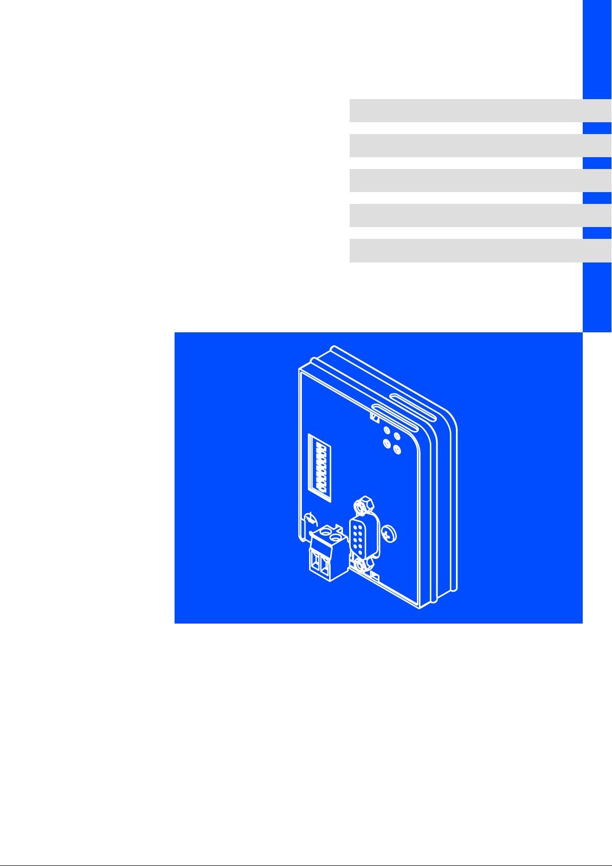
3.2 Identification
L
1D74
K
Type
Id.-No.
Prod.-No.
Ser.-No.
Input
E82AF000P0B201XX
Series
Hardware version
Software version
9371BC019
W 33.2133IB Vx 0X
EDSMF2133IB EN 5.0
l
13
Page 14

3
3.3 Product features
Product description
Product features
ƒ Interface module for the PROFIBUS communication system with the
PROFIBUS−DP−V0 (DRIVECOM profile) and PROFIBUS−DP−V1 (PROFIdrive)
communication profiles
ƒ Drive profiles:
– DRIVECOM profile "drive technology 20" (can be switched off)
– PROFIdrive (can be switched off, state machine and PROFIdrive parameter data
channel)
ƒ Support of the I&M0 functionality for identifying the standard device
ƒ Automatic detection of the baud rate (9.6 kbps ... 12 Mbps)
ƒ Optionally up to 12 process data words (depending on the basic device)
ƒ Acyclic parameter access via DP−V1
ƒ Access to all Lenze parameters
ƒ External 24V supply for maintaining the PROFIBUS network if the standard device
fails
ƒ DIP switches for ...
– Setting of the node address
– Setting of the compatibility to the Lenze PROFIBUS communication module
EMF2131IB
ƒ LED status displays:
– Voltage supply of the communication module
– Connection from the communication module to the PROFIBUS network
– Connection from the communication module to the standard device
– Operating statuses of the standard device
14
l
EDSMF2133IB EN 5.0
Page 15
3.4 Connections and interfaces
Product description
Connections and interfaces
3
EMF2133IB
01
2
4
6
2133
2133PFB003 2102LEC007
information
^ 112
^ 37
^ 42
^ 27
^ 29
2131
8
7
64
32
16
123456
24V DC
+
L
PROFIBUS DP
8
4
Adresse
2
1
_
ONOFF
3
5
7
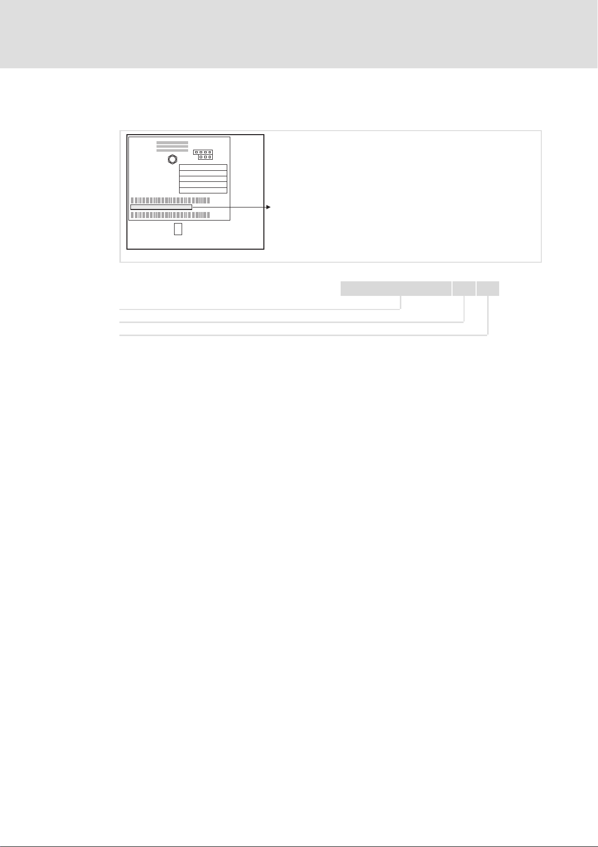
Fig. 3−1 EMF2133IB communication module (PROFIBUS−DP)
Pos. Description Detailed
0 Status of the voltage supply (green LED)
1 Status of the PROFIBUS communication (yellow LED)
2 Operating status of the standard device (red/green LED)
3 DIP switches for setting the ...
l Compatibility with the PROFIBUS communication module EMF2131IB
l Station address
4 PROFIBUS connection (Sub−D socket, 9−pole) ^ 24
5 Connection for external voltage supply
(Plug connector with screw connection, 2−pole)
7 PE connection (only with 82XX)
6 Fixing screw
8 Nameplate ^ 13
) Note!
Only for 820X and 821X:
If required, use an additional PE shield cable which avoids EMC−related
communication interference in surroundings with extreme disturbances.
EDSMF2133IB EN 5.0
l
15
Page 16

4
Technical data
General data
4 Technical data
4.1 General data
Area Values
Order designation EMF2133IB
PNO ID number 2133
Communication profile
(DIN 19245 Part 1 and Part3)
Communication medium RS485
Interface 9−pin Sub−D socket
Drive profile l DRIVECOM profile "drive technology 20" (can be switched off)
Network topology l without repeaters: Line
PROFIBUS nodes Slave
Baud rate [kbps] 9.6 ... 12000 (automatic detection)
Process data words 1 ... 12 words
DP user data length 1 ... 12 process data words +
Max. number of stations l Standard: 32 (= 1 bus segment)
Max. cable length per bus
segment
External DC voltage supply V = +24 V DC ±10 %
hex
l PROFIBUS−DP−V0
l PROFIBUS−DP−V1
l PROFIdrive profile (can be switched off, state machine and PROFIdrive
parameter data channel)
l with repeaters: Line or tree
(16 bits/word)
4 parameter data words
l with repeater: 125
1200 m (depending on the baud rate and cable type used)
I = 120 mA
, Documentation for Lenze series of devices 8200 vector, 9300 and ECS
Here you can find the ambient conditions and the electromagnetic
compatibility (EMC) specifications applying to the communication module.
16
l
EDSMF2133IB EN 5.0
Page 17

4.2 Protective insulation
{ Danger!
Dangerous electrical voltage
If Lenze controllers are used on a phase earthed mains with a rated mains
voltage 400 V, protection against accidental contact is not ensured without
implementing external measures.
Possible consequences:
ƒ Death or serious injury
Protective measures:
ƒ If protection against accidental contact is required for the control terminals
of the controller and the connections of the plugged device modules, ...
– a double isolating distance must exist.
– the components to be connected must be provided with the second
isolating distance.
Technical data
Protective insulation
4
Insulation between bus and ... Type of insulation (in accordance with EN
61800−5−1)
l Reference earth / PE Functional insulation
l External supply Functional insulation
l Power section
– 820X / 821X Basic insulation
– 822X / 8200 vector Reinforced insulation
– Drive PLC Reinforced insulation
– 93XX / 9300 Servo PLC Reinforced insulation
– ECS servo system Reinforced insulation
l Control terminals
– 820X / 8200 vector Functional insulation
– 821X Functional insulation
– 822X Basic insulation
– Drive PLC Basic insulation
– 93XX / 9300 Servo PLC Basic insulation
– ECS servo system Reinforced insulation
EDSMF2133IB EN 5.0
l
17
Page 18

4
Technical data
Communication time
Processing time 820X
4.3 Communication time
The communication time is the time between the start of a request and the arrival of the
corresponding response.
The communication times depend on ...
ƒ the processing time in the controller
ƒ the transmission delay time
– the baud rate
– the telegram length
4.3.1 Processing time 820X
For the 820X series several processing steps are required in the controller, which are
processed cyclically.
A processing cycle consists of:
ƒ Writing of control word or setpoint if the value has changed;
ƒ Alternating reading of status word and actual value;
ƒ Processing of parameter accesses if there is a job.
If the processing time caused by cyclic reading of the status word/actual value is too large,
the alternating reading of status word and actual value can be suppressed. This is
controlled by bit 15 (process input data inhibit) of the DRIVECOM control word:
ƒ Process input data inhibit = 0: Status and actual value update active
ƒ Process input data inhibit = 1: Status and actual value update not active
A suppression of the processing of parameter accesses is not necessary, since this is
controlled by the user.
In the following table the times for the processing steps are listed:
Processing step Max. processing time in [ms]
Process input data
inhibit = 0
Read parameter 55 +48 55 +8
Control word or setpoint 27 +48 27 +8
Control word and
setpoint
Write parameter 108 +32 − −
Status word and actual
value
54 +56 54 +16
200 +40 200 −
Tolerance Process input data
inhibit = 1
Tolerance
18
) Note!
A setpoint sign reversal also results in writing the control word.
l
EDSMF2133IB EN 5.0
Page 19

Processing time 821X / 822X / 824X / 8200 vector
4.3.2 Processing time 821X / 822X / 824X / 8200 vector
Parameter data Process data
30 ... 50 ms 2 ... 3 ms
4.3.3 Processing time 93XX / ECSxS
There are no interdependencies between parameter data and process data.
Parameter data Process data
Approx. 30 ms + 20 ms tolerance (typical)
For some codes, the processing time can be longer (see
documentation for 9300 and ECS servo system).
2 ms + 1 ms tolerance
4.3.4 Processing time DrivePLC/ 9300ServoPLC/ ECSxA
Parameter data Process data
Approx. 30 ms + 20 ms tolerance (typical)
For some codes, the processing time can be longer (see
documentation for 9300 and ECS servo system).
Depending on the process image
Technical data
Communication time
4
EDSMF2133IB EN 5.0
l
19
Page 20
4
Technical data
Dimensions
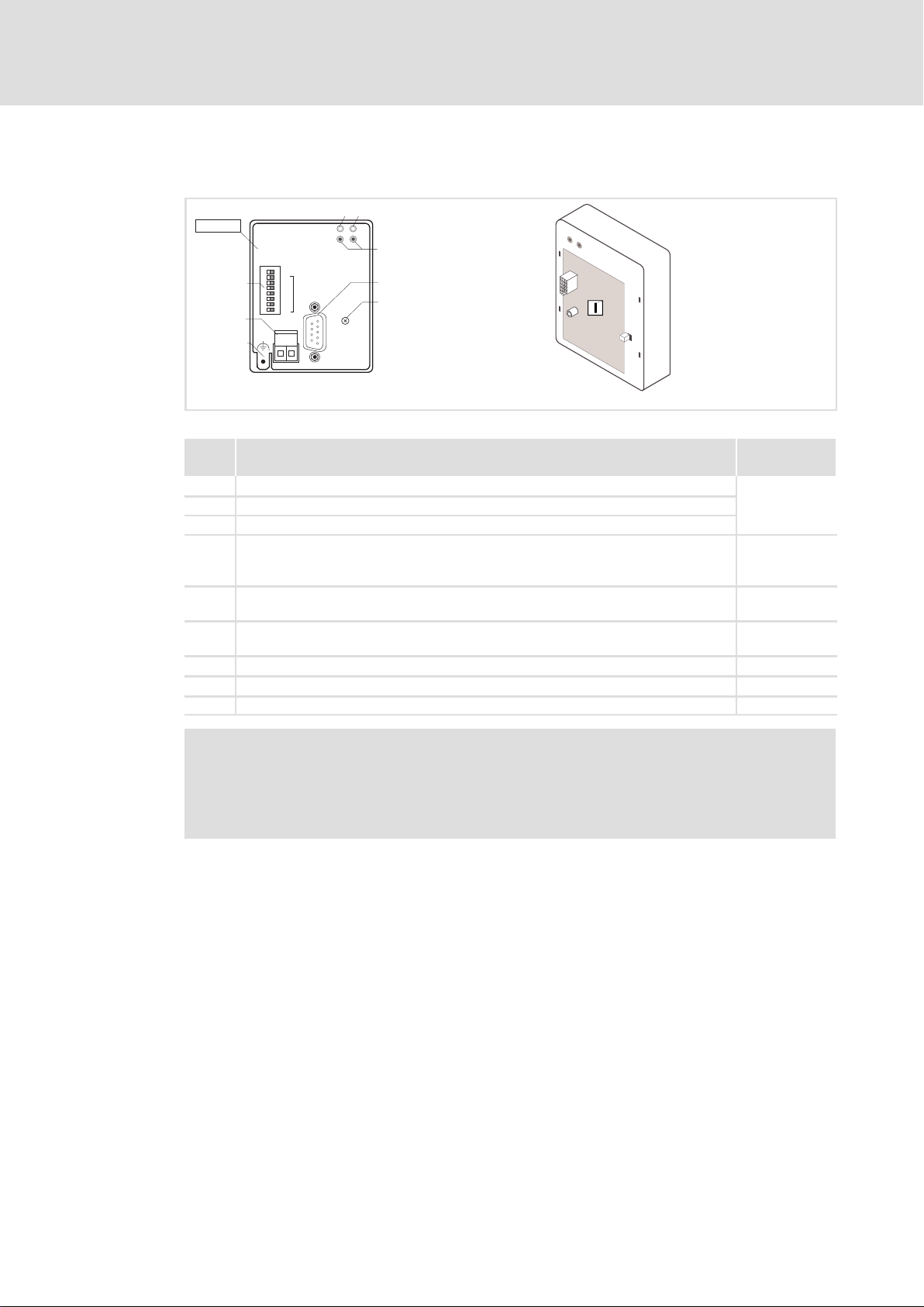
4.4 Dimensions
8
4
2
1
_
Adresse
L
PROFIBUS DP
2133
ONOFF
2131
8
7
64
32
b
16
123456
24V DC
+
a
a61 mm
b 75 mm
e 28 mm
e1 18 mm
18
e1
e
2133PFB003
20
l
EDSMF2133IB EN 5.0
Page 21

5 Installation
} Danger!
Inappropriate handling of the communication module and the standard device
can cause serious personal injury and material damage.
Observe the safety instructions and residual hazards described in the
documentation for the standard device.
( Stop!
Electrostatic discharge
Electronic components of the communication module can be damaged or
destroyed through electrostatic discharge.
Possible consequences:
ƒ The communication module is damaged.
ƒ Fieldbus communication is not possible or faulty.
Protective measures
ƒ Discharge electrostatic charges before touching the module.
Installation 5
EDSMF2133IB EN 5.0
l
21
Page 22
5
5.1 Mechanical installation
Installation
Mechanical installation
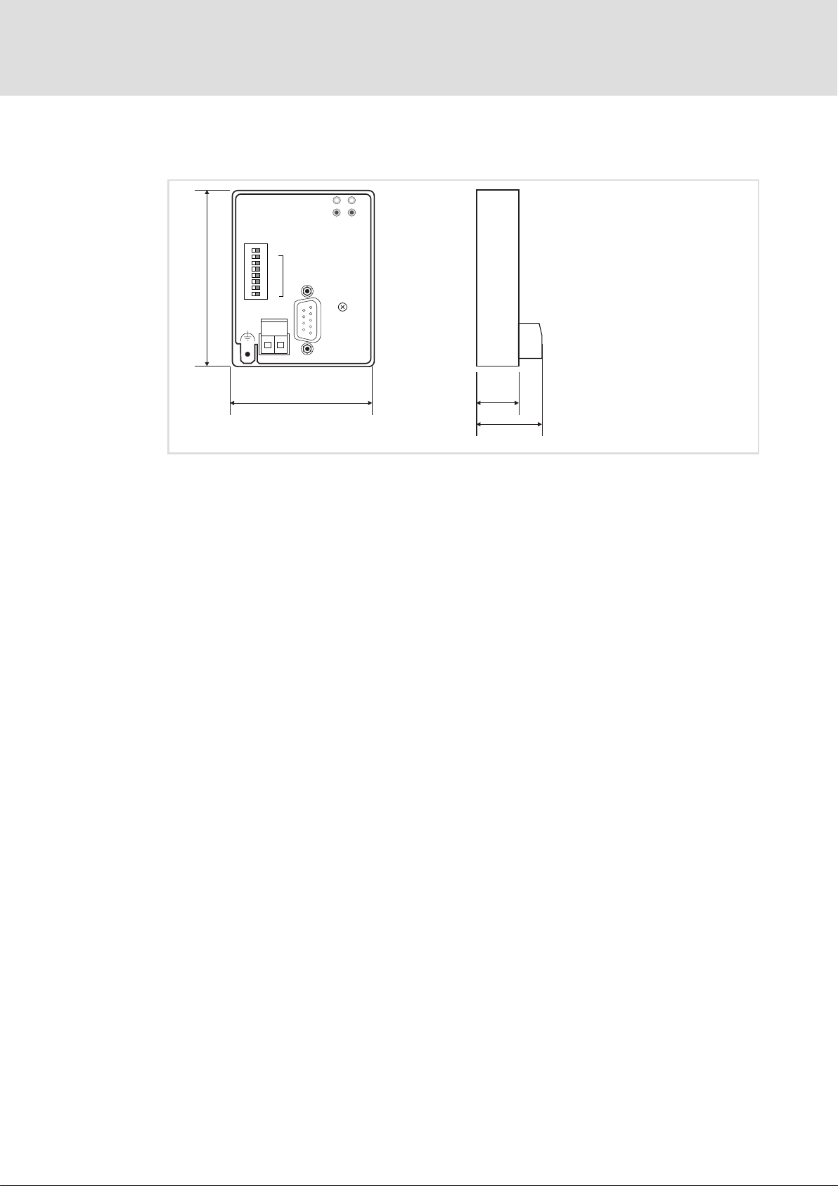
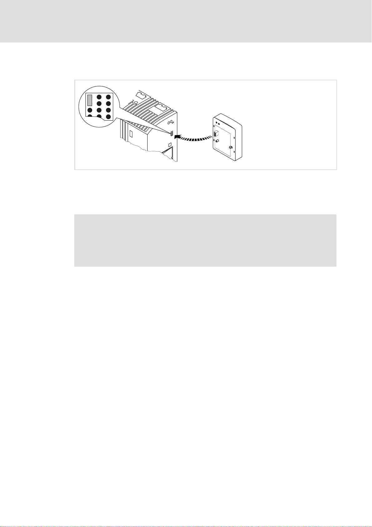
Fig. 5−1 Attaching the communication module
ƒ Plug the communication module onto the standard device (here: 8200 vector).
ƒ Tighten the communication module to the standard device using the fixing screw in
order to ensure a good PE connection.
2102LEC014
) Note!
For the internal supply of the communication module by the 8200 vector
frequency inverter the jumper has to be adjusted within the interface opening
(see illustration above).
Observe the notes (¶ 28).
22
l
EDSMF2133IB EN 5.0
Page 23

Wiring according to EMC (CE−typical drive system)
5.2 Electrical installation
5.2.1 Wiring according to EMC (CE−typical drive system)
For wiring according to EMC requirements observe the following points:
) Note!
ƒ Separate control cables/data lines from motor cables.
ƒ Connect the shields of control cables/data lines at both ends in the case of
digital signals.
ƒ Use an equalizing conductor with a cross−section of at least 16mm
(reference:PE) to avoid potential differences between the bus nodes.
ƒ Observe the other notes concerning EMC−compliant wiring given in the
documentation for the standard device.
Wiring procedure
Installation
Electrical installation
5
2
1. Comply with bus topology, thus do not use stubs.
2. Observe notes and wiring instructions in the documents for the control system.
3. Only use cables that comply with the given specifications (¶ 25).
4. Observe notes for the voltage supply of the module (¶ 28).
5. Activate the bus terminating resistors on the first and last physical bus device
(¶ 24).
6. Adapt baud rate to the bus cable length.
EDSMF2133IB EN 5.0
l
23
Page 24
5
Installation
Electrical installation
Wiring with a host (master)
5.2.2 Wiring with a host (master)
{ Danger!
You have to provide additional electrical isolation if ...
ƒ an 820X and 821X controller is connected to the host and
ƒ a safe electrical isolation (reinforced insulation) according to EN 61800−5−1
is required.
Basic wiring of the PROFIBUS
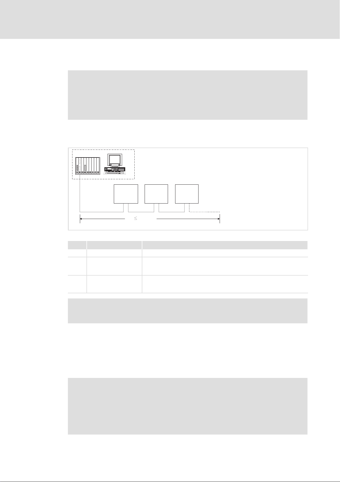
The connection of the PROFIBUS bus system is shown in the general layout drawing.
1
333
GG + 2133 GG + 2133 GG + 2133
222
0m
Fig. 5−2 Example: PROFIBUS with RS485 wiring (without repeater)
1200 m
E82ZAFP005
No. Element Comment
1 Host e.g. PC or PLC with PROFIBUS master interface module
2 Bus cable Connects the PROFIBUS master interface module to the communication
modules.
l The baud rate depends on the bus cable length (^ 26).
3 PROFIBUS slave Applicable standard device (GG, ^ 12) with communication module
l Activate the bus terminating resistors on the first and last physical bus
device (^ 24).
) Note!
When using a repeater, max. 125 devices can communicate via the PROFIBUS.
Bus terminating resistor
The PROFIBUS must be terminated by a bus terminating resistor at the physically first and
last station.
The bus terminating resistor is in the bus connector (¶ 128)and is activated using a
switch.
) Note!
ƒ If you want to disconnect individual bus devices, ensure that the bus
terminators at the cable ends remain active.
ƒ Please note that the bus termination is no longer active if ...
– the connector has been disconnected e.g. in service case;
– the voltage supply of the communication module has been switched off.
24
l
EDSMF2133IB EN 5.0
Page 25
Installation
Electrical installation
Wiring with a host (master)
Number of bus devices
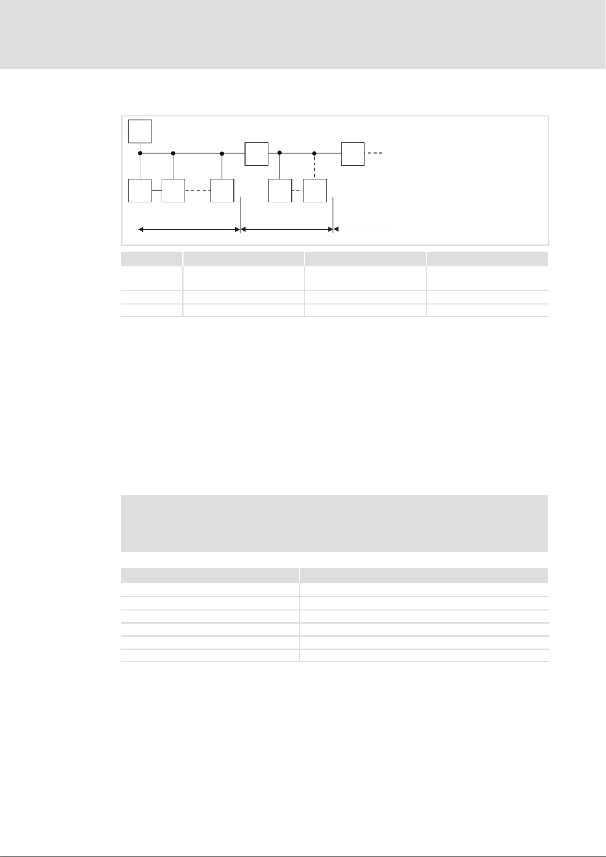
M
RR
SS S S S
123
Segment Master (M) Slave (S) Repeater (R)
11231
30
2 − 30 1
3 − 30 1
−
−
5
2133PFB004
I Tip!
Repeaters do not have a device address. When calculating the maximum
number of bus devices, they reduce the number of devices by 1 on each side of
the segment.
Repeaters can be used to build up line and tree topologies. The maximum total
bus system expansion depends on ...
ƒ the baud rate used;
ƒ the number of repeaters used.
Specification of the transmission cable
) Note!
Only use cables complying with the listed specifications of the PROFIBUS user
organisation.
Field Values
Specific resistance 135 ... 165 /km, (f = 3 ... 20 MHz)
Capacitance per unit length 30 nF/km
Loop resistance < 110 /km
Core diameter > 0.64 mm
Core cross−section > 0.34 mm
Cores Twisted double, insulated and shielded
2
EDSMF2133IB EN 5.0
l
25
Page 26

5
Installation
Electrical installation
Wiring with a host (master)
Bus cable length
The length of the bus cable depends on the baud rate used:
Baud rate [kbps] Length [m]
9.6 ... 93.75 1200
187.5 1000
500 400
1500 200
3000 ... 12000 100
) Note!
The baud rate depending on the data volume, cycle time, and number of nodes
should only be selected as high as required for the application.
I Tip!
For high baud rates we recommend to consider the use of optical fibres.
Advantages of optical fibres:
ƒ On the transmission path external electromagnetic interference remains
ineffective.
ƒ Bus lengths of several kilometres are also possible with higher baud rates.
The bus length
– is irrespective of the baud rate.
– depends on the optical fibre used.
26
l
EDSMF2133IB EN 5.0
Page 27

Installation
Electrical installation
Connection of the PROFIBUS
5
5.2.3 Connection of the PROFIBUS
The PROFIBUS network is connected via the 9−pole Sub−D socket.
View Pin Designation Description
1 − −
2 − −
9
6
5
1
3 RxD/TxD−P Data cable B (receive / send data plus)
4 RTS Request To Send
5 M5V2 Data reference potential (ground to 5V)
6 P5V2 5 V DC / 30 mA (bus termination)
7 − −
8 RxD/TxD−N Data cable A (receive / send data minus)
9 − −
(receive / send data, no differential signal)
EDSMF2133IB EN 5.0
l
27
Page 28
5
Installation
Electrical installation
Voltage supply
5.2.4 Voltage supply
Internal voltage supply
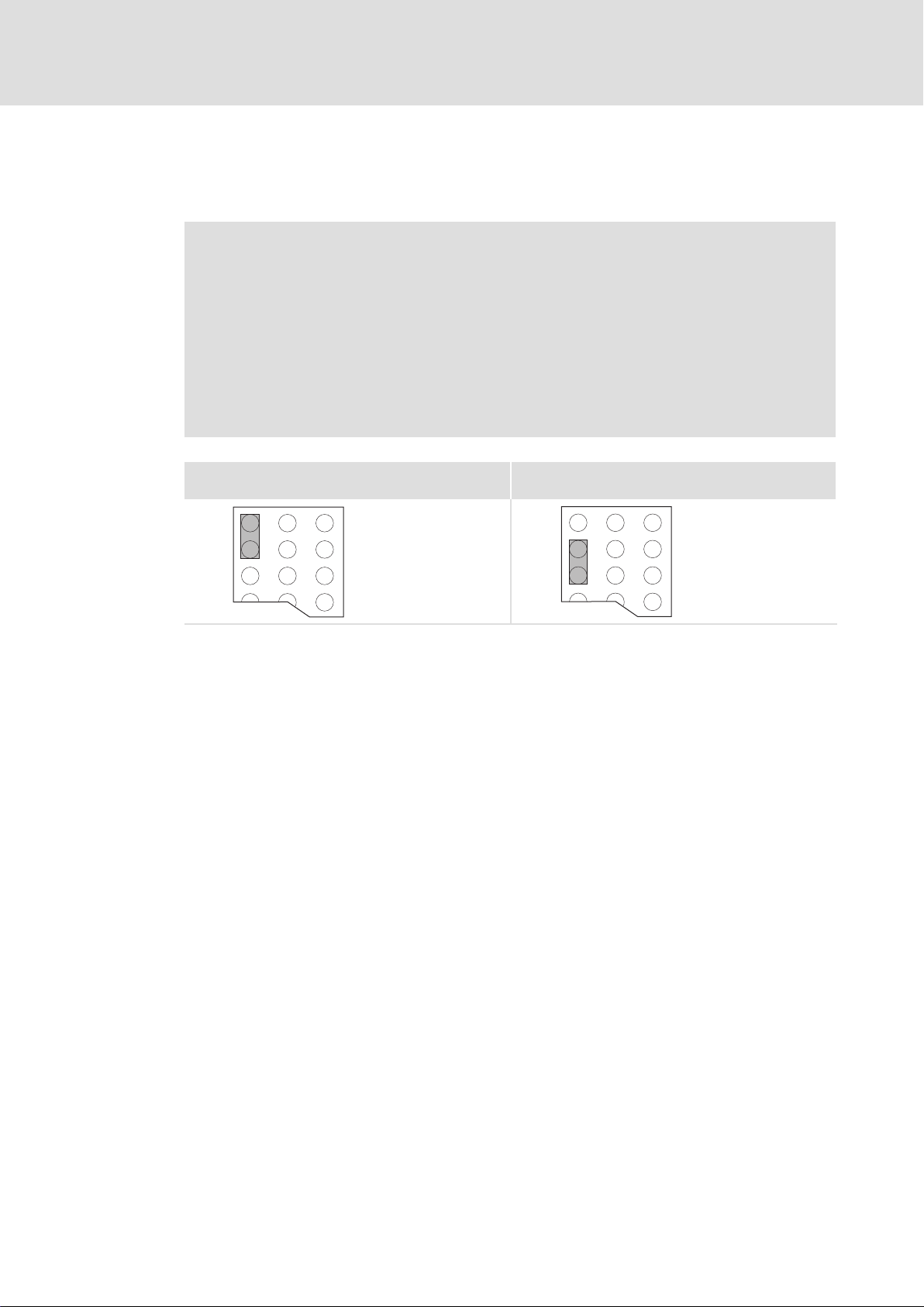
) Note!
Internal voltage supply has been selected in the case of standard devices with
an extended AIF interface opening (e.g. front of 8200 vector). The area shown
on a grey background in the graphic marks the jumper position.
ƒ By default, this is not supplied internally in the standard device.
ƒ For internal voltage supply place the jumper on the position indicated
below.
In the case of all other device series (9300, ECS), voltage is always supplied
from the standard device.
(Only external voltage supply possible.)
Lenze setting
Internal voltage supply
28
l
EDSMF2133IB EN 5.0
Page 29

Installation
Electrical installation
Voltage supply
External voltage supply
) Note!
Always use a separate power supply unit in every control cabinet and safely
separate it according to EN 61800−5−1 ("SELV"/"PELV") in the case of external
voltage supply and larger distances between the control cabinets.
External voltage supply of the communication module is required if communication via
the fieldbus is to be maintained even when the power supply of the standard device fails.
) Note!
With external voltage supply of the communication module, the active bus
terminating resistor is fed independently of the operation of the basic device.
Thus the bus system remains active even if the basic device is switched off or
fails.
5
Plug connector Explanation
"+" V = 24VDC (21.6 V − 0% ... 26.4 V + 0 %)
I = 120 mA
"−" Reference potential for external voltage supply
Controller External voltage supply
820X Always required
821X / 822X / 824X /
93XX / 9300 Servo PLC /
Drive PLC / ECSxS /
ECSxP / ECSxA
8200 vector See notes given in "Internal voltage supply" ^ 28
Only required if the mains supplying the corresponding controller is to be switched off
but communication must not be interrupted.
For these basic devices the internal voltage supply can be used.
EDSMF2133IB EN 5.0
l
29
Page 30

5
Installation
Electrical installation
Cable cross−sections and screw−tightening torques
5.2.5 Cable cross−sections and screw−tightening torques
Area Values
Electrical connection Plug connector with screw connection
Possible connections
Tightening torque 0.5 ... 0.6 Nm (4.4 ... 5.3 lb−in)
Stripping length 6 mm
rigid:
1.5 mm
flexible:
without wire end ferrule
1.5 mm
with wire end ferrule, without plastic sleeve
1.5 mm
with wire end ferrule, with plastic sleeve
1.5 mm
2
(AWG 16)
2
(AWG 16)
2
(AWG 16)
2
(AWG 16)
30
l
EDSMF2133IB EN 5.0
Page 31

6 Commissioning
During commissioning, system−dependent data as e.g. motor parameters, operating
parameters, responses and parameters for fieldbus communication are selected for the
controller.
In Lenze devices, this is done via codes. The codes are stored in numerically ascending order
in the Lenze controllers and in the plugged−in communication/function modules.
In addition to these configuration codes, there are codes for diagnosing and monitoring
the bus devices.
The codes can be set e.g. via an operating module (keypad) or a PC with the Lenze
parameter setting program »Global Drive Control« (GDC).
6.1 Before switching on
Commissioning
Before switching on
6
( Stop!
Prior to switching on the mains voltage, check the wiring for completeness,
short−circuit and earth fault.
EDSMF2133IB EN 5.0
l 31
Page 32

6
Commissioning
Initial switch−on
6.2 Initial switch−on
) Note!
) Note!
Step−by−step commissioning of the communication module with DRIVECOM device
control is described below.
Step Procedure Detailed
1. Select process data communication with DRIVECOM profile in the
2. Configure host system for communication with the EMF2133IB
3. Inhibit standard device via terminal. Documentation of
4. Check bus termination.
5. Provide software compatibility with the communication module.
6. Drive−specific settings. Documentation of
7. Prepare controller for communication. ^ 38
8. Switch on the mains voltage for the controller and, if available, the separate
9. A Set station address via ...
ECS servo system
ECS devices cannot be used with the DRIVECOM or PROFIdrive control.
Manual settings are not required for the baud rate. The communication
module is automatically adjusted to the baud rate of the master.
information
configuration software of the PROFIBUS master.
Example: "Par(kons)+3PZD"
^ 34
communication module.
the standard device
^ 37
l The PROFIBUS must be terminated by a bus terminating resistor at the
physically first and last station.
l The bus terminating resistor is integrated into the bus connector and can
be activated via a switch.
^ 37
l 2133: DIP switch S8 = OFF
l 2131: DIP switch S8 = ON (with this setting, continue commissioning for
the EMF2131IB communication module.)
Lenze setting: S8 = OFF
the standard device
^ 44
voltage supply for the communication module.
Response
The green bus LED on the front of the communication module comes on.
^ 42
– Standard device code C0009,
– DIP switch S1 ... S7 or
– define through a master (class 2).
l In the PROFIBUS network, every station needs its own address.
l Valid address range: 3 ... 126
l If the settings via code apply (DIP switches S1 ... S7 = OFF), the address has
to be newly assigned after a parameter set transfer.
l The address modified via keypad becomes effective immediately.
B Switch off the voltage supply of the function module and the standard
device and then switch it on again to accept the changed settings.
10. Manual settings are not required for the baud rate. The communication
module is automatically adjusted to the baud rate of the master.
l 32
EDSMF2133IB EN 5.0
Page 33

Commissioning
Initial switch−on
6
ProcedureStep
11. It is now possible to communicate with the controller, i.e.
l exchange process data (setpoints and actual values);
l read all codes;
l change all codes that can be written.
See the attribute table or code description of the corresponding standard
device.
Response
The yellow LED on the communication module is blinking when the PROFIBUS
is active.
12. Enable standard device via terminal. Documentation of
Detailed
information
the standard device
EDSMF2133IB EN 5.0
l 33
Page 34

6
Commissioning
Configuring the host system (master)
6.3 Configuring the host system (master)
The host must be configured before communication with the communication module is
possible.
Master settings
For configuring the PROFIBUS, the device data base file (GSE file) of the communication
module has to be imported into the configuring software of the master.
I Tip!
The GSE file can be downloaded in the "Services & Downloads" area at
www.Lenze.com.
Device data base file (GSE)
The following configurations can be found in the device data base files Lenz2133.GSD
(DP−V0) and Len_2133.GSD (DP−V1):
ƒ Device control and DP−V0 parameter data channel
Selection text in Lenz2133.GSE Parameter data Process data
without
consistency
PAR(cons.)+PZD(nwordsI/O)AR
PAR(cons.)+PZD(nwordscon)AR
PAR + PZD(n words I/O) AR
PAR + PZD(n words con) AR
PZD(n words I/O) AR
PZD(n words cons.) AR
n = 1 ... 12
Without parameter data channel
Assigned I/O
with consistency without
consistency
n words
n words
n words
with consistency
n words
n words
n words
memory
4 + n words
4 + n words
4 + n words
4 + n words
n words
n words
ƒ DRIVECOM control and DP−V0 parameter data channels
Selection text in Lenz2133.GSE Parameter data Process data
PAR(cons.) + PZD(n words I/O)
PAR(cons.) + PZD(n words cons.)
PAR + PZD(n words I/O)
PAR + PZD(n words cons.)
PZD(n words I/O)
PZD(n words cons.)
n = 1 ... 12
without
consistency
Without parameter data channel
with consistency without
consistency
n words
n words
n words
with consistency
n words
n words
n words
Assigned I/O
memory
4 + n words
4 + n words
4 + n words
4 + n words
n words
n words
l 34
EDSMF2133IB EN 5.0
Page 35

Configuring the host system (master)
ƒ POFIdrive control and DP−V1 parameter data channel
Commissioning
6
Selection text in Len_2133.GSE Parameter data Process data
PPO1
PPO2
PPO5
PPO3
PPO4
PPO1 (process data consistency)
PPO2 (process data consistency)
PPO5 (process data consistency)
PPO3 (process data consistency)
PPO4 (process data consistency)
n = 1 ... 12
without
consistency
Without parameter data channel
Without parameter data channel
with consistency without
consistency
2 words
6 words
10 words
2 words
6 words
Example of the selection text of the device data base file
PAR (Cons) + PCD (7W) AR
Lenze device control
Process data words
(7 words)
Parameter data channel
(4 bytes consistent)
PAR (Cons) + PCD (8W)
Without "AR": Control with DRIVECOM−Profil
Process data words
(8 words)
Parameter data channel
(4 bytes consistent)
with consistency
2 words
6 words
10 words
2 words
6 words
Assigned I/O
memory
6 words
10 words
14 words
2 words
6 words
6 words
10 words
14 words
2 words
6 words
) Note!
Use overall consistency
ƒ We recommend to exclusively use configurations with consistency for the
parameter data channel to avoid data conflicts between the PROFIBUS
master and the host CPU.
ƒ Please note that the processing of consistent data varies between hosts.
This must be considered in the PROFIBUS application program.
ƒ Detailed information on consistency can be found on ^ 110.
EDSMF2133IB EN 5.0
l 35
Page 36

6
Commissioning
Configuring the host system (master)
Defining the user data length
The user data length is defined during the initialisation phase (configuration). Up to 12
process data words can be configured (depending on the basic device used).
Optionally you can activate the parameter data channel. If the parameter data channel is
active, it additionally occupies 4 words of the process data inputs and outputs.
ƒ PIW: Process data input word (process data from the controller to the master)
ƒ POW: Process data output word (process data from the master to the controller)
The user data lengths for process input data and process output data are identical. The
selection takes place via identification bytes in the configuration software for the
PROFIBUS system.
Parameter data channel Process data channel
Without /
with
Without −
With
General structure of the identification byte
MSB LSB
7 6 5 4 3 2 1 0
Identification / user data length Identification / user data length
l Identification
l Identification
– without consistency: 73
(115)
– with consistency: F3
l User data length: 4 words
(Word rt 1 ... word 4)
hex
hex
(243)
– without consistency: 70
– with consistency: F0
l User data length: 1 ... 12 words
(PAW1/PEW1 ... PAW12/PEW12)
l Identification
– without consistency: 70
– with consistency: F0
l User data length: 1 ... 12 words
(PAW1/PEW1 ... PAW12/PEW12)
hex
hex
hex
... FB
hex
... FB
... 7B
hex
(240 ... 251)
hex
... 7B
hex
(240 ... 251)
hex
(112 ... 123)
(112 ... 123)
User data length
00 1 byte or 1 word
...
15 16 bytes or 16 words
Input/Output
00 Specific identification format
01 Input
10 Output
11 Input and output
Length/Format
0 Byte
1 Word
Consistency
0 Byte or word
1 Total length
l 36
EDSMF2133IB EN 5.0
Page 37

Commissioning
Activating the bus terminating resistor
6
6.4 Activating the bus terminating resistor
Bus terminating resistor
The PROFIBUS must be terminated by a bus terminating resistor at the physically first and
last station.
The bus terminating resistor is in the bus connector (¶ 128)and is activated using a
switch.
) Note!
ƒ If you want to disconnect individual bus devices, ensure that the bus
terminators at the cable ends remain active.
ƒ Please note that the bus termination is no longer active if ...
– the connector has been disconnected e.g. in service case;
– the voltage supply of the communication module has been switched off.
6.5 Setting the software compatibility
) Note!
If the EMF2131IB communication module is replaced by the EMF2133IB
communication module, ...
ƒ do not change any host settings;
ƒ set the DIP switch S8 to the "ON" position.
EDSMF2133IB EN 5.0
l 37
Page 38

6
Commissioning
Preparing the standard device for communication
Frequency inverter 82XX / 8200 vector
6.6 Preparing the standard device for communication
6.6.1 Frequency inverter 82XX / 8200 vector
Step Procedure Detailed
1.
2. Terminal 28 (RFR = controller enable) is always active and must be set to HIGH
3. The controller can now accept control and parameter setting data via the
4. Select speed setpoint unequal to 0. ^ 47
5. Change to status "READY TO SWITCH ON".
6. Wait for status "READY TO START" to be reached.
7. Change to the "OPERATION ENABLED" state.
8. Wait for "OPERATION ENABLED". ^ 68
In order that you can operate the controller via PROFIBUS, set the Lenze
parameter "Operating mode" C0001 = 3.
Example of PROFIBUS Write:
l C0001=3
l Index = 0x5FFE (resulting from 0x5FFF − C0001
l Subindex: 0
l Value: 30000 (resulting from 3 x 10
level during PROFIBUS operation. Otherwise the controller cannot be enabled
by PROFIBUS (DRIVECOM device status "OPERATION ENABLED").
Note
In case of 821X, 822X and 8200 vector, the quick stop function (QSP) is always
active. If QSP is configured to an input terminal (Lenze setting: Not assigned),
it has to be on HIGH level during PROFIBUS operation.
PROFIBUS.
Select value for DRIVECOM control word:
0b0000 0000 0111 1110 (0x007E).
Value for DRIVECOM status word:
0bxxxx xxxx x01x 0001.
Select value for DRIVECOM control word:
0b0000 0000 0111 1111 (0x007F)
4
)
hex
information
^ 46
Documentation of
the standard device
)
l 38
EDSMF2133IB EN 5.0
Page 39

Commissioning
Preparing the standard device for communication
93XX servo inverter / 9300 Servo PLC
6
6.6.2 93XX servo inverter / 9300 Servo PLC
Step Procedure Detailed
1.
2.
3. The controller can now accept control and parameter setting data via the
4. Select speed setpoint unequal to 0. ^ 47
5. Change to status "READY TO SWITCH ON".
6. Wait for status "READY TO START" to be reached.
7. Change to the "OPERATION ENABLED" state.
8. Wait for "OPERATION ENABLED". ^ 68
93XX
9300
servo
PLC
Terminal 28 (RFR = controller enable) is always active and must be set to HIGH
level during PROFIBUS operation. Otherwise the controller cannot be enabled
by PROFIBUS (DRIVECOM device status "OPERATION ENABLED").
Note
l For the signal configuration C0005 = 1013 (speed control), the quick stop
l With the signal configuration C0005 = xx13, the terminal A1 is switched as
PROFIBUS.
Select value for DRIVECOM control word:
0b0000 0000 0111 1110 (0x007E).
Value for DRIVECOM status word:
0bxxxx xxxx x01x 0001.
Select value for DRIVECOM control word:
0b0000 0000 0111 1111 (0x007F)
In order that you can operate the controller via PROFIBUS, set the
Lenze parameter "Signal configuration" C0005 = xxx3.
l When commissioning for the first time, we recommend to select
the signal configuration "1013" (speed control).
Example of PROFIBUS Write:
l C0005=1013 (speed control)
l Index = 0x5FFA (resulting from 0x5FFF − C0005
l Subindex: 0
l Value: 10130000 (resulting from 1013 x 10
Implement the system blocks AIF−IN1...3, AIF−OUT1 ... 3 and, if
available, the AIF management into the control configuration of the
IEC61131 project.
function (QSP) in connection with the right/left change−over is assigned to
the digital input terminals E1 and E2 and thus always active. For PROFIBUS
operation, E1 must be assigned to HIGH level.
voltage output. This means that only the following terminals should be
connected:
– X5.A1 with X5.28 (RFR)
– X5.A1 with X5.E1 (CW/QSP)
information
^ 46
Documentation of
the standard device
)
hex
4
)
EDSMF2133IB EN 5.0
l 39
Page 40

6
Commissioning
Preparing the standard device for communication
Drive PLC
6.6.3 Drive PLC
Step Procedure Detailed
1. Implement the system blocks AIF−IN1...3, AIF−OUT1 ... 3 and, if available, the
2. The controller can now accept control and parameter setting data via the
3. Select speed setpoint unequal to 0. ^ 47
4. Change to status "READY TO SWITCH ON".
5. Wait for status "READY TO START" to be reached.
6. Change to the "OPERATION ENABLED" state.
7. Wait for "OPERATION ENABLED". ^ 68
AIF management into the control configuration of the IEC61131 project.
PROFIBUS.
Select value for DRIVECOM control word:
0b0000 0000 0111 1110 (0x007E).
Value for DRIVECOM status word:
0bxxxx xxxx x01x 0001.
Select value for DRIVECOM control word:
0b0000 0000 0111 1111 (0x007F)
information
^ 46
Documentation of
the standard device
l 40
EDSMF2133IB EN 5.0
Page 41

Commissioning
Preparing the standard device for communication
Axis modules ECSxS / ECSxA
6
6.6.4 Axis modules ECSxS / ECSxA
Step Procedure Detailed
1.
2. The terminals SI1 (controller enable) and SI2 (pulse inhibit) are always active
3. The controller can now accept control and parameter setting data via the
ECSxS
ECSxA Implement the system blocks AIF−IN1...3, AIF−OUT1 ... 3 and, if
and must be assigned to HIGH level during PROFIBUS operation. Otherwise
the controller cannot be enabled by PROFIBUS.
PROFIBUS.
Set the Lenze parameter "Control mode":
l C3005 = 1003 (setpoint via AIF, speed−controlled)
l C3005 = 4003 (setpoint via AIF, torque−controlled)
Example of PROFIBUS Write:
l C3005=1003 (speed control)
l Index = 0x5442 (resulting from 0x5FFF − C3005
l Subindex: 0
l Value: 10030000 (resulting from 1003 x 10
available, the AIF management into the control configuration of the
IEC61131 project.
) Note!
ECS servo system
ECS devices cannot be used with the DRIVECOM or PROFIdrive control.
information
^ 46
Documentation of
the standard device
)
hex
4
)
EDSMF2133IB EN 5.0
l 41
Page 42

6
Commissioning
Setting the node address
Setting via code
6.7 Setting the node address
) Note!
ƒ The addresses of all controllers connected to the network must differ from
each other.
ƒ If the DIP switches S1 ... S7 are in the OFF position, the code setting for the
station address is active (Lenze setting).
ƒ Switch off the voltage supply of the function module and the controller and
then switch it on again to activate the changed settings.
The setting of the station address can be freely selected ...
ƒ via the front DIP switches S1 ... S7;
ƒ via the standard device code C0009;
ƒ through a master (class 2).
Valid address range: 3 … 126
(Lenze setting: 126, provided that C0009 = 1)
6.7.1 Setting via code
ƒ DIP switches S1 ... S7 = OFF (Lenze setting)
ƒ Set the node address via the standard device code C0009 (e.g. via keypad or »Global
Drive Control« (GDC)).
6.7.2 Settings via DIP switch
Set the node address with the DIP switches S1 ... S7.
The sum of valencies makes the station address to be set:
DIP switch Valency Example
S1 1 ON
S2 2 OFF
S3 4 OFF
S4 8 OFF
S5 16 ON
S6 32 ON
S7 64 ON
Switch position Node address
1 + 16 + 32 + 64 = 113
l 42
EDSMF2133IB EN 5.0
Page 43

6.7.3 Settings by a master (class 2)
ƒ With this method only one device must be connected to the bus. This can be
achieved by a special switch−on sequence.
ƒ In the "Power On" status, the master (class 2) can set a device address via the
"Set_Slave_Address" telegram.
ƒ Settings made through the master (class 2 only) have an effect on the setting in
standard device code C0009.
PROFIBUS station address Mapping to code C0009
1 ... 2 No (master addresses)
3 ... 99 Yes (3 ... 99)
100 ... 125 Yes (C0009 = 2)
126 (LENZE setting) Yes (C0009 = 1)
Tab. 6−1 Assignment of station addresses to controllers
Commissioning
Setting the node address
Settings by a master (class 2)
6
EDSMF2133IB EN 5.0
l 43
Page 44

6
Commissioning
Connecting the mains voltage
Settings by a master (class 2)
6.8 Connecting the mains voltage
) Note!
If you use the external voltage supply for the communication module, please
switch it on.
The following LEDs at the front of the communication module must be on:
ƒ The top green LED (Status display of voltage supply)
ƒ The bottom green LED (status display of standard device)
Protection against uncontrolled restart
) Note!
Establishing communication
If communication is to be established via an externally supplied
communication module, initially the standard device must also be switched
on.
After communication has been established, the externally supplied module is
independent of the power on/off state of the standard device.
Protection against uncontrolled restart
After a fault (e.g. short−term mains failure), a restart of the drive is not always
wanted and − in some cases − even not allowed.
The restart behaviour of the controller can be set in C0142:
ƒ C0142 = 0 (Lenze setting)
– The controller remains inhibited (even if the fault is no longer active).
– The drive starts up in a controlled manner by explicit controller enable:
93XX: Set terminal 28 to HIGH level.
ECSXX: Set terminals X6/SI1 and X6/SI2 to HIGH level.
ƒ C0142 = 1
– An uncontrolled restart of the drive is possible.
l 44
EDSMF2133IB EN 5.0
Page 45

7 Process data transfer
request
response
Process data transfer 7
2133PFB008
Fig. 7−1 PROFIBUS process data transfer
PROFIBUS transmits parameter data and process data between the host (master) and the
controllers connected to the bus (slaves). Depending on their time−critical nature, the data
are transmitted via different communication channels.
ƒ Process data are transmitted via the process data channel.
ƒ Process data serve to control the drive controller.
ƒ The transmission of process data is time−critical.
ƒ Process data are cyclically transferred between the host and the controllers
(continuous exchange of current input and output data).
ƒ The host can directly access the process data. In the PLC, for instance, the data are
directly assigned to the I/O area.
ƒ With the function module a maximum of 10 process data words (16 bits/word) can
be exchanged in each direction.
ƒ Process data are not stored in the controller.
ƒ Process data are, for instance, setpoints, actual values, control words and status
words.
EDSMF2133IB EN 5.0
) Note!
Observe the direction of the information flow!
ƒ Process input data (Rx data):
– Process data from controller (slave) to host (master)
ƒ Process output data (Tx data):
– Process data from host (master) to controller (slave)
l
45
Page 46

7
7.1 Lenze device control
7.1.1 Setpoint source selection
Process data transfer
Lenze device control
Setpoint source selection
) Note!
Note that the selection of the setpoint source must be set the same in all
parameter sets.
82XX / 8200 vector frequency inverters
For these controllers the setpoint source selection is determined under code C0001. An
evaluation of process data is only possible if code C0001 is set to "3" when the controller
is operated together with the communication module (selection: Process data channel of
a communication module). The process data channel which defines the frequency setpoint
(mapping to C0046) is the setpoint source and the control word (C0135).
In case of the 8200 vector, the assignment of the setpoint source to the corresponding
analog signal can be checked or changed in code C0412.
93XX controller
For operation via PROFIBUS, code C0005 must be set to the value "xxx3" (x = wildcard for
selected preconfiguration).
Example: C0005 = 1013: "Speed control" preconfiguration
ECSxS axis module
For operation via the PROFIBUS, code C3005 "Control mode" must be set:
ƒ C3005 = 1003 (setpoint via AIF, speed−controlled)
ƒ C3005 = 4003 (setpoint via AIF, torque−controlled)
Servo PLC 9300 / Drive PLC / ECSxA
Operation via the PROFIBUS requires that the system blocks AIF−IN1...3, AIF−OUT1 ... 3
and, if available, the AIF management are part of the control configuration of the IEC61131
project.
ƒ For cyclic process data telegrams to the drive , the AIF−IN1...3 system blocks are
used. The control word (byte 1 and byte 2) contained in a process data telegram is
further processed via these system blocks in the standard device.
ƒ For cyclic process data telegrams from the drive , the system blocks AIF−OUT1...3 are
used. The status word (byte 1 and byte 2) contained in the process data telegram is
transmitted to the master via these system blocks .
46
l
EDSMF2133IB EN 5.0
Page 47

Process data transfer
Lenze device control
Process data signals for 82XX frequency inverters
7
7.1.2 Process data signals for 82XX frequency inverters
Process data telegram from drive
Byte 1 Byte 2 Byte 3 Byte 4
Status word Actual value
High byte Low byte High byte Low byte
) Note!
ƒ Frequency and speed values are scaled with
24000 480 Hz.
ƒ Torque values are scaled with 16384 100%.
EDSMF2133IB EN 5.0
l
47
Page 48

7
Process data transfer
Lenze device control
Process data signals for 82XX frequency inverters
Device status word AIF−STAT for 82XX (C0150, I−5F69)
820X 821X / 822X / 824X
Bit Assignment Bit Assignment
0
Current parameter set
01Parameter set 1 or 3 active
Parameter set 2 or 4 active
1 Pulse inhibit (IMP)
01Pulses for power stage enabled
Pulses for power stage inhibited
2
I
(current limit reached)
max
01Current limit not reached
Current limit reached
3 Not assigned 3
4
5
6
7
fd = f
01fd f
01Qmin not active
dset
dset
fd = f
dset
Qmin (fd f
Qmin active
dQmin
fd = 0 (actual frequency value = 0)
01fd 0
f
= 0
d
Controller inhibit (CINH))
01No controller inhibit
Controller inhibit active
)
8 ... 11 Device status 8 ... 11 Device status
Bit 11 10 9 8 Bit 11 10 9 8
0 0 0 0 Device initialisation 0 0 0 0 Device initialisation
1
0 0 0 Active fault 0 0 1 0 Switch−on inhibit
12
13
14
15
Overtemperature warning
01No warning
Warning
U
(DC bus overvoltage)
Gmax
01No overvoltage
Overvoltage
Direction of rotation
01CW rotation
CCW rotation
Ready for operation
01Not ready for operation
Ready for operation
0
1
2
4
5
6
7
12
13
14
15
Current parameter set
01Parameter set 1 or 3 active
Parameter set 2 or 4 active
Pulse inhibit (IMP)
01Pulses for power stage enabled
Pulses for power stage inhibited
I
(current limit reached)
max
01Current limit not reached
Current limit reached
fd = f
fd = f
dset
dset
dset
01fd f
Ramp function generator (RFG) on/off
01RFG−On RFG−Off
RFG on = RFG off
Qmin (f
f
d
01Qmin not active
Qmin active
fd = 0 (actual frequency value = 0)
01fd 0
f
= 0
d
Controller inhibit (CINH))
01No controller inhibit
Controller inhibit active
0 0 1 1 Operation inhibited
1 0 0 Flying restart circuit active
0
0
1 0 1 DC injection brake active
1 1 0 Operation enabled
0
0
1 1 1 Message active
0 0 0 Active fault
1
1 1 1 Communication with standard
1
Overtemperature warning
01No warning
Warning
U
(DC bus overvoltage)
Gmax
01No overvoltage
Overvoltage
Direction of rotation
01CW rotation
CCW rotation
Ready for operation
01Not ready for operation
Ready for operation
dQmin
)
device not possible
48
l
EDSMF2133IB EN 5.0
Page 49

Process data transfer
Lenze device control
Process data signals for 82XX frequency inverters
7
.B0
.B1
.B2
.B3
.B4
.B5
.B6
.B7
.B8
.B9
.B10
.B11
.B12
.B13
.B14
.B15
16 Bit
AIF
16 Bit
- / fd=fdsoll
fd=fdsoll / HLG
B11 B10 B9 B8
0
0
0
1
0
0
1
0
0
.
.
.
.
.
.
.
.
.
.
.
.
.
.
.
.
.
.
PAR
IMP
Imax
Qmin
fd>0
RSP
STAT
0
0
2
0
3
1
.
.
.
.
.
.
Ugmax
R/L
RDY
C0050
.
.
.
.
.
.
T
ü
Fig. 7−2 Read access to status word and actual frequency in 82XX (fixed assignment)
Process data telegram to drive
Byte 1 Byte 2 Byte 3 Byte 4
Control word Setpoint
High byte Low byte High byte Low byte
2141LON012
) Note!
ƒ Frequency and speed values are scaled with
24000 480Hz.
ƒ Torque values are scaled with 16384 100%.
EDSMF2133IB EN 5.0
l
49
Page 50

7
Process data transfer
Lenze device control
Process data signals for 82XX frequency inverters
Device control word AIF−CTRL for 82XX (C0135, index 5F78
hex
820X 821X / 822X / 824X
Bit Assignment Bit Assignment
0 / 1 JOG values 0 / 1 JOG values
Bit 1 0 Bit 1 0
0 0 C0046 active 0 0 C0046 active
1 JOG1 in C0037 active 0 1 JOG1 in C0037 active
0
0 JOG2 in C0038 active 1 0 JOG2 in C0038 active
1
1 JOG3 in C0039 active 1 1 JOG3 in C0039 active
1
2
3
CW/CCW rotation
01CW rotation
CCW rotation
Quick stop (QSP)
01QSP not active
QSP active
4 ... 8 Reserved 4
2
3
CW/CCW rotation
01CW rotation
CCW rotation
Quick stop (QSP)
01QSP not active
QSP active
Ramp function generator (RFG) stop
01RFG stop not active
RFG stop active
5
6
7
Ramp function generator (RFG) zero
(Deceleration on the Tif ramp C0013)
01RFG zero not active
RFG zero active
UP function for motor potentiometer
01UP not active
UP active
DOWN function for motor potentiometer
01DOWN not active
DOWN active
8 Reserved
9
Controller inhibit (CINH))
01Not active
Active
9
Controller inhibit (CINH))
01Not active
Active
10 Reserved 10 Reserved
)
11 Reserved
12
PAR1 (parameter set changeover)
0 −> 1: Parameter set
1 −> 0: Parameter set
11 TRIP reset
0 −> 1: Edge from 0 to 1
12
PAR1 (parameter set changeover)
0 −> 1: Parameter set
1 −> 0: Parameter set
13 Reserved 13 Reserved
14
DC injection brake
01DC brake not active
DC brake active
14
DC injection brake
01DC brake not active
DC brake active
15 Reserved 15 Reserved
50
l
EDSMF2133IB EN 5.0
Page 51

AIF
16 Bit
Process data transfer
Lenze device control
Process data signals for 82XX frequency inverters
0
.B0
.B1
.B2
.B3
.B4
.B8
.B9
.B10
.B11
.B12
.B13
.B14
.B15
...
...
...
011
C046
0101
QSP
CINH
TRIP-SET
TRIP-RESET
JOG/
R/L
PAR
GSB
7
16 Bit
Fig. 7−3 Access to control word and frequency setpoint in 82XX (fixed assignment)
C0046
2141LON010
Special features
( Stop!
ƒ Only carry out a TRIP reset via the fieldbus!
The drive might start running for a short period if a fault is reset via
terminal 28 while the controller is being operated with fieldbus control
(C0001 = 3) and has assumed the device status "FAULT".
ƒ If the setpoint and the direction of rotation are changed simultaneously via
the DRIVECOM speed setpoint, a speed change in the wrong direction of
rotation may occur for a short time.
For this reason always send a low rotation direction setpoint first, followed
by the new setpoint if the direction of rotation is changed.
This is because first the setpoint is sent to the controller as a unipolar value,
followed by the information on the change of the rotation direction.
The X controller is initialised after the "fault reset" command. During this time the
controller does not accept any other commands.
EDSMF2133IB EN 5.0
l
51
Page 52

7
Process data transfer
Lenze device control
Process data signals for 8200 vector frequency inverters
7.1.3 Process data signals for 8200 vector frequency inverters
General
Digital and analog input and output signals can be configured freely (see 8200 vector"
documentation: codes C0410, C0412, C0417 and C0421).
The change of code C0001 to 3 starts the preconfiguration of the process data words in the
controller (¶ 46).
Process data telegram from drive
Byte 1 Byte 2 Byte 3 Byte 4 Byte 5 Byte 6
Status word AIF−OUT.W1 AIF−OUT.W2
High byte Low byte High byte Low byte High byte Low byte
AIF−OUT.Wx see C0421.
52
l
EDSMF2133IB EN 5.0
Page 53

Process data transfer
7
Lenze device control
Process data signals for 8200 vector frequency inverters
Device status word AIF−STAT for 8200 vector (C0150, index 5F69
hex
)
Bit Assignment (Lenze setting) Set under C0417/...
0 Current parameter set (DCTRL−PAR−B0) 1
1 Pulse inhibit (DCTRL1−IMP) 2
2 I
limit (MCTRL1−IMAX) 3
max
3 Output frequency = frequency setpoint (MCTRL1−RFG1=NOUT) 4
4 Ramp function generator input = ramp function generator output 1
(NSET1−RFG1−I=0)
5 Q
threshold (PCTRL1−QMIN) 6
min
5
6 Output frequency = 0 (DCTRL1−NOUT=0) 7
7 Controller inhibit (DCTRL1−CINH) 8
8 ... 11 Device status (DCTRL1−Stat*1 ... STAT*8)
Reserved
Bit 11 10 9 8
0 0 0 0 Device initialisation
0 1 0 Switch−on inhibit
0
0
0 1 1 Operation inhibited
1 0 0 Flying restart circuit active
0
0 1 0 1 DC injection brake active
1 1 0 Operation enabled
0
1 1 1 Message active
0
1
0 0 0 Fault active
1 1 1 Communication with basic device not possible
1
12 Overtemperature warning (DCTRL1−OH−WARN) 13
13 DC−bus overvoltage (DCTRL1−OV) 14
14 Direction of rotation (DCTRL1−CCW) 15
15 Ready for operation (DCTRL1−RDY) 16
AIF-OUT
AIF-STAT
16 Bit
16 Bit
16 Bit
AIF
C0417/1
DCTRL1-IMP
C0417/3
C0417/4
C0417/5
C0417/6
DCTRL1-NOUT=0
DCTRL1-CINH
DCTRL1-STAT*1
DCTRL1-STAT*2
DCTRL1-STAT*4
DCTRL1-STAT*8
DCTRL1-OH-WARN
DCTRL1-OV
C0417/15
C0417/16
C0421/1
C0421/2
STAT1
AIF-OUT.W1
AIF-OUT.W2
.B0
.B1
.B2
.B3
.B4
.B5
.B6
.B7
.B8
.B9
.B10
.B11
.B12
.B13
.B14
.B15
.B0
.B1
.B2
.B3
.B4
.B5
.B6
.B7
.B8
.B9
.B10
.B11
.B12
.B13
.B14
.B15
Fig. 7−4 System block AIF−OUT in 8200 vector (freely programmable assignment)
2141LON013
EDSMF2133IB EN 5.0
l
53
Page 54

7
Process data transfer
Lenze device control
Process data signals for 8200 vector frequency inverters
Process data telegram to drive
Byte 1 Byte 2 Byte 3 Byte 4 Byte 5 Byte 6
Control word AIF−IN.W1 AIF−IN.W2
High byte Low byte High byte Low byte High byte Low byte
AIF−IN.Wx see C0412.
) Note!
ƒ Frequency and speed values are scaled with
24000 480 Hz.
ƒ Torque values are scaled with 16384 100%.
54
l
EDSMF2133IB EN 5.0
Page 55

Process data transfer
7
Lenze device control
Process data signals for 8200 vector frequency inverters
Device control word AIF−CTRL for 8200 vector (C0135, index 5F78
Bit
Assignment (Lenze setting)
hex
)
C0001 = 3 with C0007 51 C0001 = 3 with C0007 > 51
0 / 1 JOG values
Bit 1 0
0 0 00 = C0046 active
0 1 01 = NSET1−JOG1 (C0037) active
1 0 10 = NSET1−JOG2 (C0038) active
1 1 11 = NSET1−JOG3 (C0039) active
2
3
4
5
6
Current direction of rotation (DCTRL1−CW/CCW)
01Not active
Active
Quick stop (QSP) (AIF−CTRL−QSP) Quick stop (QSP) (AIF−CTRL−QSP)
01Not active
Active
Stop ramp function generator (NSET1−RFG1−STOP)
01Not active
Active
Ramp function generator input = 0
(NSET1−RFG1−0)
01Not active
Active
UP function motor potentiometer (MPOT1−UP)
01Not active
Active
7 DOWN function motor potentiometer
(MPOT1−DOWN)
Freely configurable 1
Freely configurable 3
01Not active
Active
Freely configurable 5
Freely configurable 6
Freely configurable 7
Freely configurable 8
8 Freely configurable Freely configurable 9
9
10
11 Reset fault
12
13
14
Controller inhibit (AIF−CTRL−CINH) Controller inhibit (AIF−CTRL−CINH)
01Not active
Active
01Not active
Active
External fault (AIF−CTRL−TRIP−SET) External fault (AIF−CTRL−TRIP−SET)
01Not active
Active
01Not active
Active
Reset fault
(AIF−CTRL−TRIP−RESET)
0 −> 1 Edge from 0 to 1 0 −> 1 Edge from 0 to 1
Change over parameter set (DCTRL1−PAR2/4)
01Not active
Active
Change over parameter set (DCTRL1−PAR3/4)
01Not active
Active
DC injection brake (MCTRL1−DCB)
01Not active
Active
(AIF−CTRL−TRIP−RESET)
Freely configurable 13
Freely configurable 14
Freely configurable 15
15 Freely configurable Freely configurable 16
Set under
C0410/...
2
4
10
11
12
EDSMF2133IB EN 5.0
l
55
Page 56

7
Process data transfer
Lenze device control
Process data signals for 8200 vector frequency inverters
DCTRL
...
...
...
DCTRL
...
...
...
AIF-IN
AIF-IN.W1
AIF-IN.W2
C0410/x = 10
C0410/x = 11
C0410/x = 12
C0410/x = 22
C0410/x = 25
C0412/x = 10
C0412/x = 11
AIF
AIF-CTRL
16 Bit
16 Bit
16 Bit
.B0
.B1
.B2
.B3
.B4
.B8
.B9
.B10
.B11
.B12
.B15
QSP
...
...
...
CINH
TRIP-SET
TRIP-RESET
...
...
...
Fig. 7−5 System block AIF−IN in 8200 vector (freely configurable assignment)
2141LON011
56
l
EDSMF2133IB EN 5.0
Page 57

Process data transfer
Lenze device control
Process data signal for 9300 servo inverters
7
7.1.4 Process data signal for 9300 servo inverters
The assignment of the process data for the 93XX controller can be changed by configuring
the system blocks AIF−IN and AIF−OUT.
Process data telegram from drive
Byte 1 Byte 2 Byte 3 Byte 4 Byte 5 Byte 6 Byte 7 Byte 8
DRIVECOM status word AIF−OUT.W1 AIF−OUT.W2 AIF−OUT.W3
High byte Low byte High byte Low byte High byte Low byte High byte Low byte
Assignment of AIF−OUT.W1 ... W3 depending on the signal configuration selected under
C0005:
Signal
configuration
(C0005)
Speed control
1003
1013
1113
Torque control
4003
4013
4113
LF master
5003
5013
5113
LF slave rail
6003
6013
6113
LF slave cascade
7003
7013
7113
Not equal to
xxx3
(except for own
configurations)
AIF−OUT.W1 AIF−OUT.W2 AIF−OUT.W3 AIF−OUT.
MCTRL−NACT
Actual speed value
100%= 16383
MCTRL−MSET2
Torque display
100%= 16383
MCTRL−NACT
Actual speed value
100%= 16383
MCTRL−NACT
Actual speed value
100%= 16383
MCTRL−NACT
Actual speed value
100%= 16383
MCTRL−NACT
Actual speed value
100%= 16383
MCTRL−MSET2
Torque display
100%= 16383
MCTRL−NACT
Actual speed in %
100%= 16383
MCTRL−MSET2
Torque display
100%= 16383
MCTRL−PHI−ACT
Angle actual value
MCTRL−PHI−ACT
Angle actual value
MCTRL−MSET2
Torque display
100%= 16383
MCTRL−NSET2
Speed controller input
100%= 16383
MCTRL−NSET2
Speed controller input
100%= 16383
MCTRL−NSET2
Speed controller input
100%= 16383
MCTRL−MSET2
Torque setpoint in %
100%= 16383
MCTRL−MSET2
Torque setpoint in %
100%= 16383
MCTRL−PHI−ACT
Angle actual value
D1
Not used
Not used
Not used
Not used
Not used
Not used
EDSMF2133IB EN 5.0
In the controller, the signals AIF−OUT.W1 ... W3 can be assigned to other signals. For this,
the system block configuration is used. The AIF−OUT system block defines the output data
of the controller as data interface to the communication module.
Detailed information on system block configuration, 93XX signal configurations (main
configurations 1000, 4000, 5000 etc.) and the AIF−OUT system block can be found in the
documentation of the 93XX controller.
l
57
Page 58

7
Process data transfer
Lenze device control
Process data signal for 9300 servo inverters
Device status word AIF−STAT for 93XX
Bit
0 DCTRL−PAR1−0 DCTRL−PAR1−0 DCTRL−PAR1−0 DCTRL−PAR1−0
1 DCTRL−IMP DCTRL−IMP DCTRL−IMP DCTRL−IMP
2 MCTRL−IMAX MCTRL−IMAX REF−OK REF−OK
3 MCTRL−MMAX Not used MCTRL−MMAX Not used
4 NSET−RFG−I=0 MCTRL−IMAX negated NSET−RFG−I=0 MCTRL−IMAX negated
5 QMIN QMIN REF−BUSY REF−BUSY
6 DCTRL−NACT=0 DCTRL−NACT=0 DCTRL−NACT=0 DCTRL−NACT=0
7 DCTRL−CINH DCTRL−CINH DCTRL−CINH DCTRL−CINH
8 ... 11 Device status
12 DCTRL−WARN DCTRL−WARN DCTRL−WARN DCTRL−WARN
13 DCTRL−MESS DCTRL−MESS DCTRL−MESS DCTRL−MESS
14 DCTRL−CW/CCW DCTRL−CW/CCW DCTRL−CW/CCW Not used
15 DCTRL−RDY DCTRL−RDY DCTRL−RDY DCTRL−RDY
9300 servo inverter
C0005 = 1xx3 C0005 = 4xx3 C0005 = 5xx3 C0005 = 6xx3, 7xx3
Bit 11 10 9 8
0 0 0 0 Device initialisation
0 0 1 0 Switch−on inhibit
0 0 1 1 Operation inhibited
0 1 0 0 Flying restart circuit active
0 1 0 1 DC injection brake active
0 1 1 0 Operation enabled
0 1 1 1 Message active
1 0 0 0 Active fault
1 0 1 0 Fail−QSP (only 9300 servo position controller)
1 1 1 1 Communication not possible
58
l
EDSMF2133IB EN 5.0
Page 59

Process data transfer
Lenze device control
Process data signal for 9300 servo inverters
9300 POS 9300 CRV 9300 vector
C0005 = 2xxx3 C0005 = xxx3 C0005 =
1xxx, 2xxx, 3xxx, 5xxx,
Bit
10xxx, 11xxx
0 Not used CERR1−ERR DCTRL−PAR1−0 DCTRL−PAR1−0 DCTRL−PAR1−0
1 DCTRL−IMP DCTRL−IMP DCTRL−IMP DCTRL−IMP DCTRL−IMP
2 POS−REF−OK MCTRL−IMAX MCTRL−IMAX MCTRL−IMAX MCTRL−IMAX
3 Not used MCTRL−MMAX MCTRL−MMAX MCTRL−IMAX negated MCTRL−MMAX
4 MCTRL−MMAX negated DCTRL−TRIP NSET−RFG−I=0 NSET−RFG−I=0 NSET−QSP−OUT
5 POS−IN−TARGET CDATA−X0 QMIN QMIN QMIN
6 DCTRL−NACT=0 DCTRL−NACT=0 DCTRL−NACT=0 DCTRL−NACT=0 DCTRL−NACT=0
7 DCTRL−CINH DCTRL−CINH DCTRL−CINH DCTRL−CINH DCTRL−CINH
8 ... 11 Device status
Bit 11 10 9 8
0 0 0 0 Device initialisation
0 0 1 0 Switch−on inhibit
0 0 1 1 Operation inhibited
0 1 0 0 Flying restart circuit active
0 1 0 1 DC injection brake active
0 1 1 0 Operation enabled
0 1 1 1 Message active
1 0 0 0 Active fault
1 0 1 0 Fail−QSP (only 9300 servo position controller)
1 1 1 1 Communication not possible
C0005 = 4xx3 C0005 = 6xx3, 7xx3
7
12 DCTRL−WARN DCTRL−WARN DCTRL−WARN DCTRL−WARN DCTRL−WARN
13 DCTRL−MESS DCTRL−MESS DCTRL−MESS DCTRL−MESS DCTRL−MESS
14 DCTRL−AIF−QSP DCTRL−CW/CCW DCTRL−CW/CCW DCTRL−CW/CCW DCTRL−CW/CCW
15 DCTRL−RDY DCTRL−RDY DCTRL−RDY DCTRL−RDY DCTRL−RDY
A I F - O U T
C 0 1 5 6 / 1
C 0 1 5 6 / 6
C 0 1 5 6 / 7
C 1 1 9 5
C 0 8 5 0 / 1
C 0 8 5 0 / 2
C 0 8 5 0 / 3
C 0 1 1 6 / 1
C 0 1 1 6 / 1 6
C 0 1 1 6 / 1 7
C 0 1 1 6 / 3 2
C 0 8 5 1
S T A T . B 0
D C T R L - I M P
. . .
S T A T . B 1 4
S T A T . B 1 5
A I F - O U T . D 2
C 1 1 9 6
A I F - O U T . W 1
C 0 8 5 8 / 1
C 0 8 5 8 / 2
C 0 8 5 8 / 3
F D O - 0
. . .
F D O - 1 5
F D O - 1 6
. . .
F D O - 3 1
A I F - O U T . D 1
C 0 8 5 9
S T A T
F D O
1 6 B i t
1 6 B i t
L o w W o r d
1 6 B i t
H i g h W o r d
A I F - O U T . W 2
A I F - O U T . W 3
1 6 B i t
L o w W o r d
1 6 B i t
H i g h W o r d
1 6 B i t
L o w W o r d
1 6 B i t
H i g h W o r d
C 0 8 5 4
0
3
C 0 8 5 2
0
1
2
3
C 0 8 5 3
0
1
2
B i t 1 5
B i t 1 5
B i t 3 1
B i t 0
B i t 0
B i t 0
S t a t u s w o r d
B y t e 3 , 4
:
B y t e 5 , 6
B y t e 7 , 8
2113IBU009
Fig. 7−6 AIF−OUT system block (system block extension on grey background: available from software version
2.0)
EDSMF2133IB EN 5.0
l
59
Page 60

7
Process data transfer
Lenze device control
Process data signal for 9300 servo inverters
Process data telegram to drive
Byte 1 Byte 2 Byte 3 Byte 4 Byte 5 Byte 6 Byte 7 Byte 8
Control word AIF−IN.W1 AIF−IN.W2 AIF−IN.W3
High byte Low byte High byte Low byte High byte Low byte High byte Low byte
Assignment of AIF−IN.W1 ... W3 depending on the signal configuration selected under
C0005:
Signal configuration (C0005) AIF−IN.W1 AIF−IN.W2 AIF−IN.W3 AIF−IN.D1
Speed control
1003 / 1013 / 1113
Torque control
4003 / 4013 / 4113
LF master
5003 / 5013 / 5113
LF slave rail
6003 / 6013 / 6113
LF slave cascade
7003 / 7013 / 7113
Not equal to xxx3 Not used Not used
NSET−N
Speed setpoint
MCTRL−MADD
Torque setpoint
NSET−N
Speed setpoint
DFSET−A−TRIM
Phase trimming
DFSET−VP−DIV
LF factor
Not used
Not used
Not used
DFSET−N−TRIM
Speed trimming
DFSET−A−TRIM phase
trimming
Not used Not used
In the controller, the signals AIF−IN.W1 ... W3 can be assigned to other signals. For this, the
system block configuration is used. The AIF−IN system block defines the output data of the
controller as data interface from the communication module.
Detailed information on system block configuration, 93XX signal configurations (main
configurations 1000, 4000, 5000 etc.) and the AIF−IN system block can be found in the
documentation of the 93XX controller.
60
l
EDSMF2133IB EN 5.0
Page 61

Process data transfer
Lenze device control
Process data signal for 9300 servo inverters
Device control word AIF−CTRL for 93XX
9300 servo inverter
Bit
C0005 = 1xx3 C0005 = 4xx3 C0005 = 5xx3 C0005 = 6xx3, 7xx3
0 NSET−JOG*1 Not used NSET−JOG*1 Not used
1 NSET−JOG*2 Not used NSET−JOG*2 Not used
2 NSET−N−INV NSET−N−INV NSET−N−INV NSET−N−INV
3 AIF−CTRL.QSP AIF−CTRL.QSP AIF−CTRL.QSP AIF−CTRL.QSP
4 NSET−RFG−STOP NSET−RFG−STOP NSET−RFG−STOP NSET−RFG−STOP
5 NSET−RFG−0 NSET−RFG−0 NSET−RFG−0 NSET−RFG−0
6 Not used Not used Not used Not used
7 Not used Not used Not used Not used
8 Not used Not used Not used Not used
9 AIF−CTRL.CINH AIF−CTRL.CINH AIF−CTRL.CINH AIF−CTRL.CINH
10 AIF−CTRL.TRIP−SET AIF−CTRL.TRIP−SET AIF−CTRL.TRIP−SET AIF−CTRL.TRIP−SET
11 AIF−CTRL.TRIP−RESET AIF−CTRL.TRIP−RESET AIF−CTRL.TRIP−RESET AIF−CTRL.TRIP−RESET
12 DCTRL−PAR*1 DCTRL−PAR*1 DCTRL−PAR*1 DCTRL−PAR*1
13 DCTLR−PAR−LOAD DCTLR−PAR−LOAD DCTLR−PAR−LOAD DCTLR−PAR−LOAD
14 NSET−Ti*1 NSET−JOG*1 REF−ON REF−ON
15 NSET−Ti*2 NSET−JOG*2 NSET−Ti*1 Not used
7
9300 POS 9300 CRV 9300 vector
Bit
C0005 =
C0005 = 2xxx3 C0005 = xxx3
0 Not used CSEL1−CAM*1 NSET−JOG*1 Not used Not used
1 Not used CSEL1−CAM*2 NSET−JOG*2 Not used Not used
2 Not used CSEL1−CAM*4 NSET−N−INV Not used Not used
3 AIF−CTRL.QSP AIF−CTRL.QSP AIF−CTRL.QSP AIF−CTRL.QSP AIF−CTRL.QSP
4 POS−PRG−START CSEL1−EVENT NSET−RFG−STOP NSET−RFG−STOP Not used
5 POS−PRG−STOP CDATA−CYCLE NSET−RFG−0 NSET−RFG−0 Not used
6 Not used CSEL1−LOAD Not used Not used Not used
7 POS−PRG−RESET CSEL1−LOAD Not used Not used Not used
8 Not used Not used Not used Not used Not used
9 AIF−CTRL.CINH AIF−CTRL.CINH AIF−CTRL.CINH AIF−CTRL.CINH AIF−CTRL.CINH
10 AIF−CTRL.TRIP−SET AIF−CTRL.TRIP−SET AIF−CTRL.TRIP−SET AIF−CTRL.TRIP−SET AIF−CTRL.TRIP−SET
11 AIF−CTRL.TRIP−RESET AIF−CTRL.TRIP−RESET AIF−CTRL.TRIP−RESET AIF−CTRL.TRIP−RESET AIF−CTRL.TRIP−RESET
12 POS−PS−CANCEL Not used DCTRL−PAR*1 DCTRL−PAR*1 DCTRL−PAR*1
13 POS−PARAM−RD Not used DCTLR−PAR−LOAD DCTLR−PAR−LOAD DCTLR−PAR−LOAD
14 POS−LOOP−ONH Not used NSET−Ti*1 NSET−JOG*1 Not used
15 POS−STBY−STP Not used NSET−Ti*2 NSET−JOG*2 Not used
1xxx, 2xxx, 3xxx, 5xxx,
10xxx, 11xxx
C0005 = 4xx3 C0005 = 6xx3, 7xx3
EDSMF2133IB EN 5.0
l
61
Page 62

7
X
. . .. . .
Process data transfer
Lenze device control
Process data signal for 9300 servo inverters
A I F - I N
C 0 8 5 6 / 1
C 1 1 9 7
D C T R L
Q S P
D I S A B L E
C I N H
T R I P - S E T
T R I P - R E S E T
A I F - C T R L . B 0
A I F - C T R L . B 1
A I F - C T R L . B 2
A I F - C T R L . B 4
A I F - C T R L . B 5
A I F - C T R L . B 6
A I F - C T R L . B 7
A I F - C T R L . B 1 2
A I F - C T R L . B 1 3
A I F - C T R L . B 1 4
A I F - C T R L . B 1 5
A I F - I N . W 1
A I F - I N . D 2
A I F - I N . W 2
A I F - I N . W 3
A I F - I N . B 0
A I F - I N . B 2
A I F - I N . B 1 4
A I F - I N . B 1 5
A I F - I N . B 1 6
A I F - I N . B 1 7
A I F - I N . B 3 0
A I F - I N . B 3 1
A I F - I N . D 1
A I F - C T R L . B 3
A I F - C T R L . B 8
A I F - C T R L . B 9
A I F - C T R L . B 1 0
1 6 B i t
C 0 1 3 6 / 3
1 6 B i t
1 6 B i t
1 6 B i t
C 0 8 5 5 / 1
1 6 B i n ä r s i g n a l e
C 0 8 5 5 / 2
1 6 B i n ä r s i g n a l e
1 6 B i t
L o w W o r d
1 6 B i t
H i g h W o r d
A I F - C T R L . B 1 1
1 6 B i t
L o w W o r d
1 6 B i t
H i g h W o r d
C 0 8 5 6 / 2
C 0 8 5 6 / 3
C 0 8 5 7
B i t 0
S t e u e r w o r t
B i t 1 5
B y t e 3 , 4B y t e 5 , 6
1
B y t e 7 , 8
2113IBU008
Fig. 7−7 System block AIF−IN (grey: Extension available from software version 2.0)
62
l
EDSMF2133IB EN 5.0
Page 63

Process data transfer
Lenze device control
Process data signals for 9300 Servo PLC and Drive PLC
7
7.1.5 Process data signals for 9300 Servo PLC and Drive PLC
Process data telegram from the drive
Name / variable name Meaning
AIF1_wDctrlStat Device status word
AIF_nOutW1_a AIF word 1
AIF_nOutW2_a AIF word 2
AIF_nOutW3_a AIF word 3
AIF2_nOutW1_a AIF word 4
AIF2_nOutW2_a AIF word 5
AIF2_nOutW3_a AIF word 6
AIF2_nOutW4_a AIF word 7
AIF3_nOutW1_a AIF word 8
AIF3_nOutW2_a AIF word 9
AIF3_nOutW3_a AIF word 10
AIF3_nOutW4_a AIF word 11
AIF1_dnOutD1_p AIF double word 1
) Note!
9300 Servo PLC
Link the following in the PLC program of the controller:
AIF1_wDctrlCtrl
DCTRL_wStat
Drive PLC
For the Drive PLC the device control must be used.
W DCTRL_wAIF1Ctrl
W AIF1_wDctrlStat
EDSMF2133IB EN 5.0
l
63
Page 64

7
Process data transfer
Lenze device control
Process data signals for 9300 Servo PLC and Drive PLC
AIF1_wDctrlStat
AIF1_nOutW1_a
AIF1_nOutW2__a
AIF1_bFDO0_b
…
AIF1_bFDO15_b
AIF1_nOutW3_a
AIF1_bFDO16_b
…
AIF1_bFDO31_b
AIF1_dnOutD1_p
C0858/1
C0858/2
C0858/3
C0859
16 Bit
16 Bit
16 Bit
C0151/4
16 binary
signals
16 Bit
C0151/4
16 binary
signals
16 Bit
LowWord
16 Bit
HighWord
Outputs_AIF1
Byte
Byte
Byte
Byte
Byte
Byte
Byte
Byte
AIF2_nOutW1_a
1
2
3
4
5
6
7
8
Automation
Interface
AIF2_bFDO0_b
...
AIF2_bFDO15_b
AIF2_nOutW2_a
AIF2_bFDO16_b
...
AIF2_bFDO31_b
AIF2_dnOutD1_p
AIF2_nOutW3_a
AIF2_nOutW4_a
16 Bit
16 binary
signals
16 Bit
16 binary
signals
16 Bit
LowWord
16 Bit
HighWord
16 Bit
16 Bit
Byte
Byte
Byte
Byte
Byte
Byte
Byte
Byte
1
2
3
4
5
6
7
8
Automation
Interface
Outputs_AIF3
Outputs_AIF2
AIF3_nOutW1_a
AIF3_bFDO0_b
...
AIF3_bFDO15_b
AIF3_nOutW2_a
AIF3_bFDO16_b
...
AIF3_bFDO31_b
AIF3_dnOutD1_p
AIF3_nOutW3_a
AIF3_nOutW4_a
16 Bit
16 binary
signals
16 Bit
16 binary
signals
16 Bit
LowWord
16 Bit
HighWord
16 Bit
16 Bit
Byte
Byte
Byte
Byte
Byte
Byte
Byte
Byte
1
2
3
4
5
6
7
8
Automation
Interface
64
Fig. 7−8 System blocks AIF−OUT1, AIF−OUT2 and AIF−OUT3
l
EDSMF2133IB EN 5.0
Page 65

Process data transfer
Lenze device control
Process data signals for 9300 Servo PLC and Drive PLC
Process data telegram to the drive
Name / variable name Meaning
AIF1_wDctrlCtrl Device control word
AIF1_nInW1_a AIF word 1
AIF1_nInW2_a AIF word 2
AIF1_nInW3_a AIF word 3
AIF2_nInW1_a AIF word 4
AIF2_nInW2_a AIF word 5
AIF2_nInW3_a AIF word 6
AIF2_nInW4_a AIF word 7
AIF3_nInW1_a AIF word 8
AIF3_nInW2_a AIF word 9
AIF3_nInW3_a AIF word 10
AIF3_nInW4_a AIF word 11
AIF1_dnInD1_p AIF double word 1
7
) Note!
9300 Servo PLC
Link the following in the PLC program of the controller:
ƒ AIF1_wDctrlCtrl W DCTRL_wAIF1Ctrl
ƒ DCTRL_wStat W AIF1_wDctrlStat
Drive PLC
For the Drive PLC the device control must be used.
EDSMF2133IB EN 5.0
l
65
Page 66

7
Process data transfer
Lenze device control
Process data signals for 9300 Servo PLC and Drive PLC
Automation
Interface
Inputs_AIF1
Byte
1
Controlword
Byte
2
Byte
3
Byte
4
Byte
5
Byte
6
Byte
7
Byte
8
16 Bit
16 binary
signals
16 Bit
16 Bit
C0855/1
16 binary
signals
16 Bit
C0855/2
16 binary
signals
16 Bit
LowWord
16 Bit
HighWord
C0856/1
C0856/2
C0856/3
C0857
AIF1_wDctrlCtrl
AIF1_bCtrlB0_b
AIF1_bCtrlB1_b
AIF1_bCtrlB2_b
AIF1_bCtrlQuickstop_b
AIF1_bCtrlB4_b
AIF1_bCtrlB5_b
AIF1_bCtrlB6_b
AIF1_bCtrlB7_b
AIF1_bCtrlDisable_b
AIF1_bCtrlCInhibit_b
AIF1_bCtrlTripSet_b
AIF1_bCtrlTripReset_b
AIF1_bCtrlB12_b
AIF1_bCtrlB13_b
AIF1_bCtrlB14_b
AIF1_bCtrlB15_b
AIF1_nInW1_a
AIF1_nInW2_a
AIF1_bInB0_b
…
AIF1_bInB15_b
AIF1_nInW3_a
AIF1_bIn16_b
…
AIF1_bIn31_b
AIF1_dnInD1_p
Automation
Interface
Automation
Interface
Inputs_AIF2
Byte
1
Byte
2
Byte
3
Byte
4
Byte
5
Byte
6
Byte
7
Byte
8
Inputs_AIF3
Byte
1
Byte
2
Byte
3
Byte
4
Byte
5
Byte
6
Byte
7
Byte
8
16 Bit
16 binary
signals
16 Bit
16 binary
signals
16 Bit
LowWord
16 Bit
HighWord
16 Bit
16 Bit
16 Bit
16 binary
signals
16 Bit
16 binary
signals
16 Bit
LowWord
16 Bit
HighWord
16 Bit
16 Bit
AIF2_nInW1_a
AIF2_bInB0_b
...
AIF2_bInB15_b
AIF2_nInW2_a
AIF2_bInB16_b
...
AIF2_bInB31_b
AIF2_dnInD1_p
AIF2_nInW3_a
AIF2_nInW4_a
AIF3_nInW1_a
AIF3_bInB0_b
...
AIF3_bInB15_b
AIF3_nInW2_a
AIF3_bInB16_b
...
AIF3_bInB31_b
AIF3_dnInD1_p
AIF3_nInW3_a
AIF3_nInW4_a
66
Fig. 7−9 System blocks AIF−IN1, AIF−IN2 and AIF−IN3
l
EDSMF2133IB EN 5.0
Page 67

Process data transfer
Lenze device control
Process data signals for axis modules ECSxS / ECSxA
7
7.1.6 Process data signals for axis modules ECSxS / ECSxA
, Detailed information ....
on the process data transfer for the ECS servo system and the required system
blocks and settings can be found in the documentation of the following
devices:
ƒ ECSxS axis module (speed and torque)
ƒ ECSxA axis module (application)
EDSMF2133IB EN 5.0
l
67
Page 68

7
Process data transfer
DRIVECOM control
Provide DRIVECOM compatibility
7.2 DRIVECOM control
) Note!
ECS servo system
ECS devices cannot be used with the DRIVECOM or PROFIdrive control.
7.2.1 Provide DRIVECOM compatibility
Drivecom Profile 20 is a non−proprietary definition of important parameters and the
controller behaviour.
Apart from DRIVECOM definitions, there are other Lenze specific functionalities which
must be adapted to achieve full compatibility to the DRIVECOM Profile.
The device−specific changes are listed in the table below:
Controller Device−specific changes
820X For the 820X controller, parameters can only be set during controller inhibit.
Controller inhibit is active for the DRIVECOM device statuses
l "SWITCH−ON INHIBIT"
l "READY TO START"
l "SWITCHED ON"
l "FAULT"
821X / 822X /
8200vector
93XX Set a DRIVECOM speed signal configuration under code C0005 (e. g.: C0005=1013).
The automatic DC injection brake must be deactivated in all parameter sets, i.e.
l C0106=0
l C2106=0
l C4106=0 (8200 vector only)
l C6106=0 (8200 vector only)
If the automatic DC injection brake is not deactivated (holding time of DC injection brake
C0106 unequal to 0), the controller automatically switches from the device status
"OPERATION ENABLED" to the status "SWITCHED ON" when the speed is 0 and the
holding time of the DC injection brake has elapsed. If the setpoint is greater than 0, the
controller is automatically reset to the status "ENABLE OPERATION".
This configuration corresponds to the signal configuration 1000 with the following
changes:
l Setpoint selection via PROFIBUS
l DRIVECOM control via PROFIBUS
l Output X5.A1 is switched as a voltage output for the internal supply of the digital
inputs.
l Actual values and status signals for PROFIBUS
Detailed descriptions of the signal configuration can be found in the documentation for
the controller.
68
) Note!
The states FAIL−QSP and QSP are not considered in the status messages of the
controller, compare C0150.
Communication modules with drive profiles such as DRIVECOM or PROFIdrive
therefore cannot evaluate this information in the Lenze setting.
FAIL−QSP and QSP will only be evaluated after the outputs MCTRL−QSP−OUT or
DCTRL−FAIL−QSP have been set to a free bit of the AIF status word (STAT system
block) in a user−defined setting.
l
EDSMF2133IB EN 5.0
Page 69

7.2.2 DRIVECOM state machine
For the PROFIBUS control and the use of the EMF2133IB communication module the Lenze
controllers feature the standardised device states in accordance with the "Drive
technology 20" DRIVECOM profile. Associated preconfiguration of the controllers:
ƒ 82XX: C0001 = 3
ƒ 93XX: C0005 = xxx3
Information on the current device state (marked by rectangles in the diagram) is stored in
the DRIVECOM parameter "status word". Commands in the DRIVECOM parameter
"control word" can change the device state. These commands are represented by arrows
in the following diagram.
Switch on device
NOT READY TO SWITCH ON
Status word xxxx xxxx x0xx 0000
Automatically when
initialisation is
completed
SWITCH−ON INHIBIT
Status word xxxx xxxx x0xx 0000
9
Inhibit voltage
xxxx xxxx xxxx xx0x
READY TO SWITCH ON
Status word xxxx xxxx x01x 0001
8
Standstill
xxxx xxxx xxxx
x110
SWITCHED ON
Status word xxxx xxxx x01x 0011
2
Standstill
xxxx xxxx xxxx x110
3
Switch on
xxxx xxxx xxxx x111
FAULT REACTION ACTIVE
Status word xxxx xxxx x0xx 1111
FAULT
Status word xxxx xxxx x0xx 1000
Inhibit voltage
10
xxxx xxxx xxxx xx0x
7
Quick stop
xxxx xxxx xxxx x01x
6
Standstill
xxxx xxxx xxxx x110
Process data transfer
DRIVECOM control
DRIVECOM state machine
13
Fault recognised
Automatically when
fault reaction is completed
14
Reset fault
xxxx xxxx 0xxx xxxx
xxxx xxxx 1xxx xxxx
12
Inhibit voltage
xxxx xxxx xxxx xx01
or
quick stop completed
7
EDSMF2133IB EN 5.0
45
Enable operation
xxxx xxxx xxxx 1111 and
act. speed value <> 0*
OPERATION ENABLED
Status word xxxx xxxx x01x 0111
Inhibit operation
xxxx xxxx xxxx 0111 or
act. speed value = 0 *
QUICK STOP ACTIVE
Status word xxxx xxxx x01x 0111
11
Quick stop
Inhibit RFG is mapped to
quick stop
xxxx xxxx xxxx x01x
Fig. 7−10 Status diagram of DRIVECOM device control
* only effective for 821X, 8200 vector when the automatic DC injection brake is active (C0106,
C2106 <> 0)
l
69
Page 70

7
Process data transfer
DRIVECOM control
DRIVECOM state machine
82XX, 8200 vector (C0001 Ø3)
For standard device control you enter the control information via the corresponding
control inputs (terminal):
Information on the current device status (seeFig. 7−11, marked by rectangles) is stored in
the DRIVECOM parameter "status word". Commands in the DRIVECOM parameter
"control word are switched off and cannot change the device status. The commands to
change the device status are specified by the respective control input. These commands
are represented by arrows in the following diagram.
Switch on device
NOT READY TO START
Status word xxxx xxxx x0xx 0000
Automatically when
initialisation is completed
READY TO START
Status word xxxx xxxx x01x 0001
Automatically
SWITCHED ON
Status word xxxx xxxx x01x 0011
Ctrl.
enable**
OPERATION ENABLED
Status word xxxx xxxx x01x 0111
QSP**
Fig. 7−11 Status diagram for standard device control
Ctrl.
inhibit**
Fault
Status word xxxx xxxx x0xx 1000
TRIP (fault)
TRIP reset**
Note:
The terms marked with ** are
commands
70
Status Meaning
NOT READY TO START Controller is being initialised and not yet ready for operation. Afterwards the device
READY TO START Controller is inhibited (CINH) and waits until the power stage has been charged.
SWITCHED ON The controller is inhibited (CINH) and waits for controller enable (RFR).
OPERATION ENABLED The controller is enabled RFR). In this device status the pulse inhibit (IMP) can be set
FAULT The controller is in the "FAULT" (TRIP) device status.
status will automatically change to "READY TO START".
Afterwards the device status automatically changes to "SWITCHED ON".
automatically.
l
EDSMF2133IB EN 5.0
Page 71

7.2.3 DRIVECOM control word
Bit Name Meaning
0 Switch on 0 = command 2, 6, 8 (controller inhibit)
1 = command 3 (controller inhibit)
1 Voltage inhibit 0 = Voltage inhibit active
1 = Voltage inhibit not active
2 Quick stop 0 = quick stop (QSP) active
1 = quick stop (QSP) inactive
3 Enable
operation
4 RFG inhibit Inhibit of the ramp function generator (RFG):
5 RFG stop
6 RFG zero
7 Error reset Reset of a fault (TRIP):
8 ... 10 Reserved
11 Manufacturer
12 Manufacturer
13 Manufacturer
14 Manufacturer
0 = Inhibit operation
1 = Enable operation
The quick stop function (QSP) is activated, the device status of the drive does not
change.
0 = RFG inhibit (QSP)
1 = RFG inhibit not active
820X Not used
821X / 822X Output of the RFG (speed setpoint integrator) is "frozen".
8200 vector /
93XX
820X Not used
821X / 822X Ramp function generator input (speed setpoint integrator) is set to
8200 vector /
93XX
l A bit change from 0 to 1 is required.
l For 82XX, the controller is initialised. During this time, the controller does not
820X / 821x /
822x
8200 vector /
93XX
820X / 821x /
822x
8200 vector /
93XX
820X / 821x /
822x
8200 vector /
93XX
820X / 821x /
822x
8200 vector /
93XX
0 = RFG stop
1 = RFG stop not active
Free (mapping to bit AIF−CTRL.B4 negated)
0. This results in a controlled deceleration along the set ramp.
0 = RFG zero
1 = RFG zero not active
Free (mapping to bit AIF−CTRL.B5 negated)
accept any commands.
Not used
Free (mapping to bit AIF−CTRL.B7)
Parameter set changeover:
0 – 1 = Parameter set 2
1 – 0 = Parameter set 1
Free (mapping to bit AIF−CTRL.B12)
DC−injection brake:
0 = DCB not active
1 = DCB active
Free (mapping to bit AIF−CTRL.B13)
Not used
Free (mapping to bit AIF−CTRL.B14)
Process data transfer
DRIVECOM control
DRIVECOM control word
7
EDSMF2133IB EN 5.0
l
71
Page 72

7
Process data transfer
DRIVECOM control
DRIVECOM control word
MeaningNameBit
15 Manufacturer
820X Process input data inhibit:
Inhibit update of the process output data of the controller (input
data for the master).
The updating of status and actual information of the process data
channel can be inhibited in order to transmit control information
more precisely in time.
0 = Read status and actual value
1 = Do not read status and actual value
821X / 822X Not used
8200 vector /
93XX
Free (mapping to bit AIF−CTRL.B15)
72
l
EDSMF2133IB EN 5.0
Page 73

7.2.4 DRIVECOM status word
Bit Name Description
0 Ready to start Device status information
0 = Status lower than "READY TO START"
1 = Status at least "READY TO START"
1 Switched on Device status information
0 = Status lower than "SWITCHED ON"
1 = Status at least "SWITCHED ON"
2 Operation
enabled
3 Fault Device status information
4 Voltage
inhibited
5 Quick stop Information about command "Quick stop" (QSP)
6 Switch−on
inhibit
7 Warning Collective warning
8 Message Group signal:
9 Remote
10 Setpoint
reached
11 Limit value Status of the DRIVECOM speed limitation is always "0".
12 Reserved
13 Reserved
14 Manufacturer
Device status information
0 = Status lower than "OPERATION ENABLED"
1 = Status "OPERATION ENABLED"
0 = No fault (TRIP)
1 = Fault (TRIP) occurred
Information about command "Voltage inhibit"
0 = Command active
1 = Command not active
0 = Command (QSP) active
1 = Command (QSP) not active
Device status information
0 = Status not "SWITCH−ON INHIBIT"
1 = Status "SWITCH−ON INHIBIT"
0 = No warning
1 = Warning
Collective message. Automatic setting and resetting of pulse inhibit (IMP) in the
device status "OPERATION ENABLED". Reasons for this can be undervoltage or
overvoltage as well as overcurrent.
0 = No message
1 = Message (IMP)
82xx / 821x /
822x / 8200
vector
93XX 1
Status of the speed/frequency deviation
0 = RFG on RFG off
1 = RFG on = RFG off
82xx / 821x /
822x
8200 vector /
93XX
82xx / 821x /
822x
8200 vector Mapping to bit C0150.B15
93XX Mapping to bit C0150.B3
82xx / 821x /
822x
8200 vector /
93XX
Process data transfer
DRIVECOM control
DRIVECOM status word
Bus access right, depending on Lenze parameter "Operating mode"
(C0001)
0 = C0001 3
1 = C0001 = 3
Not used
Mapping to bit C0150.B14
Not used
I
(current limit reached)
max
0 = Current limit not reached
1 = Current limit exceeded
Mapping to bit C0150.B2
7
EDSMF2133IB EN 5.0
l
73
Page 74

7
Process data transfer
DRIVECOM control
DRIVECOM status word
DescriptionNameBit
15 Manufacturer
82xx / 821x /
822x
8200 vector /
93XX
Q
(fd < d
min
0 = Q
min
1 = Q
min
Mapping to bit C0150.B5
)
Qmin
not active
active
74
l
EDSMF2133IB EN 5.0
Page 75

7.2.5 Bit control commands
The bit control commands of the control word depend on other bit settings. The command
is only executed with the following bit patterns:
Process data transfer
DRIVECOM control
Bit control commands
7
Device status commands
1Standstill 1 1 0
2Switch on 1 1 1
3Enable operation 1 1 1 1
4Inhibit operation 0 1 1 1
5Voltage inhibit 0
6Quick stop 0 1
8Error reset 0→1
Error reset
RFG zero
RFG stop
RFG inhibit
Enable operation
Quick stop
Voltage inhibit
Switch on
0: Bit status is 0
1: Bit status is 1
Empty: Any bit status, no influence
Bits of the control word
7 6 5 4 3 2 1 0
Command Description
COMMAND 2, 6, 8 (standstill)
Control word: bit 0 = 0
COMMAND 3 (switch on) Command to change to the SWITCHED ON device status.
COMMAND 4 (enable operation) Command to change to the OPERATION ENABLED device status. The
COMMAND 5 (inhibit operation) Command to change to the SWITCHED ON device status. Controller
COMMAND 7, 9, 10, 12 (voltage inhibit)
Control word: bit 1 = 0
COMMAND 7, 10, 11 (quick stop)
Control word: bit 2 = 0
COMMAND 13 (fault/TRIP) The controller has detected a fault. Some faults require a controlled
COMMAND 14 (reset fault/TRIP)
Control word: Bit 7 = 0 1
Command to change from different device status to the READY TO
START status.
controller inhibit is deactivated.
inhibit is activated.
Command to change to the SWITCH−ON INHIBIT device status.
Controller inhibit is activated.
Command to change to the SWITCH−ON INHIBIT device status. If the
drive was enabled, a controlled deceleration (quick stop deceleration
ramp) is executed.
deceleration (device−dependent). When it is completed, the device
status changes to FAULT.
In the case of the 821X, 8200 vector device series, this command resets
a fault. The controller changes to the SWITCH−ON INHIBIT device status
when a fault has been eliminated.
EDSMF2133IB EN 5.0
l
75
Page 76

7
Process data transfer
DRIVECOM control
Status bits
7.2.6 Status bits
The current device status is clearly coded in bits 0 ... 6 of the status word:
Device status
NOT READY TO START 0 0 0 0 0
SWITCH−ON INHIBIT 1 0 0 0 0
READY TO START 0 1 0 0 0 1
SWITCHED ON 0 1 0 0 1 1
OPERATION ENABLED 0 1 0 1 1 1
FAULT 0 1 0 0 0
FAULT REACTION ACTIVE 0 1 1 1 1
QUICK STOP ACTIVE 0 0 0 1 1 1
Switch−on inhibit
Quick stop
Voltage inhibit
Fault
Operation enabled
Switched on
Ready to start
0: Bit status is 0
1: Bit status is 1
Empty: Any bit status, no influence
Bits of the status word
6 5 4 3 2 1 0
Status Description
NOT READY TO
START
SWITCH−ON INHIBIT The controller is inhibited and waits for command 2 (standstill).
READY TO START The controller is inhibited and waits for command 3 (switch on).
SWITCHED ON The controller is inhibited and waits for command 4 (enable operation).
OPERATION
ENABLED
FAULT REACTION
ACTIVE
FAULT The controller is in the "FAULT" (TRIP) device status.
QUICK STOP ACTIVE The "quick stop" (QSP) command was given in the device status "OPERATION ENABLED". A
During initialisation, the controller is not yet ready for operation. Afterwards it
automatically switches to the "READY TO START" device status.
The controller is enabled. In this device status the pulse inhibit can be set automatically.
A fault (TRIP) was recognised and a time−based fault−dependent response has been
initiated.
controlled deceleration (quick stop ramp) is executed. After deceleration the device
changes automatically to the state "SWITCH−ON INHIBIT".
76
l
EDSMF2133IB EN 5.0
Page 77

7.3 PROFIdrive control
) Note!
ECS servo system
ECS devices cannot be used with the DRIVECOM or PROFIdrive control.
7.3.1 Establishing PROFIdrive compatibility
The PROFIdrive profile, version 2, is a non−proprietary definition of important parameters
and the controller behaviour.
Apart from PROFIdrive definitions, there are other Lenze specific functionalities which
must be adapted to achieve full compatibility to the PROFIdrive profile.
The device−specific changes are listed in the table below:
Controller Device−specific changes
820X For the 820X controller, parameters can only be set during controller inhibit.
Controller inhibit is active for the DRIVECOM device statuses
l "NOT READY TO START"
l "READY TO START"
l "READY FOR OPERATION"
l "FAULT"
821X / 822X /
8200vector
93XX Set a PROFIdrive speed signal configuration under code C0005 (e.g.: C0005=1013).
The automatic DC injection brake must be deactivated in all parameter sets, i.e.
l C0106=0
l C2106=0
l C4106=0 (8200 vector only)
l C6106=0 (8200 vector only)
If the automatic DC injection brake is not deactivated (holding time of DC injection brake
C0106 unequal to 0), the controller automatically switches from the device status
"OPERATION ENABLED" to the status "READY FOR OPERATION" when the speed is 0 and
the holding time of the DC injection brake has elapsed. If the setpoint is greater than 0,
the controller is automatically reset to the status "ENABLE OPERATION".
This configuration corresponds to the signal configuration 1000 with the following
changes:
l Setpoint selection via PROFIBUS
l PROFIdrive control via PROFIBUS
l Output X5.A1 is switched as a voltage output for the internal supply of the digital
inputs.
l Actual values and status signals for PROFIBUS
Detailed descriptions of the signal configuration can be found in the documentation for
the controller.
Process data transfer
PROFIdrive control
Establishing PROFIdrive compatibility
7
EDSMF2133IB EN 5.0
) Note!
The states FAIL−QSP and QSP are not considered in the status messages of the
controller, compare C0150.
Communication modules with drive profiles such as DRIVECOM or PROFIdrive
therefore cannot evaluate this information in the Lenze setting.
FAIL−QSP and QSP will only be evaluated after the outputs MCTRL−QSP−OUT or
DCTRL−FAIL−QSP have been set to a free bit of the AIF status word (STAT system
block) in a user−defined setting.
l
77
Page 78

7
Process data transfer
PROFIdrive control
PROFIdrive state machine
7.3.2 PROFIdrive state machine
Example:
Status information by parameter "status word"
bit 15 ... bit 0 (binary representation)
Command / control word:
OFF1 / xxxx x1xx xxxx x110
OFF2 / xxxx x1xx xxxx xx0x
OFF3 / xxxx x1xx xxxx x01x
Commands / priority:
OFF2 / highest priority
OFF3
OFF1 / lowest priority
Status word xxxx xxxx x0xx 0000
Automatically when initialisation is
completed
OFF2 / OFF3
Status word xxxx xxxx x0xx x000
Reset fault
8200 automatically when the
fault reaction is completed
SWITCH−ON INHIBIT
OFF1
Not ready to start
Fault recognised
Fault reaction active
Status word xxxx xxxx x0xx 1111
Automatically when fault
reaction is completed
Fault
Status word xxxx xxxx x0xx 1xxx
Reset fault 8210
xxxx xxxx 0xxx xxx
xxxx x1xx 1xxx xxx
Switch on devices
OFF1
OFF2 / OFF3
OFF2 / OFF3
Enable operation
xxxx x1xx xxxx 1111
and
<> 0
v
act.
OFF2
v
= 0
act.
Fig. 7−12 Status diagram of PROFIDrive device control
Ready to start
Status word xxxx xxxx x0xx x001
Switch−on warning
xxxx x1xx xxxx x111
Ready for operation
Status word xxxx xxxx xxxx x011
Inhibit operation
xxxx x1xx xxxx 0111
or
= 0
v
act.
Operation enabled
Status word xxxx xxxx xxxx x111
OFF3
OFF3−ACTIVE
Status word xxxx xxxx xx0x x111
OFF1
OFF1
= 0
v
act.
OFF1−ACTIVE
Status word xxxx xxxx xx11 x001
:
v
act.
Actual speed value
78
l
EDSMF2133IB EN 5.0
Page 79

7.3.3 PROFIdrive control word
Bit Name Meaning
0 OFF1 0 = OFF1 active; RFG zero, controller inhibit at zero speed
1 = OFF1 inactive
1 OFF2 0 = OFF2 active
1 = OFF2 inactive
2 OFF3 0 = OFF3 active
1 =OFF3 inactive
3 Enable
operation
4 RFG inhibit Inhibit of the ramp function generator (RFG):
5 RFG stop
6 Inhibit setpoint
7 Error reset Reset of a fault (TRIP):
8 Jogging 1 Not used
9 Jogging 2 Not used
10 Master
function from
automation
device
11 Manufacturer
12 Manufacturer
13 Manufacturer
14 Manufacturer
0 = Inhibit operation
1 = Enable operation
The quick stop function (QSP) is activated, the device status of the drive does not
change.
0 = RFG inhibit (QSP)
1 = RFG inhibit not active
820X Not used
821X / 822X Output of the RFG (speed setpoint integrator) is "frozen".
8200 vector /
93XX
820X Not used
821X / 822X Ramp function generator input (speed setpoint integrator) is set to
8200 vector /
93XX
l A bit change from 0 to 1 is required.
l For 82XX, the controller is initialised. During this time, the controller does not
0 = No master function by automation device
1 = Master function by automation device
820X / 821x /
822x
8200 vector /
93XX
820X / 821x /
822x
88200 vector /
93XX
820X / 821x /
822x
8200 vector /
93XX
820X / 821x /
822x
8200 vector /
93XX
0 = RFG stop
1 = RFG stop not active
Free (mapping to bit AIF−CTRL.B4 negated)
0. This results in a controlled deceleration along the set ramp.
0 = RFG zero
1 = RFG zero not active
Free (mapping to bit AIF−CTRL.B5 negated)
accept any commands.
Not used
Free (mapping to bit AIF−CTRL.B7)
Parameter set changeover:
0 – 1 = Parameter set 2
1 – 0 = Parameter set 1
Free (mapping to bit AIF−CTRL.B12)
DC injection brake
0 = DCB not active
1 = DCB active
Free (mapping to bit AIF−CTRL.B13)
Not used
Free (mapping to bit AIF−CTRL.B14)
Process data transfer
PROFIdrive control
PROFIdrive control word
7
EDSMF2133IB EN 5.0
l
79
Page 80

7
Process data transfer
PROFIdrive control
PROFIdrive control word
MeaningNameBit
15 Manufacturer
820X Process input data inhibit
Inhibit update of the process output data of the controller (input
data for the master).
The updating of status and actual information of the process data
channel can be inhibited in order to transmit control information
more precisely in time.
0 = Read status and actual value
1 = Do not read status and actual value
821X /822X Not used
8200 vector /
93XX
Free (mapping to bit AIF−CTRL.B15)
80
l
EDSMF2133IB EN 5.0
Page 81

7.3.4 PROFIdrive status word
Bit Name Meaning
0 Ready to start Device status information
0 = Status lower than "READY TO START"
1 = Status at least "READY TO START"
1 Ready for
operation
2 Operation
enabled
3 Fault Device status information
4 OFF2 Information via command OFF2
5 OFF3 Information via command OFF3
6 Switch−on
inhibit
7 Warning Collective warning
8 Reserved Always 1
9 Master
function
requested
10 Setpoint
reached
11 Reserved 0
12 Manufacturer
13 Manufacturer
14 Manufacturer
15 Manufacturer
Device status information
0 = Status lower than "READY FOR OPERATION"
1 = Status at least "READY FOR OPERATION"
Device status information
0 = Status lower than "OPERATION ENABLED"
1 = Status "OPERATION ENABLED"
0 = No fault (TRIP)
1 = Fault (TRIP) occurred
0 = Command active
1 = Command not active
0 = Command active
1 = Command not active
Device status information
0 = Status not "SWITCH−ON INHIBIT"
1 = Status "SWITCH−ON INHIBIT"
0 = no warning
1 = warning
82xx / 821x /
822x / 8200
vector
93XX 1
Status of the speed/frequency deviation
0 = HLG on <> HLG off
1 = RFG on = RFG off
82xx / 821x /
822x
8200 vector /
93XX
82xx / 821x /
822x
8200 vector Mapping to bit C0150.B15
93XX Mapping to bit C0150.B3
82xx / 821x /
822x
8200 vector /
93XX
82xx / 821x /
822x
8200 vector /
93XX
Process data transfer
PROFIdrive control
PROFIdrive status word
Bus access right, depending on Lenze parameter "Operating mode"
(C0001)
0 = C0001 <> 3
1 = C0001 = 3
Not used
Mapping to bit C0150.B14
Not used
I
(current limit reached)
max
0 = Current limit not reached
1 = Current limit exceeded
Mapping to bit C0150.B2
Q min (f d < dQmin )
0 = Q min not active
1 = Q min active
Mapping to bit C0150.B5
7
EDSMF2133IB EN 5.0
l
81
Page 82

Parameter data transfer8
8 Parameter data transfer
PROFIBUS transmits parameter data and process data between the host (master) and the
drives connected to the bus (slaves). The data is transmitted via corresponding
communication channels depending on their time−critical behaviour.
ƒ Parameter data are transferred via the parameter data channel.
– DRIVECOM parameter data channel (DP−V0)
– PROFIdrive parameter data channel (DP−V1)
ƒ Via the parameter data channel, access to all Lenze codes is enabled.
ƒ The transmission of parameter data usually is not time−critical.
ƒ Parameter data for example are operating parameters, diagnostics information, and
motor data.
ƒ The cyclic DP−V0 parameter data are based on the DRIVECOM profile. When the
parameter data channel based on DP−V0 is active, it additionally assigns 4 words of
the process input data and the process output data.
ƒ The acyclic DP−V1 parameter data are based on the PROFIdrive profile.
82
l
EDSMF2133IB EN 5.0
Page 83

8.1 Lenze parameter sets
( Stop!
82XX / 8200 vector / Drive PLC and communication module:
ƒ The cyclic writing of parameter data into the EEPROM is not permissible. It
may damage or destroy the EEPROM.
Only 8200 vector:
ƒ After every mains switching, set code C0003 to the value "0" if you want to
change the parameter data cyclically.
8.1.1 Parameter sets for 82XX controllers
The 82XX controller has two parameter sets, the parameters of which can be directly
addressed.
Addressing
Addressing is effected by means of a code offset:
l Offset 0 addresses parameter set 1 with the Lenze codes C0000 to C1999.
l Offset "2000" addresses parameter set 2 with the Lenze codes C2000 to C3999.
If a parameter is only available once (see Operating Instructions for the controller), use code offset "0".
Parameter data transfer
Lenze parameter sets
Parameter sets for 82XX controllers
8
Example
Addressing of code C0011 (maximum field frequency) in different parameter sets:
l C0011 in parameter set 1: Lenze code number = 11
l C0011 in parameter set 2: Lenze code number = 2011
If a parameter is only available once (see Operating Instructions for the controller), use code offset "0".
) Note!
ƒ Automatic storage of the parameter data changed
ƒ No automatic storage of process data
EDSMF2133IB EN 5.0
l
83
Page 84

8
Parameter data transfer
Lenze parameter sets
Parameter sets for 8200 vector controller
8.1.2 Parameter sets for 8200 vector controller
The 8200 vector controller has four parameter sets the parameters of which can be directly
addressed via the bus.
Addressing
Addressing is carried out with a code offset:
ƒ Offset "0" addresses parameter set 1 with codes C0000 ... C1999.
ƒ Offset "2000" addresses parameter set 2 with codes C2000 ... C3999.
ƒ Offset "4000" addresses parameter set 3 with codes C4000 ... C5999.
ƒ Offset "6000" addresses parameter set 4 with codes C6000 ... C7999.
If a parameter is only available once (see documentation of the controller), use code offset
"0".
Example
Addressing of code C0011 (maximum field frequency) in different parameter sets:
ƒ C0011 in parameter set 1: code number = 11
ƒ C0011 in parameter set 2: code number = 2011
ƒ C0011 in parameter set 3: code number = 4011
ƒ C0011 in parameter set 4: code number = 6011
) Note!
Automatic storage of new parameter data is activated (basic Lenze setting, can
be deactivated via C0003).
84
l
EDSMF2133IB EN 5.0
Page 85

Parameter data transfer
Lenze parameter sets
Parameter sets for controller 93XX
8
8.1.3 Parameter sets for controller 93XX
The drive controllers 93XX feature up to four parameter sets for storage in the EEPROM for
each technology variant. An additional parameter set is located in the main memory of the
drive controller. This parameter set is referred to as "current" parameter set.
Addressing
ƒ Only the current parameter set can be directly addressed via the bus.
ƒ After power−on, parameter set 1 is automatically loaded into the current parameter
set.
ƒ Before changing the parameters of parameter sets 2 ... 4, the parameter sets must
be activated.
) Note!
Changes in the current parameter set are lost after switching off the drive
controller.
Code C0003 is used to store the current parameter set (see documentation of
the controller).
EDSMF2133IB EN 5.0
l
85
Page 86

8
Parameter data transfer
Lenze parameter sets
Parameter sets for Drive PLC and ECSxS / ECSxA axis modules
8.1.4 Parameter sets for Drive PLC and ECSxS / ECSxA axis modules
The Drive PLC and ECSxS / ECSxA axis modules each have a parameter set for storage in the
EEPROM. Another parameter set is stored in the main memory. This parameter set is called
"current" parameter set.
Addressing
l Only the current parameter set can be directly addressed via the bus.
l After switch−on, parameter set 1 is automatically loaded in the current parameter set.
) Note!
Changes within the current parameter set are lost after the controller is
switched off.
Code C0003 serves to save the current parameter set (see documentation of
the controller).
86
l
EDSMF2133IB EN 5.0
Page 87

8.2 DRIVECOM parameter data channel
The DRIVECOM parameter data channel ...
ƒ enables parameter setting and diagnostics of the controller.
ƒ allows access to all Lenze parameters (codes).
ƒ additionally occupies 4 words of the input and output data words in the master.
ƒ has an identical structure for both directions of transmission.
8.2.1 Addressing of the parameter data
The parameter data is accessed via codes listed in the code table included in this
documentation of the function module and the corresponding documentation of your
controller.
8.2.2 Addressing of the Lenze parameters
Parameter data transfer
DRIVECOM parameter data channel
Addressing of the parameter data
8
In the case of the DRIVECOM parameter data channel the parameters of a device are not
directly addressed via Lenze code numbers, but via indexes (byte 3, byte 4) and subindexes
(byte 2).
The Lenze code numbers are converted into indexes via an offset (24575
Addressing of Lenze codes Example for C0001 (operating mode)
l PROFIBUS index =
24575 − Lenze code
l PROFIBUS−DP−Index
− Lenze code
5FFF
hex
Lenze parameters are mainly represented in the fixed point format (data type integer32
with four decimal digits). For this reason, the value of the parameter/code must be
multiplied by 10000 in order to obtain integer values.
The parameter value is entered in the user data (bytes 5 ... 8) of the telegram.
Example:
Set C0039 (JOG) = 150.4 Hz.
ƒ 150.4 x 10000 = 1504000 (0016F300
ƒ The resulting parameter value is entered in the user data.
8.2.3 Telegram structure
hex
hex
/ 5FFF
dec
l PROFIBUS index =
24575 − 1 = 24574
=
l PROFIBUS−DP−Index
5FFF
hex
)
hex
− 1
hex
= 5FFE
hex
hex
=
hex
):
EDSMF2133IB EN 5.0
The telegram of the DRIVECOM parameter data channel consists of a total of 8bytes. The
individual bytes are described in detail on the following pages.
Byte 1 Byte 2 Byte 3 Byte 4 Byte 5 Byte 6 Byte 7 Byte 8
Service Subindex Index
High byte
Index
Low byte
l
Data 4 /
Error 4
Data 3 /
Error 3
Data 2 /
Error 2
Data 1 /
Error 1
87
Page 88

8
Parameter data transfer
DRIVECOM parameter data channel
Telegram structure
Byte 1: Service, request and response control for the parameter data channel
Byte 1 Byte 2 Byte 3 Byte 4 Byte 5 Byte 6 Byte 7 Byte 8
Service Subindex Index
High byte
07654321
Arrangement of bits 0 ... 7 in byte 1
Request
021
Request to the controller. The bits are set only by the master.
l 000 = No request
l 001 = Read request (read data from controller)
l 010 = Write request (write data to controller)
Index
Low byte
Data 4 /
Error 4
Data 3 /
Error 3
Data 2 /
Error 2
Data 1 /
Error 1
3
54
6
7
Reserved
Data length
Length of data in bytes 5 ... 8 (data/error 1 ... 4)
l 00 = 1 byte
l 01 = 2 bytes
l 10 = 3 bytes
l 11 = 4 bytes
Handshake
Indicates a new request.
l The master changes this (toggle) bit for every new request.
l The controller copies the bit into its response telegram.
Status
Status information from the controller to the master when sending the request
confirmation. This bit informs the master whether the request has been carried
out without any faults.
l 0 = Request completed without fault.
l 1 = Request not completed. An error has occurred. The data of bytes 5 ... 8
(data/error) must be interpreted as an error message.
^ 91 (Error code list)
Examples of byte 1:
ƒ Read request
Bit 7 ... Bit 0
0 X 1 1 0 0 0 1
"1" (read)
Reserved
"3" (data length 4 bytes)
Handshake
Status (only relevant for response telegram)
88
ƒ Write request
Bit 7 ... Bit 0
0 X 0 1 0 0 1 0
l
"2" (write)
Reserved
"1" (data length 2 bytes)
Handshake
Status (only relevant for response telegram)
EDSMF2133IB EN 5.0
Page 89

Parameter data transfer
DRIVECOM parameter data channel
Telegram structure
Byte 2: Subindex
Byte 1 Byte 2 Byte 3 Byte 4 Byte 5 Byte 6 Byte 7 Byte 8
Service Subindex Index
High byte
ƒ The 82XX series do not have codes with subindex, the value is always 0.
ƒ For the device series 93XX and 8200 vector, an additional addressing via the
subindex is required for those codes that have a subcode (see code table).
Example:
Code C0039 / subcode 3 addresses "NSET JOG" (50 % = Lenze setting)
Byte 3 / 4: index
Byte 1 Byte 2 Byte 3 Byte 4 Byte 5 Byte 6 Byte 7 Byte 8
Service Subindex Index
High byte
Index
Low byte
Index
Low byte
Data 4 /
Error 4
Data 4 /
Error 4
Data 3 /
Error 3
Data 3 /
Error 3
Data 2 /
Error 2
Data 2 /
Error 2
8
Data 1 /
Error 1
Data 1 /
Error 1
The parameter or the Lenze code is selected with these two bytes according to the formula:
Index = 24575 − Lenze code number
Example:
The parameter C0012 (acceleration time) is to be addressed:
ƒ 24575 − 12 = 24563 = 5FF3
ƒ Entry in byte 3 (high byte): 5F
ƒ Entry in byte 4 (low byte): F3
hex
hex
hex
EDSMF2133IB EN 5.0
l
89
Page 90

8
Parameter data transfer
DRIVECOM parameter data channel
Telegram structure
Bytes 5 ... 8: Parameter value (data) / error information (error)
Byte 1 Byte 2 Byte 3 Byte 4 Byte 5 Byte 6 Byte 7 Byte 8
Service Subindex Index
High byte
Index
Low byte
Data 4 /
Error 4
Data 3 /
Error 3
Data 2 /
Error 2
Data 1 /
Error 1
The status of the (status) bit 7 in byte 1 (job) determines the meaning of this data field:
Meaning of the bytes 5 ... 8 if ...
Bit 7 = 0 Bit 7 = 1
Parameter value (data 1 ... 4) Error information (error 1 ... 4) for an invalid access.
^ 91 (Error code list)
Parameter value (data)
Depending on the data format, the length of the parameter value is between 1 to 4 bytes.
Data are saved in the Motorola format, i. e. first the high byte or high word, then the low
byte or low word.
Byte 5 Byte 6 Byte 7 Byte 8
High byte Low byte High byte Low byte
High word Low word
Double word
Assignment of bytes 5 .. 8 with parameter values of different lengths
Byte 5 Byte 6 Byte 7 Byte 8
Parameter value
(Length 1)
Parameter value (length 2) 00 00
00
Parameter value (length 4)
00 00
) Note!
Strings or data blocks cannot be transmitted.
90
l
EDSMF2133IB EN 5.0
Page 91

8.2.4 Error codes (DRIVECOM)
Data 1 Data 2 Data 3 Data 4 Meaning
0x06 0x03
0x06 0x05 0x10 Impermissible job parameter
0x06 0x05 0x11 Invalid subindex
0x06 0x05 0x12 Data length too large
0x06 0x05 0x13 Data length too small
0x06 0x06 0x00 Object is no parameter
0x06 0x07 0x00 Object does not exist
0x06 0x08 0x00 Data types do not correspond
0x08 0x00 0x00 Job cannot be executed
0x08 0x00 0x20 Job cannot be executed at the moment
0x08 0x00 0x21 Not executable because of local control
0x08 0x00 0x22 Not executable because of device status
0x08 0x00 0x30 Out of value range/parameter can only be changed with inhibited
0x08 0x00 0x31 Parameter value too large
0x08 0x00 0x32 Parameter value too small
0x08 0x00 0x33 Subparameter out of value range
0x08 0x00 0x34 Subparameter value too large
0x08 0x00 0x35 Subparameter value too small
0x08 0x00 0x36 Maximum value smaller than minimum value
0x08 0x00 0x41 Communication object cannot be mapped on process data
0x08 0x00 0x42 Process data length exceeded
0x08 0x00 0x43 General collision with other values
0x08 0x00 0xFE 0x01 Invalid service (no read or write request)
0x00
Parameter data transfer
DRIVECOM parameter data channel
0x00 No right to access
controller
8
Error codes (DRIVECOM)
EDSMF2133IB EN 5.0
l
91
Page 92

8
Parameter data transfer
DRIVECOM parameter data channel
Reading parameters
8.2.5 Reading parameters
General procedure
1. Define the user data range of the controller. (Where are the user data located in the
host system?)
Observe manufacturer−specific information.
2. Enter the address of the required parameter into the "Index" and "Subindex" fields
(DP output data).
3. Request in the service byte = read request
The status of the handshake bit in the service byte must be changed (DP output data).
4. Check whether the handshake bit in the service byte is the same for the DP input
data and the DP output data.
If the handshake bit is the same, the response has been received.
It is useful to implement a time monitoring tool.
5. Check whether the status bit in the service byte is set.
Status bit is not set: The "Data/Error" field contains the required parameter value.
Status bit is set: The read request has not been executed correctly. The "Data/Error"
field contains the error information.
Example:
The heatsink temperature (43 °C) of the controller is to be read (C0061).
ƒ Byte 1: Request
Bit 7 ... Bit 0
0 X 1 1 0 0 0 1
"1" (read)
Reserved
"3" (data length 4 bytes)
Handshake
Status (only relevant for response telegram)
ƒ Byte 2: Subindex
Subindex = 0, as there is no subindex under code C0061.
ƒ Byte 3 / 4: Index
Index = 24575 − code number
Index = 24575 − 61 = 24514 = 5FC2
ƒ Bytes 5 ... 8: Data (contained in the response telegram)
Data 1 ... 4 = 43 °C x 10000 = 430000 (FIX32) = 00068FB0
hex
(5F
= high byte, C2
hex
hex
hex
= low byte)
92
l
EDSMF2133IB EN 5.0
Page 93

Parameter data transfer
DRIVECOM parameter data channel
Reading parameters
Result:
ƒ Request telegram from master to drive:
Byte 1 Byte 2 Byte 3 Byte 4 Byte 5 Byte 6 Byte 7 Byte 8
Service Subindex Index
(High byte)
01
hex
00000001
bin
00
hex
00000000
5F
hex
01011111
bin
bin
Waiting for change of handshake bit in the response (bit 6 here: 0 à 1)
ƒ Response telegram from drive to master (for error−free execution):
Byte 1 Byte 2 Byte 3 Byte 4 Byte 5 Byte 6 Byte 7 Byte 8
Service Subindex Index
(High byte)
30
hex
00110000
bin
00
hex
00000000
5F
hex
01011111
bin
bin
Index
(Low byte)
C2
hex
11000010
Index
(Low byte)
C2
hex
11000010
Data 4 Data 3 Data 2 Data 1
00
hex
00000000
bin
bin
00
hex
00000000
00
00000000
bin
Data 4 Data 3 Data 2 Data 1
00
hex
00000000
bin
bin
06
hex
00000110
8F
10001111
bin
hex
bin
hex
bin
00
hex
00000000
B0
hex
10110000
8
bin
bin
EDSMF2133IB EN 5.0
l
93
Page 94

8
Parameter data transfer
DRIVECOM parameter data channel
Writing parameters
8.2.6 Writing parameters
General procedure
1. Define the user data range of the controller. (Where are the user data located in the
host system?)
Observe manufacturer−specific information.
2. Enter the address of the required parameter into the "Index" and "Subindex" fields
(DP output data).
3. Enter the parameter value into the "Data/Error" field.
4. Request in the service byte = write request
The status of the handshake bit in the service byte must be changed (DP output data).
5. Check whether the handshake bit in the service byte is the same for the DP input
data and the DP output data.
If the handshake bit is the same, the response has been received.
It is useful to implement a time monitoring tool.
6. Check whether the status bit in the service byte is set.
Status bit is not set: The write request has been executed correctly.
Status bit is set: The write request has not been executed correctly. The "Data/Error"
field contains the error information.
Example:
The acceleration time (C0012) of the controller is to be set to 20 s.
ƒ Byte 1: Request
Bit 7 ... Bit 0
0 X 1 1 0 0 1 0
"2" (write)
Reserved
"3" (data length 4 bytes)
Handshake
Status (only relevant for response telegram)
ƒ Byte 2: Subindex
Subindex = 0, as there is no subindex under code C0012.
ƒ Byte 3 / 4: Index
Index = 24575 − code number
Index = 24575 − 12 = 24563 = 5FF3
ƒ Bytes 5 ... 8: data
Data 1 ... 4 = 20 s x 10000 = 200000 (FIX32) = 00030D40
hex
(5F
= high byte, F3
hex
hex
hex
= low byte)
94
l
EDSMF2133IB EN 5.0
Page 95

Parameter data transfer
DRIVECOM parameter data channel
Writing parameters
Result:
ƒ Request telegram from master to drive:
Byte 1 Byte 2 Byte 3 Byte 4 Byte 5 Byte 6 Byte 7 Byte 8
Service Subindex Index
(High byte)
72
hex
01110010
bin
00
hex
00000000
5F
hex
01011111
bin
bin
Waiting for change of handshake bit (bit 6 here: 0 à 1)
ƒ Response telegram from drive to master (for error−free execution):
Byte 1 Byte 2 Byte 3 Byte 4 Byte 5 Byte 6 Byte 7 Byte 8
Service Subindex Index
(High byte)
40
hex
01000110
bin
00
hex
00000000
5F
hex
01011111
bin
bin
Waiting for change of handshake bit (bit 6 here: 1 à 0)
Index
(Low byte)
F3
hex
11110011
Index
(Low byte)
F3
hex
11110011
Data 4 Data 3 Data 2 Data 1
00
hex
00000000
bin
bin
03
hex
00000011
0D
00001101
bin
Data 4 Data 3 Data 2 Data 1
00
hex
00000000
bin
bin
00
hex
00000000
00
00000000
bin
hex
bin
hex
bin
40
hex
01000000
00
hex
00000000
8
bin
bin
EDSMF2133IB EN 5.0
l
95
Page 96

8
8.3 PROFIdrive parameter data channel
Parameter data transfer
PROFIdrive parameter data channel
Data communication with PROFIBUS−DP−V0 is characterised by cyclic diagnostics and
cyclic process data and parameter data transfer.
An optional service extension is the acyclic parameter data transfer of PROFIBUS−DP−V1.
This service does not impair the functionality of the standard services under
PROFIBUS−DP−V0.
PROFIBUS−DP−V0 and PROFIBUS−DP−V1 can be operated simultaneously in the same
network. This enables the step−by−step expansion or modification of a system.
The services of PROFIBUS−DP−V1 can be used by the master class1 (PLC) and the master
class2 (diagnostics master etc.).
The integration of the acyclic service into the fixed bus cycle depends on the corresponding
configuration of the master class 1:
ƒ For an existing configuration a time slot is reserved.
ƒ When there is no configuration, the acyclic service is appended when a master class
2 acyclically accesses a DP−V1 slave.
Access to the Lenze codes of the controller
The codes of the first parameter set (C0000 ... C1999) can be accessed directly. A conversion
is not required.
Entering a parameter value
The required parameter value is mapped in the data range.
Lenze parameters are mainly represented in the fixed point format with four places after
the decimal point (data type FIX32, transmission as double word). These parameters are
multiplied by 10000 to obtain integer values.
Example:
Set C0039 (JOG) = 150.4 Hz.
ƒ 150.4 x 10000 = 1504000 (0016F300
hex
)
96
l
EDSMF2133IB EN 5.0
Page 97

Parameter data transfer
PROFIdrive parameter data channel
8.3.1 PROFIdrive DP−V1
Features
ƒ Parameter number and subindex addresses with a width of 16 bits each.
ƒ Several parameter requests can be combined to one request (multi−parameter
requests).
ƒ Processing of one parameter request at a time (no pipelining).
ƒ A parameter request or a parameter response must fit into one data block (max. 240
bytes). Requests/responses cannot be split over several data blocks.
ƒ Spontaneous messages are not transmitted.
ƒ There are only acyclic parameter requests.
ƒ Profile−specific parameters can be read independently of the slave state.
8.3.1.1 Establishing a connection between master and slave
8
PROFIdrive DP−V1
A class 1 master can always be used to request parameters from a slave if the slave is in the
"Data_Exchange" state.
In addition to the class 1 master connection, a class 2 master can establish a
communication connection to the slave:
DP−V1 parameter data
channel
Slave
Fig. 8−1 Data communication via the DP−V1 parameter data channel
read
write
Master
class 1
Master
class 2
EDSMF2133IB EN 5.0
l
97
Page 98

8
Parameter data transfer
PROFIdrive parameter data channel
PROFIdrive DP−V1
8.3.1.2 Acyclic data transfer
) Note!
A parameter request refers to one or several parameter(s) (multi−parameter
request).
Master
Parameter request Parameter request
with data (parameter request)
Parameter
response
with data (parameter
response)
DP−V1 Slave
Write.req
Write.res
without data
Read.req
without data
Read.res(−)
without data
Read.req
without data
Read.res (+)
Parameter
response
Parameter
processing
Sequence:
ƒ A "Write.req" is used to pass the data set (DB47) to the slave in the form of a
parameter request.
ƒ With "Write.res" the master receives the confirmation for the receipt of the
message.
ƒ The master requests the response of the slave with "Read.req".
ƒ The slave responds with "Read.res (−)" if processing has not yet been completed.
ƒ After parameter processing, the parameter request is completed by transmitting the
parameter response to the master with "Read.res (+)".
98
l
EDSMF2133IB EN 5.0
Page 99

8.3.1.3 Telegram structure
Parameter data transfer
PROFIdrive parameter data channel
PROFIdrive DP−V1
8
SD LE LEr SD DA SA FCS EDFC DSAP SSAP
Fig. 8−2 PROFIBUS data telegram with DP−V1
The data unit (DU) contains the DP−V1 header and the parameter request or the parameter
response.
In the following subchapters, the parameter request and the parameter response are
described in detail.
DU
E82ZAFP015
) Note!
The DP−V1 header consists of:
ƒ Function identifier
ƒ Slot number
ƒ Data set
ƒ Length of the user data
Please refer to the corresponding PROFIBUS specification for further
information on the DP−V1 header.
EDSMF2133IB EN 5.0
l
99
Page 100

8
Parameter data transfer
PROFIdrive parameter data channel
PROFIdrive DP−V1
8.3.1.4 Reading parameters
) Note!
ƒ When a read request is processed, no parameter value is written to the
slave.
ƒ A response to a read request does not contain the parameter attribute,
index and subindex.
ƒ When a multi−parameter read request is transferred, the parameter
attribute, index and subindex are repeated according to the number "n" of
the parameters requested.
ƒ A read request must not exceed the maximum data length of 240 bytes.
Request header
Byte 1 Byte 2 Byte 3 Byte 4
Request reference
U8
Request identification
U8
Axis
U8
Number of indexes
U8
Request reference: This value is specified by the master
Request identification: 0x01 (request parameter for reading)
Number of indexes: 0x"n" (number of parameters requested)
Parameter attribute
Byte 5 Byte 6
U8
Attribute
Number of subindexes: 0x00
Index and subindex
Byte 7 Byte 8 Byte 9 Byte 10
Axis: 0x00 or 0x01
U8
Number of
subindexes
Attribute: 0x10 (value)
l For array parameters enter the number of array parameters requested.
U16
Index
Index: 0x0001 ... 0xFFFF (1 ... 65535)
Subindex: 0x0001 ... 0xFFFF (1 ... 65535)
l 0x0000 for all non−array parameters
Subindex
U16
100
l
EDSMF2133IB EN 5.0
 Loading...