

Page 1
INTERBUS
Lenze
Global Drive
Communication manual
Show/Hide Bookmarks
Page 2

Page 3

Preface
Show/Hide Bookmarks
1
Contents
1 Preface
1.1 Contents
1.2 Introduction 1.2-1.............................................................
1.3 Comparison of industrial fieldbus systems 1.3-1.......................................
1.4 About this Communication Manual 1.4-1............................................
1.5 Legal regulations 1.5-1.........................................................
1.1
L
EDSIBS-1.0-06/ 2003
1.1-1
Page 4

Show/Hide Bookmarks
Page 5

Preface
Show/Hide Bookmarks
1
Introduction
1.2 Introduction
Lenze fieldbus systems in
industrial applications
1.2
The current situation in mechanical system engineering requires an optimisation
of manufacturing costs. Therefore the modular design of machinery and systems
becomes more and more popular. Individual solutions can be found more easily
and at a more favourable price.
Optimum communication between the modules of a system is often achieved by
a fieldbus system for process automation. Lenze offers the following
communication modules for all common fieldbus systems:
l CAN (Lenze system bus)
l CANopen
l PROFIBUS-DP
l INTERBUS
l INTERBUS loop
l DeviceNet
l LON
l AS-i
The communication modules are especially designed for Lenze drive
components and flexible use. You can use the same communication modules for
Lenze servo inverters and Lenze frequency inverters.
This means for you: Easy communication.
You must only learn to know one communication system.
Handling is always the same.
You reduce your costs because you can make use of the knowledge gained once.
Trainings are only required once.
The planning time becomes shorter.
Help for your decision
PROFIBUS-DP
INTERBUS
The decision for a fieldbus systems depends on many different factors. The
following chart will help you to find the solution for your application.
Machines which usebus lengths of more than 100 meters areoften equipped with
INTERBUS or PROFIBUS-DP. The PROFIBUS-DP (Decentralised Periphery) is
always used together with a PLC – and the PROFIBUS master transfers, for
instance, the setpoints to the devices connected to the PROFIBUS (e.g. Lenze
controllers).
The process data is transferred to the sensors and actuators at the baud rate
typical for the PROFIBUS-DP (1.5 Mbit/s). Because of the data transfer method
and a telegram overhead, the bus cycle time at 1.5 Mbit/s is high enough to
control, for instance, conveyors. If the process data must reach sensors and
actuators more quickly, the PROFIBUS can also be operated at a baud rate of
max. 12 Mbit/s.
INTERBUS is mainly used in big systems (many devices connected to the bus
system)- for instance inthe automobile industry. Its ringstructure offers especially
good diagnostics options. It is possibleto find out which device connected to the
bus is electromagnetically intereferred or whether there is an earth fault or short
circuit interferring the INTERBUS cable. Furthermore, INTERBUS has a baud rate
of 500kbit/ s which is more efficient for process data transfer than comparable bus
systems. If you need extremely quick data transfer, INTERBUS can also be
operated at 2 Mbit/s.
L
EDSIBS-1.0-06/ 2003
1.2-1
Page 6

1
Show/Hide Bookmarks
Preface
1.2
Lenze system bus (CAN)
CANopen
DeviceNet
Introduction
With the servo controller series 9300Lenze hasintroduced the system bus based
on CAN. The functions of the CANopen communication profile have been
integrated into DS301. The main task of the system bus is the exchange of data
between the controllers and the communication with sensors, actuators and
display and operating elements without a higher level control. Furthermore it is
possible to useit for demanding and time critical applications. Here the controllers
are synchronised by means of a system bus.
CAN is available at a reasonable price and is suitable for smaller machines.
CANopen is a specific communication protocol according to CiA (CON in
Automation). Lenze offers communication modules for control with CANopen
master. These modules are compatible with the spec ification DS 301 V4.01.
The American automation manufacturer Allan Bradley developed the DeviceNet
fieldbus which is based on the CAN controller. This c ommunication profile has
been published in the user organisation ODVA. A large number of sensors and
actuators is available. Like CANopen, DeviceNet uses controls with a DeviceNet
master.
LON
AS-i
INTERBUS loop
The company Echelon (USA) developed the Local Operation Network (LON)
which is mainly used for industrial applications and time-critical demands. This
bus system is mainly used for automation in buildings. Every device connected
to thenetwork has its own intelligence, i.e. higher-level controls arenot necessary.
The lowest level of sensors and actuators is often networked by a AS-i bus
(Actuator-Sensor-Interface). It is a reasonably cheap way of transferring binary
signals I/O. The bus system can be handled, planned and installed easily.
Two-core AS-i cables do not only transfer data but also the auxiliary energy
needed for the devices connected to the AS-i bus.
Similar to the AS-i, the INTERBUS loop was developed as sensor/actuator bus.
Digital and analog devices can be easily connected thanks to insulation
displacement connectors. The INTERBUS loop is on a lower level than the
INTERBUS (remote bus). The INTERBUS loop is connected to the INTERBUS via
a bus terminal.
1.2-2
EDSIBS-1.0-06/ 2003
L
Page 7

Preface
Show/Hide Bookmarks
1
Comparison of industrial fieldbus systems
1.3 Comparison of industrial fieldbus systems
CAN / CANOpen DeviceNet PROFIBUS-DP AS-i INTERBUS INTERBUS loop LON
Topology
Bus management
Max. number of
Line with termination
resistors
Multi master Single master Single master Single master Single master Only togeth er with
64 64 124 (4 segments, 3
devices (master
and slaves)
Max. distance
between devices
without repeater
Max. distance
between devices
with repeater
Transfer medium
Auxiliary energy
supply via bus
Depending on the baud
rate
1 km (50 kBit/s)
25 m (1 MBit/s)
General length reduction
Depending on the
repeater used
Shielded, twisted pair
cable
Possible via additional
wires in the bus cable
cable
Baud rate
Update time
typical (e.g. 8
10 kBit/s - 1 MBit/s 125 kBit/s,
approx. 1,32 ms at
1 MBit/s (high priority)
devices, 4 bytes
user data)
Telegram length
0to8bytes 0to8bytes 0 to 246 bytes 4bits 1to64bytesdata;
(user data)
Telegram length
(total)
Bus access
methods
106 bits at 8 bytes user
data
CSMA/CA message
oriented
Lenze communication modules for LENZE basic devices
• 9300 Servo
Inverter and
Servo PLC
• 8200 vector
frequency
inverter
• Frequency
inverter 8200
motec
• Drive PLC
• starttec
on board (only parts of
CANopen)
CANopen 2175
(pluggable)
Function module
System bus (only parts
of CANopen)
E82ZAFCC010
E82ZAFCC100 or
E82ZAFCC210
or pluggable 2175
(CANopen)
2171, 2172 (parts of
CANopen)
Function module
System bus (only parts
of CANopen)
E82ZAFCC001
Function module
System bus (only parts
of CANopen)
E82ZAFCC010
or 2175 (pluggable)
Function module
System bus (only parts
of CANopen)
E82ZAFCC001
Line with termination
resistors
100 m (500 kBit/s)
250 m (250 kBit/s)
500 m (125 kBit/s)
not specified 10 km (93.75 kBit/s) 300 m (2 repeaters) 13 km (remote bus),
Shielded, twisted pair
cable
Possible via additional
wires in the bus cable
250 kBit/s,
500 kBit/s
approx. 2.64 ms at 500
kBit/s (high priority)
106 bits at 8 bytes user
data
CSMA/CA message
oriented
2175 (pluggable) 2133 (pluggable) not available 2111 and 2113 (both
Function module (in
preparation)
Pluggable 2175
(in preparation ) Function module
2175 (pluggable) 2133 (pluggable) - 2111 and 2113 (both
(in preparation ) Function module
Line with termination
resistors
repeaters),
max. 32 per segment
1,2 km (93.75 kBit/s)
100 m (12 MBit/s)
Shielded, twisted pair
cable
Possible via additional
wires in the bus cable
9.6 kBit/s - 12 MBit/s 167 kBit/s 500 kBit/s or 2 M Bit/s 500 kBit/s 78 kBit/s - 1.25 MBit/s
approx. 2.5 ms at 500
kBit/s
user data +
6to11bytes
Cyclic p olling Cyclic p olling Time grid / distributed
Function module
E82ZAFPC010 or 2133
(pluggable)
E82ZAFPC001
E82ZAFPC001
Line, tree, ring
(possible)
124 sensors/actuators
1master
100 m 1.5 m (local bus)
Unshielded and
untwisted flat pair cable
Currentsupply viadata
cable(2to8A)
typically 5 ms (every 4
bits)
21 bits, of which:
14 bits master, 7 bits
slave
E82ZAFFC010 function
module
Function module
E82ZAFFC001
Canbeintegratedinto
the basic device as
variant
Ring Ring Line (2 wire) or any
512 slaves,
1master
400 m (remote bus)
2.5 km (optical fibre)
100 km (optical fibre)
Shielded, twisted 5-wire
cable
Optical fibre, infrared
separately, group via
bus terminal (remote
bus)
at least 2 ms (process
data)
up to 246 bytes
parameters
user data +
6bytes
shift register
pluggable)
Function module
E82ZAFIC010 (can b e
integrated) or 2111 or
2113 (both pluggable)
Function module
E82ZAFIC001 (can b e
integrated)
pluggable)
Function module
E82ZAFIC001 (can b e
integrated)
other
INTERBUS-S; single
master (bu s terminal)
32 slaves 32385 devices
10 m (max. 100 m cable
length without repeater)
No repeater required Almostany
Unshielded, twisted pair
cable
Currentsupply viadata
cable (approx. 1.5 A)
at least 2 ms (process
data)
1to64bytesdata;
up to 246 bytes
parameters
user data +
6bytes
Time grid / distributed
shift register
2112 (pluggable) 2141 (pluggable)
2112 (pluggable) 2141 (pluggable)
- -
2112 (pluggable) 2141 (pluggable)
- -
Multi master
distributed to 255
subnetworks with 127
devices each
2kmat78kBit/s
(twisted pair),
6.1 km at 5.48 kBit/s
(optical fibre plastics)
Expandable by
subnetworks (without
repeaters)
Unshielded and
untwisted pair cable
Radio, optical fibre,
power line
Possible via additional
wires in the bus cable
approx.70ms
1 to 228 bytes data;
typically approx. 11
bytes
max. 255 bytes,
user data + 27 bytes
Modified CSMA/CD
1.3
L
EDSIBS-1.0-06/ 2003
1.3-1
Page 8

Preface
Show/Hide Bookmarks
1
About this Communication Manual
1.4 About this Communication M anual
Target group
Contents
This Manual is for all persons who plan a network for a machine and install,
commission and maintain the network.
This Manual only describes Lenze communication modules for a bus system.
This Manual completes the Mounting Instructions coming with the device.
l The features and functions of the communication modules are described in
detail.
l Typical applications are shown by examples.
l It also contains
– safety instructions which must be observed by any means.
– the most important technical data of the communication module.
– versions of the Lenze devices to be used. These devices are servo
inverters, frequency inverters, drive PLCs or motor starters (starttec).
– notes on troubleshooting and fault elimination.
1.4
How to find information
PaperorPDF
This Manual does not describe the software of different manufacturers. We
cannot take any liability for corresponding information given in this Manual.
Information about the use of the software can be obtained from the
documentation for the master.
The theoretical background is only explained if absolutely necessary to
understand a function of the corresponding communication module.
Every chapter is about a certain topic and gives you all necessary information.
l The table of contents and the index help you to find information on a certain
topic.
l Descriptions and data of Lenze products (controllers, Drive PLC, Lenze
geared motors, motors) are available in the corresponding catalogues,
operating manuals and manuals. You can ask your nearest Lenze
representative to send you the corresponding documents or download
them as PDF files from the Internet.
The Manual is a looseleaf binder. Information about news and changes for our
communication modules can be easily exchanged. Every page can be identified
by date and version.
)
) Note!
))
L
Current documentation and software updates for Lenze products
can be found in the Internet under
http:// www.Lenze.com
EDSIBS-1.0-06/ 2003
1.4-1
Page 9

Preface
Show/Hide Bookmarks
1
Legal regulations
1.5 Legal regulations
Labelling
Manufacturer
CE conformity
Application as directed
Lenze fieldbus modules and function modules are unambiguously identified by
their nameplates.
Lenze Drive Systems GmbH, Postfach 101352, D-31763 Hameln
Conforms to the EC Low Voltage Directive
Fieldbus modules or function modules
l must only be operated as described in this Communication Manual and
under the conditions described.
l are accessory modules which are used as option for Lenze controllers and
Lenze Drive PLCs. More information is given in the chapter: Technical Data.
l must be connected and mounted in a way that they comply their functions
whithout being hazardous for persons.
1.5
Observe all notes given in the chapter Safety information.
Please see all notes and information on the corresponding fieldbus module or
function module given in this Communication Manual. This means:
l Read this part of the Communication Manual carefully before you start
working on the system.
l This Communication Manual must always be available while the fieldbus
module or function module is in operation.
Any other use shall be deemed as inappropriate!
L
EDSIBS-1.0-06/ 2003
1.5-1
Page 10

1
Show/Hide Bookmarks
Preface
1.5
Liability
Legal regulations
The information, data, and notes in this Communication Manual met the state of
the art at the time of printing. Claims on modifications referring to fieldbus
modules/function modules which have already been supplied cannot be derived
from the information, illustrations, and descriptions given in this Manual.
The specifications, processes, and circuitry described in this Communication
Manual are for guidance only and must be adapted to your own specific
application. Lenze does not take responsibility for the suitability of the process
and circuit proposals.
The indications given in this Communic ation Manual describe the features of the
product without warranting them.
Lenze does not accept any liability for damage and operating interference caused
by:
l Disregarding the Communication Manual
l Unauthorized modifications to the fieldbus module or function module
l Operating faults
l Improper working on and with the fieldbus module/function module
Warranty
Disposal
See Sales and Delivery Conditions of Lenze Drive Systems GmbH.
Warranty claims must be made immediately after detecting defects or faults.
The warranty is void in all cases where liability claims cannot be made.
Material recycle dispose
Metal D Plastic D Assembled PCBs - D
Short Instructions/Operating
Instructions
D
1.5-2
EDSIBS-1.0-06/ 2003
L
Page 11

Guide
Show/Hide Bookmarks
2
Contents
2Guide
2.1 Contents
Preface
1.1 Contents 1.1-1................................................................
1.2 Introduction 1.2-1.............................................................
1.3 Comparison of industrial fieldbus systems 1.3-1.......................................
1.4 About this Communication Manual 1.4-1............................................
1.5 Legal regulations 1.5-1.........................................................
Safety information
3.1 Contents 3.1-1................................................................
2.1
3.2 Persons responsible for safety 3.2-1...............................................
3.3 General safety information 3.3-1..................................................
3.4 Layout of safety notes 3.4-1......................................................
L
EDSIBS-1.0-06/ 2003
2.1-1
Page 12

Guide
Show/Hide Bookmarks
2
Contents
2113 INTERBUS fieldbus module
7.1 Contents 7.1-1................................................................
7.2 General information 7.2-1........................................................
7.3 Technical data 7.3-1............................................................
7.3.1 General data and application conditions 7.3-1................................
7.3.2 Rated data 7.3-2.....................................................
7.3.3 Protocol data 7.3-3...................................................
7.3.4 Communication times 7.3-4.............................................
7.3.5 Dimensions 7.3-6.....................................................
7.4 Installation 7.4-1..............................................................
7.4.1 Components of the fieldbus module 7.4-1...................................
7.4.2 Mechanical installation 7.4-2............................................
7.4.3 Electrical installation 7.4-3.............................................
7.5 Commissioning 7.5-1...........................................................
7.5.1 Before switching on 7.5-1...............................................
7.5.2 Possible settings with the front switch 7.5-2.................................
7.5.3 Possible settings with INTERBUS master 7.5-4................................
7.5.4 Ensure that the settings match the 2111 fieldbus module 7.5-5...................
7.5.5 Commissioning of 2113 fieldbus module 7.5-5...............................
7.5.6 Prepare controller for INTERBUS operation 7.5-6..............................
7.5.7 Controller enable via DRIVECOM 7.5-7.....................................
7.5.8 DRIVECOM compatibility 7.5-8...........................................
7.5.9 Special features when using 82XX, 8200 vector and 93XX 7.5-9..................
2.1
7.6 Data transfer 7.6-1.............................................................
7.6.1 Process data channel configuration 7.6-2...................................
7.6.2 Process data signals of Lenze controllers 7.6-7...............................
7.6.3 Process data preconfiguration depending on L-C0009 7.6-24......................
7.6.4 Examples for the configuration of PI/PO data 7.6-26............................
7.6.5 Device control 7.6-28..................................................
7.6.6 DRIVECOM control 7.6-30................................................
7.6.7 DRIVECOM profile parameters 7.6-33.......................................
7.6.8 Configuration of the parameter data channel (PCP communication) 7.6-47............
7.7 Troubleshooting 7.7-1...........................................................
7.7.1 Controller is inhibited 7.7-1.............................................
7.7.2 Check INTERBUS 7.7-3.................................................
7.7.3 Reset error (TRIP) 7.7-4................................................
7.7.4 DRIVECOM error codes 7.7-5............................................
7.8 Appendix 7.8-1...............................................................
7.8.1 Code table 7.8-1......................................................
7.8.2 Parameter values of process data preconfiguration 7.8-4........................
7.9 Index 7.9-1..................................................................
L
EDSIBS-1.0-06/ 2003
2.1-3
Page 13

Guide
Show/Hide Bookmarks
2
Total index
2.2 Total index
0 ... 9
2111 fieldbus module, Matching settings, 7.5- 5
2111 INTERBUS fieldbus module, 5.1-1
2112 INTERBUS-Loop fieldbus module, 6.1
2113 INTERBUS fieldbus module, 7.1-1
8200 vector, Status word, 5.6-11, 7.6- 12
82XX,Statusword,5.6-7,7.6-8
93XX
- Control word, 5.6-18, 7.6-19
- Status word, 5.6- 16, 7.6- 17
A
Abort, 5.6- 49, 7.6- 50, 10.6- 19
Ambient temperature, 10.3-1
Appendix, 5.8- 1, 7.8- 1, 10.8-1
Application as directed, 1.5-1
Application conditions, 5.3-1, 7.3- 1, 10.3-1
Application range, 5.2-2, 7.2- 2, 10.2-1
B
Basic insulation, 5.4-3, 7.4- 3
Basic unit, Application range, 10.2-1
Baudrate,5.4-4,7.4-4
- Selection, 7.5- 3
C
CE conformity, 1.5-1
Climatic conditions, 10.3-1
Code numbers, Access via the fieldbus module,
5.6-46, 7.6-47, 10.6-16
Code numbers / index, Conversion, 5.6-46, 7.6-47,
10.6-16
Code table, DRIVECOM , 5.8-3, 7.8-3
Codes
- 2111 fieldbus module, 5.8-1
- Controller, 5.8-2, 7.8- 2
- Fieldbus module 2113, 7.8-1
- Lenze, 5.6- 46, 7.6- 47, 10.6- 16
Commissioning, 5.5-1, 7.5-1, 10.5-1
- of the fieldb us module, 5.5-2, 7.5-5
- of the function module, 10.5- 6
Communication medium, 5.3- 1, 5.4-4, 7.3-1, 7.4-4
2.2
Communication time, Function module
PROFIBUS-DP, 10.3-1
Components of the fieldbus module, 5.4-1, 7.4-1
Configuration
- Process d ata c hannel, 5.6-2, 7.6-2
- Process d ata,, 5.6- 4, 7.6- 4
Configuration of host and fieldbus module, 5.5-1
Conformity, 1.5-1
Connection
- from the INTERBUS, 5.4-6, 7.4-6
- to the INTERBUS, 5.4-7, 7.4-7
Control, DRIVECOM , 5.6-29, 7.6-30, 10.6-12
Control w ord, 5.6-3, 5.6-35, 7.6-3, 7.6-36, 10.6-3
- 8200 vector, 5.6-13, 7.6-14
- 82XX, 5.6-9, 7.6- 10
- 93XX, 5.6-18, 7.6- 19
Controller
- Application as directed , 1.5-1
- Labelling, 1.5- 1
- Process d ata signals, 5.6- 6, 7.6- 7
Conversion formula, Lenze codes, 5.6-46, 7.6-47,
10.6-16
CRL ent ries, 5.6-48, 7.6- 49, 10.6- 18
Cycle time, 5.3- 2, 7.3- 4, 10.3- 2
D
Data transfer, 5.6-1, 7.6-1, 10.6-1
Default setting
- of the DIP switches, 7.5- 2
- Subindex 6000, 5.6-5, 7.6-5
- sub index 6001, 5.6- 5, 7.6-6
Default setting , of the DIP switches, 10.5-4
Device control, 5.6-27, 7.6-28
Device control AIF-CTRL, , 7.5-3
Diagnostics, PROFIBUS-DP, 10.8-3
Dimensions, 5.3-4, 7.3-6, 10.3-3
DRIVECOM
- Control word, 5.6-35, 7.6-36
- Enable c ontroller, 5.5-4, 7.5-7
- Errorcode,5.7-5,7.7-5
- Monitoring parameter, 5.6-33, 7.6-34
- Parameters of the DRVIECOM profile, 5.6-32, 7.6-33
- Process d ata d escription, 5.6- 32, 7.6- 33
- Ramp s, 5.6- 43, 7.6- 44
- Speed / velocity channel, 5.6-41, 7.6-42
- Status word, 5.6-38, 7.6-39
DRIVECOM control, Control, 5.6-29, 7.6-30, 10.6-12
L
EDSIBS-1.0-06/ 2003
2.2-1
Page 14

2
Show/Hide Bookmarks
Guide
2.2
DRIVECOM compatibility, 5.5-5, 7.5-8
DRIVECOM control, , 7.5-3
DRIVECOM control word, Assembly, 5.6-36, 7.6-37
DRIVECOM status machine, 10.6- 12
DRIVECOM status word, Assembly, 5.6-39, 7.6-40
E
E82ZAFIC0xx - INTERBUS function module, 10.1-1
E82ZAFPC00x3A10, Can be used with basic
controller, 10.2-1
E82ZAFPC0103A10, Can be used with basic
controller, 10.2-1
Electrical installation , 5.4-3, 7.4-3, 10.4-3
Error code, 5.6-34, 7.6-35
- Ind ex 603F, 5.6-34, 7.6- 35
F
Features, 5.2-2, 7.2-2, 10.2-1
Fieldbus module 2111 INTERBUS, Matching settings,
7.5-5
FIF-CTRL, 10.6- 10
Frequency setpoint, 5.6-3, 7.6-3, 10.6-3
Function module components, 10.4-1
Function module PROFIBUS-DP
- Baud rate, 10.3-1
- Communication time, 10.3- 1
Function module system bus (CAN), Communication
medium, 10.3-1
Total index
Installation, 5.4-1, 7.4-1, 10.4-1
- Wiring to the host, 5.4-3, 7.4-3
INTERBUS cycle time, 5.3- 2, 7.3-4, 10.3-2
INTERBUS master, Possible settings, 7.5-4
INTERBUS network, Basic structure, 10.4-3
INTERBUS process data length, 5.8- 1, 7.8-1
L
Labelling, Controller, 1.5-1
Layout of safety notes, 3.4-1
Legal regulations, 1.5-1
Lenze codes, 5.6-46, 7.6-47, 10.6-16
- Conversion formula, 5.6-46, 7.6-47, 10.6-16
- Name, 5.6-46, 7.6-47, 10.6-16
Lenze data types, 5.6-46, 7.6-47, 10.6-16
Liability, 1.5-2
M
Mains isolat ion, 5.4- 3, 7.4- 3
Manufacturer, 1.5-1
Mechanical installation , 5.4-2, 7.4-2, 10.4-2
Monitoring parameter, 5.6-33, 7.6- 34
Monitoring time, Index 6003, 5.6-33, 7.6-34
Motor starter, Application range, 10.2-1
N
Network topology, Point-to-point, 5.4-4, 7.4- 4
2.2-2
G
General data, 5.3-1, 7.3-1, 10.3-1
General information, 5.2-1, 7.2-1, 10.2-1
Get- OV, 5.6-50, 7.6-51, 10.6-19
Guide, 2.1- 1
H
Hardware version, Type code, 5.2-1, 7.2- 1
I
Identification, 5.2- 1, 5.6- 50, 7.2- 1, 7.6- 51, 10.2-1,
10.6-19
Identify, 5.6-50, 7.6- 51, 10.6-19
Index, 5.9-1, 7.9-1, 10.9-1
- Conversion, 5.6-46, 7.6-47, 10.6-16
Initiate, 5.6-49, 7.6-50, 10.6-18
O
Operator, 3.2-1
P
Parameter dat a, 5.6- 1, 7.6- 1, 10.6- 1
Parameter data channel, configuration, 5.6-46, 7.6-47,
10.6-16
Parameter data words, 7.5-3, 7.8-1
Parameter set transfer, 10.6-22
Parameter sets, 5.6-47, 7.6-48
- Lenze, 5.6- 47, 7.6- 48, 10.6- 17
Parameters
- Control word (C0135), 5.6-3, 7.6-3, 10.6-3
- DRIVECOM profile parameters, 5.6-32, 7.6-33
- Frequenc y setpoint (C0046), 5.6-3, 7.6- 3, 10.6- 3
PCP communication, initialisation, 5.6-48, 7.6-49,
10.6-18
EDSIBS-1.0-06/ 2003
L
Page 15

Guide
Show/Hide Bookmarks
2
Total index
PCP services, 5.6-48, 7.6-49, 10.6-18
- Abort, 5.6-49, 7.6-50, 10.6-19
- Get- OV, 5.6-50, 7.6- 51, 10.6- 19
- Id entify, 5.6-50, 7.6- 51, 10.6- 19
- initiate, 5.6-49, 7.6-50, 10.6-18
- Read and write, 5.6-49, 7.6-50, 10.6-19
- Status, 5.6- 51, 7.6-52, 10.6-21
Personnel, Qualified, 3.2-1
PI,5.6-2,7.6-2,10.6-2
PI data, Index 6000, 5.6- 5, 5.6- 32, 7.6- 5, 7.6-33
PI/ PO data configuration, Examples, 5.6-25, 7.6-26
Plug connectors
- How to use them, 10.4-8
- How to use them, Spring-loaded p lug c onnectors,
10.4-8
PO,5.6-2,7.6-2,10.6-2
PO data description, Index 6001, 5.6-5, 5.6-32, 7.6-6,
7.6-33
Preface, 1.1-1
Preparations, for drive control using the INTERBUS,
5.5-3, 7.5-6
Process data channel
- Configuration, 10.6-2
- configuration, 5.6-2, 7.6-2
Process data description, 5.6- 32, 7.6-33
Process data monitoring time, 5.6-33, 7.6-34
Process data preconfiguration, Parameter values,
7.8-4
Process data signals, 5.6-6, 7.6- 7
- 8200 vector, 5.6-10, 7.6-11
- 82XX, 5.6-6, 7.6- 7
- 9300 Servo PLC, 5.6-19, 7.6-20
- 93XX, 5.6-14, 7.6- 15
- Drive PLC, 5.6-19, 7.6-20
Process data telegram
- from the c ontroller, 5.6-6, 7.6-7
- to the c ontroller, 5.6-8, 7.6-9
Process data t ransfer, 5.6-2, 7.6- 2, 10.6-2
Process data words, 7.5-2
Process data,, 5.6-1, 7.6-1, 10.6-1
- configuration, 5.6-4, 7.6-4
- Preconfiguration through L-C0009, 5.6-23, 7.6-24
- Proconfiguration, 7.8-4
Process- data configuration, 5.6-23, 7.6-24
Process- data structure, 5.6-4, 5.6-23, 7.6-4, 7.6-24
Process-input data, configuration, 10.6-4
Process-output data, 10.6-7
2.2
Processing t ime
- in the controller, 5.3-3, 7.3- 5, 10.3- 2
- in Drive PLC, 5.3-3, 7.3-5
Proconfiguration, of process data, 5.6- 23, 7.6-24
PROFIBUS-DP, Diagnostics, 10.8-3
Program
- Pro gram different fro m SYSSWT, 5.5-2
- SYSSWT, 5.5- 1
Protocol data, 5.3-1, 7.3- 3, 10.3-1
R
Ramps, 5.6-43, 7.6-44
Rated data, 5.3- 1, 7.3-2, 10.3-1
Read and write, 5.6-49, 7.6-50, 10.6-19
S
Safety information, 3.1-1
- General, 3.3- 1
Services, PCP, 5.6-48, 7.6- 49, 10.6- 18
Setpoint source, 5.6-3, 7.6-3, 10.6-3
Settings
- with INTERBUS master, 7.5-4
- with the front switch, 7.5-2, 10.5- 3
Software version, Type code, 5.2-1, 7.2- 1
Speed / velocity channel, 5.6- 41, 7.6- 42
Status, 5.6-51, 7.6-52, 10.6-21
Status display, 10.5-4
Status word, 5.6- 38, 7.6- 39
- 93XX, 5.6-16, 7.6- 17
Step- by-step commissioning, 10.5-2
Switch, Possible sett ings, 7.5- 2, 10.5- 3
Switch position, 7.8-1
SYSSWT, 5.5- 1
System bus (CAN), Technical data, Communication
times, 5.3-2, 7.3-4, 10.3-2
T
Technical data, 5.3-1, 7.3-1, 10.3-1
Total index, 2.2-1
TRIP, Error reset, 5.7- 4, 7.7- 4
Troubleshooting, 5.7-1, 7.7- 1, 10.7-1
Type code, 5.2-1, 7.2-1
Type of protection, 10.3-1
U
Use, as directed, 1.5-1
L
EDSIBS-1.0-06/ 2003
2.2-3
Page 16

2
Show/Hide Bookmarks
Guide
2.2
V
Validity of the Instructions, 10.2-1
Value range, 5.6-46, 7.6-47, 10.6-16
Vorw or t, 9 .1
Total index
W
Warranty, 1.5-2
Waste disposal, 1.5-2
Wiring, to a host, 5.4-3, 7.4-3
Wiring according to EMC, 4.1
2.2-4
EDSIBS-1.0-06/ 2003
L
Page 17

Page 18

Safety information
Show/Hide Bookmarks
3
Contents
3 Safety information
3.1 Contents
3.2 Persons responsible for safety 3.2-1...............................................
3.3 General safety information 3.3-1..................................................
3.4 Layout of safety notes 3.4-1......................................................
3.1
L
EDSIBS-1.0-06/ 2003
3.1-1
Page 19

Show/Hide Bookmarks
Page 20

Safety information
Show/Hide Bookmarks
3
Persons responsible for safety
3.2 Persons responsible for safety
Operator
Qualified personnel
An operator is any natural or legal person who uses the drive system or on behalf
of whom the drive system is used.
The operator and his safety personnel are obliged
l to ensure the compliance with all relevant regulations, instructions and
legislation.
l to ensure that only skilled personnel works on and with the 2102IB fieldbus
module.
l to ensure that the personnel has the Operating Instructions available for all
corresponding works.
l to ensure that all unqualified personnel are prohibited from working on and
with the drive system.
Qualified personnel are persons who - because of their education, experience,
instructions, and knowledge about corresponding standards and regulations,
rules for the prevention of accidents, and operating conditions - are authorized by
the person responsible for the safety of the plant to perform the required actions
and who are able to recognize potential hazards.
(Definition for qualified personnel to VDE 105 or IEC 364)
3.2
L
EDSIBS-1.0-06/ 2003
3.2-1
Page 21

Safety information
Show/Hide Bookmarks
3
General safety information
3.3 General safety information
l These safety notes do not claim to be complete. In case of questions and
problems please contact your Lenze representative.
l At the time of delivery the communication module meets the state of the art
and ensures basically safe operation.
l The indications given in these Operating Instructions refer to the stated
hardware and software versions of the communication modules.
l The communication module is a source of danger if:
– unqualified personnel works on and with the communication module
– the communication module is used inappropriately.
l The specifications, proc esses, and circuitry described in these Operating
Instructions are for guidance only and must be adapted to your own
specific application.
l Ensure by appropriate measures that neither personal injury nor damage to
property may occur in the event of failure of the communication module.
3.3
l The drive system must only be operated when no faults occur.
l Retrofittings and modifications of the communication module are
prohibited. Lenze must be contacted in all cases.
l The communication module is electrical equipment intended for use in
industrial high-power plants. The communication module must be tightly
screwed to the corresponding controller during operation. In addition, all
measures described in the Operating Instructions of the controller used
must be taken. Example: Fasten covers to ensure protection against
contact.
L
EDSIBS-1.0-06/ 2003
3.3-1
Page 22
Safety information
{
}
Show/Hide Bookmarks
3
Layout of safety notes
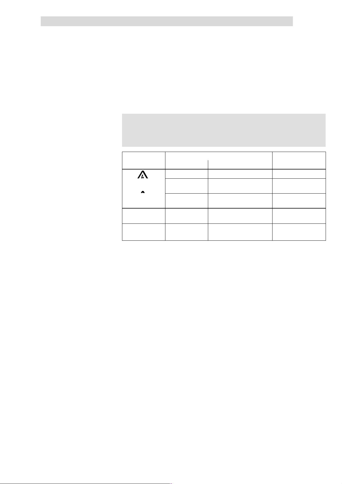
3.4 Layout of safety notes
All safety information given in these Instructions have got the same layout:
}
} Signal word! (indicates the severity of danger)
}}
Pictograph
Dangerous electrical voltage
General danger
(
)
Pictograph (indicates the type of danger)
Note (describes the danger and explains how to avoid it)
Signal word
Signal word Meaning
Danger! Impending danger for persons Death or most severe injuries
Warning! Possible, very dangerous
situation for persons
Caution! Possible, dangerous situation for
persons
Stop! Possible material damag e Damage of the drive system
Note! Useful note or tip
If you observe it, handling of the
drive system will be easier.
Possible consequences if
the safety information are
disregarded
Death or most severe injuries
Injuries
or its surroundings
3.4
L
EDSIBS-1.0-06/ 2003
3.4-1
Page 23

Show/Hide Bookmarks
Page 24

Wiring according to EMC
Show/Hide Bookmarks
4 Wiring according to EMC
)
) Note!
))
This topic has not been described yet.
You will be informed as soon as this chapter will be available.
4
L
EDSIBS-1.0-06/ 2003
4.1
Page 25

Show/Hide Bookmarks
Page 26

Feldbus-Baugruppe 2113 INTERBUS
Show/Hide Bookmarks
7
Contents
7 2113 INTERBUS fieldbus module
7.1 Contents
7.2 General information 7.2-1........................................................
7.3 Technical data 7.3-1............................................................
7.3.1 General data and application conditions 7.3-1................................
7.3.2 Rated data 7.3-2.....................................................
7.3.3 Protocol data 7.3-3...................................................
7.3.4 Communication times 7.3-4.............................................
7.3.5 Dimensions 7.3-6.....................................................
7.4 Installation 7.4-1..............................................................
7.4.1 Components of the fieldbus module 7.4-1...................................
7.4.2 Mechanical installation 7.4-2............................................
7.4.3 Electrical installation 7.4-3.............................................
7.5 Commissioning 7.5-1...........................................................
7.5.1 Before switching on 7.5-1...............................................
7.5.2 Possible settings with the front switch 7.5-2.................................
7.5.3 Possible settings with INTERBUS master 7.5-4................................
7.5.4 Ensure that the settings match the 2111 fieldbus module 7.5-5...................
7.5.5 Commissioning of 2113 fieldbus module 7.5-5...............................
7.5.6 Prepare controller for INTERBUS operation 7.5-6..............................
7.5.7 Controller enable via DRIVECOM 7.5-7.....................................
7.5.8 DRIVECOM compatibility 7.5-8...........................................
7.5.9 Special features when using 82XX, 8200 vector and 93XX 7.5-9..................
7.6 Data transfer 7.6-1.............................................................
7.6.1 Process data channel configuration 7.6-2...................................
7.6.2 Process data signals of Lenze controllers 7.6-7...............................
7.6.3 Process data preconfiguration depending on L-C0009 7.6-24......................
7.6.4 Examples for the configuration of PI/PO data 7.6-26............................
7.6.5 Device control 7.6-28..................................................
7.6.6 DRIVECOM control 7.6-30................................................
7.6.7 DRIVECOM profile parameters 7.6-33.......................................
7.6.8 Configuration of the parameter data channel (PCP communication) 7.6-47............
7.7 Troubleshooting 7.7-1...........................................................
7.7.1 Controller is inhibited 7.7-1.............................................
7.7.2 Check INTERBUS 7.7-3.................................................
7.7.3 Reset error (TRIP) 7.7-4................................................
7.7.4 DRIVECOM error codes 7.7-5............................................
7.8 Appendix 7.8-1...............................................................
7.8.1 Code table 7.8-1......................................................
7.8.2 Parameter values of process data preconfiguration 7.8-4........................
7.9 Index 7.9-1..................................................................
7.1
L
EDSIBS-1.0-06/ 2003
7.1-1
Page 27

Show/Hide Bookmarks
Page 28
Feldbus-Baugruppe 2113 INTERBUS
Show/Hide Bookmarks
7
General information
7.2 General information
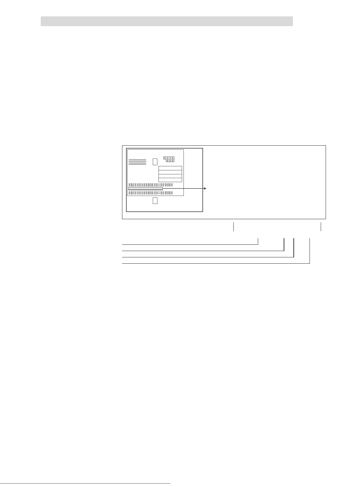
Validity of the Instructions 22
Identification
These Instructions are only valid
l for fieldbus modules as of nameplate data 2113IB.1x.1x.
l together with the documentation for the basic devices permitted for the
application.
L
Type
Id.-No.
Prod.-No.
Ser.-No.
E82AF000P0B201XX
7.2
Type code 33.2113IB 1x 1x
Type series INTERBUS
Hardware version
Software version
Variant
239 9371BC013
L
EDSIBS-1.0-06/ 2003
7.2-1
Page 29

7
Show/Hide Bookmarks
Feldbus-Baugruppe 2113 INTERBUS
7.2
Application range
General information
The fieldbus module can be used together with devices with the following
nameplate data:
820X E./C. 2x. 1x. Vxxx (8201 - 8204)
821X E./C. 2x. 2x. Vxxx (8211 - 8218)
822X E. 1x. 1x. Vxxx (8221 - 8227)
824X E./C. 1x. 1x. Vxxx (8241 - 8246)
82EVxxxxxBxxxXX Vx 13 (8200 vector)
82CVxxxxxBxxxXX Vx 13 (8200 vector, Cold plate)
EPL 10200 I./T. 1x 1x (Drive PLC)
93XX Ex/Cx 2x 1x (9321 - 9332)
93XX E.C. I./T. 2x 1x (Servo PLC 9300)
Type
Design:
Ex = Built-in unit IP20
Cx = Cold plate
I=ServoPLC
xK = Cam profiler
xP = Positioning controller
xR = Register controller
xS = Servo inverter
Features
Hardware version
Software version
Variant
Explanation
The fieldbus modle 2113 INTERBUS is
l an attachable intelligent additional module with a 16-bit micro-processor.
l compatible with the Lenze fieldbus module 2111 INTERBUS.
Benefits of the fieldbus module 2113 INTERBUS:
l Communication of 82XX, 8200 vector, 93XX controllers and 9300 servo PLC
via INTERBUS.
l Communication of Lenze Drive PLCs via INTERBUS.
l Bus connection via remote bus according to standard RS485.
l Access to all Lenze parameters.
l BecauseofitsDIPswitchonthefront:
– Choice between DRIVECOM drive profile 21 or device control AIF-CTRL.
– Change of baud rate.
– Change of number of process data words (PD)
– Change of number of parameter data words (PCD).
7.2-2
EDSIBS-1.0-06/ 2003
L
Page 30
Feldbus-Baugruppe 2113 INTERBUS
Baudrate500kBit/s
Show/Hide Bookmarks
7
Technical data
General data and application conditions
7.3 Technical data
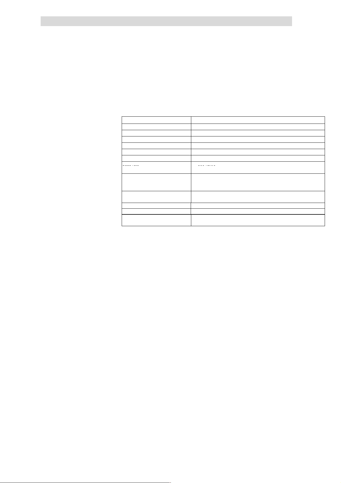
7.3.1 General data and application conditions
Field Values
Order number EMC 2113IB
Communication media RS485
Network topology Ring
INTERBUS participant Slave
Communication profile PCP 2.0
Drive profile DRIVECOM profile 21
Baud rate • 500 kBit/s
Ambient temperature during operation:
Permissible humidity Class 3K3 to EN 50178
Degree of pollution VDE0110, part 2, pollution degree 2
Enclosure IP 20
Voltage supply (internal / external),
^ 7.4-5
see
• 2MBit/s
during transport:
during storage
(without condensation, average relative humidity 85%)
External supply via separate power supply unit
(+24 V DC
0 °C
°C
-25
-25
°C
±10 %, max. 120 mA)
7.3
7.3.1
to
to
to
55 °C
70 °C
60 °C
L
EDSIBS-1.0-06/ 2003
7.3-1
Page 31

7
Show/Hide Bookmarks
Feldbus-Baugruppe 2113 INTERBUS
7.3
7.3.2
7.3.2 Rated data
Technical data
Insulation voltages between incoming bus
and ...
• Reference earth / PE 50 V AC Mains isolation
• External supply (terminal 39/59) 50 V AC Mains isolation
• Power stage
– 820X / 821X 270 V AC Basic insulation
– 822X / 8200 vector 270 V AC Double insulation
– 93XX 270 V AC Double insulation
• Control terminals
– 820X / 8200 vector
(with internal supply)
– 8200 vector
(with external supply)
– 821X 50 V AC Mains isolation
– 822X 270 V AC Basic insulation
– 93XX 270 V AC Basic insulation
• Outgoing bus (OUT) 50 V AC Mains isolation
Rated insulation voltage Type of insulation
0VAC No mains isolation
100 V AC Basic insulation
Rated data
Insulation voltages between outgoing bus and
...
• Earth reference / PE 50 V AC Mains isolation
• External supply (terminal 39/59) 0VAC No mains isolation
• Power stage
– 820X / 821X 270 V AC Basic insulation
– 822X / 8200 vector 270 V AC Double insulation
– 93XX 270 V AC Double insulation
• Control terminals
– 820X / 8200 vector
(with internal supply)
– 8200 vector
(with external supply)
– 821X 50 V AC Mains isolation
– 822X 270 V AC Basic insulation
– 93XX 270 V AC Basic insulation
• Input bus (IN) 50 V AC Mains isolation
Rated insulation voltage Type of insulation
0VAC No mains isolation
100 V AC Basic insulation
7.3-2
EDSIBS-1.0-06/ 2003
L
Page 32

Feldbus-Baugruppe 2113 INTERBUS
(
)
Show/Hide Bookmarks
7
Technical data
Protocol data
7.3.3 Protocol data
7.3.3
Field Values
Maximum number of controllers
Process data words (PD) 1 ... 10 (selectable) Default setting: 2 words
Parameter data words (PCP) 0, 1, 2, 4 Default setting: 1 word
Maximum number of data words As a maximum the data word sum (PD + PCP) is to amount to 10 words.
INTERBUS ID (module ID)
Maximum PDU length 64 byte
Supported PCP services Initiate, abort, status, identify, Get-0V-long, read, write
Dependent on INTERBUS master (e.g. Phoenix Contact G4-Master).
For the following data, always the smaller value applies dependent on the
fact, whether PCP communication is available or not:
• With PCP communication:
• Without PCP communication:
Module ID for set length
3
227
224
225
dec
dec
dec
dec
=03
=E3
=E0
=E1
hex
hex
hex
hex
62 or
256/number PD
PCP 0 words
PCP 1 word
PCP 2 words
PCP 4 words
7.3
L
EDSIBS-1.0-06/ 2003
7.3-3
Page 33

7
Show/Hide Bookmarks
Feldbus-Baugruppe 2113 INTERBUS
7.3
7.3.4
7.3.4 Communication times
7.3.4.1 Cycle time
The cycle time of a communication system is the time needed to exchange all
process data
to the bus.
It depends on the communication system data and is calculated as follows
(example: baud rate of 500 kbit/s):
í
= Eå + QU + P × _hF × PKPR × NM−P+ MKOQ × i + MKO
ÅóÅä
Fig. 7.3-1 is shows the ratio between cycle time and number of connected
controllers.
The indicated values refer to the connection of Lenze controllers (e. g. 2XX) with
48 data bits (1 parameter data word + 2 process data words, see
Technical data
Communication times
(¶ 7.6-7) between the INTERBUS master and the devices connected
t
cycl
n Sum of all data bit in the INTERBUS ring
BT Number of bus terminals
L Length of remote bus cab le in [km]
Cycletimein[ms]
(¶ 7.3-3).
Cycletime[ms]
NO
NM
U
S
Q
O
N
NM
Number of devices connected to the bus
Fig. 7.3-1 INTERBUS cycle time for controllers
OM
PM QM
RM SM
7.3-4
EDSIBS-1.0-06/ 2003
L
Page 34

Feldbus-Baugruppe 2113 INTERBUS
Show/Hide Bookmarks
7
Technical data
Communication times
7.3.4.2 Processing time in the controller
The processing time of the controller is added to the INTERBUS cycle time.
The processing time of the controller depends on the series and version:
Processing t ime 820X
For the 820X series several processing steps are required. These steps are
processed cyclically.
A processing cycle consists of:
l Writing of control word or setpoint, if the value has changed
l Alternating reading of status word and actual value
l Processing of PCP parameter ac cess, if there is a service.
)
) Note!
))
A change of the setpoint signal results in writing the control word.
7.3
7.3.4
Processing t ime 821X /
8200 vector / 822X
If the time tolerances caused by cyclic reading of the status word/ac tual value are
too large, the alternating reading of the status word and the actual value can be
suppressed. This is controlled by bit 15 (PE inhibit) of the DRIVECOM control
(¶ 7.6-36).
word:
A suppression of the processing of parameter access is not necessary, since this
is controlled by the user.
In the following table you will find a list of the processing times:
Processing step Max. processing time
Parameter 70 -8 Setpoint 35 -8 180
Control word 35 -8 180
Actual value 35 -8 180
Status word 35 -8 180
Setpoint + control word 70 -16 180
Setpoint + control word + actual
value + status word
The parameter data (transmission via PCP channel) and process data are
independent of each other.
l Parameter data (PCP): approx. 30 ms + 20 ms tolerance
l Process data (PD): approx. 3 ms + 2 ms tolerance
[ms]
140 -32 180
Processing tolerance
[ms]
Additional parameter
[ms]
Processing t ime 9300 servo
inverter
Processing t ime Drive PLC / 9300
Servo PLC
L
The parameter data (transmission via PCP channel) and process data are
independent of each other.
l Parameter data (PCP): approx. 30 ms + 20 ms tolerance
l Process data (PD): approx. 2 ms + 1 ms tolerance
l Parameter data (PCP): 30 ms + 20 ms tolerance
l Process data (PD): depending on process image
EDSIBS-1.0-06/ 2003
7.3-5
Page 35

7
Show/Hide Bookmarks
Feldbus-Baugruppe 2113 INTERBUS
7.3
7.3.5
7.3.5 Dimensions
Drivecom
Length
Baud
PCP
PD
OPEN
12345678
Bus
Drive
L
2113
a
INTERBUS
24V DC
_
+
b
OUT
IN
a61mm
b75mm
e28mm
e1 18 mm
18
Technical data
Dimensions
e1
e
2113IBU013
7.3-6
EDSIBS-1.0-06/ 2003
L
Page 36

Feldbus-Baugruppe 2113 INTERBUS
0
1
SLOW(1Hz)
dPC
P
S()oypocessdata
–indicatesinadmissiblesettings:
–
Show/Hide Bookmarks
7
Installation
Components of the fieldbus module
7.4 Installation
7.4.1 Components of the fieldbus module
Fig. 7.4-1 Components of the fieldb us module
Pos LED status Explanation 24
0
1
Green bus LED (voltage supply)
ON The fieldbus module is supplied with voltage and is connected to the drive controller.
OFF The fieldbus module is not supplied with voltage. The drive controller or external voltage
supply is switched off.
BLINKING The fieldbus module is supplied with voltage, but it is not connected to the drive
controller, because
• the fieldbus module was not plugged on the drive controller correctly
• the data transfer of/to the drive controller is not possible (e. g. the drive controller is
in the initialisation phase).
Yellow bus LED (communication)
ON Fieldbus module is initialised,
inactive INTERBUS communication of the master
OFF Fieldbus module is not initialised yet
BLINKING Active INTERBUS communication
•
• FAST (4 Hz): only process data
• VERY FAST (8 Hz)
:processdata an
7.4
7.4.1
2113IBU001
communication.
L
2
4
5
6
7
8
)
) Note!
))
Red and green drive LED indicate the operating mode of the drive controller 82XX or 93XX (see the
Operating Instructions of the drive controller)
INTERBUS output (OUT), Sub-D socket connector, 9-pole
INTERBUS input (IN), Sub-D plug connector, 9-pole
PE connection
Fixing screw
Plug connector, connection for external voltage supply ^ 7.4-4
Only for 820X and 821X: If required use an additional PE screen
cable which avoids EMC-related communication interference in
surroundings with interferences.
EDSIBS-1.0-06/ 2003
Datawordsum:PD+PCP>10ornumber of process data words: PD = 0.
The fieldbus module goes on working internally with the following values:
PD=2andPCP=1
^ 7.4-7
^ 7.4-6
see note
7.4-1
Page 37

7
Show/Hide Bookmarks
Feldbus-Baugruppe 2113 INTERBUS
7.4
7.4.2
7.4.2 Mechanical installation
l Plug the fieldbus module onto the basic device (here: 8200 vector).
l Fasten the fieldbus module with the fixing screw onto the basic device to
ensure a good PE connection.
Installation
Mechanical installation
25 2102LEC014
)
) Note!
))
For the internal supply of the fieldbus module through the 8200
vector frequency inverter the interface of the jumper must be
adapted (see illustration above). Please observe the notes
^ 7.4-5.
7.4-2
EDSIBS-1.0-06/ 2003
L
Page 38

Feldbus-Baugruppe 2113 INTERBUS
Show/Hide Bookmarks
7
Installation
Electrical installation
7.4.3 Electrical installation
Wiring to the INTERBUS master
)
) Note!
))
l The bus system must be designed as a ring.
7.4
7.4.3
An additional mains isolation is required, if
l an 820X or 821X is connected to an INTERBUS master and
l a safe mains isolation (double basic insulation) is required
according to VDE 0160.
Use e.g. a bus terminal or an interface module for the INTERBUS
master with an additional mains isolation (see the corresponding
information of the manufacturer).
The incoming bus (IN) is isolated from the supply voltage and the
outgoing bus (OUT).
The supply voltage has the same potential as the outgoing data
bus (OUT).
Wiring example
l Go-and-return lines are both in the same bus cable.
l The ring connects the INTERBUS master with all devices connected to the
bus.
1
3.2
400 m
2
Fig. 7.4-2 Wiring examp le, INTERBUS (baud rate 500 kbit/s)
4.2
3.2
3.1
8200 vector
+
2113
4.1
82XX
+
2112
4.2 4.24.2
20 m
INTERBUS-Loop 200 m
400 m
93XX
2112
3.1
93XX
+
2113
+
3.23.2
3.1
82XX
+
2111
4.14.1
8200 vector
2112
3
+
4
2131IBU003
L
EDSIBS-1.0-06/ 2003
7.4-3
Page 39

7
Show/Hide Bookmarks
Feldbus-Baugruppe 2113 INTERBUS
7.4
7.4.3
Installation
Electrical installation
Pos. Element Explanation
1 INTERBUS master with
interface module
2 INTERBUS loop bus
terminal
3 Remote bus
Fig. 5.4-2 Pos. 3
3.1 Long distance bus module Bus participant in the long distance bus; e.g. Lenze controller with INTERBUS
3.2 Remote bus cable Connects the INTERBUS master interface module with the bus terminal and/or
4 INTERBUS loop,
peripheral bus
Fig. 5.4-2 Pos. 4
4.1 INTERBUS loop module Bus participant in the INTERBUS loop; e.g. Lenze controller with INTERBUS loop
4.2 INTERBUS loop cable Connection within the loop
Features:
Communication medium RS485
Network topology Ring
Maximum number of
controllers
Baud rate / cable length
The bus system is a master-slave system, i.e. an INTERBUS master is connected
to several field devices (slaves).
The bus terminal connects a long distance bus to a peripheral bus.
The following connections are possible with remote buses:
• Connections between INTERBUS master interface module and first bus
terminal or first 2113 fieldbus module.
• Connection between bus terminal and 2113 fieldbus module
• Connection between two 2113 fieldbus modules
module (slave). Networking does not require bus terminals.
the long distance bus modules.
Connection in a peripheral-bus station
A peripheral-bus station consists of:
• a bus terminal (Fig. 5.4-2 pos. 2)
• up to eight peripheral bus modules (Fig. 5.4-2 pos. 3)
module 2112
Dependent on INTERBUS master (e.g. Phoenix Contact G4-Master).
For the following data, always the smaller value applies dependent on the fact, whether
PCP communication is available or not:
• With PCP communication: 62 or
• Without PCP communication: 256/number PD
Baud rate Maximum cable length between
neighbouring participants
500 kBit/s 400 m
2MBit/s 150 m
External DC voltage supply 27
Specification of INTERBUS remote bus cable 26
Cable type Yard goods:
Number of conductors 3 x 2, paired with common shielding
Conductor cross-section >0.2mm
DC cable resistance <96Ω/km
Impedance, characteristic 120 Ω±20 % (f = 64 kHz)
Capacitance per unit length < 60 nF/km (f = 800 Hz)
IBS RBC Meter-T, order No. 28 06 28 6 (Fa. Phoenix Contact)
2
100
Ω±15 Ω (f > 1 MHz)
If necessary, supply the 2113 fieldbus module with a separate supply voltage 24
V DC via the two-pole plug connector ±10 % .
Plug connector Name Explanation
+ Vcc24 External supply 24 V DC ± 10 %, 120 mA
- GND24 Reference potential for external voltage supply
Use a separate power supply unit in each control cabinet.
Controller External voltage supply
820X Always required
821X / 822X / 824X and
93XX
8200 vector See information in “internal DC voltage supply”
Only necessary if the mains which supply the corresponding controllers is to be switched
off but the communication must not be interrupted.
7.4-4
EDSIBS-1.0-06/ 2003
L
Page 40

Feldbus-Baugruppe 2113 INTERBUS
Show/Hide Bookmarks
7
Installation
Electrical installation
Connection terminals 28
Internal DC voltage supply 29
Electrical connection Plug connector with threaded terminal end
Possible connections
Tightening torque 0.5 ... 0.6 Nm (4.4 ... 5.3 lb-in)
Bare end 6mm
)
) Note!
))
Basic devices with extended AIF interface opening (8200 vector
front) can be internally supplied. The part of the drawing
highlighted in grey shows the jumper position.
l In the delivery state of the frequency inverter these are not
internally supplied.
l For internal voltage supply, put the jumper in the position
indicated below.
rigid: 1.5 mm2(AWG 16)
flexible:
without wire crimp cap
2
(AWG 16)
1.5 mm
with wire crimp cap, without plastic sleeve
2
(AWG 16)
1.5 mm
with wire crimp cap, with plastic sleeve
2
(AWG 16)
1.5 mm
7.4
7.4.3
only external voltage supply
Lenze setting
Internal voltage supply
L
EDSIBS-1.0-06/ 2003
7.4-5
Page 41

7
Show/Hide Bookmarks
Feldbus-Baugruppe 2113 INTERBUS
7.4
7.4.3
7.4.3.1 Connection from the INTERBUS
L
en
g
P
th
D
D
P
C
P
O
P
E
N
12345678
OUT
IN
riv
B
2113
e
co
a
ud
m
Bus
Drive
L
INTERBUS
+
_
Installation
Electrical installation
24V
DC
2113IBU010
5
9
IN
1
6
Sub-D pin connector (IN)
Pin Name Input/output Explanation
1 DO1 Input RS485: DO1 not inverted
2 DI1 Output RS485: DI1 not inverted
3 GND Reference potential
4 free
5 Vcc5 5VDC
6 /DO1 Input RS485: DO1 inverted
7 /DI1 Output RS485: DI1 inverted
8 Vcc5 5VDC
9 free
Tab. 7.4-1 Pin assignment of the Sub-D pin connector (IN)
2113IBU012
7.4-6
EDSIBS-1.0-06/ 2003
L
Page 42

Feldbus-Baugruppe 2113 INTERBUS
Show/Hide Bookmarks
7
Installation
Electrical installation
7.4.3.2 Connection to the INTERBUS
Length
PD
Drivecom
PCP
OPEN
12345678
OUT
IN
Baud
2113
Bus
Drive
PC
L
IN
T
E
R
B
24V DC
+
_
7.4
7.4.3
U
S
2113IBU010
5
9
OUT
1
6
2113IBU011
Sub-D socket connector (OUT)
Pin Name Input/output Explanation
1 DO2 Output RS485: DO2 not inverted
2 DI2 Input RS485: DI2 not inverted
3
4
GND Reference potential
5 Vcc5 Output 5VDC
6 /DO2 Output RS485: DO2 inverted
7 /DI2 Input RS485: DI2 inverted
8 Vcc5 5VDC
9 RBST Message input The assignment of the Sub-D socket connector
(OUT) with a Sub-D plug is indicated.
Tab. 7.4-2 Pin assignment of the Sub-D socket c onnector (OUT)
L
EDSIBS-1.0-06/ 2003
7.4-7
Page 43

Feldbus-Baugruppe 2113 INTERBUS
Show/Hide Bookmarks
7
Commissioning
Before switching on
7.5 Commissioning
7.5.1 Before switching on
(
( Stop!
((
)
) Note!
))
7.5
7.5.1
Before switching on the mains voltage, check the wiring for
completeness, earth fault and short circuit.
Do not change the switch-on sequence!
L
EDSIBS-1.0-06/ 2003
7.5-1
Page 44

7
4
2
Show/Hide Bookmarks
Feldbus-Baugruppe 2113 INTERBUS
7.5
7.5.2
7.5.2 Possible settings with the front switch
)
) Note!
))
Switches S1 ... S7
l All in OFF position:
The configurations set for the codes L-1910, L-1911
L-1912
l One or several switches in ON position:
All switch positions are valid!
The following must be set:
– Number of process data words (PD),
– Number of parameter data words (PCP) and
– Device control AIF-CTRL / DRIVECOM control
The Lenze setting of the switches (S1 - S8) is OFF .
Switch off the voltage supply of the fieldbus module and
afterwards on again, in order to activate changed settings.
As a maximum the data word sum (PD + PCP) is to amount to 10
words.
Please note that only the switch combinations listed in the
following tables represent defined
unacceptable, the yellow bus LED at the front of the fieldbus
module will start blinking (8kHz).
get active with switching on.
Commissioning
Possible settings with the front switch
and
states. If the settings are
Setting number of process data
words (PD)30
Length
PD
OPEN
12345678
PD S1 S2 S3 S4 Maximum number of
1 OFF OFF OFF ON
2 OFF OFF ON OFF
3 OFF OFF ON ON
4 OFF ON OFF OFF
5 OFF ON OFF ON
6 OFF ON ON OFF
7 OFF ON ON ON
8 ON OFF OFF OFF
9 ON OFF OFF ON 1
10 ON OFF ON OFF 0
)
) Note!
))
Impermissible settings are indicated by the yellow bus LED
(co m municat io n).
Display of the current switch position S1 ... S4 for number of
process data words (PD) is possible because of code L-C1915.
OFF
ON
parameter data words
(PCP)
(¶ 7.4-1) .
2113IBU005
7.5-2
EDSIBS-1.0-06/ 2003
L
Page 45

Feldbus-Baugruppe 2113 INTERBUS
Show/Hide Bookmarks
7
Commissioning
Possible settings with the front switch
Setting number of parameter
data words (PCP)31
Length
OPEN
12345678
PCP S5 S6 Maximum number of process
0 OFF OFF 10 3
1 OFF ON 9 E3
2 ON OFF 8 E0
4 ON ON 6 E1
)
) Note!
))
PCP
Impermissible settings are indicated by the yellow bus LED
(communication)
Display of the current switch position S5/S6 for number of
parameter data words (PCP) is possible because of code L-1917.
OFF
ON
ID code
data words (PD)
(¶ 7.4-1).
7.5
7.5.2
2113IBU005
hex
hex
hex
hex
Select AIF-CTRL or DRIVECOM
control32
Select baud rate33
Drivecom
OFF
OPEN
1234567 8
S7 Explanation
OFF with AIF-CTRL control
ON with DRIVECOM control
)
) Note!
))
Display of the current switc h position S7 is possible because of
code L-C1916.
Baud
OPEN
12345678
S8 Baud rate Maximum cable length between neighboring participants
OFF 500 kBit/s 400 m
ON 2MBit/s 150 m
ON
OFF
ON
2113IBU005
2113IBU005
L
)
) Note!
))
The baud rate can only be set through switch S8.
EDSIBS-1.0-06/ 2003
7.5-3
Page 46

7
p
L-C1916Displ
h
S
C1917DisplayofcurrentswitchpositionsS5/S6fornumberofparameterdatawords(PCP)
Show/Hide Bookmarks
Feldbus-Baugruppe 2113 INTERBUS
7.5
7.5.3
7.5.3 Possible settings with INTERBUS master
)
) Note!
))
Conditions for setting through the INTERBUS master:
Switch S1 ... S7 = OFF
l The configurations set for the codes L-1910, L- 1911 and
L-1912
l The settings can be changed.
l Switch off the voltage supply of the fieldbus module and
afterwards on again, in order to activate changed settings.
As a maximum the data word sum (PD + PCP) is to amount to 10
words.
Index detection: 24575 - Lenze code number (L-C xxxx )
Impermissible settings are indicated by the yellow bus LED
(communication)
get active with switching on.
(¶ 7.4-1).
Commissioning
Possible settings with INTERBUS master
Display codes
Code Values Explanation
L-C1910 2 ... 20 (1 ... 10 words) Number of process data bytes
L-C1911
L-C1912
Code Explanation
L-C1915 Display of the current switch positions S1 ... S4 for number of process data words
-L-
0: Device control AIF-CTRL
1: DRIVECOM control
Number of parameter
data words (PCP)
0 3
1 E3
2 E0
4 E1
ay ofthe current position ofswitc
ID code
hex
hex
hex
hex
7.
(2 Process data bytes = 1 Process data word)
Operation with device control AIF-CTRL or
operation with DRIVECOM-Profil 21
Number of parameter data words (PCP)
.
7.5-4
EDSIBS-1.0-06/ 2003
L
Page 47

Feldbus-Baugruppe 2113 INTERBUS
Show/Hide Bookmarks
7
Commissioning
Ensure that the settings match the 2111 fieldbus module
7.5.4 Ensure that the settings match the 2111 fieldbus module
Drivecom
Length
Length
PD
12345678
S1 ... S8 Explanation
OFF
(Lenze setting)
OPEN
PCP
Baud
OFF
ON
The response is the same as of the Lenze fieldbus module “2111 INTERBUS”, if the
Lenze setting for the switches (S1 - S7 = OFF) and
L-C1912 = 1 remain unchanged.
7.5.5 Commissioning of 2113 fieldbus module
1. The fieldbus module must be attached to the controller (¶ 7.4-2).
2. The controller and if available the separate voltage supply for the 2113
fieldbus module must be switched on.
7.5
7.5.4
2113IBU005
codes L-C1910 = 4, L-C1911 = 1 and
3. Check fieldbus module signals:
– The green bus LED indicates the operating status according to the
corresponding description
– The yellow bus LED indicates the communication status according to the
description
– Quick blinking (8 Hz) is the reaction of the yellow bus LED to
impermissible settings. Please see chapter 7.7, ”Troubleshooting and fault
elimination”.
4. You can now communicate with the drive.
– With a PCP communication it is only possible to acc ess the parameters of
the controller after having executed the PCP service ”Initiate“
5. It is then possible to access the parameters via the PCP services ” Read“
and ” Writ e“
(¶ 7.4-1) Pos. 1.
(¶ 7.6-50).
(¶ 7.4-1) Pos. 0.
(¶ 7.6-50).
L
EDSIBS-1.0-06/ 2003
7.5-5
Page 48

7
Show/Hide Bookmarks
Feldbus-Baugruppe 2113 INTERBUS
7.5
7.5.6
Prepare controller for INTERBUS operation
7.5.6 Prepare controller for INTERBUS operation
82XX / 8200 vect or
Preparation Notes
1. L-C0001 (operating mode):
Change value from “0” to “3”
.
2. Terminal 28 (controller
enable) must be HIGH during
INTERBUS operation.
Terminal 28 is always
active!
The controller is now ready to accept process and parameter data from the INTERBUS.
For this use
• the 8201BB for 82XX and
• the keypad for 8200 vector
Alternative
Direct access to the code via INTERBUS.
Example
Set code L-C0001 to “3” (PCP write):
à For conversion formula and parameter value range see ^ 7.6-47
8200 vector (up to SW version 1.1)
à C0410/y (y = 1...16) must be assigned to the AIF control word (AIF-CTRL)
Otherwise, the controller cannot be enabled by the INTERBUS (DRIVECOM
controller status ”OPERATION ENABLED”, see Operating Instructions for the
controller).
821X, 8200vector un d 822X
With these controllers the QSP function is always active. If QSP is assigned to an
input terminal (default setting: not assigned), this terminal must be at HIGH level
during INTERBUS operation (see the corresponding Operating Instructions).
:
– Index: 5FFE
– Subindex: 0
– Value: 30000
i.e. C0410/1 = 10, C0410/2 = 11 .... C0410/16 = 25 (see Operating
Instructions for 8200 vector).
hex
dec
(= 5FFF
− (L-C0001)
hex
hex
Commissioning
)
93XX controllers
Preparation Notes
1. L-C0005: Set “xxx3”. Use the 9371BB keypad
Alternative:
Direct access to the code via INTERBUS.
For the first commissioning you should select the signal configuration 1013 (speed
control).
Example
Set code L-C0005 to “1013” (PCP write):
– Index: 5FFA
– Subindex: 0
– Value: 10130000
à For conversion formula and parameter value range see ^ 7.6-47
2. L-C0142 (autostart lock):
Set “0”.
3. Terminal 28 (controller
enable) must be HIGH during
INTERBUS operation.
Terminal 28 is always
active!
The controller is now ready to accept process and parameter data from the INTERBUS.
Only necessary with DRIVECOM control
Otherwise, the controller cannot be enabled by the INTERBUS (DRIVECOM
controller status ”OPERATION ENABLED”, see Operating Instructions for 93XX).
à With the signal configuration L-C0005=1013, the function QSP (quick stop) and
the CW/CCW changeover are assigned to the digital input terminals E1 and E2
and thus they are always active. For INTERBUS operation E1 must be set to
HIGH level (see Operating Instructions 93XX).
à With the signal configuration L-C0005=xx13, terminal A1 is switched as
voltage output. Thus, only the following terminals can be connected via cables:
– X5.A1 with X5.28 (ctrl. enable)
– X5.A1 with X5.E1 (CW/QSP)
hex
(5FFF
dec
− (L-C0005)
hex
hex
)
7.5-6
EDSIBS-1.0-06/ 2003
L
Page 49

Feldbus-Baugruppe 2113 INTERBUS
Show/Hide Bookmarks
7
Commissioning
Controller enable via D RIVECOM
7.5.7 Controller enable via DRIVECOM
Controllers can be c ontrolled with DRIVECOM process data. The INTERBUS
master has direct access to the process data. In the INTERBUS master, data are
stored in the I/O area.
l Controller enable: DRIVECOM process data word ” Control word”
l Display of actual controller status: DRIVECOM process data word ” Status
word”.
The controller can be enabled by changing to OPERATION ENABLED by means
of the DRIVECOM control word.
Afterwards, the controller can be controlled as usual, e.g. via terminals.
)
) Note!
))
If DRIVECOM control is active and the fieldbus module
l in the controller
– 82XX / 8200 vector “controller inhibit” will be activated if
L-C0001 = 3.
– 93XX “Controller inhibit” will always be active.
l the fieldbus module sets SWITCH ON INHIBIT.
7.5
7.5.7
Enable the controller as follows:
1. Select speed setpoint (2nd process data word; PD2), value
2. Change to ” READY FOR SWITCH ON“
PD output word1 = 0000 0000 0111 1110
3. Wait for the status ” READY FOR SWITCH ON“.
PD input word1 = xxxx xxxx x01x 0001
4. Change to ” OPERTION ENABLED“
PD output word1 = 0000 0000 0111 1111
5. Wait for ” OPERATION ENABLED“ .
PD input word1 = xxx xxx x01x 0111
bin.
bin.
bin
bin
(007E
(007F
hex
hex
).
).
≠ 0.
L
EDSIBS-1.0-06/ 2003
7.5-7
Page 50

7
Show/Hide Bookmarks
Feldbus-Baugruppe 2113 INTERBUS
7.5
7.5.8
7.5.8 DRIVECOM compatibility
The DRIVECOM profile 21 is a specification of important parameters and unit
performance of several manufacturers. The DRIVECOM profile 21 mainly
describes the unit control and a speed operating mode. In addition to the
DRIVECOM specifications there are further Lenze-specific functions, e.g.
digital-frequency connection or DC injection-brake. Thesemanufacturer-specific
specifications require minor changes in the settings to comply with the desired
DRIVECOM compatibility. In the following, you will find the changes required for
the Lenze controllers.
820X With 820X controllers, parameters can only be set when the controller is inhibited.
821X,
8200 vector
and 822X
93XX Set the controller parameters for INTERBUS control, e.g. L-C0005=1013
9300 Servo
PLC
Drive PLC It is necessary to use the device control for the DRIVE PLC.
Commissioning
DRIVECOM compatibility
The controller is inhibited in DRIVECOM status.
• ”SWITCH-ON INHIBIT”
• ”READY FOR SWITCH ON”
• ”SWITCHED ON”
• ”TRIP”
The automatic DC-injection brake must be deactivated in all parameter sets, i. e.
• L-C0106=0
• L-C2106=0
• L-C4106=0 (only 8200 vector)
• L-C6106=0 (only 8200 vector)
If the automatic DC-injection brake is not deactivated (holding time of the DC-injection brake L-C0106
not 0), the controller automatically switches from the status ”OPERATION ENABLED” to the status
”SWITCHED ON” when the speed is 0 and the holding time of the DC-injection brake is elapsed. If the
setpoint is higher than 0, the controller is automatically reset to the status ”OPERATION ENABLED”.
This configuration corresponds to the signal configuration 1000 with the following changes:
• Setpoint selection with INTERBUS
• Unit control with INTERBUS
• Output X5.A1 is selected as voltage output for the internal supply of the digital inputs.
• Actual values and status signals for INTERBUS
For the detailed description of the signal configuration, see 93XX Manual.
The following links must be made in the PLC program.
• AIF1_wDctrlCtrl W DCTRL_wAIF1Ctrl
• DCTRL_wStat W AIF1_wDctrlStat
7.5-8
EDSIBS-1.0-06/ 2003
L
Page 51

Feldbus-Baugruppe 2113 INTERBUS
Show/Hide Bookmarks
7
Commissioning
Special features when using 82XX, 8200 vector and 93XX
7.5.9 Special features when using 82XX, 8200 vector and 93XX
}
} Danger!
}}
Please note
l For safe operation it is absolutely necessary to observe the
notes for the controllers given in this chapter.
l Please observe the corresponding Operating Instructions of the
controllers.
820X • Parameter setting (codes except process data) is only possible when the controller is inhibited
8200 vector • Digital and analog input and output signals can be freely configured (see Operating Instructions for
93XX • Set the signal configuration L-C0005 = xxx3 instead of the operating mode L-C0001.
(DRIVECOM controller status unequal ”OPERATION ENABLED“). Parameters are accepted when the
controller is enabled, but they are not saved.
• A TRIP must only be reset through INTERBUS:
If the controller is set to the status TRIP while being operated with INTERBUS control
(L-C0001 = 3) and if the TRIP is reset through terminal 28, t he drive can start for a short time.
When resetting a fault via INTERBUS, this does not occur.
• After the command ”TRIP reset“ the 820X controller is basically initialized. During this time the
controller does not accept any services.
• Always send the direction of rotation with a low setpoint before the new setpoint:
If the setpoint and the direction of rotation are changed at the same time via the DRIVECOM speed
setpoint, the speed can change to the wrong direction or rotation for a short time. This is because
the setpoint is sent to the controller as unipolar value before and the information about the
direction of rotation is sent.
8200 vector; codes L-C0410, L-C0412, L-C0417 and L-C0421)
• A change of code L-C0001 to “3“ preconfigures the process data words in the controller.
• The change of the code L-C0005 t o xxx3 starts the preconfiguration of the process data words in
the controller
• Set the parameter L-C0142 = 0 (auto start lock), to avoid a short time start of the drive during the
initialization phase.
7.5
7.5.9
L
EDSIBS-1.0-06/ 2003
7.5-9
Page 52

Feldbus-Baugruppe 2113 INTERBUS
Show/Hide Bookmarks
7
Data transfer
7.6 Data transfer
7.6
INTERBUS master and slave communicate by sending data telegrams via the
INTERBUS.
The user data of the data telegram contains parameter data
Different communication channels are assigned to parameter and process data:
Telegram type Communication channel
Process data,
• Setpoints
• Actual values
Parameter data
• Operating parameters
• diagnostics information
• motor data
Tab. 7.6-1 Division of p arameter data and proc ess data into different communic ation channels
The following describes the communication protocol only as much as needed for
networking Lenze controllers.
Process-data channel • Exchange between INTERBUS master and
Parameter data channel
or “PCP channel”
(PCP = Peripherials
Communication Protocol)
controller required as fast as possible. Small
amounts of data for cyclic data transfer.
• The INTERBUS master has direct access to the
process data.
• Process data can control the controller.
• Process data are
– not stored in the controller.
– exchanged between INTERBUS master and
controllers to ensure a constant update of
input and output data.
• In general, the parameter transfer is not as
time-critical as the tranfer of process data.
• Enables access to all Lenze codes and indexes.
or process data.
L
EDSIBS-1.0-06/ 2003
7.6-1
Page 53

7
Show/Hide Bookmarks
Feldbus-Baugruppe 2113 INTERBUS
7.6
7.6.1
7.6.1 Process data channel configuration
7.6.1.1 Process data transfer
Process data telegrams between INTERBUS master and the controllers
connected to the INTERBUS are divided into:
l Process data telegrams from drive (PI)
l Process data telegrams to drive (PO)
)
) Note!
))
As agreed, the data flow is described from the INTERBUS
master’sview:
l PI data of the INTERBUS master are output data for the
controller.
l PO data of the INTERBUS master are input data for the
controller.
Data transfer
Process data channel configuration
Process data telegram from
drive
Process data telegram to
drive
For the cyclic process data telegram from
is called AIF-OUT. The status word included in the process data telegram (byte
1 and byte 2) is sent to the INTERBUS master via this function block.
For the cyclic process data telegram to
is called AIF-IN. The control word included in the process data telegram (byte 1
and byte 2) is sent to the INTERBUS master via this function block.
the drive, the function block to be used
the drive, the function block to be used
7.6-2
EDSIBS-1.0-06/ 2003
L
Page 54

Feldbus-Baugruppe 2113 INTERBUS
Show/Hide Bookmarks
7
Data transfer
Process data channel configuration
7.6.1.2 Setpoint source selection
82XX controllers
Controller 8200 vector
The setpoint source selection for these controllers is determined under code
L-C0001 (5FFE
is set to ”3” whenthecontroller is operated togetherwiththefieldbusmodule.The
process data channel which describes the frequency setpoint (L-C0046) and the
control word (parameter channel, L-C0135) is the setpoint source
)
) Note!
))
The setpoint source selection for these controllers is determined under code
L-C0001 (5FFE
is set to ”3” whenthecontroller is operated togetherwiththefieldbusmodule.The
process data channel which describes the frequency setpoint (L-C0046) and the
control word (parameter channel, L-C0135) is the setpoint source
7.6.1
).An evaluation of process data isonly possible if c ode L-C0001
hex
.
Please ensure that the setpoint source (L-C0001) is the same for
all parameter sets used.
).An evaluation of process data isonly possible if c ode L-C0001
hex
.
7.6
93XX controllers
Servo PLC 9300 / Drive PLC
Check in L-C0412/x whether the assignment of setpoint source and analog signal
is correct and change, if necessary.
)
) Note!
))
Please ensure that the setpoint source selection (L-C0001) is the
same for all parameter sets used.
The value in code C0005 must be set to ”xxx3” for bus operation (x = selected
preconfiguration).
Communication requires that AIF-IN 1 ... 3 or AIF-OUT 1 ... 3 and if available
AIF management are part of the control configuration of the IEC61131 project.
the
L
EDSIBS-1.0-06/ 2003
7.6-3
Page 55

7
Show/Hide Bookmarks
Feldbus-Baugruppe 2113 INTERBUS
7.6
7.6.1
7.6.1.3 Process data configuration
Some data important for the process must be transmitted as quickly as possible.
These data are called process data and stored in the I/O area of the controller for
access from the INTERBUS master.
The process data are cyclic ally exchanged between the controller and the
INTERBUS master.
Theprocess data of a Process-data configurationhave a certain ”Process data
structure“.
The process-data structure is subdivided into
l Process input data (PI data, index = 6000
l Process output data (PO data, index = 6001
The controller receives control information from the INTERBUS master and sends
status information to the master.
The Lenze setting for the process-data length is 4 byte.
The PD length settings are made by means of
Data transfer
Process data channel configuration
, (¶ 7.6-5))
hex
, (¶ 7.6-6))
hex
– DIP switch
– Code L-C1910
The contents of code L-C1910 is overwritten when the DIP switch is used
because the DIP switch settings have higher priority.
)
) Note!
))
(¶ 7.5-2) or
(¶ 7.5-4).
The assignment of the AIF-CTRL control word to PO data is only
useful, if the Drivecom status machine is switched off. This is
achieved by entering 0 under L-C1911 or
the front.
Different controller signals can be assigned to the PI and PO data
words (see
(¶ 7.6-7)).
using the switch S7 at
7.6-4
EDSIBS-1.0-06/ 2003
L
Page 56

Feldbus-Baugruppe 2113 INTERBUS
Show/Hide Bookmarks
7
Data transfer
Process data channel configuration
PI data description (6000
hex
)34
The parameter describes the process data which are sent from the controller to
the INTERBUS master (input data for the INTERBUS master). Paramters of the
described process data assignment of Lenze controllers can be assigned to the
sub-index values (see
changed.
Ensure that the parameters of the process data channel are only used once, i.e.
double assigment must be avoided (example: DC speed and speed setpoint are
sent via AIF-W1).
Parameter name (Index) Subindex Data structure Data type
PI data description (6000
)
) Note!
))
(¶ 7.6-7)). Exception: The value for subindex 1 cannot be
) 1 ... 41 R PBS(20
hex
hex
)
Only the valid subindex is displayed with the parameter 6000
It is determined by PD!
7.6.1
hex
7.6
.
Subindex Meaning Value Lenze setting
1 Number of process data [byte] PD S 2
2 Index PI data word 1 6041
3 Subindex PI data word 1 00
4/5 No entry 00
6 Index PI data word 2 6044
7 Subindex PI data word 2 00
8/9 No entry 00
10 Index PI data word 3 5CA5
11 Subindex PI data word 3 02
12/13 No entry 00
14 Index PI data word 4 5CA5
15 Subindex PI data word 4 03
16/17 No entry
18 Index PI data word 5 5CA5
19 Subindex PI data word 5 04
20/21 No entry
22 Index PI data word 6 5CA5
23 Subindex PI data word 6 05
24/25 No entry
26 Index PI data word 7 5CA5
27 Subindex PI data word 7 06
28/29 No entry
30 Index PI data word 8 5CA5
31 Subindex PI data word 8 07
32/33 No entry
34 Index PI data word 9 5CA5
35 Subindex PI data word 9 08
36/37 No entry
38 Index PI data word 10 5CA5
39 Subindex PI data word 10 09
40/41 No entry
hex
hex
hex
hex
hex
hex
hex
hex
hex
hex
hex
hex
hex
hex
hex
hex
hex
hex
DRIVECOM status word
DRIVECOM speed
AIF-OUT.W2
AIF-OUT.W3
AIF-OUT.W4
AIF-OUT.W5
AIF-OUT.W6
AIF-OUT.W7
AIF-OUT.W8
AIF-OUT.W9
L
EDSIBS-1.0-06/ 2003
7.6-5
Page 57

7
Show/Hide Bookmarks
Feldbus-Baugruppe 2113 INTERBUS
7.6
7.6.1
PO data description (6001
hex
)35
Data transfer
Process data channel configuration
The parameter describes the process data which are sent to the controller from
theINTERBUSmaster(output data for the INTERBUS master). Parameters of the
described proc ess data of Lenze controllers can be assigned to subindex values
(¶ 7.6-7)). Exception: The value for subindex 1 cannot be changed.
(see
Ensure that the parameters of the process data channel are only used once, i.e.
double assigment must be avoided (example: DC speed and speed setpoint are
sent via AIF-W1).
Parameter name (Index) Subindex Data s tructure Data type
PO data description (6001
Subindex Meaning Value Lenze setting Index 6002/
1 Number of process data [byte] PD S 2
2 Index PO data word 1 6040
3 Subindex PO data word 1 00
4/5 No entry 00 1
6 Index PO data word 2 6042
7 Subindex PO data word 2 00
8/9 No entry 00 3
10 Index PO data word 3 5CA7
11 Subindex PO data word 3 02
12/13 No entry 00 5
14 Index PO data word 4 5CA7
15 Subindex PO data word 4 03
16/17 No entry 7
18 Index PO data word 5 5CA7
19 Subindex PO data word 5 04
20/21 No entry 9
22 Index PO data word 6 5CA7
23 Subindex PO data word 6 05
24/25 No entry 11
26 Index PO data word 7 5CA7
27 Subindex PO data word 7 06
28/29 No entry 13
30 Index PO data word 8 5CA7
31 Subindex PO data word 8 07
32/33 No entry 15
34 Index PO data word 9 5CA7
35 Subindex PO data word 9 08
36/37 No entry 17
38 Index PO data word 10 5CA7
39 Subindex PO data word 10 09
40/41 No entry 19
) 1 ... 41 R PBS(20
hex
DRIVECOM control word 0
hex
DRIVECOM speed setpoint 2
hex
AIF-IN.W2 4
hex
hex
AIF-IN.W3 6
hex
hex
AIF-IN.W4 8
hex
hex
AIF-IN.W5 10
hex
hex
AIF-IN.W6 12
hex
hex
AIF-IN.W7 14
hex
hex
AIF-IN.W8 16
hex
hex
AIF-IN.W9 18
hex
hex
hex
)
Bit
7.6-6
EDSIBS-1.0-06/ 2003
L
Page 58

Feldbus-Baugruppe 2113 INTERBUS
Show/Hide Bookmarks
7
Data transfer
Process data signals of Lenze controllers
7.6.2 Process data signals of Lenze controllers
7.6.2.1 Process data signals for frequency inverters 82XX
Process data telegram from
drive
ThefollowingparameterscanbeassignedtothePI-data:
Index Subindex Name Explanation Lenze setting:
6041 0 DRIVECOM status word PI data word 1 ^ 7.6-39
6044 0 DRIVECOM speed Actual speed [rpm] PI data word 2 ^ 7.6-42
6054 0 DRIVECOM actual
percentage value
5F69 0 Device status word
(L-C0150)
5CA5 1 AIF-OUT.W1 AIF word 1
Actual speed [%]
100% = 16383
Index 6000
7.6
7.6.2
see
hex
^ 7.6-43
Table below
L
EDSIBS-1.0-06/ 2003
7.6-7
Page 59

7
Show/Hide Bookmarks
Feldbus-Baugruppe 2113 INTERBUS
7.6
7.6.2
Device status word AIF-STAT for 82XX (Lenze code C0150, index 5F69
Bit 820X 821x, 822x
0 Actual parameter set 0=Parameterset1or3active
1=Parameterset2or4active
1 IMP (pulse inhibit) 0 = Pulses for power stage enabled
1 = Pulses for power stage inhibited
2 I
(current limit reached) 0 = Current limit not reached
max
1 = Current limit reached
3 not assigned fd=f
4 fd=f
5 Qmin (f
dset
≤ f
) 0 = Qmin not active
d
dQmin
6 fd+ 0 (act. frequency = 0) 0=f
0=f
≠ f
d
dset
1=fd=f
dset
1=Qminactive
≠ 0
d
+0
1=f
d
7 Ctrl. inhibit (controller inhibit) 0 = Controller not inhibited
1 = Controller inhibited
8...11 Controller status 0 = Unit initialisation
8=Erroractive
12 Overtemperature warning 0=Nowarning
1=Warning
13 V
(DC-bus overvoltage) 0 = No overvoltage
Gmax
1 = Overvoltage
14 Direction of rotation 0 = CW rotation
1 = CCW rotation
15 Ready for operation 0 = Not ready for operation
1 = Ready for operation
hex
Process data signals of Lenze controllers
)
Actual parameter set 0=Parameterset1or3active
IMP (pulse inhibit) 0 = Pulses for power stage enabled
I
(current limit reached) 0 = Current limit not reached
max
dset
RFG on = RFG off 0=RFGon≠ RFG off
Qmin (f
d
fd+ 0 (act. frequency = 0) 0=f
Ctrl. inhibit (controller inhibit) 0 = Controller not inhibited
Controller status 0 = Controller initialization
Overtemperature warning 0=Nowarning
V
(DC-bus overvoltage) 0 = No overvoltage
Gmax
Direction of rotation 0 = CW rotation
Ready for operation 0 = Not ready for operation
1=Parameterset2or4active
1 = Pulses for power stage inhibited
1 = Current limit reached
0=f
1=fd=f
1 = RFG on = RFG out
≤ f
) 0 = Qmin not active
dQmin
1=Qminactive
1=f
1 = Controller inhibited
2 = Switch on inhibit
3 = Operation inhibited
4 = Flying-restart circuit active
5 = DC brake active
6 = Operation enabled
7 = Message active
8 = Error active
1=Warning
1 = Overvoltage
1 = CCW rotation
1 = Ready for operation
Data transfer
≠ f
d
dset
dset
≠ 0
d
+0
d
- / fd=fdset
fd=fdset / RFG
ctrl. inhibit
B11 B10 B9 B8
0
0
0
1
0
0
1
0
0
.
.
.
.
.
.
.
.
.
.
.
.
.
.
.
.
.
.
PAR
IMP
Imax
Qmin
fd>0
STAT
0
0
2
0
3
1
.
.
.
.
.
.
Vgmax
RDY
C0050
.
.
.
.
.
.
T
R/L
.B0
.B1
.B2
.B3
.B4
.B5
.B6
.B7
.B8
16 bits
.B9
.B10
.B11
ü
.B12
.B13
.B14
.B15
AIF
16 bits
2141LON012_en
Fig. 7.6-1 Read access to status word and actual frequency in 82XX (fixed assignment)
7.6-8
EDSIBS-1.0-06/ 2003
L
Page 60

Feldbus-Baugruppe 2113 INTERBUS
Show/Hide Bookmarks
7
Data transfer
Process data signals of Lenze controllers
Process data telegram to drive
ThefollowingparameterscanbeassignedtothePO-data:
Index Subindex Name Explanation Lenze setting:
6040 0 DRIVECOM control word PO data word 1 ^ 7.6-36
6042 0 DRIVECOM speed
6052 0 DRIVECOM percentage
5F78 0 Device control word
1 AIF-IN.W1 AIF word 1. See the
5CA7
)
) Note!
))
7.6.2
Index 6001
setpoint
setpoint
(L-C0135)
The assignment of the AIF-CTRL control word to PO data is only
useful, if the Drivecom status machine is switched off. This is
achieved by entering 0 under L-C1911 or
the front.
Speed setpoint [rpm] PO data word 2 ^ 7.6-42
Speed setpoint [%]
100% = 16383
following description.
hex
using the switch S7 at
see
^ 7.6-43
Table below
7.6
L
EDSIBS-1.0-06/ 2003
7.6-9
Page 61

7
0
0,0
1
01JOG1activeinC0037
R
d
Show/Hide Bookmarks
Feldbus-Baugruppe 2113 INTERBUS
7.6
7.6.2
Control w ord AIF- CTRL for 82XX (Lenze code C0135, index 5F78
Bit 820X 821x, 822x
00 = C0046 active
01 = JOG1 active in C0037
10 = JOG2 active in C0038
11 = JOG3 active in C0039
02 CW/CCW (CW rotation/
03 QSP (quick stop) 0 = QSP not active
04 RFG stop (stop of the ramp function generator) 0 = RFG stop not active
05 RFG zero (deceleration along the Tiframp C0013) 0 = RFG zero not active
06
07 DOWN function for motor potentiometer 0 = DOWN not active
08 Reserved
09 Ctrl. inhibit (controller inhibit) 0 = Controller not inhibited
10
11
12 PAR1 (Parameter set changeover) 0 -> 1 = Parameter set
13 Reserved Reserved
14 DC brake (DC injection brake) 0 = DC brake not active
15 Reserved Reserved
CCW rotation)
Reserved
eserve
0 = CW rotation
1 = CCW rotation
1=QSPactive
1 = Controller inhibited
1 -> 0 = Parameter set
1 = DC brake active
)
hex
00 = C0046 active
01 = JOG1 active in C0037
10 = JOG2 active in C0038
11 = JOG3 active in C0039
CW/CCW (CW rotation/CCW rotation) 0 = CW rotation
QSP (quick stop) 0 = QSP not active
UP function for motor potentiometer 0=UPnotactive
Ctrl. inhibit (controller inhibit) 0 = Controller not inhibited
Reserved
TRIP reset 0 -> 1 = Edge from 0 to 1
PAR1 (Parameter set changeover) 0 -> 1 = Parameter set
DC brake (DC injection brake) 0 = DC brake not active
Process data signals of Lenze controllers
Data transfer
1 = CCW rotation
1=QSPactive
1=RFGstopactive
1=RFGzeroactive
1=UPactive
1 = DOWN active
1 = Controller inhibited
1 -> 0 = Parameter set
1 = DC brake active
AIF
16 bits
16 bits
.B0
.B1
.B2
.B3
.B4
.B8
.B9
.B10
.B11
.B12
.B13
.B14
.B15
0
011
JOG/
C046
0101
QSP
...
...
...
CINH
TRIP-SET
TRIP-RESET
C0046
Fig. 7.6-2 Access to control word and ac tual frequency in 82XX (fixed assignment)
CW/
CCW
PAR
DC
brake
2141LON010_en
7.6-10
EDSIBS-1.0-06/ 2003
L
Page 62

Feldbus-Baugruppe 2113 INTERBUS
C
A
Show/Hide Bookmarks
7
Data transfer
Process data signals of Lenze controllers
7.6.2.2 Process data signals for 8200 vector frequency inverters
The function block AIF (AIF=automation interface) is the data interface between
the 8200 vector and the fieldbus module. The function block consists of AIF-OUT
and AIF-IN.
Process data telegram from
drive
ThefollowingparameterscanbeassignedtothePI-data:
Index Subindex Name Explanation Lenze setting:
6041 0 DRIVECOM status word PI data word 1 ^ 7.6-39
6044 0 DRIVECOM speed Actual speed [rpm] PI data word 2 ^ 7.6-42
6054 0 DRIVECOM actual
5F69 0 Device status word
1 AIF-OUT.W1 AIF word 1
5
5
2 AIF-OUT.W2 AIF word 2 PI data word 3
AIF-OUT.Wx is parameterised under code L-C0421.
percentage value
(L-C0150)
Actual speed [%]
100% = 16383
Index 6000
7.6
7.6.2
see
hex
^ 7.6-43
Table below
L
EDSIBS-1.0-06/ 2003
7.6-11
Page 63

7
Show/Hide Bookmarks
Feldbus-Baugruppe 2113 INTERBUS
7.6
7.6.2
Controller status word AIF-STAT for 8200 vector (Lenze code C0150, index 5F69
AIF-STAT.Bxx Lenze setting Adjustable in code L -0417/..
0 DCTRL-PAR-B0 1
1 DCTRL1-IMP 2
2 MCTRL1-IMAX 3
3 MCTRL1-RFG1=NOUT 4
4 NSET1-RFG1-I=0 5
5 PCTRL1-QMIN 6
6 DCTRL1-NOUT=0 7
7 DCTRL1-CINH 8
8...11 Controller status
0 = Controller initialization
2 = Switch on inhibit
3 = Operation inhibited
4 = Flying-restart circuit active
5 = DC brake active
6 = Operation enabled
7 = Message active
8 = Error active
12 DCTRL1-OH-WARN 13
13 DCTRL1-OV 14
14 DCTRL1-CCW 15
15 DCTRL1-RDY 16
Process data signals of Lenze controllers
)
hex
Reserved
Data transfer
C0417/1
DCTRL1-IMP
C0417/3
C0417/4
C0417/5
C0417/6
DCTRL1-NOUT=0
DCTRL1-CINH
DCTRL1-STAT*1
DCTRL1-STAT*2
DCTRL1-STAT*4
DCTRL1-STAT*8
DCTRL1-OH-WARN
DCTRL1-OV
C0417/15
C0417/16
C0421/1
C0421/2
STAT1
AIF-OUT.W1
AIF-OUT.W2
.B0
.B1
.B2
.B3
.B4
.B5
.B6
.B7
.B8
.B9
.B10
.B11
.B12
.B13
.B14
.B15
AIF-OUT
.B0
.B1
.B2
.B3
.B4
.B5
.B6
.B7
.B8
AIF-STAT
.B9
16 bits
.B10
.B11
.B12
.B13
.B14
.B15
16 bits
16 bits
Fig. 7.6-3 Function block AIF-OUT in 8200 vector (freely p rogrammable assignment)
AIF
2141LON013_en
7.6-12
EDSIBS-1.0-06/ 2003
L
Page 64

Feldbus-Baugruppe 2113 INTERBUS
C
A
Show/Hide Bookmarks
7
Data transfer
Process data signals of Lenze controllers
Process data telegram to drive
ThefollowingparameterscanbeassignedtothePO-data:
Index Subindex Name Explanation Lenze setting:
6040 0 DRIVECOM control word PO data word 1 ^ 7.6-36
6042 0 DRIVECOM speed
6052 0 DRIVECOM percentage
5F78 0 Device control word
1 AIF-IN.W1 AIF word 1
5
7
2 AIF-IN.W2 AIF word 2
AIF-IN.Wx is parameterised under code L-C0412.
setpoint
setpoint
(L-C0135)
Index 60001
Speed setpoint [rpm] PO data word 2 ^ 7.6-42
Speed setpoint [%]
100% = 16383
Frequency and speed
are normalised with
24000 ≡ 480 Hz.
PO data word 3
Frequency and speed
are normalised with
24000 ≡ 480 Hz.
hex
see
^ 7.6-43
Table below
7.6
7.6.2
)
) Note!
))
The assignment of the AIF-CTRL control word to PO data is only
useful, if the Drivecom status machine is switched off. This is
achieved by entering 0 under L-C1911 or
the front.
using the switch S7 at
L
EDSIBS-1.0-06/ 2003
7.6-13
Page 65

7
00,
01NSET1JOG1(C0037)activ
e
1
Show/Hide Bookmarks
Feldbus-Baugruppe 2113 INTERBUS
7.6
7.6.2
Control w ord AIF- CTRL for 8200 vector (Lenze code C0135, index 5F78
AIF-CTRL.Bxx Default setting:
00,
01
02 DCTRL1-CW/CCW 0=notactive
03 AIF-CTRL-QSP 0=notactive
04 NSET1-RFG1-STOP 0=notactive
05 NSET1-RFG1-0 0=notactive
06 MPOT1-UP 0=notactive
07 MPOT1-DOWN 0=notactive
08 Freely configurable by user 9
09 AIF-CTRL-CINH 0=notactive
10 AIF-CTRL-TRIP-SET 0=notactive
11 AIF-CTRL-TRIP-RESET 0 -> 1 = Edge from 0 to 1 AIF-CTRL-TRIP-RESET 0 -> 1 = Edge from 0 to 1 12
12 DCTRL1-PAR2/4 0=notactive
13 DCTRL1-PAR3/4 0=notactive
14 MCTRL1-DCB 0=notactive
15 Freely configurable by user Freely configurable by user 16
00 = C0046 active
01 = NSET1-JOG1 (C0037) active
10 = NSET1-JOG2 (C0038) active
11 = NSET1-JOG3 (C0039) active
C0001=3 if C0007
≤ 51
1=active
1=active
1=active
1=active
1=active
1=active
1=active
1=active
1=active
1=active
1=active
Freely configurable by user
AIF-CTRL-QSP 0=notactive
Freely configurable by user
AIF-CTRL-CINH 0=notactive
AIF-CTRL-TRIP-SET 0=notactive
Freely configurable by user
Process data signals of Lenze controllers
)
hex
Default setting:
C0001=3 if C0007 > 51
1=active
1=active
1=active
Data transfer
Adjustable in L-C0410/..
1
2
3
4
5
6
7
8
10
11
13
14
15
AIF
AIF-CTRL
16 bits
16 bits
16 bits
.B0
.B1
.B2
.B3
.B4
.B8
.B9
.B10
.B11
.B12
.B15
AIF-IN
DCTRL
QSP
...
...
...
...
...
...
Fig. 7.6-4 Function block AIF-IN in 8200 vector (freely programmable assignment)
...
...
...
DCTRL
CINH
TRIP-SET
TRIP-RESET
...
...
...
AIF-IN.W1
AIF-IN.W2
2141LON011_en
7.6-14
EDSIBS-1.0-06/ 2003
L
Page 66

Feldbus-Baugruppe 2113 INTERBUS
Show/Hide Bookmarks
7
Data transfer
Process data signals of Lenze controllers
7.6.2.3 Process data signals for servo inverters 9300
The function block AIF (AIF=automation interface) is the data interface between
the 93XX controller and the fieldbus module. The function block consists of
AIF-OUT and AIF-IN.
With the 93XX controller the process data assignment can be changed by
reconfiguring the function blocks AIF-IN and AIF-OUT.
7.6
7.6.2
L
EDSIBS-1.0-06/ 2003
7.6-15
Page 67

7
Show/Hide Bookmarks
Feldbus-Baugruppe 2113 INTERBUS
7.6
7.6.2
Process data telegram from
drive
Data transfer
Process data signals of Lenze controllers
ThefollowingparameterscanbeassignedtothePI-data:
Index Subindex Name
6041 0 DRIVECOM status word PI data word 1 ^ 7.6-39
6044 0 DRIVECOM speed Actual speed [rpm] PI data word 2 ^ 7.6-42
6054 0 DRIVECOM actual
5F69 0 Device status word
5CA5 1 AIF1-OUT.W1 AIF word 1
5CA5 2 AIF1-OUT.W2 AIF word 2 PI data word 3
5CA5 3 AIF1-OUT.W3 AIF word 3 PI data word 4
5CA4 0 AIF1-OUT.D1 AIFdoubleword
(same in IEC1131)
percentage value
(AIF1_Stat)
The assignment of AIF-OUT depends on the signal configuration selected under
L-C0005:
Signal
configuration
(L-C0005)
Speed control
1003
1013
1113
Torque control
4003
4013
4113
DF master
5003
5013
5113
DF-slave bus
6003
6013
6113
DF-slave cascade
7003
7013
7113
Not equal to xxx3
(except self
configurations)
AIF-OUT.W1 AIF-OUT.W2 AIF-OUT.W3 AIF-
MCTRL-NACT
Actual speed
100%=16383
MCTRL-MSET2
Torque display
100%=16383
MCTRL-NACT
Actual speed
100%=16383
MCTRL-NACT
Actual speed
100%=16383
MCTRL-NACT
Actual speed
100%=16383
MCTRL-NACT
Actual speed
100%=16383
Explanation Lenze setting:
Actual speed [%] ^ 7.6-43
MCTRL-MSET2
Torque display
100%=16383
MCTRL-NACT
Act. speed in %
100%=16383
MCTRL-MSET2
Torque display
100%=16383
MCTRL-PHI-ACT
Actual phase
MCTRL-PHI-ACT
Actual phase
MCTRL-MSET2
Torque display
100%=16383
Index 6000
hex
MCTRL-NSET2
Speed controller input
100%=16383
MCTRL-NSET2
Speed controller input
100%=16383
MCTRL-NSET2
Speed controller input
100%=16383
MCTRL-MSET2
Torque setpoint in %
100%=16383
MCTRL-MSET2
Torque setpoint in %
100%=16383
MCTRL-PHI-ACT
Actual phase
see
Table below
OUT.D1
not
assigned
not
assigned
not
assigned
not
assigned
not
assigned
not
assigned
7.6-16
For detailed description of the 93XX signal configuration see the Operating
Instructions for 93XX (only the main configurations: 1000, 4000, 5000, etc.) or the
Manual 93XX.
In the c ontroller, other signals can be assigned to AIF-OUT.W1 to AIF-OUT.W3.
For this, the function-block configuration - described in the Manual 93XX- is used.
The function block AIF-OUT determines the output data of the controller as data
interfac e for the 2133 fieldbus module.
For more detailed information about the function block AIF-OUT, see the Manual
93XX.
EDSIBS-1.0-06/ 2003
L
Page 68

Feldbus-Baugruppe 2113 INTERBUS
8...1
1
Show/Hide Bookmarks
7
Data transfer
Process data signals of Lenze controllers
Controller status word AIF-STAT for 93XX
9300 Servo 9300 POS 9300 CRV 9300 Vector
Bit..
1xx3 4xx3 5xx3 6xx3,7xx3 2xxx3 xxx3
0 DCTRL-PAR1-0 DCTRL-PAR1-0 DCTRL-PAR1-0 DCTRL-PAR1-0 not assigned CERR1-ERR DCTRL-PAR1-0 DCTRL-PAR1-0 DCTRL-PAR1-0
1 DCTRL-IMP DCTRL-IMP DCTRL-IMP DCTRL-IMP DCTRL-IMP DCTRL-IMP DCTRL-IMP DCTRL-IMP DCTRL-IMP
2 MCTRL-IMAX MCTRL-IMAX REF-OK REF-OK POS-REF-OK MCTRL-IMAX MCTRL-IMAX MCTRL-IMAX MCTRL-IMAX
3 MCTRL-MMAX not assigned MCTRL-MMAX not assigned not assigned MCTRL-MMAX MCTRL-MMAX MCTRL-IMAX
4 NSET-RFG-I=0 MCTRL-IMAX
negated
NSET-RFG-I=0 MCTRL-IMAX
negated
5 QMIN QMIN REF-BUSY REF-BUSY POS-IN-TARGET CDATA-X0 QMIN QMIN QMIN
6 DCTRL-
NACT=0
DCTRLNACT=0
DCTRLNACT=0
DCTRL-
NACT=0
7 DCTRL-CINH DCTRL-CINH DCTRL-CINH DCTRL-CINH DCTRL-CINH DCTRL-CINH DCTRL-CINH DCTRL-CINH DCTRL-CINH
8 ... 11
12 DCTRL-WARN DCTRL-WARN DCTRL-WARN DCTRL-WARN DCTRL-WARN DCTRL-WARN DCTRL-WARN DCTRL-WARN DCTRL-WARN
13 DCTRL-MESS DCTRL-MESS DCTRL-MESS DCTRL-MESS DCTRL-MESS DCTRL-MESS DCTRL-MESS DCTRL-MESS DCTRL-MESS
14 DCTRL-CW/
CCW
DCTRL-CW/
CCW
DCTRL-CW/
CCW
not assigned DCTRL-AIFL-
15 DCTRL-RDY DCTRL-RDY DCTRL-RDY DCTRL-RDY DCTRL-RDY DCTRL-RDY DCTRL-RDY DCTRL-RDY DCTRL-RDY
L-C0005:
MCTRL-MMAX
DCTRL-TRIP NSET-RFG-I=0 NSET-RFG-I=0 NSET-QSP-OUT
negated
DCTRLNACT=0
DCTRLNACT=0
Controller status:
0=
Unit initialisation
2=
Switch-on inhibit
3=
Operation inhibited
4=
Flying-restart circuit active
5=
DC-injection brake active
6=
Operation enabled
7=
Message active
8=
Fault active
10 =
Fail-QSP (only 9300 servo positioning controller)
DCTRL-CW/
QSP
CCW
1xxx, 2xxx,
3xxx, 5xxx,
10xxx, 11xxx
DCTRLNACT=0
DCTRL-CW/
CCW
4xx3 6xx3,7xx3
negated
DCTRLNACT=0
DCTRL-CW/
CCW
7.6.2
MCTRL-MMAX
DCTRLNACT=0
DCTRL-CW/
CCW
7.6
C 0 1 5 6 / 1
C 0 1 5 6 / 6
C 0 1 5 6 / 7
C 1 1 9 5
C 0 8 5 0 / 1
C 0 8 5 0 / 2
C 0 8 5 0 / 3
C 0 1 1 6 / 1
C 0 1 1 6 / 1 6
C 0 1 1 6 / 1 7
C 0 1 1 6 / 3 2
C 0 8 5 1
S T A T . B 0
D C T R L - I M P
. . .
S T A T . B 1 4
S T A T . B 1 5
A I F - O U T . D 2
C 1 1 9 6
A I F - O U T . W 1
C 0 8 5 8 / 1
C 0 8 5 8 / 2
C 0 8 5 8 / 3
F D O - 0
. . .
F D O - 1 5
F D O - 1 6
. . .
F D O - 3 1
A I F - O U T . D 1
C 0 8 5 9
S T A T
F D O
1 6 b i t s
1 6 b i t s
L o w W o r d
1 6 b i t s
H i g h W o r d
A I F - O U T . W 2
A I F - O U T . W 3
1 6 b i t s
L o w W o r d
1 6 b i t s
H i g h W o r d
1 6 b i t s
L o w W o r d
1 6 b i t s
H i g h W o r d
A I F - O U T
B i t 0
S t a t u s w o r d
B i t 1 5
B i t 0
C 0 8 5 4
0
3
C 0 8 5 2
0
1
2
3
C 0 8 5 3
0
1
2
B i t 1 5
B i t 0
B i t 3 1
B y t e 3 , 4
:
B y t e 5 , 6
B y t e 7 , 8
2113IBU009_en
Fig. 7.6-5 Function block AIF-OUT (function block extension on grey bac kground: available as
of software version 2.0 on)
L
EDSIBS-1.0-06/ 2003
7.6-17
Page 69

7
notassignednotassigne
d
Show/Hide Bookmarks
Feldbus-Baugruppe 2113 INTERBUS
7.6
7.6.2
Process data telegram to drive
Data transfer
Process data signals of Lenze controllers
ThefollowingparameterscanbeassignedtothePO-data:
Index Subindex Name Explanation Lenze setting:
6040 0 DRIVECOM control word PO data word 1 ^ 7.6-36
6042 0 DRIVECOM speed
6052 0 DRIVECOM percentage
5F78 0 Device control word
5CA7 1 AIF-IN.W1 AIF word 1
5CA7 2 AIF-IN.W2 AIF word 2 PO data word 3
5CA7 3 AIF-IN.W3 AIF word 3 PO data word 4
5CA6 0 AIF-IN.D1 AIFdoubleword
)
) Note!
))
setpoint
setpoint
(AIF1_CTRL)
Speed setpoint [rpm] PO data word 2 ^ 7.6-42
Speed setpoint [%]
100% = 16383
Index 6001
hex
The assignment of the AIF-CTRL control word to PO data is only
useful, if the Drivecom status machine is switched off. This is
achieved by entering 0 under L-C1911 or
using the switch S7 at
the front.
see
^ 7.6-43
Table below
The assignment of AIF-IN.W1 to AIF-IN.W3 depends on the signal configuration
selected under L-C0005:
Signal configuration
(L-C0005)
Speed control
1003 / 1013 / 1113
Torque control
4003 / 4013 / 4113
DF master
5003 / 5013 / 5113
DF-slave bus
6003 / 6013 / 6113
DF-slave cascade
7003 / 7013 / 7113
not equal to xxx3 not assigned not assigned
AIF-IN.W1 AIF-IN.W2 AIF-IN.W3 AIF-IN.D1
NSET-N
Speed setpoint
MCTRL-MADD
Torque setpoint
NSET-N
Speed setpoint
DFSET-A-TRIM
Phase trimming
DFSET-VP-DIV
DF factor
not assigned
not assigned
not assigned
not assigned not assigned
DFSET-N-TRIM
Speed trimming
DFSET-A-TRIM
Phase trimming
For detailed description of the 93XX signal configuration see the Operating
Instructions for 93XX (only the main configurations: 1000, 4000, 5000, etc.) or the
Manual 93XX.
In the controller, other signals can be assigned to AIF-IN.W1 to AIF-IN.W3. For
this, the function-block configuration - described in the M anual 93XX - is used.
The function block AIF-IN determines the input data of the controller as data
interfac e for the 2133 fieldbus module.
For more detailed information about the function block AIF-IN, see the Manual
93XX.
7.6-18
EDSIBS-1.0-06/ 2003
L
Page 70

Feldbus-Baugruppe 2113 INTERBUS
X
. . .. . .
Show/Hide Bookmarks
7
Data transfer
Process data signals of Lenze controllers
Control word AIF- CTRL for 93XX
9300 Servo 9300 POS 9300 CRV 9300 Vector
Bit
1xx3 4xx3 5xx3 6xx3,7xx3 2xxx3 xxx3
0 NSET-JOG*1 not assigned NSET-JOG*1 not assigned not assigned CSEL1-CAM*1 NSET-JOG*1 not assigned not assigned
1 NSET-JOG*2 not assigned NSET-JOG*2 not assigned not assigned CSEL1-CAM*2 NSET-JOG*2 not assigned not assigned
2 NSET-N-INV NSET-N-INV NSET-N-INV NSET-N-INV not assigned CSEL1-CAM*4 NSET-N-INV not assigned not assigned
3 AIF-CTRL.QSP AIF-CTRL.QSP AIF-CTRL.QSP AIF-CTRL.QSP AIF-CTRL.QSP AIF-CTRL.QSP AIF-CTRL.QSP AIF-CTRL.QSP AIF-CTRL.QSP
4 NSET-RFG-STOP NSET-RFG-
STOP
NSET-RFGSTOP
NSET-RFG-
STOP
5 NSET-RFG-0 NSET-RFG-0 NSET-RFG-0 NSET-RFG-0 POS-PRG-STOP CDATA-CYCLE NSET-RFG-0 NSET-RFG-0 not assigned
6 not assigned not assigned not assigned not assigned not assigned CSEL1-LOAD not assigned not assigned not assigned
7 not assigned not assigned not assigned not assigned POS-PRG-RESET CSEL1-LOAD not assigned not assigned not assigned
8 not assigned not assigned not assigned not assigned not assigned not assigned not assigned not assigned not assigned
9 AIF-CTRL.CINH AIF-CTRL.CINH AIF-CTRL.CINH AIF-CTRL.CINH AIF-CTRL.CINH AIF-CTRL.CINH AIF-CTRL.CINH AIF-CTRL.CINH AIF-CTRL.CINH
10 AIF-CTRL.TRIP-SET AIF-CTRL.TRIP-
SET
11 AIF-CTRL.TRIP-
RESET
AIF-CTRL.TRIPRESET
AIF-CTRL.TRIPSET
AIF-CTRL.TRIPRESET
AIF-CTRL.TRIP-
SET
AIF-CTRL.TRIP-
RESET
12 DCTRL-PAR*1 DCTRL-PAR*1 DCTRL-PAR*1 DCTRL-PAR*1 POS-PS-CANCEL not assigned DCTRL-PAR*1 DCTRL-PAR*1 DCTRL-PAR*1
13 DCTLR-PAR-LOAD DCTLR-PAR-
LOAD
DCTLR-PARLOAD
DCTLR-PAR-
LOAD
14 NSET-Ti*1 NSET-JOG*1 REF-ON REF-ON POS-LOOP-ONH not assigned NSET-Ti*1 NSET-JOG*1 not assigned
15 NSET-Ti*2 NSET-JOG*2 NSET-Ti*1 not assigned POS-STBY-STP not assigned NSET-Ti*2 NSET-JOG*2 not assigned
L-C0005:
1xxx, 2xxx,
3xxx, 5xxx,
10xxx, 11xxx
POS-PRG-START CSEL1-EVENT NSET-RFG-
STOP
AIF-CTRL.TRIPSET
AIF-CTRL.TRIPRESET
AIF-CTRL.TRIPSET
AIF-CTRL.TRIPRESET
AIF-CTRL.TRIPSET
AIF-CTRL.TRIPRESET
POS-PARAM-RD not assigned DCTLR-PAR-
LOAD
4xx3 6xx3,7xx3
NSET-RFGSTOP
AIF-CTRL.TRIPSET
AIF-CTRL.TRIPRESET
DCTLR-PARLOAD
7.6.2
not assigned
AIF-CTRL.TRIPSET
AIF-CTRL.TRIPRESET
DCTLR-PARLOAD
7.6
A I F - I N
C 0 8 5 6 / 1
C 1 1 9 7
D C T R L
Q S P
D I S A B L E
C I N H
T R I P - S E T
T R I P - R E S E T
A I F - C T R L . B 0
A I F - C T R L . B 1
A I F - C T R L . B 2
A I F - C T R L . B 4
A I F - C T R L . B 5
A I F - C T R L . B 6
A I F - C T R L . B 7
A I F - C T R L . B 1 2
A I F - C T R L . B 1 3
A I F - C T R L . B 1 4
A I F - C T R L . B 1 5
A I F - I N . W 1
A I F - I N . D 2
A I F - I N . W 2
A I F - I N . W 3
A I F - I N . B 0
A I F - I N . B 2
A I F - I N . B 1 4
A I F - I N . B 1 5
A I F - I N . B 1 6
A I F - I N . B 1 7
A I F - I N . B 3 0
A I F - I N . B 3 1
A I F - I N . D 1
A I F - C T R L . B 3
A I F - C T R L . B 8
A I F - C T R L . B 9
A I F - C T R L . B 1 0
1 6 b i t s
C 0 1 3 6 / 3
1 6 b i t s
1 6 b i t s
1 6 b i t s
C 0 8 5 5 / 1
1 6
b i n a r y
s i g n a l s
C 0 8 5 5 / 2
1 6
b i n a r y
s i g n a l s
1 6 b i ts
L o w W o r d
1 6 b i ts
H i g h W o r d
A I F - C T R L . B 1 1
1 6 b i ts
L o w W o r d
1 6 b i ts
H i g h W o r d
C 0 8 5 6 / 2
C 0 8 5 6 / 3
C 0 8 5 7
B i t 0
C o n t r o l w o r r d
B i t 1 5
B y t e 3 , 4B y t e 5 , 6
1
B y t e 7 , 8
L
2113IBU008_en
Fig. 7.6-6 Function block AIF-IN (grey: Extension available as of software version 2.0)
EDSIBS-1.0-06/ 2003
7.6-19
Page 71

7
Show/Hide Bookmarks
Feldbus-Baugruppe 2113 INTERBUS
7.6
7.6.2
7.6.2.4 Process data signals for 9300 servo PLC and Drive PLC
Process data telegram from drive
The following data can be assigned to the PE data:
Index Subindex Name/variable name Explanation Lenze setting: Index 6000
6041 0 DRIVECOM status word PI data word 1
6044 0 DRIVECOM speed Actual speed [rpm] PI data word 2
6054 0 DRIVECOM actual percentage
value
5F69 0 Device status word
(AIF1_DctrlStat)
5CA5 1 AIF_nOutW1_a AIF word 1
5CA5 2 AIF_nOutW2_a AIF word 2 PI data word 3
5CA5 3 AIF_nOutW3_a AIF word 3 PI data word 4
5CA5 4 AIF2_nOutW1_a AIF word 4 PO data word 5
5CA5 5 AIF2_nOutW2_a AIF word 5 PO data word 6
5CA5 6 AIF2_nOutW3_a AIF word 6 PO data word 7
5CA5 7 AIF2_nOutW4_a AIF word 7 PO data word 8
5CA5 8 AIF3_nOutW1_a AIF word 8 PO data word 9
5CA5 9 AIF3_nOu tW 2_a AIF word 9 PO data word 10
5CA5 10 AIF3_nOutW3_a AIF word 10
5CA5 11 AIF3_nOutW4_a AIF word 11
5CA4 0 AIF1_dnOutD1_p AIFdoubleword1
Process data signals of Lenze controllers
Data transfer
hex
Actual speed [%]
)
) Note!
))
9300 Servo PLC
Please execute the following logic operations in the PLC program
of the controller:
AIF1_wDctrlCtrl W DCTRL_wAIF1Ctrl
DCTRL_wStat W AIF1_wDctrlStat
Drive PLC
It is necessary to use the device control for the Drive PLC.
7.6-20
EDSIBS-1.0-06/ 2003
L
Page 72

Feldbus-Baugruppe 2113 INTERBUS
Show/Hide Bookmarks
7
Data transfer
Process data signals of Lenze controllers
Outputs_AIF1
Byte
Byte
Byte
Byte
Byte
Byte
Byte
Byte
1
2
3
4
5
6
7
8
AIF1_wDctrlStat
AIF1_nOutW1_a
AIF1_nOutW2__a
AIF1_bFDO0_b
…
AIF1_bFDO15_b
AIF1_nOutW3_a
AIF1_bFDO16_b
…
AIF1_bFDO31_b
AIF1_dnOutD1_p
C0858/1
C0858/2
C0858/3
C0859
16 bits
16 bits
16 bits
C0151/4
16 binary
signals
16 bits
C0151/4
16 binary
signals
16 bits
Low Word
16 bits
High Word
Automation
Interface
AIF2_nOutW1_a
AIF2_bFDO0_b
...
AIF2_bFDO15_b
AIF2_nOutW2_a
AIF2_bFDO16_b
...
AIF2_bFDO31_b
AIF2_dnOutD1_p
AIF2_nOutW3_a
AIF2_nOutW4_a
16 bits
16 binary
signals
16 bits
16 binary
signals
16 bits
Low Word
16 bits
High Word
16 bits
16 bits
Outputs_AIF2
Byte
Byte
Byte
Byte
Byte
Byte
Byte
Byte
7.6
7.6.2
1
2
3
4
5
6
7
8
Automation
Interface
AIF3_nOutW1_a
AIF3_bFDO0_b
...
AIF3_bFDO15_b
AIF3_nOutW2_a
AIF3_bFDO16_b
...
AIF3_bFDO31_b
AIF3_dnOutD1_p
AIF3_nOutW3_a
AIF3_nOutW4_a
Fig. 7.6-7 Function blocks AIF-OUT1, AIF-OUT2 and AIF-OUT3
16 bits
16 binary
signals
16 bits
16 binary
signals
16 bits
Low Word
16 bits
High Word
16 bits
16 bits
Outputs_AIF3
Byte
Byte
Byte
Byte
Byte
Byte
Byte
Byte
1
2
3
4
5
6
7
8
Automation
Interface
L
EDSIBS-1.0-06/ 2003
7.6-21
Page 73

7
Show/Hide Bookmarks
Feldbus-Baugruppe 2113 INTERBUS
7.6
7.6.2
Process data telegram to drive
Data transfer
Process data signals of Lenze controllers
The following data can be assigned to the PA data:
Index Subindex Name/variable name Explanation Lenze s etting : Index 6001
6040 0 DRIVECOM control word PO data word 1
6042 0 DRIVECOM speed setpoint Speed setpoint [rpm] PO data word 2
6052 0 DRIVECOM percentage setpoint Speed setpoint [%]
5F78 0 Device control word (AIF1_wDctrlCtrl)
5CA7 1 AIF1_n InW1_a AIF word 1
5CA7 2 AIF1_nInW2_a AIF word 2 PO data word 3
5CA7 3 AIF1_nInW3_a AIF word 3 PO data word 4
5CA7 4 AIF2_nInW1_a AIF word 4 PO data word 5
5CA7 5 AIF2_nInW2_a AIF word 5 PO data word 6
5CA7 6 AIF2_nInW3_a AIF word 6 PO data word 7
5CA7 7 AIF2_nInW4_a AIF word 7 PO data word 8
5CA7 8 AIF3_nInW1_a AIF word 8 PO data word 9
5CA7 9 AIF3_n InW2_a AIF word 9 PO data word 10
5CA7 10 AIF3_nInW3_a AIF word 10
5CA7 11 AIF3_nInW4_a AIF word 11
5CA6 0 AIF1_dnInD1_p AIFdoubleword1
hex
)
) Note!
))
9300 Servo PLC
Please execute the following logic operations in the PLC program
of the controller:
AIF1_wDctrlCtrl W DCTRL_wAIF1Ctrl
DCTRL_wStat W AIF1_wDctrlStat
Drive PLC
It is necessary to use the device control for the Drive PLC.
7.6-22
EDSIBS-1.0-06/ 2003
L
Page 74

Feldbus-Baugruppe 2113 INTERBUS
Show/Hide Bookmarks
7
Data transfer
Process data signals of Lenze controllers
Automation
Interface
Inputs_AIF1
Byte
1
Controlword
Byte
2
Byte
3
Byte
4
Byte
5
Byte
6
Byte
7
Byte
8
16 bits
16 binary
signals
16 bits
16 bits
C0855/1
16 binary
signals
16 bits
C0855/2
16 binary
signals
16 bits
Low Word
16 bits
High Word
C0856/1
C0856/2
C0856/3
AIF1_bCtrlQuickstop_b
C0857
AIF1_wDctrlCtrl
AIF1_bCtrlB0_b
AIF1_bCtrlB1_b
AIF1_bCtrlB2_b
AIF1_bCtrlB4_b
AIF1_bCtrlB5_b
AIF1_bCtrlB6_b
AIF1_bCtrlB7_b
AIF1_bCtrlDisable_b
AIF1_bCtrlCInhibit_b
AIF1_bCtrlTripSet_b
AIF1_bCtrlTripReset_b
AIF1_bCtrlB12_b
AIF1_bCtrlB13_b
AIF1_bCtrlB14_b
AIF1_bCtrlB15_b
AIF1_nInW1_a
AIF1_nInW2_a
AIF1_bInB0_b
AIF1_bInB15_b
AIF1_nInW3_a
AIF1_bIn16_b
AIF1_bIn31_b
AIF1_dnInD1_p
7.6
7.6.2
Inputs_AIF2
Byte
1
Byte
2
Byte
3
Byte
Automation
Interface
…
…
Automation
Interface
4
Byte
5
Byte
6
Byte
7
Byte
8
Inputs_AIF3
Byte
1
Byte
2
Byte
3
Byte
4
Byte
5
Byte
6
Byte
7
Byte
8
16 bits
16 binary
signals
16 bits
16 binary
signals
16 bits
Low Word
16 bits
High Word
16 bits
16 bits
16 bits
16 binary
signals
16 bits
16 binary
signals
16 bits
Low Word
16 bits
High Word
16 bits
16 bits
AIF2_nInW1_a
AIF2_bInB0_b
...
AIF2_bInB15_b
AIF2_nInW2_a
AIF2_bInB16_b
...
AIF2_bInB31_b
AIF2_dnInD1_p
AIF2_nInW3_a
AIF2_nInW4_a
AIF3_nInW1_a
AIF3_bInB0_b
...
AIF3_bInB15_b
AIF3_nInW2_a
AIF3_bInB16_b
...
AIF3_bInB31_b
AIF3_dnInD1_p
AIF3_nInW3_a
AIF3_nInW4_a
L
Fig. 7.6-8 Function blocks AIF-IN1, AIF-IN2 and AIF-IN3
EDSIBS-1.0-06/ 2003
7.6-23
Page 75

7
Show/Hide Bookmarks
Feldbus-Baugruppe 2113 INTERBUS
7.6
7.6.3
Process data preconfiguration depending on L-C0009
7.6.3 Process data preconfiguration depending on L-C0009
Use L-C0009 to assign predefined values to the process data words (see table
below).
This preconfiguration is meant to help you with applications which do not require
aPCP.
Presettings for the process data configuration can be made under code L-C0009
using the Drive PLC or any controller (82XX, 8200 vector, 93XX) even if the
INTERBUS is not connected.
It is also possible to configure the fieldbus module through the parameter channel
via index 6000
The process data configuration resulting from L-C0009 is automatically
l stored in the process data description structure when the device is
switched on.
WIndex 6000
and 6001
hex
hex
(¶ 7.6-5)
.
hex
/ Index 6001
hex
(¶ 7.6-6)
Data transfer
.
l immediately active.
l automatically writes the process data length (PD) in L-C1910 and
DRIVECOM in L-C1911 from the table. A change of the PD length will only
become active if the mains is switched on again and all DIP switches S1 S7 are OFF.
The default setting of L-C0009 is “1” and influences the process data
configuration.
L-C0009 2111 compatibility
GSTW:
AIF-Wx:
DCSTW:
DCG
DCG %:
(S1-S7 OFF)
PD DRIVECOM
11 2 0 GSTW AIF-W1 - - - - - - - 12 2 0 AIF-W1 AIF-W2 - - - - - - - 13 2 0 AIF-W2 AIF-W3 - - - - - - - 14 2 1 DCSTW* DCG - - - - - - 15 2 1 DCSTW* DCG % - - - - - - - 16 2 1 DCSTW* AIF-W1 - - - - - - - 17 2 0 GSTW DCG - - - - - - - 18 2 0 GSTW DCG % - - - - - - - 21 3 1 DCSTW* DCG AIF-W2 AIF-W3 AIF-W4 AIF-W5 AIF-W6 AIF-W7 AIF-W8 AIF-W9
22 3 1 DCSTW* DCG % AIF-W2 AIF-W3 AIF-W4 AIF-W5 AIF-W6 AIF-W7 AIF-W8 AIF-W9
23 3 1 DCSTW* AIF-W1 AIF-W2 AIF-W3 AIF-W4 AIF-W5 AIF-W6 AIF-W7 AIF-W8 AIF-W9
24 3 1 DCSTW* AIF-W2 AIF-W3 AIF-W4 AIF-W5 AIF-W6 AIF-W7 AIF-W8 AIF-W9 AIF-W10
25 3 0 GSTW AIF-W1 AIF-W2 AIF-W3 AIF-W4 AIF-W5 AIF-W6 AIF-W7 AIF-W8 AIF-W9
26 3 0 GSTW AIF-W2 AIF-W3 AIF-W4 AIF-W5 AIF-W6 AIF-W7 AIF-W8 AIF-W9 AIF-W10
27 3 0 AIF-W1 AIF-W2 AIF-W3 AIF-W4 AIF-W5 AIF-W6 AIF-W7 AIF-W8 AIF-W9 AIF-W10
*
^ 7.6-30
Device control word/device status word
AIF-IN/OUT.Wx
DRIVECOM control word/DRIVECOM status word
DRIVECOM speed [rpm]
DRIVECOM speed [%]
PD
word 1PDword 2PDword 3PDword 4PDword 5PDword 6PDword 7PDword 8PDword 9PDword 10
Parameter values from preconfiguration: ^ 7.8-4
7.6-24
EDSIBS-1.0-06/ 2003
L
Page 76

Feldbus-Baugruppe 2113 INTERBUS
2.SetLC000914(e.g.viakeypad
)
Show/Hide Bookmarks
7
Data transfer
Process data preconfiguration depending on L-C0009
Examples for process data
preconfiguration
Example 1: DRIVECOM control with 2 process data words (e.g. configuration L-C0009 = 14)
Settings/measures 1. Remove the fieldbus module and disconnect it from the voltage
Result • The indexes 6000
Acceptance of settings The fieldbus module must be switched on again to activate the process
Example 2: Device control with 2 process data words (e.g. configuration L-C0009 = 25)
Settings/measures 1. Remove the fieldbus module and disconnect it from the voltage
Result • The indexes 6000
Acceptance of settings The fieldbus module must be switched on again to activate the process
supply
2. Set L - C0009 = 14 (e.g. via keypad)
3. DIP switches S1 - S7 = OFF.
4. Attach the fieldbus module again and connect it to the voltage
supply
and DCG.
hex
and 6001
accept the configurations DCSTW
hex
• The process data length (PD) is set to 2 words by L-C1910 = 4.
• DRIVECOM is activated with L-C1911 = 1.
data word length.
supply
2. Set L - C0009 = 25 (e.g. via keypad)
3. DIP switches S1 - S7 = OFF.
4. Attach the fieldbus module again and connect it to the voltage
supply
AIF-W1, AIF-W2.
hex
and 6001
accept the configurations GSTW,
hex
• The process data length (PD) is set to 3 words by L-C1910 = 6.
• DRIVECOM is activated by L-C1911 = 0.
data word length.
7.6
7.6.3
Example 3: DRIVECOM control with 5 process data words (e.g. configuration L-C0009 = 21)
Settings/measures 1. Remove the fieldbus module and disconnect it from the voltage
Result • The indexes 6000
supply
2. Set L - C0009 = 21 (e.g. via keypad)
3. DIP switch
– S1 = OFF, S2 = ON, S3 = OFF, S4 = ON (PD = 5 words)
– S5/S6: Set required PCP data word length
– S7 = ON (DRIVECOM activated)
4. Attach the fieldbus module again and connect it to the voltage
supply
and 6001
DCG, AIF-W2, AIF-W3, AIF-W4.
hex
accept the configurations DCSTW,
hex
• Codes L-C1910 = 6 and L-C1911 = 1 are written, but are not active
(DIP switch in position “ON”).
Acceptance of settings A process data word length of 5 words and DRIVECOM are immediately
Example 4: Configuration of 10 PD words to AIF interface (configuration L-C0009 = 27).
Settings/measures 1. Remove the fieldbus module and disconnect it from the voltage
Result • The indexes 6000
active through switches.
supply
2. Set L - C0009 = 27 (e.g. via keypad)
3. DIP switch
– S1 = ON, S2 = OFF, S3 = ON, S4 = OFF (PD = 10 words)
– S5 = OFF, S6 = OFF: no PCP
– S7 = OFF (DRIVECOM deactivated)
4. Attach the fieldbus module again and connect it to the voltage
supply
AIF-W1 .... AIF-W10.
hex
and 6001
accept the configurations
hex
• Codes L-C1910 = 6 and L-C1911 = 1 are written, but are not active
(DIP switch in position “ON”).
Acceptance of settings All switch settings become active immediately.
L
EDSIBS-1.0-06/ 2003
7.6-25
Page 77

7
Show/Hide Bookmarks
Feldbus-Baugruppe 2113 INTERBUS
7.6
7.6.4
Examples for the configuration of PI/PO data
7.6.4 Examples for the configuration of PI/PO data
PI data configuration
The PI data word 2 is to be assigned to the actual percentage (index = 6054
Procedure:
1. Data type derived from the code table ^ 7.6-43.
– The data type of the parameter actual percentage value is I16, i.e. it is a word parameter (16 bit). The code
table for the parameter ”Process input data description structure“ (index = 6000
word 2 is to be entered under subindex 6 and 7 (word parameters).
– The subindex of the parameter ”PI data description“ (index = 6000
”Write“ (see
2. Enter the index of the parameter ”Actual percentage“: Write (index = 6000
3. Enter the subindex of the parameter ”Actual percentage“: Write (index = 6000
)
) Note!
))
^ 7.6-50).
The index must be changed to zero to change a subindex.
You can then change the subindex before the index.
Data transfer
) shows that the PI data
hex
)canbewrittenwiththePCPservice
hex
, subindex = 6
hex
subindex = 7
hex
, value = 6054
hex
,value=0
hex
hex
hex
hex
).
)
)
7.6-26
EDSIBS-1.0-06/ 2003
L
Page 78

Feldbus-Baugruppe 2113 INTERBUS
Show/Hide Bookmarks
7
Data transfer
Examples for the configuration of PI/PO data
PO data configuration
ThePO data word 2 is to be assigned to the percentage setpoint (index = 6052
Procedure:
1. Data type derived from the code table ^ 7.6-43.
à The data type of the parameter ”Percentage setpoint“ is I16, i.e. it is a word parameter (16 bit). The code table
for the parameter ”Process output data description structure“ (index = 6001
to be entered under subindex 6 and 7 (word parameters).
The subindex o f the parameter ”PO data description“ (index = 6001
”Write“.
)
) Note!
))
The description of PO data results in inconsistent data, as the
data are exchanged between controller and INTERBUS master in
very short cycle times.
Therefore, the PO data are automatically inhibited when changing
the PO data configuration. After the adaptation of the PO data to
the new configuration, the data can be enabled via the parameter
”PO data enable” (index 6002
hex
) shows that the PO data word 2 is
hex
) can be described with the PCP service
hex
).
7.6
7.6.4
hex
).
2. Enter the index of the parameter ”Percentage setpoint“: Write
(index = 6001
3. Enter the subindex of the parameter ”Percentage setpoint“: Write
(index = 6001
)
) Note!
))
4. Enter the index of the paramet e r ”PO data enable“ (6002
(index = 6002
Now the PO data can be read again from the controller.
)
) Note!
))
, subindex = 6
hex
, subindex = 7
hex
The index must be changed to zero to change a subindex.
You can then change the subindex before the index.
, subindex = 0
hex
If a parameter is configured for PO data (e.g. the parameter
”Control word“ (6040hex) in Lenze setting), it is not possible to
write this parameter directly via its index (example: index =
6040hex)
, value = 6054
hex
,value=0
hex
, value = FFFFFF
hex
hex
)
hex
)
) to enable process data : Write
hex
)
hex
L
EDSIBS-1.0-06/ 2003
7.6-27
Page 79

7
Show/Hide Bookmarks
Feldbus-Baugruppe 2113 INTERBUS
7.6
7.6.5
7.6.5 Device control
Data transfer
Device control
)
) Note!
))
Deactivate the DRIVECOM control if you want to use the device
control (AIF-CTRL). For this use either code L-C1911 or the DIP
switch S7 (
If you use the device control AIF-CTRL, the control information is determined by
the control inputs (terminal)
Explanation: Fig. 7.6-9
l Status word:
The controller status word AIF-STAT contains information about the current
controller status.
l Commands
– in the DRIVECOM parameter ”Control word“ are switched off and cannot
change the controller status.
– for changing the controller status are to be entered through the
corresponding control input.
^ 7.5-1)
(¶ 7.6-3).
Switch on unit
NOT READY TO SWITCH ON
pí~íìë ïçêÇ ññññ ññññ ñMññ MMMM
~мнзг~нбЕ~дду пЬЙе
нЬЙ бебнб~дбл~нбзе бл
ЕзгйдЙнЙЗ
READY TO SWITCH ON
pí~íìë ïçêÇ ññññ ññññ ñMNñ MMMN
~ìíçã~íáÅ~ääó
SWITCHED ON
pí~íìë ïçêÇ ññññ ññññ ñMNñ MMNN
`íêäK Éå~ÄäÉGG `нкдK беЬбДбнGG
OPERATION EN AB LED
pí~íìë ïçêÇ ññññ ññññ ñMNñ MNNN
npmGG
Fig. 7.6-9 Status d iagram for device c ontrol AIF-CTRL
qofm EÑ~ìäíF
pí~íìë ïçêÇ ññññ ññññ ñMññ NMMM
Fault
qofm кЙлЙнGG
kзнЙW
qЬЙ нЙкгл г~квЙЗ пбнЬ GG ~кЙ Езгг~еЗл
7.6-28
EDSIBS-1.0-06/ 2003
L
Page 80

Feldbus-Baugruppe 2113 INTERBUS
Show/Hide Bookmarks
7
Data transfer
Device control
7.6
7.6.5
Status Meaning
NOT READY TO SWITCH ON The controller is still in the initialisation phase and not ready for operation.
It then automatically switches to the status READY TO SWITCH ON.
READY TO SWITCH ON The controller is inhibited and waits for the power stage to be charged. It then
automatically switches to the status ”SWITCHED ON“.
SWITCHED ON The controller is inhibited and waits for controller enable.
OPERATION ENABLED The controller is enabled. In this status, a pulse inhibit can be set automatically.
FAULT The controller is in the status ”FAULT“ (TRIP).
L
EDSIBS-1.0-06/ 2003
7.6-29
Page 81

7
Show/Hide Bookmarks
Feldbus-Baugruppe 2113 INTERBUS
7.6
7.6.6
7.6.6 DRIVECOM control
With INTERBUS control (for 82XX/8200vector: Lenze parameter L-C0001 = 3; for
93XX: always) and when using the fieldbus module, Lenze controllers have a
controller status according to the DRIVECOM profile 21.
Explanation: Fig. 7.6-10
l The DRIVECOM param eter “Status word” contains information about the
l Commands in the DRIVECOM parameter ” Control word“ can change the
current controller status. Marked by rectangles.
controller status. Marked by arrows.
bс~гйдЙW
pн~нмл беСзкг~нбзе об~ й~к~гЙнЙк Тлн~нмл пзкЗТ
EбеЗЙс SMQN
Switch on unit
F Äáí NR KKK Äáí M EÄáå~êóF
ÜÉñ
FAULTREACTION ACTIVE
pí~íìë ï çêÇ ññññ ññññ ñMññ NNNN
~мнзг~нбЕ~дду пЬЙе
кЙ~Енбзе нз Йккзк бл зоЙк
13
c~мдн п~л
кЙЕзЦеблЙЗ
Data transfer
DRIVECOM control
NOT READY TO SWITCH ON
pí~íìë ï çêÇ ññññ ññññ ñMññ MMMM
~ìíçã~íáÅ~ääó ïÜÉå
нЬЙ бебнб~дбл~нбзе бл
ЕзгйдЙнЙЗ
SWITCH ON INHIBIT
pí~íìë ï çêÇ ññññ ññññ ñMññ MMMM
9
fеЬбДбн озд н~ЦЙ
сссс сссс сссс ссMс
pí~íìë ï çêÇ ññññ ññññ ñMNñ MMMN
8
pн~еЗлнбдд
сссс сссс сссс
сNNM
pí~íìë ï çêÇ ññññ ññññ ñMNñ MMNN
45
bе~ДдЙ зйЙк~нбзе
сссс сссс сссс NNNN ~еЗ
~ЕнK лйЙЙЗ о~дмЙ Y[ MG
pí~íìë ï çêÇ ññññ ññññ ñMNñ MNNN
fеЬбДбн ocd бл г~ййЙЗ нз имбЕв лнзй
2
READY TO SWITC H ON
3
pпбнЕЬ зе
сссс сссс сссс
сNNN
SWITCHED ON
OPER ATION ENA BLED
pн~еЗлнбдд
сссс сссс сссс
сNNM
Faul t
pí~íìë ï çêÇ ññññ ññññ ñMññ NMMM
14
oÉëÉí Ñ~ìäí
ññññ ññññ Mñññ ññññ
ññññ ññññ Nñññ ññññ
10
fеЬбДбн озд н~ЦЙ
сссс сссс сссс ссMс
nìáÅâ ëíçé
ññññ ññññ ññññ ñMNñ
7
6
pн~еЗлнбдд
сссс сссс сссс сNNM
lйЙк~нбзе беЬбДбн
сссс сссс сссс MNNN зк ~ЕнK
лйЙЙЗ о~дмЙ Z MG
QUICK STOP AC TIVE
pí~íìë ï çêÇ ññññ ññññ ñMNñ MNNN
11
nìáÅâ ëíçé
ññññ ññññ ññññ ñMNñ
kзнЙW
G зеду ЙССЙЕнбоЙ Сзк UONuI UOMM оЙЕнзк оЙЕнзк п ЬЙе нЬЙ ~мнзг~нбЕ
a`JбеаЙЕнбзе Дк~вЙ бл ~ЕнбоЙ EiJ`MNMSI iJ`ONMS Y[ MF
12
fеЬбДбн озд н~ЦЙ
сссс сссс сссс ссMN
çê
имбЕв лнзй ЕзгйдЙнЙЗ
7.6-30
Fig. 7.6-10 Status d iagram: DRIVECOM control
EDSIBS-1.0-06/ 2003
L
Page 82

Feldbus-Baugruppe 2113 INTERBUS
Show/Hide Bookmarks
7
Data transfer
DRIVECOM control
Explanation of the status
diagram for DRIVECOM control
7.6.6
Status Meaning
NOT READY TO SWITCH ON The controller is being initialised and is not yet ready to operate. It then
SWITCH ON INHIBIT The controller is inhibited and waits for command 2 (shut down).
READY TO SWITCH ON The controller is inhibited and waits for command 3 (switch on).
SWITCHED ON The controller is inhibited and waits for command 4 (enable operation).
OPERATION ENABLED The controller is enabled. In this status, a pulse inhibit can be set
FAULT REACTION ACTIVE A fault (TRIP) was recognised and a fault response initiated.
FAULT The controller is in the status ”FAULT“ (TRIP).
QUICK STOP ACTIVE While being in the status ”OPERATION ENABLED“ the command ”quick stop“
)
) Note!
))
automatically switches to the status READY TO SWITCH ON.
automatically.
was set. The controller is decelerated in a controlled way (quick-stop ramp).
After deceleration, the controller automatically changes to the controller
status ”SWITCH ON INHIBIT“.
7.6
The actual unit status can only be clarified by combining the
unit-status information bits (bit 0 to 6). This is shown in the
following:
Controller status Bits of the status word
Bit 6 5 4 3 2 1 0
NOT READY TO SWITCH ON 0 0 0 0 0
SWITCH ON INHIBIT 1 0 0 0 0
READY TO SWITCH ON 0 1 0 0 0 1
SWITCHED ON 0 1 0 0 1 1
OPERATION ENABLED 0 1 0 1 1 1
FAULT 0 1 0 0 0
FAULT REACTION ACTIVE 0 1 1 1 1
QUICK STOP ACTIVE 0 0 0 1 1 1
Switch-on inhibit
Quick stop
Voltage inhibit
Fault
Operation enabled
Switched on
Ready to switch on
0 = Bit status is 0
1 = Bit status is 1
no entr y = Any bit status, no influence
L
EDSIBS-1.0-06/ 2003
7.6-31
Page 83

7
Show/Hide Bookmarks
Feldbus-Baugruppe 2113 INTERBUS
7.6
7.6.6
Explanation of the commands in
the status diagram for
DRIVECOM control
Data transfer
DRIVECOM control
Command Meaning
COMMAND 2, 6, 8 (standstill)
Control word: bit 0 = 0
COMMAND 3 (switch on) Command to change to the controller status ”SWITCHED ON“.
COMMAND 4 (enable operation) Command to change to the controller status ”OPERATION ENABLED“.
COMMAND 5 (inhibit operation) Command to change to the controller status ”SWITCHED ON“.
COMMAND 7, 9, 10, 12 (voltage
inhibit)
Control word: bit 1 = 0
COMMAND 7, 10, 11 (quick stop)
Control word: bit 2 = 0
COMMAND 13 (malfunction/TRIP)) The controller has recognised a malfunction. For some malfunction a
COMMAND 14 (reset fault/TRIP)
Control word: bit 7 = 0
⇒ 1
Command to change from different states to the status ”READY TO SWITCH
ON“.
The controller inhibit is deactivated.
The controller inhibit is activated.
Command to change to the controller status ”SWITCH ON INHIBIT“.
The controller inhibit is activated.
Command to change to the controller status ”SWITCH ON INHIBIT“.
If the controller was enabled, it is decelerated in a controlled way along the
Lenze quick-stop ramp.
controlled deceleration may be necessary (depending on the controller).
Once completed, the controller changes to the status FAULT.
With the series 821X, 8200 vector this command acknowledges an error.
The controller changes to the status ”SWITCH ON INHIBIT“ when a fault is no
longer recognised.
)
) Note!
))
The single bit-control commands depend on other bit positions.
In the following you will find a description of the bits required to
effect the command.
Controller status commands Bits of the control word
Bit 7 6 5 4 3 2 1 0
1 Standstill 1 1 0
2Switchon 1 1 1
3 Operation enable 1 1 1 1
4 Operation inhibit 0 1 1 1
5 Voltage inhibit 0
6Quickstop 0 1
8 Error reset 0®1
Error reset
RFG-zero
RFG-stop
RFG inhibit
Operation enable
Quick stop
Voltage inhibit
Switch on
7.6-32
0 = Bit status is 0
1 = Bit status is 1
no entr y = Any bit status, no influence
EDSIBS-1.0-06/ 2003
L
Page 84

Feldbus-Baugruppe 2113 INTERBUS
Show/Hide Bookmarks
7
Data transfer
DRIVECOM profile parameters
7.6.7 DRIVECOM profile parameters
7.6.7.1 Process data description
PI data description (6000
PO data description (6001
PO data enable (6002
hex
)
hex
hex
)
)
The description is on page
The description is on page
The parameter enables or inhibits the PO data (output data for INTERBUS
master). By this, the consistency of the PO data is guaranteed.
Output data inhibit: 00000000
Output data enable: FFFFF
Every bit enables a process data byte!
If you change 6001
automatically. That means, that the controller does not receive new control data
until index 6002
Parameter name (Index) Subindex Data structure Data type
PO data description (6002
All process data areenabled when the device is switched on (6002
hex
(¶ 7.6-5).
(¶ 7.6-6).
hex
hex
, the changed process data bytes will be inhibited
hex
enables the communication again.
) 0 R PBS(20
hex
hex
)
hex
7.6.7
≡ FFFFF
7.6
hex
)
L
EDSIBS-1.0-06/ 2003
7.6-33
Page 85

7
Show/Hide Bookmarks
Feldbus-Baugruppe 2113 INTERBUS
7.6
7.6.7
7.6.7.2 Monitoring parameters
Process data monitoring time
(6003
Process data monitoring
selection code (6004
hex
)
)
hex
If the transmission of the process data isinactive for longer than the set monitoring
time (PCD watchdog), the action set in the parameter ” process-data monitoring
selection code” (6004
Parameter name (Index) Subindex Data structure Data typ e Value range
Process data monitoring time
(6003
The parameter determines the reaction of the controller after the process data
monitoring time is over (6003
Parameter name (Index) Subindex Data structure Data typ e Value range
Process data monitoring selection
code (6004
hex
Data transfer
DRIVECOM profile parameters
) will be activated.
hex
)
)
hex
0 S OS-1
).
hex
0 S I16 0 (Lenze setting),
OS: Octet
string,
length: 4
0 - 65535
(Lenze setting: 65535,
monitoring is switched off)
0 = No action
2:
Unit control command
„Inhibit voltage“ (controller
inhibit with latching in the
status ”SWITCH ON INHIBIT“)
3:
Unit control command
”Quick stop“ (quick stop
(QSP)withlatchinginthe
status ”SWITCH ON
INHIBIT“).
7.6-34
EDSIBS-1.0-06/ 2003
L
Page 86

Feldbus-Baugruppe 2113 INTERBUS
Show/Hide Bookmarks
7
Data transfer
DRIVECOM profile parameters
7.6.7.3 Error code (603F
hex
7.6
7.6.7
)
If the drive sets TRIP, the error code transmits an error number which corresponds
to the DRIVECOM profile (see chapter 7.7.4 DRIVECOM error code).
A list of errors which occurred in Lenze controllers is stored under the Lenze
parameters:
l 82XX: L-C0162 - L-C0164
l 93XX: L-C0168 with subindex 1 to 8
Parameter name (Index) Subindex Data structure Data type
Error code (603F
) 0 S U16
hex
OS
L
EDSIBS-1.0-06/ 2003
7.6-35
Page 87

7
Show/Hide Bookmarks
Feldbus-Baugruppe 2113 INTERBUS
7.6
7.6.7
7.6.7.4 DRIVECOM control word (6040
The controller is controlled via this parameter. It contains comands for the
transition between different controller states (see chapter 7.6.6) and other
important control commands (see the following table).
Parameter name (Index) Subindex Data structure Data type
Control word (6040
)
) Note!
))
Data transfer
DRIVECOM profile parameters
)
hex
) 0 S OS
hex
The bits contained in the control word are interdependent control
commands which are to be parameterised. Chapter 7.6.6
describes the bits required to make the the command become
effective.
7.6-36
EDSIBS-1.0-06/ 2003
L
Page 88

Feldbus-Baugruppe 2113 INTERBUS
5FREE
RFGstop
6FREE
DRIVECO
M
Manufacture
r
Manufacture
r
DRIVECO
M
Show/Hide Bookmarks
7
Data transfer
DRIVECOM profile parameters
Struct ure of the DRIVECOM
control word
Bit Name Meaning
0 Switch on Controller status 0 = command 2, 6, 8 (controller inhibit)
1 Voltage inhibit Controller status 0 = command 9, 10, 12 (controller inhibit)
2 Quick stop Controller status 0 = Command 7, 10, 11 (quick stop)
3 Operation
enable
4 RFG inhibit Inhibit of the
5 FREE
DRIVECOM:
RFG-stop
6 FREE
DRIVECOM:
RFG-zero
7 Error reset Fault reset (TRIP). For this, a bit change from 0 to 1 is required.
8-10 Reserve DRIVECOM reserved
11 FREE
Manufacturer
12 FREE
DRIVECOM:
Manufacturer
13 FREE
DRIVECOM:
Manufacturer
14 FREE
Manufacturer
15 FREE
DRIVECOM:
Manufacturer
Controller status 0 = Command 5 (controller inhibit)
ramp-funtion
generator.
820X: Not assigned
821X, 822X: Output of the RFG (speed setpoint integrator) is ”frozen”.
8200 vector, 93XX: Free. Mapping to bit AIF-CTRL.B4 negated.
820X: Not assigned
821X, 822X: Ramp function generator input (speed setpoint integrator) = 0
8200 vector, 93XX: Free. Mapping to bit AIF-CTRL.B5 negated.
For 82XX, the controller is initialised. During this time, the controller does not accept any
commands.
820X, 821X, 822X: Not assigned
:
8200 vector, 93XX: Free. Mapping to bit AIF-CTRL.B7.
820X, 821X, 822X: Parameter set changeover:
8200 vector, 93XX: Free. Mapping to bit AIF-CTRL.B12.
820X, 821X, 822X: DC-injection brake:
8200 vector, 93XX: Free. Mapping to bit AIF-CTRL.B131).
820X, 821X, 822X: Not assigned
:
8200 vector, 93XX: Free. Mapping to bit AIF-CTRL.B14.
8201X PE inhibit
821X, 822X: Not assigned
8200 vector, 93XX: Free. Mapping to bit AIF-CTRL.B15.
1 = command 3 (controller inhibit)
1 = command ”voltage inhibit“ not active
1 = Command ”quick stop“ not active
1 = Command 4 (controller inhibit not active)
Quick stop is activated without the controller leaving its status.
0 = RFG inhibit (quick stop)
1 = RFG inhibit not active
0=RFGstop
1 = RFG stop not active
(controlled deceleration along the set ramp)
0=RFGzero
1 = RFG zero not active
® 1=Parameterset2
0
1
® 0=Parameterset1
0 = DCB not active
1=DCBactive
Inhibit the update of the PO data of the controller (input data for
the master).
Updates of status and current information of the process channel
can be inhibited in order to send control information more
precisely in time (see chapter 7.3.4.2).
0 = Read status and actual value
1 = Do not read status and actual value
7.6
7.6.7
L
EDSIBS-1.0-06/ 2003
7.6-37
Page 89

7
Show/Hide Bookmarks
Feldbus-Baugruppe 2113 INTERBUS
7.6
7.6.7
Link between DRIVECOM control
word and AIF- CTRL control for
93XX and 9300 Servo PLC
Steuerwort
INTERBUS-Master
B0
B1
B2
B3
B4
B5
B6
B7
B8
B9
B10
B11
B12
B13
B14
B15
DRIVECOM State
Machine
1
1
C0136/3
AIF-CTRL.B3
AIF-CTRL.B8
AIF-CTRL.B9
AIF-CTRL.B10
AIF-CTRL.B11
Data transfer
DRIVECOM profile parameters
AIF-IN
DCTRL
QSP
DISABLE
CINH
TRIP-SET
TRIP-RESET
AIF-CTRL.B0
AIF-CTRL.B1
AIF-CTRL.B2
AIF-CTRL.B4
AIF-CTRL.B5
AIF-CTRL.B6
AIF-CTRL.B7
AIF-CTRL.B12
AIF-CTRL.B13
AIF-CTRL.B14
AIF-CTRL.B15
2113IBU006
7.6-38
EDSIBS-1.0-06/ 2003
L
Page 90

Feldbus-Baugruppe 2113 INTERBUS
Show/Hide Bookmarks
7
Data transfer
DRIVECOM profile parameters
7.6.7.5 DRIVECOM status word (6041
This parameter provides compact information about the controller. It contains
commands for the transition between the different controller states (see chapter
7.6.6) and other important information (see the following table).
)
) Note!
))
Parameter name (Index) Subindex Data structure Data type
Status word (6041
)
hex
The current controller status can only be clarified by combining
the bits with the status information (bit 0, 1, 2, 3, 4, 5 and 6). This
isshowninchapter7.6.6.
) 0 S OS
hex
7.6
7.6.7
L
EDSIBS-1.0-06/ 2003
7.6-39
Page 91

7
Show/Hide Bookmarks
Feldbus-Baugruppe 2113 INTERBUS
7.6
7.6.7
Struct ure of the DRIVECOM
status word
Data transfer
DRIVECOM profile parameters
Bit Name Meaning
0 Ready to switchonController status information
1 Switched on Controller status information
2 Operation
enabled
3 Fault Controller status information
4 Voltage inhibited Information about the command ”voltage inhibit“ (see chapter 7.6.7.4 ”control word“)
5 Quick stop Information about the command ”quick stop“ (see chapter 7.6.7.4 ”control word“)
6 Switch-on
inhibit
7 Warning Collective warning
8 Meldung Collective message. Automatic setting and resetting of pulse inhibit in the controller status
9 Remote 82XX, 821X, 822X,
10 FREE
DRIVECOM:
Setpoint
reached
11 Limit value Status of the DRIVECOM speed limitation
12 FREE
DRIVECOM:
Reserve
13 FREE
DRIVECOM:
Reserve
14 Manufacturer 820X, 821X, 822X:
15 Manufacturer 820X, 821X, 822X:
0 = Status lower than ”READY TO SWITCH ON“
1 = Status at least ”READY TO SWITCH ON“
0 = Status lower than ”SWITCHED ON“
1 = Status at least ”SWITCHED ON“
Controller status information
0 = Status lower than ”OPERATION ENABLED“
1 = Status ”OPERATION ENABLED“
0 = No fault (TRIP))
1 = Fault (TRIP) occured
0 = Command active
1 = Command not active
0 = Command active
1 = Command not active
Controller status information
0 = Statu not ”SWITCH-ON INHIBIT“
1 = Status ”SWITCH-ON INHIBIT“
0=Nowarning
1 = Warning (overtemperature)
”OPERATION ENABLED”. Reasons for this can be undervoltage or overvoltage as well as
overcurrent (clamp).
0 = No message
1 = Message (IMP)
8200 vector:
93XX:
Status of speed/frequency deviation
0=RFG
1=RFGon=RFG
0 = Limitation not addressed
1 = Limitation addressed
820X, 821X, 822X:
8200 vector, 93XX:
82XX:
8200 vector:
93XX:
8200 vector, 93XX:
8200 vector, 93XX:
<> RFG
on
Bus access, depends on Lenze parameter ”operating mode”
(L-C0001):
0 = L-C0001
1 = L-C0001
0 = L-C1911 = 0
1 = L-C1911 = 1
off
off
Not assigned
Free. Mapping to bit L-C0150.B14
Not assigned
Free. Mapping to bit L-C0150.B15
Free. Mapping to bit L-C0150.B3
I
max
0 = Current limit not reached
1 = Current limit exceeded
Free. Mapping to bit L-C0150.B2
Q
min(fd
0=Q
1=Q
Free. Mapping to bit L-C0150.B5
<> 3 or L-C1911 = 0
= 3 and L-C1911 = 1
(current limit reached)
≤ f
)
dQmin
not active
min
active
min
7.6-40
EDSIBS-1.0-06/ 2003
L
Page 92

Feldbus-Baugruppe 2113 INTERBUS
Show/Hide Bookmarks
7
Data transfer
DRIVECOM profile parameters
Link between DRIVECOM status
word and function block STAT
for 93XX and 9300 Servo PLC
C0156/1
C0156/2
C0156/3
C0156/4
C0156/5
C0156/6
C0156/7
STAT.B0
DCTRL-IMP
STAT.B2
STAT.B3
STAT.B4
STAT.B5
DCTRL-NACT=0
DCTRL-CINH
DCTRL-STAT*1
DCTRL-STAT*2
DCTRL-STAT*4
DCTRL-STAT*8
DCTRL-WARN
DCTRL-MESS
STAT.B14
STAT.B15
STAT
DRIVECOM State
Machine
Statuswort
INTERBUS-Master
B0
B1
B2
B3
B4
B5
B6
B7
B8
B9
B10
B11
B12
B13
B14
B15
7.6
7.6.7
2113IBU007
L
EDSIBS-1.0-06/ 2003
7.6-41
Page 93

7
Show/Hide Bookmarks
Feldbus-Baugruppe 2113 INTERBUS
7.6
7.6.7
7.6.7.6 Speed/ velocity channel
Speed setpoint (6042
Speed reference variable
(6043
Actual speed value (6044
hex
)
hex
) 36
hex
) 37
The parameter sets the speed setpoint [rev/min]. If this parameter is changed,
also the nominal percentage will be changed.
Parameter name (Index) Subindex Data structure Data typ e Value range
Speed setpoint
(6042
This parameter is the output value of the speed ramp function generator [rev/min].
Parameter name (Index) Subindex Data structure Data typ e Value range
Speed reference variable (6043
The parameter indicates the actual speed (in rpm).
Parameter name (Index) Subindex Data structure Data typ e Value range
Actual speed
(6044
hex
hex
Data transfer
DRIVECOM profile parameters
)
)
0 S I16 −32768 to 32767
) 0 S I16 −32768 t o 32767
hex
0 S I16 −32768 to 32767
Min/max speed value (6046
Setpoint factor (604B
hex
)
hex
)
This parameter indicates the minimum and the maximum speed (in rpm). It is
initialised with the Lenze parameter L-C0011. Changing this parameter does not
result in a change of L-C0011 (see ”Speed-reference value”).
Parameter name (Index) Subindex Data structure Data typ e Value range
Min/max speed value (6046
hex
)
1 A U32 0 to 32000
2 A U32 0 to 32000
0: Minimum speed setpoint
[rev/min]
L-C0011: Maximum speed
setpoint [rev/min]
This parameter is used to change the resolution or the setting range of the setpoint
input. It consists of numerator and denominator. The setpoint is multiplied by the
setpoint factor; the actual values (reference variable, actual value) are multiplied
by the inverse setpoint factor.
Parameter name (Index) Subindex Data structure Data typ e Value range
Setpoint factor (604B
hex
)
1 A I16 −32768 to 32767
Lenze setting: 1
(Numerator of the ”Setpoint
factor“)
2 A I16 −32768 to 32767
Lenze setting: 1
(Denominator of the
”Setpoint factor“)
7.6-42
EDSIBS-1.0-06/ 2003
L
Page 94

Feldbus-Baugruppe 2113 INTERBUS
Show/Hide Bookmarks
7
Data transfer
DRIVECOM profile parameters
Pole number (604D
Speed reference value (604E
Percentage setpoint (6052
hex
) 38
hex
hex
) 39
)
7.6
7.6.7
The parameter indicates the pole number of asynchronous motors and is used to
convert frequency values into speed values. Only even values are possible.
Parameter name (Index) Subindex Data structure Data type Value range
Pole number (604D
This parameter is the reference value for the relative speed parameters, e.g.
nominal percentage, actual percentage and acceleration time. The parameter is
mapped to the Lenze parameter L-C0011. A conversion to frequency values is
possible. The parameter determines the internal maximum speed, which is also
active with terminal control.
Parameter name (Index) Subindex Data structure Data type Meaning
Speed reference value (604E
This parameter is the nominal speed in percent. It is scaled to the ”speed
reference value“ (= 100 % ). When changing this parameter, also the ”nominal
speed“ will be changed. If the ” nominal speed“ exceeds the limit value of the
”nominal percentage“ of 200 % during reading, it will be returned as a value
limited to 200 % .
) 0 S U8 2, 4, 6, ..., 254
hex
) 0 S U32
hex
Lenze setting: 4
L-C0011
2
in [rev∕min]
Percentage reference variable
(6053
Actual percentage (6054
hex
)
) 40
hex
Parameter name (Index) Subindex Data structure Data type Value range
Percentage setpoint (6052
) 0 S I16 −32768 t o 32767
hex
(100 % = 16383)
This p aramet er is t he ”speed reference variable“ in percent. It is scaled to the
”speed reference value“ (= 100 % ). The ”percentage reference variable“ is
multiplied by the inverse ”setpoint factor“ .
Parameter name (Index) Subindex Data structure Data type Value range
Percentage reference variable
)
(6053
hex
0 S I16 −32768 to 32767
(100 % = 16383)
This paramet er is the ” actual speed“ in percent. It is scaled to the ”speed
reference value“ .
Parameter name (Index) Subindex Data structure Data type Value range
Actual percentage (6054
) 0 S I16 −32768 to 32767
hex
(100 % = 16383)
Map of L-C0381
L
EDSIBS-1.0-06/ 2003
7.6-43
Page 95

7
Show/Hide Bookmarks
Feldbus-Baugruppe 2113 INTERBUS
7.6
7.6.7
7.6.7.7 Ramps
Data transfer
DRIVECOM profile parameters
The DRIVECOM profile 21 provides two ramps for the speed setpoint:
l The absolute ramp is determined by the following ramp gradient:
dк~ЗбЙен =
The absolute ramps in the DRIVECOM profile 21 are ”acceleration”,
”deceleration” and ”quick stop”.
l The relative ramp is determined by the following ramp gradient:
dк~ЗбЙен =
This definition corresponds to the Lenze ramp functions L-C0012 and L-C0013.
The relative ramps in the DRIVECOM profile 21 are ” acceleration time”,
”deceleration time” and ”quick-stop time”.
aЙдн~|лйЙЙЗ
aÉäí~|íáãÉ
pйЙЙЗ кЙСЙкЙеЕЙ о~дмЙ
aÉäí~|íáãÉ
Speed ramps fro acceleration
(6048
hex
)
The ”ramp-min function” determines and activates the slower ramp. Theabsolute
ramps are deactivated in Lenze setting.
This parameter contains data of the absolute speed ramp for acceleration.
Ramp gradient:
Gradient =
The parameter is mapped to the Lenze acceleration ramp (L-C0012) via the
”ramp-min-function”.
”Delta_time“ = 0: Ramp is switched off.
Parameter name (Index) Subindex Data structure Data typ e Value range
Speed acceleration (6048
The ”ramp-min function” determines and activates the slower ramp. Theabsolute
ramps are deactivated in Lenze setting.
Delta_speed
Delta_time
hex
)
1 RS (21
2 RS (21
) U32 0 to 4294967295
hex
) U16 0 to 65535
hex
0: Delta_speed [rev/min]
0 (ramp is switched off):
Delta_time [sec]
7.6-44
EDSIBS-1.0-06/ 2003
L
Page 96

Feldbus-Baugruppe 2113 INTERBUS
Show/Hide Bookmarks
7
Data transfer
DRIVECOM profile parameters
Speed ramps for deceleration
(6049
Speed quick stop (604A
hex
)
)
hex
7.6
7.6.7
This parameter contains data of the absolute speed ramp for deceleration.
Ramp gradient:
Gradient =
The parameter is mapped to the Lenze deceleration ramp (L-C0013) via the
”ramp-min-function”.Ifthe” delta_time“ = 0, the ramp is switched off.
Parameter name (Index) Subindex Data structure Data type Value range
Speed delay (6049
This parameter contains the data of the absolute speed ramp for deceleration in
the status ” QUICKSTOP“ or ”CTRL INHIBIT“ or the QSP terminal function.
Delta_speed
Delta_time
)
hex
1 RS (21
2 RS (21
) U32 0 to 4294967295
hex
) U16 0 to 65535
hex
0: Delta_speed [rev/min]
0 (ramp is switched off):
Delta_time [sec]
Acceleration time (604F
hex
Ramp gradient:
Gradient =
Delta_speed
Delta_time
The parameter is mapped to the Lenze quick-stop ramp (L-C0105) via the
”ramp-min-function”.Ifthe” delta_time“ = 0, the ramp is switched off.
Parameter name (Index) Subindex Data structure Data type Value range
Quick stop
)
(604A
hex
)
This parameter is for the acceleration of the relative speed ramp. Theacceleration
1 RS (21
2 RS (21
) U32 0 to 4294967295
hex
) U16 0 to 65535
hex
0: Delta_speed [rev/min]
0 (ramp is switched off):
Delta_time [sec]
time refers to the parameter ” speed reference” with the following slope:
Ramp gradient:
Gradient =
Speed reference value (604E
Acceleration time (604F
)
hex
)
hex
The parameter is mapped to the Lenze acceleration ramp (L-C0012) via the
”ramp-min-function”.Ifthe” acceleration time“ = 0, the ramp is switched off.
Parameter name (Index) Subindex Data structure Data type Value range
Acceleration time (604F
) 0 S U32 0 to 495000 [ms]
hex
(max. L-C0012 / 2)
L
EDSIBS-1.0-06/ 2003
7.6-45
Page 97

7
Show/Hide Bookmarks
Feldbus-Baugruppe 2113 INTERBUS
7.6
7.6.7
Deceleration time (6050
Quick-stop time (6051
hex
hex
Data transfer
DRIVECOM profile parameters
)
)
Thisparameter isfor the deceleration of therelative speed ramp. Thedeceleration
time refers to the parameter ” Speed reference value“.
Ramp gradient:
Gradient =
Speed reference value (604E
Deceleration time (6050
)
hex
)
hex
The parameter is mapped to the Lenze deceleration ramp (L-C0013) via the
”ramp-min-function”.Ifthe„ deceleration time“ = 0, the ramp is switched off.
Parameter name (Index) Subindex Data structure Data typ e Value range
Deceleration time (6050
) 0 S U32 0 to 495000 [ms]
hex
(max. L-C0013 / 2)
This parameter is assigned to the relative speed ramp for the unit-control
commands ”quick stop” and ”CTRL inhibit” or the QSP terminal function. The
quick stop time refers to the parameter ” Speed reference value“.
Ramp gradient:
Gradient =
Speed reference value (604E
Quich stop time (6051
)
hex
)
hex
The parameter is mapped to the Lenze quick-stop ramp (L-C0105) via the
”ramp-min-function”.Ifthe” quick stop time“ = 0, the ramp is switched off.
Parameter name (Index) Subindex Data structure Data typ e Value range
Quick-stop time (6051
) 0 S U32 0 t o 495000 [ms]
hex
(max. L-C0105 / 2)
7.6-46
EDSIBS-1.0-06/ 2003
L
Page 98

Feldbus-Baugruppe 2113 INTERBUS
Show/Hide Bookmarks
7
Data transfer
Configuration of the parameter data channel (PCP communication)
7.6.8 Configuration of the parameter data channel (PCP communication)
7.6.8.1 General information
Access to controller codes
The behaviour and features of a devic e connected to the INTERBUS can be
changed through the INTERBUS master. The device is connected via the
attached fieldbus module. All devices
Features and behaviour can be changed by changing the parameter data of the
basic unit. Parameter data are
l Lenze parameters (L- Cxxxx)
– Lenze parameters are implemented in Lenze controllers or fieldbus
modules.
– In these descriptions Lenze
the code as indicated in the corresponding controller description (“C” and
4-digit code number).
l DRIVECOM parameters
– For more all manufac turers
– Normalisation in DRIVECOM profile 21
– Every DRIVECOM parameter is addressed by the corresponding index
(overview in chapter 7.8.1.3).
Lenze controllers store the parameters to be changed inc odes.
(¶ 7.2-1) can be connected to the bus.
parametersaremarkedbyanLfollowedby
7.6
7.6.8
Value range for Lenze parameters
)
) Note!
))
These Instructions use a ”L-Cxxxx“ in front of a code to indicate
that it is a Lenze code and not a DRIVECOM index.
Example: ’L-C0001’ stands for the Lenze code C0001.
Controller codes are addressed via the index when they areaccessed through the
bus module.
The index for Lenze code numbers is between 16576 (40C0
Conversion formula:
Index[dec
Example for operating mode L-C0001:
Index = 24575 - LENZE CODENO Index
Index = 24574 (= 24575 - 1) Index
The value range for Lenze codes can be found in the Operating Instructions for
the corresponding controller (see: Code table).
The data of the Lenze parameters are mainly represented in a fixed-point format
of the data type Integer32 with four decimal digits. This means, that the parameter
value listed in the Operating Instructions must be multiplied by 10000.
Example:
] = 24575 −
dec hex
Lenze code
hex
hex
= 5FFF
= 5FFE
hex
hex
) and 24575 (5FFF
hex
- LENZE-CODENO
(= 5FFF
hex
-1)
hex
hex
).
L
dec hex
L-C0039 (JOG) = 150.4 Hz 150.4 x 10000 = 1504000 = 0016F300
EDSIBS-1.0-06/ 2003
7.6-47
Page 99

7
intheEEPROMofthecontroller.
Afterswitchonparameterset1i
s
à
Onlytheparametersetdirectlystoredin
Show/Hide Bookmarks
Feldbus-Baugruppe 2113 INTERBUS
7.6
7.6.8
Lenze parameter sets
Data transfer
Configuration of the parameter data channel (PCP communication)
Parameter sets are for special code saving which is necessary because of
different configurations for different application processes.
The following table informs about number and addressing of parameter sets for
your controller:
82XX 8200 vector 93XX
The 82XX and 8200 vector have 2 and 4 parameter sets. The
parameters can be directly addressed via INTERBUS.
They are addressed by means of a code-digit offset:
• Offset 0 addresses parameter set 1 with t he Lenze codes L-C0000
to L-C1999
• Offset 2000 addresses parameter set 2 with t he Lenze codes
L-C2000 to L-C3999
No additional
parameter sets available.
If a parameter is available only once (see Operating Instructions for
82XX or 8200 vector), use the code digit offset 0.
Example for L-C0011 (maximum field frequency):
L-C0011 in parameter set 1: Lenze code = 11
L-C0011 in parameter set 2: Lenze code = 2011
-
Parameter changes
Automatic saving in the
controller
Process data changes
No automatic saving No automatic saving No automatic saving
• Offset 4000 addresses parameter set 3
with the Lenze codes L-C4000 to
L-C5999
• Offset 6000 addresses parameter set 4
with the Lenze codes L-C6000 to
L-C7999
L-C0011 in parameter set 3:
Lenze code = 4011
L-C0011 in parameter set 4:
Lenze code = 6011
Automatic saving is default setting
(changeable under L-C0003)
93XX controllers have 4 parameter sets
(depending on the variant). They are saved
in the EEPROM of the controller.
Another parameter set is in the user
memory of the controller. This parameter
set can be changed by the user.
• After switch-on parameter set 1 is
automatically loaded as current
parameter set.
• Parameter sets 2 - 4 must be loaded
à Only the parameter set directly stored in
Changes must be stored in code L-C0003.
All changes made without storing them will
be lost after the controller is switched off.
to the RAM.
manually
theRAMcanbeaddressedvia
INTERBUS.
(
( Stop!
((
l For 8200 vector
– Please observe that cyclic writing of parameter data into the
EEPROM is not permissible.
– Please configure the code to C0003 = 0 after each mains
disconnection if you want to change the parameter data
cyclically.
l For 82XX
– Please observe that cyclic writing of parameter data into the
EEPROM is not permissible.
7.6-48
EDSIBS-1.0-06/ 2003
L
Page 100

Feldbus-Baugruppe 2113 INTERBUS
Show/Hide Bookmarks
7
Data transfer
Configuration of the parameter data channel (PCP communication)
7.6.8.2 Initialisation of PCP communication
CRL entries
CRL (Communication Reference List) entries are required to ensure
communication between the INTERBUS master and the fieldbus module.
The following entries are to be set in the INTERBUS-master CRL:
Field name Entry
Communication reference (CR) 2
Connection type Acyclic master/slave
Connection attribute Defined
Max PDU sending high prio 0
Max PDU sending low prio 64
Max PDU receiving high prio 0
Max PDU receiving low prio 64
Supported service request 80 30 00
Supported Services Response 00 00 00
Maximum SCC 1
Maximum RCC 1
Maximum SAC 1
Maximum RAC 1
hex
hex
7.6
7.6.8
7.6.8.3 Available PCP services
In the following, you will find all the parameters and their contents which are
returned by Lenze controllers. All other transmission parameters of the stated
PCP services can be obtained from the corresponding INTERBUS master
description.
Parameters are transmitted via the PCP channel (PCP = Peripherials
Communication Protocol). This is carried out via PCP services.
The following PCP services are supported by Lenze controllers:
l Initiate: Build up connection between INTERBUS master and c ontroller
l
l
l
l
l
l
(¶ 7.6-50)
Abort: Disconnect (¶ 7.6-50)
Read: Read parameters (¶ 7.6-50)
Write: Write parameters (¶ 7.6-50)
Get-OV: Read object direc tory (OV) (¶ 7.6-51)
Identify: Identification of controller (¶ 7.6-51)
Status: Read controller status (¶ 7.6-52)
L
EDSIBS-1.0-06/ 2003
7.6-49
 Loading...