

Page 1
EDB2112UB
Show/Hide Bookmarks
00414276
Operating Instructions
INTERBUS-Loop
IN OUT
2112
Fieldbus module type 2112
INTERBUS-LOOP
Page 2

These Operating Instructions are valid for fieldbus modules with the following nameplates:
Show/Hide Bookmarks
2112 IB. VA. 0.1 (INTERBUS-Loop)
In connection with the unit series as from the nameplate data:
820X E. 2x. 1x. (8201 - 8204)
820X E./C. 2x. 1x. Vxxx (8201 - 8204)
821X E. 2x. 2x. (8211 - 8218)
821X E./C. 2x. 2x. Vxxx (8211 - 8218)
822X E. 1x. 1x. (8221 - 8225)
822X E. 1x. 1x. Vxxx (8221 - 8227)
82EV VA 0x 8200 vector
82EV 1x 0x 8200 vector
93XX E. 2x. 1x. (9321 - 9333)
93XX E./C. 2x. 1x. Vxxx (9321 - 9333)
Typ e
Design:
E = Built-in unit IP20
IB = Module
Hardware version and index
Software version and index
Va ri a nt
Explana tion
Important:
These Operating Instructions are only valid together with the corresponding Instructions for
82XX, 8200 vector or 93XXcontrollers.
.
1998 Lenze GmbH &Co KG
Without written approval of Lenze Lenze GmbH & Co KG no part of these Instructions must be copied or given to third parties.
All information given in this documentation have been checked for compliance with the hardware and software described. Nevertheless, deviations and
mistakes cannot be ruled out. We do not take any responsibilityorliability for damages which might possibly occur. Necessarycorrections will be included
in the next edition.
Version 1.0 03/00
Page 3

Contents
Show/Hide Bookmarks
1 Preface and general information 1-1...........................................
1.1 About these Operating Instructions 1-1....................................................
1.1.1 Terminology used 1-1.........................................................
1.2 Items supplied 1-1...................................................................
1.2.1 Legal regulations 1-2..........................................................
2 Safety information 2-1......................................................
2.1 Persons responsible for safety 2-1.......................................................
2.2 General safety information 2-1..........................................................
2.3 Layout of the safety information 2-2......................................................
3 Technical data 3-1.........................................................
3.1 Features 3-1.......................................................................
3.2 General data and application conditions 3-1................................................
3.3 Rated data 3-2......................................................................
3.4 Dimensions 3-2.....................................................................
3.5 Protocol data 3-2....................................................................
3.6 Communication data 3-3..............................................................
3.6.1 Processing time of the controller 3-3..............................................
3.6.2 Number of participants 3-3.....................................................
4 Installation 4-1............................................................
4.1 Connections of the fieldbus module 2112 4-1...............................................
4.2 Mechanical installation 4-2.............................................................
4.3 Electrical installation 4-2..............................................................
4.3.1 Voltage supply 4-2............................................................
4.3.2 Features: 4-2................................................................
5 Commissioning 5-1........................................................
5.1 Configuration of the host for communication with the 2112 fieldbus module 5-1......................
5.2 Commissioning of 2112 fieldbus modules 5-1...............................................
5.3 Drive control via INTERBUS-Loop 5-2.....................................................
5.4 Enable controller via INTERBUS-Loop 5-3..................................................
5.4.1 Standard unit control 5-3.......................................................
5.4.2 DRIVECOM control 5-4.........................................................
5.4.2.1 Create DRIVECOM compatibility (C0009 ` 11, 12) 5-4.......................
5.4.3 User defined control profile 5-5..................................................
5.5 Special features with 82XX, 8200 vector und 93XX 5-5........................................
BA2112EN
i
Page 4

Contents
Show/Hide Bookmarks
6 Parameter setting 6-1......................................................
6.1 Process data 6-1....................................................................
6.1.1 Process data assignment 6-1....................................................
6.1.1.1 General information 6-1..............................................
6.1.1.2 Process-data assignments for 82XX 6-2..................................
6.1.1.3 Process-data assignment for 8200 vector 6-3..............................
6.1.1.4 Process-data assignment for 93XX 6-4...................................
6.1.2 Unit control (C0009 = 11) 6-8...................................................
6.1.2.1 Control word 6-8...................................................
6.1.2.2 Status word 6-10....................................................
6.1.3 DRIVECOM control (C0009 ` 11, 12) 6-12...........................................
6.1.3.1 DRIVECOM status machine 6-12.........................................
6.1.3.2 Control word 6-16...................................................
6.1.3.3 Status word 6-17....................................................
6.1.4 User defined control profile (C0009 = 12) 6-18.......................................
6.2 Process data monitoring 6-18............................................................
6.2.1 Process data monitoring time 6-18.................................................
6.2.2 Process data monitoring selection code 6-18.........................................
7 Troubleshooting and fault elimination 7-1.......................................
7.1 Controller is inhibited 7-2..............................................................
7.2 Check INTERBUS-Loop 7-4.............................................................
7.3 Activate fieldbus module 7-5...........................................................
7.4 Reset fault (TRIP) 7-6.................................................................
8 Appendix 8-1.............................................................
8.1 Accessories 8-1.....................................................................
8.2 List of abbreviations 8-2...............................................................
8.3 Glossary 8-3.......................................................................
8.4 Table of keywords 8-4................................................................
ii
BA2112EN
Page 5
Preface and general information
t
emssupplie
dmatchtheaccomp
anyingpapers.L
enzedoesno
t
•
1M3fixingscre
w
items
suppliedmatchtheaccompanyingpaper
s.Lenzedoesno
t
1Mo
i
onsClaim
v
oyour
L
Show/Hide Bookmarks
1 Preface and general information
1.1 About these Operating Instructions
• These Operating Instructions are intended for safety-relevant working on and with the 2112
fieldbus module. They contain safety information which must be observed.
• All personnel working on and with the 2112 fieldbus module must have these Operating
Instructions available and observe the information and notes relevant for them.
• The Operating Instructions must always be complete and perfectly readable.
TheseOperating Instructions inform about themost important technicaldataand theinstallation of
the 2112 fieldbus module. They are only valid in combinationwith theOperating Instructions of the
corresponding controller.
1.1.1 Terminology used
Controller In the following, the t erm ”controller” is used for ”93XX servo inverters” or ”82XX frequency inverters”.
Drive system In the following the term ”drive system” is use d for drive systems with f ieldbus modules and other Le nze
Fieldbus module In the f ollowing t ext, the te rm ”fieldbus module” is used for the fieldbus module type 2112 INTERBUS-Loop.
(xx-yyy) Cross reference (chapter - page)
1.2 Items supplied
Items supplied Important
• 1 2112 fieldbus module with housing (enclosure IP20)
•
• 2 2-pole connection plugs for INTERBUS-Loop connection
•
untingInstruct
drive compone nts.
After the delivered has been received, check immediately whether the
i
accept any liability for deficiencies claimed subsequently.
• visible transport damage immediately to the forwarder
•
isible deficiencies/incompleteness immedia telyt
representative.
enze
BA2112EN
1-1
Page 6
Preface and general information
g
p
Show/Hide Bookmarks
1.2.1 Legal regulations
Labelling
App lication as
directed
Nameplate CE mark Manufacturer
Lenze 2112 fieldbus modules a re
unambiguously identified by their nameplates.
2112 fieldbus module
Conforms to the EC Low Voltage Directive Lenze GmbH & Co KG
Postfach 101352
D-31763 Hameln
• Operate the fieldbus module only under the conditions prescribed in the se Operating Instructions.
• The fieldbus module is an additiona l module and can be optionally attached to the Le nze controlle r series 82XX, 8200, and 93XX. The 2112
fie ldbus module links Lenze controllers wi th the fast serial communication syste m INTERBUS.
• The fie ldbus module must be attached and electrica lly connecte d so that it complies with its function and does not cause any hazards when
being attached a nd opera ted as inst ructed.
• Observe a ll notes given in cha pter “ Safety information“ (
2-1) ).
• Plea se obse rve all information give n in these Operating Instructions.Thi s means:
– Read these Operating Instructions carefully be fore you start to work with the system.
– These Opera ting Instructions must always be available during operation of the fieldbus module .
Any other use shall be deemed inappropriate!
Liabilit y • The information, data, and notes in the se instructions met t he state of the a rt at t he time of pri nting. Claims referri ng to drive syst ems
which have a lready bee n supplie d cannot be derived from the inf ormation, illustrations, and descriptions given in these Operating
Instruct ions.
• The specifica tions, processes, and circuitry described in these Operating Instructions are for guidance only and must be adapted to your
own spe cific application. Lenze does not take responsibility for the suitability of the process and circuit proposals.
• The indications given in these Operating Instructions describe the features of the product without warranting them.
• Lenze does not accept any liability for damage and operating interference caused by:
– disregarding these Instructions
– unauthorized modifications to the controller
– operating faults
– improper working on and with the controlle r
Warranty • Warranty conditions: see Sales and Delivery Conditions of Lenze GmbH & Co KG.
• Warranty claims must be made to Lenze immediately after detecting the deficiency or fault.
• The warranty is void in all cases where liability claims cannot be made .
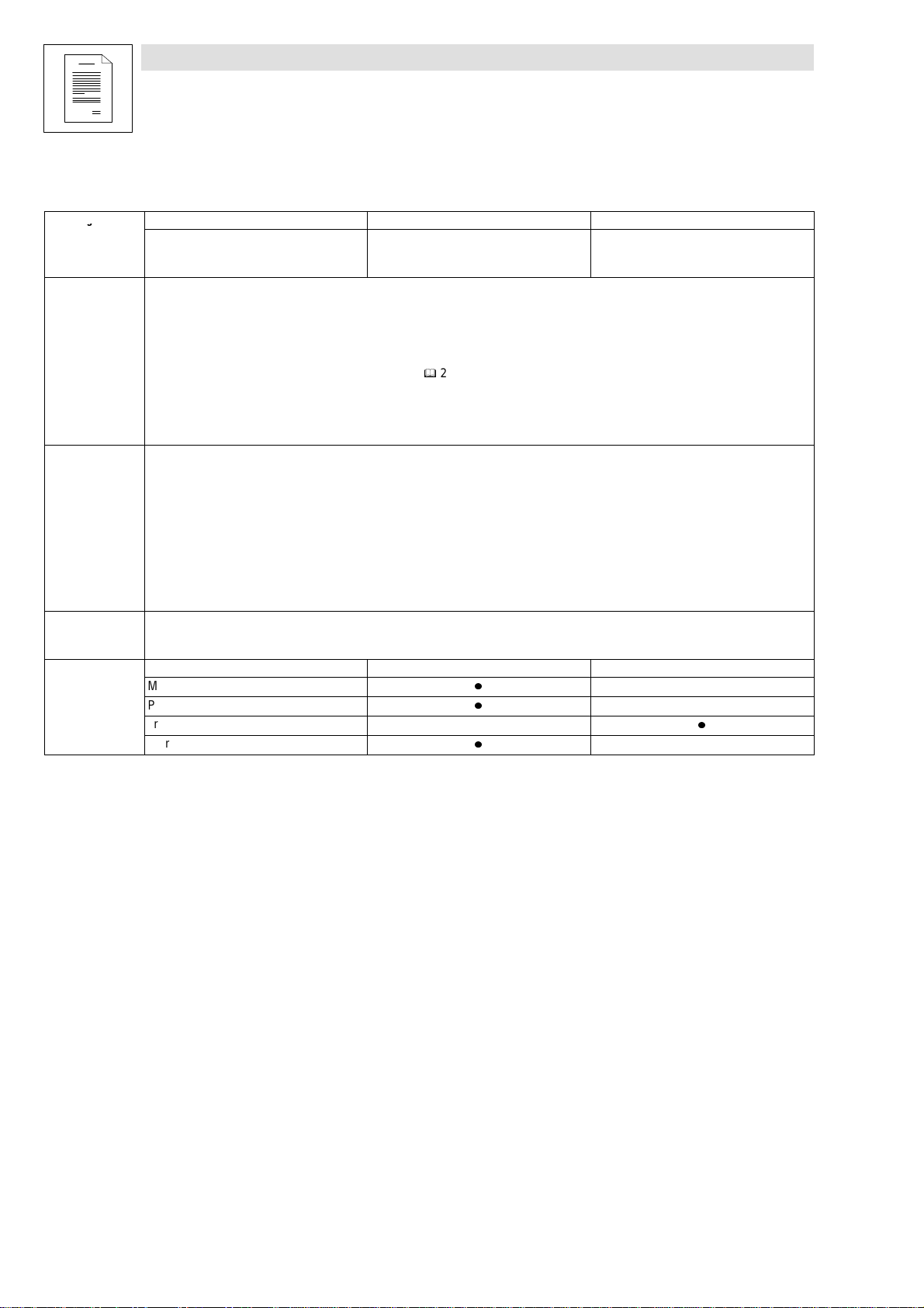
Disposal
Material recycle dispose
Me ta l
Pla sti c
Printe d-board asse mblies
Short Instructions/Operating Instructions
-
-
-
-
-
-
-
1-2
BA2112EN
Page 7

Safety information
Show/Hide Bookmarks
2 Safety information
2.1 Persons responsible for safety
Operator
• An ope rator is a ny natural or legal person who uses the drive system or on behalf of whom t he drive system is used.
• The operator or his safety personne l is oblige d
– to ensure the compliance wi th all re levant re gulations, instructions a nd legislat ion.
– to ensure that only skilled personnel work s on and with the2102IB fieldbus module.
– to ensure that the pe rsonnel ha s the Opera ting Instructions ava ilable for all corresponding work .
– to ensure that a ll unqualified personne l are prohibited from work ing on a nd with the drive system.
Qualified p ersonnel
Qualified personnel are pe rsons who - be cause of their e ducation, experie nce, instructions, and knowledge about corresponding sta ndards a nd regulations, rules for
the prevention of accidents, a nd opera ting conditions - are authoriz ed by the person responsible for the sa fety of the plant to perform the require d actions a nd who are
able to recognize pot ential ha zards.
(Definition for qua lifie d personne l to VDE 105 or IEC 364)
2.2 General safety information
• These safety note s do not claim t o be complete. In case of questions and problems please contact your Lenz e representat ive.
• At the time of delivery the fieldbus module meets the sta te of the a rt and ensures ba sically safe opera tion.
• The indications given in the se Operating Instructions refer to the st ated hardware and software versions of the fieldbus module s.
• The fieldbus module is hazardous if:
– unqualified personnel works on and with t he fieldbus module.
– the fieldbus module is used ina ppropriately.
• The processing notes and circuit sections shown in the se Operating Instructions are proposa ls which ca nnot be transferred to other applica tions without being
tested and checked.
• Ensure by a ppropriate me asures that neither personal injury nor damage to property ma y occur in the event of failure of the fieldbus module.
• The drive syste m must only be operated when no faults occur.
• Retrofitti ngs, modificat ions, or redesigns are basically prohibite d.Lenze must be contacted in all case s.
• The fieldbus module is electrica l equipment intended for use in industria l high- power plants. The fieldbus module must be tightly screwed to the corresponding
controller during operation. In addition, all measures described in the Operating Instructions of the controller used must be taken. Example: Fasten cove rs to ensure
protection aga inst contact.
BA2112EN
2-1
Page 8
Safety information
Show/Hide Bookmarks
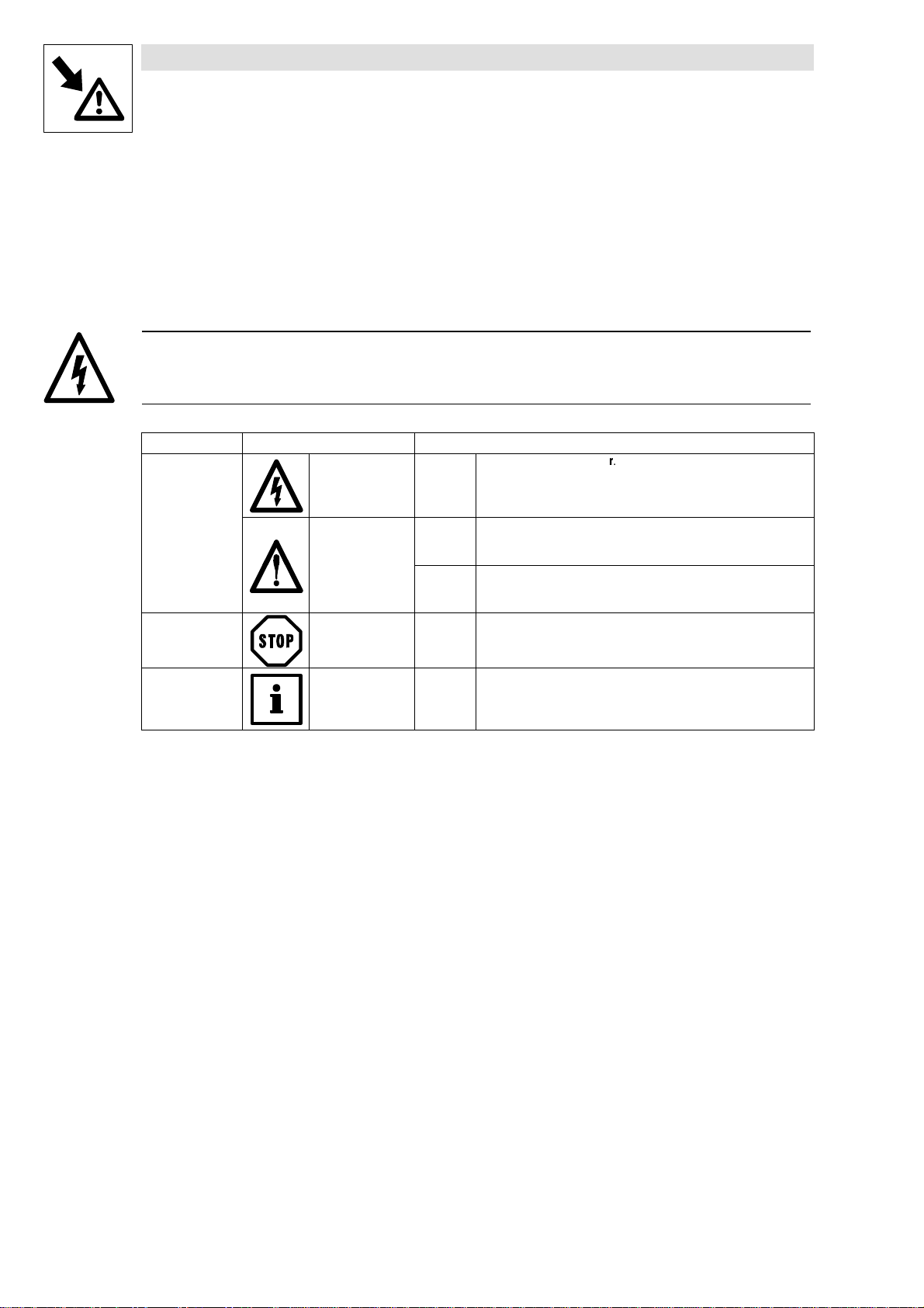
2.3 Layou t of the safety information
• All safety information has a uniform layout:
– The icon characterizes the type of danger.
– The signal word characterizes the severity of danger.
– The note text describes the danger and gives information on how to prevent dangerous
situations.
Signal word
Note
Icons used Signal words
Wa rn i ng o f
damage to
persons
Wa r n i n g o f
hazardous e lectrical
volta ge
Danger! Wa r n s o f impending dangeU.
Consequences if disregarded:
Death or severe injuries.
Warning of a general
danger
Wa rn i ng o f
damage to
material
Other no tes Tip! This note de signates general, use ful not es.
Warning! Wa r ns of potential, very hazardous situations.
Possible consequences if disregarded:
Death or severe injuries.
Caution! War n s o f potential, hazardous situations.
Possible consequences if disregarded:
Light or minor injuries.
Stop! Wa r n s o f potential damage to material.
Possible consequences if disregarded:
Damage of the controller/drive system or its environment.
If you observe it, handling of the cont roller/drive system i s made
easier.
2-2
BA2112EN
Page 9
Technical data
Show/Hide Bookmarks
3 Technical data
3.1 Features
• Attachable additional module for Lenze controller series 82XX, 8200 vector, and 93XX
• Bus connection via remote bus to RS485 standard
• Maximum distance between participants: 20 m
• Max. loop length: 200 m
• Variable process d ata configuration
3.2 General data and application conditions
Field Values
Order designation EMF2112IB
INTERBUS pa rticipa nt Slave
Drive profile DRIVECOM profile 20
Baud rate 500 kbit/s
Ambient temperature During operation: 0Cto55C
Transport: -25
Storage: -25
Permissible humidity Class 3K3 to EN 50178 (without conde nsation, average relative humidity 85%)
Cto 70C
Cto 60C
BA2112EN
3-1
Page 10
Technical data
Show/Hide Bookmarks
3.3 Rated data
Field Values
Communication me dium ASIC LPCII
Supply voltage Voltage supply via INTERBUS- Loop.
Insulat ion voltage - bus systems:
• to PE 50 V AC
• to e xternal supply (terminal 39/59) 0V (no electrical isolation)
• to power stage
– 820X / 821X 270 V AC (single basic insulation)
– 822X / 93XX / 8200 vector 270 V AC (double basic insulation)
• to the control terminals
– 8200 vector 100 V AC (single basic insulation)
– 820X 0V (no electrical isolation)
– 821X 50 V AC (electrical isolation)
– 822X / 93XX 270 V AC (single basic insulation)
• to e xternal bus system 0V (no electrical isolation)
Degree of pollution VDE 0110 part 2 pollution degree 2
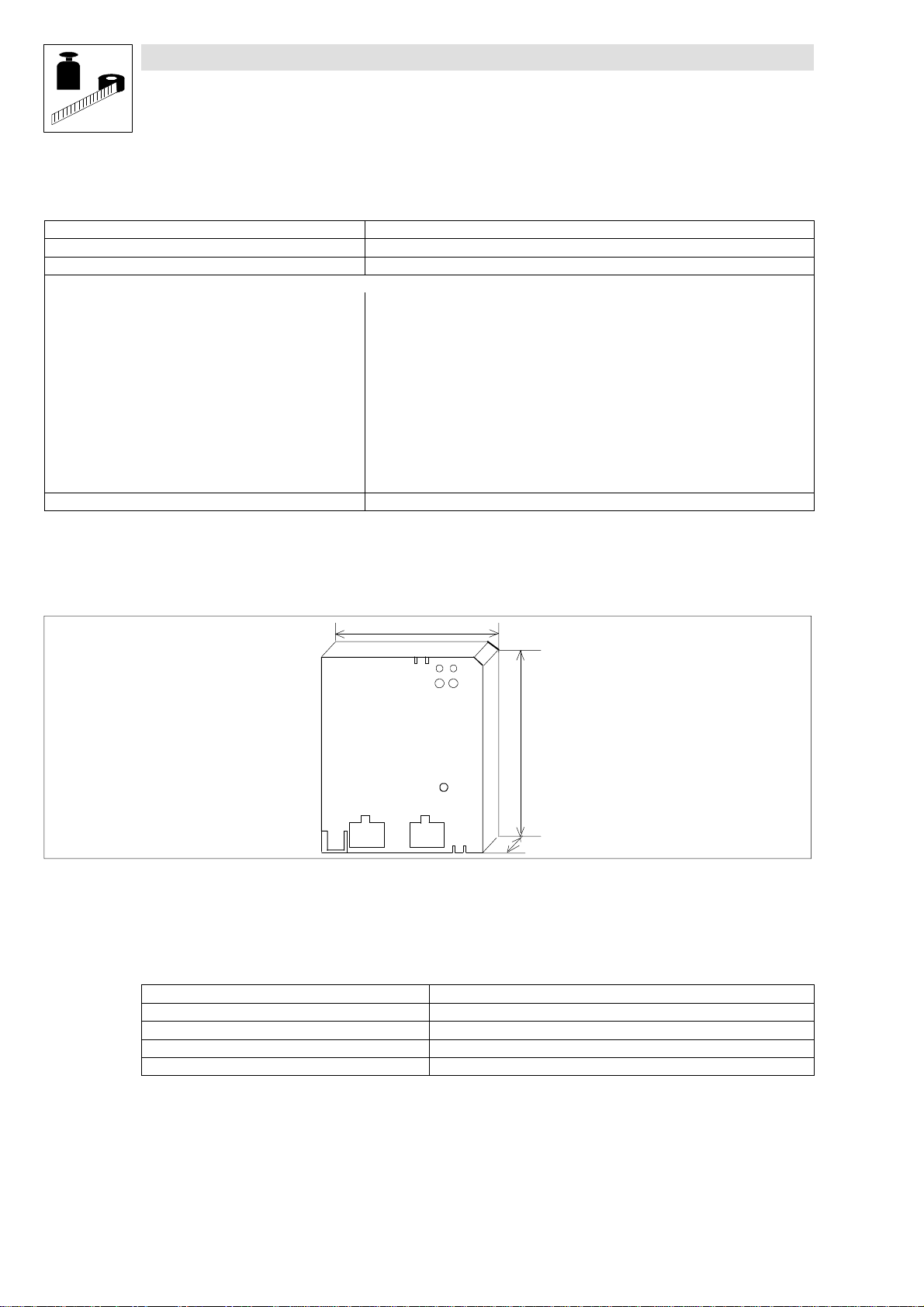
3.4 Dimens ions
Fig. 3-1 Dimensions of the 2112 fieldbus module
3.5 Protocol data
Field Values
Maximum number of controllers with InterBus-Loop 2112 36
Process- data words (PCD): 2 words (32 bit)
INTERBUS-Loop identification 179 (decimal) or B3 (hex)
Baud rate 500 kbit/s
61.8
INTERBUS loop
IN OUT
75.2
2112
18
3-2
BA2112EN
Page 11
3.6 Communication data
Show/Hide Bookmarks
3.6.1 Processing time of the controller
The INTERBUS transfer time or cycle time is added to the processing time in the controller.
The processing time of the controller depends on the controller series and type. Thecycle time of
the bus system is independent of the processing time of the controller.
Processing time 820X
For the 820X series several processing steps are required. These steps are processed cyclically.
A processing cycle consists of:
• Writing the control word or setpoint, if the value has changed
• Alternating reading of status word and actual value
If the time tolerances caused by cyclic reading of the status word/actual value are too large, the
alternating readingof thestatusword and theactual valuecan be suppressed. This is controlled by
the bit 15 (PEinhibit) of the DRIV ECOM control word:
• PEinhibit = 0: S tatus and actual-value update active
• PEinhibit = 1: S tatus and actual-value update inactive
In the following table you will find a list of the processing times:
Processing step Max. processing time in ms Processing tolerance in ms
Setpoint
Control word
Actual value
Status word
Setpoint + control word 70 -16
Setpoint + control word +
actual value + status word
35 -8
140 -32
Technical data
Note:
A change of the setpoint signal results in writing the control word.
Processing time 821X / 8200 vector / 822X
• Process data: approx. 3 ms + 2 ms tolerance
Processing time 93XX
• Process data: approx. 3 ms + 2 ms tolerance
3.6.2 Number of participants
• The maximum number of participants in the INTERBUS-Loop is 63.
Tip!
The maximum number of participants is not always possible. The number of fieldbus modules
(participants)taking part in the communication is limited by the sum of their partial currents.
The sum current limit is I
Example
The INTERBUS-Loop is loaded with approx. 50 mA per controller connected.
Here the sum current of I
max
max
=1.8A.
= 1.8 A is reached when 36 controllers are connected.
BA2112EN
3-3
Page 12

Technical data
Show/Hide Bookmarks
3-4
BA2112EN
Page 13

4 Installation
1
Show/Hide Bookmarks
4.1 Connections of the fieldbus module 2112
2
No. Name/Meaning
Yellow b us LED Stat us: Bus c ommunicati on
ON Fie ldbus module 2112 has been initialized
OFF Fie ldbus module 2112 is not supplied wi th volt age yet.
BLINKING
(4 Hz )
BLINKING
(2 Hz )
BLINKING
(0. 5 Hz )
Green LED
ON 2112 fieldbus module is suppli ed wi th volt age a nd is conne cted to the cont rolle r.
OFF The 2112 fieldbus modul e is suppl ied via INTERBUS-Loop.X
BLINKING 2112 fieldbus module is suppli ed wi th volt age but i s not c onnected t o the cont roller.
2
1
INTERBUS loop
IN OUT
6
INTERBUS communi cation w ith the mast er is possibl e.
Periphe ral f ault/ open cir cuit
Voltage s upply from t he INTERBUS-Loop, but no INTERBUS communica tion.
Voltage s upply if INTERBUS communic ation is a ctive . Error t elegra ms caused by, e. g. open ci rcuit, a re ge nerat ed.
• Module not connecte d to t he contr oller or
• initializationactive.
Voltage s upply (5 V) from INTERBUS-Loop, but no INTERBUS communica tion.
Control ler i s
• switched-off,
• be ing init ializ ed or
• not a vailable
5
7
2112
3
4
Fig. 4-1 Name/meaning of the module elements
Installation
3
Green LED or red LED
Operating status of the controllers 82XX, 8200 vector and 93XX. (See Operating Instructions for the controller)
4
Fixing screw for fieldbus module
5
INTERBUS-Loop input (IN)
6
INTERBUS-Loop out put (OUT)
7
BA2112EN
4-1
Page 14
Installation
Show/Hide Bookmarks
4.2 Mechanical installation
• If necessary, remove the keypad which was previously attached to the controller before.
• Plug the 2112 fieldbus module into the corresponding interface of the controller and fasten it
with the fixing screw (see Fig. 4-1).
Tighten t he screws t o ensure a good PEconnection.
4.3 Electrical installation
Tip!
Thecommunciationof 820X and 821Xcontrollers may be disrupted by electromagnetic radiation.
If necessary, use an additional PE screen cable.
4.3.1 Voltage supply
No special or external voltage supplies necessary. The 2112 fieldbus module is supplied via
INTERBUS-Loop.
4.3.2 Features:
Communication me dium INTERBUS-Loop
Network topology Ri ng
Possible number of controllers – Max. load capacity of the loops: 1.8 A
Max. loop length 200 m
Distance between fieldbus modules 20 m
Maximum baud rate 500 kbit/s
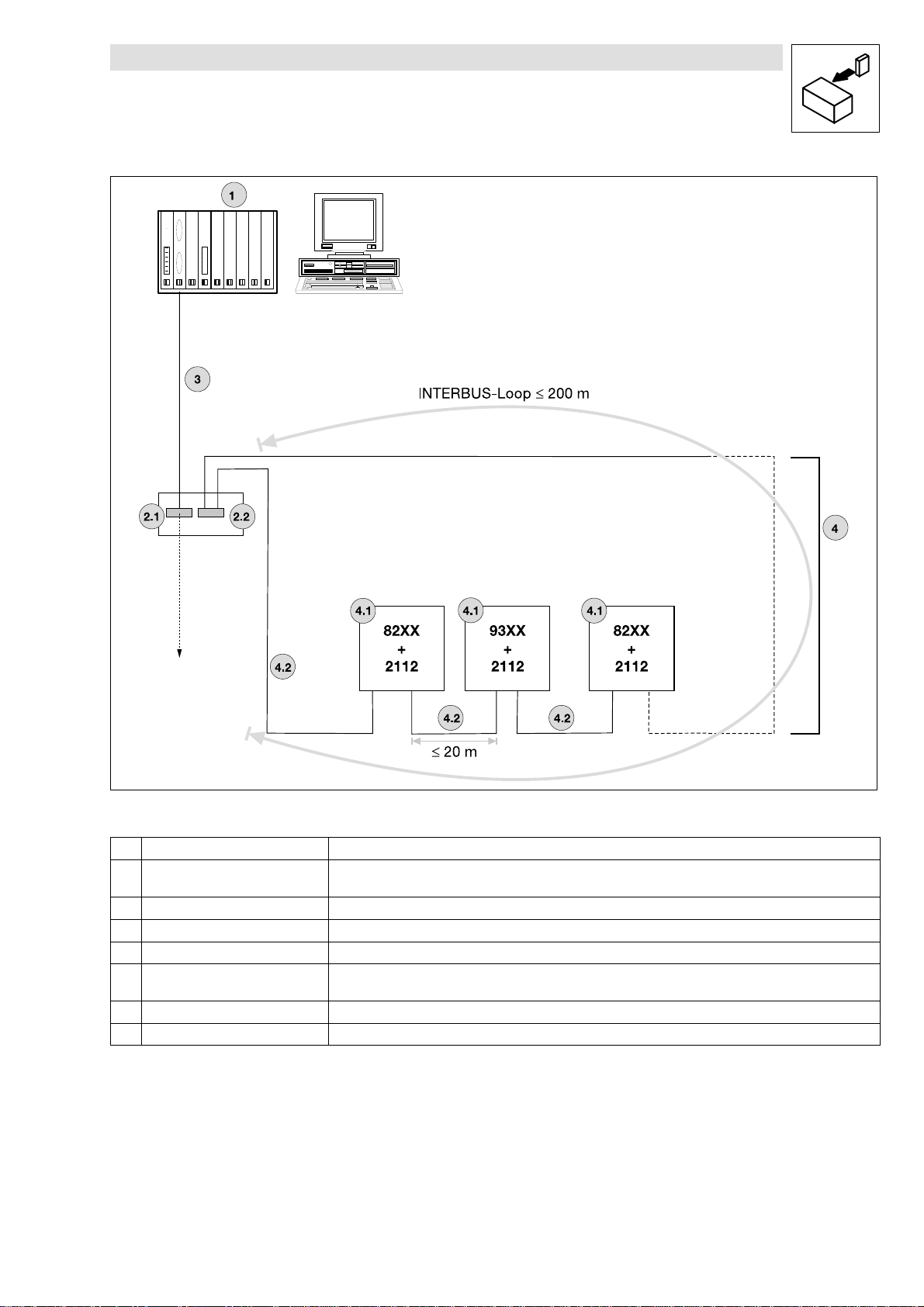
For an example of the INTERBUS structure, see the drawing ( Fig. 4-2). The accessories required
(I NTERBUS Loop terminal) are listed in chapter 8.
– Current consumption per 2112 fieldbus
module:
Å
Max. number of participa nts: 36
50 mA
4-2
BA2112EN
Page 15
Installation
Show/Hide Bookmarks
Fig.4-2 Wiring examplefor the bus system INTERBUS-Loop
Pos . Element Function
1 Host (e.g. PC or PLC) with INTERBUS
master interface module
2.1 Bus terminal Connects a remote bus to the INTERBUS-Loop terminal
2.2 INTERBUS- Loop terminal Start / end of INTERBUS-Loop
3 Remote bus Connects the INTERBUS master module with t he bus termina l and/or other remote bus modules.
4 INTERBUS-Loop INTERBUS-Loop terminal and periphera l bus participants
4.1 INTERBUS- Loop fie ldbus module Bus participant in the INTERBUS-Loop; e .g. Le nze controlle r with INTERBUS-Loop module 2112
4.2 INTERBUS- Loop cable Conne ction in the loop
Ma ste r
(Max. numbe r of participa nts: 63, ma x. sum current < 1.8 A)
2112IBL001
BA2112EN
4-3
Page 16

Installation
Show/Hide Bookmarks
4-4
BA2112EN
Page 17
Commissioning
Show/Hide Bookmarks
5 Commissioning
Stop!
• Before switching on the mains voltage, check the wiring for completeness, earth fault and
short circuit.
• Keep to the switch-on sequence! (Chapters 5.1 to 5.4)
5.1 Configuration of the host for communication with the 2112 fieldbus module
With INTER BUS-Loop the master does not have to be configured. Please observe that a 4th
generation master is used for the communication between host and 2112 fieldbus module.
5.2 Commissioning of 2112 fieldbus modules
1. Plug the 2112 fieldbus module into the front automation interface (AIF)of the controller (see
Operating Instructions for the controller)
2. Supply INTERBUS-Loop terminal (see Fig. 4-2, pos. 2.2) with voltage.
– The green LED for voltage supply (
– An internal initialization between controller and 2112 fieldbus module follows as soon as the
fieldbus module is connected to the controller. The initialization time is up to 3s.
3. Initialization is completed when
– the green LED (
4. ActivateINTERBUS
– the yellow bus LED is on permanently
5. It is now possible to communicate with the drive.
If the LED is not on or blinking, see chapter 7 ”Troubleshooting and fault elimination”.
(4-1) , pos. 1) is on permanently
Tip !
(I f the DRIVE CO M-Profile (C0009 ≠ 11, 12 (
When attaching the fieldbus module to the 93XX controller, the controller is inhibited and the
DRIV ECOM status switch-on inhibit is set. For enabling the controller, the status OPERAT I O N
ENABLE must be set once with the DRIVECOM control word.
can be controlled as usual, e.g. via terminals.
(4-1) pos.1)must be on or blinking.
5-4) ) is selected under C009)
(5-3) . Afterwards, the controller
BA2112EN
5-1
Page 18

Commissioning
Show/Hide Bookmarks
5.3 Drive control via INTERBUS-Loop
82XX /
8200 vector
93XX 1. For drive control via INTERBUS set the Lenze parameter Signal Configuration (C0005) to a value xxx3 using the 9371 keypad. For the first
1. For drive control via INTERBUS, change the setting of the Lenze parameter operating mode (C0001) from 0 to 3.
2. Determina tion of the control mode
– DRIVECOM control (C0009 ≠ 11, 12)
– Unit control (C0009 = 11)
– User defined control profile (C0009 = 12)
Note: Impermissible f or 82XX cont rollers, see
3. Termina l 28 (ctrl. enable ) is always active and must be set to HIGH level during INTERBUS opera tion (see the Operating Instructions for the
controller).
– Otherwise, the controller cannot be e nabled by the INTERBUS (DRIVECOM/standard unit status ”OPERATION ENABLED”).
– With 821x and 822x the QSP function (quick stop) is always active. If QSP is assigned to an input t erminal (default setting: not assigned),
this terminal must be at HIGH le vel during INTERBUS- Loop opera tion (see the corresponding Opera ting Instructions).
The controller now a ccepts control data from the InterBus-Loop.
commissioning, select the signal configuration 1013.
2. Determina tion of the control mode
– DRIVECOM control (C0009
– Unit control (C0009 = 11)
– User defined control profile (C0009 = 12)
3. Set the parameter Start Option (C0142) to 0.
4. Termina l 28 (ctrl. enable ) is always active and must be set to HIGH level during INTERBUS opera tion (see the Operating Instructions for the
controller).
– Otherwise, the controller cannot be e nabled by the INTERBUS (DRIVECOM/standard unit status ”OPERATION ENABLED”).
– With the signal configuration C0005= 1013, the QSP function (quick stop) and the CW/CCW changeover are assigned to the input terminals
E1 a nd E2, and are thus always active. For INTERBUS opera tion E1 must be set to HIGH level (see Operating Instructions 93xx).
The controller now a ccepts control data from t he INTERBUS- Loop.
≠ 11, 12)
5-5 !
5-2
BA2112EN
Page 19

5.4 Enable controller via INTERBUS-Loop
y
p
off
Show/Hide Bookmarks
The2112fieldbusmoduleofferstheuserthepossibilityto operatethe controllerwithdifferentcontrol
modes:
• Standard unit control
• DRIVECOM control
• User defined control profile
The bit assignment of the control and status word depends on the control mode selected. The
selection between the control modes “Standard unit control” and “DRIVECOM control” is effected
via the paramter C0009 of the basic unit and canbe adjusted directly at the controller by meansof
the corresponding keypad.
Auserdefinedcontrol profile canbe generated bysettingC0009 = 12.It isthus possible to map the
2 process data words of the INTERBUS-Loop to the words W1 and W2 of 93XXand 8200 vector
controllers.
Commissioning
C0009 Ty pe Status
11 82XX / 8200 vector / 93XX
12 93XX / 8200 vector
How toenable thecontrollerdependsonthecontrolmode selected and is decribed in thefollowing.
5.4.1 Standard unit control
1. Controller settings as described in chapter 5.3
2. Preselection of standard unit control: Parameter C0009 = 11
3. Input for unit control word: “0000 0000 0000 0000
Å Status change to: “OPERATION ENABLED“
4. The controller is enabled.
Danger!
Ifaspeedhas beenselected in process dataword 2,the drivestarts immediatelywhenthemodule
is being attached.
DRIVECOM:
Process data assignment
PCD 1 PCD 2
Unit control word C0135 or
unit status word C0150
AIF-IN.W1 or
AIF-OUT.W1
bin(0hex
AIF-IN.W1 or
AIF-OUT.W1
AIF-IN.W2 or
AIF-OUT.W2
)”
BA2112EN
5-3
Page 20

Commissioning
Show/Hide Bookmarks
5.4.2 DRIVECOM control
Tip !
• Assoon asthefieldbusmodule isattached to the 93XXcontroller, the c ontroller isinhibited.
DRIVECOM sets the status SWITCH-ON INHIBIT.
• Points 1. to 5. (see below):
– For enabling the controller, the status OPERATION ENABLE must be set once through the
DRIVECOM control word.
– The controllers 821X, 8200 vector and 822X need a speed setpoint to be enabled. These
controllers should therefore have a speed setpoint preselected via the corresponding
process data assignment before they are enabled through 7E
1. Controller settings as described in chapter 5.3
2. DRIVECOM unit control preselection under parameter C0009 ≠ 11, 12
3. Change to status „READY FOR SWITCH ON“
DRIV ECOM control word = 0000 0000 0111 1110
4. Change to the status „OPERATION ENABLED“
DRIV ECOM control word = 0000 0000 0111 1111
(waiting for OPERATION ENABLED)
5. The controller is enabled.
bin
bin
(7E
(7F
hex
hex
hex
or 7F
hex
.
).
)
5.4.2.1 Create DRIVECOM compatibility(C0009 ≠11, 12)
The unit control is described in t he DRIVECOM profile 20. In the following, you will find the changes require d for the Le nze controllers.
820X 821X,
8200 vector
and 822X
93XX Set a DRIVECOM speed signal configuration under code C0005, e. g.:
The automatic DC-injection brake must be deactivated in all parameter sets, i. e.
• C0106=0
• C2106=0
• C4106=0 (only 8200 vector)
• C6106=0 (only 8200 vector)
If the automatic DC-injection brake is not deactivated (holding time of the DC-injection brake C0106 unequal 0), the controller automatically
switches from the status ”OPERATION ENABLED” to the status ”SWITCHED ON” when the spe ed is 0 a nd the holding time of the DC-injection
brak e is elapsed. If the setpoint is higher than 0, the controller is automatically reset to the status ”OPERATION ENABLED”.
• C0005=1013
This configuration corresponds to the signa l configuration 1000 with the following changes:
• Setpoint se lection via INTERBUS- Loop
• Unit control via INTERBUS-Loop
• Output X5.A1 is se lected a s volta ge output for the internal supply of the digital inputs.
• Actual va lues a nd status signa ls for INTERBUS-Loop
For t he detailed description of the signal configuration, see 93XX Manual.
5-4
BA2112EN
Page 21

Commissioning
Show/Hide Bookmarks
5.4.3 Userdefined control profile
The controllers 93XX and 8200 vector offer the possibility to link the process data words 1 and 2
through the AIF block (see Process Data Assignment for 93XX and 8200 vector):
1. Controller settings as described in chapter 5.3
2. Selection of user defined control profile with C0009 = 12
3. Automatic enabling.
Danger!
User-defined control is only allowed for 93XXand 8200 vector controllers!
Ifaspeed hasbeenselected viathe corresponding process dataword,the drivestartsimmediately
when the module is being attached.
5.5 Special features with 82XX, 8200 vector und 93XX
Please note
• For sa fe ope ration it is absolutely necessary to observe the notes f or the controlle rs given in this chapter.
820X • Para me ter se tting only by using the k eypad a nd when the controller is inhibited (DRIVECOM controller sta tus not “OPERATION ENABLED“).
8200 vector • Digital and ana log input and output signals can be freely configured (see Operating Instructions for 8200 vector; codes C0410, C0412, C0417
93XX • Instead of operating mode L-C0001, set signal configuration C0005= xxx3.
• A TRIP must only be reset through INTERBUS Loop:
If the controller is set to the status TRIP while being operated with INTERBUS control (C0001 = 3) and if the TRIP is reset via terminal 28, the
drive might start for a short t ime. When resetting a fault via INTERBUS, this does not occur.
• Afte r the command „TRIP reset“ the 820X controller is basically initialized. During this time the controller does not accept any services.
• Always send the direction of rotation with a low setpoint before the new setpoint:
If the setpoint and the direction of rotation are changed at the sa me time via the DRIVECOM spe ed setpoint, the spe ed ca n change to the
wrong direction or rota tion for a short time. This is because the setpoint is sent to the controlle r as unipola r value before the informat ion about
the direction of rotation is sent.
and C0421)
• Process data words are preconfigured in the controller with C0001 = 3
• A change of code C0005 to xxx3 sta rts the pre configuration of the process da ta words in the controlle r
• Set the parameter C0142 = 0 (auto start lock), to avoid a brief start of the drive during the initialization phase.
BA2112EN
5-5
Page 22

Commissioning
Show/Hide Bookmarks
5-6
BA2112EN
Page 23

6 Parameter setting
ByteN
POW1Uni
tcontro
lwordC0135DRIVECO
Mcontro
lwordLink:W1toAIF-I
N
POW282XX/8200vector:Speedsetpoint
L
ink:W2toAIF-I
N
Show/Hide Bookmarks
Tip!
PCP communication is not supported.
Parameter data (= Lenze codes)can be changed through a keypad which can be attached to the
controller.
6.1 Process data
6.1.1 Processdata assignment
6.1.1.1 General information
Parameter setting
Process data are cyclically exchanged between the controller and the master.
They are subdivided into
• Process output data (PO data)
• Process input data (PIdata)
Here the data flow starts from the master, i.e. the PO data of the master are input data for the
controller.
The controllergets the controlinformation from themaster and returns status information.
Control word and status word
The controller status, such as READY FOR OPERATION, OPERATION ENABLED, etc. a re cont rolled and monitore d via the cont rol and sta tus
words. The range s are subdivided as follows:
• Control word
– The control word is sent from the ma ster t o the controller. It includes sta tus information such as OPERATION ENABLED (see cha pter 5.4).
• Status word
– The status word is se nt from the controller to the ma ster. It provide s all a ctual controller state s, such as ERROR.
INTERBUS-Loop can transfer a maximum of 32 bit, which are interpreted by the 2112 fieldbus
moduleastwo process data words. Theassignment of the processdata words can bepreselected
under code C0009.
Assignment of process output data words
o.
1 HIGH byte ; bit 8- 15
2 LOW byte; bit 0-7
1 HIGH byte ; bit 8- 15
2 LOW byte; bit 0-7
Uni t co ntrol DRIVECOM control User defined
C0009 = 11 C0009 ≠ 11, 12 C0009 = 12
82XX / 8200 vector: Speed setpoint
93XX: Freely configurable
control profile
(only 8200 vector and 93XX)
-
-
BA2112EN
6-1
Page 24

Parameter setting
PIW1DRIVECO
Mstat
ordDRIVECOMstat
ordLink:W1toAIF-OUT
PIW282XX/8200vector:Actualspeed
L
ink:W2toAIF-OUT
Show/Hide Bookmarks
Assignment of process input data words
Byte No.
1 HIGH byte; bi t 8-1 5
2 LOW byte; bit 0-7
1 HIGH byte; bi t 8-1 5
2 LOW byte; bit 0-7
82XX / 8200 vector: Actual speed
93XX: Freely configurable
6.1.1.2 Process-data assignments for 82XX
Structure of t he PO-data response (data to drive)
Byte 1 Byte 2 Byte 3 Byte 4
Control word
High byte
Uni t co ntrol
C0009 = 11
us w
Control word
Low byte
Meaning for
DRIVECOM c ont rol
C0009
us w
Setpoint
High byte
≠ 11, 12
User defined
control profile
C0009 = 12
(only 8200 vector / 93XX)
Setpoint
Low byte
Control w o rd: see chapter 6.1.3.2
Setpoint: frequency setpoint
Here the frequency setpoint is preselected as process data word. The normalization is here
indicated as signed value with
á
24000 =á480 Hz.
Structure of the PI data response (data from drive)
Byte 1 Byte 2 Byte 3 Byte 4
Status word
High byte
Status word
Low byte
Actual value
High byte
Actual value
Low byte
Status word: see chapter 6.1.3.3.
Actual value: act. frequency value
á
The actual frequency value is provided as signed normalization
24000 =á480 Hz.
6-2
BA2112EN
Page 25

Parameter setting
Show/Hide Bookmarks
6.1.1.3 Process-data assignment for 8200 vect or
Digitaland analog inputand output signal canbeconfigured freely (seeOperatingInstructions“8200
vector”: Codes C0410, C0412, C0417 and C0421).
The change of the code C0001 to 3 starts the preconfiguration of the process data words in the
controller (see chapter 5.3,
Structure of t he PO-data response (data to drive)
Byte 1 Byte 2 Byte 3 Byte 4 Byte 5 Byte 6
Control word
High byte
Control word
Low byte
Control w o rd: see chapter 6.1.3.2.
AIF-IN.Wx see C0412.
Structure of the PI data response (data from drive)
Byte 1 Byte 2 Byte 3 Byte 4 Byte 5 Byte 6
Status word
High byte
Status word
Low byte
(5-2) ).
AIF-IN.W1
High byte
AIF-OUT.W1
High byte
AIF-IN.W1
Low byte
AIF-OUT.W1
Low byte
AIF-IN.W2
High byte
AIF-OUT.W2
High byte
AIF-IN.W2
Low byte
AIF-OUT.W2
Low byte
Status word: see chapter 6.1.3.3.
AIF-OUT.Wx see C0421.
Tip!
• Frequency and speed are normalized with á24000 á480 Hz.
• Torque is normalized with 16384 100%.
BA2112EN
6-3
Page 26

Parameter setting
Show/Hide Bookmarks
6.1.1.4 Process-data assignment for 93XX
Withthe 93XXcontroller theprocess dataassignmentcanbechanged by reconfiguring thefunction
blocks AIF-IN and AIF-OUT.
Structure of the PO data response
Byte 1 Byte 2 Byte 3 Byte 4 Byte 5 Byte 6
Control word
High byte
AIF-IN.W1 to AIF-IN.W2 depend on the signal configuration selected under C0005.
For detailed description of the 93XX signal configuration see the Operating Instructions for 93XX
(only the main configurations: 1000, 4000, 5000, etc.) or the Manual 93XX.
In the controller, other signals can be assigned to AIF-IN.W1 to AIF-IN.W2. For this, the
function-block configuration - described in the Manual 93XX- is used. The function block AIF-IN
determines the input data of the controller as data interface for the 2112 fieldbus module.
For more detailed information about the function block AIF-IN, see the Manual 93XX.
Speed control 1003 / 1013 / 1113 NSET-N
Torque control 4003 / 4013 / 4113 MCTRL-MADD
DF ma ster 5003 / 5013 / 5113 NSET-N
DF-slave bus 6003 / 6013 / 6113 DFSET- A-TRIM
DF- slave cascade 7003 / 7013 / 7113 DFSET-VP-DIV
Cam profiler 1xxx3 YSET1-FACT Re se rv ed
Positioning 2xxx3 Re se rv ed Res er ve d
vector control 1xx3 / 2xx3 / 3xx3 / 5xx3 / 100x3 NLIM-IN1 Res er ve d
vector control 4xx3 NCTRL-MADD Res er ve d
vector control 6xx3 DFSET- A-TRIM DFSET-N-TRIM
vector control 7xx3 / 8xx3 / 9xx3 DFSET-VP-DIV DFSET-A-TRIM
vector control 100x3 NLIM- IN1 Res er ve d
vector control 110x3 Re se r ve d Re se rv ed
Control word
Low byte
Signal configuration (C0005) AIF-IN.W1 AIF-IN.W2
AIF-IN.W1
High byte
AIF-IN.W1
Low byte
Speed setpoint
100 % = 16383
Torque se tpoint
100 % = 16383
Speed setpoint
100 % = 16383
Phase trimming
DF fa ctor
AIF-IN.W2
High byte
AIF-IN.W2
Low byte
Re se rv ed
Re se rv ed
Re se rv ed
DFSET-N-TRIM
Speed trimming
DFSET-A-TRIM
Phase trimming
6-4
BA2112EN
Page 27

Parameter setting
. . .. . .
. . .. . .
Show/Hide Bookmarks
A IF -IN *
)
AIF-CTRL.B3
AIF-CTRL.B8
AIF-CTRL.B9
AIF-CTRL.B10
AIF-CTRL.B11
Bit 0
16 B it
C ontrol w ord
Bit 15
B y te 3 ,4
X1
B y te 5 ,6
B y te 7 ,8
16 B it
16 B it
16 B it
C 0855/1
16 binary
signals
C 0855/2
16 binary
signals
16 B it
Low W ord
16 B it
H igh W ord
C 0856/1
C 0856/2
C 0856/3
QSP
DISABLE
CINH
TRIP-SET
TRIP-RESET
AIF-C TRL.B0
AIF-C TRL.B1
AIF-C TRL.B2
AIF-C TRL.B4
AIF-C TRL.B5
AIF-C TRL.B6
AIF-C TRL.B7
AIF-CTRL.B12
AIF-CTRL.B13
AIF-CTRL.B14
AIF-CTRL.B15
AIF-IN.B0
AIF-IN.B2
AIF-IN.B14
AIF-IN.B15
AIF-IN.B16
AIF-IN.B17
AIF-IN.B30
AIF-IN.B31
C 0857
Fig. 6-1 Function block AIF-IN and AIF-IN
AIF-IN*)is available for the 9300 technology variants: servo inverter, positioning controller and cam profiler as of software
version 2.0). AIF-IN.D2 is new.
AIF-IN
DCTRL
A IF -IN .W 1
A IF -IN .W 2
A IF -IN .W 3
AIF-IN.D1
*)
AIF-C TRL.B3
AIF-C TRL.B8
AIF-C TRL.B9
AIF-C TRL.B10
AIF-C TRL.B11
Bit 0
16 B it
C ontrol w ord
Bit 15
C 0136/3
B y te 3 ,4B y te 5 ,6
X1
B y te 7 ,8
16 B it
16 B it
16 B it
C 0855/1
16 binary
signals
C 0855/2
16 binary
signals
16 Bit
Low W ord
16 Bit
H igh W ord
16 Bit
Low W ord
16 Bit
H igh W ord
C 0856/1
C 1197
C 0856/2
C 0856/3
C 0857
DCTRL
QSP
DISABLE
CINH
TRIP-SET
TRIP-RESET
AIF-C TRL.B0
AIF-C TRL.B1
AIF-C TRL.B2
AIF-C TRL.B4
AIF-C TRL.B5
AIF-C TRL.B6
AIF-C TRL.B7
AIF-CTRL.B12
AIF-CTRL.B13
AIF-CTRL.B14
AIF-CTRL.B15
AIF-IN.W 1
AIF-IN.D2
A IF -IN .W 2
AIF-IN.W 3
A IF -IN .B 0
A IF -IN .B 2
A IF -IN .B 1 4
A IF -IN .B 1 5
A IF -IN .B 1 6
A IF -IN .B 1 7
A IF -IN .B 3 0
A IF -IN .B 3 1
AIF-IN.D1
2111IBU003
BA2112EN
Tip!
Please observe that bytes 7 and 8 shown in the diagram above cannot be accessed via
INTERBUS-Loop.
6-5
Page 28

Parameter setting
Show/Hide Bookmarks
Structure of the PI data response (data from drive)
Byte 1 Byte 2 Byte 3 Byte 4 Byte 5 Byte 6
DRIVECOM
Status word
High byte
AIF-OUT.W1 to AIF-OUT.W2 depend on the signal configuration selected under C0005.
For detailed description of the 93XX signal configuration see the Operating Instructions for 93XX
(only the main configurations: 1000, 4000, 5000, etc.) or the Manual 93XX.
In the controller, other signals can be assigned to AIF-OUT.W1 to AIF-OUT.W2. For this, the
function-block configuration- described in the Manual 93XX- is used. The function block AIF-OUT
determines the controller output data as data interface for the 2112 fieldbus module.
For more detailed information about the function block AIF-OUT, see the Manual 93XX.
Speed control 1003 / 1013 / 1113 MCTRL-NACT
Torque control 4003 / 4013 / 4113 MCTRL-MSET2
DF ma ster 5003 / 5013 / 5113 MCTRL-NACT
DF-slave bus 6003 / 6013 / 6113 MCTRL-NACT
DF- slave cascade 7003 / 7013 / 7113 MCTRL-NACT
Cam profiler 1xxx3 MCTRL- NACT
Positioning 2xxx3 MCTRL-NACT
vector control 1xx3 / 4xx3 / 5xx3 / 10xx3 MCTRL-NACT
vector control 6xx3 / 7xx3 / 8xx3 / 9xx3 MCTRL- NACT
vector control 110x3 Re se r ve d Re se rv ed
DRIVECOM
Status word
Low byte
Signal configuration (C0005) A IF- OUT.W1 AI F-OUT.W2
AIF-OUT.W1
High byte
AIF-OUT.W1
Low byte
Actual speed
100 % = 16383
Torque display
100 % = 16383
Actual speed
100 % = 16383
Actual speed
100 % = 16383
Actual speed
100 % = 16383
Actual speed
100 % = 16383
Actual speed
100 % = 16383
Actual speed
100 % = 16383
Actual speed
100 % = 16383
AIF-OUT.W2
High byte
AIF-OUT.W2
Low byte
MCTRL-MSET2
Torque display
100 % = 16383
MCTRL- NACT
Act. speed in %
100 % = 16383
MCTRL-MSET2
Torque display
100 % = 16383
MCTRL- PHI-ACT
Actua l phase
MCTRL- PHI-ACT
Actua l phase
Re se rv ed
Re se rv ed
MCTRL- IACT
MCTRL- PHI-ANA
For more detailed information about the function block AIF-OUT, see the Manual 93XX.
6-6
BA2112EN
Page 29

Parameter setting
Show/Hide Bookmarks
AIF-O UT
C 0156/1
C 0156/6
C 0156/7
STAT
STAT.B0
DCTRL-IM P
...
STAT.B14
STAT.B15
16 Bit
B it 0
B it 1 5
B it 0
C 0850/1
C 0850/2
C 0850/3
C 0116/1
C 0116/16
C 0116/17
C 0116/32
C 0851
FDO -0
...
FDO -15
FDO -16
...
FDO -31
AIF-O U T.D 1
C 0858/1
C 0858/2
C 0858/3
FDO
C 0859
AIF-O U T.W 1
AIF-O U T.W 2
AIF-O U T.W 3
16 Bit
Low W ord
16 Bit
H igh W ord
16 Bit
Low W ord
16 Bit
H igh W ord
C 0852
0
1
2
C 0853
0
1
2
B it 1 5
B it 0
B it 3 1
Fig. 6-2 Function block AIF-OUT and AIF-OUT
AIF-OUT*)is available for the 9300 technology variants: servo inverter, positioning controller and cam profiler as of
software version 2.0). AIF-OUT.D2 is new.
AIF-O UT *
STAT
STAT.B0
C 0156/1
DCTRL-IM P
...
STAT.B14
C 0156/6
STAT.B15
Status w ord
B y te 3 ,4
:
B y te 5 ,6
B y te 7 ,8
C 0156/7
C 1195
C 0850/1
C 0850/2
C 0850/3
C 0116/1
C 0116/16
C 0116/17
C 0116/32
C 0851
AIF-O U T.D 2
C 1196
AIF-O U T.W 1
C 0858/1
C 0858/2
C 0858/3
FDO -0
...
FDO -15
FDO -16
...
FDO -31
AIF-O U T.D 1
C 0859
FDO
16 Bit
16 Bit
Low W ord
16 Bit
H igh W ord
AIF-O U T.W 2
AIF-O U T.W 3
16 Bit
Low W ord
16 Bit
H igh W ord
16 Bit
Low W ord
16 Bit
H igh W ord
C 0854
C 0852
C 0853
)
B it 0
Status w ord
B it 1 5
B it 0
0
3
0
1
2
3
0
1
2
B it 1 5
B it 0
B y te 3 ,4
:
B y te 5 ,6
B y te 7 ,8
B it 3 1
2111IBU002
*)
Tip!
Please observe that bytes 7 and 8 shown in the diagram above cannot be accessed via
INTERBUS-Loop.
BA2112EN
6-7
Page 30

Parameter setting
820X821x,822x
1
1=JOG3(C0039)active1
1=JOG3(C0039)activ
U
y
our
o
UseC0410tosetyourow
n
Show/Hide Bookmarks
6.1.2 Unit control (C0009 = 11)
In the following the bit assignment of control and status word is under C0009 = 11:
6.1.2.1 Control word
Control word for 82XX and 8200 vector
820X 821x,822x
Factory setting:
C0001=3 if C0007 < 52
0
JOG1, J OG2, J OG3
00 = C0046 active
01 = JOG1 (C0037) active
10 = JOG2 (C0038) active
1
2 CW/CCW (CW rotation/CCW rotation)
0 = CW rotation
1 = CCW rotation
3 QSP (quick stop)
0 = QSP not active
1=QSPactive
4 Re se r ve d RFG stop (stop of the ra mp function
5 Re se r ve d RFG zero (deceleration along the T i f
6 Re se r ve d UP function for motor potentiometer
7 Re se r ve d DOWN function for motor
8 Re se r ve d Re se rv ed Re se rv ed
9 Ctrl. inhibit (controller inhibit)
0 = controlle r not inhibited
1 = controlle r inhibited
10 Re se r ve d Re se rv ed No function
11 Re se r ve d TRIP rese t
12 PAR1 (Parameter set changeover)
0 -> 1 = Parameter set
1 -> 0 = Parameter set
13 Re se r ve d Re se rv ed DCTRL1-PAR3/4
14 DC brake (DC injection brake)
0 = DC brake not active
1 = DC brake active
15 Re se r ve d Re se rv ed Re se rv ed
JOG1, J OG2, J OG3
00 = C0046 active
01 = JOG1 (C0037) active
10 = JOG2 (C0038) active
e
CW/CCW (CW rotation/CCW rotation)
0 = CW rotation
1 = CCW rotation
QSP (quick stop)
0 = QSP not active
1=QSPactive
generator)
0 = RFG stop not active
1=RFGstopactive
ramp C0013)
0 = RFG zero not active
1=RFGzeroactive
0 = UP not active
1=UPactive
potentiometer
0 = DOWN not a cti ve
1 = DOWN a ctive
Ctrl. inhibit (controller inhibit)
0 = controlle r not inhibited
1 = controlle r inhibited
0 - > 1 = Edge from 0 to 1
PAR1 (Parameter set changeover)
0 -> 1 = Parameter set
1 -> 0 = Parameter set
DC brake (DC injection brake)
0 = DC brake not active
1 = DC brake active
NSET1 -JOG1 /3
00 = C0046 active
01 = JOG1 (C0037) active
10 = JOG2 (C0038) active
11 = JOG3 (C0039) active
NSET1 -JOG2 /3
DCTRL1-CW/CCW
0 = not active
1=active
AIF-CTRL- QSP
0 = not active
1=active
NSET1 -RFG1 -STOP
0 = not active
1=active
NSET1-RFG1-0
0 = not active
1=active
MPOT1 -UP
0 = not active
1=active
MPOT1- DOWN
0 = not active
1=active
AIF-CTRL- CINH
0 = not active
1=active
AI F- CT RL- TRIP -RE SET
0 - > 1 = Edge from 0 to 1
DCTRL1-PAR2/4
0 = not active
1=active
0 = not active
1=active
MCTRL1-DCB
0 = not active
1=active
8200vector
Factory setting:
C001=3 if C0007 > 51
The default setting (see below) is
accepted with setting C0007 > 51
se C0410 toset
configurations.
wn
6-8
BA2112EN
Page 31

Control word for 93XX
Show/Hide Bookmarks
Parameter setting
9300 9300 Servo 9300
C0005 1xx3 4xx3 5xx3 6xx3,7xx3 2xxx3 xxx3 1xxx, 2xxx,
0 NSET-JOG*1 Re se r ve d NSET- JOG*1 Re se rv ed Res er ve d CSEL1-CAM*1 NSET-J OG*1 Re se rv ed Re se r ve d
1 NSET-JOG*2 Re se r ve d NSET- JOG*2 Re se rv ed Res er ve d CSEL1-CAM*2 NSET-J OG*2 Re se rv ed Re se r ve d
2 NSET-N- INV NSET- N-INV NSET-N-INV NS ET-N- INV Re se rve d CSEL1-CAM*4 NSET-N- INV Re se rv ed Re se r ve d
3 AIF-CTRL.QSP AIF-CTRL.QSP AIF- CTRL.QSP AIF-CTRL.QSP AIF- CTRL.QSP AIF-CTRL.QSP AIF-CTRL.QSP AIF-CTRL.QSP AIF- CTRL.QSP
4 NSET-RFG-
STOP
5 NSET-RFG-0 NS ET-RF G-0 NSET-RF G-0 NSET -RFG- 0 POS-PRG-STOP CDATA-CYCLE NSET-RF G-0 NSE T-RFG- 0 Re se rv ed
6 Re se rv ed Re se r ve d Re se rve d Re se r ve d Res er ve d CSEL1- LOAD Re se r ve d Res er ve d Re se rv ed
7 Re se rv ed Re se r ve d Re se rve d Re se r ve d POS-PRG-RESE T CSEL1- LOAD Re se rv ed Res er ve d Re se rv ed
8 Re se rv ed Re se r ve d Re se rve d Re se r ve d Res er ve d Re se r ve d Re se r ve d Res er ve d Re se rv ed
9 AIF- CTRL.CINH AIF-CTRL.CINH AIF- CTRL.CINH AIF-CTRL.CINH AIF- CTRL.CINH AIF-CTRL.CINH AIF-CTRL.CINH AIF- CTRL.CINH AIF-CTRL.CINH
10 AIF-CTRL.TRIP-
SET
11 AIF-CTRL.TRIP-
RES ET
12 DCTRL-PAR*1 DCTRL-PAR*1 DCTRL-PAR*1 DCTRL-PAR*1 POS-PS-CANCEL Re se r ve d DCTRL- PAR*1 DCTRL-PAR*1 DCTRL-PAR*1
13 DCTLR-PAR-
LOAD
14 NSET-Ti*1 NSET -JOG*1 REF - ON REF - ON POS- LOOP-ONH Re se rv ed NSET- Ti*1 NSET- JOG*1 Re se r ve d
15 NSET-Ti*2 NSET -JOG*2 NSET-Ti*1 Rese r ve d POS-STBY-STP Re se r ve d NSET- Ti*2 NSET- JOG*2 Re se rv ed
NSET- RFGSTOP
AIF-CTRL.TRIPSET
AIF-CTRL.TRIPRES ET
DCTLR-PARLOAD
NSET- RFGSTOP
AIF-CTRL.TRIPSET
AIF-CTRL.TRIPRES ET
DCTLR-PARLOAD
NSET- RFGSTOP
AIF-CTRL.TRIPSET
AIF-CTRL.TRIPRES ET
DCTLR-PARLOAD
Pos ition ing
controller
POS-PRG- START CSEL1- EVENT NSET-RFG-
AIF-CTRL.TRIPSET
AI F- CT RL. TRIP- RE
SET
POS -PA RAM- RD Re se rv ed DCTLR-PAR-
9300
Cam profiler
AIF-CTRL.TRIPSET
AI F- CT RL. TRIP- RE
SET
3xxx, 5xxx,
10xxx, 11xxx
STOP
AIF-CTRL.TRIPSET
AIF-CTRL.TRIPRES ET
LOAD
9300 Vector
4xx3 6xx3,7xx3
NSET- RFGSTOP
AIF-CTRL.TRIPSET
AIF-CTRL.TRIPRES ET
DCTLR-PARLOAD
Re se rv ed
AIF-CTRL.TRIPSET
AIF-CTRL.TRIPRES ET
DCTLR-PARLOAD
Tip!
Thesinglebit control commandsof the control word depend onother bit positions. Chapter6.1.3.1
describes the bits required to effect the command.
BA2112EN
6-9
Page 32

Parameter setting
Show/Hide Bookmarks
6.1.2.2 Status word
Status word for 82XX and 8200 vector
820X 821x,822x 8200vector
0 Res er ve d Actual parameter set
1 IMP (pulse i nhibit)
0 = Pulses for power stage enabled
1 = Pulses for power stage inhibited
2 I
3 Res er ve d fd=f
4 fd=f
5 Qmin (f
6 fd= 0 (act. frequency = 0)
7 Ctrl. inhibit (controller inhibit)
8...11 Uni t s ta tu s
(current limit reached)
max
0 = Curre nt limit not re ached
1 = current limit reached
dset
0=f
≠ f
d
dset
1=fd=f
dset
≤ f
)
d
d
d
dQmin
≠ 0
=0
0 = Qmin not active
1=Qminactive
0=f
1=f
0 = controlle r not inhibited
1 = controlle r inhibited
0 = No error
8 = Error active
0=Parameterset1or3active
1=Parameterset2or4active
IMP (pulse inhibit)
0 = Pulses for power stage enabled
1 = Pulses for power stage inhibited
I
(current limit reached)
max
0 = Curre nt limit not re ached
1 = current limit reached
dset
0=f
≠ f
d
dset
1=fd=f
dset
RF G on = RF G of f
0=RFGon
1 = RF G o n = RF G ou t
Qmin (f
0 = Qmin not active
1=Qminactive
fd= 0 (act. frequency = 0)
0=f
1=f
Ctrl. inhibit (controller inhibit)
0 = controlle r not inhibited
1 = controlle r inhibited
Uni t st a tu s
0 = Controller initialization
1 = Switch on inhibit
3 = Operation inhibited
4 = Flying-restart circuit active
5 = DC brake active
6 = Operation enabled
7 = Messa ge a ctive
8 = Fault active
d
d
d
≠ 0
=0
≠ RF G o ff
≤ f
dQmin
)
Lenz e setting
DCTRL-PAR- B0
DCTRL1-IMP
MCTRL1-IMAX
MCTRL1-RFG1= NOUT
NSET1-RFG1-I= 0
PCTRL1-QMIN
DCTRL1-NOUT=0
DCTRL1-CINH
Uni t st a tu s
0 = Controller initialization
1 = Switch on inhibit
3 = Operation inhibited
4 = Flying-restart circuit active
5 = DC brake active
6 = Operation enabled
7 = Messa ge a ctive
8 = Fault active
12 Overtemperature warning ( ϑ
0=Nowarning
1=Warning
13 U
14 Direction of rotation
15 Ready for ope ration
(DC-bus overvoltage)
Gma x
0 = No overvoltage
1 = overvoltage
0 = CW rotation
1 = CCW rotation
0 = not ready f or opera tion
1 = ready for ope ration
max
-10°C)
Overtemperature warning
0=Nowarning
1=Warning
U
(DC-bus overvoltage)
Gma x
0 = No overvoltage
1 = overvoltage
Direction of rotation
0 = CW rotation
1 = CCW rotation
Ready for operation
0 = not ready f or opera tion
1 = ready for ope ration
DCTRL1-OH- WARN
DCTRL1-OV
DCTRL1-CCW
DCTRL1-RDY
6-10
BA2112EN
Page 33

Status word for 93XX
8...1
1
Show/Hide Bookmarks
Parameter setting
9300 Ser vo Servo
C0005 1xx3 4xx3 5xx3 6xx3,7xx3 2xxx3 1xxx3 xxx, 2xxx,
0 DCTRL- PAR1-0 DCTRL-PAR1- 0 DCTRL-PAR1-0 DCTRL-PAR1-0 Re se rv ed CERR1 - ERR DCTRL-PAR1- 0 DCTRL-PAR1-0 DCTRL-PAR1-0
1 DCTRL- IMP DCTRL-IMP DCTRL-IMP DCTRL-IMP DCTRL-IMP DCTRL-IMP DCTRL-IMP DCTRL-IMP DCTRL-IMP
2 MCTRL-IMAX MCTRL-IMAX REF -O K REF - OK POS- REF- OK MCTRL-IMAX MCTRL-IMAX MCTRL-IMAX MCTRL-IMAX
3 MCTRL- MMAX Re se r ved MCT RL -MMAX Re se r ve d Re se r ve d MCT RL -MMAX MC TRL- MMAX MCTRL-IMAX
4 NSET- RFG-I= 0 MCTRL-IMAX
5 QMIN QMIN REF-BUSY REF- BUSY POS-IN-TARGET CDATA-X0 QMIN QMIN QMIN
6 DCTRL- NACT=0DCTRL-NACT=0DCTRL-NACT=0DCTRL-NACT=0DCTRL-NACT=0DCTRL-NACT=0DCTRL-NACT=0DCTRL-NACT=0DCTRL-NACT=
7 DCTRL- CINH DCTRL- CINH DCTRL-CINH DCTRL-CINH DCTRL-CINH DCTRL-CINH DCTRL- CINH DCTRL- CINH DCTRL-CINH
8 ... 11 Controller status:
12 DCTRL- WARN DCTRL-WARN DCTRL-WARN DCTRL-WARN DCTRL-WARN DCTRL-WARN DCTRL-WARN DCTRL-WARN DCTRL-WARN
13 DCTRL-MESS DCTRL- MESS DCTRL-MESS DCTRL-MESS DCTRL-MESS DCTRL-MESS DCTRL-MESS DCTRL-MESS DCTRL-MESS
14 DCTRL-CW/
CCW
15 DCTRL- RDY DCTRL-RDY DCTRL-RDY DCTRL-RDY DCTRL-RDY DCTRL-RDY DCTRL- RDY DCTRL-RDY DCTRL-RDY
negated
DCTRL-CW/
CCW
NSET- RFG- I= 0 MCTRL-IMAX
DCTRL-CW/
CCW
negated
Re se rv ed DCTRL-AIFL-
positioning
controller
MCTRL -MMAX
negated
0=
Unit initialization
1=
Switch-on inhibit
3=
Operation inhibited
4=
Flying-restart circuit active
5=
DC-injection brake active
6=
Operation enabled
7=
Message a ctive
8=
Fault active
10 =
Fail-QSP (only 9300 servo positioning controller)
QSP
Serv o cam
profiler
3xxx, 5xxx,
10xxx, 11xxx
DCTRL-TRIP NSET-RF G-I= 0 NSET- RFG- I=0 NSET- QSP-OUT
DCTRL-CW/
CCW
DCTRL-CW/
CCW
vector
4xxx 6xxx, 7xxx,
negated
DCTRL-CW/
CCW
MCTRL -MMAX
0
DCTRL-CW/
CCW
8xxx, 9xxx
Tip!
Thecurrent controller status canonly be clarified by combining thebits with the status information
(bit 0, 1, 2, 3, 4, 5 and 6). This is shown in chapter 6.1.3.1.
BA2112EN
6-11
Page 34

Parameter setting
Show/Hide Bookmarks
6.1.3 DRIVECOM control (C0009≠ 11, 12)
6.1.3.1 DRIVECOM status machine
Controllers 82XX, 8200 vector (C0001 ½ 3)
For standard control you enter the control information via the corresponding control inputs
(terminal):
Information about the current unit status (Fig. 6-3, see below) (rectangles) are available in the
DRIVECOM parameter “status word“. Commands in theDRIVECOM parameter “control word“ are
switched offandcannotchangethecontrollerstatus.Thecommandsto changethecontrollerstatus
are entered via the corresponding control inputs. These commands are marked by arrows in the
following diagram.
Switch on unit
NOT READY TO SWITCH ON
Status word xxxx xxxx x0xx 0000
automatically when
the initialization is
completed
READY TO SWITCH ON
Status word xxxx xxxx x01x 0001
automatically
SWITCHED ON
Status word xxxx xxxx x01x 0011
Ctrl. enable** Ctrl. inhibit**
OPERATION ENABLED
Status word xxxx xxxx x01x 0111
QSP**
TRIP (fault)
Fault
Status word xxxx xxxx x0xx 1000
TRIP reset**
Note:
The terms marked with ** are
commands
Fig. 6-3 Status diagram for standard unit control
Status Meaning
NOT READY TO SWITCHONThe controller is being initialized a nd is not yet re ady to operate.
READYTOSWITCHON The controller is inhibite d and waits for the powe r stage to be cha rged. It the n automatically switches to the sta tus “SWITCHED ON“.
SWITCHED ON The controlle r is inhibited a nd waits for controlle r ena ble.
OPERATION ENABLED The controlle r is e nabled. In t his status, a pulse inhibit can be set a utomatically.
FAULT The controller is in the status “FAULT“ (T RIP).
6-12
It then automatically switches to the status READY TO SWITCH ON.
BA2112EN
Page 35

Parameter setting
Show/Hide Bookmarks
Controllers 82XX and 8200 vector (C0001 = 3) and 93XX
With INTERBUS-DP control(82XX:Lenze parameter C0001 = 3; 93XX: always)and whenusing the
2112fieldbusmodule, theLenzecontrollerstatusis normalizedaccordingtotheDRIV ECOM-Profile
20.
Information about the current unit status (Fig. 6-4 rectangles in the status diagram)are available in
theDRIVECOM parameter “Status word“. Commands in the DRIV ECOM parameter control word
can change thecontrollerstatus.Thesecommandsaremarked byarrowsinthe following diagram.
Example:
Status information by means of
„status word“
Bit 15 ... bit 0 (binary display)
Switch on unit
FAULTREACTION ACTIVE
Status word xxxx xxxx x0xx 1111
13
Malfunction was recognized
automatically, if the error reaction is over
NOTREADY TO SWITCH ON
Status word xxxx xxxx x0xx 0000
automatically when
initializing is completed
SWITCH ON INHIBIT
Status word xxxx xxxx x0xx 0000
9
Inhibit voltage
xxxx xxxx xxxx xx0x
Status word xxxx xxxx x01x 0001
8
Standstill
xxxx xxxx xxxx
x110
Status word xxxx xxxx x01x 0011
Operation enable
xxxx xxxx xxxx 1111 and
act. speed value
Status word xxxx xxxx x01x 0111
2
Standstill
xxxx xxxx
xxxx x110
READY TO SWITCH ON
3
Switch on
xxxx xxxx
xxxx x111
SWITCHED ON
45
≠0*
OPERATION ENABLED
Inhibit RFG is mapped to
quick stop
Fig. 6- 4 Statusdiagram DRIVECOM unit control
Status word xxxx xxxx x0xx 1000
10
Inhibit voltage
xxxx xxxx xxxx xx0x
Quick stop
xxxx xxxx xxxx x01x
7
6
Standstill
xxxx xxxx xxxx x110
Operation inhibit
xxxx xxxx xxxx 0111 or act.
speed value = 0*
QUICK STOP ACTIVE
Status word xxxx xxxx x01x 0111
11
Quick stop
xxxx xxxx xxxx x01x
Note :
* only valid for 821X, 8200 vector when the automatic
DC-injection brake is active (C0106, C2106
Fault
14
Reset fault
xxxx xxxx 0xxx xxxx
xxxx xxxx 1xxx xxxx
12
Inhibit voltage
xxxx xxxx xxxx xx01
or
quick stop completed
≠ 0)
Status Mea ning
NOTREADYTOSWITCHON The controller is being initialize d and is not yet ready to ope rate. It then automatically switches to the sta tus READY TO SWITCH ON.
SWITCH ON INHIBIT The controller is inhibited and waits f or command 2 (shut down).
READYTOSWITCHON The controller is inhibited and waits f or command 3 (switch on).
SWITCHED ON The controller is inhibited and waits for command 4 (enable opera tion).
OPERATION ENABLED The controller is ena bled. In this status, a pulse inhibit can be set a utomatically.
FAULT REACTION ACTIVE A fault (TRIP) was re cognized and a fa ult re sponse initia ted.
FAULT The controller is in the status “FAULT“ (TRIP).
QUICK ST OP ACTIVE While being in the status “OPERATION ENABLED“ the comma nd “Quick stop“ was set. The controller is decelerated in a controlled
BA2112EN
way (quick- stop ra mp). Afte r deceleration, the controller automatically changes to the controller sta tus “SWITCH ON INHIBIT“.
Theactualunit status canonly be clarified by combining theunit-status informationbits (bit 0 to 6).
This is shown in the following:
6-13
Page 36

Parameter setting
Show/Hide Bookmarks
Uni t st at us Bits of the status word
Bit 6 5 4 3 2 1 0
NOTREADYTOSWITCHON 0 0 0 0 0
SWITCH ON INHIBIT 1 0 0 0 0
READYTOSWITCHON 0 1 0 0 0 1
SWITCHED ON 0 1 0 0 1 1
OPERATION ENABLED 0 1 0 1 1 1
FAULT 0 1 0 0 0
FAULT REACTION ACTIVE 0 1 1 1 1
QUICK ST OP ACTIVE 0 0 0 1 1 1
Switch-on inhibit
Quic k st op
Voltage inhibit
Fault
Operation enabled
Switched on
Readytoswitchon
Command Meaning
COMMAND 2, 6, 8 (standstill)
Control word: bit 0 = 0
COMMA ND 3 (s wit ch o n) Command to change to the controller status “SWITCHED ON“.
COMMAND 4 (enable ope ration) Command to change to the controller status “OPERATION ENABLED“. The cont roller inhibit is deacti vated.
COMMAND 5 (inhibit operation) Command to change to the controller status “SWITCHED ON“. The controlle r inhibit is activated.
COMMAND 7, 9, 10, 12 (voltage inhibit)
Control word: bit 1 = 0
COMMAND 7, 10, 11 (quick stop)
Control word: bit 2 = 0
COMMAND 13 (FAULT/TRIP) The controller ha s recognized a malfunction. For some malfunction a controlle d dece leration ma y be ne cessary
COMMAND 14 (reset fault/TRIP)
A
Control word: bit 7 = 0
1
Command to change from different states to the status „READYTOSWITCHON“.
Command to change to the controller status “SWITCH ON INHIBIT“. The controlle r inhibit is activated.
Command to change to the controller status “SWITCH ON INHIBIT“. If the controller was enabled, it is decelerated in a
controlled way along the Le nze quick- stop ramp.
(depending on the controller). Once completed, the controller cha nges to the status FAULT.
With the series 821X, 8200 vector this command acknowledges a fault. The controller changes to the status “SWITCH ON
INHIBIT“ when a fault is no longer recognized.
6-14
BA2112EN
Page 37

Parameter setting
Show/Hide Bookmarks
The individual bit-control commands of the control word depend on other bit positions. In the
following you will find a description of the bits required to effect the command.
Controller status commands Bits of the control word
Bit 7 6 5 4 3 2 1 0
1 Standsti ll 1 1 0
2Switchon 1 1 1
3 Operation enable 1 1 1 1
4 Operation inhibit 0 1 1 1
5 Voltage inhibit 0
6 Quick st op 0 1
8Faultreset 01
Fault reset
RF G- ze ro
RF G- st op
RFG inhibit
Operation enable
Quic k st op
Voltage inhibit
Switch on
Detailed information on the tables:
0 =Bit statusis 0
1 =Bit statusis 1
no entry = Any bit status, no influence
BA2112EN
6-15
Page 38

Parameter setting
Show/Hide Bookmarks
6.1.3.2 Control word
Bit Name Meaning
0 Switch on 0 = command 2, 6, 8 (controller inhibit)
1 Voltage inhibit 0 = Voltage inhibit active
2 Quic k st op 0 = Quick stop active
3 Operation enable 0 = Operation inhibite d
4 RFG inhibit Inhibit of the ramp-funtion generator.
5 RF G- st op 820X: Reserved
6 RF G- ze ro 820X: Reserved
7 Fault reset Fault reset (TRIP). For this, a bit change from 0 to 1 is require d.
8..9 Rese r ve d
11 Manuf acturer 820X, 821x, 822x: Reserved
12 Manuf acturer 820X, 821x, 822x: Parameter set changeover:
13 Manuf acturer 820X, 821x, 822x: DC-injection brake:
14 Manuf acturer 820X, 821x, 822x: Reserved
15 Manuf acturer 820X: PI - inhibit
1 = command 3 (controller inhibit)
1 = voltage inhi bit not active
1 = Quick stop not active
1 = Operation enabled
Quick stop is activated without the cont roller leaving its sta tus.
0 = RFG inhibit (quick stop)
1 = RFG inhibit not active
821X, 822X: Output of the RFG (speed setpoint integrator) is ”frozen”.
0=RFGstop
1 = RFG stop not active
8200 vector, 93XX: free. Mapping to bit AIF-CTRL.B4 negated.
821X, 822X: Input of the ramp function gene rator (speed setpoint integrator) is set to 0. Thus
controlled deceleration along the ramp.
0=RFGzero
1 = RFG zero not active
8200 vector, 93XX: free. Mapping to bit AIF-CTRL.B5 negated.
For 82XX, the controller is initialized.
During this time, the controller doe s not a ccept any commands.
8200 vector, 93XX: free. Mapping to bit AIF-CTRL.B7 1) .
0 – 1= Parameterset2
1 – 0= Parameterset1
8200 vector, 93XX: free. Mapping to bit AIF-CTRL.B12 1) .
0 = DCB not a ctive
1=DCBactive
8200 vector, 93XX: free. Mapping to bit AIF-CTRL.B13 1) .
8200 vector, 93XX: free. Mapping to bit AIF-CTRL.B14 1) .
Inhibit the update of the PO data of the controller (input data for the ma ster).
Updates for sta tus and actual information of the process channel ca n be inhibited
to transfer control information timed more accurately (see chapter 3.6.2).
0 = Read status and actual value
1 = Do not read status and actual value
821X,822X: Reserved
8200 vector, 93XX: free. Mapping to bit AIF-CTRL.B15 1) .
Signal configuration C0005 Bit 5
Speed control 1003 / 1013 /
Torque
control
DF ma ster 5003 / 5013 /
DF-slave bus 6003 / 6013 /
DF- sla ve
cascade
Cam profiler 1xxx3 CSEL1- EVENT CDATA-CYCLE CSEL1-LOAD Re se rv ed Re se rve d Re ser ve d Re se r ve d
Positioning 2xxx3 POS-PRG-START POS- PRG-S TOP POS- PRG-
1113
4003 / 4013 /
4113
5113
6113
7003 / 7013 /
7113
(AIF-CTRL.B4)
NSET- RFG- STOP
(RFG stop)
NSET- RFG- STOP
(RFG stop)
NSET- RFG- STOP
(RFG stop)
Re se rv ed Re se rv ed Re se r ve d DCTRL-PAR*1 DCTRL-PAR-
Re se rv ed Re se rv ed Re se r ve d DCTRL-PAR*1 DCTRL-PAR-
6-16
Bit 6
(AIF-CTRL.B5)
NSET- RFG- 0
(RF G z e ro)
NSET- RFG- 0
(RF G z e ro)
NSET- RFG- 0
(RF G z e ro)
Bit 11
(AIF-CTRL.B7)
Re se rv ed DCTRL-PAR*1 DCTRL-PAR-
Re se rv ed DCTRL-PAR*1 DCTRL-PAR-
Re se rv ed DCTRL-PAR*1 DCTRL-PAR-
RES ET
Bit 12
(AIF-CTRL.B12)
POS-PS-CANCEL POS- PARA M- RD POS- LOOP-
Bit 13
(AIF-CTRL.B13)
LOAD
LOAD
LOAD
LOAD
LOAD
BA2112EN
Bit 14
(AIF-CTRL.B1
4)
NSETTI*1
NSET- JOG*1 NSET-J OG*2
REF - ON NSET-TI*1
REF - ON Re se rv ed
REF - ON Re se rv ed
INH
Bit 15
(AIF-CTRL.B15)
NSETTI*2
POS-STBY-STP
Page 39

Parameter setting
Show/Hide Bookmarks
Signal configuration C0005 Bit 15
vector control 1xx3 / 2xx3 / 3xx3
/ 5 xx3 / 10xx3
vector control 4xx3 NSET-RFG-STOP
vector control 6xx3 / 7xx3 / 8xx3
/ 9 xx3
vector control 11xx3 Re se rve d Re se rve d Re se r ve d Re se r ve d Re se rv ed Re se rv ed Res er ve d
Bit 5
(AIF-CTRL.B4)
NSET- RFG- STOP
(RFG stop)
(RFG stop)
Re se rv ed Re se rv ed Re se r ve d DCTRL-PAR*1 DCTRL-PAR-
Bit 6
(AIF-CTRL.B5)
NSET- RFG- 0
(RF G z e ro)
NSET- RFG- 0
(RF G z e ro)
Bit 11
(AIF-CTRL.B7)
Re se rv ed DCTRL-PAR*1 DCTRL-PAR-
Re se rv ed DCTRL-PAR*1 DCTRL-PAR-
Bit 12
(AIF-CTRL.B12)
Bit 13
(AIF-CTRL.B13)
LOAD
LOAD
LOAD
Bit 14
(AIF-CTRL.B1
4)
NSET-TI*1 NSET-TI*2
NSET- JOG*1 NSET-J OG*2
Re se rv ed Re se r ve d
(AIF-CTRL.B15)
6.1.3.3 Status word
Bit Name Meanin g
0 Readytoswitchon Controlle r status information
1 Rea dy for ope ration Controller status information
2 Operation enabled Controller status information
3 Fault Controller status information
4 Voltage inhibite d Information about command “Volta ge inhibit“
5 Qui ck stop Information about command “QUICK STOP“
6 Switch-on inhibit Controller sta tus information
7 Wa r n i n g Collective warning
8 Message Colle ctive messa ge. Automatic se tting a nd rese tting of pulse inhibit in the controller status ”OPERATION ENABLED”. Reasons for
9 Re mo te 82xx, 821x, 822x, 8200 vector: Bus access right depends on Lenze parameter ”Operating mode” (C0001)
10 Setpoint reached Status of spee d/freque ncy devia tion
11 Limit value Status of the DRIVECOM speed limitation
12 Res er ve d 820X, 821X, 822X: Reserved
13 Res er ve d 820X, 821x, 822x: Reserved
14 Manufacturer 820X, 821x, 822x: I max (current limit reached)
15 Manufacturer 820X, 821x, 822x: Q min (f d < dQmin )
0 = Sta tus lowe r than “READYTOSWITCHON“
1 = Status at least “SWITCHED ON“
0 = Sta tus lowe r than “READY F OR OPERATION“
1 = Status at least “READY F OR OPERATION“
0 = Sta tus lowe r than “OPERATION ENABLED“
1=Status“OPERATION ENABLED“
0 = No fault (TRIP))
1 = Fault (TRIP) occured
0 = Comma nd active
1 = Command not active
0 = Comma nd active
1 = Command not active
0 = Sta tus not “SWITCH-ON INHIBIT“
1=Status“SWITCH- ON INHIBIT“
0=Nowarning
1=warning
this can be undervolta ge or overvoltage a s well a s overcurrent (clamp).
0 = No me ssage
1 = Me ssa ge (IMP)
0 = C0001
93 XX:
0=RFGon
1 = RF Gon = RF Gof f
always 0
8200 vector, 93XX: Mapping to bit C0150.B14
8200 vector: Mapping to bit C0150.B15
93XX: Mapping to bit C0150.B3
8200 vector, 93XX: Mapping to bit C0150.B2
8200 vector, 93XX: Mapping to bit C0150.B5
1 = C0001 = 3
≠ RF G o ff
0 = Current limit not reached
1 = Current limit exceeded
0 = Q min not active
1=Qminactive
≠ 3
DOZD\V
BA2112EN
6-17
Page 40

Parameter setting
Show/Hide Bookmarks
6.1.4 Userdefined control profile (C0009= 12)
• Only useful with 93XXand 8200 vector (free configuration possible)
• When using a user-defined control profile, predefined control and status words are not
available.
• The user determines the link between input and output data.
• Function block assignment for 93XX (see chapter 6.1.1.4, (
– Byte 3 and 4 form the input or output word W1
– Byte 5 and 6 form the input or output word W2
• Process data assignment for 8200 vector: see chapter 6.1.1.3, (
For more information about the function blocks see the Manuals 93XXand 8200 vector.
Danger!
User-defined control is only allowed for 93XXand 8200 vector controllers!
Ifaspeed hasbeenselected viathe corresponding process dataword,the drivestartsimmediately
when the module is being attached.
6-4) )
6-3) .
Tip!
Please observe that bytes 7/8 of the control/status word shown in the diagram above cannot be
accessed via INTERBUS-Loop.
6.2 Process data monitoring
6.2.1 Process data monitoring time
If the process data transfer takes longer than t = 640 ms, the action set under parameter C0125
(Process data monitoring selection code)will be activated.
6.2.2 Processdata monitoring selection code
Code Meanin g
C0125 0: No action
Danger!
• DRIVECOM control
– The latching function is active.
• Unit control
– The latching function must be implemented in the master!
Otherwise the machine starts automaticallyafter the bus system has been activated if a
speed setpoint ≠ 0 has been set in the process data word.
1: No action
2: Unit control command “Inhibit voltage” (controller inhibit with latching in sta tus “SWITCH ON INHIBIT”).
3: Unit control command “Quic k st op” (QSP)withlatchinginstatus“SWITCH ON INHIBIT”
6-18
BA2112EN
Page 41

Troubleshooting and fault elimination
Show/Hide Bookmarks
7 Troubleshooting and fault elimination
In the following you will find information about troubleshooting in the INTERBUS-Loop system in
connectionwithcontrollers. Most ofthediagnosishelp isbased ontheinstructionsgivenbyPhoenix
or the manufacturer of InterBus Loop masters.
The help is in form of troubleshooting trees with the following elements:
Branches
Another block
of the troubleshooting
tree
Instruction
1
Fig. 7-1 Elements of a troubleshooting tree
Connection
BA2112EN
7-1
Page 42

Troubleshooting and fault elimination
Show/Hide Bookmarks
7.1 Controller is inh ibited
The controller cannot be enabled via INTERBUS-Loop process data, i.e. the status ”OPERATION
ENABLED” will not be reached.
INTERBUS loop
Initialization
ok?
Yes
Yellow bus LED
on permanently?
Yes
Set theoperating mode (C0001) to
3 (if necessary, store parameter
82XX:
C0003)
POW1 = 0000
xxxx xxxx x100 0000
(switch-on inhibit)?
hex
PIW1 =
selection
bin
No
No
No
INTERBUS loop
check
Check 2112 mo-
dule
PIW1 =
xxxx xxxx 0xxx 1000
(fault)?
bin
Yes
Yes
Fault (TRIP)
reset
1
7-2
BA2112EN
Page 43

Troubleshooting and fault elimination
Show/Hide Bookmarks
1
POW1 = 007E
xxxx xxxx x011 0001
(ready for switch on)?
POW1 = 0007F
xxxx xxxx x011 0111
(operation enabled)?
hex
PIW1 =
Yes
hex
PIW1 =
Yes
OK
selection
bin
selection
bin
No
Enable controller
(terminal 28, C40)
No
Setpoints or othercontrol
signals can be selected
821X/8200vector/822X:
Select setpoint C0106
via POW2
≠ 0
BA2112EN
7-3
Page 44

Troubleshooting and fault elimination
Show/Hide Bookmarks
7.2 Check INTERBUS-Loop
Short test of the INTERBUS-Loop system in the event of faulty initialization. The diagnostics
information of the INTERBUS-Loop fieldbus modules in the host must be considered.
For troubleshooting it can bereasonableto reduce thebus sothat only one unit is connected to the
INTERBUS-Loop.
Areallunits
at the INTERBUS-Loop
switched on?
Yes
Re ducethe numberof controllers
connected to INTERBUS-Loop
until thecontroller in question is
the last one connected.
INTERBUS loop
initialization
ok?
Yes
Connect the next
controller
No
No
Switch on allunits or
disconnect allunits switched
off from the INTERBUS-Loop
Re place the unit
7-4
BA2112EN
Page 45

Troubleshooting and fault elimination
Show/Hide Bookmarks
7.3 Activate fieldbus module
Activate the fieldbus module in connection with a controller.
Green LED on
permanently?
No
Switch on the controlleror
check the INT ERBU S-Loop
connection!
Yes
Yellow bus LED on?
Yes
OK
No
Start INTERBUS-Loop operation
BA2112EN
7-5
Page 46

Troubleshooting and fault elimination
Show/Hide Bookmarks
7.4 Reset fault (TRIP)
Fault reset via INTERBUS-Loop process data.
No
POW1 = 0080
xxxx xxxx x100 0000
(switch-on inhibit)?
Preselection:
POW1 = 0000
POW1 = 0080
xxxx xxxx x100 0000
(switch-on inhibit)?
Yes
selection
PIW1 =
then
PIW1 =
OK
hex
No
hex
hex
bin
bin
Yes
7-6
BA2112EN
Page 47

8 Appendix
Show/Hide Bookmarks
8.1 Accessories
In the following, you will find the accessory components for INTERBUS with the order information
of Phoenix Contact:
Tip!
Pleaseask the manufacturer of theaccessorycomponents for thelatest order informationand the
technical data.
Name Order information of Phoenix Contact
Loop cable:
• by the meter • IBSSL SLC CU2/1.5 meter
• Bus terminal • IBS SL 24 BK-D
Controls:
For more information pleast cont act the ma nufacturer.
Appendix
Order no. 2721620
Order no. 2719551
Contact addresses:
Phoenix Contact GmbH & CoKG
Flachsmarktstr. 8 - 28
D-32819 Blomberg
Phone: ++49 52 35 / 3-00
Fax: ++ 49 52 35 / 3-412 00
http://www.phoenixcontact.com
INTERBUS Club
Postfach 1108
D-32817 Blomberg
Phone: ++ 49 52 35 / 34 21 00
Fax: ++ 49 52 35 / 34 12 34
http://www.interbusclub.com
BA2112EN
8-1
Page 48

Appendix
Show/Hide Bookmarks
8.2 List of abbreviations
Abbreviation Mean ing
AIF Automation Interfa ce; interface be tween controller and automation or fieldbus modules. It also includes de fined process data.
bin Display of values in the binary character f ormat (0,1).
Ctrl. enable Controller enable
Ctrl. inhibit Controller inhibit
DCB DC-injection bra ke
EMC Electromagnetic Compatibility
hex Display of values in t he hexadecimal cha racte r format (0,¡,9,A,B,¡,F).
Imax Current limit
IMP Pulse inhibit
JOG Fixed speed or input for activa tion of the f ixed speed
LSB Least Significant Bit; low-weighting bits of a bina ry value
PCD Process data
PCP Peripherials Communication Protocol
PE Protective earth
PI- dat a Process-input da ta
PIWx Process-input word x from PROFIBUS: Reference point is the ma ster, i.e. a word is transmitted from the controller to the ma ster. “x“
PO- dat a Process-output da ta
POWx Process-output word x to PROFIBUS: Refe rence point is the master; i.e. a word is transmitted from the master to the controller. “x“
QSP Quic k st op
RF G Ramp-function gene rator; setpoint integrator
TRIP Operation fault
Vcc Controlled constant voltage supply
characterizes the word address (starts with x = 1).
characterizes the word address (starts with x = 1).
8-2
BA2112EN
Page 49

Appendix
Show/Hide Bookmarks
8.3 Glossary
Technical term Mean ing
Acknowledgement Acknowledgement of a se tting or change (e. g. of para meters))
Application as directed:
Baud rate Transmission spe ed of data in bit/s
Bus participant Unit which communicates with the host via the bus
Bus terminal Network node be tween long- distance and peripheral bus
Code For input and displa y (acce ss) of pa rameter va lues.
Code number Clear labelling of a parameter, e.g. C0106.
Controller General term for servo dri ves, frequency inve rters and DC drives
Cycle time The cycle time of the communication syst em is the time required for t he exchange of all process da ta be tween the host and the field
Data format Data description, consisting of the components da ta structure and data type.
DRIVECOM Group of more than 30 drive manufa cturers. They have creat ed unif orm communica tion solutions for power tra nsmission. A result is a
Fieldbus For the exchange of data between higher-leve l controls (hosts) and positioning controls (e. g. controllers).
Host PC or PLC
Icon Sign or symbol with an unambiguous me ssage.
Index Parameter number according to the PROFIBUS and DRIVECOM definitions. If a parameter comprises several va lues (e.g. a rrays and
Inte rBus Se rial bus syst em of Phoenix Conta ct
Lenze code numbe r se e code number
Ma ste r se e host/host system
Network topology Design a nd struct ure of a network: e.g. point- to-point ne twork, line network, ring network)
Pa ra me t er Adj ustable controlle r variable s and value s addre ssable via codes
Peripheral- bus module Bus pa rticipa nt in the periphera l bus
Peripheral-bus station Consists of bus terminal, peripheral-bus module and long- distance bus controller.
Process data Sma ll a mounts of dat a (e.g. 2 bytes, DRIVECOM) for fast a nd cyclic transmission; e .g. se tpoints and a ctual values
Process- data cha nnel Communication channe l for fa st and cyclic t ransmission of process da ta
Profile The word „profile“ originates from the communication standard DIN 19245 and describes supplementary and restrictive regul ations,
Slave Bus participant which is only allowed to transmit da ta a fter a request by a master. For instance, controllers are slaves. (See host /host
Appropria te use of the ma chine according to the ma nufacturer’s informat ion or t o common use be cause of i ts design and function.
inappropriat e
The use of the machine which does not comply with the ma nufacturer’s declara tion.
units (e.g. controllers).
standardized drive profile „DRIVECOM profile drive t echnology 21“ (se e Pr of il e).
records), they a re a ddressed by a n additional subindex.
which are valid for industry groups or device groups.
The DRIVECOM-Nutzergruppe e. V. has standardiz ed some important unit functions a nd summarized the results in the „DRIVECOM profile
drive te chnology 21“.
system)
BA2112EN
8-3
Page 50

Appendix
Show/Hide Bookmarks
8.4 Table of keyw ords
Figures
8200 vector
Control word, 6-8
Status word, 6-10
82XX
Control word, 6-8
Status word, 6-10
93XX
Control word, 6-9
Status word, 6-11
A
Accessories, 8-1
AIF-IN, Function block, 6-5
AIF-OUT, Function block, 6-7
Appendix, 8-1
Application as directed, 1-2
C
Commissioning, 5- 1
Communication data, 3-3
Communication medium, 3-2
Configuration of host and fieldbus module, 5-1
Connection, Connections of the fieldbus module, 4-1
Control
DRIVECOM, 5- 4, 6- 12
Standard unit, 5- 3
Control profile, user defined, 5-5
Control word, 6-1, 6-8
for 82XX and 8200 vector, 6-8
for 93XX, 6-9, 6-11
Controller
Application as directed, 1-2
Labelling, 1-2
Create DRIVECOM compatibility, 5-4
D
Dimensions, 3-2
Disposal, 1- 2
DRIVECOM
Control word, 6-8
Status word, 6-10
DRIVECOM control, Control, 6-12
DRIVECOM control, 5-4
Application conditions, 3-1
Assignment of the process data, 6-1
B
Baud rate, 3-1
8-4
BA2112EN
E
Electrical data. See Ra te d da t a
F
Fault elimination, 7-1
G
Glossary, 8-3
Page 51

Appendix
Show/Hide Bookmarks
I
Installation
Electrical, 4-2
Mechanical, 4-2
Items supplied, 1-1
L
Labelling, Controller, 1-2
Legal regulations, 1-2
Liability, 1-2
List
Abbreviations, 8-2
Technica l te rms. See Glossary
List of abbre viations, 8-2
List of technical terms. See Glossary
P
Parameter setting, 6-1
Personnel, qualified, 2- 1
Process data, 6-1
Monitoring, 6-18
Process data monitoring selection code, 6-18
Process data monitoring time, 6-18
Process-data assignment, 6-1
Protocol data, 3 -2
R
Rated data, 3-2
S
Safety information, 2-1
Layout, 2-2
Other note s, 2-2
Warning of damage to material, 2-2
Warning of damage to persons, 2-2
Statusword,6-1,6-10
for 82XX and 8200 vector, 6-10
M
Manufacturer, 1-2
N
Network topology, Poi nt-to- point , 4-2
O
Operator, 2-1
T
Technical data, 3-1
Dimensions, 3- 2
Fea tures of the fieldbus module, 3-1
General data/a pplication conditions, 3-1
Protocol data, 3-2
Rated data, 3-2
Troubleshooting, 7-1
U
Use, as directed, 1-2
User defined control profile, 5-5
W
Warranty, 1-2
BA2112EN
8-5
Page 52

Appendix
Show/Hide Bookmarks
8-6
BA2112EN
Page 53

Appendix
Show/Hide Bookmarks
BA2112EN
8-7
 Loading...