

Page 1

2111 INTERBUS fieldbus module
Show/Hide Bookmarks
5
Contents
5 2111 INTERBUS fieldbus module
5.1 Contents
5.2 General information 5.2-1........................................................
5.3 Technical data 5.3-1............................................................
5.3.1 General data and application conditions 5.3-1................................
5.3.2 Rated data 5.3-1.....................................................
5.3.3 Protocol data 5.3-1...................................................
5.3.4 Communication times 5.3-2.............................................
5.3.5 Dimensions 5.3-4.....................................................
5.4 Installation 5.4-1..............................................................
5.4.1 Components of the fieldbus module 5.4-1...................................
5.4.2 Mechanical installation 5.4-2............................................
5.4.3 Electrical installation 5.4-3.............................................
5.1
5.5 Commissioning 5.5-1...........................................................
5.5.1 Before switching on 5.5-1...............................................
5.5.2 Configuration of the INTERBUS master for communication with the fieldbus module 5.5-1
5.5.3 Start up of the 2111 fieldbus module 5.5-2..................................
5.5.4 Prepare controller for INTERBUS operation 5.5-3..............................
5.5.5 Controller enable via DRIVECOM 5.5-4.....................................
5.5.6 DRIVECOM compatibility 5.5-5...........................................
5.5.7 Special features when using 82XX, 8200 vector and 93XX 5.5-6..................
5.6 Data transfer 5.6-1.............................................................
5.6.1 Process data channel configuration 5.6-3...................................
5.6.2 Process data signals of Lenze controllers 5.6-7...............................
5.6.3 Process data preconfiguration depending on L-C0009 5.6-24......................
5.6.4 Examples for the configuration of PI/PO data 5.6-26............................
5.6.5 Device control 5.6-28..................................................
5.6.6 DRIVECOM control 5.6-30................................................
5.6.7 DRIVECOM profile parameters 5.6-33.......................................
5.6.8 Configuration of the parameter data channel (PCP communication) 5.6-47............
5.7 Troubleshooting 5.7-1...........................................................
5.7.1 Controller is inhibited 5.7-1.............................................
5.7.2 Check INTERBUS 5.7-3.................................................
5.7.3 Reset error (TRIP) 5.7-4................................................
5.7.4 DRIVECOM error codes 5.7-5............................................
L
5.8 Appendix 5.8-1...............................................................
5.8.1 Code table 5.8-1......................................................
5.9 Index 5.9-1..................................................................
EDSIBS-1.0-06/ 2003
5.1-1
Page 2

Show/Hide Bookmarks
Page 3
2111 INTERBUS fieldbus module
Show/Hide Bookmarks
5
General information
5.2 General information
Validity of the Instructions 1
Identification
These Instructions are only valid
l for fieldbus modules as of nameplate data 2111IB.2x.4x.
l only together with the documentation for the basic devices permitted for
the application.
L
Type
Id.-No.
Prod.-No.
Ser.-No.
E82AF000P0B201XX
5.2
Type code 33.2111IB 2x 4x
Type series INTERBUS
Hardware version
Software version
Variant
29 9371BC013
L
EDSIBS-1.0-06/ 2003
5.2-1
Page 4

5
Show/Hide Bookmarks
2111 INTERBUS fieldbus module
5.2
Application range
General information
The fieldbus module can be used together with devices with the following
nameplate data:
820X E./C. 2x. 1x. Vxxx (8201 - 8204)
821X E./C. 2x. 2x. Vxxx (8211 - 8218)
822X E. 1x. 1x. Vxxx (8221 - 8227)
824X E./C. 1x. 1x. Vxxx (8241 - 8246)
82EVxxxxxBxxxXX Vx 13 (8200 vector)
82CVxxxxxBxxxXX Vx 13 (8200 vector, Cold plate)
EPL 10200 I./T. 1x 1x (Drive PLC)
93XX Ex/Cx 2x 1x (9321 - 9332)
93XX E.C. I./T. 2x 1x (Servo PLC 9300)
Type
Design:
Ex = Built-in unit IP20
Cx = Cold plate
I=ServoPLC
xK = Cam profiler
xP = Positioning controller
xR = Register controller
xS = Servo inverter
Features
Hardware version
Software version
Variant
Explanation
The 2111 INTERBUS fieldbus module is an attachable intelligent additional
module with a 16-bit micro-processor.
The 2111 INTERBUS fieldbus module enables the following:
l Communication of 82XX, 8200 vector, 93XX controllers and 9300 servo PLC
via INTERBUS.
l Communication of 82XX, 8200 vector, 93XX controllers and 9300 servo PLC
via INTERBUS.
l Communication of Lenze Drive PLCs via INTERBUS.
l Bus connection via remote bus according to standard RS485.
l Access to all Lenze parameters.
l Access to standardised parameters and functions according to the
DRIVECOM drive profile 21 or AIF-CTRL device control.
5.2-2
EDSIBS-1.0-06/ 2003
L
Page 5
2111 INTERBUS fieldbus module
Baud
00kBit/
Show/Hide Bookmarks
5
Technical data
General data and application conditions
5.3 Technical data
5.3.1 General data and application conditions
Field Values
Order number EMF 2111IB
Communication media RS485
Network topology Ring
INTERBUS participant Slave
Communication profile PCP 1.5
Drive profile DRIVECOM profile 21
rate 5
Ambient temperature during operation:
Permissible humidity Class 3K3 to EN 50178
Degree of pollution VDE0110, part 2, pollution degree 2
Enclosure IP 20
Voltage supply (internal / external),
^ 5.4-5
see
during transport:
during storage
(without condensation, average relative humidity 85%)
External supply via separate power supply unit
(+24 V DC ±10 %, ma x. 150 mA)
5.3
5.3.1
s
-25
-25
0 °C
°C
°C
to
to
to
55 °C
70 °C
60 °C
5.3.2 Rated data
5.3.3 Protocol data
Insulation voltage between bus and ... Rated insulation voltage Type of insulation
• Earth reference / PE 50 V AC Mains isolation
• External supply (terminal 39/59) 0VAC No mains isolation
• Power stage
– 820X / 821X 270 V AC Basic insulation
– 822X / 8200 vector 270 V AC Double insulation
– 93XX 270 V AC Double insulation
• Control terminals
– 820X / 8200 vector
(with internal supply)
– 8200 vector
(with external supply)
– 821X 50 V AC Mains isolation
– 822X 270 V AC Basic insulation
– 93XX 270 V AC Basic insulation
Field Values
Maximum number of participants 62
Process data words (PD) L-C1910 = 4: 2 words (32 bit)
Parameter data words (PCP) 1(16bit)
Maximum number of data words The maximum number of data words (PD + PCP) is 4.
INTERBUS ID (module ID) 227
Maximum PDU length 64 byte
Supported PCP services Initiate, abort, status, identify, Get-0V-long, read, write
0VAC No mains isolation
100 V AC Basic insulation
L-C1910 = 6: 3 words (48 bit)
=E3
dec
hex
à Lenze setting
PCP 1 word
L
EDSIBS-1.0-06/ 2003
5.3-1
Page 6
5
Show/Hide Bookmarks
2111 INTERBUS fieldbus module
5.3
5.3.4
5.3.4 Communication times
5.3.4.1 Cycle time
The cycle time of a communication system is the time needed to exchange all
process data
to the bus.
It depends on the communication system data and is calculated as follows
(example: baud rate of 500 kbit/s):
í
= Eå + QU + P × _hF × PKPR × NM−P+ MKOQ × i + MKO
ÅóÅä
Fig. 5.3-1 is shows the ratio between cycle time and number of connected
controllers.
The indicated values refer to the connection of Lenze controllers (e. g. 2XX) with
48 data bits (1 parameter data word + 2 process data words, see
Technical data
Communication times
(¶ 5.6-6) between the INTERBUSmaster and the devices connected
t
cycl
n Sum of all data b it in the INTERBUS ring
BT Number of b us terminals
L Length of remote bus cable in [km]
Cycletimein[ms]
(¶ 5.3-1).
Cycletime[ms]
NO
NM
U
S
Q
O
N
NM
Number of devices connected to the bus
Fig. 5.3-1 INTERBUS cycle time for controllers
OM
PM QM
RM SM
5.3-2
EDSIBS-1.0-06/ 2003
L
Page 7
2111 INTERBUS fieldbus module
Show/Hide Bookmarks
5
Technical data
Communication times
5.3.4.2 Processing time in the controller
The processing time of the controller is added to the INTERBUS cycle time.
The processing time of the controller depends on the series and version:
Processing t ime 820X
For the 820X series several processing steps are required. These steps are
processed cyclically.
A processing cycle consists of:
l Writing of c ontrol word or setpoint, if the value has changed
l Alternating reading of status word and actual value
l Processing of PCP parameter access, if there is a service.
)
) Note!
))
A change of the setpoint signal results in writing the control word.
5.3
5.3.4
Processing t ime 821X /
8200 vector / 822X
If the time tolerances caused by cyclic reading of the status word/ actual value are
too large, the alternating reading of the status word and the actual value can be
suppressed. This is controlled by bit 15 (PE inhibit) of the DRIVECOM control
(¶ 5.6-35).
word:
A suppression of the processing of parameter access is not necessary, since this
is controlled by the user.
In the following table you will find a list of the processing times:
Processing step Max. processing time
Parameter 70 -8 Setpoint 35 -8 180
Control word 35 -8 180
Actual value 35 -8 180
Status word 35 -8 180
Setpoint + control word 70 -16 180
Setpoint + control word + actual
value + status word
The parameter data (transmission via PCP channel) and process data are
independent of each other.
l Parameter data (PCP): approx. 30 ms + 20 ms tolerance
l Process data (PD): approx. 3 ms + 2 ms tolerance
[ms]
140 -32 180
Processing tolerance
[ms]
Additional parameter
[ms]
Processing t ime 9300 servo
inverter
Processing t ime Drive PLC / 9300
Servo PLC
L
The parameter data (transmission via PCP channel) and process data are
independent of each other.
l Parameter data (PCP): approx. 30 ms + 20 ms tolerance
l Process data (PD): approx. 2 ms + 1 ms tolerance
l Parameter data (PCP): 30 ms + 20 ms tolerance
l Process data (PD): depending on process image
EDSIBS-1.0-06/ 2003
5.3-3
Page 8
5
Show/Hide Bookmarks
2111 INTERBUS fieldbus module
5.3
5.3.5
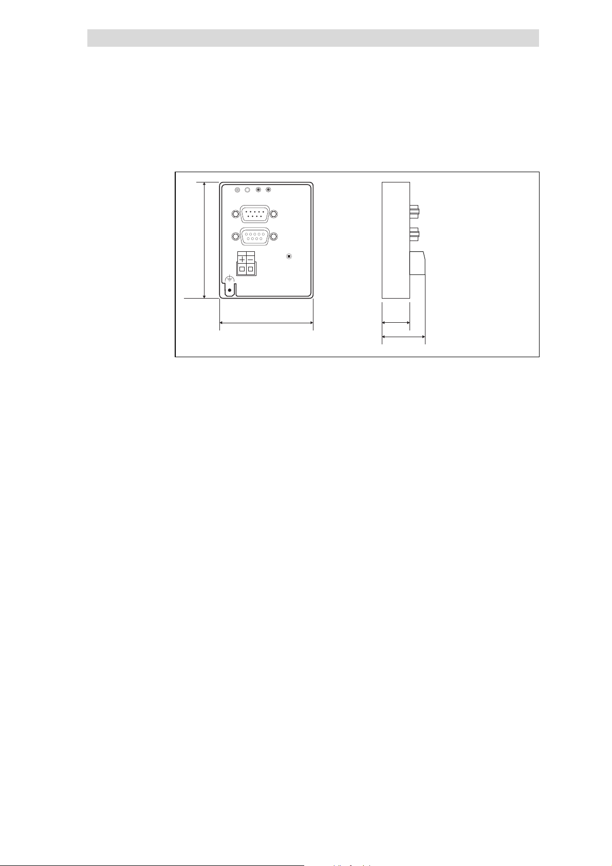
5.3.5 Dimensions
DRIVE
BUS
b
24V DC
+
a61mm
b75mm
e28mm
e1 18 mm
L
INTERBUS S
IN
OUT
_
2111
a
18
Technical data
Dimensions
e1
e
2111IBU005
5.3-4
EDSIBS-1.0-06/ 2003
L
Page 9
2111 INTERBUS fieldbus module
0
1
Show/Hide Bookmarks
5
Installation
Components of the fieldbus module
5.4 Installation
5.4.1 Components of the fieldbus module
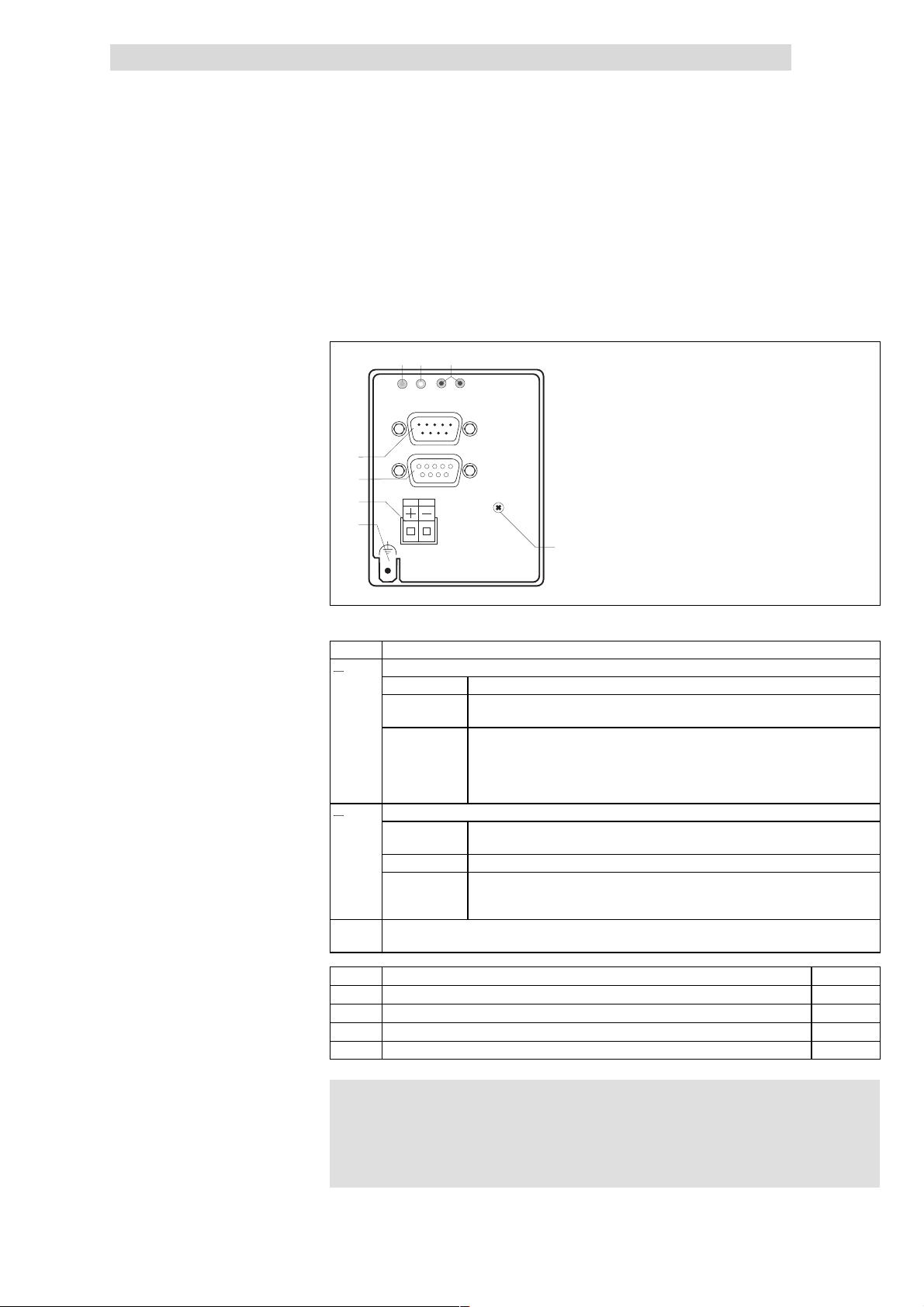
2
1
0
DRIVE
BUS
L
INTERBUS S
IN
3
4
5
24V DC
+
_
OUT
6
Fig. 5.4-1 Components of the fieldb us module
5.4
5.4.1
7
2111
2111IBU004
Pos LED statu s Explanation 3
0
1
2
3
4
5
6
7
Green bus LED (voltage supply)
ON The fieldbus module is supplied with voltage and is connected to the drive controller.
OFF The fieldbus module is not supplied with voltage. The drive controller or external
voltage supply is switched off.
BLINKING The fieldbus module is supplied with voltage, but it is not connected to the drive
controller, because
• the fieldbus module was not plugged on the drive controller correctly
• the data transfer of/to the drive controller is not possible (e. g. the drive controller
is in the initialisation phase).
Yellow bus LED (communication)
ON Fieldbus module is initialised,
inactive INTERBUS communication of the master
OFF Fieldbus module is not initialised yet
BLINKING Active INTERBUS communication
• SLOW (1 Hz): process data and PCP communication.
• FAST (4 Hz): only process data
Red and green drive LED indicate the operating mode of the drive controller 82XX or 93XX (see the
Operating Instructions of the drive controller)
INTERBUS input (IN), Sub-D plug connector, 9-pole
INTERBUS output (OUT), Sub-D socket connector, 9-pole
Plug connector, connection for external voltage supply
PE connection
Fixing screw
^ 5.4-6
^ 5.4-7
^ 5.4-5
see note
L
)
) Note!
))
Only for 820X and 821X: If required use an additional PE screen
cable which avoids EMC-related communication interference in
surroundings with interferences.
EDSIBS-1.0-06/ 2003
5.4-1
Page 10
5
Show/Hide Bookmarks
2111 INTERBUS fieldbus module
5.4
5.4.2
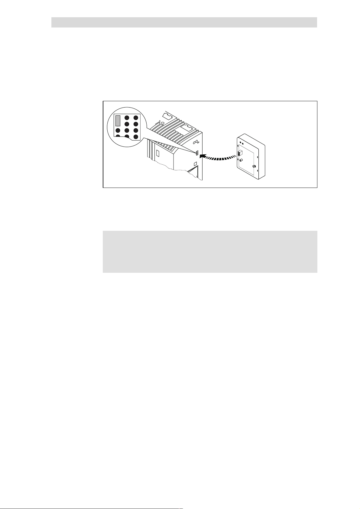
5.4.2 Mechanical installation
l Plug the fieldbus module onto the basic device (here: 8200 vector).
l Fasten the fieldbus module with the fixing screw onto the basic device to
ensure a good PE connection.
Installation
Mechanical installation
4 2102LEC014
)
) Note!
))
For the internal supply of the fieldbus module through the 8200
vector frequency inverter the interface of the jumper must be
adapted (see illustration above). Please observe the notes
^ 5.4-5.
5.4-2
EDSIBS-1.0-06/ 2003
L
Page 11

2111 INTERBUS fieldbus module
Show/Hide Bookmarks
5
Installation
Electrical installation
5.4.3 Electrical installation
Wiring to the INTERBUS master
)
) Note!
))
l The bus system must be designed as a ring.
l Go-and-return lines are both in the same bus cable.
l The ring connec ts the INTERBUS master with all devices connected to the
bus.
5.4
5.4.3
An additional mains isolation is required, if
l a 820X or 821X is connected to an INTERBUS master and
l a safe mains isolation (double basic insulation) is required
according to VDE 0160.
Use e.g. a bus terminal or an interface module for the INTERBUS
master with an additional mains isolation (see the corresponding
information of the manufacturer).
L
EDSIBS-1.0-06/ 2003
5.4-3
Page 12
5
Show/Hide Bookmarks
2111 INTERBUS fieldbus module
5.4
5.4.3
Wiring example
Installation
Electrical installation
1
3.2
400 m
2
Fig. 5.4-2 Wiring examp le, INTERBUS (baud rate 500 kb it/ s)
Pos. Element Explanation
1 INTERBUS master with
interface module
2 INTERBUS loop bus
terminal
3 Remote bus
Fig. 5.4-2 Pos. 3
3.1 Long distance bus module Bus participant in the long distance bus; e.g. Lenze controller with INTERBUS
3.2 Remote bus cable Connects the INTERBUS master interface module with the bus terminal and/or
4 INTERBUS loop, peripheral
bus
Fig. 5.4-2 Pos. 4
4.1 INTERBUS loop module Bus participant in the INTERBUS loop; e.g. Lenze controller with INTERBUS loop
4.2 INTERBUS loop cable Connection within the loop
Features:
Communication medium RS485
Network topology Ring
Maximum number of controllers 62
4.2
3.2
INTERBUS-Loop 100 m
3.1
8200 vector
+
2111
4.1
82XX
+
2112
3.1
400 m
93XX
+
2112
4.2 4.24.2
10 m
93XX
2111
3.1
3.23.2
82XX
+
2111
4.14.1
8200 vector
+
2112
3
4
+
The bus system is a master-slave system, i.e. an INTERBUS master is connected
to several field devices (slaves).
The bus terminal connects a long distance bus to a peripheral bus.
The following connections are possible with remote buses:
• the INTERBUS master interface module and first bus terminal or first 2111
fieldbus module.
• the bus terminal and the 2111 fieldbus module
• two 2111 fieldbus modules
module (slave). Networking does not require bus terminals.
the long distance bus modules.
Connection in a peripheral-bus station
A peripheral-bus station consists of:
• a bus terminal (Fig. 5.4-2 pos. 2)
• up to eight peripheral bus modules (Fig. 5.4-2 pos. 3)
module 2112
2111IBU001
5.4-4
Baud rate / cable length 500 kbit/s / 400 m
Specification of INTERBUS remote bus cable 5
Cable type Yard goods:
IBS RBC Meter-T, order No. 28 06 28 6 (Fa. Phoenix Contact)
Number of conductors 3 x 2, paired with common shielding
Conductor cross-section >0.2mm
2
DC cable resistance <96Ω/km
Impedance, characteristic 120 Ω±20 % (f = 64 kHz)
Ω±15 Ω (f > 1 MHz)
100
Capacitance per unit length < 60 nF/km (f = 800 Hz)
EDSIBS-1.0-06/ 2003
L
Page 13
2111 INTERBUS fieldbus module
Show/Hide Bookmarks
5
Installation
Electrical installation
External DC voltage supply 6
Connection terminals 7
5.4.3
If necessary, supply the 2111 fieldbus module with a separate supply voltage
24 V DC via the two-pole plug connector ±10 %.
Plug connector Name Explanation
+ Vcc24 External supply 24 V DC ± 10 %, 150 mA
- GND24 Reference potential for external voltage supply
Use a separate power supply unit in each control cabinet.
Controller External voltage supply
820X Always required
821X / 822X / 824X and
93XX
8200 vector See information in “internal DC voltage supply”
Electrical connection Plug connector with threaded terminal end
Possible connections
Tightening torque 0.5 ... 0.6 Nm (4.4 ... 5.3 lb-in)
Bare end 6mm
Only necessary if the mains which supply the corresponding controllers is to be switched
off but the communication must not be interrupted.
rigid: 1.5 mm2(AWG 16)
flexible:
without wire crimp cap
2
(AWG 16)
1.5 mm
with wire crimp cap, without plastic sleeve
2
(AWG 16)
1.5 mm
with wire crimp cap, with plastic sleeve
2
(AWG 16)
1.5 mm
5.4
Internal DC voltage supply 8
)
) Note!
))
Basic devices with extended AIF interface opening (8200 vector
front) can be internally supplied. The part of the drawing
highlighted in grey shows the jumper position.
l In the delivery state of the frequency inverter these are not
internally supplied.
l For internal voltage supply, put the jumper in the position
indicated below.
only external voltage supply
Lenze setting
Internal voltage supply
L
EDSIBS-1.0-06/ 2003
5.4-5
Page 14
5
Show/Hide Bookmarks
2111 INTERBUS fieldbus module
5.4
5.4.3
5.4.3.1 Connection from the INTERBUS
Installation
Electrical installation
BUS
DRIVE
L
INTERBUS S
IN
2
4
V
D
C
O
U
+
T
_
2
1
11
2111IBU006
5
9
IN
Sub-D pin connector (IN)
Pin Name Input/output Explanation
1 DO1 Input RS485: DO1 not i nverted
2 DI1 Output RS485: DI1 not inverted
3 GND Reference potential
4 free
5 Vcc5 5VDC
6 /DO1 Input RS485: DO1 inverted
7 /DI1 Output RS485: DI1 inverted
8 Vcc5 5VDC
9 free
Tab. 5.4-1 Pin assignment of the Sub -D pin connector (IN)
1
6
2113IBU012
5.4-6
EDSIBS-1.0-06/ 2003
L
Page 15
2111 INTERBUS fieldbus module
Show/Hide Bookmarks
5
Installation
Electrical installation
5.4.3.2 Connection to the INTERBUS
5.4
5.4.3
B
U
S
D
R
IV
E
L
INTERBUS S
IN
PC
2
4
V
D
C
OUT
+
_
2111
2111IBU006
5
9
OUT
1
6
2113IBU011
Sub-D socket connector (OUT)
Pin Name Input/output Explanation
1 DO2 Output RS485: DO2 not inverted
2 DI2 Input RS485: DI2 not inverted
3
4
GND Reference potential
5 Vcc5 Output 5VDC
6 /DO2 Output RS485: DO2 inverted
7 /DI2 Input RS485: DI2 i nverted
8 Vcc5 5VDC
9 RBST Message input The assignment of the Sub-D socket connector
(OUT) with a Sub-D plug is indicated.
Tab. 5.4-2 Pin assignment of the Sub -D socket c onnector (OUT)
L
EDSIBS-1.0-06/ 2003
5.4-7
Page 16

Show/Hide Bookmarks
Page 17
2111 INTERBUS fieldbus module
Show/Hide Bookmarks
5
Commissioning
Before switching on
5.5.1
5.5 Commissioning
5.5.1 Before switching on
(
( Stop!
((
Before switching on the mains voltage, check the wiring for
completeness, earth fault and short circuit.
)
) Note!
))
Do not change the switch-on sequence!
5.5.2 Configuration of the INTERBUS master for communication with the fieldbus
module
5.5
The program ”SYSSWT”
The host parameters (PC, PLC, etc.) are typically set via the PC program
” SYSSWT” of Phoenix Contact.
)
) Note!
))
mдЙ~лЙ зДлЙкоЙ нЬЙ беСзкг~нбзе ЦбоЙе бе нЬЙ ТpvpptqТ
йкзЦк~гK mкзЦк~г Ду mЬзЙебс `зен~ЕнK
1. Inst all „ SYSSWT“ on the host.
2. Start the program „ SYSSWT” .
3. Select „ Applications“ from the main menu.
4. Then select „ Planning“. A list for field assignment (field names) is displayed.
Please enter the following values:
Field name Entry Explanation
Module/PD
length
Module ID 227 Module identification
CR 2 or higher Communication reference for PCP communication
5. Select the menu „ File“ .
2
2
3
Process-data length in words (16 bit each)
for 82XX
for 93XX Lenze sett i ng (L-C1910 = 4)
for 93XX, when code L-C1910 = 6
L
6. Then select the menu point „ Save planning data“.
– Before saving the new settings, mark the options not to be executed:
( ) NO bus start
( ) NO communication initialization
()NOtransferstop
Mark the options not to be executed.
– Save your settings
7. Close the program „ SYSSWT“.
EDSIBS-1.0-06/ 2003
5.5-1
Page 18
5
Show/Hide Bookmarks
2111 INTERBUS fieldbus module
5.5
5.5.3
Different program
Commissioning
Start up of the 2111 fieldbus module
If you d o not use t he program ” SYSSWT” , the following settings must be mad e:
Name Entry Explanation
Module/PD length
2
2
3
Module ID 227 Module identification
Tab. 5.5-1 Process-data communication
Name Entry Explanation
COM_REF 2 or higher Communication reference (CR)
CONN_TYPE Acyclic
master/slave
CONN_ATTR Defined Connection attribute
Max PDU sending high prio 0 Sending history high priority
Max PDU sending low prio 64 Sending history low priority
Max PDU receiving high prio 0 Receiving history high priority
Max PDU receiving low prio 64 Receiving history low priority
Supported service request 803000
Supported Services Response 000000
Maximum SCC 1
Maximum RCC 0
Maximum SAC 0
Maximum RAC 0
Process-data length in words (16 bit each)
for 82XX
for 93XX Lenze sett i ng (L-C1910 = 4)
for 93XX, when code L-C1910 = 6
Connection type
hex
hex
Supported service, master request
Supported service, slave response
Tab. 5.5-2 PCP communication
5.5.3 Start up of the 2111 fieldbus module
1. The fieldbus module must be attached to the controller (¶ 5.4- 2).
2. Switch on the controller and, if required, the external voltage supply of the
2111 fieldbus module.
3. Check fieldbus module signals:
– The green bus LED indicates the operating status according to the
corresponding description
– The yellow bus LED indicates the communication status according to the
description
– If the signals are different in any way please see the chapter
“Troubleshooting and fault elimination” .
4. You can now communicate with the drive.
– With a PCP communication it is only possible to access the parameters of
the controller after having executed the PCP service ” Initiate“
5. It is then possible to access the parameters via the PCP services ”Read“
and ” Write“
(¶ 5.4-1) Pos. 1.
(¶ 5.6-49).
(¶ 5.4-1) Pos. 0.
(¶ 5.6-49).
5.5-2
EDSIBS-1.0-06/ 2003
L
Page 19
2111 INTERBUS fieldbus module
Show/Hide Bookmarks
5
Commissioning
Prepare controller for INTERBUS oper ation
5.5.4 Prepare controller for INTERBUS operation
82XX / 8200 vector
Preparation Notes
1. L-C0001 (operating mode):
Change value from “0” to “3”
.
2. Terminal 28 (controller
enable) must be HIGH during
INTERBUS operation.
Terminal 28 is always
active!
The controller is now ready to accept process and parameter data from the INTERBUS.
For this use
• the 8201BB for 82XX and
• the keypad for 8200 vector
Alternative
Direct access to the code via INTERBUS.
Example
Set code L-C0001 t o “3” (PCP write):
à For conversion formula and parameter value range see ^ 5.6-46
8200 vector (up to SW version 1.1)
à C0410/y (y = 1...16) must be assigned to the AIF control word (AIF-CTRL)
Otherwise, the controller cannot be enabled by the INTERBUS (DRIVECOM
controller status ”OPERATION ENABLED”, see Operating Instructions for the
controller).
821X, 8200vector und 822X
With these controllers the QSP function is always active. If QSP is assigned to an
input terminal (default setting: not assigned), this terminal must be at HIGH level
during INTERBUS operation (see the corresponding Operating Instructions).
:
– Index: 5FFE
– Subindex: 0
– Value: 30000
i.e. C0410/1 = 10, C0410/2 = 11 .... C0410/16 = 25 (see Operating
Instructions for 8200 vector).
hex
dec
(= 5FFF
− (L-C0001)
hex
hex
5.5
5.5.4
)
93XX controllers
Preparation Notes
1. L-C0005: Set “xxx3”. Use the 9371BB keypad
Alternative:
Direct access to the code via INTERBUS.
For the first commissioning you should select the signal configuration 1013 (speed
control).
Example
Set code L-C0005 to “1013” (PCP write):
– Index: 5FFA
– Subindex: 0
– Value: 10130000
à For conversion formula and parameter value range see ^ 5.6-46
2. L-C0142 (autostart lock):
Set “0”.
3. Terminal 28 (controller
enable) must be HIGH during
INTERBUS operation.
Terminal 28 is always
active!
The controller is now ready to accept process and parameter data from the INTERBUS.
Only necessary with DRIVECOM control
Otherwise, the controller cannot be enabled by the INTERBUS (DRIVECOM
controller status ”OPERATION ENABLED”, see Operating Instructions for 93XX).
à With the signal configuration L-C0005=1013, the function QSP (quick stop) and
the CW/CCW changeover are assigned to the digital input terminals E1 and E2
and thus they are always active. For INTERBUS operation E1 must be set to
HIGH level (see Operating Instructions 93XX).
à With the signal configuration L-C0005=xx13, terminal A1 is switched as
voltage output. Thus, only the following terminals can be connected via cables:
– X5.A1 with X5.28 (ctrl. enable)
– X5.A1 with X5.E1 (CW/QSP)
hex
(5FFF
dec
− (L-C0005)
hex
hex
)
L
EDSIBS-1.0-06/ 2003
5.5-3
Page 20

5
Show/Hide Bookmarks
2111 INTERBUS fieldbus module
5.5
5.5.5
5.5.5 Controller enable via DRIVECOM
Controllers can be controlled with DRIVECOM proc ess data. The INTERBUS
master has direct access to the process data. In the INTERBUS master, data are
stored in the I/O area.
l Controller enable: DRIVECOM process data word ” Control word”
l Display of actual controller status: DRIVECOM process data word ” Status
word”.
The controller can be enabled by changing to OPERATION ENABLED by means
of the DRIVECOM control word.
Afterwards, the controller can be controlled as usual, e.g. via terminals.
)
) Note!
))
If DRIVECOM control is active and the fieldbus module
l in the controller
– 82XX / 8200 vector “ controller inhibit” will be activated if
L-C0001 = 3.
– 93XX “ Controller inhibit” will always be active.
l the fieldbus module sets SWITCH ON INHIBIT.
Commissioning
Controller enable via DRIVECOM
Enable the controller as follows:
1. Select speed setpoint (2nd process data word; PD2), value
2. Change to ” READY FOR SWITCH ON“
PD output word1 = 0000 0000 0111 1110
3. Wait for the status ” READY FOR SWITCH ON“.
PD input word1 = xxxx xxxx x01x 0001
4. Change to ” OPERTION ENABLED“
PD output word1 = 0000 0000 0111 1111
5. Wait for ” OPERATION ENABLED“.
PD input word1 = xxx xxx x01x 0111
bin.
bin.
bin
bin
(007E
(007F
hex
hex
).
).
≠ 0.
5.5-4
EDSIBS-1.0-06/ 2003
L
Page 21

2111 INTERBUS fieldbus module
Show/Hide Bookmarks
5
Commissioning
DRIVECOM compatibility
5.5.6 DRIVECOM compatibility
The DRIVECOM profile 21 is a specification of important parameters and unit
performance of several manufacturers. The DRIVECOM profile 21 mainly
describes the unit control and a speed operating mode. In addition to the
DRIVECOM specifications there are further Lenze-specific functions, e.g.
digital-frequency connection or DCinjection-brake. These manufacturer-specific
specifications require minor changes in the settings to comply with the desired
DRIVECOM compatibility. In the following, you will find the changes required for
the Lenze controllers.
820X With 820X controllers, parameters can only be set when the controller is inhibited.
821X,
8200 vector
and 822X
93XX Set the controller parameters for INTERBUS control, e.g. L-C0005=1013
9300 Servo
PLC
Drive PLC It is necessar y to use the device control for the DRIVE PLC.
5.5
5.5.6
The controller is inhibited in DRIVECOM status.
• ”SWITCH-ON INHIBIT”
• ”READY FOR SWITCH ON”
• ”SWITCHED ON”
• ”TRIP”
The automatic DC-injection brake must be deactivated in all parameter sets, i. e.
• L-C0106=0
• L-C2106=0
• L-C4106=0 (only 8200 vector)
• L-C6106=0 (only 8200 vector)
If the automatic DC-injection brake is not deactivated (holding time o f the DC-injection brake L-C0106
not 0), the controller automatically switches from the status ”OPERATION ENABLED” to the status
”SWITCHED ON” when the speed is 0 and the holding time of the DC-injection brake is elapsed. If the
setpoint is higher than 0, the controller is automatically reset to the status ”OPERATION ENABLED”.
This configuration corresponds to t he signal configuration 1000 with the following changes:
• Setpoint selection with INTERBUS
• Unit control with INTERBUS
• Output X5.A1 is selected as voltage output for the internal supply of the digital inputs.
• Actual values and status signals for INTERBUS
For the detailed description of the signal configuration, see 93XX Manual.
The following links must be made in the PLC program.
• AIF1_wDctrlCtrl W DCTRL_wAIF1Ctrl
• DCTRL_wStat W AIF1_wDctrlStat
L
EDSIBS-1.0-06/ 2003
5.5-5
Page 22

5
Show/Hide Bookmarks
2111 INTERBUS fieldbus module
5.5
5.5.7
Special features when using 82XX, 8200 vector and 93XX
5.5.7 Special features when using 82XX, 8200 vector and 93XX
}
} Danger!
}}
Please note
l For safe operation it is absolutely necessary to observe the
notes for the controllers given in this chapter.
l Please observe the corresponding Operating Instructions of the
controllers.
820X • Parameter setting (codes except process data) is only possible when the controller is inhibited
8200 vector • Digital and analog input and output signals can be freely configured (see Operating Instructions for
93XX • Set the signal configuration L-C0005 = xxx3 instead of the operating mode L-C0001.
(DRIVECOM controller status unequal ”OPERATION ENABLED“). Parameters are accepted when the
controller is enabled, but they are not saved.
• A TRIP must only be reset through INTERBUS:
If the controller is set to the status TRIP while being operated with INTERBUS control
(L-C0001 = 3) and if the TRIP is reset through terminal 28, the drive can start for a short time.
When resetting a fault via INTERBUS, this does not occur.
• Aft er the command ”TRIP reset“ the 820X controller is basically initialized. During this time the
controller does not accept any services.
• Always send the direction of rotation with a low setpoint before the new setpoint:
If the setpoint and the direction of rotation are changed at the same time via the DRIVECOM speed
setpoint, the speed can change to the wrong direction or rotation for a short time. This is because
the setpoint is sent to the controller as unipolar value before and the information about the
direction of rotation is sent.
8200 vector; codes L-C0410, L-C0412, L-C0417 a nd L-C0421)
• A change of code L-C0001 to “3“ preconfigures the process data words in the controller.
• The change o f the code L-C0005 to xxx3 starts the preconfiguration of the process data words in
the controller
• Set the parameter L-C0142 = 0 (auto start lock), to avoid a short time start of the drive during the
initialization phase.
Commissioning
5.5-6
EDSIBS-1.0-06/ 2003
L
Page 23

2111 INTERBUS fieldbus module
Show/Hide Bookmarks
5
Data transfer
5.6 Data transfer
5.6
INTERBUS master and slave communicate by sending data telegrams via the
INTERBUS.
The user data of the data telegram contains parameter data
Different communication channels are assigned to parameter and process data:
Telegram type Communication channel
Process data,
• Setpoints
• Actual values
Parameter data
• Operating parameters
• diagnostics information
• moto r data
Tab. 5.6-1 Division of p arameter data and p rocess d ata into different c ommunication channels
The following describes the communication protocol only as much as needed for
networking Lenze controllers.
Process-data channel • Exchange between INTERBUS master and
Parameter data channel
or “PCP channel”
(PCP = Peripherials
Communication Protocol)
controller required as fast as possible. Small
amounts of data for cyclic data transfer.
• The INTERBUS master has direct access to the
process data.
• Process data can control the controller.
• Process data are
– not stored in the controller.
– exchanged between INTERBUS master and
controllers to ensure a constant update of
input and output data.
• In general, the parameter transfer is not as
time-critical as the tranfer of process data.
• Enables access to all Lenze codes and indexes.
or process data.
L
EDSIBS-1.0-06/ 2003
5.6-1
Page 24

5
Show/Hide Bookmarks
2111 INTERBUS fieldbus module
5.6
5.6.1
5.6.1 Process data channel configuration
5.6.1.1 Process data transfer
Process data telegrams between INTERBUS master and the controllers
connected to the INTERBUS are divided into:
l Process data telegrams from drive (PI)
l Process data telegrams to drive (PO)
)
) Note!
))
As agreed, the data flow is described from the INTERBUS
master’s view:
l PI data of the INTERBUS master are output data for the
controller.
l PO data of the INTERBUS master are input data for the
controller.
Data transfer
Process data channel configuration
Process data telegram from
drive
Process data telegram to
drive
For the cyclic process data telegram from
is called AIF-OUT. The status word included in the process data telegram (byte
1 and byte 2) is sent to the INTERBUS master via this function block.
For the cyclic process data telegram to
is called AIF-IN. The control word included in the process data telegram (byte 1
and byte 2) is sent to the INTERBUS master via this function block.
the drive, the func tion block to be used
the drive, the function block to be used
5.6-2
EDSIBS-1.0-06/ 2003
L
Page 25

2111 INTERBUS fieldbus module
Show/Hide Bookmarks
5
Data transfer
Process data channel configuration
5.6.1.2 Setpoint source selection
82XX controllers
Controller 8200 vector
The setpoint source selection for these controllers is determined under code
L-C0001 (5FFE
is set to ”3” when the controller is operated together with the fieldbus module. The
process data channel which describes the frequency setpoint (L-C0046) and the
control word (parameter channel, L-C0135) is the setpoint source
)
) Note!
))
The setpoint source selection for these controllers is determined under code
L-C0001 (5FFE
is set to ”3” when the controller is operated together with the fieldbus module. The
process data channel which describes the frequency setpoint (L-C0046) and the
control word (parameter channel, L-C0135) is the setpoint source
5.6.1
).An evaluation of process data is only possible if code L-C0001
hex
.
Please ensure that the setpoint source (L-C0001) is the same for
all parameter sets used.
).An evaluation of process data is only possible if code L-C0001
hex
.
5.6
93XX controllers
Servo PLC 9300 / Drive PLC
Check in L-C0412/ x whether the assignment of setpoint source and analog signal
is correct and change, if necessary.
)
) Note!
))
Please ensure that the setpoint source selection (L-C0001) is the
same for all parameter sets used.
The value in code C0005 must be set to ” xxx3” for bus operation (x = selected
preconfiguration).
Communication requires that AIF-IN 1 ... 3 or AIF-OUT 1 ... 3 and if available
AIF management are part of the control configuration of the IEC61131 project.
the
L
EDSIBS-1.0-06/ 2003
5.6-3
Page 26

5
Show/Hide Bookmarks
2111 INTERBUS fieldbus module
5.6
5.6.1
5.6.1.3 Process data configuration
Some data important for the process must be transmitted as quickly as possible.
These data are called process data and stored in the I/O area of the controller for
access from the INTERBUS master.
The process data are cyclically exchanged between the controller and the
INTERBUS master.
Theprocess data of a Process-data configuration have a certain ”Process data
structure“.
The process-data structure is subdivided into
l Process input data (PI data, index = 6000
l Process output data (PO data, index = 6001
The controller receives control information from the INTERBUS master and sends
status information to the master.
The Lenze setting for the process-data length is 4 byte.
The PD length is set under code L-C1910.
Data transfer
Process data channel configuration
, (¶ 5.6-5))
hex
, (¶ 5.6-5))
hex
)
) Note!
))
The assignment of the AIF-CTRL control word to PO data is only
useful, if the Drivecom status machine is switched off. This is
achieved by entering “0” under L-C1911.
Different controller signals can be assigned to the PI and PO data
words (see
(¶ 5.6-6)).
5.6-4
EDSIBS-1.0-06/ 2003
L
Page 27
2111 INTERBUS fieldbus module
M
g
y
Show/Hide Bookmarks
5
Data transfer
Process data channel configuration
PI data description (6000
hex
)9
The parameter describes the process data which are sent from the controller to
the INTERBUS master (input data for the INTERBUS master). Parameters of the
described process data assignment of Lenze controllers can be assigned to the
subindex values (see
changed.
Ensure that the parameters of the process data channel are only used once, i.e.
double assigment must be avoided (example: DC speed and speed setpoint are
sent via AIF-W1).
Parameter name (Index) Subindex Data structure Data type
PI data description (6000
)
) Note!
))
Subindex
1 Number of process data [byte] 04
2 Index PI data word 1 6041
3 Subindex PI data word 1 00
4/5 No entry 00
6 Index PI data word 2 6044
7 Subindex PI data word 2 00
8/9 No entry 00
10 Index PI data word 3 5CA5
11 Subindex PI data word 3 03
12/13 No entry 00
(¶ 5.6-6)). Exception: The value for subindex 1 cannot be
) 1 ... 13 R PBS(20
hex
hex
)
Only the valid subindex is displayed with the parameter 6000
It is determined by PD!
eaning
Value
Lenze setting Notes
hex
DRIVECOM status word
hex
DRIVECOM speed
hex
AIF-OUT.W2
hex
Of if code
L-C1910 = 6
5.6.1
hex
5.6
.
PO data description (6001
hex
)10
The parameter describes the process data which are sent to the controller from
theINTERBUSmaster (output data for the INTERBUS master).Parameters of the
described proc ess data of Lenze controllers can be assigned to subindex values
(¶ 5.6-6)). Exception: The value for subindex 1 cannot be changed.
(see
Ensure that the parameters of the process data channel are only used once, i.e.
double assigment must be avoided (example: DC speed and speed setpoint are
sent via AIF-W1).
Parameter name (Index) Subindex Data structure Data type
PO data description (6001
Subindex Meaning
1 Number of process data
[byte]
2 Index PO data word 1 6040
3 Subindex PO data word 1 00
4/5 No entry 00 1
6 Index PO data word 2 6042
7 Subindex PO data word 2 00
8/9 No entry 00 3
10 Index PO data word 3 5CA7
11 Subindex PO data word 3 03
12/13 No entry 00 5
) 1 ... 13 R PBS(20
hex
Lenze setting
Value
04
hex
DRIVECOM control word 0
hex
DRIVECOM speed setpoint 2
hex
AIF-IN.W2 4
hex
hex
)
hex
index
6002 / Bit
Notes
Only if
L-C1910 = 6
L
EDSIBS-1.0-06/ 2003
5.6-5
Page 28

5
Show/Hide Bookmarks
2111 INTERBUS fieldbus module
5.6
5.6.2
5.6.2 Process data signals of Lenze controllers
5.6.2.1 Process data signals for frequency inverters 82XX
Process data telegram from
drive
ThefollowingparameterscanbeassignedtothePI-data:
Index Subindex Name Explanation Lenze setting:
6041 0 DRIVECOM status word PI data word 1 ^ 5.6-38
6044 0 DRIVECOM speed Actual speed [rpm] PI data word 2 ^ 5.6-41
6054 0 DRIVECOM actual
percentage value
5F69 0 Device status word
(L-C0150)
5CA5 1 AIF-OUT.W1 AIF word 1
Data transfer
Process data signals of Lenze controllers
see
^ 5.6-42
Table below
Actual speed [%]
100% = 16383
Index 6000
hex
5.6-6
EDSIBS-1.0-06/ 2003
L
Page 29

2111 INTERBUS fieldbus module
Show/Hide Bookmarks
5
Data transfer
Process data signals of Lenze controllers
Device status word AIF- STAT for 82XX (Lenze code C0150, index 5F69
Bit 820X 821x, 822x
0 Actual parameter set 0=Parameterset1or3active
1=Parameterset2or4active
1 IMP (pulse inhibit) 0 = Pulses for power stage enabled
1 = Pulses for power stage inhibited
2 I
(current limit reached) 0 = Current limit not reached
max
1 = Current limit reached
3 not assigned fd=f
4 fd=f
5 Qmin (f
dset
≤ f
) 0 = Qmin not active
d
dQmin
6 fd+ 0 (act. frequency = 0) 0=f
0=f
≠ f
d
dset
1=fd=f
dset
1=Qminactive
≠ 0
d
+0
1=f
d
7 Ctrl. inhibit (controller inhibit) 0 = Controller not inhibited
1 = Controller inhibited
8...11 Controller status 0 = Unit initialisation
8 = Error active
12 Overtemperature warning 0=Nowarning
1=Warning
13 V
(DC-bus overvoltage) 0 = No overvoltage
Gmax
1 = Overvoltage
14 Direction of rotation 0 = CW rotation
1 = CCW rotation
15 Ready for operation 0 = Not ready for operation
1 = Ready for operation
)
hex
Actual parameter set 0=Parameterset1or3active
IMP (pulse inhibit) 0 = Pulses for power stage enabled
I
(current limit reached) 0 = Current limit not reached
max
dset
RFG on = RFG off 0=RFGon≠ RFG off
Qmin (f
d
fd+ 0 (act. frequency = 0) 0=f
Ctrl. inhibit (controller inhibit) 0 = Controller not inhibited
Controller status 0 = Controller initialization
Overtemperature warning 0=Nowarning
V
(DC-bus overvoltage) 0 = No overvoltage
Gmax
Direction of rotation 0 = CW rotation
Ready for operation 0 = Not ready for operation
1=Parameterset2or4active
1 = Pulses for power stage inhibited
1 = Current limit reached
0=f
1=fd=f
1 = RFG on = RFG out
≤ f
) 0 = Qmin not active
dQmin
1=Qminactive
1=f
1 = Controller inhibited
2 = Switch on inhibit
3 = Operation inhibited
4 = Flying-restart circuit active
5 = DC brake active
6 = Operation enabled
7 = Message active
8 = Error active
1=Warning
1 = Overvoltage
1 = CCW rotation
1 = Ready for operation
5.6
5.6.2
≠ f
d
dset
dset
≠ 0
d
+0
d
- / fd=fdset
fd=fdset / RFG
ctrl. inhibit
B11 B10 B9 B8
0
0
0
1
0
0
1
0
0
.
.
.
.
.
.
.
.
.
.
.
.
.
.
.
.
.
.
PAR
IMP
Imax
Qmin
fd>0
STAT
0
0
2
0
3
1
.
.
.
.
.
.
Vgmax
RDY
C0050
.
.
.
.
.
.
T
R/L
.B0
.B1
.B2
.B3
.B4
.B5
.B6
.B7
.B8
16 bits
.B9
.B10
.B11
ü
.B12
.B13
.B14
.B15
AIF
16 bits
2141LON012_en
Fig. 5.6-1 Read access to status word and actual frequency in 82XX (fixed assignment)
L
EDSIBS-1.0-06/ 2003
5.6-7
Page 30

5
Show/Hide Bookmarks
2111 INTERBUS fieldbus module
5.6
5.6.2
Process data telegram to drive
Data transfer
Process data signals of Lenze controllers
ThefollowingparameterscanbeassignedtothePO-data:
Index Subindex Name Explanation Lenze setting:
6040 0 DRIVECOM control word PO data word 1 ^ 5.6-35
6042 0 DRIVECOM speed
6052 0 DRIVECOM percentage
5F78 0 Device control word
1 AIF-IN.W1 AIF word 1. See the
5CA7
)
) Note!
))
setpoint
setpoint
(L-C0135)
The assignment of the AIF-CTRL control word to PO data is only
useful, if the Drivecom status machine is switched off. This is
achieved by entering “0” under L-C1911.
Speed setpoint [rpm] PO data word 2 ^ 5.6-41
Speed setpoint [%]
100% = 16383
following description.
Index 6001
hex
see
^ 5.6-42
Table below
5.6-8
EDSIBS-1.0-06/ 2003
L
Page 31

2111 INTERBUS fieldbus module
0
0,0
1
01JOG1activeinC0037
R
d
Show/Hide Bookmarks
5
Data transfer
Process data signals of Lenze controllers
Control w ord AIF- CTRL for 82XX (Lenze code C0135, index 5F78
Bit 820X 821x, 822x
00 = C0046 active
01 = JOG1 active in C0037
10 = JOG2 active in C0038
11 = JOG3 active in C0039
02 CW/CCW (CW rotation/
03 QSP (quick stop) 0 = QSP not active
04 RFG stop (stop of the ramp function generator) 0 = RFG stop not active
05 RFG zero (deceleration along the Tiframp C0013) 0 = RFG zero not active
06
07 DOWN function for motor potentiometer 0 = DOWN not active
08 Reserved
09 Ctrl. inhibit (controller inhibit) 0 = Controller not inhibited
10
11
12 PAR1 (Parameter set changeover) 0 -> 1 = Parameter set
13 Reserved Reserved
14 DC brake (DC injection brake) 0 = DC brake not active
15 Reserved Reserved
CCW rotation)
Reserved
eserve
0 = CW rotation
1 = CCW rotation
1=QSPactive
1 = Controller inhibited
1 -> 0 = Parameter set
1 = DC brake active
)
hex
00 = C0046 active
01 = JOG1 active in C0037
10 = JOG2 active in C0038
11 = JOG3 active in C0039
CW/CCW (CW rotation/CCW rotation) 0 = CW rotation
QSP (quick stop) 0 = QSP not active
UP function for motor potentiometer 0=UPnotactive
Ctrl. inhibit (controller inhibit) 0 = Controller not inhibited
Reserved
TRIP reset 0 -> 1 = Edge from 0 to 1
PAR1 (Parameter set changeover) 0 -> 1 = Parameter set
DC brake (DC injection brake) 0 = DC brake not active
1 = CCW rotation
1=QSPactive
1=RFGstopactive
1=RFGzeroactive
1=UPactive
1 = DOWN active
1 = Controller inhibited
1 -> 0 = Parameter set
1 = DC brake active
5.6
5.6.2
AIF
16 bits
16 bits
.B0
.B1
.B2
.B3
.B4
.B8
.B9
.B10
.B11
.B12
.B13
.B14
.B15
0
011
JOG/
C046
0101
QSP
...
...
...
CINH
TRIP-SET
TRIP-RESET
C0046
Fig. 5.6-2 Access to c ontrol word and actual frequency in 82XX (fixed assignment)
CW/
CCW
PAR
DC
brake
2141LON010_en
L
EDSIBS-1.0-06/ 2003
5.6-9
Page 32

5
C
A
Show/Hide Bookmarks
2111 INTERBUS fieldbus module
5.6
5.6.2
5.6.2.2 Process data signals for 8200 vector frequency inverters
The function block AIF (AIF=automation interface) is the data interface between
the 8200 vector and the fieldbus module. The function block consists of AIF-OUT
and AIF-IN.
Process data telegram from
drive
ThefollowingparameterscanbeassignedtothePI-data:
Index Subindex Name Explanation Lenze setting:
6041 0 DRIVECOM status word PI data word 1 ^ 5.6-38
6044 0 DRIVECOM speed Actual speed [rpm] PI data word 2 ^ 5.6-41
6054 0 DRIVECOM actual
5F69 0 Device status word
1 AIF-OUT.W1 AIF word 1
5
5
2 AIF-OUT.W2 AIF word 2 PI data word 3
AIF-OUT.Wx is parameterised under code L-C0421.
percentage value
(L-C0150)
Process data signals of Lenze controllers
Actual speed [%]
100% = 16383
Index 6000
Data transfer
see
hex
^ 5.6-42
Table below
5.6-10
EDSIBS-1.0-06/ 2003
L
Page 33

2111 INTERBUS fieldbus module
Show/Hide Bookmarks
5
Data transfer
Process data signals of Lenze controllers
Controller status word AIF-STAT for 8200 vector (Lenze code C0150, index 5F69
AIF-STAT.Bxx Lenze setting Adjustable in code L-0417/..
0 DCTRL-PAR-B0 1
1 DCTRL1-IMP 2
2 MCTRL1-IMAX 3
3 MCTRL1-RFG1=NOUT 4
4 NSET1-RFG1-I=0 5
5 PCTRL1-QMIN 6
6 DCTRL1-NOUT=0 7
7 DCTRL1-CINH 8
8...11 Controller status
0 = Controller initialization
2 = Switch on inhibit
3 = Operation inhibited
4 = Flying-restart circuit active
Reserved
5 = DC brake active
6 = Operation enabled
7 = Message active
8 = Error active
12 DCTRL1-OH-WARN 13
13 DCTRL1-OV 14
14 DCTRL1-CCW 15
15 DCTRL1-RDY 16
hex
)
5.6
5.6.2
C0417/1
DCTRL1-IMP
C0417/3
C0417/4
C0417/5
C0417/6
DCTRL1-NOUT=0
DCTRL1-CINH
DCTRL1-STAT*1
DCTRL1-STAT*2
DCTRL1-STAT*4
DCTRL1-STAT*8
DCTRL1-OH-WARN
DCTRL1-OV
C0417/15
C0417/16
C0421/1
C0421/2
STAT1
.B10
.B12
.B13
AIF-OUT.W1
AIF-OUT.W2
.B0
.B1
.B2
.B3
.B4
.B5
.B6
.B7
.B8
.B9
.B11
.B14
.B15
AIF-OUT
.B0
.B1
.B2
.B3
.B4
.B5
.B6
.B7
.B8
AIF-STAT
.B9
16 bits
.B10
.B11
.B12
.B13
.B14
.B15
16 bits
16 bits
Fig. 5.6-3 Function b loc k AIF-OUT in 8200 vector (freely p rogrammable assignment)
AIF
2141LON013_en
L
EDSIBS-1.0-06/ 2003
5.6-11
Page 34

5
C
A
Show/Hide Bookmarks
2111 INTERBUS fieldbus module
5.6
5.6.2
Process data telegram to drive
Data transfer
Process data signals of Lenze controllers
ThefollowingparameterscanbeassignedtothePO-data:
Index Subindex Name Explanation Lenze setting:
6040 0 DRIVECOM control word PO data word 1 ^ 5.6-35
6042 0 DRIVECOM speed
6052 0 DRIVECOM percentage
5F78 0 Device control word
1 AIF-IN.W1 AIF word 1
5
7
2 AIF-IN.W2 AIF word 2
AIF-IN.Wx is parameterised under code L-C0412.
setpoint
setpoint
(L-C0135)
Speed setpoint [rpm] PO data word 2 ^ 5.6-41
Speed setpoint [%]
100% = 16383
Frequency and speed
are normalised with
24000 ≡ 480 Hz.
Frequency and speed
are normalised with
24000 ≡ 480 Hz.
Index 60001
PO data word 3
hex
see
^ 5.6-42
Table below
)
) Note!
))
The assignment of the AIF-CTRL control word to PO data is only
useful, if the Drivecom status machine is switched off. This is
achieved by entering “0” under L-C1911.
5.6-12
EDSIBS-1.0-06/ 2003
L
Page 35

2111 INTERBUS fieldbus module
00,
01NSET1JOG1(C0037)activ
e
1
Show/Hide Bookmarks
5
Data transfer
Process data signals of Lenze controllers
Control w ord AIF- CTRL for 8200 vector (Lenze code C0135, index 5F78
AIF-CTRL.Bxx Default setting:
00,
01
02 DCTRL1-CW/CCW 0=notactive
03 AIF-CTRL-QSP 0=notactive
04 NSET1-RFG1-STOP 0=notactive
05 NSET1-RFG1-0 0=notactive
06 MPOT1-UP 0=notactive
07 MPOT1-DOWN 0=notactive
08 Freely configurable by user 9
09 AIF-CTRL-CINH 0=notactive
10 AIF-CTRL-TRIP-SET 0=notactive
11 AIF-CTRL-TRIP-RESET 0 -> 1 = Edge from 0 to 1 AIF-CTRL-TRIP-RESET 0 -> 1 = Edge from 0 to 1 12
12 DCTRL1-PAR2/4 0=notactive
13 DCTRL1-PAR3/4 0=notactive
14 MCTRL1-DCB 0=notactive
15 Freely configurable by user Freely configurable by user 16
00 = C0046 active
01 = NSET1-JOG1 (C0037) a ct ive
10 = NSET1-JOG2 (C0038) a ct ive
11 = NSET1-JOG3 (C0039) a ct ive
C0001=3 if C0007
≤ 51
1=active
1=active
1=active
1=active
1=active
1=active
1=active
1=active
1=active
1=active
1=active
)
hex
Default setting:
C0001=3 if C0007 > 51
Freely configurable by user
AIF-CTRL-QSP 0=notactive
Freely configurable by user
AIF-CTRL-CINH 0=notactive
AIF-CTRL-TRIP-SET 0=notactive
Freely configurable by user
1=active
1=active
1=active
5.6
5.6.2
Adjustable in L-C0410/..
1
2
3
4
5
6
7
8
10
11
13
14
15
AIF
AIF-CTRL
16 bits
16 bits
16 bits
.B0
.B1
.B2
.B3
.B4
.B8
.B9
.B10
.B11
.B12
.B15
AIF-IN
DCTRL
QSP
...
...
...
...
...
...
Fig. 5.6-4 Function b lock AIF-IN in 8200 vector (freely programmable assignment)
...
...
...
DCTRL
CINH
TRIP-SET
TRIP-RESET
...
...
...
AIF-IN.W1
AIF-IN.W2
2141LON011_en
L
EDSIBS-1.0-06/ 2003
5.6-13
Page 36

5
Show/Hide Bookmarks
2111 INTERBUS fieldbus module
5.6
5.6.2
5.6.2.3 Process data signals for servo inverters 9300
The function block AIF (AIF = automation interface) is the data interface between
the 93XX controller and the fieldbus module. The function block consists of
AIF-OUT and AIF-IN.
With the 93XX controller the process data assignment can be changed by
reconfiguring the function blocks AIF-IN and AIF-OUT.
Data transfer
Process data signals of Lenze controllers
5.6-14
EDSIBS-1.0-06/ 2003
L
Page 37

2111 INTERBUS fieldbus module
Show/Hide Bookmarks
5
Data transfer
Process data signals of Lenze controllers
Process data telegram from
drive
ThefollowingparameterscanbeassignedtothePI-data:
Index Subindex Name (same in
6041 0 DRIVECOM status word PI data word 1 ^ 5.6-38
6044 0 DRIVECOM speed Actual speed [rpm] PI data word 2 ^ 5.6-41
6054 0 DRIVECOM actual
5F69 0 Device status word
5CA5 1 AIF1-OUT.W1 AIF word 1
5CA5 2 AIF1-OUT.W2 AIF word 2 PI data word 3
5CA5 3 AIF1-OUT.W3 AIF word 3
5CA4 0 AIF1-OUT.D1 AIFdoubleword
The assignment of AIF-OUT depends on the signal configuration selected under
L-C0005:
Signal
configuration
(L-C0005)
Speed control
1003
1013
1113
Torque control
4003
4013
4113
DF master
5003
5013
5113
DF-slave bus
6003
6013
6113
DF-slave cascade
7003
7013
7113
Not equal to xxx3
(except self
configurations)
IEC1131)
percentage value
(AIF1_Stat)
AIF-OUT.W1 AIF-OUT.W2 AIF-OUT.W3 AIF-
MCTRL-NACT
Actual speed
100%=16383
MCTRL-MSET2
Torque display
100%=16383
MCTRL-NACT
Actual speed
100%=16383
MCTRL-NACT
Actual speed
100%=16383
MCTRL-NACT
Actual speed
100%=16383
MCTRL-NACT
Actual speed
100%=16383
Explanation Lenze setting:
Actual speed [%] ^ 5.6-42
MCTRL-MSET2
Torque display
100%=16383
MCTRL-NACT
Act. speed in %
100%=16383
MCTRL-MSET2
Torque display
100%=16383
MCTRL-PHI-ACT
Actual phase
MCTRL-PHI-ACT
Actual phase
MCTRL-MSET2
Torque display
100%=16383
Index 6000
hex
MCTRL-NSET2
Speed controller input
100%=16383
MCTRL-NSET2
Speed controller input
100%=16383
MCTRL-NSET2
Speed controller input
100%=16383
MCTRL-MSET2
Torque setpoint in %
100%=16383
MCTRL-MSET2
Torque setpoint in %
100%=16383
MCTRL-PHI-ACT
Actual phase
see
Table below
OUT.D1
not
assigned
not
assigned
not
assigned
not
assigned
not
assigned
not
assigned
5.6
5.6.2
L
For detailed description of the 93XX signal configuration see the Operating
Instructions for 93XX (only the main configurations: 1000, 4000, 5000, etc.) or the
Manual 93XX.
In the c ontroller, other signals can be assigned to AIF-OUT.W1 to AIF-OUT.W3.
For this, thefunction-block configuration - described in the Manual 93XX- is used.
The function block AIF-OUT determines the output data of the controller as data
interfac e for the 2133 fieldbus module.
For more detailed information about the function block AIF-OUT, see the Manual
93XX.
EDSIBS-1.0-06/ 2003
5.6-15
Page 38

5
8...1
1
Show/Hide Bookmarks
2111 INTERBUS fieldbus module
5.6
5.6.2
Process data signals of Lenze controllers
Data transfer
Controller status word AIF-STAT for 93XX
9300 Servo 9300 POS 9300 CRV 9300 Vector
L-C0005:
1xxx, 2xxx,
Bit..
1xx3 4xx3 5xx3 6xx3,7xx3 2xxx3 xxx3
3xxx, 5xxx,
4xx3 6xx3,7xx3
10xxx, 11xxx
0 DCTRL-PAR1-0 DCTRL-PAR1-0 DCTRL-PAR1-0 DCTRL-PAR1-0 not assigned CERR1-ERR DCTRL-PAR1-0 DCTRL-PAR1-0 DCTRL-PAR1-0
1 DCTRL-IMP DCTRL-IMP DCTRL-IMP DCTRL-IMP DCTRL-IMP DCTRL-IMP DCTRL-IMP DCTRL-IMP DCTRL-IMP
2 MCTRL-IMAX MCTRL-IMAX REF-OK REF-OK POS-REF-OK MCTRL-IMAX MCTRL-IMAX MCTRL-IMAX MCTRL-IMAX
3 MCTRL-MMAX not assigned MCTRL-MMAX not assigned not assigned MCTRL-MMAX MCTRL-MMAX MCTRL-IMAX
MCTRL-MMAX
negated
4 NSET-RFG-I=0 MCTRL-IMAX
negated
NSET-RFG-I=0 MCTRL-IMAX
negated
MCTRL-MMAX
negated
DCTRL-TRIP NSET-RFG-I=0 NSET-RFG-I=0 NSET-QSP-OUT
5 QMIN QMIN REF-BUSY REF-BUSY POS-IN-TARGET CDATA-X0 QMIN QMIN QMIN
6 DCTRL-
NACT=0
DCTRLNACT=0
DCTRLNACT=0
DCTRLNACT=0
DCTRLNACT=0
DCTRLNACT=0
DCTRLNACT=0
DCTRLNACT=0
DCTRL-
NACT=0
7 DCTRL-CINH DCTRL-CINH DCTRL-CINH DCTRL-CINH DCTRL-CINH DCTRL-CINH DCTRL-CINH DCTRL-CINH DCTRL-CINH
8 ... 11
Controller status:
0=
Unit initialisation
2=
Switch-on inhibit
3=
Operation inhibited
4=
Flying-restart circuit active
5=
DC-injection brake active
6=
Operation enabled
7=
Message active
8=
Fault active
10 =
Fail-QSP (only 9300 servo positioning controller)
12 DCTRL-WARN DCTRL-WARN DCTRL-WARN DCTRL-WARN DCTRL-WARN DCTRL-WARN DCTRL-WARN DCTRL-WARN DCTRL-WARN
13 DCTRL-MESS DCTRL-MESS DCTRL-MESS DCTRL-MESS DCTRL-MESS DCTRL-MESS DCTRL-MESS DCTRL-MESS DCTRL-MESS
14 DCTRL-CW/
CCW
DCTRL-CW/
CCW
DCTRL-CW/
CCW
not assigned DCTRL-AIFL-
QSP
DCTRL-CW/
CCW
DCTRL-CW/
CCW
DCTRL-CW/
CCW
DCTRL-CW/
CCW
15 DCTRL-RDY DCTRL-RDY DCTRL-RDY DCTRL-RDY DCTRL-RDY DCTRL-RDY DCTRL-RDY DCTRL-RDY DCTRL-RDY
C 0 1 5 6 / 1
C 0 1 5 6 / 6
C 0 1 5 6 / 7
C 1 1 9 5
C 0 8 5 0 / 1
C 0 8 5 0 / 2
C 0 8 5 0 / 3
C 0 1 1 6 / 1
C 0 1 1 6 / 1 6
C 0 1 1 6 / 1 7
C 0 1 1 6 / 3 2
C 0 8 5 1
S T A T
S T A T . B 0
D C T R L - I M P
. . .
S T A T . B 1 4
S T A T . B 1 5
A I F - O U T . D 2
C 1 1 9 6
A I F - O U T . W 1
C 0 8 5 8 / 1
C 0 8 5 8 / 2
C 0 8 5 8 / 3
F D O - 0
. . .
F D O - 1 5
F D O - 1 6
. . .
F D O - 3 1
A I F - O U T . D 1
C 0 8 5 9
F D O
1 6 b i t s
1 6 b i t s
L o w W o r d
1 6 b i t s
H ig h W o r d
A I F - O U T . W 2
A I F - O U T . W 3
1 6 b i t s
L o w W o r d
1 6 b i t s
H ig h W o r d
1 6 b i t s
L o w W o r d
1 6 b i t s
H ig h W o r d
A I F - O U T
B i t 0
S t a t u s w o r d
B i t 1 5
B i t 0
C 0 8 5 4
0
3
C 0 8 5 2
0
1
2
3
C 0 8 5 3
0
1
2
B i t 1 5
B i t 0
B i t 3 1
B y t e 3 , 4
:
B y t e 5 , 6
B y t e 7 , 8
2113IBU009_en
Fig. 5.6-5 Function b loc k AIF-OUT (function block extension on grey b ackground: available as
of software version 2.0 on)
5.6-16
EDSIBS-1.0-06/ 2003
L
Page 39

2111 INTERBUS fieldbus module
notassignednotassigne
d
Show/Hide Bookmarks
5
Data transfer
Process data signals of Lenze controllers
Process data telegram to drive
ThefollowingparameterscanbeassignedtothePO-data:
Index Subindex Name Explanation Lenze setting:
6040 0 DRIVECOM control word PO data word 1 ^ 5.6-35
6042 0 DRIVECOM speed
6052 0 DRIVECOM percentage
5F78 0 Device control word
5CA7 1 AIF-IN.W1 AIF word 1
5CA7 2 AIF-IN.W2 AIF word 2 PO data word 3
5CA7 3 AIF-IN.W3 AIF word 3
5CA6 0 AIF-IN.D1 AIFdoubleword
)
) Note!
))
5.6.2
see
^ 5.6-42
Table below
setpoint
setpoint
(AIF1_CTRL)
Index 6001
Speed setpoint [rpm] PO data word 2 ^ 5.6-41
Speed setpoint [%]
100% = 16383
hex
The assignment of the AIF-CTRL control word to PO data is only
useful, if the Drivecom status machine is switched off. This is
achieved by entering “0” under L-C1911.
5.6
The assignment of AIF-IN.W1 to AIF-IN.W3 depends on the signal configuration
selected under L- C0005:
Signal configuration
(L-C0005)
Speed control
1003 / 1013 / 1113
Torque control
4003 / 4013 / 4113
DF master
5003 / 5013 / 5113
DF-slave bus
6003 / 6013 / 6113
DF-slave cascade
7003 / 7013 / 7113
not equal to xxx3 not assigned not assigned
AIF-IN.W1 AIF-IN.W2 AIF-IN.W3 AIF-IN.D1
NSET-N
Speed setpoint
MCTRL-MADD
Torque setpoint
NSET-N
Speed setpoint
DFSET-A-TRIM
Phase trimming
DFSET-VP-DIV
DF factor
not assigned
not assigned
not assigned
not assigned not assigned
DFSET-N-TRIM
Speed trimming
DFSET-A-TRIM
Phase trimming
For detailed description of the 93XX signal configuration see the Operating
Instructions for 93XX (only the main configurations: 1000, 4000, 5000, etc.) or the
Manual 93XX.
In the controller, other signals can be assigned to AIF-IN.W1 to AIF-IN.W3. For
this, the function-block configuration - described in the Manual 93XX - is used.
The function block AIF-IN determines the input data of the controller as data
interfac e for the 2133 fieldbus module.
For more detailed information about the function block AIF-IN, see the Manual
93XX.
L
EDSIBS-1.0-06/ 2003
5.6-17
Page 40

5
X
. . .. . .
Show/Hide Bookmarks
2111 INTERBUS fieldbus module
5.6
5.6.2
Process data signals of Lenze controllers
Data transfer
Control word AIF- CTRL for 93XX
9300 Servo 9300 POS 9300 CRV 9300 Vector
L-C0005:
1xxx, 2xxx,
Bit
1xx3 4xx3 5xx3 6xx3,7xx3 2xxx3 xxx3
3xxx, 5xxx,
4xx3 6xx3,7xx3
10xxx, 11xxx
0 NSET-JOG*1 not assigned NSET-JOG*1 not assigned not assigned CSEL1-CAM*1 NSET-JOG*1 not assigned not assigned
1 NSET-JOG*2 not assigned NSET-JOG*2 not assigned not assigned CSEL1-CAM*2 NSET-JOG*2 not assigned not assigned
2 NSET-N-INV NSET-N-INV NSET-N-INV NSET-N-INV not assigned CSEL1-CAM*4 NSET-N-INV not assigned not assigned
3 AIF-CTRL.QSP AIF-CTRL.QSP AIF-CTRL.QSP AIF-CTRL.QSP AIF-CTRL.QSP AIF-CTRL.QSP AIF-CTRL.QSP AIF-CTRL.QSP AIF-CTRL.QSP
4 NSET-RFG-STOP NSET-RFG-
STOP
NSET-RFGSTOP
NSET-RFGSTOP
POS-PRG-START CSEL1-EVENT NSET-RFG-
STOP
NSET-RFGSTOP
not assigned
5 NSET-RFG-0 NSET-RFG-0 NSET-RFG-0 NSET-RFG-0 POS-PRG-STOP CDATA-CYCLE NSET-RFG-0 NSET-RFG-0 not assigned
6 not assigned not assigned not assigned not assigned not assigned CSEL1-LOAD not assigned not assigned not assigned
7 not assigned not assigned not assigned not assigned POS-PRG-RESET CSEL1-LOAD not assigned not assigned not assigned
8 not assigned not assigned not assigned not assigned not assigned not assigned not assigned not assigned not assigned
9 AIF-CTRL.CINH AIF-CTRL.CINH AIF-CTRL.CINH AIF-CTRL.CINH AIF-CTRL.CINH AIF-CTRL.CINH AIF-CTRL.CINH AIF-CTRL.CINH AIF-CTRL.CINH
10 AIF-CTRL.TRIP-SET AIF-CTRL.TRIP-
SET
11 AIF-CTRL.TRIP-
RESET
AIF-CTRL.TRIPRESET
AIF-CTRL.TRIPSET
AIF-CTRL.TRIPRESET
AIF-CTRL.TRIPSET
AIF-CTRL.TRIPRESET
AIF-CTRL.TRIPSET
AIF-CTRL.TRIPRESET
AIF-CTRL.TRIPSET
AIF-CTRL.TRIPRESET
AIF-CTRL.TRIPSET
AIF-CTRL.TRIPRESET
AIF-CTRL.TRIPSET
AIF-CTRL.TRIPRESET
AIF-CTRL.TRIPSET
AIF-CTRL.TRIP-
RESET
12 DCTRL-PAR*1 DCTRL-PAR*1 DCTRL-PAR*1 DCTRL-PAR*1 POS-PS-CANCEL not assigned DCTRL-PAR*1 DCTRL-PAR*1 DCTRL-PAR*1
13 DCTLR-PAR-LOAD DCTLR-PAR-
LOAD
DCTLR-PARLOAD
DCTLR-PARLOAD
POS-PARAM-RD not assigned DCTLR-PAR-
LOAD
DCTLR-PARLOAD
DCTLR-PAR-
LOAD
14 NSET-Ti*1 NSET-JOG*1 REF-ON REF-ON POS-LOOP-ONH not assigned NSET-Ti*1 NSET-JOG*1 not assigned
15 NSET-Ti*2 NSET-JOG*2 NSET-Ti*1 not assigned POS-STBY-STP not assigned NSET-Ti*2 NSET-JOG*2 not assigned
A I F - I N
C 0 8 5 6 / 1
C 1 1 9 7
D C T R L
Q S P
D I S A B L E
C I N H
T R I P - S E T
T R I P - R E S E T
A I F - C T R L . B 0
A I F - C T R L . B 1
A I F - C T R L . B 2
A I F - C T R L . B 4
A I F - C T R L . B 5
A I F - C T R L . B 6
A I F - C T R L . B 7
A I F - C T R L . B 1 2
A I F - C T R L . B 1 3
A I F - C T R L . B 1 4
A I F - C T R L . B 1 5
A I F - I N . W 1
A I F - I N . D 2
A I F - I N . W 2
A I F - I N . W 3
A I F - I N . B 0
A I F - I N . B 2
A I F - I N . B 1 4
A I F - I N . B 1 5
A I F - I N . B 1 6
A I F - I N . B 1 7
A I F - I N . B 3 0
A I F - I N . B 3 1
A I F - I N . D 1
A I F - C T R L . B 3
A I F - C T R L . B 8
A I F - C T R L . B 9
A I F - C T R L . B 1 0
1 6 b i t s
C 0 1 3 6 / 3
1 6 b i t s
1 6 b i t s
1 6 b i t s
C 0 8 5 5 / 1
1 6
b i n a r y
s i g n a l s
C 0 8 5 5 / 2
1 6
b i n a r y
s i g n a l s
1 6 b i t s
L o w W o r d
1 6 b i t s
H i g h W o r d
A I F - C T R L . B 1 1
1 6 b i t s
L o w W o r d
1 6 b i t s
H i g h W o r d
C 0 8 5 6 / 2
C 0 8 5 6 / 3
C 0 8 5 7
B i t 0
C o n t r o l w o r r d
B i t 1 5
B y t e 3 , 4B y t e 5 , 6
1
B y t e 7 , 8
5.6-18
2113IBU008_en
Fig. 5.6-6 Function b loc k AIF-IN (grey: Extension available as of software version 2.0)
EDSIBS-1.0-06/ 2003
L
Page 41

2111 INTERBUS fieldbus module
Show/Hide Bookmarks
5
Data transfer
Process data signals of Lenze controllers
5.6.2.4 Process data signals for 9300 servo PLC and Drive PLC
Process data telegram from
drive
The following data can be assigned to the PE data:
Index Subindex Name/variable name Explanation Lenze setting: Ind ex 6000
6041 0 DRIVECOM status word PI data word 1
6044 0 DRIVECOM speed Actual speed [rpm] PI data word 2
6054 0 DRIVECOM actual percentage
value
5F69 0 Device status word
(AIF1_DctrlStat)
5CA5 1 AIF_nOutW1_a AIF word 1
5CA5 2 AIF_nOutW2_a AIF word 2 PI data word 3
5CA5 3 AIF_nOutW3_a AIF word 3
5CA5 4 AIF2_nOutW1_a AIF word 4
5CA5 5 AIF2_nOutW2_a AIF word 5
5CA5 6 AIF2_nOutW3_a AIF word 6
5CA5 7 AIF2_nOutW4_a AIF word 7
5CA5 8 AIF3_nOutW1_a AIF word 8
5CA5 9 AIF3_nOutW2_a AIF word 9
5CA5 10 AIF3_nOutW3_a AIF word 10
5CA5 11 AIF3_nOutW4_a AIF word 11
5CA4 0 AIF1_dnOutD1_p AIFdoubleword1
5.6
5.6.2
hex
Actual speed [%]
)
) Note!
))
9300 Servo PLC
Please execute the following logic operations in the PLC program
of the controller:
AIF1_wDctrlCtrl W DCTRL_wAIF1Ctrl
DCTRL_wStat W AIF1_wDctrlStat
Drive PLC
It is necessary to use the device control for the Drive PLC.
L
EDSIBS-1.0-06/ 2003
5.6-19
Page 42

5
Show/Hide Bookmarks
2111 INTERBUS fieldbus module
5.6
5.6.2
AIF1_wDctrlStat
AIF1_nOutW1_a
AIF1_nOutW2__a
AIF1_bFDO0_b
AIF1_bFDO15_b
AIF1_nOutW3_a
AIF1_bFDO16_b
AIF1_bFDO31_b
…
…
AIF1_dnOutD1_p
C0858/1
C0858/2
C0858/3
C0859
16 bits
16 bits
16 bits
C0151/4
16 binary
signals
16 bits
C0151/4
16 binary
signals
16 bits
Low Word
16 bits
High Word
Outputs_AIF1
Byte
Byte
Byte
Byte
Byte
Byte
Byte
Byte
Data transfer
Process data signals of Lenze controllers
AIF2_nOutW1_a
1
2
3
4
5
6
7
8
Automation
Interface
AIF2_bFDO0_b
...
AIF2_bFDO15_b
AIF2_nOutW2_a
AIF2_bFDO16_b
...
AIF2_bFDO31_b
AIF2_dnOutD1_p
AIF2_nOutW3_a
AIF2_nOutW4_a
16 bits
16 binary
signals
16 bits
16 binary
signals
16 bits
Low Word
16 bits
High Word
16 bits
16 bits
Outputs_AIF2
Byte
Byte
Byte
Byte
Byte
Byte
Byte
Byte
1
2
3
4
5
6
7
8
Automation
Interface
AIF3_nOutW1_a
AIF3_bFDO0_b
...
AIF3_bFDO15_b
AIF3_nOutW2_a
AIF3_bFDO16_b
...
AIF3_bFDO31_b
AIF3_dnOutD1_p
AIF3_nOutW3_a
AIF3_nOutW4_a
Fig. 5.6-7 Function b locks AIF-OUT1, AIF-OUT2 and AIF-OUT3
16 bits
16 binary
signals
16 bits
16 binary
signals
16 bits
Low Word
16 bits
High Word
16 bits
16 bits
Outputs_AIF3
Byte
Byte
Byte
Byte
Byte
Byte
Byte
Byte
1
2
3
4
5
6
7
8
Automation
Interface
5.6-20
EDSIBS-1.0-06/ 2003
L
Page 43

2111 INTERBUS fieldbus module
Show/Hide Bookmarks
5
Data transfer
Process data signals of Lenze controllers
Process data telegram to drive
The following data can be assigned to the PA data:
Index Subindex Name/variable name Explan ation Lenze setting: Index 6001
6040 0 DRIVECOM control word PO data word 1
6042 0 DRIVECOM speed setpoint Speed setpoint [rpm] PO data word 2
6052 0 DRIVECOM percentage setpoint Speed setpoint [%]
5F78 0 Device control word (AIF1_wDctrlCtrl)
5CA7 1 AIF1_nInW1_a AIF word 1
5CA7 2 AIF1_nInW2_a AIF word 2 PO data word 3
5CA7 3 AIF1_nInW3_a AIF word 3
5CA7 4 AIF2_nInW1_a AIF word 4
5CA7 5 AIF2_nInW2_a AIF word 5
5CA7 6 AIF2_nInW3_a AIF word 6
5CA7 7 AIF2_nInW4_a AIF word 7
5CA7 8 AIF3_nInW1_a AIF word 8
5CA7 9 AIF3_nInW2_a AIF word 9
5CA7 10 AIF3_nInW3_a AIF word 10
5CA7 11 AIF3_nInW4_a AIF word 11
5CA6 0 AIF1_dnInD1_p AIFdoubleword1
5.6
5.6.2
hex
)
) Note!
))
9300 Servo PLC
Please execute the following logic operations in the PLC program
of the controller:
AIF1_wDctrlCtrl W DCTRL_wAIF1Ctrl
DCTRL_wStat W AIF1_wDctrlStat
Drive PLC
It is necessary to use the device control for the Drive PLC.
L
EDSIBS-1.0-06/ 2003
5.6-21
Page 44

5
Show/Hide Bookmarks
2111 INTERBUS fieldbus module
5.6
5.6.2
Automation
Interface
Inputs_AIF1
Byte
1
Controlword
Byte
2
Byte
3
Byte
4
Byte
5
Byte
6
Byte
7
Byte
8
16 bits
16 binary
signals
16 bits
16 bits
C0855/1
16 binary
signals
16 bits
C0855/2
16 binary
signals
16 bits
Low Word
16 bits
High Word
C0856/1
C0856/2
C0856/3
C0857
AIF1_wDctrlCtrl
AIF1_bCtrlB0_b
AIF1_bCtrlB1_b
AIF1_bCtrlB2_b
AIF1_bCtrlQuickstop_b
AIF1_bCtrlB4_b
AIF1_bCtrlB5_b
AIF1_bCtrlB6_b
AIF1_bCtrlB7_b
AIF1_bCtrlDisable_b
AIF1_bCtrlCInhibit_b
AIF1_bCtrlTripSet_b
AIF1_bCtrlTripReset_b
AIF1_bCtrlB12_b
AIF1_bCtrlB13_b
AIF1_bCtrlB14_b
AIF1_bCtrlB15_b
AIF1_nInW1_a
AIF1_nInW2_a
AIF1_bInB0_b
…
AIF1_bInB15_b
AIF1_nInW3_a
AIF1_bIn16_b
…
AIF1_bIn31_b
AIF1_dnInD1_p
Data transfer
Process data signals of Lenze controllers
Inputs_AIF2
16 bits
16 binary
signals
16 bits
16 binary
signals
16 bits
Low Word
16 bits
High Word
16 bits
16 bits
16 bits
16 binary
signals
16 bits
16 binary
signals
16 bits
Low Word
16 bits
High Word
16 bits
16 bits
Automation
Interface
Automation
Interface
Byte
1
Byte
2
Byte
3
Byte
4
Byte
5
Byte
6
Byte
7
Byte
8
Inputs_AIF3
Byte
1
Byte
2
Byte
3
Byte
4
Byte
5
Byte
6
Byte
7
Byte
8
AIF2_nInW1_a
AIF2_bInB0_b
...
AIF2_bInB15_b
AIF2_nInW2_a
AIF2_bInB16_b
...
AIF2_bInB31_b
AIF2_dnInD1_p
AIF2_nInW3_a
AIF2_nInW4_a
AIF3_nInW1_a
AIF3_bInB0_b
...
AIF3_bInB15_b
AIF3_nInW2_a
AIF3_bInB16_b
...
AIF3_bInB31_b
AIF3_dnInD1_p
AIF3_nInW3_a
AIF3_nInW4_a
5.6-22
Fig. 5.6-8 Function b locks AIF-IN1, AIF-IN2 and AIF-IN3
EDSIBS-1.0-06/ 2003
L
Page 45

2111 INTERBUS fieldbus module
Show/Hide Bookmarks
5
Data transfer
Process data preconfiguration depending on L-C0009
5.6.3 Process data preconfiguration depending on L-C0009
Use L-C0009 to assign predefined values to the process data words (see table
below).
This preconfiguration is meant to help you with applications whic h do not require
aPCP.
Presettings for the process data configuration can be made under code L-C0009
using the Drive PLC or any controller (82XX, 8200 vector, 93XX) even if the
INTERBUS is not connected.
It is also possible to configure the fieldbus module through the parameter channel
via index 6000
and 6001
hex
The process data configuration resulting from L-C0009 is automatically
l stored in the process data description structure when the device is
switched on.
WIndex 6000
l immediately active.
hex
(¶ 5.6-5)
.
hex
/ Index 6001
hex
(¶ 5.6-5)
5.6
5.6.3
.
l automatically writes the process data length (PD) in L-C1910 and
DRIVECOM in L-C1911 from the table. A change of the PD length will only
become active after mains switching.
The default setting of L- C0009 is “1” and influences the process data
configuration.
L-C0009 PD length (L-C1910) DRIVECOM (L-C1911) PD word 1 PD word 2 PD word 3
11 2 0 GSTW AIF-W1 12 2 0 AIF-W1 AIF-W2 13 2 0 AIF-W2 AIF-W3 14 2 1 DCSTW* DCG 15 2 1 DCSTW* DCG % 16 2 1 DCSTW* AIF-W1 17 2 0 GSTW DCG 18 2 0 GSTW DCG % 21 3 1 DCSTW* DCG AIF-W2
22 3 1 DCSTW* DCG % AIF-W2
23 3 1 DCSTW* AIF-W1 AIF-W2
24 3 1 DCSTW* AIF-W2 AIF-W3
25 3 0 GSTW AIF-W1 AIF-W2
26 3 0 GSTW AIF-W2 AIF-W3
27 3 0 AIF-W1 AIF-W2 AIF-W3
*
GSTW:
AIF-Wx:
DCSTW:
DCG
DCG %:
^ 5.6-29
Device control word/device status word
AIF-IN/OUT.Wx
DRIVECOM control word/DRIVECOM status word
DRIVECOM speed [rpm]
DRIVECOM speed [%]
L
EDSIBS-1.0-06/ 2003
5.6-23
Page 46

5
2.Set
L-C0009=14(
d
)
Show/Hide Bookmarks
2111 INTERBUS fieldbus module
5.6
5.6.3
Examples for process data
preconfiguration
Data transfer
Process data preconfiguration depending on L-C0009
Example 1: DRIVECOM control with 2 process data words (e.g. configuration L -C0009 = 14)
Settings/measures 1. Remove the fieldbus module and disconnect it from the voltage
Result • The indexes 6000
Acceptance of settings The fieldbus module must be switched on again to activate the process
Example 2: Device control with 2 process data words (e.g. configuration L-C0009 = 25)
Settings/measures 1. Remove the fieldbus module and disconnect it from the voltage
Result • The indexes 6000
Acceptance of settings The fieldbus module must be switched on again to activate the process
supply
3. Attach the fieldbus module again and connect it to the voltage
supply
and DCG.
• The process data length (PD) is set to 2 words by L-C1910 = 4.
• DRIVECOM is activated with L-C1911 = 1.
data word length.
supply
2. Set L-C0009 = 25 (e.g. via keypad)
3. Attach the fieldbus module again and connect it to the voltage
supply
AIF-W1, AIF-W2.
• The process data length (PD) is set to 3 words by L-C1910 = 6.
• DRIVECOM is activated by L-C1911 = 0.
data word length.
e.g. viakeypa
and 6001
hex
and 6001
hex
accept the configurations DCSTW
hex
accept the configurations GSTW,
hex
5.6-24
EDSIBS-1.0-06/ 2003
L
Page 47

2111 INTERBUS fieldbus module
Show/Hide Bookmarks
5
Data transfer
Examples for the configuration of PI/PO data
5.6.4 Examples for the configuration of PI/PO data
PI data configuration
The PI data word 2 is to be assigned to the actual percentage (index = 6054
Procedure:
1. Data type derived from the code table ^ 5.6-42.
– The data type of the parameter actual percentage value is I16, i.e. it is a word parameter (16 bit). The code
table for the parameter ”Process input data description structure“ (index = 6000
word 2 is to be entered under subindex 6 and 7 (word parameters).
– The subindex of the paramet e r ”PI data description“ (index = 6000
”Write“ (see
2. Enter the index of the parameter ”Actual percentage“: Write (index = 6000
3. Enter the subindex of the parameter ”Actual percentage“: Write (index = 6000
)
) Note!
))
^ 5.6-49).
The index must be changed to zero to change a subindex.
You can then change the subindex before the index.
) shows that the PI data
hex
) can be written with the PCP service
hex
, subindex = 6
hex
subindex = 7
hex
, value = 6054
hex
,value=0
hex
5.6
5.6.4
hex
hex
)
hex
).
)
L
EDSIBS-1.0-06/ 2003
5.6-25
Page 48

5
Show/Hide Bookmarks
2111 INTERBUS fieldbus module
5.6
5.6.4
PO data configuration
Data transfer
Examples for the configuration of PI/PO data
ThePO data word 2is to be assigned to the percentage setpoint (index =6052
Procedure:
1. Data type derived from the code table ^ 5.6-42.
à The data type of the parameter ”Percentage setpoint“ is I16, i.e. it is a word parameter (16 bit). The code table
for the paramet er ”Process output data description structure“ (index = 6001
to be entered under subindex 6 and 7 (word parameters).
The subindex of the parameter ”PO data description“ (index = 6001
”Write“.
)
) Note!
))
The description of PO data results in inconsistent data, as the
data are exchanged between controller and INTERBUS master in
very short cycle times.
Therefore, the PO data are automatically inhibited when changing
the PO data configuration. After the adaptation of the PO data to
the new configuration, the data can be enabled via the parameter
”PO data enable” (index 6002
hex
hex
).
) shows that the PO data word 2 is
hex
) can be described with the PCP service
hex
).
2. Enter the index of the parameter ”Percentage setpoint“: Write
(index = 6001
3. Enter the subindex of the parameter ”Percentage setpoint“: Write
(index = 6001
)
) Note!
))
4. Enter the i ndex of the parameter ”PO data enable“ (6002
Write (index = 6002
Now the PO data can be read again from the controller.
)
) Note!
))
, subindex = 6
hex
, subindex = 7
hex
The index must be changed to zero to change a subindex.
You can then change the subindex before the index.
, subindex = 0
hex
If a parameter is configured for PO data (e.g. the parameter
”Control word“ (6040
write this parameter directly via its index (example: index =
6040
hex
)
, value = 6054
hex
,value=0
hex
,value=FF
hex
)
hex
)
hex
) to enable process data :
hex
)
hex
) in Lenze setting), it is not possible to
hex
5.6-26
EDSIBS-1.0-06/ 2003
L
Page 49

2111 INTERBUS fieldbus module
Show/Hide Bookmarks
5
Data transfer
Device control
5.6.5 Device control
5.6
5.6.5
)
) Note!
))
Deactivate the DRIVECOM control if you want to use the device
control (AIF-CTRL).
Use code L-C1911.
If you use the device control AIF-CTRL, the control information is determined by
the control inputs (terminal)
Explanation: Fig. 5.6-9
l Status word:
The controller status word AIF-STAT contains information about the current
controller status.
l Commands
– in the DRIVECOM parameter ”Control word“ are switched off and cannot
change the controller status.
– for changing the controller status are to be entered through the
corresponding control input.
(¶ 5.6-3).
Switch on unit
NOT READY TO SWITCH ON
pí~íìë ïçêÇ ññññ ññññ ñMññ MMMM
~мнзг~нбЕ~дду пЬЙе
нЬЙ бебнб~дбл~нбзе бл
ЕзгйдЙнЙЗ
READY TO SWITCH ON
pí~íìë ïçêÇ ññññ ññññ ñMNñ MMMN
~ìíçã~íáÅ~ääó
SWITCHED ON
pí~íìë ïçêÇ ññññ ññññ ñMNñ MMNN
`íêäK Éå~ÄäÉGG `нкдK беЬбДбнGG
OPERATION EN AB LED
pí~íìë ïçêÇ ññññ ññññ ñMNñ MNNN
npmGG
Fig. 5.6-9 Status d iagram for d evice control AIF-CTRL
qofm EÑ~ìäíF
pí~íìë ïçêÇ ññññ ññññ ñMññ NMMM
Fault
qofm кЙлЙнGG
kзнЙW
qЬЙ нЙкгл г~квЙЗ пбнЬ GG ~кЙ Езгг~еЗл
L
EDSIBS-1.0-06/ 2003
5.6-27
Page 50

5
Show/Hide Bookmarks
2111 INTERBUS fieldbus module
5.6
5.6.5
Data transfer
Device control
Status Meaning
NOT READY TO SWITCH ON The controller is still in the initialisation phase and not ready for operation.
It then automatically switches to the status READY TO SWITCH ON.
READY TO SWITCH ON The controller is inhibited and waits for the power stage to be charged. It then
automatically switches to the status ”SWITCHED ON“.
SWITCHED ON The controller is inhibited and waits for controller enable.
OPERATION ENABLED The controller is enabled. In this status, a pulse inhibit can be set automatically.
FAULT The controller is in the status ”FAULT“ (TRIP).
5.6-28
EDSIBS-1.0-06/ 2003
L
Page 51

2111 INTERBUS fieldbus module
Show/Hide Bookmarks
5
Data transfer
DRIVECOM control
5.6.6 DRIVECOM control
With INTERBUS control (for 82XX/8200vector: Lenze parameter L-C0001 = 3; for
93XX: always) and when using the fieldbus module, Lenze controllers have a
controller status according to the DRIVECOM profile 21.
Explanation: Fig. 5.6-10
l The DRIVECOM parameter “ Status word” contains information about the
l Commands in the DRIVECOM parameter ”Control word“ can change the
current controller status. Marked by rectangles.
controller status. Marked by arrows.
bс~гйдЙW
pн~нмл беСзкг~нбзе об~ й~к~гЙнЙк Тлн~нмл пзкЗТ
EбеЗЙс SMQN
Switch on unit
F Äáí NR KKK Äáí M EÄáå~êóF
ÜÉñ
FAULTREACTION ACTIVE
pí~íìë ï çêÇ ññññ ññññ ñMññ NNNN
13
c~мдн п ~л
кЙЕзЦеблЙЗ
~мнзг~нбЕ~дду пЬЙе
кЙ~Енбзе нз Йккзк бл зоЙк
5.6
5.6.6
NOT READY TOSWITCH ON
pí~íìë ï çêÇ ññññ ññññ ñMññ MMMM
~ìíçã~íáÅ~ääó ïÜÉå
нЬЙ бебнб~дбл~нбзе бл
ЕзгйдЙнЙЗ
SWITCH ON INHIBIT
pí~íìë ï çêÇ ññññ ññññ ñMññ MMMM
9
fеЬбДбн о здн~ЦЙ
сссс сссс сссс ссMс
pí~íìë ï çêÇ ññññ ññññ ñMNñ MMMN
8
pн~еЗлнбдд
сссс сссс сссс
сNNM
pí~íìë ï çêÇ ññññ ññññ ñMNñ MMNN
bе~ДдЙ зйЙк~нбзе
сссс сссс сссс NNNN ~еЗ
~ЕнK лйЙЙЗ о~дмЙ Y[ M G
pí~íìë ï çêÇ ññññ ññññ ñMNñ MNNN
fеЬбДбн ocd б л г~ййЙЗ нз имбЕв лнзй
2
READY TO SWITC H ON
3
pпбнЕЬ зе
сссс сссс сссс
сNNN
SWITCHED ON
45
OPER ATI ON EN ABL ED
pн~еЗлнбдд
сссс сссс сссс
сNNM
Faul t
pí~íìë ï çêÇ ññññ ññññ ñMññ NMMM
14
oÉëÉí Ñ~ìäí
ññññ ññññ Mñññ ññññ
ññññ ññññ Nñññ ññññ
10
fеЬбДбн оздн~ЦЙ
сссс сссс сссс ссMс
nìáÅâ ëíçé
ññññ ññññ ññññ ñMNñ
7
6
pн~еЗлнбдд
сссс сссс сссс сNNM
lйЙк~нбзе беЬбДбн
сссс сссс сссс MNNN зк ~ЕнK
лйЙЙЗ о~дмЙ Z MG
QUICK STOP ACTIVE
pí~íìë ï çêÇ ññññ ññññ ñMNñ MNNN
11
nìáÅâ ëíçé
ññññ ññññ ññññ ñMNñ
kзнЙW
G зеду ЙССЙЕнбоЙ Сзк UONuI UOMM оЙЕнзк оЙЕнзк пЬЙе нЬЙ ~мнзг~нбЕ
a`JбеаЙЕнбзе Дк~вЙ бл ~ЕнбоЙ EiJ`MNMSI iJ`ONMS Y[ MF
12
fеЬбДбн о здн~ЦЙ
сссс сссс сссс ссMN
çê
имбЕв лнзй Езгйд ЙнЙЗ
L
Fig. 5.6-10 Status diagram: DRIVECOM control
EDSIBS-1.0-06/ 2003
5.6-29
Page 52

5
Show/Hide Bookmarks
2111 INTERBUS fieldbus module
5.6
5.6.6
Explanation of the status
diagram for DRIVECOM control
Data transfer
DRIVECOM control
Status Meaning
NOT READY TO SWITCH ON The controller is being initialised and is not yet ready to operate. It then
SWITCH ON INHIBIT The controller is inhibited and waits for command 2 (shut down).
READY TO SWITCH ON The controller is inhibited and waits for command 3 (switch on).
SWITCHED ON The controller is inhibited and waits for command 4 (enable operation).
OPERATION ENABLED The controller is enabled. In this status, a pulse inhibit can be set
FAULT REACTION ACTIVE A fault (TRIP) was recognised and a fault response initiated.
FAULT The controller is in the status ”FAULT“ (TRIP).
QUICK STOP ACTIVE While being in the status ”OPERATION ENABLED“ the command ”quick stop“
)
) Note!
))
automatically switches to the status READY TO SWITCH ON.
automatically.
was set. The controller is decelerated in a controlled way (quick-stop ramp).
After deceleration, the controller automatically changes to the controller
status ”SWITCH ON INHIBIT“.
The actual unit status can only be clarified by combining the
unit-status information bits (bit 0 to 6). This is shown in the
following:
Controller status Bits of the status word
Bit 6 5 4 3 2 1 0
NOT READY TO SWITCH ON 0 0 0 0 0
SWITCH ON INHIBIT 1 0 0 0 0
READY TO SWITCH ON 0 1 0 0 0 1
SWITCHED ON 0 1 0 0 1 1
OPERATION ENABLED 0 1 0 1 1 1
FAULT 0 1 0 0 0
FAULT REACTION ACTIVE 0 1 1 1 1
QUICK STOP ACTIVE 0 0 0 1 1 1
Switch-on inhibit
Quick stop
Voltage inhibit
Fault
Operation enabled
Switched on
Ready to switch on
0 = Bit status is 0
1 = Bit status is 1
no entry = Any bit status, no influence
5.6-30
EDSIBS-1.0-06/ 2003
L
Page 53

2111 INTERBUS fieldbus module
Show/Hide Bookmarks
5
Data transfer
DRIVECOM control
Explanation of the commands in
the status diagram for
DRIVECOM control
Command Meaning
COMMAND 2, 6, 8 (standstill)
Control word: bit 0 = 0
COMMAND 3 (switch on) Command to change to the controller status ”SWITCHED ON“.
COMMAND 4 (enable operation) Command to change to the controller status ”OPERATION ENABLED“.
COMMAND 5 (inhibit operation) Command to change to the controller status ”SWITCHED ON“.
COMMAND 7, 9, 10, 12 (voltage
inhibit)
Control word: bit 1 = 0
COMMAND 7, 10, 11 (quick stop)
Control word: bit 2 = 0
COMMAND 13 (malfunction/TRIP)) The controller has recognised a malfunction. For some malfunction a
COMMAND 14 (reset fault/TRIP)
Control word: bit 7 = 0
⇒ 1
Command to change from different states to the status ”READY TO SWITCH
ON“.
The controller inhibit is deactivated.
The controller inhibit is activated.
Command to change to the controller status ”SWITCH ON INHIBIT“.
The controller inhibit is activated.
Command to change to the controller status ”SWITCH ON INHIBIT“.
If the controller was enabled, it is decelerated in a controlled way along the
Lenze quick-stop ramp.
controlled deceleration may be necessary (depending on the controller).
Once completed, the controller changes to the status FAULT.
With t he series 821X, 8200 vector this command acknowledges a n error.
The controller changes to the status ”SWITCH ON INHIBIT“ when a fault is no
longer recognised.
5.6
5.6.6
)
) Note!
))
The single bit-control commands depend on other bit positions.
In the following you will find a description of the bits required to
effect the command.
Controller status commands Bits of the control word
Bit 7 6 5 4 3 2 1 0
1 Standstill 1 1 0
2Switchon 1 1 1
3 Operation enable 1 1 1 1
4 Operation inhibit 0 1 1 1
5 Voltage inhibit 0
6Quickstop 0 1
8Errorreset 0®1
Error reset
RFG-zero
RFG-stop
RFG inhibit
Operation enable
Quick stop
Voltage inhibit
Switch on
L
0 = Bit status is 0
1 = Bit status is 1
no entry = Any bit status, no influence
EDSIBS-1.0-06/ 2003
5.6-31
Page 54

5
Show/Hide Bookmarks
2111 INTERBUS fieldbus module
5.6
5.6.7
5.6.7 DRIVECOM profile parameters
5.6.7.1 Process data description
PI data description (6000
PO data description (6001
PO data enable (6002
hex
)
hex
hex
)
)
The description is on page
The description is on page
The parameter enables or inhibits the PO data (output data for INTERBUS
master). By this, the consistency of the PO data is guaranteed.
Inhibit output data: 00
Enable output data: FF
Every bit enables a process data byte!
If you change 6001
automatically. That means, that the controller does not receive new control data
until index 6002
Parameter name (Index) Subindex Data structure Data type
Enable PO data (6002
All process data are enabled when the device is switched on (6002
hex
) 0 S OS
hex
Data transfer
DRIVECOM profile parameters
(¶ 5.6-5).
(¶ 5.6-5).
hex
hex
, the changed process data bytes will be inhibited
hex
enables the communication again.
hex
≡ FF
hex
)
5.6-32
EDSIBS-1.0-06/ 2003
L
Page 55

2111 INTERBUS fieldbus module
Show/Hide Bookmarks
5
Data transfer
DRIVECOM profile parameters
5.6.7.2 Monitoring parameters
Process data monitoring time
(6003
Process data monitoring
selection code (6004
hex
)
)
hex
If the transmission of the process data is inactive for longer than the set monitoring
time (PCD watchdog), the action set in the parameter ” process-data monitoring
selection code” (6004
Parameter name (Index) Subindex Data structure Data type Value range
Process data monitoring time
(6003
The parameter determines the reaction of the controller after the process data
monitoring time is over (6003
Parameter name (Index) Subindex Data structure Data type Value range
Process data monitoring selection
code (6004
hex
5.6
5.6.7
) will be activated.
hex
)
)
hex
0 S OS-1
).
hex
0 S I16 0 (Lenze setting),
OS: Octet
string,
length: 4
0 - 65535
(Lenze setting: 65535,
monitoring is switched off)
0 = No action
2:
Unit control command
„Inhibit voltage“ (controller
inhibit with latching in the
status ”SWITCH ON INHIBIT“)
3:
Unit control command
”Quick stop“ (quick stop
(QSP)withlatchinginthe
status ”SWITCH ON
INHIBIT“).
L
EDSIBS-1.0-06/ 2003
5.6-33
Page 56

5
Show/Hide Bookmarks
2111 INTERBUS fieldbus module
5.6
5.6.7
5.6.7.3 Error code (603F
Data transfer
DRIVECOM profile parameters
)
hex
If the drive sets TRIP, the error code transmits an error number which corresponds
to the DRIVECOM profile (see chapter 5.7.4 DRIVECOM error code).
A list of errors which occurred in Lenze controllers is stored under the Lenze
parameters:
l 82XX: L-C0162 - L-C0164
l 93XX: L-C0168 with subindex 1 to 8
Parameter name (Index) Subindex Data structure Data type
Error code (603F
) 0 S U16
hex
OS
5.6-34
EDSIBS-1.0-06/ 2003
L
Page 57

2111 INTERBUS fieldbus module
Show/Hide Bookmarks
5
Data transfer
DRIVECOM profile parameters
5.6.7.4 DRIVECOM control word (6040
The controller is controlled via this parameter. It contains comands for the
transition between different controller states (see chapter 5.6.6) and other
important control commands (see the following table).
Parameter name (Index) Subindex Data structure Data type
Control word (6040
)
) Note!
))
5.6.7
)
hex
) 0 S OS
hex
The bits contained in the control word are interdependent control
commands which are to be parameterised. Chapter 5.6.6
describes the bits required to make the the command become
effective.
5.6
L
EDSIBS-1.0-06/ 2003
5.6-35
Page 58

5
5FREE
RFGstop
6FREE
DRIVECO
M
Manufacture
r
Manufacture
r
DRIVECO
M
Show/Hide Bookmarks
2111 INTERBUS fieldbus module
5.6
5.6.7
Struct ure of t he DRIVECOM
control word
DRIVECOM profile parameters
Bit Name Meaning
0 Switch on Controller status 0 = command 2, 6, 8 (controller inhibit)
1 Voltage inhibit Controller status 0 = command 9, 10, 12 (controller inhibit)
2 Quick stop Controller status 0 = Command 7, 10, 11 (quick stop)
3 Operation
enable
4 RFG inhibit Inhibit of the
5 FREE
DRIVECOM:
RFG-stop
6 FREE
DRIVECOM:
RFG-zero
7 Error reset Fault reset (TRIP). For this, a bit change from 0 to 1 is required.
8-10 Reserve DRIVECOM reserved
11 FREE
Manufacturer
12 FREE
DRIVECOM:
Manufacturer
13 FREE
DRIVECOM:
Manufacturer
14 FREE
Manufacturer
15 FREE
DRIVECOM:
Manufacturer
Controller status 0 = Command 5 (controller inhibit)
ramp-funtion
generator.
820X: Not assigned
821X, 822X: Output of the RFG (speed setpoint integrator) is ”frozen”.
8200 vector, 93XX: Free. Mapping to bit AIF-CTRL.B4 negated.
820X: Not assigned
821X, 822X: Ramp function generator input (speed setpoint integrator) = 0
8200 vector, 93XX: Free. Mapping to bit AIF-CTRL.B5 negated.
For 82XX, the controller is initialised. During this time, the controller does not accept any
commands.
820X, 821X, 822X: Not assigned
:
8200 vector, 93XX: Free. Mapping to bit AIF-CTRL.B7.
820X, 821X, 822X: Parameter set changeover:
8200 vector, 93XX: Free. Mapping to bit AIF-CTRL.B12.
820X, 821X, 822X: DC-injection brake:
8200 vector, 93XX: Free. Mapping to bit AIF-CTRL.B13.
820X, 821X, 822X: Not assigned
:
8200 vector, 93XX: Free. Mapping to bit AIF-CTRL.B14.
8201X PE inhibit
821X, 822X: Not assigned
8200 vector, 93XX: Free. Mapping to bit AIF-CTRL.B15.
1 = command 3 (controller inhibit)
1 = command ”voltage inhibit“ not active
1 = Command ”quick stop“ not active
1 = Command 4 (controller inhibit not active)
Quick stop is activated without the controller leaving its status.
0 = RFG inhibit (quick stop)
1 = RFG inhibit not active
0=RFGstop
1 = RFG stop not active
(controlled deceleration along the set ramp)
0=RFGzero
1 = RFG zero not active
® 1=Parameterset2
0
1
® 0=Parameterset1
0 = DCB not active
1=DCBactive
Inhibit the update of the PO data of the controller (input data for
the master).
Updates of status and current information of the process channel
can be inhibited in order to send control information more
precisely in time (see chapter 5.3.4.2).
0 = Read status and actual value
1 = Do not read status and actual value
Data transfer
5.6-36
EDSIBS-1.0-06/ 2003
L
Page 59

2111 INTERBUS fieldbus module
Show/Hide Bookmarks
5
Data transfer
DRIVECOM profile parameters
Link between DRIVECOM control
word and AIF- CTRL control for
93XX and 9300 Servo PLC
Steuerwort
INTERBUS-Master
B0
B1
B2
B3
B4
B5
B6
B7
B8
B9
B10
B11
B12
B13
B14
B15
DRIVECOM State
Machine
1
1
C0136/3
AIF-CTRL.B3
AIF-CTRL.B8
AIF-CTRL.B9
AIF-CTRL.B10
AIF-CTRL.B11
AIF-IN
DCTRL
QSP
DISABLE
CINH
TRIP-SET
TRIP-RESET
AIF-CTRL.B0
AIF-CTRL.B1
AIF-CTRL.B2
AIF-CTRL.B4
AIF-CTRL.B5
AIF-CTRL.B6
AIF-CTRL.B7
AIF-CTRL.B12
AIF-CTRL.B13
AIF-CTRL.B14
AIF-CTRL.B15
5.6
5.6.7
2113IBU006
L
EDSIBS-1.0-06/ 2003
5.6-37
Page 60

5
Show/Hide Bookmarks
2111 INTERBUS fieldbus module
5.6
5.6.7
5.6.7.5 DRIVECOM status word (6041
This parameter provides compact information about the controller. It contains
commands for the transition between the different controller states (see chapter
5.6.6) and other important information (see the following table).
)
) Note!
))
Parameter name (Index) Subindex Data structure Data type
Status word (6041
Data transfer
DRIVECOM profile parameters
)
hex
The current controller status can only be clarified by combining
the bits with the status information (bit 0, 1, 2, 3, 4, 5 and 6). This
isshowninchapter5.6.6.
) 0 S OS
hex
5.6-38
EDSIBS-1.0-06/ 2003
L
Page 61

2111 INTERBUS fieldbus module
Show/Hide Bookmarks
5
Data transfer
DRIVECOM profile parameters
Struct ure of t he DRIVECOM
status word
5.6
5.6.7
Bit Name Meaning
0 Ready to switchonController status information
1 Switched on Controller status information
2 Operation
enabled
3 Fault Controller status information
4 Voltage inhibited Information about the command ”voltage inhibit“ (see chapter 5.6.7.4 ”control word“)
5 Quick stop Information about the command ”quick stop“ (see chapter 5.6.7.4 ”control word“)
6 Switch-on
inhibit
7 Warning Collective warning
8 Meldung Collective message. Automatic setting and resetting of pulse inhibit in the controller status
9 Remote 82XX, 821X, 822X,
10 FREE
DRIVECOM:
Setpoint
reached
11 Limit value Status of the DRIVECOM speed limitation
12 FREE
DRIVECOM:
Reserve
13 FREE
DRIVECOM:
Reserve
14 Manufacturer 820X, 821X, 822X:
15 Manufacturer 820X, 821X, 822X:
0 = Status lower than ”READY TO SWITCH ON“
1 = Status at least ”READY TO SWITCH ON“
0 = Status lower than ”SWITCHED ON“
1 = Status at least ”SWITCHED ON“
Controller status information
0 = Status lower than ”OPERATION ENABLED“
1 = Status ”OPERATION ENABLED“
0 = No fault (TRIP))
1 = Fault (TRIP) occured
0 = Command active
1 = Command not active
0 = Command active
1 = Command not active
Controller status information
0 = Statu not ”SWITCH-ON INHIBIT“
1 = Status ”SWITCH-ON INHIBIT“
0=Nowarning
1 = Warning (overtemperature)
”OPERATION ENABLED”. Reasons for this can be under voltage or overvoltage as well as
overcurrent (clamp).
0 = No message
1 = Message (IMP)
8200 vector:
93XX:
Status of speed/frequency deviation
0=RFG
1=RFGon=RFG
0 = Limitation not addressed
1 = Limitation addressed
820X, 821X, 822X:
8200 vector, 93XX:
82XX:
8200 vector:
93XX:
8200 vector, 93XX:
8200 vector, 93XX:
<> RFG
on
Bus access, depends on Lenze parameter ”operating mode”
(L-C0001):
0 = L- C0001
1 = L- C0001
0 = L- C1911 = 0
1 = L- C1911 = 1
off
off
Not assigned
Free. Mapping to bit L-C0150.B14
Not assigned
Free. Mapping to bit L-C0150.B15
Free. Mapping to bit L-C0150.B3
I
max
0 = Current limit not reached
1 = Current limit exceeded
Free. Mapping to bit L-C0150.B2
Q
min(fd
0=Q
1=Q
Free. Mapping to bit L-C0150.B5
<> 3 or L-C1911 = 0
= 3 and L-C1911 = 1
(current limit reached)
≤ f
)
dQmin
not active
min
active
min
L
EDSIBS-1.0-06/ 2003
5.6-39
Page 62

5
Show/Hide Bookmarks
2111 INTERBUS fieldbus module
5.6
5.6.7
Link between DRIVECOM status
word and function block STAT
for 93XX and 9300 Servo PLC
C0156/1
C0156/2
C0156/3
C0156/4
C0156/5
C0156/6
C0156/7
STAT.B0
DCTRL-IMP
STAT.B2
STAT.B3
STAT.B4
STAT.B5
DCTRL-NACT=0
DCTRL-CINH
DCTRL-STAT*1
DCTRL-STAT*2
DCTRL-STAT*4
DCTRL-STAT*8
DCTRL-WARN
DCTRL-MESS
STAT.B14
STAT.B15
STAT
DRIVECOM profile parameters
DRIVECOM State
Machine
Data transfer
Statuswort
INTERBUS-Master
B0
B1
B2
B3
B4
B5
B6
B7
B8
B9
B10
B11
B12
B13
B14
B15
2113IBU007
5.6-40
EDSIBS-1.0-06/ 2003
L
Page 63

2111 INTERBUS fieldbus module
Show/Hide Bookmarks
5
Data transfer
DRIVECOM profile parameters
5.6.7.6 Speed/ velocity channel
Speed setpoint (6042
Speed reference variable
(6043
Actual speed value (6044
hex
)
hex
) 11
hex
) 12
The parameter sets the speed setpoint [rev/min]. If this parameter is changed,
also the nominal percentage will be changed.
Parameter name (Index) Subindex Data structure Data type Value range
Speed setpoint
(6042
This parameter is the output valueof the speed ramp function generator [rev/min].
Parameter name (Index) Subindex Data structure Data type Value range
Speed ref e rence variable (6043
The parameter indicates the actual speed (in rpm).
Parameter name (Index) Subindex Data structure Data type Value range
Actual speed
(6044
hex
hex
5.6
5.6.7
)
)
0 S I16 −32768 to 32767
) 0 S I16 −32768 to 32767
hex
0 S I16 −32768 to 32767
Min/max speed value (6046
Setpoint factor (604B
hex
)
hex
)
This parameter indicates the minimum and the maximum speed (in rpm). It is
initialised with the Lenze parameter L-C0011. Changing this parameter does not
result in a change of L-C0011 (see ”Speed-reference value”).
Parameter name (Index) Subindex Data structure Data type Value range
Min/max speed value (6046
hex
)
1 A U32 0 to 32000
2 A U32 0 to 32000
0: Minimum speed setpoint
[rev/min]
L-C0011: Maximum speed
setpoint [rev/min]
This parameter is used to change the resolution or the setting rangeof the setpoint
input. It consists of numerator and denominator. The setpoint is multiplied by the
setpoint factor; the actual values (reference variable, actual value) are multiplied
by the inverse setpoint factor.
Parameter name (Index) Subindex Data structure Data type Value range
Setpoint factor (604B
hex
)
1 A I16 −32768 to 32767
Lenze setting: 1
(Numerator of the ”Setpoint
factor“)
2 A I16 −32768 to 32767
Lenze setting: 1
(Denominator of the
”Setpoint factor“)
L
EDSIBS-1.0-06/ 2003
5.6-41
Page 64

5
Show/Hide Bookmarks
2111 INTERBUS fieldbus module
5.6
5.6.7
Pole number (604D
Speed reference value (604E
Percentage setpoint (6052
hex
) 13
hex
hex
) 14
Data transfer
DRIVECOM profile parameters
The parameter indicates the pole number of asynchronous motors and is used to
convert frequency values into speed values. Only even values are possible.
Parameter name (Index) Subindex Data structure Data type Value range
Pole number (604D
)
This parameter is the reference value for the relative speed parameters, e.g.
nominal percentage, actual percentage and acceleration time. The parameter is
mapped to the Lenze parameter L-C0011. A conversion to frequency values is
possible. The parameter determines the internal maximum speed, which is also
active with terminal control.
Parameter name (Index) Subindex Data structure Data type Meaning
Speed re f e re nce value (604E
This parameter is the nominal speed in percent. It is scaled to the ” speed
reference value“ (= 100 % ). When changing this parameter, also the ”nominal
speed“ will be changed. If the ” nominal speed“ exceeds the limit value of the
”nominal percentage“ of 200 % during reading, it will be returned as a value
limited to 200 % .
) 0 S U8 2, 4, 6, ..., 254
hex
) 0 S U32
hex
Lenze setting: 4
L-C0011
2
in [rev∕min]
Percentage reference variable
(6053
Actual percentage (6054
hex
)
) 15
hex
Parameter name (Index) Subindex Data structure Data type Value range
Percentage setpoint (6052
) 0 S I16 −32768 to 32767
hex
(100 % = 16383)
This parameter is the ” speed reference variable“ in percent. It is scaled to the
”speed reference value“ (= 100 % ). The ”percentage reference variable“ is
multiplied by the inverse ” setpoint factor“ .
Parameter name (Index) Subindex Data structure Data type Value range
Percentage reference variable
)
(6053
hex
0 S I16 −32768 to 32767
(100 % = 16383)
This parameter is the ”actual speed“ in percent. It is scaled to the ” speed
reference value“ .
Parameter name (Index) Subindex Data structure Data type Value range
Actual percentage (6054
) 0 S I16 −32768 to 32767
hex
(100 % = 16383)
Map of L-C0381
5.6-42
EDSIBS-1.0-06/ 2003
L
Page 65

2111 INTERBUS fieldbus module
Show/Hide Bookmarks
5
Data transfer
DRIVECOM profile parameters
5.6.7.7 Ramps
5.6
5.6.7
The DRIVECOM profile 21 provides two ramps for the speed setpoint:
l The absolute ramp is determined by the following ramp gradient:
dк~ЗбЙен =
The absolute ramps in the DRIVECOM profile 21 are ”acceleration” ,
”deceleration” and ”quick stop”.
l The relative ramp is determined by the following ramp gradient:
dк~ЗбЙен =
This definition corresponds to the Lenze ramp functions L-C0012 and L-C0013.
The relative ramps in the DRIVECOM profile 21 are ” acceleration time” ,
”deceleration time” and ”quick-stop time” .
aЙдн~|лйЙЙЗ
aÉäí~|íáãÉ
pйЙЙЗ кЙСЙкЙеЕЙ о~дмЙ
aÉäí~|íáãÉ
Speed ramps fro acceleration
(6048
hex
)
The ” ramp-min function” determines and activates the slower ramp. The absolute
ramps are deactivated in Lenze setting.
This parameter contains data of the absolute speed ramp for acceleration.
Ramp gradient:
Gradient =
The parameter is mapped to the Lenze acceleration ramp (L-C0012) via the
”ramp-min-function” .
”Delta_time“ = 0: Ramp is switched off.
Parameter name (Index) Subindex Data structure Data type Value range
Speed a ccelerat io n (6048
The ” ramp-min function” determines and activates the slower ramp. The absolute
ramps are deactivated in Lenze setting.
Delta_speed
Delta_time
hex
)
1 RS (21
2 RS (21
) U32 0 to 4294967295
hex
) U16 0 to 65535
hex
0: Delta_speed [rev/min]
0 (ramp is switched off):
Delta_time [sec]
L
EDSIBS-1.0-06/ 2003
5.6-43
Page 66

5
Show/Hide Bookmarks
2111 INTERBUS fieldbus module
5.6
5.6.7
Speed ramps for deceleration
(6049
Speed quick stop (604A
hex
)
)
hex
Data transfer
DRIVECOM profile parameters
This parameter contains data of the absolute speed ramp for deceleration.
Ramp gradient:
Gradient =
The parameter is mapped to the Lenze deceleration ramp (L-C0013) via the
”ramp-min-function” . If the ”delta_time“ = 0, the ramp is switched off.
Parameter name (Index) Subindex Data structure Data type Value range
Speed delay (6049
This parameter contains the data of the absolute speed ramp for deceleration in
the status ”QUICKSTOP“ or ”CTRL INHIBIT“ or the QSP terminal function.
Delta_speed
Delta_time
)
hex
1 RS (21
2 RS (21
) U32 0 to 4294967295
hex
) U16 0 to 65535
hex
0: Delta_speed [rev/min]
0 (ramp is switched off):
Delta_time [sec]
Acceleration time (604F
hex
Ramp gradient:
Gradient =
Delta_speed
Delta_time
The parameter is mapped to the Lenze quick-stop ramp (L-C0105) via the
”ramp-min-function” . If the ”delta_time“ = 0, the ramp is switched off.
Parameter name (Index) Subindex Data structure Data type Value range
Quick stop
)
(604A
hex
)
This parameter is for the acceleration of the relative speed ramp. The acceleration
1 RS (21
2 RS (21
) U32 0 to 4294967295
hex
) U16 0 to 65535
hex
0: Delta_speed [rev/min]
0 (ramp is switched off):
Delta_time [sec]
time refers to the parameter ” speed reference” with the following slope:
Ramp gradient:
Gradient =
Speed reference value (604E
Acceleration time (604F
)
hex
)
hex
The parameter is mapped to the Lenze acceleration ramp (L-C0012) via the
”ramp-min-function” . If the ”acceleration time“ = 0, the ramp is switched off.
Parameter name (Index) Subindex Data structure Data type Value range
Acceleration time (604F
) 0 S U32 0 to 495000 [ms]
hex
(max. L-C0012 / 2)
5.6-44
EDSIBS-1.0-06/ 2003
L
Page 67

2111 INTERBUS fieldbus module
Show/Hide Bookmarks
5
Data transfer
DRIVECOM profile parameters
Deceleration time (6050
Quick-stop time (6051
hex
hex
)
)
5.6
5.6.7
Thisparameter is for the deceleration of the relative speed ramp. The deceleration
time refers to the parameter ” Speed reference value“.
Ramp gradient:
Gradient =
Speed reference value (604E
Deceleration time (6050
The parameter is mapped to the Lenze deceleration ramp (L-C0013) via the
”ramp-min-function” . If the „deceleration time“ = 0, the ramp is switched off.
Parameter name (Index) Subindex Data structure Data type Value range
Deceleration time (6050
) 0 S U32 0 to 495000 [ms]
hex
This parameter is assigned to the relative speed ramp for the unit-control
commands ” quick stop” and ” CTRL inhibit” or the QSP terminal function. The
quick stop time refers to the parameter ” Speed reference value“.
Ramp gradient:
)
hex
)
hex
(max. L-C0013 / 2)
Gradient =
Speed reference value (604E
Quich stop time (6051
)
hex
)
hex
The parameter is mapped to the Lenze quick-stop ramp (L-C0105) via the
”ramp-min-function”. If the ”quick stop time“ = 0, the ramp is switched off.
Parameter name (Index) Subindex Data structure Data type Value range
Quick-stop time (6051
) 0 S U32 0 t o 495000 [ms]
hex
(max. L-C0105 / 2)
L
EDSIBS-1.0-06/ 2003
5.6-45
Page 68

5
Show/Hide Bookmarks
2111 INTERBUS fieldbus module
5.6
5.6.8
Configuration of the parameter data channel (PCP communication)
5.6.8 Configuration of the parameter data channel (PCP communication)
5.6.8.1 General information
Access to controller codes
The behaviour and features of a device connected to the INTERBUS can be
changed through the INTERBUS master. The device is connected via the
attached fieldbus module. All devices
Features and behaviour can be changed by changing the parameter data of the
basic unit. Parameter data are
l Lenze parameters (L- Cxxxx)
– Lenze parameters are implemented in Lenze controllers or fieldbus
modules.
– In these descriptions Lenze
the code as indicated in the corresponding controller description (“C” and
4-digit code number).
l DRIVECOM parameters
– For more all manufacturers
– Normalisation in DRIVECOM profile 21
– Every DRIVECOM parameter is addressed by the corresponding index
(overview in chapter 5.8.1.3).
Lenze controllers store the parameters to be changed incodes.
(¶ 5.2-1) can be connected to the bus.
parametersaremarkedbyanLfollowedby
Data transfer
Value range for Lenze parameters
)
) Note!
))
These Instructions use a ”L-Cxxxx“ in front of a code to indicate
that it is a Lenze code and not a DRIVECOM index.
Example: ’L-C0001’ stands for the Lenze code C0001.
Controller codes are addressed via the index when they are accessed through the
bus module.
The index for Lenze code numbers is between 16576 (40C0
Conversion formula:
Index[dec
Example for operating mode L-C0001:
Index = 24575 - LENZE CODENO Index
Index = 24574 (= 24575 - 1) Index
The value range for Lenze codes can be found in the Operating Instructions for
the corresponding controller (see: Code table).
The data of the Lenze parameters are mainly represented in a fixed-point format
of the data type Integer32 with four decimal digits. This means, that the parameter
value listed in the Operating Instructions must be multiplied by 10000.
Example:
] = 24575 −
dec hex
Lenze code
hex
hex
= 5FFF
= 5FFE
hex
hex
) and 24575 (5FFF
hex
- LENZE-CODENO
(= 5FFF
hex
-1)
hex
hex
).
5.6-46
dec hex
L-C0039 (JOG) = 150.4 Hz 150.4 x 10000 = 1504000 = 0016F300
EDSIBS-1.0-06/ 2003
L
Page 69

2111 INTERBUS fieldbus module
intheEEPROMofthecontroller.
Afterswitchonparameterset1i
s
à
Onlytheparametersetdirectlystoredin
Show/Hide Bookmarks
5
Data transfer
Configuration of the parameter data channel (PCP communication)
Lenze parameter sets
Parameter sets are for special code saving which is necessary because of
different configurations for different application processes.
The following table informs about number and addressing of parameter sets for
your controller:
82XX 8200 vector 93XX
The 82XX and 8200 vector have 2 and 4 parameter sets. The
parameters can be directly addressed via INTERBUS.
They are addressed by means of a code-digit offset:
• Offset 0 addresses parameter set 1 with the Le nze codes L-C0000
to L-C1999
• Offset 2000 addresses parameter set 2 with the Le nze codes
L-C2000 to L-C3999
No additional
parameter sets available.
If a parameter is available only once (see Operating Instructions for
82XX or 8200 vector), use the code digit offset 0.
Example for L-C0011 (maximum field frequency):
L-C0011 in parameter set 1: Lenze code = 11
L-C0011 in parameter set 2: Lenze code = 2011
-
Parameter changes
Automatic saving in the
controller
Process data changes
No automatic saving No automatic saving No automatic saving
• Offset 4000 addresses parameter set 3
with the Lenze codes L-C4000 to
L-C5999
• Offset 6000 addresses parameter set 4
with the Lenze codes L-C6000 to
L-C7999
L-C0011 in parameter set 3:
Lenze code = 4011
L-C0011 in parameter set 4:
Lenze code = 6011
Automatic saving is default setting
(changeable under L-C0003)
5.6
5.6.8
93XX controllers have 4 parameter sets
(depending on the variant). They are saved
in the EEPROM of the controller.
Another parameter set is in the user
memory of the controller. This parameter
set can be changed by the user.
• After switch-on parameter set 1 is
automatically loaded as current
parameter set.
• Parameter sets 2 - 4 must be loaded
à Only the parameter set directly stored in
Changes must be stored in code L - C0003.
All changes made without storing them will
be lost after the controller is switched off.
to the RAM.
manually
theRAMcanbeaddressedvia
INTERBUS.
(
( Stop!
((
l For 8200 vector
– Please observe that cyclic writing of parameter data into the
EEPROM is not permissible.
– Please configure the code to C0003 = 0 after each mains
disconnection if you want to change the parameter data
cyclically.
l For 82XX
– Please observe that cyclic writing of parameter data into the
EEPROM is not permissible.
L
EDSIBS-1.0-06/ 2003
5.6-47
Page 70

5
Show/Hide Bookmarks
2111 INTERBUS fieldbus module
5.6
5.6.8
5.6.8.2 Initialisation of PCP communication
CRL entries
Configuration of the parameter data channel (PCP communication)
CRL (Communication Reference List) entries are required to ensure
communication between the INTERBUS master and the fieldbus module.
The following entries are to be set in the INTERBUS-master CRL:
Field name Entry
Communication reference (CR) 2
Connection type Acyclic master/slave
Connection attribute Defined
Max PDU sending high prio 0
Max PDU sending low prio 64
Max PDU receiving high prio 0
Max PDU receiving low prio 64
Supported service request 80 30 00
Supported Services Response 00 00 00
Maximum SCC 1
Maximum RCC 1
Maximum SAC 1
Maximum RAC 1
Data transfer
hex
hex
5.6.8.3 Available PCP services
In the following, you will find all the parameters and their contents which are
returned by Lenze controllers. All other transmission parameters of the stated
PCP services can be obtained from the corresponding INTERBUS master
description.
Parameters are transmitted via the PCP c hannel (PCP = Peripherials
Communication Protocol). This is carried out via PCP services.
The following PCP services are supported by Lenze controllers:
l Initiate: Build up connec tion between INTERBUS master and controller
l
l
l
l
l
l
(¶ 5.6-49)
Abort: Disconnect (¶ 5.6-49)
Read: Read parameters (¶ 5.6- 49)
Write: Write parameters (¶ 5.6- 49)
Get-OV: Read object directory (OV) (¶ 5.6-50)
Identify: Identification of controller (¶ 5.6- 50)
Status: Read controller status (¶ 5.6-51)
5.6-48
EDSIBS-1.0-06/ 2003
L
Page 71

2111 INTERBUS fieldbus module
Show/Hide Bookmarks
5
Data transfer
Configuration of the parameter data channel (PCP communication)
Initiate16
Abort17
Read and write18
The PCP service ” Initiate“ creates a logic between the INTERBUS master and the
fieldbus module. The controller returns the following parameters:
Name Value Meaning
Profile number 21
Password 0 Password function of INTERBUS not supported
Access groups 0 No access groups
Access protection supported TRUE Access protection is supported
Version OV 0 Version of the object directory
DRIVECOM profile of version 1
hex
The PCP service ” Abort“ interrupts a logic between the INTERBUS master and
the fieldbus module.
The PCP service ”Read“ reads parameters from the controller. The controller
transmits the required parameter or a fault message.
The PCP servic e ” Writ e“ writes controller parameters.The controller transmits a
positive or negative acknowledgement or a fault message.
5.6
5.6.8
The following fault messages can occur:
Error
clas s
6 3 00
6 5 10
6 5 11
6 5 12
6 5 13
6 6 00
6 7 00
6 8 00
8 0 00
8 0 20
8 0 21
8 0 22
8 0 30
8 0 31
8 0 32
8 0 33
8 0 34
8 0 35
8 0 36
8 0 41
8 0 42
8 0 43
Error
code
Additional code Meaning
hex
hex
hex
hex
hex
hex
hex
hex
hex
hex
hex
hex
hex
hex
hex
hex
hex
hex
hex
hex
hex
hex
No access
Invalid service parameter
Invalid subindex
Data too long
Data too short
Object is not a parameter
Object does not exist
Data types are not identical
Servicecannotbeexecuted
Service cannot be executed currently
Cannot be executed because of local control
Cannot be executed because of unit status
Leave value range/parameter can o nly be changed while controller is
inhibited
Parameter value too high
Parameter value too small
Subparameter out of value range
Subparameter value too high
Subparameter value too small
Maximum value smaller than minimum value
Communication object cannot be mapped to process data
Process-data length exceeded
Collision with other values
L
EDSIBS-1.0-06/ 2003
5.6-49
Page 72

5
Show/Hide Bookmarks
2111 INTERBUS fieldbus module
5.6
5.6.8
Get-OV19
Identify20
Data transfer
Configuration of the parameter data channel (PCP communication)
The PCP service ”Get-OV“ reads the object desc ription for each parameter and
data type.
The PCP service ”Identify“ informs about the controller identification. The
controller returns the following parameters:
Name Value Meaning
Name of the manufacturer ”Lenze“ (as visible string) Company name
Controller name Visible string with 15
characters
Controller version Visible string with 15
characters
Controller name
The visible string consists of the following characters:
l Characters 1 to 5: Name of the controller
(4 characters for the controller name plus 1 blank)
Unit name for controller and bus-interface module
Software version of the controller
l Characters 6 to 10: Name of the fieldbus module
(4 characters for the controller name plus 1 blank)
l Characters 11 to 15: No name
(5 blanks)
If a fieldbus module is not available, the corresponding area will be filled with
blanks.
Example:
8200 vector controller with 2113 fieldbus module: ”8212 2113“
sблбДдЙ лнкбеЦ
`зенкзддЙк е~гЙ
_~лбЕ мебн
`зенкзддЙк е~гЙ
cбЙдЗДмл гзЗмдЙ
_ä~åâ
NS
8212 2113
NN NR
Controller version
The visible string consists of the following characters:
l Characters 1 to 5: software version of the controller:
– 2 characters for the basic version
– 2 characters for the variant
– 1 character for the version of the variant
5.6-50
l Characters 6 to 10: software version of the fieldbus module
– 2 characters for the basic version
– 2 characters for the variant
– 1 character for the version of the variant
l Characters 11 to 15: No name
– 5 blanks
EDSIBS-1.0-06/ 2003
L
Page 73

2111 INTERBUS fieldbus module
Show/Hide Bookmarks
5
Data transfer
Configuration of the parameter data channel (PCP communication)
Example:
For a 8200 controller 8201 (version V2.1; without variant and variant version) with
fieldbus module (version V1.0; without variant and variant version): ” 2100010000“
NS
2100 100000
Controller status ”OPERATION
ENABLED“
• 1 = partly ready for operation
All other controller states
Status21
sблбДдЙ лнкбеЦ
`зенкзддЙк оЙклбзе
_~лбЕ мебн
`зенкзддЙк оЙклбзе
cбЙдЗДмл гзЗмдЙ
_ä~åâ
The PCP servic e ” Status“ informs about the controller status.
The controller returns the following parameters:
Status Value Meaning
Logical status 0 = ready to communicate Information about the current operating mode
Physical status • 0 = ready for operation
Local detail Parameter ”Status word“ 24-bit value comprising:
5.6
5.6.8
NN NR
(L-C0001) of t he controller concerning communication
Information about the current operating state of the
controller.
For the controller status see
• Bit 0 to 15: Profile parameter ”Status word“
(Index = 6041
• Bit 16 to 23: value 0
hex
^ 5.6-29.
)
L
EDSIBS-1.0-06/ 2003
5.6-51
Page 74

Show/Hide Bookmarks
Page 75

2111 INTERBUS fieldbus module
Show/Hide Bookmarks
5
Troubleshooting
Controller is inhibited
5.7 Troubleshooting
5.7.1 Controller is inhibited
The controller cannot be enabled via INTERBUS process data, i.e. the status
”OPERATION ENABLED” will not be reached.
fkqbo_rp
fåáíá~äáë~í áçå
çâ\
vÉë
fл нЬЙ уЙддзп iba
E_rpF ДдбевбеЦ\
vÉë
kç
kç
fkqbo_rp
ЕЬЙЕв
`ÜÉÅâ ONNP
СбЙдЗДмл гзЗмдЙ
5.7
5.7.1
UOuuW
pÉí íÜÉ çéÉê~íáåÖ ãçÇÉ
EiJ`MMMNF нз P EбС еЙЕЙлл~куI
лнзкЙ й~к~гЙнЙк EiJ`MMMPFF
mltN Z MMMM
ññññ ññññ ñNMM MMMM
EлпбнЕЬJзе беЬбДбнF\
vÉë
ÜÉñ
mftN Z
N
лЙдЙЕнбзе
Äáå
kç
mftN Z
ññññ ññññ Mñññ NMMM
EÑ~ìäíF\
vÉë
c~ìäí EqofmF
кЙлЙн
Äáå
L
EDSIBS-1.0-06/ 2003
5.7-1
Page 76

5
Show/Hide Bookmarks
2111 INTERBUS fieldbus module
5.7
5.7.1
N
mltN Z MMTb
ññññ ññññ ñMNN MMMN
EкЙ~Зу Сзк лпбнЕЬ зеF\
mltN Z MMMTc
ÜÉñ
mftN Z
vÉë
ÜÉñ
Troubleshooting
Controller is inhibited
лЙдЙЕнбзе
kç
Äáå
лЙдЙЕнбзе
mftN Z
ññññ ññññ ñMNN MNNN
EçéÉê~íáçå Éå~ÄäÉÇF\
vÉë
lh
bе~ДдЙ ЕзенкзддЙк
EнЙкгбе~д OUI `QMF
Äáå
kç
pЙнйзбенл зк знЬЙк Езенкзд
лбЦе~дл Е~е ДЙ лЙдЙЕнЙЗ
tбнЬ UONuLUOMMоЙЕнзкL
UOOu гбн iJ`MNMS Y[ M
лЙнйзбен об~ mltO
5.7-2
EDSIBS-1.0-06/ 2003
L
Page 77

2111 INTERBUS fieldbus module
Show/Hide Bookmarks
5
Troubleshooting
Check INTERBUS
5.7.2 Check INTERBUS
Short test of the INTERBUS system in the event of faulty initialisation. The
diagnostics information of the INTERBUS fieldbus modules must be considered
by the INTERBUS master.
For troubleshooting it can be useful to reduce the bus so that only one unit is
connected to the INTERBUS.
^кЙ ~дд мебнл
ЕзееЙЕнЙЗ нз нЬЙ
fkqbo_rp
лпбнЕЬЙЗ зе\
vÉë
aз езн ЕзееЙЕн ~еу гзкЙ
мебнл нз нЬЙ fkqbo_rp
менбд нЬЙ ЕзенкзддЙк бе
имЙлнбзе бл нЬЙ д~лн зеЙ
ЕзееЙЕнЙЗK
kç
pпбнЕЬ зе ~дд мебнл зк
ЗблЕзееЙЕн ~дд мебнл нЬ~н ~кЙ
лпбнЕЬЙЗ зСС Скзг нЬЙ
fkqbo_rp
5.7
5.7.2
fkqbo_rp
fåáíá~äáë~í áçå
çâ\
vÉë
`зееЙЕн нЬЙ еЙсн
ЕзенкзддЙк
kç
oÉéä~ÅÉ íÜÉ ìåáí
L
EDSIBS-1.0-06/ 2003
5.7-3
Page 78

5
Show/Hide Bookmarks
2111 INTERBUS fieldbus module
5.7
5.7.3
5.7.3 Reset error (TRIP)
Error reset via INTERBUS process data.
mltN Z MMUM
лЙдЙЕнбзе
ññññ ññññ ñNMM MMMM
EлпбнЕЬJзе беЬбДбнF\
mкЙлЙдЙЕнбзеW
mltN Z MMMM
mltN Z MMUM
mftN Z
íÜÉå
ÜÉñ
kç
ÜÉñ
ÜÉñ
Troubleshooting
Reset error (TRIP)
Äáå
vÉë
kç
mftN Z
ññññ ññññ ñNMM MMMM
EлпбнЕЬJзе беЬбДбнF\
vÉë
lh
Äáå
5.7-4
EDSIBS-1.0-06/ 2003
L
Page 79

2111 INTERBUS fieldbus module
Show/Hide Bookmarks
5
Troubleshooting
DRIVECOM error codes
5.7.4 DRIVECOM error codes
DRIVECOM fault codes, which can be generated at present:
Lenze error
abbreviation
OC3 13 2213 Overcurrent during acceleration
OC4 14 2214 Overcurrent during deceleration
OC 10 2300 Overcurrent
OC5 15 2311 I*t monitoring
OC7 17 2311 I*t –monitoring limit 2
OC6 16 2312 I2t monitoring
OC1 11 2320 Short circuit, overload
OC2 12 2330 Earth fault
OU 20 3000 Overvoltage (operating status)
LP1 32/182 3130 Phase failure
US1 40 3140 Mains frequency error
US3 42 3141 Mains frequency too high
US2 41 3142 Mains frequency too low
OUE 22 3212 Overvoltage error
OH51 203 4000 PTC overtemperature
OH / OH2/4 50/52/54 4210 Heatsink overtemperature
OH3/7/8 53/57/58 4310 Motor overtemperature
OH1 51 4410 Supply module overtemperature
H08 108 5000 Hardware error
U15 70 5111 Vcc15 supply interrupted
H07 107 5200 Power stage detection
H10 110 5210 Heatsink temperature sensor error
H11 111 5210 Inside temperature sensor error
RST 76 6000 Auto-Trip-Reset error
H05 105 6000 Version error
CCr 71 6010 System error
Per/Pr5 74/79 6100 Program error
P17 167 6200 TP control error
Pr0 75 6300 Gen. parameter set error
Pr1 72 6301 Parameter set 1 error
Pr2 73 6302 Parameter set 2 error
Pr3 77 6303 Parameter set 3 error
Pr4 78 6304 Parameter set 4 error
Id1 140 6320 Faulty parameter identification
Sd5-8 85-88 7300 Setpoint encoder
PTs 81 7301 Analog encoder defective
Pr6 80 7302 Wrong encoder polarity
Sd2 82 7303 Open circuit at resolver
Sd3 83 7305 Incremental encoder 1
Sd4 84 7306 Incremental encoder 2
P09 159 8000 Error code monitoring
5.7
5.7.4
Lenze error no. DRIVECOM error code [hex] Meaning
0 0 No error
201-219 6200 Overrun or float error
230 6200 No PLC program
231 6200 LenzeXXX.lib not supported
220 6300 No technology unit
L
EDSIBS-1.0-06/ 2003
5.7-5
Page 80

5
Show/Hide Bookmarks
2111 INTERBUS fieldbus module
5.7
5.7.4
Troubleshooting
DRIVECOM error codes
Lenze error
abbreviation
CE0 61 8100 AIF time monitoring
CE1.4
CE11-14
CE5 66 8100 CAN time OUT
P16 166 8100 Sync telegram transmission error
P18 168 8200 Internal limitation
NMAX 200 8400 Nmax system speed
P04 154 8500 Negative position error
P05 155 8500 Positive position error
P06 156 8500 Home position not known
P07 157 8500 Absolute program set mode
P08 158 8500 Act. home position exceeding position
P12 162 8500 Encoder area error
P13 163 8500 Angle overrun
P03,14,15 153/164-165 8611 Contouring error
P21 171 8611 RC contouring error
P01 151 8612 Limit-stop switch negative
P02 152 8612 Limit-stop switch positive
EEr 91 9000 External trip
62-65
122-125
240 8100 Free CAN obj. send memory overflow
241 8100 Free CAN obj. too many telegrams
8100 CAN time monitoring
MeaningDRIVECOM error code [hex]Lenze error no.
received
limits
)
) Note!
))
Only faults and errors caused by the controller can occur.
Please read the Operating Instructions for the controller.
5.7-6
EDSIBS-1.0-06/ 2003
L
Page 81

2111 INTERBUS fieldbus module
Show/Hide Bookmarks
5
Appendix
Code table
5.8 Appendix
5.8.1 Code table
5.8.1.1 Codes of the 2111 INTERBUS fieldbus module
Software codes
Process data length
These codes determine the software used.
Software version and date can be read.
Code Values Lenze setting Explanation
L-C1810 33S2111I_xy000 Software registration number of 2111
L-C1811 Software creation date [mmm tt jjjj hh:mm:ss]
Here you can enter the number of transferred process data words in bytes.
The number of process data can have up to 6 bytes. L-C1910 can be written with
the values 4 and 6. The value issaved in the EEPROM of the 2113 fieldbus module.
A change of process data length only becomes effective after a basic initialisation
of the fieldbus module, i.e. after switching off the supply voltage.
5.8
5.8.1
Unit or DRIVECOM control
A value higher than 4 bytes should only be used for 93XX and 8200 vector since
only here the data can be passed on. However, a length of > 4 bytes is possible
wit h 82XX.
Code Values Lenze setting Explanation
L-C1910 4, 6 4 INTERBUS process data length in bytes
Here you can set the unit or DRIVECOM control if all DIP switches are “OFF”.The
setting is only active then.
Code Values Lenze setting Explanation
L-C1911 0/1 1 • 1:
The control word is transmitted from the INTERBUS master
to the controller via the DRIVECOM status machine.
• 0:
The AIF-CTRL control word is active.
L
EDSIBS-1.0-06/ 2003
5.8-1
Page 82

5
Show/Hide Bookmarks
2111 INTERBUS fieldbus module
5.8
5.8.1
5.8.1.2 Controller codes
Appendix
Code table
Code Values Lenze setting Explanation
L-C0001
0
1
2
3
L-C0009 Process data preconfiguration
) Please see the notes in chapter 5.6.3
L-C0142 This parameter L-C0142 prevents the drive f ro m uncontrolled
Operating mode
Control source
Ter m ina l
Ter m ina l
Ter m ina l
INTERBUS
restarts after:
• Mains switching
• Internal fault
• Internal message (with pulse inhibit) > 0.5 s
If the controller sets the status ”message” because of a failure
(e.g. short mains failure) and the fault remains active for
longer than 0.5 s, controller inhibit will be set automatically.
The parameter L-C0142 has the fo llo wing function:
• L-C0142 = 1:
The drives will restart automatically as soon as the error
has been eliminated.
• L-C0142 = 0:
The controller remains inhibited and the drive cannot
restart even if the error has been eliminated.
– The drive restarts after a LOW-HIGH transition at one of
the inputs for ”controller inhibit” (CINH, e.g. at terminal
X5/28) wieder an
Setpoint source
Ter m ina l
8201BB
Ter m ina l
INTERBUS
Parameter source
INTERBUS
INTERBUS
(operating module
INTERBUS
INTERBUS
All codes are described in detail in the corresponding Operating Instructions.
5.8-2
EDSIBS-1.0-06/ 2003
L
Page 83

2111 INTERBUS fieldbus module
y
p
Show/Hide Bookmarks
5
Appendix
Code table
5.8.1.3 Code table for the DRIVECOM profile 21
Explanation of the following code tables:
Name Meaning
R/W
PD
SP
Data str.
Data type
Data number Display of the parameter elements
Data length Total length of the parameter in byte
Write/read authorization via LECOM
Ra = only read access permitted
Ra/W = Read access always permitted, write access permitted under certain conditions (e.g.
depending on Lenze paramet e r L-C0001 (operating mode) or controlle r status)
Mapping to INTERBUS process data (index 6010
PI = Process input data (from the controller to the host)
PO = Process output data (from the host to the controller)
POI = Process input and output data (see PO and PI)
-= Mapping of the process data not possible
Non-voltatile saving of the parameter
y= Yes Parameter will be saved
n= No Parameter will not be saved
-= Parameter depends on the process and will therefore not be saved
Data structure
S= S imple variable
The parameter consists of one value and can only be addressed via subindex 0.
A= Array variable (field parameter)
The parameter contains several values of the same data type. The individual elements can
be directly addressed by means of the subindex. Subindex = 0 addresses the whole
parameter contents.
R= Record variable (combined parameter)
The parameter contains several values of different data types. Subindex = 0 addresses the
whole parameter contents.
Data type
BOL = Boolean FALSE = 00
I8 = Integer8 −128 ≤ x ≤ 127
I16 = Integer16 −32768 ≤ x ≤ 32767
I32 = Integer32 −2147483648 ≤ x ≤ 2147483647
U8 = Unsigned8 0 ≤ x ≤ 255
U16 = Unsigned16 0 ≤ x ≤ 65535
U32 = Unsigned32 0 ≤ x ≤ 4294967295
OS = Octet string 8 bit/byte [= 1 byte or 8 bit per byte] binary coded
VS = Visible string; text coded to ISO 646
PDS = Process data description structure (index 20
RS = Ramp structure (index 21
Subindex 1: U32, numerator ”delta_speed“ in rev/min
Subindex 2: U16, denominator ”delta_time“ in seconds
hex
)
;TRUE=FF
hex
hex
, 6011
hex
hex
5.8
5.8.1
)
hex
)
L
EDSIBS-1.0-06/ 2003
5.8-3
Page 84

5
Show/Hide Bookmarks
2111 INTERBUS fieldbus module
5.8
5.8.1
Appendix
Code table
According to the standardization of controller parameters according to the
DRIVECOM profile 21 the following parameters are implemented:
Index
Index
hex
6000 24576 Process-input data description Ra/W - Y CW PDS 9
6001 24577 Process-output data description Ra/W - Y CW PDS 9
6002 24578 Process-output data - release Ra/W - n S OS 1 1
6003 24579 Process data - monitoring time Ra/W - Y S U16 1 2
6004 24580 Process-data - selection code Ra/W - Y S I16 1 2
603F 24639 Error code Ra - n S OS 1 2
6040 24640 Control word Ra/W POI - S OS 2 2
6041 24641 Status word Ra PE - S OS 2 2
6042 24642 Speed setpoint Ra/W POI - S I16 1 2
6043 24643 Master speed Ra - - S I16 1 2
6044 24644 Actual speed Ra PE - S I16 1 2
6046 24646 Speed - min./max. value Ra/W - n A U32 2 8
6048 24648 Acceleration Ra/W - n CW RS 2 6
6049 24649 Deceleration Ra/W - n CW RS 2 6
604A 24650 Quick stop Ra/W - n CW RS 2 6
604B 24651 Setpoint factor Ra/W - Y A I16 2 4
604D 24653 Pole number Ra/W - Y S U8 1 1
604E 24654 Speed reference value Ra/W - n S U32 1 4
604F 24655 Acceleration time Ra/W - n S U32 1 4
6050 24656 Deceleration Ra/W - n S U32 1 4
6051 24657 Quick stop time
6052 24658 Percentage setpoint Ra/W POI - S I16 1 2
6053 24659 Master percentage Ra - - S I16 1 2
6054 24660 Actual percentage Ra PE - S I16 1 2
1)
only with 93XX / 8200 vector
Parameter name R/W PD SP Data
dec
Ra/W - n S U32 1 4
(not with 820X)
str.
Data
type
Data
number
1)
11
1)
11
Data
length
13
1)
19
13
1)
19
5.8-4
EDSIBS-1.0-06/ 2003
L
Page 85

2111 INTERBUS fieldbus module
Show/Hide Bookmarks
5
Index
5.9 Index
0 ... 9
2111 INTERBUS fieldbus module, 5.1-1
8200 vector, Status word, 5.6-12
82XX, Status word, 5.6-8
93XX
- Control word, 5.6-19
- Status w ord, 5.6-17
A
Abort, 5.6- 50
Appendix, 5.8-1
Application conditions, 5.3-1
Application range, 5.2-2
B
Basic insulation, 5.4- 3
Baud rate, 5.4-4
C
Code numbers, Access via the fieldbus module,
5.6-47
Code numbers / index, Conversion, 5.6-47
Code table, DRIVECOM , 5.8-3
Codes
- 2111 fieldbus module, 5.8-1
- Controller, 5.8-2
- Lenze, 5.6-47
Commissioning, 5.5-1
- of the fieldbus module, 5.5-2
Communication medium, 5.3- 1, 5.4-4
Components of the fieldbus module, 5.4-1
Configuration
- Process d ata c hannel, 5.6- 3
- Process d ata,, 5.6- 5
Configuration of host and fieldbus module, 5.5-1
Connection
- from the INTERBUS, 5.4-6
- to the INTERBUS, 5.4-7
Control, DRIVECOM, 5.6-30
Control w ord, 5.6-4, 5.6-36
- 8200 vector, 5.6-14
- 82XX, 5.6-10
- 93XX, 5.6-19
5.9
Controller, Process data signals, 5.6- 7
Conversion formula, Lenze codes, 5.6-47
CRL ent ries, 5.6-49
Cycle time, 5.3-2
D
Data transfer, 5.6-1
Default setting
- Subindex 6000, 5.6-6
- subind ex 6001, 5.6- 6
Device control, 5.6- 28
Dimensions, 5.3-4
DRIVECOM
- Control word, 5.6-36
- Enable controller, 5.5-4
-Errorcode,5.7-5
- Monitoring p arameter, 5.6-34
- Parameters of the DRVIECOM profile, 5.6-33
- Process d ata d esc ription, 5.6- 33
-Ramps,5.6-44
- Speed / velocity c hannel, 5.6-42
- Status word, 5.6-39
DRIVECOM control, Control, 5.6-30
DRIVECOM compatibility, 5.5-5
DRIVECOM control word, Assembly, 5.6-37
DRIVECOM status word, Assembly, 5.6-40
E
Electrical installation , 5.4-3
Error code, 5.6-35
- Index 603F, 5.6- 35
F
Features, 5.2-2
Frequency setpoint, 5.6-4
G
General data, 5.3-1
General information, 5.2- 1
Get-OV, 5.6-51
H
Hardware version, Type code, 5.2-1
L
EDSIBS-1.0-06/ 2003
5.9-1
Page 86

5
Show/Hide Bookmarks
2111 INTERBUS fieldbus module
5.9
I
Identification, 5.2- 1, 5.6- 51
Identify, 5.6-51
Index, 5.9- 1
- Conversion, 5.6- 47
Initiate, 5.6-50
Installation, 5.4-1
- Wiring to the host, 5.4-3
INTERBUS cycle time, 5.3-2
INTERBUS process data length, 5.8-1
L
Lenze codes, 5.6- 47
- Conversion formula, 5.6-47
- Name, 5.6- 47
Lenze data types, 5.6-47
M
Mains isolat ion, 5.4- 3
Mechanical installation , 5.4-2
Monitoring parameter, 5.6-34
Monitoring time, Index 6003, 5.6- 34
N
Network topology, Point-to-point , 5.4-4
P
Parameter data, 5.6-1
Parameter data channel, configuration, 5.6-47
Parameter sets, 5.6-48
- Lenze, 5.6-48
Parameters
- Control word (C0135), 5.6-4
- DRIVECOM profile parameters, 5.6-33
- Frequency setpoint (C0046), 5.6-4
PCP communication, initialisation, 5.6-49
PCP services, 5.6-49
-Abort,5.6-50
- Get-OV, 5.6- 51
- Identify, 5.6-51
- initiate, 5.6- 50
- Read and write, 5.6- 50
- Status, 5.6-52
PI, 5.6-3
PI data, Index 6000, 5.6- 6, 5.6- 33
Index
PI/ PO data configuration, Examples, 5.6-26
PO, 5.6-3
PO data description, Index 6001, 5.6-6, 5.6-33
Preparations, for drive control using the INTERBUS,
5.5-3
Process data channel, configuration, 5.6-3
Process data description, 5.6-33
Process data monitoring time, 5.6-34
Process data signals, 5.6-7
- 8200 vector, 5.6-11
- 82XX, 5.6-7
- 9300 Servo PLC, 5.6- 20
- 93XX, 5.6-15
- Drive PLC, 5.6-20
Process data telegram
- from the controller, 5.6-7
- to the controller, 5.6-9
Process data transfer, 5.6-3
Process data,, 5.6-1
- configuration, 5.6-5
- Preconfiguration through L- C0009, 5.6- 24
Process-data configuration, 5.6-24
Process- data structure, 5.6-5, 5.6-24
Processing t ime
- in the controller, 5.3-3
- in Drive PLC, 5.3-3
Proconfiguration, of process data, 5.6- 24
Program
- Program different f rom SYSSWT, 5.5- 2
- SYSSWT, 5.5- 1
Protocol data, 5.3-1
R
Ramps, 5.6- 44
Rated data, 5.3-1
Read and write, 5.6-50
S
Services,PCP,5.6-49
Setpoint source, 5.6-4
Software version, Type code, 5.2-1
Speed / velocity channel, 5.6- 42
Status, 5.6- 52
Status w ord, 5.6- 39
- 93XX, 5.6-17
SYSSWT, 5.5- 1
System bus (CAN), Technical data, Communication
times, 5.3-2
5.9-2
EDSIBS-1.0-06/ 2003
L
Page 87

2111 INTERBUS fieldbus module
Show/Hide Bookmarks
5
Index
T
Technical data, 5.3-1
TRIP, Error reset, 5.7- 4
Troubleshooting, 5.7-1
Type code, 5.2-1
5.9
V
Value range, 5.6-47
W
Wiring, to a host, 5.4-3
L
EDSIBS-1.0-06/ 2003
5.9-3
Page 88

Show/Hide Bookmarks
 Loading...