

Page 1

EDK2103DB
Show/Hide Bookmarks
00419656
02/01
Kommunikationsmodul 2103
FP-Interface
Diese Anleitung
é
enthält die wichtigsten Technischen Daten und beschreibt die Installation der
Kommunikationsmodule 2103
é
ist nur gültig
- für Kommunikationsmodule mit der Typenschildbezeichnung 2103IB
- zusammen mit der Betriebsanleitung der zugehörigen Servo PLC 9300 bzw. der zugehörigen
Drive PLC
Beschreibung
Das Kommunikationsmodul 2103 FP Interface ist eine frei programmierbare RS232-Schnittstelle.
Die Kommunikationsmodule sind einsetzbar mit
é
Drive PLC ab der Typenschildbezeichnung
- EPL102002X.2X
é
Servo PLC 9300 ab der Typenschildbezeichnung
- 93XX.xx.xx.2x
Lieferumfang
1 Kommunikationsmodul 2103 im Gehäuse (Schutzart IP20)
1 M3-Be festigungsschraube
1 Montageanleitung
Lenze GmbH&CoKG, Postfach 10 13 52, D-31763 Hameln
(
(+49) 5154 82-0, Fax Service: (+49)5154 82-1112
MA2103FPI 1.0
Page 2
Frontansicht
Show/Hide Bookmarks
1
1
1
1
1
3
3
3
3
3
2
2
2
2
2
4
4
4
4
4
6
6
6
6
6
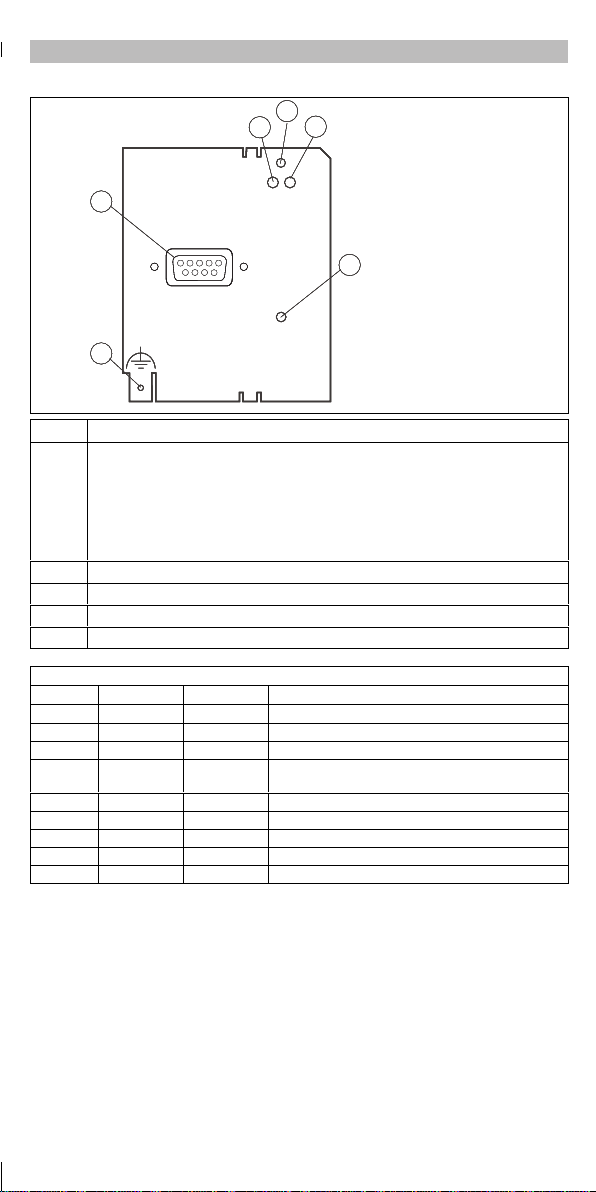
Pos . Bezeichnung/Bedeutung
grüne LED der Spannungsversorgung des Kommunikationsmoduls 2103
AN:
Kommunikationsmodul 2103 ist mit Spannung versorgt und hat Verbindung zum
1
Antriebsregle r bzw. zur Antriebs-SPS
AUS:
Kommunikationsmodul 2103 wird nicht mit Spannung versorgt.
Antriebsregle r/Antriebs-SPS oder externe Spannungsversorgung ist ausgeschaltet.
2, 3 grüne und rote Drive-LED (DRIVE)
4 9polige SubD-Buchse für RS232-Schnittstelle
5 Befestigungsschraube für das Kommunikationsmodul 2103
6 Anschluß für zusätzliches PE-Schirmkabel
RS232
RS232
RS232
RS232
RS232
L
L
L
L
L
FP-Interface
FP-Interface
FP-Interface
FP-Interface
FP-Interface
2103
2103
2103
2103
2103
5
5
5
5
5
2103FPIxxx
9polige SubD-Buchse für RS232-Schnittstelle
Pin Bezeichnung Ein-/Ausgang Erläuterung
1 - - unbenutzt
2 RxD Eingang Datenempfangsleitung RS232
3 TxD Ausgang Datense ndeleitung RS232
4 DTR Ausga ng Das DTR-Signal (Ausgang) hat ke ine Funktion (dauer-
5 GND - Bezugspotential
6 DSR Eingang Das DSR-Signal (Eingang) hat k eine Funk tion
7 - - unbenutzt
8 - - unbenutzt
9 +5V - max. Ausgangsstrom 50 mA
haft auf + 7V logisch 0)
-2-
MA2103FPI 1.0
Page 3
Installation
Show/Hide Bookmarks
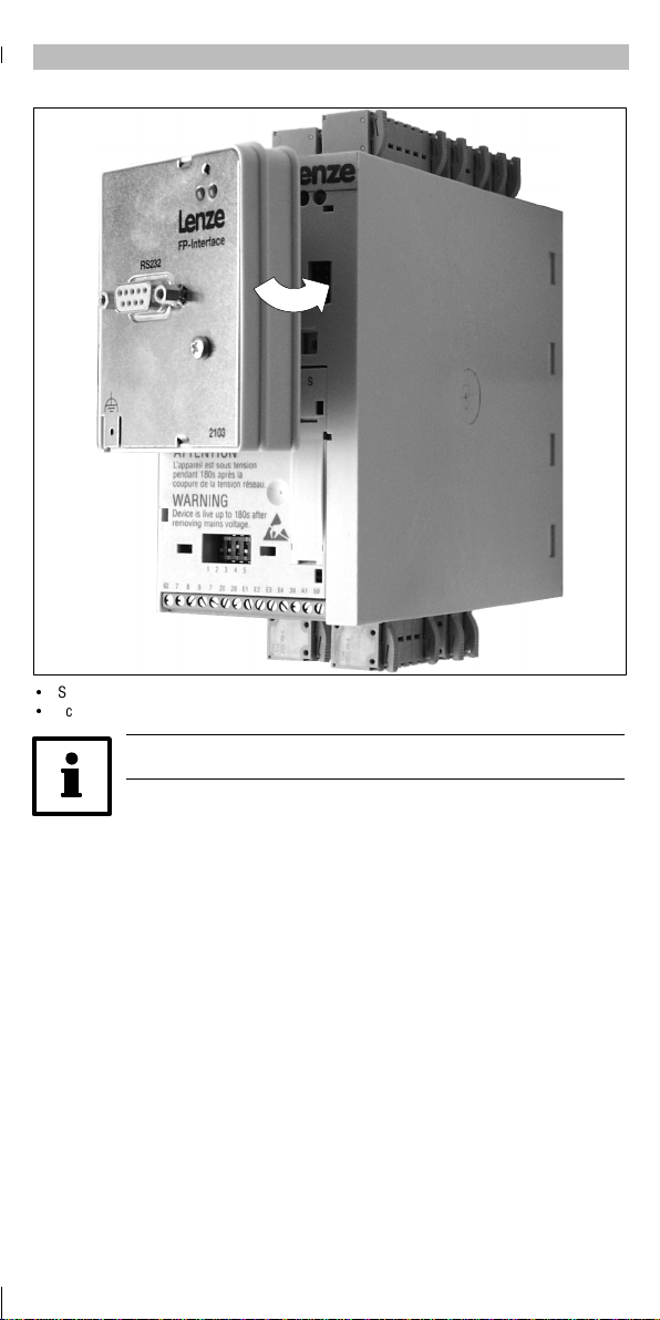
é
Stecken Sie das Kommunikationsmodul auf die Servo PLC 9300 oder die Drive PLC (siehe Abb.).
é
Schrauben Sie das Kommunikationsmodul fest.
Verwenden SiebitteeinPE-Schirmkabel.
-3-
MA2103FPI 1.0
Page 4

Technische Daten
Show/Hide Bookmarks
Bereich
Bestell-Nummer EMF2103IB
Kommunikationsmedien RS 232
Isolations-Spannunge n bei Bussystemen:
é
zur Bezugserde/PE 50 V AC (Potentialtrennung)
é
zum Leistungsteil
- 93XX 270 V AC (doppelte Isolierung)
é
zu de n Steuerklemmen
-DrivePLC 50 V AC (Potentialtrennung)
- 93XX 270 V AC (Basisisolierung)
Umgebungstemperatur im Betrieb:
Feuchtebeanspruchung Klasse 3K3 nach EN 50178 (ohne Betauung, mittlere relative
Wer te
Tra ns po rt :
Lagerung:
Feuchte 85 %)
0°Cbis+55°C
-25°Cbis+70°C
-25°Cbis+60°C
-4-
MA2103FPI 1.0
Page 5
Anhang
Show/Hide Bookmarks
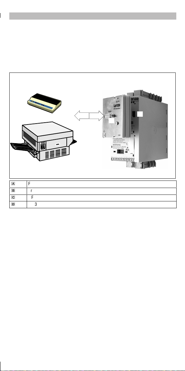
Allgemeines zur Verwendung des Kommunikationsmoduls 2103
MitdemKommunikationsmodul 2103wirddas AIF(Automatisierungsinterface)einer Servo PLC 9300oder
einer Drive PLC zu einer RS232-Schnittstelle erweitert.
Auf der Basis des SPS-Programmierstandards IEC1131-3 kann diese RS232-Schnittstelle mit einem
entsprechenden Anwenderprogramm frei programmiert werden.
Drucker, Modems, Meßgeräte oder andere Komponenten, die über eine serielle RS232-Schnittstelle
kommunizieren, können durch das FP-Interface 2103 in das Automatisierungskonzept integriert werden.
0
FP-Interface (Slave)
1
DrivePLC, siehe Abb., oder Servo PLC 9300 (Master)
2
AIF-Schnittstelle
3
RS232-Schnittstelle
0
1
2
3
-1-
MA2103FPI 1.0
Page 6

EDK2103DB
Show/Hide Bookmarks
00419656
02/01
2103 communication module
FP interface
These Instructions
é
contain the most important technical data and describe the installation of the 2103 communication
module.
é
are only valid
- for communication modules with the nameplate 2103IB
- together with the Operating Instructions of the 9300 servo PLC or the Drive PLC
Description
The 2103 FP interface communication module is a freely programmable RS232 interface.
The communication module can be use d together with the
é
Drive PLC as of na mepla te da ta
- EPL102002X.2X
é
9300 servo PLC as of nameplate data
- 93XX.xx.xx.2x
Pack ing list
1 enclosed 2103 communication module (type of protection: IP20)
1M3fixingscrew
1 Mounting Instructions
Lenze GmbH&CoKG, Postfach 10 13 52, D-31763 Hameln
(
(+49) 5154 82-0, Fax Service: (+49)5154 82-1112
MA2103FPI 1.0
Page 7

Front view
x
Show/Hide Bookmarks
1
1
1
1
1
3
3
3
3
3
2
2
2
2
2
4
4
4
4
4
6
6
6
6
6
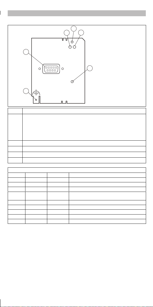
Pos . Name/meaning
green LED for the voltage supply of the 2103 communication module
ON:
The 2103 communication module is supplied with voltage and connected to the controller
1
or Dri ve PLC
OFF:
The 2103 communication module is not supplied with voltage.
Controller/Drive PLC or external volta ge supply is switched off.
2, 3 green and red Drive-LEDs (DRIVE)
4 9-pole SubD connector for RS232 interface
5 Fixing screw for the 2103 communication module
6 Connection for additional shielded PE cable
RS232
RS232
RS232
RS232
RS232
L
L
L
L
L
FP-Interface
FP-Interface
FP-Interface
FP-Interface
FP-Interface
2103
2103
2103
2103
2103
5
5
5
5
5
2103FPIx
9-pole SubD connector for RS232 interface
Pin Name Input/output Explanation
1 - - not assigned
2 RxD Input Cable for receiving data RS232
3 TxD Output Cable for sending data RS232
4 DTR Output The DTR signal (output) is not assigned to a certain
5 GND - Reference potential
6 DSR Input The DSR signal (input) is not assigned to a certain func-
7 - - not assigned
8 - - not assigned
9 +5V - Max. output current: 50 mA
function (+7V permanently, logical 0)
tion
-2-
MA2103FPI 1.0
Page 8

Installation
Show/Hide Bookmarks
é
Plug the communication module onto the 9300 servo PLC or the Drive PLC
(se e fi g. ).
é
Tighten the fixing screw for the communication module.
Please use ashielded PEcable.
-3-
MA2103FPI 1.0
Page 9

Technical data
Show/Hide Bookmarks
Field
Order number EMF2103IB
Communication media RS 232
Insulation volta ges for bus systems:
é
PE 50 V AC (mains isolation)
é
to power stage
- 93XX 270 V AC (double basic insulation)
é
control terminals:
-DrivePLC 50 V AC (mains isolation)
- 93XX 270 V AC (basic insulation)
Ambienttemperature Oper ation :
Permissible humidity Class 3K3 to EN 50178 (without condensation, average relative
Valu es
Tra ns po rt :
Stora ge:
humidity 85 %)
0°Cto+55°C
-25°Cto+70°C
-25°Cto+60°C
-4-
MA2103FPI 1.0
Page 10

Appendix
Show/Hide Bookmarks
General information about the use of the 2103 communication module
The 2103 communication module extends the AIF (automation interface) of a 9300 servo PLC or a Drive
PLC as a RS232 interface.
Using the PLC programming standard IEC1131-3 and a correspondinguser programthisRS232 interface
can be freely programmed.
Withthe 2103 FP interface, printers, modems, measuringdevices andothercomponentscommunicating
via a serial RS232 interface can be integrated into the automation concept.
0
FP interface (slave)
1
DrivePLC, see fig., or 9300 servo PLC (master)
2
AIF inte rface
3
RS232 interface
0
1
2
3
-1-
MA2103FPI 1.0
Page 11

EDK2103DB
Show/Hide Bookmarks
00419656
02/01
Module de communication 2103
Interface FP
Le présent fascic ule
é
contient les principales caractéristiques techniques du module de communication 2103 et décrit
son installation;
é
n’est valable que
- pour les modules de communication 2103IB (voir plaque signalétique),
- conjointement avec les instructions de mise en service du Servo PLC 9300 ou du Drive PLC
concerné.
Description
Le module de communication 2103 interface FP est une interface RS232 programmable.
Il peut être utilisé sur les appareils suivants :
é
DrivePLCàpartirdelaversionsuivante(voirplaquesignalétique):
- EPL102002X.2X
é
Servo PLC 9300 à partir de la version suivante (voir plaque signalétique) :
- 93XX.xx.xx.2x
Equipement livré
1 module de communication 2103 sous coffret (protection IP20)
1 vis de fixation M3
1 documentation ”Instructions de montage”
Lenze GmbH&CoKG, Postfach 10 13 52, D-31763 Hameln
(
(+49) 5154 82-0, Fax Service: (+49)5154 82-1112
MA2103FPI 1.0
Page 12
Vuedeface
Show/Hide Bookmarks
1
1
1
1
1
3
3
3
3
3
2
2
2
2
2
4
4
4
4
4
6
6
6
6
6
Pos . Désignation/signification
LED VERTE pour alimentation du module de communication 2103
ALLUMEE :
Le module de communication 2103 est alimenté et est relié au varia teur/à l’API.
1
ETEINTE :
Le module de communication 2103 n’est pas alimenté.
Le variateur/API est hors tensionou l’alimentation externe est coupée.
2, 3 LED DRI VE VE RTE ou ROUGE (DRIV E)
4 Connecteur SubD 9 broches femelle pour l’interface RS232
5 Vis de fixation pour le module de communication 2103
6 Raccordement pour blindage supplémentaire du câble PE
RS232
RS232
RS232
RS232
RS232
L
L
L
L
L
FP-Interface
FP-Interface
FP-Interface
FP-Interface
FP-Interface
2103
2103
2103
2103
2103
5
5
5
5
5
2103FPIxxx
Connecteur SubD 9 broches femelle pour l’interface RS232
Broche Désignation Entrée/sortie Explication
1 - - Non utilisiée
2 RxD Entrée Ligne de réception de données RS232
3 TxD Sor tie Ligne d’ envoi de donnée s RS232
4 DTR Sortie Le signal DTR (sortie) n’a pas de fonction (en
5 GND - Potentiel de référence
6 DSR Entrée Le signalDSR(entrée) n’a pas de fonction.
7 - - Non utilisée
8 - - Non utilisée
9 +5V - Courantdesortiemaxi50mA
permanence à +7V : 0 logique ).
-2-
MA2103FPI 1.0
Page 13

Installation
Show/Hide Bookmarks
é
Enficher le module de communication dans le Servo PLC 9300 ou le Drive PLC (voir illustration).
é
Visserlemoduledecommunication.
Utiliser un câble PE blindé.
-3-
MA2103FPI 1.0
Page 14

Spécifications techniques
Show/Hide Bookmarks
Domain e
Référence de commande EMF2103IB
Support de communicat ion RS 232
Tensions d’isole ment :
é
Bus - Point de terre/PE 50 V CA (isolation galvanique)
é
Bus - Partie puissance
- 93XX 270 V CA (double isolation)
é
Bus - Bornier de commande
-DrivePLC 50 V CA (isolation galvanique)
- 93XX 270 V CA (isolation de base)
Température a mbiante Fonctionnement
Humidit é a dmissibl e Classe 3K3 selon EN 50178 (sans condensation, humidité
Données
Tra ns po rt
Stock age
relative moyenne 85 %)
0°Cà+55°C
-25°Cà+70°C
-25°Cà+60°C
-4-
MA2103FPI 1.0
Page 15

Annexe
Show/Hide Bookmarks
Généralités sur l’utilisat ion du module de communication 2103
Enutilisantle moduledecommunication 2103,l’interface d’automatisme AIF d’unServo PLC9300oud’un
Drive PLC devient une interface RS232.
Cette interface RS232 peut être programmée enfonction du programme utilisateur et ce, selon la norme
de programmation d’automates CEI1131-3.
L’interface FP 2103 permet d’intégrer des imprimantes, des modems, des appareils de mesure ou autres
éléments communiquant via l’interface série RS232 dans le système d’automatisme.
0
Interface FP (esclave)
1
DrivePLC (voir illustration)ou Servo PLC 9300 (maître)
2
Inte rfa ce AIF
3
Interface RS232
0
1
2
3
-1-
MA2103FPI 1.0
 Loading...