

Page 1
EDK94AYCEO
.I4u
L−force Communication
Montageanleitung
Mounting Instructions
Instructions de montage
Instrucciones para el montaje
Istruzioni per il montaggio
EtherNet/IP
Ä.I4uä
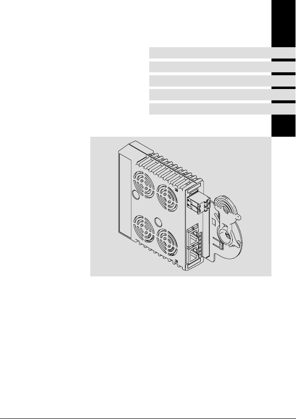
E94AYCEO
Kommunikationsmodul
Communication module
Module de communication
Módulo de comunicación
Modulo di comunicazione
Page 2

Lesen Sie zuerst diese Anleitung, bevor Sie mit den Arbeiten beginnen!
Beachten Sie die enthaltenen Sicherheitshinweise.
Please read these instructions before you start working!
Follow the enclosed safety instructions.
Veuillez lire attentivement cette documentation avant toute action !
Les consignes de sécurité doivent impérativement être respectées.
Lea las instrucciones antes de empezar a trabajar.
Observe las instrucciones de seguridad indicadas.
Prima di usare l’apparecchiatura, leggere le istruzioni contenute in questo
manuale.
Osservare le note di sicurezza.
Page 3
E94YCEO001B
E94AYCET017
Page 4

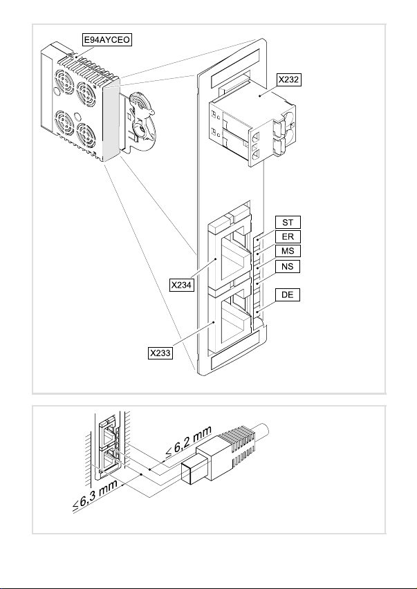
Legende zur Abbildung auf der Ausklappseite
Pos. Beschreibung Ausführliche
X232 Anschluss für externe Spannungsversorgung
l 2−polige Steckerleiste mit Federkraftanschluss
EtherNet/IP−Anschlüsse
X233
l RJ45−Buchsen
X234
l jeweils mit 2 LED−Statusanzeigen zur Diagnose
ST
ER
MS
LED−Statusanzeigen zur Diagnose
NS
DE
0Abb. 0Tab. 0
Information
19
17
21
4
EDK94AYCEO DE/EN/FR/ES/IT 1.0
Page 5

Inhalt i
1 Über diese Dokumentation 6 . . . . . . . . . . . . . . . . . . . . . . . . . . . . . . . . . . . . . . . . . . . .
Verwendete Konventionen 7 . . . . . . . . . . . . . . . . . . . . . . . . . . . . . . . . . . . . . . . . . . . .
Verwendete Hinweise 8 . . . . . . . . . . . . . . . . . . . . . . . . . . . . . . . . . . . . . . . . . . . . . . . .
2 Sicherheitshinweise 10 . . . . . . . . . . . . . . . . . . . . . . . . . . . . . . . . . . . . . . . . . . . . . . . . . .
3 Produktbeschreibung 11 . . . . . . . . . . . . . . . . . . . . . . . . . . . . . . . . . . . . . . . . . . . . . . . .
Funktion 11 . . . . . . . . . . . . . . . . . . . . . . . . . . . . . . . . . . . . . . . . . . . . . . . . . . . . . . . . . . .
Bestimmungsgemäße Verwendung 11 . . . . . . . . . . . . . . . . . . . . . . . . . . . . . . . . . . . .
Lieferumfang 11 . . . . . . . . . . . . . . . . . . . . . . . . . . . . . . . . . . . . . . . . . . . . . . . . . . . . . . .
Identifikation 12 . . . . . . . . . . . . . . . . . . . . . . . . . . . . . . . . . . . . . . . . . . . . . . . . . . . . . . .
4 Technische Daten 13 . . . . . . . . . . . . . . . . . . . . . . . . . . . . . . . . . . . . . . . . . . . . . . . . . . . .
Allgemeine Daten 13 . . . . . . . . . . . . . . . . . . . . . . . . . . . . . . . . . . . . . . . . . . . . . . . . . . .
Abmessungen 14 . . . . . . . . . . . . . . . . . . . . . . . . . . . . . . . . . . . . . . . . . . . . . . . . . . . . . . .
5 Mechanische Installation 15 . . . . . . . . . . . . . . . . . . . . . . . . . . . . . . . . . . . . . . . . . . . . .
6 Elektrische Installation 16 . . . . . . . . . . . . . . . . . . . . . . . . . . . . . . . . . . . . . . . . . . . . . . .
EMV−gerechte Verdrahtung 16 . . . . . . . . . . . . . . . . . . . . . . . . . . . . . . . . . . . . . . . . . . .
EtherNet/IP−Anschluss 17 . . . . . . . . . . . . . . . . . . . . . . . . . . . . . . . . . . . . . . . . . . . . . . .
Externe Spannungsversorgung 19 . . . . . . . . . . . . . . . . . . . . . . . . . . . . . . . . . . . . . . .
7 Inbetriebnahme 20 . . . . . . . . . . . . . . . . . . . . . . . . . . . . . . . . . . . . . . . . . . . . . . . . . . . . .
Vor dem ersten Einschalten 20 . . . . . . . . . . . . . . . . . . . . . . . . . . . . . . . . . . . . . . . . . . .
8 Diagnose 21 . . . . . . . . . . . . . . . . . . . . . . . . . . . . . . . . . . . . . . . . . . . . . . . . . . . . . . . . . . .
LED−Statusanzeigen 21 . . . . . . . . . . . . . . . . . . . . . . . . . . . . . . . . . . . . . . . . . . . . . . . . .
EDK94AYCEO DE/EN/FR/ES/IT 1.0
5
Page 6

1 Über diese Dokumentation
1 Über diese Dokumentation
Inhalt
Diese Dokumentation enthält ...
ƒ Informationen zur mechanischen und elektrischen Installation des
Kommunikationsmoduls;
ƒ Sicherheitshinweise, die Sie unbedingt beachten müssen;
ƒ Angaben über Versionsstände der zu verwendenden Lenze Grundgeräte;
ƒ Informationen zu den LED−Statusanzeigen.
Informationen zur Gültigkeit
Die Informationen in dieser Dokumentation sind gültig für folgende Geräte:
Erweiterungsmodul Typenbezeichnung ab Hardwarestand ab Softwarestand
EtherNet/IP E94AYCEO VE 00.03.00.00
Zielgruppe
Diese Dokumentation richtet sich an Personen, die die Vernetzung und Fernwartung einer
Maschine projektieren, installieren, in Betrieb nehmen und warten.
Tipp!
Informationen und Hilfsmittel rund um die Lenze−Produkte finden Sie im
Download−Bereich unter
http://www.Lenze.com
6
EDK94AYCEO DE/EN/FR/ES/IT 1.0
Page 7

Über diese Dokumentation
Verwendete Konventionen
Verwendete Konventionen
Diese Dokumentation verwendet folgende Konventionen zur Unterscheidung verschiedener Arten von Information:
Informationsart Auszeichnung Beispiele/Hinweise
Zahlenschreibweise
Dezimaltrennzeichen
Symbole
Seitenverweis
Punkt Es wird generell der Dezimalpunkt
verwendet.
Beispiel: 1234.56
Verweis auf eine andere Seite mit zusätzlichen Informationen
Beispiel: 16 = siehe Seite 16
1
EDK94AYCEO DE/EN/FR/ES/IT 1.0
7
Page 8
1 Über diese Dokumentation
Verwendete Hinweise
Verwendete Hinweise
Um auf Gefahren und wichtige Informationen hinzuweisen, werden in dieser Dokumentation folgende Piktogramme und Signalwörter verwendet:
Sicherheitshinweise
Aufbau der Sicherheitshinweise:
Gefahr!
(kennzeichnet die Art und die Schwere der Gefahr)
Hinweistext
(beschreibt die Gefahr und gibt Hinweise, wie sie vermieden werden kann)
Piktogramm und Signalwort Bedeutung
Gefahr von Personenschäden durch gefährliche elektrische Spannung
Gefahr!
Gefahr!
Stop!
Hinweis auf eine unmittelbar drohende Gefahr, die den
Tod oder schwere Verletzungen zur Folge haben kann,
wenn nicht die entsprechenden Maßnahmen getroffen
werden.
Gefahr von Personenschäden durch eine allgemeine Gefahrenquelle
Hinweis auf eine unmittelbar drohende Gefahr, die den
Tod oder schwere Verletzungen zur Folge haben kann,
wenn nicht die entsprechenden Maßnahmen getroffen
werden.
Gefahr von Sachschäden
Hinweis auf eine mögliche Gefahr, die Sachschäden zur
Folge haben kann, wenn nicht die entsprechenden Maßnahmen getroffen werden.
8
EDK94AYCEO DE/EN/FR/ES/IT 1.0
Page 9

Anwendungshinweise
Piktogramm und Signalwort Bedeutung
Über diese Dokumentation
Verwendete Hinweise
1
Hinweis!
Tipp!
Wichtiger Hinweis für die störungsfreie Funktion
Nützlicher Tipp für die einfache Handhabung
Verweis auf andere Dokumentation
EDK94AYCEO DE/EN/FR/ES/IT 1.0
9
Page 10

2 Sicherheitshinweise
2 Sicherheitshinweise
Gefahr!
Unsachgemäßer Umgang mit dem Kommunikationsmodul und dem
Grundgerät kann schwere Personenschäden und Sachschäden verursachen.
Beachten Sie die in der Dokumentation zum Grundgerät enthaltenen
Sicherheitshinweise und Restgefahren.
Stop!
Elektrostatische Entladung
Durch elektrostatische Entladung können elektronische Bauteile innerhalb des
Kommunikationsmoduls beschädigt oder zerstört werden.
Mögliche Folgen:
ƒ Das Kommunikationsmodul ist defekt.
ƒ Die Feldbus−Kommunikation ist nicht möglich oder fehlerhaft.
Schutzmaßnahmen
ƒ Befreien Sie sich vor dem Berühren des Moduls von elektrostatischen
Aufladungen.
10
EDK94AYCEO DE/EN/FR/ES/IT 1.0
Page 11

Produktbeschreibung
Funktion
3 Produktbeschreibung
Funktion
Das Kommunikationsmodul koppelt Lenze Servo Drives 9400 an das Kommunikationssystem EtherNet/IP.
Bestimmungsgemäße Verwendung
Das Kommunikationsmodul ...
ƒ ist eine Zubehör−Baugruppe, die mit folgenden Lenze Grundgeräten eingesetzt
werden kann:
Produktreihe Typenbezeichnung ab Hardwarestand ab Softwarestand
Servo Drives 9400 HighLine E94AxHExxxx 1A 04.00
Servo Drives 9400 PLC E94AxPExxxx VA 02.00
Versorgungs− und Rückspeisemodul
ƒ ist ein Betriebsmittel zum Einsatz in industriellen Starkstromanlagen.
ƒ nur in EtherNet/IP−Netzwerken einsetzen.
Jede andere Verwendung gilt als sachwidrig!
Lieferumfang
ƒ Kommunikationsmodul E94AYCEO (EtherNet/IP)
ƒ Montageanleitung
E94ARNxxxx VA 01.00
Tipp!
Weiterführende Informationen zu diesem Kommunikationsmodul finden Sie
im entsprechenden Kommunikationshandbuch.
Die PDF−Datei finden Sie im Download−Bereich unter
http://www.Lenze.com
3
EDK94AYCEO DE/EN/FR/ES/IT 1.0
11
Page 12
3 Produktbeschreibung
Identifikation
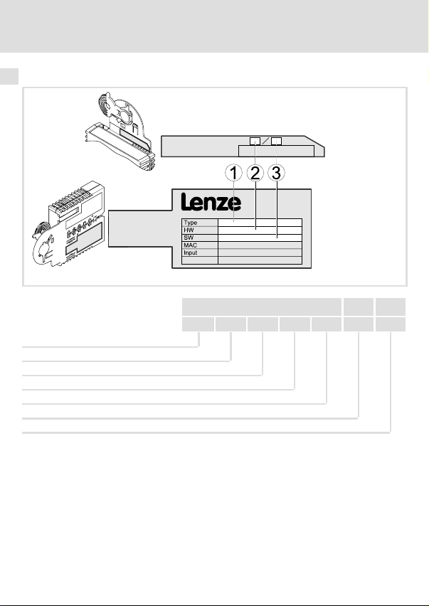
Identifikation
Produktreihe
Gerätegeneration
Modulkennung: Erweiterungsmodul
Modultyp: Kommunikationsmodul
EtherNet/IP
Hardwarestand
Softwarestand
12
E94YCET005
E94 A Y C EO VE 1.00
EDK94AYCEO DE/EN/FR/ES/IT 1.0
Page 13
Technische Daten
Allgemeine Daten
4 Technische Daten
Allgemeine Daten
Bereich Werte
Bestell−Bezeichnung E94AYCEO
Kommunikationsprofil EtherNet/IP
Kommunikationsmedium S/FTP (Screened Foiled Twisted Pair), ISO/IEC 11801 oder EN 50173,
Schnittstelle für Kommunikation
Teilnehmertyp Adapter (Slave)
Teilnehmeranzahl max. 254 im Subnetz
Max. Leitungslänge 100 m
Vendor−ID 587 (0x24B), Lenze (´Lenze AC Tech´ in älteren Rockwell−Daten)
Gerätetyp (Device type) 43 (0x2B), Generic device
Produkt−Code 9400 (0x24B8)
TCP−Port 9410 (GCI)
Übertragungsrate
Übertragungsmodus Halbduplex / Vollduplex
Switching−Methode Store−and−Forward
Switch−Latenzzeit
Spannungsversorgung Externe Versorgung über separates Netzteil
Konformitäten,
Approbationen
CAT 5e
RJ45: Standard Ethernet (nach IEEE 802.3), 100Base−TX (Fast Ethernet)
l 10 MBit/s
l 100 MBit/s
ca. 125 μs bei maximaler Telegrammlänge
l "+": U = 24 V DC (20.4 V...28.8 V), I = 130 mA
l "−": Bezugspotenzial für externe Spannungsversorgung
l CE
l UL
4
Gerätehandbuch "Servo Drives 9400"
Hier finden Sie die Umgebungsbedingungen und Daten zur
Elektromagnetischen Verträglichkeit (EMV), die auch für das
Kommunikationsmodul gelten.
EDK94AYCEO DE/EN/FR/ES/IT 1.0
13
Page 14
4 Technische Daten
Abmessungen
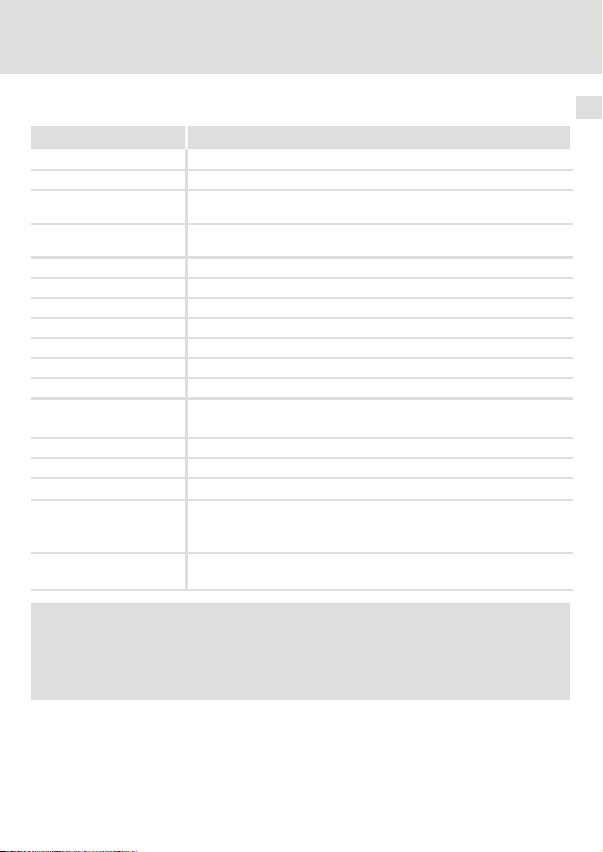
Abmessungen
a89 mm
b 134 mm
b1 87 mm
e 23 mm
E94YCXX005
14
EDK94AYCEO DE/EN/FR/ES/IT 1.0
Page 15
5 Mechanische Installation
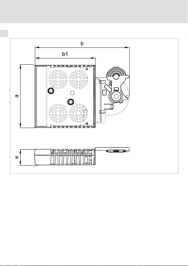
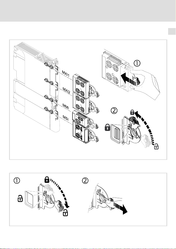
Montage
Demontage
Mechanische Installation 5
E94YCXX001G
EDK94AYCEO DE/EN/FR/ES/IT 1.0
E94AYCXX001H
15
Page 16
6 Elektrische Installation
EMV−gerechte Verdrahtung
6 Elektrische Installation
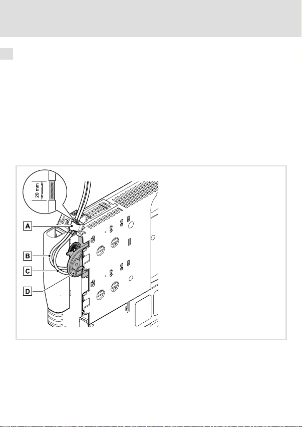
EMV−gerechte Verdrahtung
In typischen Anlagen ist die standardmäßige Schirmung der Ethernet−Kabel ausreichend.
In sehr stark gestörten Umgebungen kann eine Verbesserung der EMV−Festigkeit durch
eine zusätzliche beidseitige Erdung des Kabelschirms ermöglicht werden.
Beachten Sie dazu folgende Hinweise:
1. Der Abstand der zusätzlichen Erdung vom Ethernet−Stecker ist abhängig vom
Steckplatz des Moduls. Der Abstand beträgt
– ca. 10 cm für den oberen Steckplatz (MXI1);
– ca. 20 cm für den unteren Steckplatz (MXI2).
2. Entfernen Sie ausgehend von diesem Abstand die Kunststoffumhüllung des Kabels
auf einer Länge von 2 cm.
3. Befestigen Sie den Kabelschirm am Schirmblech des Servo Drive 9400.
A Befestigung am Schirmblech des Servo Drive 9400
B Ethernet−Kabel an X234
C Ethernet−Kabel an X233
D Kommunikationsmodul in Steckplatz MXI1 des Servo Drive 9400
16
E94YCXX008
EDK94AYCEO DE/EN/FR/ES/IT 1.0
Page 17
Elektrische Installation
EtherNet/IP−Anschluss
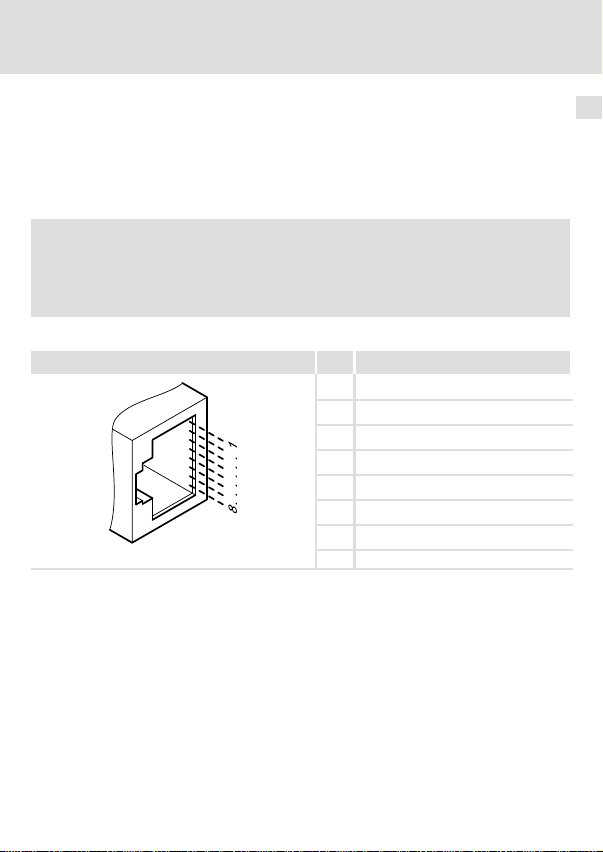
EtherNet/IP−Anschluss
Zum Anschluss des Kommunikationsmoduls an den Feldbus eignet sich ein handelsübliches Standard−Ethernet−Patchkabel (siehe "Spezifikation des Ethernet−Kabels" (18)).
Die Montage und Demontage der Ethernet−Kabel ist optimiert zur Verwendung von Steckverbindern gemäß der "Automation Initiative of German Domestic Automobile Manufacturers" (AIDA).
Hinweis!
Um Beschädigungen der RJ45−Buchse zu vermeiden, den Stecker des
Ethernet−Kabels gerade (im rechten Winkel) in die Buchse stecken bzw. aus der
Buchse ziehen.
Pinbelegung
RJ45−Buchse Pin Signal
1 Tx +
2 Tx −
3 Rx +
4 −
5 −
6 Rx−
7 −
E94AYCXX004C
8 −
Tipp!
Die EtherNet/IP−Schnittstellen verfügen über eine Auto−MDIX−Funktion. Diese
Funktion passt die Polung der RJ45−Schnittstellen so an, dass unabhängig von
der Polung der gegenüberliegenden EtherNet/IP−Schnittstelle und dem
verwendeten Kabeltyp (Standard−Patch−Kabel oder Cross−Over−Kabel) eine
Verbindung hergestellt wird.
6
EDK94AYCEO DE/EN/FR/ES/IT 1.0
17
Page 18
6 Elektrische Installation
EtherNet/IP−Anschluss
Spezifikation des Ethernet−Kabels
Hinweis!
Verwenden Sie ausschließlich Kabel, die den aufgeführten Spezifikationen
entsprechen.
Spezifikation des Ethernet−Kabels
Ethernet−Standard Standard Ethernet (nach IEEE 802.3), 100Base−TX (Fast Ethernet)
Kabeltyp S/FTP (Screened Foiled Twisted Pair), ISO/IEC 11801 oder
Dämpfung 23.2 dB (bei 100 MHz und je 100 m)
Nebensprechdämpfung 24 dB (bei 100 MHz und je 100 m)
Rückflussdämpfung 10 dB (je 100 m)
Wellenwiderstand
EN 50173, CAT 5e
100 W
18
EDK94AYCEO DE/EN/FR/ES/IT 1.0
Page 19
Elektrische Installation
Externe Spannungsversorgung
Externe Spannungsversorgung
Hinweis!
Verwenden Sie bei externer Spannungsversorgung und bei größeren
Entfernungen zwischen den Schaltschränken in jedem Schaltschrank immer
ein separates und nach EN 61800−5−1 sicher getrenntes Netzteil
("SELV"/"PELV").
Das Kommunikationsmodul kann extern über separate Versorgungsleitungen an der 2−poligen Steckerleiste X232 mit Spannung versorgt werden.
Die externe Spannungsversorgung des Kommunikationsmoduls ist notwendig, wenn beim
Ausfall der Versorgung des Grundgerätes die Kommunikation über den Feldbus bestehen
bleiben soll.
Belegung der Steckerleiste X232
Bezeichnung Beschreibung
+ U = 24VDC(20.4 V... 28.8 V)
− Bezugspotenzial für externe Spannungsversorgung
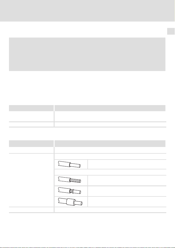
Daten der Anschlussklemmen
Bereich Werte
Elektrischer Anschluss 2−polige Steckerleiste mit Federkraftanschluss
Anschlussmöglichkeiten
Abisolierlänge 9 mm
I = 130 mA
starr:
flexibel:
2
1.5 mm
(AWG 16)
ohne Aderendhülse
2
(AWG 16)
1.5 mm
mit Aderendhülse, ohne Kunststoffhülse
2
(AWG 16)
1.5 mm
mit Aderendhülse, mit Kunststoffhülse
2
(AWG 16)
1.5 mm
6
EDK94AYCEO DE/EN/FR/ES/IT 1.0
19
Page 20

7 Inbetriebnahme
Vor dem ersten Einschalten
7 Inbetriebnahme
Vor dem ersten Einschalten
Stop!
Bevor Sie das Grundgerät mit dem Kommunikationsmodul erstmalig
einschalten, überprüfen Sie die gesamte Verdrahtung auf Vollständigkeit,
Kurzschluss und Erdschluss.
Kommunikationshandbuch E94AYCEO (EtherNet/IP)
Hier finden Sie ausführliche Informationen zur Inbetriebnahme des
Kommunikationsmoduls.
20
EDK94AYCEO DE/EN/FR/ES/IT 1.0
Page 21
Diagnose
LED−Statusanzeigen
8 Diagnose
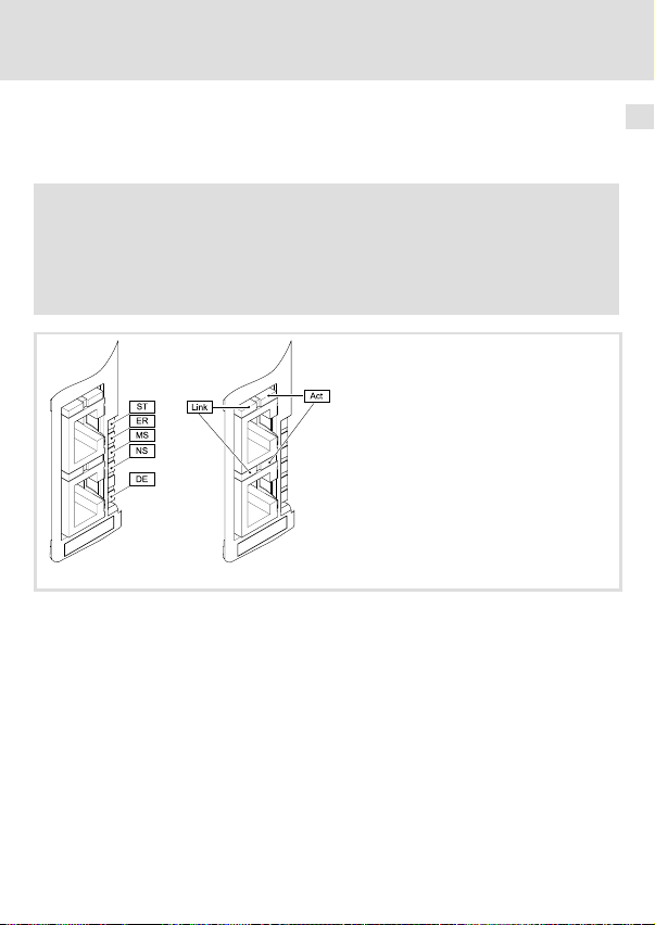
LED−Statusanzeigen
Zur Störungsdiagnose stehen die auf der Frontseite des Kommunikationsmoduls angeordneten LEDs zur Verfügung.
Hinweis!
LED−Statusanzeigen bei fehlerfreiem Betrieb:
ƒ Die LEDs ST und NS leuchten permanent.
ƒ An den RJ45−Buchsen leuchtet jeweils die grüne LED Link und die gelbe LED
Act blinkt oder flackert.
E94AYCEO001E
8
EDK94AYCEO DE/EN/FR/ES/IT 1.0
21
Page 22
8 Diagnose
LED−Statusanzeigen
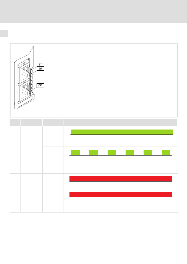
Modul−Statusanzeigen
Modul−Statusanzeigen werden durch die LEDs ST, ER und DE angezeigt.
LED Farbe Zustand Beschreibung
ST grün an
Das Kommunikationsmodul ist mit Spannung versorgt und hat eine
Verbindung zum Grundgerät.
blinkt
ER rot an
DE rot an
250 ms
250 ms
Das Kommunikationsmodul ist mit Spannung versorgt, hat aber
keine Verbindung zum Grundgerät. (Das Grundgerät ist ausgeschaltet, in der Initialisierungsphase oder nicht vorhanden.)
Ein Fehler liegt im Bereich des Kommunikationsmoduls vor.
Das Kommunikationsmodul wird vom Grundgerät nicht akzeptiert
oder das Grundgerät ist nicht aktiv. (Siehe Hinweise in der Dokumentation zum Grundgerät.)
E94YCEO001E
22
EDK94AYCEO DE/EN/FR/ES/IT 1.0
Page 23
LED−Statusanzeigen
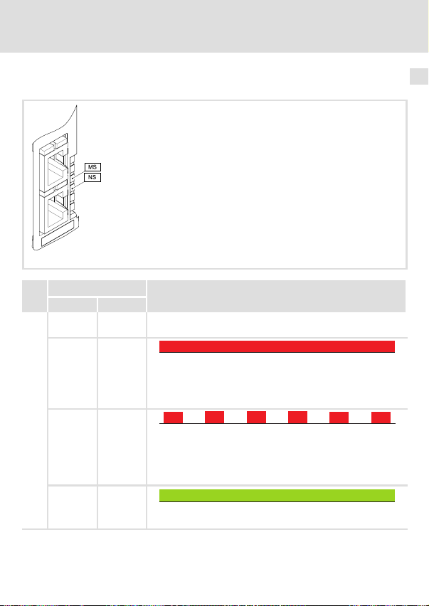
CIP−Statusanzeigen
CIP−Statusanzeigen werden durch die LEDs MS und NS angezeigt.
LED
Farbe / Zustand Beschreibung
grün rot
MS
aus aus CIP−Modulstatus: "Nonexistent"
aus an
aus blinkt
an aus
Das Kommunikationsmodul wird nicht mit Spannung versorgt.
CIP−Modulstatus: "Major Unrecoverable Fault"
Das Kommunikationsmodul weist einen nicht behebbaren Fehler
auf.
Der Status wird gesetzt, wenn der anstehende zustandsbestimmende Gerätefehler die Reaktion Systemfehler hat.
250 ms
250 ms
CIP−Modulstatus: "Major Recoverable Fault"
Das Kommunikationsmodul weist einen behebbaren Fehler auf.
Der Status wird gesetzt, wenn der anstehende zustandsbestimmende Gerätefehler die Reaktion Fehler, Störung, Schnellhalt durch
Störung, arretierte Warnung oder Warnung hat.
CIP−Modulstatus: "Operational"
Das Kommunikationsmodul arbeitet einwandfrei.
Diagnose
E94YCEO001E
8
EDK94AYCEO DE/EN/FR/ES/IT 1.0
23
Page 24

8 Diagnose
LED−Statusanzeigen
LED
MS blinkt aus
blinkt blinkt
NS
aus aus CIP−Netzwerkstatus: "No IP Adress"
aus an
aus blinkt
an aus
blinkt aus
blinkt blinkt
BeschreibungFarbe / ZustandLED
rotgrün
250 ms
250 ms
CIP−Modulstatus: "Standby"
Das Kommunikationsmodul ist noch nicht vollständig konfiguriert
oder die Konfiguration ist fehlerhaft.
250 ms
250 ms
CIP−Modulstatus: "Device Self Testing"
Das Kommunikationsmodul befindet sich im Selbsttest.
Das Kommunikationsmodul wird nicht mit Spannung versorgt oder
hat noch keine IP−Adresse erhalten.
CIP−Netzwerkstatus: "Duplicate IP"
Das Kommunikationsmodul kann nicht auf den Feldbus zugreifen
(IP−Adressenkonflikt).
250 ms
250 ms
CIP−Netzwerkstatus: "Connection Timeout"
Eine Zeitüberschreitung (Timeout) liegt vor.
CIP−Netzwerkstatus: "Connected"
Das Kommunikationsmodul arbeitet einwandfrei und hat eine
Verbindung zum Scanner aufgebaut.
250 ms
250 ms
CIP−Netzwerkstatus: "No Connections"
Das Kommunikationsmodul ...
l arbeitet einwandfrei;
l hat eine IP−Adresse zugewiesen bekommen;
l wurde noch nicht vom Scanner ins Netzwerk eingebunden.
250 ms
250 ms
CIP−Netzwerkstatus: "Self−Test"
Das Kommunikationsmodul befindet sich im Selbsttest.
24
EDK94AYCEO DE/EN/FR/ES/IT 1.0
Page 25
Diagnose
LED−Statusanzeigen
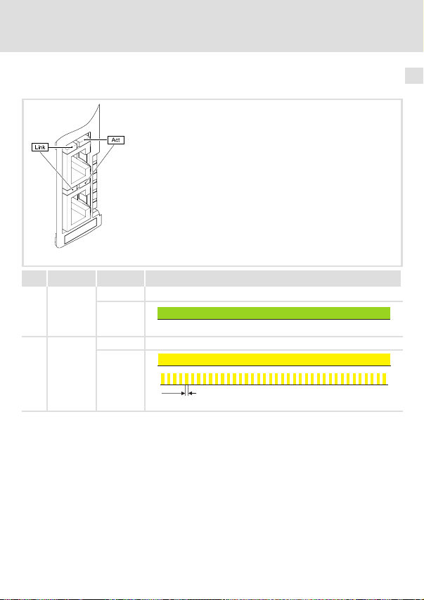
Statusanzeigen an den RJ45−Buchsen (X233, X234)
Die LEDs Link und Act an den RJ45−Buchsen zeigen den Ethernet−Verbindungsstatus an.
E94YCEO001E
LED Farbe Zustand Beschreibung
Link grün
Act gelb
aus Keine Ethernet−Verbindung
an
Physikalische Ethernet−Verbindung ist vorhanden.
aus Kein Ethernet−Datentransfer
an oder
flackert
50 ms
Daten werden über Ethernet ausgetauscht.
8
EDK94AYCEO DE/EN/FR/ES/IT 1.0
25
Page 26

Legend for fold−out page
Pos. Description Detailed
X232 Connection for external voltage supply
l 2−pole plug connector with spring connection
EtherNet/IP connections
X233
l RJ45 sockets
X234
l With 2 LED status displays, respectively, for diagnostics
ST
ER
MS
LED status displays for diagnostics
NS
DE
0Fig. 0Tab. 0
information
41
39
43
26
EDK94AYCEO DE/EN/FR/ES/IT 1.0
Page 27

Contents i
1 About this documentation 28 . . . . . . . . . . . . . . . . . . . . . . . . . . . . . . . . . . . . . . . . . . . .
Conventions used 29 . . . . . . . . . . . . . . . . . . . . . . . . . . . . . . . . . . . . . . . . . . . . . . . . . . . .
Notes used 30 . . . . . . . . . . . . . . . . . . . . . . . . . . . . . . . . . . . . . . . . . . . . . . . . . . . . . . . . .
2 Safety instructions 32 . . . . . . . . . . . . . . . . . . . . . . . . . . . . . . . . . . . . . . . . . . . . . . . . . . .
3 Product description 33 . . . . . . . . . . . . . . . . . . . . . . . . . . . . . . . . . . . . . . . . . . . . . . . . . .
Function 33 . . . . . . . . . . . . . . . . . . . . . . . . . . . . . . . . . . . . . . . . . . . . . . . . . . . . . . . . . . .
Application as directed 33 . . . . . . . . . . . . . . . . . . . . . . . . . . . . . . . . . . . . . . . . . . . . . .
Scope of supply 33 . . . . . . . . . . . . . . . . . . . . . . . . . . . . . . . . . . . . . . . . . . . . . . . . . . . . . .
Identification 34 . . . . . . . . . . . . . . . . . . . . . . . . . . . . . . . . . . . . . . . . . . . . . . . . . . . . . . .
4 Technical data 35 . . . . . . . . . . . . . . . . . . . . . . . . . . . . . . . . . . . . . . . . . . . . . . . . . . . . . . .
General data 35 . . . . . . . . . . . . . . . . . . . . . . . . . . . . . . . . . . . . . . . . . . . . . . . . . . . . . . .
Dimensions 36 . . . . . . . . . . . . . . . . . . . . . . . . . . . . . . . . . . . . . . . . . . . . . . . . . . . . . . . . .
5 Mechanical installation 37 . . . . . . . . . . . . . . . . . . . . . . . . . . . . . . . . . . . . . . . . . . . . . . .
6 Electrical installation 38 . . . . . . . . . . . . . . . . . . . . . . . . . . . . . . . . . . . . . . . . . . . . . . . . .
Wiring according to EMC 38 . . . . . . . . . . . . . . . . . . . . . . . . . . . . . . . . . . . . . . . . . . . . . .
EtherNet/IP connection 39 . . . . . . . . . . . . . . . . . . . . . . . . . . . . . . . . . . . . . . . . . . . . . .
External voltage supply 41 . . . . . . . . . . . . . . . . . . . . . . . . . . . . . . . . . . . . . . . . . . . . . .
7 Commissioning 42 . . . . . . . . . . . . . . . . . . . . . . . . . . . . . . . . . . . . . . . . . . . . . . . . . . . . .
Before switching on 42 . . . . . . . . . . . . . . . . . . . . . . . . . . . . . . . . . . . . . . . . . . . . . . . . .
8 Diagnostics 43 . . . . . . . . . . . . . . . . . . . . . . . . . . . . . . . . . . . . . . . . . . . . . . . . . . . . . . . . .
LED status displays 43 . . . . . . . . . . . . . . . . . . . . . . . . . . . . . . . . . . . . . . . . . . . . . . . . . .
EDK94AYCEO DE/EN/FR/ES/IT 1.0
27
Page 28
1 About this documentation
1 About this documentation
Contents
This documentation contains ...
ƒ information on the mechanical and electrical installation of the communication
module;
ƒ safety instructions which must be observed by all means;
ƒ information about versions of the Lenze standard devices to be used;
ƒ Information on the LED status displays.
Validity information
The information given in this documentation is valid for the following devices:
Extension module Type designation From hardware version From software version
EtherNet/IP E94AYCEO VE 00.03.00.00
Target group
This documentation addresses to persons who project, install, commission, and maintain
the networking and remote maintenance of a machine.
Tip!
Information and auxiliary devices related to the Lenze products can be found
in the download area at
http://www.Lenze.com
28
EDK94AYCEO DE/EN/FR/ES/IT 1.0
Page 29

About this documentation
Conventions used
Conventions used
This documentation uses the following conventions to distinguish between different types
of information:
Type of information Identification Examples/notes
Numbers
Decimal separator
Symbols
Page reference
Point The decimal point is used throughout
this documentation.
Example: 1234.56
Reference to another page with
additional information
Example: 16 = see page 16
1
EDK94AYCEO DE/EN/FR/ES/IT 1.0
29
Page 30
1 About this documentation
Notes used
Notes used
The following pictographs and signal words are used in this documentation to indicate
dangers and important information:
Safety instructions
Structure of safety instructions:
Danger!
(characterises the type and severity of danger)
Note
(describes the danger and gives information about how to prevent dangerous
situations)
Pictograph and signal word Meaning
Danger of personal injury through dangerous electrical
Danger!
Danger!
Stop!
voltage.
Reference to an imminent danger that may result in
death or serious personal injury if the corresponding
measures are not taken.
Danger of personal injury through a general source of
danger.
Reference to an imminent danger that may result in
death or serious personal injury if the corresponding
measures are not taken.
Danger of property damage.
Reference to a possible danger that may result in
property damage if the corresponding measures are not
taken.
30
EDK94AYCEO DE/EN/FR/ES/IT 1.0
Page 31

Application notes
Pictograph and signal word Meaning
About this documentation
Notes used
1
Note!
Tip!
Important note to ensure troublefree operation
Useful tip for simple handling
Reference to another documentation
EDK94AYCEO DE/EN/FR/ES/IT 1.0
31
Page 32

2 Safety instructions
2 Safety instructions
Danger!
Inappropriate handling of the communication module and the standard device
can cause serious personal injury and material damage.
Observe the safety instructions and residual hazards described in the
documentation for the standard device.
Stop!
Electrostatic discharge
Electronic components of the communication module can be damaged or
destroyed through electrostatic discharge.
Possible consequences:
ƒ The communication module is damaged.
ƒ Fieldbus communication is not possible or faulty.
Protective measures
ƒ Discharge electrostatic charges before touching the module.
32
EDK94AYCEO DE/EN/FR/ES/IT 1.0
Page 33

Product description
Function
3 Product description
Function
The communication module connects Lenze Servo Drives 9400 with the EtherNet/IP
communication system.
Application as directed
The communication module ...
ƒ is an accessory module which can be used in conjunction with the following Lenze
standard devices:
Product series Type designation From hardware
Servo Drives 9400 HighLine E94AxHExxxx 1A 04.00
Servo Drives 9400 PLC E94AxPExxxx VA 02.00
Regenerative power supply
module
ƒ is a device to be used in industrial power systems.
ƒ can only be used in EtherNet/IP networks.
Any other use shall be deemed inappropriate!
E94ARNxxxx VA 01.00
version
From software
version
Scope of supply
ƒ E94AYCEO communication module (EtherNet/IP)
ƒ Mounting Instructions
Tip!
Further information regarding this communication module can be found in
the corresponding communication manual.
The PDF file can be found in the download area at
http://www.Lenze.com
3
EDK94AYCEO DE/EN/FR/ES/IT 1.0
33
Page 34

3 Product description
Identification
Identification
Product series
Device generation
Module identification: extension
module
Module type: communication module
EtherNet/IP
Hardware version
Software version
34
E94YCET005
E94 A Y C EO VE 1.00
EDK94AYCEO DE/EN/FR/ES/IT 1.0
Page 35

Technical data
General data
4 Technical data
General data
Field Values
Order designation E94AYCEO
Communication profile EtherNet/IP
Communication medium S/FTP (Screened Foiled Twisted Pair), ISO/IEC 11801 or EN 50173, CAT
Interface for
communication
Node type Adapter (slave)
Number of nodes Max. 254 in the subnetwork
Max. cable length 100 m
Vendor ID 587 (0x24B), Lenze (´Lenze AC Tech´ in older Rockwell data)
Device type 43 (0x2B), Generic device
Product code 9400 (0x24B8)
TCP port 9410 (GCI)
Baud rate
Transmission mode Half duplex / full duplex
Switching method Store−and−Forward
Switch latency
Voltage supply External supply via separate power supply unit
Conformities, approvals
5e
RJ45: Standard Ethernet (according to IEEE 802.3), 100Base−TX (fast
Ethernet)
l 10 Mbps
l 100 MBit/s
Approx. 125 μs for a maximum frame length
l "+": U = 24 V DC (20.4 V...28.8 V), I = 130 mA
l "−": Reference potential for external voltage supply
l CE
l UL
4
"Servo Drives 9400" hardware manual
Here you can find the ambient conditions and the electromagnetic
compatibility (EMC) specifications applying to the communication module.
EDK94AYCEO DE/EN/FR/ES/IT 1.0
35
Page 36

4 Technical data
Dimensions
Dimensions
a89 mm
b 134 mm
b1 87 mm
e 23 mm
E94YCXX005
36
EDK94AYCEO DE/EN/FR/ES/IT 1.0
Page 37

5 Mechanical installation
Mounting
Dismounting
Mechanical installation 5
E94YCXX001G
EDK94AYCEO DE/EN/FR/ES/IT 1.0
E94AYCXX001H
37
Page 38

6 Electrical installation
Wiring according to EMC
6 Electrical installation
Wiring according to EMC
In typical systems, standard shielding of the Ethernet cables is sufficient.
In environments with a very high level of interference, immunity to noise can be improved
by additionally earthing the cable shield on both sides.
Observe the following notes for this:
1. The clearance of the additional earthing from the Ethernet plug depends on the
module slot. The clearance is
– approx. 10 cm for the upper slot (MXI1);
– approx. 20 cm for the lower slot (MXI2).
2. Starting from this clearance, remove the plastic sheath of the cable on a length of
2 cm.
3. Mount the cable shield on the shield sheet of the Servo Drive 9400.
A Connection to the shield sheet of Servo Drive 9400
B Ethernet cable at X234
C Ethernet cable at X233
D Communication module in slot MXI1 of Servo Drive 9400
38
E94YCXX008
EDK94AYCEO DE/EN/FR/ES/IT 1.0
Page 39

Electrical installation
EtherNet/IP connection
EtherNet/IP connection
You can use a standard Ethernet patch cable for connecting the communication module to
the fieldbus (see "Ethernet cable specifications" (40)).
Mounting and dismounting of the Ethernet cables has been optimised for the use of
connectors according to the "Automation Initiative of German Domestic Automobile
Manufacturers" (AIDA).
Note!
Plug/remove the Ethernet cable plug in a straight manner (at right angles)
into/from the socket to make sure that the RJ45 socket will not be damaged.
Pin assignment
RJ45 socket PIN Signal
1 Tx +
2 Tx −
3 Rx +
4 −
5 −
6 Rx −
7 −
E94AYCXX004C
8 −
Tip!
The EtherNet/IP interfaces are equipped with an auto−MDIX function. This
function adapts the polarity of the RJ45 interfaces in a way that,
independently of the polarity of the opposite EtherNet/IP interface and the
cable type used (standard patch cable or crossover cable), a connection is
established.
6
EDK94AYCEO DE/EN/FR/ES/IT 1.0
39
Page 40

6 Electrical installation
EtherNet/IP connection
Ethernet cable specifications
Note!
Only use cables complying with the below specifications.
Ethernet cable specifications
Ethernet standard Standard Ethernet (according to IEEE 802.3), 100base TX (fast
Cable type S/FTP (Screened Foiled Twisted Pair), ISO/IEC 11801 or EN 50173,
Damping 23.2 dB (at 100 MHz and per 100 m)
Crosstalk damping 24 dB (at 100 MHz and per 100 m)
Return loss 10 dB (per 100 m)
Surge impedance
Ethernet)
CAT 5e
100 W
40
EDK94AYCEO DE/EN/FR/ES/IT 1.0
Page 41

Electrical installation
External voltage supply
External voltage supply
Note!
Always use a separate power supply unit in every control cabinet and safely
separate it according to EN 61800−5−1 ("SELV"/"PELV") in the case of external
voltage supply and larger distances between the control cabinets.
The communication module can be supplied with voltage externally via separate supply
cables at the 2−pole X232 plug connector.
The external voltage supply of the communication module is required if communication via
the fieldbus is to be continued in case the supply of the standard device fails.
Assignment of the X232 plug connector
Designation Description
+ V = 24VDC(20.4 V... 28.8 V)
− Reference potential for external voltage supply
Terminal data
Field Values
Electrical connection 2−pin plug connector with spring connection
Possible connections
Stripping length 9 mm
I = 130 mA
rigid:
flexible:
2
1.5 mm
(AWG 16)
without wire end ferrule
2
(AWG 16)
1.5 mm
with wire end ferrule, without plastic sleeve
2
(AWG 16)
1.5 mm
with wire end ferrule, with plastic sleeve
2
(AWG 16)
1.5 mm
6
EDK94AYCEO DE/EN/FR/ES/IT 1.0
41
Page 42

7 Commissioning
Before switching on
7 Commissioning
Before switching on
Stop!
Before switching on the standard device with the communication module for
the first time, check the entire wiring for completeness, short circuit and earth
fault.
E94AYCEO communication manual (EtherNet/IP)
Here you’ll find some detailed information on the commissioning of the
communication module.
42
EDK94AYCEO DE/EN/FR/ES/IT 1.0
Page 43

Diagnostics
LED status displays
8 Diagnostics
LED status displays
The LEDs on the front of the communication module are provided for purposes of fault
diagnostics.
Note!
LED status displays for trouble−free operation:
ƒ The LEDs ST and NS are lit permanently.
ƒ The green LED Link on the RJ45 sockets is lit, respectively, and the yellow
LED Act is blinking or flickering.
E94AYCEO001E
8
EDK94AYCEO DE/EN/FR/ES/IT 1.0
43
Page 44

8 Diagnostics
LED status displays
Module status displays Module status displays are shown by the LEDs ST, ER and DE.
LED Colour Status Description
ST Green On
Communication module is supplied with voltage and has a
Blinking
ER Red On
DE Red On
connection to the standard device.
250 ms
250 ms
The communication module is supplied with voltage, but has no
connection to the standard device. (The standard device is either
switched off, in the initialisation phase, or not available).
There is an error in the area of the communication module.
The communication module is not accepted by the standard device,
or the standard device is not active. (See notes given in the
documentation for the standard device).
E94YCEO001E
44
EDK94AYCEO DE/EN/FR/ES/IT 1.0
Page 45

CIP status displays CIP status displays are shown by the LEDs MS and NS.
LED
Colour / status Description
Green Red
MS
Off Off CIP module status: "Nonexistent"
Off On
Off Blinking
On Off
The communication module is not supplied with voltage.
CIP module status: "Major Unrecoverable Fault"
An unrecoverable error in the communication module has occurred.
The status is set if the pending status determining device error
shows the "System fault" response.
250 ms
250 ms
CIP module status: "Major Recoverable Fault"
A recoverable error in the communication module has occurred.
The status is set if the pending status determining device error
shows the "Fault", "Trouble", "Quick stop by trouble", "Warning
locked", or "Warning" response.
CIP module status: "Operational"
The communication module is working correctly.
Diagnostics
LED status displays
E94YCEO001E
8
EDK94AYCEO DE/EN/FR/ES/IT 1.0
45
Page 46

8 Diagnostics
LED status displays
LED
MS Blinking Off
Blinking Blinking
NS
Off Off CIP network status: "No IP Adress"
Off On
Off Blinking
On Off
Blinking Off
Blinking Blinking
DescriptionColour / statusLED
RedGreen
250 ms
250 ms
CIP module status: "Standby"
The communication module is not fully configured yet, or the
configuration is incorrect.
250 ms
250 ms
CIP module status: "Device Self Testing"
The communication module is performing a self test.
The communication module is not supplied with voltage or has not
received an IP address yet.
CIP network status: "Duplicate IP"
The communication module cannot access the fieldbus (IP address
conflict).
250 ms
250 ms
CIP network status: "Connection Timeout"
A time−out is executed.
CIP network status: "Connected"
The communication module is working correctly and has
established a connection to the scanner.
250 ms
250 ms
CIP network status: "No Connections"
The communication module ...
l is working correctly;
l has been assigned an IP address;
l has not been integrated into the network by the scanner yet.
250 ms
250 ms
CIP network status: "Self−Test"
The communication module is performing a self test.
46
EDK94AYCEO DE/EN/FR/ES/IT 1.0
Page 47

Diagnostics
LED status displays
Status displays at the RJ45 sockets (X233, X234) The LEDs Link and Act at the RJ45 sockets display the Ethernet connection status.
E94YCEO001E
LED Colour Status Description
Link Green
Act yellow
Off No Ethernet connection
On
Physical Ethernet connection is available.
Off No Ethernet data transfer
On or
flickering
50 ms
Data is being exchanged via Ethernet.
8
EDK94AYCEO DE/EN/FR/ES/IT 1.0
47
Page 48

Légende de l’illustration de la page dépliante
Pos. Description Informations
X232 Raccordement pour alimentation externe
l Bornier à lame ressort à 2 bornes
Raccordements EtherNet/IP
X233
l Prises RJ45
X234
l Dotée chacune de 2 LED d’affichage d’état à des fins de diagnostic
ST
ER
MS
Affichage d’état par LED à des fins de diagnostic
NS
DE
0Fig. 0Tab. 0
détaillées
63
61
65
48
EDK94AYCEO DE/EN/FR/ES/IT 1.0
Page 49

Sommaire i
1 Présentation du document 50 . . . . . . . . . . . . . . . . . . . . . . . . . . . . . . . . . . . . . . . . . . . .
Conventions utilisées 51 . . . . . . . . . . . . . . . . . . . . . . . . . . . . . . . . . . . . . . . . . . . . . . . . .
Consignes utilisées 52 . . . . . . . . . . . . . . . . . . . . . . . . . . . . . . . . . . . . . . . . . . . . . . . . . . .
2 Consignes de sécurité 54 . . . . . . . . . . . . . . . . . . . . . . . . . . . . . . . . . . . . . . . . . . . . . . . .
3 Description du produit 55 . . . . . . . . . . . . . . . . . . . . . . . . . . . . . . . . . . . . . . . . . . . . . . . .
Fonction 55 . . . . . . . . . . . . . . . . . . . . . . . . . . . . . . . . . . . . . . . . . . . . . . . . . . . . . . . . . . .
Utilisation conforme à la fonction 55 . . . . . . . . . . . . . . . . . . . . . . . . . . . . . . . . . . . . .
Equipement livré 55 . . . . . . . . . . . . . . . . . . . . . . . . . . . . . . . . . . . . . . . . . . . . . . . . . . . .
Identification 56 . . . . . . . . . . . . . . . . . . . . . . . . . . . . . . . . . . . . . . . . . . . . . . . . . . . . . . .
4 Spécifications techniques 57 . . . . . . . . . . . . . . . . . . . . . . . . . . . . . . . . . . . . . . . . . . . . .
Caractéristiques générales 57 . . . . . . . . . . . . . . . . . . . . . . . . . . . . . . . . . . . . . . . . . . . .
Encombrements 58 . . . . . . . . . . . . . . . . . . . . . . . . . . . . . . . . . . . . . . . . . . . . . . . . . . . . .
5 Installation mécanique 59 . . . . . . . . . . . . . . . . . . . . . . . . . . . . . . . . . . . . . . . . . . . . . . .
6 Installation électrique 60 . . . . . . . . . . . . . . . . . . . . . . . . . . . . . . . . . . . . . . . . . . . . . . . .
Câblage conforme CEM 60 . . . . . . . . . . . . . . . . . . . . . . . . . . . . . . . . . . . . . . . . . . . . . . .
Raccordement EtherNet/IP 61 . . . . . . . . . . . . . . . . . . . . . . . . . . . . . . . . . . . . . . . . . . .
Alimentation externe 63 . . . . . . . . . . . . . . . . . . . . . . . . . . . . . . . . . . . . . . . . . . . . . . . .
7 Mise en service 64 . . . . . . . . . . . . . . . . . . . . . . . . . . . . . . . . . . . . . . . . . . . . . . . . . . . . . .
Avant la première mise sous tension 64 . . . . . . . . . . . . . . . . . . . . . . . . . . . . . . . . . . . .
8 Diagnostic 65 . . . . . . . . . . . . . . . . . . . . . . . . . . . . . . . . . . . . . . . . . . . . . . . . . . . . . . . . . .
Affichages d’état par LED 65 . . . . . . . . . . . . . . . . . . . . . . . . . . . . . . . . . . . . . . . . . . . . .
EDK94AYCEO DE/EN/FR/ES/IT 1.0
49
Page 50

1 Présentation du document
1 Présentation du document
Contenu
Ce document contient ...
ƒ des informations sur l’installation mécanique et électrique du module de
communication ;
ƒ des consignes de sécurité qui doivent impérativement être respectées ;
ƒ des indications sur les versions des appareils de base Lenze à utiliser ;
ƒ des informations sur les affichages d’état par LED.
Validité
Les informations contenues dans le présent document s’appliquent aux appareils suivants :
Module d’extension Référence de
EtherNet/IP E94AYCEO VE 00.03.00.00
Public visé
Cette documentation s’adresse aux personnes chargées de la conception, de l’installation,
de la mise en service et de mise en réseau et de la télémaintenance d’une machine.
commande
A partir de la version
matérielle
A partir de la version
logicielle
Conseil !
Toutes les informations relatives aux produits Lenze peuvent être téléchargées
sur notre site à l’adresse suivante :
http://www.Lenze.com
50
EDK94AYCEO DE/EN/FR/ES/IT 1.0
Page 51

Présentation du document
Conventions utilisées
Conventions utilisées
Pour distinguer les différents types d’information, cette documentation utilise les
conventions suivantes :
Type d’information Aperçu Exemples/remarques
Représentation des chiffres
Séparateur décimal
Pictogrammes
Renvoi à une page
Point Le point décimal est généralement
utilisé.
Exemple : 1234.56
Renvoi à une autre page présentant
des informations supplémentaires
Exemple : 16 = voir page 16
1
EDK94AYCEO DE/EN/FR/ES/IT 1.0
51
Page 52

1 Présentation du document
Consignes utilisées
Consignes utilisées
Pour indiquer des risques et des informations importantes, la présente documentation
utilise les mots et pictogrammes suivants :
Consignes de sécurité
Présentation des consignes de sécurité
Danger !
(Le pictogramme indique le type de risque.)
Explication
(L’explication décrit le risque et les moyens de l’éviter.)
Pictogramme et mot associé Explication
Situation dangereuse pour les personnes en raison d’une
tension électrique élevée
Danger !
Danger !
Stop !
Indication d’un danger imminent qui peut avoir pour
conséquences des blessures mortelles ou très graves en
cas de non−respect des consignes de sécurité
correspondantes
Situation dangereuse pour les personnes en raison d’un
danger d’ordre général
Indication d’un danger imminent qui peut avoir pour
conséquences des blessures mortelles ou très graves en
cas de non−respect des consignes de sécurité
correspondantes
Risques de dégâts matériels
Indication d’un risque potentiel qui peut avoir pour
conséquences des dégâts matériels en cas de non−respect
des consignes de sécurité correspondantes
52
EDK94AYCEO DE/EN/FR/ES/IT 1.0
Page 53

Consignes d’utilisation
Pictogramme et mot associé Explication
Présentation du document
Consignes utilisées
1
Remarque
importante !
Conseil !
Remarque importante pour assurer un fonctionnement
correct
Conseil utile pour faciliter la mise en uvre
Renvoi à une autre documentation
EDK94AYCEO DE/EN/FR/ES/IT 1.0
53
Page 54

2 Consignes de sécurité
2 Consignes de sécurité
Danger !
Toute utilisation non conforme à la fonction du module de communication et
de l’appareil de base risque d’entraîner des blessures graves et des dommages
matériels.
Tenir compte des consignes de sécurité et des dangers résiduels indiqués dans
la documentation de l’appareil de base.
Stop !
Décharge électrostatique
Des composants électroniques à l’intérieur du module de communication
peuvent être endommagés ou détruits par des décharges électrostatiques.
Risques encourus :
ƒ Le module de communication est endommagé.
ƒ La communication par bus de terrain est impossible ou erronée.
Mesures de protection :
ƒ Se libérer des décharges électrostatiques avant toute manipulation du
module de communication.
54
EDK94AYCEO DE/EN/FR/ES/IT 1.0
Page 55

Description du produit
Fonction
3 Description du produit
Fonction
Le module de communication relie les appareils Servo Drives 9400 de Lenze au système de
communication EtherNet/IP.
Utilisation conforme à la fonction
Le module de communication ...
ƒ est un accessoire compatible avec les appareils de base Lenze suivants :
Série d’appareils Référence de
Servo Drives 9400 HighLine E94AxHExxxx 1A 04.00
Servo Drives 9400 PLC E94AxPExxxx VA 02.00
Module d’alimentation et
de renvoi sur le réseau
ƒ est un équipement destiné à être utilisé dans des installations à courant fort,
ƒ ne doit être utilisé que dans des réseaux EtherNet/IP.
Toute autre utilisation est contre−indiquée !
commande
E94ARNxxxx VA 01.00
A partir de la version
matérielle
A partir de la version
logicielle
Equipement livré
ƒ Module de communication E94AYCEO (EtherNet/IP)
ƒ Instructions de montage
Conseil !
Pour plus d’informations sur le module de communication, consulter le
manuel de communication correspondant.
Le fichier au format PDF peut être téléchargé à l’adresse suivante :
http://www.Lenze.com
3
EDK94AYCEO DE/EN/FR/ES/IT 1.0
55
Page 56

3 Description du produit
Identification
Identification
Série d’appareils
Génération d’appareils
Identification du module : module
d’extension
Type de module : module de
communication
EtherNet/IP
Version matérielle
Version logicielle
56
E94YCET005
E94 A Y C EO VE 1.00
EDK94AYCEO DE/EN/FR/ES/IT 1.0
Page 57

Spécifications techniques
Caractéristiques générales
4 Spécifications techniques
Caractéristiques générales
Désignation Valeurs
Référence de commande E94AYCEO
Profil de communication EtherNet/IP
Support de communication S/FTP (Screened Foiled Twisted Pair), ISO/CEI 11801 ou EN 50173,
Interface de
communication
Type de participant Adaptateur (esclave)
Nombre de participants 254 max. dans le sous−réseau
Longueur de câble max. 100 m
Vendor−ID 587 (0x24B), Lenze (´Lenze AC Tech´ dans les anciennes documentations
Type d’appareil (device
type)
Code produit 9400 (0x24B8)
Port TCP 9410 (GCI)
Vitesse de transmission
Mode de transmission Semi−duplex / duplex intégral
Méthode de commutation Store−and−Forward
Temps de latence de
commutation
Alimentation Alimentation externe via bloc d’alimentation séparé
Normes appliquées,
homologations
CAT 5e
RJ45 : Ethernet Standard (selon IEEE 802.3), 100Base−TX (Fast Ethernet)
Rockwell)
43 (0x2B), generic device
l 10 Mbits/s
l 100 Mbits/s
env. 125 μs pour la longueur de télégramme maximale
l "+" : U = 24 V CC (20,4 V...28,8 V), I = 130 mA
l "−" : potentiel de référence pour alimentation externe
l CE
l UL
4
Manuel de l’appareil "Servo Drives 9400"
Ce manuel décrit les conditions ambiantes et les données de compatibilité
électromagnétique (CEM) également valables pour le module de
communication.
EDK94AYCEO DE/EN/FR/ES/IT 1.0
57
Page 58

4 Spécifications techniques
Encombrements
Encombrements
a89 mm
b 134 mm
b1 87 mm
e 23 mm
E94YCXX005
58
EDK94AYCEO DE/EN/FR/ES/IT 1.0
Page 59

5 Installation mécanique
Montage
Démontage
Installation mécanique 5
E94YCXX001G
EDK94AYCEO DE/EN/FR/ES/IT 1.0
E94AYCXX001H
59
Page 60

6 Installation électrique
Câblage conforme CEM
6 Installation électrique
Câblage conforme CEM
Dans les installations types, un blindage standard du câble Ethernet suffit.
Dans les environnements soumis à de fortes perturbations, il est possible d’améliorer la
résistance CEM par une mise à la terre supplémentaire du blindage du câble.
Tenir compte des consignes suivantes :
1. L’écart entre la mise à la terre supplémentaire et le connecteur Ethernet dépend de
l’emplacement du module. Il est
– d’environ 10 cm pour l’emplacement du haut (MXI1) ;
– d’environ 20 cm pour l’emplacement du bas (MXI2).
2. Compte tenu de l’écart indiqué ci−dessus, dénuder le câble sur environ 2 cm.
3. Fixer le blindage du câble à la tôle de blindage de l’appareil Servo Drive 9400.
A Fixation à la tôle de blindage de l’appareil Servo Drive 9400
B Câble Ethernet sur X234
C Câble Ethernet sur X233
D Module de communication dans l’emplacement MXI1 de l’appareil Servo Drive 9400
60
EDK94AYCEO DE/EN/FR/ES/IT 1.0
E94YCXX008
Page 61

Installation électrique
Raccordement EtherNet/IP
Raccordement EtherNet/IP
Le module de communication peut être raccordé au bus de terrain à l’aide d’un câble droit
Ethernet standard en vente dans le commerce (voir "Spécifications du câble Ethernet"
(62)).
Le montage et le démontage des câbles Ethernet sont optimisés grâce à l’utilisation de
connecteurs à fiches, conformément à l’initiative d’automation des fabricants
d’automobiles allemands.
Remarque importante !
Enficher ou retirer le connecteur du câble Ethernet verticalement (angle droit)
afin d’éviter tout endommagement de la prise RJ45.
Affectation des broches
Prise RJ45 Broche Signal
1 Tx +
2 Tx −
3 Rx +
4 −
5 −
6 Rx −
7 −
E94AYCXX004C
8 −
Conseil !
Les interfaces EtherNet/IP sont dotées d’une fonction Auto−MDIX. Celle−ci
permet d’adapter l’affectation des broches des prises RJ45 de manière à
pouvoir établir une liaison indépendamment de l’affectation des broches de
l’autre interface EtherNet/IP raccordée et du type de câble utilisé (câble droit
standard ou câble croisé).
6
EDK94AYCEO DE/EN/FR/ES/IT 1.0
61
Page 62

6 Installation électrique
Raccordement EtherNet/IP
Spécifications du câble Ethernet
Remarque importante !
Utiliser exclusivement des câbles conformes aux spécifications indiquées.
Spécifications du câble Ethernet
Standard Ethernet Ethernet standard (selon IEEE 802.3), 100Base−TX (Fast Ethernet)
Type de câble S/FTP (Screened Foiled Twisted Pair), ISO/CEI 11801 ou EN 50173,
Atténuation 23.2 dB (pour 100 MHz et par segment de 100 m)
Affaiblissement diaphonique 24 dB (pour 100 MHz et par segment de 100 m)
Affaiblissement de régularité 10 dB (par segment de 100 m)
Impédance caractéristique
CAT 5e
100 W
62
EDK94AYCEO DE/EN/FR/ES/IT 1.0
Page 63

Installation électrique
Alimentation externe
Alimentation externe
Remarque importante !
En cas d’alimentation externe et de distances importantes entre les armoires
électriques, toujours utiliser un bloc d’alimentation avec coupure de sécurité
("SELV"/"PELV") distinct et conforme à la norme EN 61800−5−1 pour chaque
armoire électrique.
Le module de communication peut être alimenté par une source externe via des câbles
séparés reliés au bornier 2 broches X232.
L’alimentation externe du module de communication est requise lorsqu’il s’agit de
maintenir la communication par bus de terrain en cas de défaillance de l’alimentation de
l’appareil de base.
Affectation des bornes du bornier X232
Désignation Description
+ U = 24VCC(20.4 V... 28.8 V)
− Potentiel de référence pour alimentation externe
Spécifications pour bornier de raccordement
Domaine Valeurs
Raccordement électrique Bornier à lame ressort 2 bornes
Possibilités de
raccordement
Longueur du fil dénudé 9 mm
I = 130 mA
Rigide :
Flexible :
2
1.5 mm
(AWG 16)
sans embout
2
(AWG 16)
1.5 mm
avec embout, sans cosse en plastique
2
(AWG 16)
1.5 mm
avec embout et cosse en plastique
2
(AWG 16)
1.5 mm
6
EDK94AYCEO DE/EN/FR/ES/IT 1.0
63
Page 64

7 Mise en service
Avant la première mise sous tension
7 Mise en service
Avant la première mise sous tension
Stop !
Avant la première mise sous tension de l’appareil de base avec le module de
communication, vérifier si le câblage a été correctement réalisé dans son
intégralité et rechercher d’éventuels courts−circuits (à la terre).
Manuel de communication E94AYCEO (EtherNet/IP)
Consulter ce document pour des informations détaillées sur la mise en service
du module de communication.
64
EDK94AYCEO DE/EN/FR/ES/IT 1.0
Page 65

Affichages d’état par LED
8 Diagnostic
Affichages d’état par LED
Les LED situées sur la face avant du module de communication permettent de réaliser le
diagnostic des défauts.
Remarque importante !
Affichages d’état par LED en fonctionnement normal :
ƒ Les LED ST et NS sont allumées en continu.
ƒ Au niveau des prises RJ45, la LED verte Link et la LED jaune Act sont
allumées ou clignotent.
E94AYCEO001E
Diagnostic
8
EDK94AYCEO DE/EN/FR/ES/IT 1.0
65
Page 66

8 Diagnostic
Affichages d’état par LED
Affichages d’état du module
Les états du module s’affichent sur les LED ST, ERet DE.
LED Couleur Etat Description
ST Vert On
Le module de communication est sous tension et a établi une liaison
Clignote
ER Rouge On
DE Rouge On
avec l’appareil de base.
ment
250 ms
250 ms
Le module de communication est sous tension mais n’a pas pu
établir la liaison avec l’appareil de base. (L’appareil de base est hors
tension, en phase d’initialisation ou introuvable.)
Une erreur a été détectée au niveau du module de communication.
Le module de communication n’est pas reconnu par l’appareil de
base ou ce dernier n’est pas activé. (Lire les informations fournies
dans la documentation de l’appareil de base.)
E94YCEO001E
66
EDK94AYCEO DE/EN/FR/ES/IT 1.0
Page 67

Affichages d’état CIP
Les états CIP s’affichent sur les LED MS et NS.
Affichages d’état par LED
Diagnostic
8
LED
EDK94AYCEO DE/EN/FR/ES/IT 1.0
Couleur / état Description
Vert Rouge
MS
Off Off Etat du module CIP : "Non existent"
Off On
Off Clignote
On Off
ment
E94YCEO001E
Le module de communication n’est pas sous tension.
Etat du module CIP : "Major Unrecoverable Fault"
Le module de communication est affecté par un problème de
fonctionnement qui ne peut être corrigé.
Cet état est activé lorsque le problème en question déclenche une
erreur système (réaction associée).
250 ms
250 ms
Etat du module CIP : "Major Recoverable Fault"
Le module de communication est affecté par un problème de
fonctionnement qui peut être corrigé.
Cet état est activé lorsque le problème en question déclenche une
erreur, un défaut, un arrêt rapide en cas de défaut, un
avertissement verrouillé ou un avertissement (réaction associée).
Etat du module CIP : "Operational"
Le module de communication fonctionne très bien.
67
Page 68

8 Diagnostic
Affichages d’état par LED
LED
MS Clignote
NS
DescriptionCouleur / étatLED
RougeVert
ment
Clignote
ment
Off
Clignote
ment
Off Off Etat du réseau CIP : "No IP Adress"
250 ms
250 ms
Etat du module CIP : "Standby"
Le module de communication n’a pas été entièrement configuré ou
la configuration est erronée.
250 ms
250 ms
Etat du module CIP : "Device Self Testing"
Le module de communication est en mode auto−test.
Le module de communication n’est pas sous−tension ou ne dispose
pas encore d’une adresse IP.
Off On
Etat du réseau CIP : "Duplicate IP"
Le module de communication n’arrive pas à accéder au bus de
Off Clignote
terrain (conflit d’adresse IP).
ment
250 ms
250 ms
Etat du réseau CIP : "Connection Timeout"
Dépassement de temps (timeout).
On Off
Etat du réseau CIP : "Connected"
Le module de communication fonctionne très bien et a établi une
Clignote
ment
Clignote
ment
Clignote
liaison avec le scanner.
Off
ment
250 ms
250 ms
Etat du réseau CIP : "No Connections"
Le module de communication...
l fonctionne parfaitement ;
l s’est vu affecter une adresse IP ;
l n’a pas encore été intégré au réseau par le scanner.
250 ms
250 ms
Etat du réseau CIP : "Self−Test"
Le module de communication est en mode auto−test.
68
EDK94AYCEO DE/EN/FR/ES/IT 1.0
Page 69

Affichages d’état par LED
Affichages d’état sur les prises RJ45 (X233, X234)
Les LED Link et Act des prises RJ45 indiquent l’état de la liaison Ethernet.
Diagnostic
8
LED Couleur Etat Description
Link Vert
Act Jaune
EDK94AYCEO DE/EN/FR/ES/IT 1.0
Off Absence de liaison Ethernet
On
Présence d’une liaison Ethernet physique
Off Pas de transfert de données Ethernet
On ou
scintille−
ment
50 ms
Echange de données via Ethernet en cours.
E94YCEO001E
69
Page 70

Leyenda de la ilustración del lado abatible
Pos. Descripción Información
X232 Conexión para la alimentación de voltaje externa
l Regleta de conectores de 2 polos con conexión por fuerza de resorte
Conexiones EtherNet/IP
X233
l Conectores RJ45
X234
l cada uno con 2 LEDs de indicación de estado para el diagnóstico
ST
ER
MS
Indicación de estado por LEDs para el diagnóstico
NS
DE
0Fig. 0Tab. 0
detallada
84
82
86
70
EDK94AYCEO DE/EN/FR/ES/IT 1.0
Page 71

Contenido i
1 Acerca de esta documentación 72 . . . . . . . . . . . . . . . . . . . . . . . . . . . . . . . . . . . . . . . . .
Convenciones utilizadas 73 . . . . . . . . . . . . . . . . . . . . . . . . . . . . . . . . . . . . . . . . . . . . . .
Indicaciones utilizadas 74 . . . . . . . . . . . . . . . . . . . . . . . . . . . . . . . . . . . . . . . . . . . . . . . .
2 Instrucciones de seguridad 75 . . . . . . . . . . . . . . . . . . . . . . . . . . . . . . . . . . . . . . . . . . . .
3 Descripción del producto 76 . . . . . . . . . . . . . . . . . . . . . . . . . . . . . . . . . . . . . . . . . . . . .
Función 76 . . . . . . . . . . . . . . . . . . . . . . . . . . . . . . . . . . . . . . . . . . . . . . . . . . . . . . . . . . . .
Uso previsto 76 . . . . . . . . . . . . . . . . . . . . . . . . . . . . . . . . . . . . . . . . . . . . . . . . . . . . . . .
Alcance del suministro 76 . . . . . . . . . . . . . . . . . . . . . . . . . . . . . . . . . . . . . . . . . . . . . . . .
Identificación 77 . . . . . . . . . . . . . . . . . . . . . . . . . . . . . . . . . . . . . . . . . . . . . . . . . . . . . . .
4 Datos técnicos 78 . . . . . . . . . . . . . . . . . . . . . . . . . . . . . . . . . . . . . . . . . . . . . . . . . . . . . .
Datos generales 78 . . . . . . . . . . . . . . . . . . . . . . . . . . . . . . . . . . . . . . . . . . . . . . . . . . . . .
Dimensiones 79 . . . . . . . . . . . . . . . . . . . . . . . . . . . . . . . . . . . . . . . . . . . . . . . . . . . . . . . .
5 Instalación mecánica 80 . . . . . . . . . . . . . . . . . . . . . . . . . . . . . . . . . . . . . . . . . . . . . . . . .
6 Instalación eléctrica 81 . . . . . . . . . . . . . . . . . . . . . . . . . . . . . . . . . . . . . . . . . . . . . . . . . .
Cableado según CEM 81 . . . . . . . . . . . . . . . . . . . . . . . . . . . . . . . . . . . . . . . . . . . . . . . . .
Conexión EtherNet/IP 82 . . . . . . . . . . . . . . . . . . . . . . . . . . . . . . . . . . . . . . . . . . . . . . .
Voltaje de alimentación externo 84 . . . . . . . . . . . . . . . . . . . . . . . . . . . . . . . . . . . . . .
7 Puesta en marcha 85 . . . . . . . . . . . . . . . . . . . . . . . . . . . . . . . . . . . . . . . . . . . . . . . . . . . .
Antes de la primera conexión 85 . . . . . . . . . . . . . . . . . . . . . . . . . . . . . . . . . . . . . . . . . .
8 Diagnóstico 86 . . . . . . . . . . . . . . . . . . . . . . . . . . . . . . . . . . . . . . . . . . . . . . . . . . . . . . . . .
Indicadores de estado LED 86 . . . . . . . . . . . . . . . . . . . . . . . . . . . . . . . . . . . . . . . . . . . .
EDK94AYCEO DE/EN/FR/ES/IT 1.0
71
Page 72

1 Acerca de esta documentación
1 Acerca de esta documentación
Contenido
Esta documentación contiene ...
ƒ Información para la instalación mecánica y eléctrica del módulo de comunicaciones.
ƒ Instrucciones de Seguridad que deben ser aplicadas.
ƒ Datos de las versiones de los equipos básicos Lenze que deben ser utilizados.
ƒ Información sobre la indicación del estado mediante LEDs.
Vigencia de la información
La información contenida en esta documentación es válida para los siguientes equipos:
Módulo de Expansión Denominación de tipo a partir de la versión de
EtherNet/IP E94AYCEO VE 00.03.00.00
Grupo objetivo
Esta documentación está dirigida a aquellas personas que se encargan de la planificación,
instalación, puesta en servicio y mantenimiento de la interconexión y el mantenimiento
remoto de un equipo.
hardware
a partir de la versión de
software
¡Sugerencia!
Encontrará información y recursos sobre los productos de Lenze en el área de
descargas de
http://www.Lenze.com
72
EDK94AYCEO DE/EN/FR/ES/IT 1.0
Page 73

Acerca de esta documentación
Convenciones utilizadas
Convenciones utilizadas
Esta documentación utiliza las siguientes convenciones para distinguir diferentes tipos de
información:
Tipo de información Marcación Ejemplos/indicaciones
Números
Separador decimal
Símbolos
Referencia de página
Punto En general se usa el punto decimal.
Ejemplo: 1234.56
Referencia con información adicional
sobre otra página
Ejemplo: 16 = vea la página 16
1
EDK94AYCEO DE/EN/FR/ES/IT 1.0
73
Page 74

1 Acerca de esta documentación
Indicaciones utilizadas
Indicaciones utilizadas
Para indicar peligros e información importante, se utilizan en esta documentación los
siguientes términos indicativos y símbolos:
Instrucciones de seguridad
Estructura de las instrucciones de seguridad:
¡Peligro!
(indican el tipo y la gravedad del peligro)
Texto indicativo
(describe el peligro y da instrucciones para evitarlo)
Pictograma y término indicativo Significado
Riesgo de daños personales por voltaje eléctrico
¡Peligro!
¡Peligro!
¡Alto!
Instrucciones de uso
Pictograma y término indicativo Significado
Indica un peligro inminente que puede causar la muerte o
lesiones graves si no se toman las medidas adecuadas.
Riesgo de daños personales por una fuente de riesgo
general
Indica un peligro inminente que puede causar la muerte o
lesiones graves si no se toman las medidas adecuadas.
Peligro de daños materiales
Indica un posible riesgo que puede ocasionar daños
materiales si no se toman las medidas adecuadas.
¡Aviso!
¡Sugerencia!
74
Nota importante para el funcionamiento sin fallos
Sugerencia útil para facilitar la operación
Referencia a otra documentación
EDK94AYCEO DE/EN/FR/ES/IT 1.0
Page 75

Instrucciones de seguridad 2
2 Instrucciones de seguridad
¡Peligro!
El uso inapropiado del módulo de comunicaciones y del equipo básico puede
causar accidentes y daños materiales.
Observe las Instrucciones de Seguridad y Riesgos Residuales contenidos en la
documentación del equipo básico.
¡Alto!
Descarga electrostática
A causa de una descarga electrostática podrían resultar dañados o destruidos
componentes electrónicos dentro del módulo de comunicaciones.
Posibles consecuencias
ƒ El módulo de comunicaciones sufre defectos.
ƒ La comunicación con el bus de campo no es posible o aparecen errores.
Medidas de protección
ƒ Antes de tocar el módulo libérese de toda carga electrostática.
EDK94AYCEO DE/EN/FR/ES/IT 1.0
75
Page 76

3 Descripción del producto
Función
3 Descripción del producto
Función
El módulo de comunicaciones se acopla al Lenze Servo Drives 9400 con el sistema de
comunicaciones Ethernet/IP.
Uso previsto
El módulo de comunicaciones...
ƒ es un accesorio que puede conectarse con el siguiente equipo básico Lenze:
Serie de productos Denominación de tipo a partir de la versión
Servo Drives 9400 HighLine E94AxHExxxx 1A 04.00
Servo Drives 9400 PLC E94AxPExxxx VA 02.00
Fuente regenerativa E94ARNxxxx VA 01.00
ƒ es un equipo para aplicación en instalaciones industriales de alta tensión.
ƒ sólo debe conectarse en redes EtherNet/IP.
¡Cualquier otro uso se considera inadecuado!
de hardware
a partir de la versión
de software
Alcance del suministro
ƒ Módulo de comunicaciones E94AYCEO (EtherNet/IP)
ƒ Instrucciones para el montaje
¡Sugerencia!
Encontrará información adicional sobre este módulo de comunicaciones en el
manual de comunicaciones correspondiente.
El archivo en formato PDF se encuentra en la sección de descargas de la
página:
http://www.Lenze.com
76
EDK94AYCEO DE/EN/FR/ES/IT 1.0
Page 77

Identificación
Serie de productos
Versión de equipos
Caracterización del módulo: Módulo de
extensión
Tipo de módulo: Módulo de
comunicaciones
EtherNet/IP
Versión de hardware
Versión de software
Descripción del producto
Identificación
E94YCET005
E94 A Y C EO VE 1.00
3
EDK94AYCEO DE/EN/FR/ES/IT 1.0
77
Page 78

4 Datos técnicos
Datos generales
4 Datos técnicos
Datos generales
Rango Valores
Ref. para pedidos E94AYCEO
Perfil de comunicaciones EtherNet/IP
Medio de comunicación S/FTP (Screened Foiled Twisted Pair), ISO/IEC 11801 o EN 50173, CAT 5e
Interface para la
comunicación
Tipo de dispositivo
participante
Número de dispositivos
participantes
Longitud máx. de cable 100 m
Vendor−ID 587 (0x24B), Lenze (´Lenze AC Tech´ en datos Rockwell antiguos)
Tipo de equipo (device
type)
Código de producto 9400 (0x24B8)
Puerto TCP 9410 (GCI)
Velocidad de transmisión
Modo de transmisión Semidúplex/full dúplex
Método de switching Store−and−Forward
Tiempo de latencia del
switch
Alimentación de voltaje Alimentación externa a través de fuente de red separada
Conformidades,
aprobaciones
RJ45: Ethernet estándar (según IEEE 802.3), 100Base−TX (Fast Ethernet)
Adaptador (esclavo)
máx. 254 en la subred
43 (0x2B), generic device
l 10 MBit/s
l 100 MBit/s
aprox. 125 μs con longitud máxima de telegrama
l "+": U = 24 V DC (20.4 V...28.8 V), I = 130 mA
l "−": potencial de referencia para la alimentación de voltaje externa
l CE
l UL
Manual de dispositivos «Servo Drives 9400»
Aquí encontrará las condiciones del entorno y los datos de compatibilidad
electromagnética (CEM) que se aplican al módulo de comunicaciones.
78
EDK94AYCEO DE/EN/FR/ES/IT 1.0
Page 79

Dimensiones
a89 mm
b 134 mm
b1 87 mm
e 23 mm
Datos técnicos
Dimensiones
E94YCXX005
4
EDK94AYCEO DE/EN/FR/ES/IT 1.0
79
Page 80

5 Instalación mecánica
5 Instalación mecánica
Montaje
Desmontaje
E94YCXX001G
80
E94AYCXX001H
EDK94AYCEO DE/EN/FR/ES/IT 1.0
Page 81

Instalación eléctrica
Cableado según CEM
6 Instalación eléctrica
Cableado según CEM
En instalaciones típicas es suficiente el apantallado estándar de los cables Ethernet.
En instalaciones con fuertes interferencias se puede mejorar la resistencia CEM mediante
una puesta a tierra adicional de la malla del cable a ambos lados.
Para ello, observe las siguientes indicaciones:
1. La distancia entre la puesta a tierra adicional y el conector Ethernet depende del
conector del módulo. La distancia es de
– aprox. 10 cm para el conector superior (MXI1);
– aprox. 20 cm para el conector inferior (MXI2).
2. Partiendo de esta distancia, retire unos 2 cm de la cubierta de plástico del cable.
3. Sujete la malla de cable a la chapa de malla del Servo Drive 9400.
6
A Sujeción a la chapa de apantallamiento del Servo Drive 9400
B Cable Ethernet en X234
C Cable Ethernet en X233
D Módulo de comunicaciones en el conector MXI1 del Servo Drive 9400
EDK94AYCEO DE/EN/FR/ES/IT 1.0
E94YCXX008
81
Page 82

6 Instalación eléctrica
Conexión EtherNet/IP
Conexión EtherNet/IP
Para la conexión del módulo de comunicaciones al bus de campo es adecuado el uso del
cable patch Ethernet estándar disponible en los comercios (véase "Especificación del cable
Ethernet" (83)).
El montaje y desmontaje de los cables Ethernet han sido optimizados para el uso con
conectores enchufables según la «Automation Initiative of German Domestic Automobile
Manufacturers» (AIDA).
¡Aviso!
Para evitar daños en el conector RJ45, inserte y extraiga el conector del cable
Ethernet de forma recta (en ángulo recto) respecto al conector
correspondiente.
Asignación de pins
Conector RJ45 PIN Señal
E94AYCXX004C
1 Tx +
2 Tx −
3 Rx +
4 −
5 −
6 Rx −
7 −
8 −
¡Sugerencia!
Los interfaces de Ethernet/IP disponen de una función Auto−MDIX. Esta
función adapta la polaridad de los interfaces RJ45 de tal manera que se
establece una conexión independientemente de la polaridad del interface
Ethernet/IP y del tipo de cable utilizado (cable patch estándar o cable
crossover).
82
EDK94AYCEO DE/EN/FR/ES/IT 1.0
Page 83

Instalación eléctrica
Conexión EtherNet/IP
Especificación del cable Ethernet
¡Aviso!
Sólo utilice cables conforme a las especificaciones indicadas.
Especificación del cable Ethernet
Ethernet Estándar Ethernet estándar (según IEEE 802.3), 100Base−TX (Fast Ethernet)
Tipo de cable S/FTP (Screened Foiled Twisted Pair), ISO/IEC 11801 o EN 50173,
Atenuación 23.2 dB (a 100 MHz y cada 100 m)
Atenuación diafónica 24 dB (a 100 MHz y cada 100 m)
Atenuación de regularidad 10 dB (cada 100 m)
Impedancia característica
CAT 5e
100 W
6
EDK94AYCEO DE/EN/FR/ES/IT 1.0
83
Page 84

6 Instalación eléctrica
Voltaje de alimentación externo
Voltaje de alimentación externo
¡Aviso!
En caso de que exista un voltaje de alimentación externo y que haya una gran
distancia entre los armarios de distribución, utilice en cada armario de
distribución una fuente de alimentación independiente y con separación
segura conforme a EN 61800−5−1 («SELV»/«PELV»).
El módulo de comunicaciones se puede alimentar con voltaje de forma externa con cables
de suministro separados a través de la regleta de conectores de 2 polos X232.
La alimentación externa del módulo de comunicaciones es necesaria, si en caso de fallo de
la alimentación del equipo básico, debe mantenerse la comunicación a través del bus de
campo.
Asignación de la regleta de conectores X232
Denominación Descripción
+ U = 24VDC(20.4 V... 28.8 V)
− Potencial de referencia para la alimentación de voltaje externa
Datos de los bornes de conexión
Rango Valores
Conexión eléctrica Regleta de conectores de 2 polos con conexión por fuerza de resorte
Posibilidades de conexión
Longitud de aislamiento 9 mm
I = 130 mA
rígido:
flexible:
2
1.5 mm
(AWG 16)
sin terminal grimpado
2
(AWG 16)
1.5 mm
con terminal grimpado, sin terminal de plástico
2
(AWG 16)
1.5 mm
con terminal grimpado, con terminal de plástico
2
(AWG 16)
1.5 mm
84
EDK94AYCEO DE/EN/FR/ES/IT 1.0
Page 85

Puesta en marcha
Antes de la primera conexión
7 Puesta en marcha
Antes de la primera conexión
¡Alto!
Antes de poner en marcha por primera vez el equipo básico con el módulo de
comunicaciones, compruebe que todo el cableado esté completo y que no haya
cortocircuitos ni contactos a tierra.
Manual de comunicaciones E94AYCEO (EtherNet/IP)
Aquí encontrará información detallada sobre la puesta en marcha del módulo
de comunicaciones.
7
EDK94AYCEO DE/EN/FR/ES/IT 1.0
85
Page 86

8 Diagnóstico
Indicadores de estado LED
8 Diagnóstico
Indicadores de estado LED
Para el diagnóstico de fallos se dispone de los LEDs que se encuentran en la cara frontal del
módulo de comunicaciones.
¡Aviso!
Indicaciones de estado mediante LEDs durante el funcionamiento sin errores:
ƒ Los LEDs ST y NS se iluminan de manera permanente.
ƒ En los conectores RJ45 el LED verde Link está encendidoy el LED amarillo
Act parpadea o centellea.
E94AYCEO001E
86
EDK94AYCEO DE/EN/FR/ES/IT 1.0
Page 87

Indicadores de estado LED
Diagnóstico
Indicaciones de estado del módulo
Las indicaciones de estado del módulo se realizan a través de los LEDs ST, ER y DE.
8
LED Color Estado Descripción
ST verde encendido
El módulo de comunicaciones está siendo alimentado con voltaje y
parpadea
ER rojo encendido
DE rojo encendido
EDK94AYCEO DE/EN/FR/ES/IT 1.0
ha establecido una conexión con el equipo básico.
250 ms
El módulo de comunicaciones está siendo alimentado con voltaje,
pero no ha establecido conexión con el equipo básico. (El equipo
básico está desconectado, en fase de inicialización o no está
disponible)
Ha aparecido un error en el ámbito del módulo de comunicaciones.
El módulo de comunicaciones no es aceptado por el equipo básico o
el equipo básico no está activo. (Véase indicaciones en la
documentación del equipo básico.)
250 ms
E94YCEO001E
87
Page 88

8 Diagnóstico
Indicadores de estado LED
Indicaciones de estado CIP Las indicaciones de estado CIP se realizan a través de los LEDs MS y NS.
LED
Color / estado Descripción
verde rojo
MS
apagado apagado Estado del módulo CIP: "Nonexistent"
apagado encendido
apagado parpadea
encendido apagado
El módulo de comunicaciones no está siendo alimentado con
voltaje.
Estado del módulo CIP: "Major Unrecoverable Fault"
El módulo de comunicaciones tiene un error irrecuperable.
Este estado se activa cuando el error del equipo que determina el
estado tiene como reacción un error de sistema.
250 ms
250 ms
Estado del módulo CIP: "Major Recoverable Fault"
El módulo de comunicaciones tiene un error recuperable.
Este estado se activa cuando el error del equipo que determina el
estado tiene como reacción un error, fallo, paro rápido por fallo,
advertencia detenida o advertencia.
Estado del módulo CIP: "Operational"
El módulo de comunicaciones está funcionando perfectamente.
E94YCEO001E
88
EDK94AYCEO DE/EN/FR/ES/IT 1.0
Page 89

Indicadores de estado LED
Diagnóstico
8
LED
MS parpadea apagado
parpadea parpadea
NS
apagado apagado Estado de la red CIP: "No IP Adress"
apagado encendido
apagado parpadea
encendido apagado
parpadea apagado
parpadea parpadea
DescripciónColor / estadoLED
rojoverde
250 ms
250 ms
Estado del módulo CIP: "Standby"
El módulo de comunicaciones no está completamente configurado
aún o la configuración contiene errores.
250 ms
250 ms
Estado del módulo CIP: "Device Self Testing"
El módulo de comunicaciones está realizando un autotest.
El módulo de comunicaciones no está siendo alimentado con voltaje
o no ha obtenido aún una dirección IP.
Estado de la red CIP: "Duplicate IP"
El módulo de comunicaciones no puede acceder al bus de campo
(conflicto de direcciones IP).
250 ms
250 ms
Estado de la red IP: "Connection Timeout"
Se ha sobrepasado el tiempo (Timeout).
Estado de la red CIP: "Connected"
El módulo de comunicaciones está funcionando perfectamente y ha
establecido la conexión con el escáner.
250 ms
250 ms
Estado de la red CIP: "No Connections"
El módulo de comunicaciones ...
l está funcionando perfectamente;
l tiene asignada una dirección IP;
l aún no ha sido incluido en la red por el escáner.
250 ms
250 ms
Estado de la red CIP: "Self−Test"
El módulo de comunicaciones está realizando un autotest.
EDK94AYCEO DE/EN/FR/ES/IT 1.0
89
Page 90

8 Diagnóstico
Indicadores de estado LED
Indicaciones de estado en los conectores RJ45 (X233, X234) Los LEDs Link y Act en los conectores RJ45 indican en estado de conexión de Ethernet.
E94YCEO001E
LED Color Estado Descripción
Link verde
Act amarillo
apagado No hay conexión Ethernet
encendido
apagado No hay transferencia de datos por Ethernet.
encendido
o destelle
Existe una conexión Ethernet física.
ante
50 ms
Se están intercambiando datos por Ethernet.
90
EDK94AYCEO DE/EN/FR/ES/IT 1.0
Page 91

Indicadores de estado LED
Diagnóstico
8
EDK94AYCEO DE/EN/FR/ES/IT 1.0
91
Page 92

Legenda figura su pagina ripiegata
Pos. Descrizione Informazioni
X232 Collegamento per alimentazione esterna
l Morsettiera estraibile a 2 poli con collegamento a molla
Collegamenti EtherNet/IP
X233
l Prese RJ45
X234
l ciascuna con 2 indicatori di stato a LED per la diagnostica
ST
ER
MS
Indicatori di stato a LED per la diagnostica
NS
DE
0Fig. 0Tab. 0
dettagliate
106
104
108
92
EDK94AYCEO DE/EN/FR/ES/IT 1.0
Page 93

Sommario i
1 Informazioni sul manuale 94 . . . . . . . . . . . . . . . . . . . . . . . . . . . . . . . . . . . . . . . . . . . .
Convenzioni utilizzate 95 . . . . . . . . . . . . . . . . . . . . . . . . . . . . . . . . . . . . . . . . . . . . . .
Avvertenze utilizzate 96 . . . . . . . . . . . . . . . . . . . . . . . . . . . . . . . . . . . . . . . . . . . . . . .
2 Informazioni sulla sicurezza 97 . . . . . . . . . . . . . . . . . . . . . . . . . . . . . . . . . . . . . . . . . .
3 Descrizione del prodotto 98 . . . . . . . . . . . . . . . . . . . . . . . . . . . . . . . . . . . . . . . . . . . .
Funzione 98 . . . . . . . . . . . . . . . . . . . . . . . . . . . . . . . . . . . . . . . . . . . . . . . . . . . . . . . . .
Utilizzo conforme 98 . . . . . . . . . . . . . . . . . . . . . . . . . . . . . . . . . . . . . . . . . . . . . . . . .
Oggetto della fornitura 98 . . . . . . . . . . . . . . . . . . . . . . . . . . . . . . . . . . . . . . . . . . . . . .
Identificazione 99 . . . . . . . . . . . . . . . . . . . . . . . . . . . . . . . . . . . . . . . . . . . . . . . . . . . .
4 Dati tecnici 100 . . . . . . . . . . . . . . . . . . . . . . . . . . . . . . . . . . . . . . . . . . . . . . . . . . . . . . . .
Dati generali 100 . . . . . . . . . . . . . . . . . . . . . . . . . . . . . . . . . . . . . . . . . . . . . . . . . . . . . .
Dimensioni 101 . . . . . . . . . . . . . . . . . . . . . . . . . . . . . . . . . . . . . . . . . . . . . . . . . . . . . . .
5 Installazione meccanica 102 . . . . . . . . . . . . . . . . . . . . . . . . . . . . . . . . . . . . . . . . . . . . .
6 Installazione elettrica 103 . . . . . . . . . . . . . . . . . . . . . . . . . . . . . . . . . . . . . . . . . . . . . . .
Cablaggio a norma EMC 103 . . . . . . . . . . . . . . . . . . . . . . . . . . . . . . . . . . . . . . . . . . . . .
Collegamento EtherNet/IP 104 . . . . . . . . . . . . . . . . . . . . . . . . . . . . . . . . . . . . . . . . . .
Alimentazione esterna 106 . . . . . . . . . . . . . . . . . . . . . . . . . . . . . . . . . . . . . . . . . . . . .
7 Messa in servizio 107 . . . . . . . . . . . . . . . . . . . . . . . . . . . . . . . . . . . . . . . . . . . . . . . . . . .
Prima dell’accensione 107 . . . . . . . . . . . . . . . . . . . . . . . . . . . . . . . . . . . . . . . . . . . . . . .
8 Diagnostica 108 . . . . . . . . . . . . . . . . . . . . . . . . . . . . . . . . . . . . . . . . . . . . . . . . . . . . . . .
Indicatori di stato a LED 108 . . . . . . . . . . . . . . . . . . . . . . . . . . . . . . . . . . . . . . . . . . . . .
EDK94AYCEO DE/EN/FR/ES/IT 1.0
93
Page 94

1 Informazioni sul manuale
1 Informazioni sul manuale
Contenuto
La presente documentazione contiene ...
ƒ informazioni sull’installazione meccanica ed elettrica del modulo di comunicazione
ƒ avvertenze sulla sicurezza che dovranno essere obbligatoriamente osservate
ƒ informazioni sulle versioni dei dispositivi base Lenze da utilizzare
ƒ Informazioni sugli indicatori di stato dei LED.
Informazioni sulla validità
Le informazioni contenute nella presente documentazione sono valide per i seguenti
dispositivi:
Modulo di espansione Codice di
EtherNet/IP E94AYCEO VE 00.03.00.00
A chi è rivolta
La presente documentazione è rivolta al personale responsabile della progettazione,
installazione, messa in servizio e manutenzione dei collegamenti di rete e del telecontrollo
di una macchina.
identificazione
a partire dalla versione
hardware
a partire dalla versione
software
Suggerimento:
Per informazioni e altri documenti utili sui prodotti Lenze consultate l’area
download del sito
http://www.Lenze.com
94
EDK94AYCEO DE/EN/FR/ES/IT 1.0
Page 95

Informazioni sul manuale
Convenzioni utilizzate
Convenzioni utilizzate
La presente documentazione utilizza le seguenti convenzioni tipografiche per distinguere
i diversi tipi di informazioni:
Tipo di informazione Convenzione
Modalità di scrittura dei numeri
Separatore decimale
Simboli
Rimando a una pagina
tipografica
Punto Generalmente si utilizza il punto
Esempi/Note
decimale.
Esempio: 1234.56
Rimando a un’altra pagina con
informazioni aggiuntive
Esempio: 16 = si veda pagina 16
1
EDK94AYCEO DE/EN/FR/ES/IT 1.0
95
Page 96

1 Informazioni sul manuale
Avvertenze utilizzate
Avvertenze utilizzate
Per segnalare pericoli ed informazioni importanti, nella presente documentazione sono
riportati i seguenti simboli e parole di segnalazione:
Note di sicurezza
Struttura delle note di sicurezza:
Pericolo!
(indica il tipo e la gravità del pericolo)
Testo della nota
(descrive il pericolo e fornisce indicazioni su come può essere evitato)
Simbolo e parola di segnalazione Significato
Pericolo di danni alle persone dovuti a tensione elettrica
Pericolo!
Pericolo!
Stop!
Note di utilizzo
Simbolo e parola di segnalazione Significato
Avvertenza:
Segnala una situazione di pericolo che può provocare
morte o gravi lesioni se non vengono osservate le
necessarie misure precauzionali.
Pericolo di danni alle persone dovuti a una fonte generica
di pericolo
Segnala una situazione di pericolo che può provocare
morte o gravi lesioni se non vengono osservate le
necessarie misure precauzionali.
Pericolo di danni materiali
Segnala un possibile pericolo che può provocare danni
materiali se non vengono osservate le necessarie misure
precauzionali.
Avvertenza importante per assicurare un corretto
funzionamento dell’apparecchiatura
Suggerimento:
96
Utile suggerimento per un più semplice utilizzo
Rimando ad altra documentazione
EDK94AYCEO DE/EN/FR/ES/IT 1.0
Page 97

Informazioni sulla sicurezza 2
2 Informazioni sulla sicurezza
Pericolo!
Un utilizzo improprio del modulo di comunicazione e del dispositivo base può
causare gravi danni materiali e alle persone.
Rispettare le informazioni sulla sicurezza e sugli altri pericoli contenute nella
documentazione relativa al dispositivo base.
Stop!
Scariche elettrostatiche
Eventuali scariche elettrostatiche possono danneggiare o distruggere le
componenti elettroniche presenti all’interno del modulo di comunicazione.
Possibili conseguenze:
ƒ Malfunzionamento del modulo di comunicazione
ƒ Comunicazione con bus di campo impossibile o problematica.
Misure di protezione
ƒ Prima di toccare il modulo, dissipare le cariche elettrostatiche.
EDK94AYCEO DE/EN/FR/ES/IT 1.0
97
Page 98

3 Descrizione del prodotto
Funzione
3 Descrizione del prodotto
Funzione
Il modulo di comunicazione collega i Servo Drives 9400 Lenze al sistema di comunicazione
EtherNet/IP.
Utilizzo conforme
Il modulo di comunicazione ...
ƒ è un modulo accessorio che può essere impiegato con i seguenti dispositivi base
Lenze:
Serie Codice di
Servo Drives 9400 HighLine E94AxHExxxx 1A 04.00
Servo Drives 9400 PLC E94AxPExxxx VA 02.00
Modulo alimentatore con
recupero in rete
ƒ è un apparecchio destinato all’impiego in impianti industriali ad alta tensione
ƒ da utilizzare solo nelle reti EtherNet/IP.
Ogni altro utilizzo sarà considerato non conforme.
identificazione
E94ARNxxxx VA 01.00
a partire dalla
versione hardware
a partire dalla
versione software
Oggetto della fornitura
ƒ Modulo di comunicazione E94AYCEO (EtherNet/IP)
ƒ Istruzioni di montaggio
Suggerimento:
Informazioni dettagliate su questo modulo di comunicazione sono disponibili
nel relativo manuale di comunicazione.
Il file PDF può essere scaricato nell’area Download all’indirizzo
http://www.Lenze.com
98
EDK94AYCEO DE/EN/FR/ES/IT 1.0
Page 99

Identificazione
Serie
Versione
Identificazione modulo: modulo di
espansione
Tipo di modulo: modulo di
comunicazione
EtherNet/IP
Versione hardware
Versione software
Descrizione del prodotto
Identificazione
E94YCET005
E94 A Y C EO VE 1.00
3
EDK94AYCEO DE/EN/FR/ES/IT 1.0
99
Page 100

4 Dati tecnici
Dati generali
4 Dati tecnici
Dati generali
Ambito Valori
Codice per l’ordine E94AYCEO
Profilo di comunicazione EtherNet/IP
Mezzo di comunicazione S/FTP (Screened Foiled Twisted Pair), ISO/IEC 11801 o EN 50173, CAT 5e
Interfaccia di
comunicazione
Tipo di nodo Adattatore (slave)
Numero di nodi Max. 254 nella sottorete
Lunghezza max. cavo 100 m
Vendor ID 587 (0x24B), Lenze (´Lenze AC Tech´ in dati Rockwell precedenti)
Tipo di dispositivo (Device
type)
Codice prodotto 9400 (0x24B8)
Porta TCP 9410 (GCI)
Velocità di trasmissione
Modo di trasmissione Half−duplex / Full−duplex
Metodo di switching Store−and−Forward
Tempo di latenza switch
Alimentazione Alimentazione esterna con alimentatore separato
Conformità, omologazioni
RJ45: Standard Ethernet (secondo IEEE 802.3), 100Base−TX (Fast
Ethernet)
43 (0x2B), Generic device
l 10 Mbit/s
l 100 Mbit/s
Ca. 125 μs con max. lunghezza del telegramma
l "+": U = 24 V DC (20.4 V...28.8 V), I = 130 mA
l "−": potenziale di riferimento per alimentazione esterna
l CE
l UL
Manuale hardware "Servo Drives 9400"
In questo manuale sono riportati i dati relativi alle condizioni ambientali e alla
compatibilità elettromagnetica (EMC), validi anche per il modulo di
comunicazione.
100
EDK94AYCEO DE/EN/FR/ES/IT 1.0
 Loading...