

Page 1

9400
E94AxPExxxx
Servo Drives 9400 Servo PLC _ _ _ _ _ _ _ _ _ _
Reference manual
EN
Ä.MvIä
13448540
L
Page 2

Overview of technical documentation for Servo Drives 9400
_ _ _ _ _ _ _ _ _ _ _ _ _ _ _ _ _ _ _ _ _ _ _ _ _ _ _ _ _ _ _ _ _ _ _ _ _ _ _ _ _ _ _ _ _ _ _ _ _ _ _ _ _ _ _ _ _ _ _ _ _ _ _ _
Project planning, selection & ordering Legend:
Hardware manual 9400 Printed documentation
Catalogue / electronic catalogue (DSC - Drive Solution Catalogue) Online documentation
(PDF/Engineer online help)
Mounting & wiring Abbreviations used:
MA - 9400 StateLine/HighLine BA Operating Instructions
MA for the communication module KHB Communication manual
MA for the extension module MA Mounting instructions
MA for the safety module SW Software Manual
MA for the accessories
MA - remote maintenance components
Parameter setting
BA keypad
SW - Lenze software »Engineer«
SW - controller (9400 StateLine/HighLine/PLC) This documentation
SW - regenerative power supply module
KHB for the communication module
SW - extension module
SW - safety module
SW - Lenze technology application
SW - function library 9400
Configuring & programming
SW - Lenze software »Engineer«
SW - Lenze software »PLC Designer«
SW - controller (9400 HighLine/PLC) This documentation
KHB for the communication module
SW - extension module
SW - safety module
SW - Lenze technology application
SW - function library 9400
Drive commissioning
Commissioning guide
SW - controller (9400 StateLine/HighLine/PLC) This documentation
Chapter "Commissioning
Chapter "Oscilloscope
Chapter "Diagnostics & fault analysis
Remote maintenance manual
Networking
KHB for the communication medium used
" ( 26)
" ( 611)
" ( 630)
2 Lenze · 9400 Servo PLC· Reference manual · DMS 4.0 EN · 11/2013 · TD05/06
Page 3

Contents
Contents
_ _ _ _ _ _ _ _ _ _ _ _ _ _ _ _ _ _ _ _ _ _ _ _ _ _ _ _ _ _ _ _ _ _ _ _ _ _ _ _ _ _ _ _ _ _ _ _ _ _ _ _ _ _ _ _ _ _ _ _ _ _ _ _
1 About this documentation _ _ _ _ _ _ _ _ _ _ _ _ _ _ _ _ _ _ _ _ _ _ _ _ _ _ _ _ _ _ _ _ _ _ _ _ _ _ _ 15
1.1 Conventions used _ _ _ _ _ _ _ _ _ _ _ _ _ _ _ _ _ _ _ _ _ _ _ _ _ _ _ _ _ _ _ _ _ _ _ _ _ _ _ _ _ _ _ _ 16
1.2 Terminology used _ _ _ _ _ _ _ _ _ _ _ _ _ _ _ _ _ _ _ _ _ _ _ _ _ _ _ _ _ _ _ _ _ _ _ _ _ _ _ _ _ _ _ _ 17
1.3 Definition of the notes used _ _ _ _ _ _ _ _ _ _ _ _ _ _ _ _ _ _ _ _ _ _ _ _ _ _ _ _ _ _ _ _ _ _ _ _ _ _ 18
2Introduction _ _ _ _ _ _ _ _ _ _ _ _ _ _ _ _ _ _ _ _ _ _ _ _ _ _ _ _ _ _ _ _ _ _ _ _ _ _ _ _ _ _ _ _ _ _ _ 19
2.1 Parameter setting, configuring, or programming? _ _ _ _ _ _ _ _ _ _ _ _ _ _ _ _ _ _ _ _ _ _ _ _ _ _ 19
2.1.1 Basic functionalities _ _ _ _ _ _ _ _ _ _ _ _ _ _ _ _ _ _ _ _ _ _ _ _ _ _ _ _ _ _ _ _ _ _ _ _ _ _ 20
2.1.2 Technology applications _ _ _ _ _ _ _ _ _ _ _ _ _ _ _ _ _ _ _ _ _ _ _ _ _ _ _ _ _ _ _ _ _ _ _ _ 20
2.2 Communicating with the controller _ _ _ _ _ _ _ _ _ _ _ _ _ _ _ _ _ _ _ _ _ _ _ _ _ _ _ _ _ _ _ _ _ _ 21
2.2.1 Going online via diagnostic adapter _ _ _ _ _ _ _ _ _ _ _ _ _ _ _ _ _ _ _ _ _ _ _ _ _ _ _ _ _ 21
2.2.2 Going online via system bus (CAN on board) _ _ _ _ _ _ _ _ _ _ _ _ _ _ _ _ _ _ _ _ _ _ _ _ _ 24
2.2.3 Use of other communication interfaces _ _ _ _ _ _ _ _ _ _ _ _ _ _ _ _ _ _ _ _ _ _ _ _ _ _ _ 24
2.3 Signal types & scaling _ _ _ _ _ _ _ _ _ _ _ _ _ _ _ _ _ _ _ _ _ _ _ _ _ _ _ _ _ _ _ _ _ _ _ _ _ _ _ _ _ _ 25
3 Commissioning _ _ _ _ _ _ _ _ _ _ _ _ _ _ _ _ _ _ _ _ _ _ _ _ _ _ _ _ _ _ _ _ _ _ _ _ _ _ _ _ _ _ _ _ _ 26
3.1 General information _ _ _ _ _ _ _ _ _ _ _ _ _ _ _ _ _ _ _ _ _ _ _ _ _ _ _ _ _ _ _ _ _ _ _ _ _ _ _ _ _ _ _ 27
3.2 Notes on commissioning using the keypad _ _ _ _ _ _ _ _ _ _ _ _ _ _ _ _ _ _ _ _ _ _ _ _ _ _ _ _ _ _ 28
3.3 Initial commissioning _ _ _ _ _ _ _ _ _ _ _ _ _ _ _ _ _ _ _ _ _ _ _ _ _ _ _ _ _ _ _ _ _ _ _ _ _ _ _ _ _ _ 29
3.4 Standard set-up _ _ _ _ _ _ _ _ _ _ _ _ _ _ _ _ _ _ _ _ _ _ _ _ _ _ _ _ _ _ _ _ _ _ _ _ _ _ _ _ _ _ _ _ _ 30
3.5 Controller replacement _ _ _ _ _ _ _ _ _ _ _ _ _ _ _ _ _ _ _ _ _ _ _ _ _ _ _ _ _ _ _ _ _ _ _ _ _ _ _ _ _ 31
3.6 Motor replacement _ _ _ _ _ _ _ _ _ _ _ _ _ _ _ _ _ _ _ _ _ _ _ _ _ _ _ _ _ _ _ _ _ _ _ _ _ _ _ _ _ _ _ 31
4 PLC functionality _ _ _ _ _ _ _ _ _ _ _ _ _ _ _ _ _ _ _ _ _ _ _ _ _ _ _ _ _ _ _ _ _ _ _ _ _ _ _ _ _ _ _ _ _ 32
4.1 Setting the controller in »Engineer« _ _ _ _ _ _ _ _ _ _ _ _ _ _ _ _ _ _ _ _ _ _ _ _ _ _ _ _ _ _ _ _ _ _ 33
4.1.1 First steps for setting the controller _ _ _ _ _ _ _ _ _ _ _ _ _ _ _ _ _ _ _ _ _ _ _ _ _ _ _ _ _ _ 34
4.1.2 Export and import of PLC applications _ _ _ _ _ _ _ _ _ _ _ _ _ _ _ _ _ _ _ _ _ _ _ _ _ _ _ _ 35
4.2 Preparations for creating a PLC program _ _ _ _ _ _ _ _ _ _ _ _ _ _ _ _ _ _ _ _ _ _ _ _ _ _ _ _ _ _ _ _ 39
4.2.1 Starting »PLC Designer« from »Engineer« _ _ _ _ _ _ _ _ _ _ _ _ _ _ _ _ _ _ _ _ _ _ _ _ _ _ 39
4.2.1.1 Standard project "PLC_Application.pro" _ _ _ _ _ _ _ _ _ _ _ _ _ _ _ _ _ _ _ _ _ 40
4.2.2 Setting the communication parameters in »PLC Designer« _ _ _ _ _ _ _ _ _ _ _ _ _ _ _ _ _ 41
4.2.3 Selecting libraries _ _ _ _ _ _ _ _ _ _ _ _ _ _ _ _ _ _ _ _ _ _ _ _ _ _ _ _ _ _ _ _ _ _ _ _ _ _ _ 41
4.2.4 Configuring tasks _ _ _ _ _ _ _ _ _ _ _ _ _ _ _ _ _ _ _ _ _ _ _ _ _ _ _ _ _ _ _ _ _ _ _ _ _ _ _ 43
4.2.4.1 Inserting other user tasks _ _ _ _ _ _ _ _ _ _ _ _ _ _ _ _ _ _ _ _ _ _ _ _ _ _ _ _ _ 43
4.2.4.2 Program call _ _ _ _ _ _ _ _ _ _ _ _ _ _ _ _ _ _ _ _ _ _ _ _ _ _ _ _ _ _ _ _ _ _ _ _ 44
4.2.4.3 Configuring system events _ _ _ _ _ _ _ _ _ _ _ _ _ _ _ _ _ _ _ _ _ _ _ _ _ _ _ _ 45
4.2.5 Inserting more user POUs _ _ _ _ _ _ _ _ _ _ _ _ _ _ _ _ _ _ _ _ _ _ _ _ _ _ _ _ _ _ _ _ _ _ _ 46
4.3 Programming notes _ _ _ _ _ _ _ _ _ _ _ _ _ _ _ _ _ _ _ _ _ _ _ _ _ _ _ _ _ _ _ _ _ _ _ _ _ _ _ _ _ _ _ 47
4.3.1 Update function and scaling function _ _ _ _ _ _ _ _ _ _ _ _ _ _ _ _ _ _ _ _ _ _ _ _ _ _ _ _ 47
4.3.2 Creating user-defined codes _ _ _ _ _ _ _ _ _ _ _ _ _ _ _ _ _ _ _ _ _ _ _ _ _ _ _ _ _ _ _ _ _ _ 49
4.3.3 Generating application error messages _ _ _ _ _ _ _ _ _ _ _ _ _ _ _ _ _ _ _ _ _ _ _ _ _ _ _ _ 51
4.4 Use of function blocks _ _ _ _ _ _ _ _ _ _ _ _ _ _ _ _ _ _ _ _ _ _ _ _ _ _ _ _ _ _ _ _ _ _ _ _ _ _ _ _ _ _ 52
4.5 Use of system blocks _ _ _ _ _ _ _ _ _ _ _ _ _ _ _ _ _ _ _ _ _ _ _ _ _ _ _ _ _ _ _ _ _ _ _ _ _ _ _ _ _ _ 54
4.5.1 Access via system variables _ _ _ _ _ _ _ _ _ _ _ _ _ _ _ _ _ _ _ _ _ _ _ _ _ _ _ _ _ _ _ _ _ _ 55
4.5.2 Access via absolute addresses _ _ _ _ _ _ _ _ _ _ _ _ _ _ _ _ _ _ _ _ _ _ _ _ _ _ _ _ _ _ _ _ _ 55
4.5.3 Definition of the inputs and outputs _ _ _ _ _ _ _ _ _ _ _ _ _ _ _ _ _ _ _ _ _ _ _ _ _ _ _ _ _ 55
4.5.4 Implementing system blocks in »PLC Designer« _ _ _ _ _ _ _ _ _ _ _ _ _ _ _ _ _ _ _ _ _ _ _ 56
4.6 Network communication _ _ _ _ _ _ _ _ _ _ _ _ _ _ _ _ _ _ _ _ _ _ _ _ _ _ _ _ _ _ _ _ _ _ _ _ _ _ _ _ 59
4.6.1 Network communication with CAN on board _ _ _ _ _ _ _ _ _ _ _ _ _ _ _ _ _ _ _ _ _ _ _ _ 59
4.6.2 Network communication with fieldbus module _ _ _ _ _ _ _ _ _ _ _ _ _ _ _ _ _ _ _ _ _ _ _ 61
Lenze · 9400 Servo PLC· Reference manual · DMS 4.0 EN · 11/2013 · TD05/06 3
Page 4

Contents
_ _ _ _ _ _ _ _ _ _ _ _ _ _ _ _ _ _ _ _ _ _ _ _ _ _ _ _ _ _ _ _ _ _ _ _ _ _ _ _ _ _ _ _ _ _ _ _ _ _ _ _ _ _ _ _ _ _ _ _ _ _ _ _
4.7 Completing the PLC project _ _ _ _ _ _ _ _ _ _ _ _ _ _ _ _ _ _ _ _ _ _ _ _ _ _ _ _ _ _ _ _ _ _ _ _ _ _ _ 64
4.7.1 Compiling a PLC project _ _ _ _ _ _ _ _ _ _ _ _ _ _ _ _ _ _ _ _ _ _ _ _ _ _ _ _ _ _ _ _ _ _ _ _ 64
4.7.2 Generating a boot project _ _ _ _ _ _ _ _ _ _ _ _ _ _ _ _ _ _ _ _ _ _ _ _ _ _ _ _ _ _ _ _ _ _ _ 64
4.7.3 Saving the PLC project _ _ _ _ _ _ _ _ _ _ _ _ _ _ _ _ _ _ _ _ _ _ _ _ _ _ _ _ _ _ _ _ _ _ _ _ _ 65
4.7.4 Import in the »Engineer« project _ _ _ _ _ _ _ _ _ _ _ _ _ _ _ _ _ _ _ _ _ _ _ _ _ _ _ _ _ _ _ 65
4.7.4.1 Saving the »Engineer« project _ _ _ _ _ _ _ _ _ _ _ _ _ _ _ _ _ _ _ _ _ _ _ _ _ _ 66
4.7.5 Project download _ _ _ _ _ _ _ _ _ _ _ _ _ _ _ _ _ _ _ _ _ _ _ _ _ _ _ _ _ _ _ _ _ _ _ _ _ _ _ 67
4.8 Appendix _ _ _ _ _ _ _ _ _ _ _ _ _ _ _ _ _ _ _ _ _ _ _ _ _ _ _ _ _ _ _ _ _ _ _ _ _ _ _ _ _ _ _ _ _ _ _ _ _ 68
4.8.1 Technical data _ _ _ _ _ _ _ _ _ _ _ _ _ _ _ _ _ _ _ _ _ _ _ _ _ _ _ _ _ _ _ _ _ _ _ _ _ _ _ _ _ 68
4.8.2 Task and timing frame _ _ _ _ _ _ _ _ _ _ _ _ _ _ _ _ _ _ _ _ _ _ _ _ _ _ _ _ _ _ _ _ _ _ _ _ _ 69
4.8.3 User task _ _ _ _ _ _ _ _ _ _ _ _ _ _ _ _ _ _ _ _ _ _ _ _ _ _ _ _ _ _ _ _ _ _ _ _ _ _ _ _ _ _ _ _ 70
4.8.4 Runtime measurement _ _ _ _ _ _ _ _ _ _ _ _ _ _ _ _ _ _ _ _ _ _ _ _ _ _ _ _ _ _ _ _ _ _ _ _ 72
4.8.5 Data consistency _ _ _ _ _ _ _ _ _ _ _ _ _ _ _ _ _ _ _ _ _ _ _ _ _ _ _ _ _ _ _ _ _ _ _ _ _ _ _ _ 73
4.8.6 Storage capacities and memory modules _ _ _ _ _ _ _ _ _ _ _ _ _ _ _ _ _ _ _ _ _ _ _ _ _ _ 73
4.8.7 Known function restrictions of the controller _ _ _ _ _ _ _ _ _ _ _ _ _ _ _ _ _ _ _ _ _ _ _ _ 74
4.8.8 Sample collection for code creation with Pragma instruction _ _ _ _ _ _ _ _ _ _ _ _ _ _ _ _ 76
5 Drive interface _ _ _ _ _ _ _ _ _ _ _ _ _ _ _ _ _ _ _ _ _ _ _ _ _ _ _ _ _ _ _ _ _ _ _ _ _ _ _ _ _ _ _ _ _ _ 79
5.1 Machine parameters _ _ _ _ _ _ _ _ _ _ _ _ _ _ _ _ _ _ _ _ _ _ _ _ _ _ _ _ _ _ _ _ _ _ _ _ _ _ _ _ _ _ 80
5.1.1 Mains voltage _ _ _ _ _ _ _ _ _ _ _ _ _ _ _ _ _ _ _ _ _ _ _ _ _ _ _ _ _ _ _ _ _ _ _ _ _ _ _ _ _ 81
5.1.2 Gearbox ratio _ _ _ _ _ _ _ _ _ _ _ _ _ _ _ _ _ _ _ _ _ _ _ _ _ _ _ _ _ _ _ _ _ _ _ _ _ _ _ _ _ _ 82
5.1.3 Motor mounting direction _ _ _ _ _ _ _ _ _ _ _ _ _ _ _ _ _ _ _ _ _ _ _ _ _ _ _ _ _ _ _ _ _ _ _ 83
5.1.4 Feedback configuration _ _ _ _ _ _ _ _ _ _ _ _ _ _ _ _ _ _ _ _ _ _ _ _ _ _ _ _ _ _ _ _ _ _ _ _ 83
5.1.5 Unit/user-defined unit _ _ _ _ _ _ _ _ _ _ _ _ _ _ _ _ _ _ _ _ _ _ _ _ _ _ _ _ _ _ _ _ _ _ _ _ _ 84
5.1.6 Traversing range _ _ _ _ _ _ _ _ _ _ _ _ _ _ _ _ _ _ _ _ _ _ _ _ _ _ _ _ _ _ _ _ _ _ _ _ _ _ _ _ 85
5.1.7 Feed constant _ _ _ _ _ _ _ _ _ _ _ _ _ _ _ _ _ _ _ _ _ _ _ _ _ _ _ _ _ _ _ _ _ _ _ _ _ _ _ _ _ 87
5.1.8 Resolution of an encoder revolution _ _ _ _ _ _ _ _ _ _ _ _ _ _ _ _ _ _ _ _ _ _ _ _ _ _ _ _ _ 88
5.1.9 Max. position, speed, and acceleration that can be displayed internally _ _ _ _ _ _ _ _ _ _ 91
5.2 Device commands _ _ _ _ _ _ _ _ _ _ _ _ _ _ _ _ _ _ _ _ _ _ _ _ _ _ _ _ _ _ _ _ _ _ _ _ _ _ _ _ _ _ _ _ 92
5.2.1 Load Lenze setting _ _ _ _ _ _ _ _ _ _ _ _ _ _ _ _ _ _ _ _ _ _ _ _ _ _ _ _ _ _ _ _ _ _ _ _ _ _ _ 94
5.2.2 Load start parameters _ _ _ _ _ _ _ _ _ _ _ _ _ _ _ _ _ _ _ _ _ _ _ _ _ _ _ _ _ _ _ _ _ _ _ _ _ 95
5.2.3 ENP:Load plant data _ _ _ _ _ _ _ _ _ _ _ _ _ _ _ _ _ _ _ _ _ _ _ _ _ _ _ _ _ _ _ _ _ _ _ _ _ _ 96
5.2.4 Activate application _ _ _ _ _ _ _ _ _ _ _ _ _ _ _ _ _ _ _ _ _ _ _ _ _ _ _ _ _ _ _ _ _ _ _ _ _ _ 97
5.2.5 Save selected application _ _ _ _ _ _ _ _ _ _ _ _ _ _ _ _ _ _ _ _ _ _ _ _ _ _ _ _ _ _ _ _ _ _ _ 98
5.2.6 Save start parameters _ _ _ _ _ _ _ _ _ _ _ _ _ _ _ _ _ _ _ _ _ _ _ _ _ _ _ _ _ _ _ _ _ _ _ _ _ 99
5.2.7 Delete logbook _ _ _ _ _ _ _ _ _ _ _ _ _ _ _ _ _ _ _ _ _ _ _ _ _ _ _ _ _ _ _ _ _ _ _ _ _ _ _ _ _ 101
5.2.8 Archive logbook _ _ _ _ _ _ _ _ _ _ _ _ _ _ _ _ _ _ _ _ _ _ _ _ _ _ _ _ _ _ _ _ _ _ _ _ _ _ _ _ 102
5.2.9 Start application _ _ _ _ _ _ _ _ _ _ _ _ _ _ _ _ _ _ _ _ _ _ _ _ _ _ _ _ _ _ _ _ _ _ _ _ _ _ _ _ 103
5.2.10 Stop application _ _ _ _ _ _ _ _ _ _ _ _ _ _ _ _ _ _ _ _ _ _ _ _ _ _ _ _ _ _ _ _ _ _ _ _ _ _ _ _ 104
5.2.11 Reset program _ _ _ _ _ _ _ _ _ _ _ _ _ _ _ _ _ _ _ _ _ _ _ _ _ _ _ _ _ _ _ _ _ _ _ _ _ _ _ _ _ 105
5.2.12 Delete program _ _ _ _ _ _ _ _ _ _ _ _ _ _ _ _ _ _ _ _ _ _ _ _ _ _ _ _ _ _ _ _ _ _ _ _ _ _ _ _ 106
5.2.13 Restart program _ _ _ _ _ _ _ _ _ _ _ _ _ _ _ _ _ _ _ _ _ _ _ _ _ _ _ _ _ _ _ _ _ _ _ _ _ _ _ _ 107
5.2.14 Reset runtime measurement _ _ _ _ _ _ _ _ _ _ _ _ _ _ _ _ _ _ _ _ _ _ _ _ _ _ _ _ _ _ _ _ _ 108
5.2.15 Inhibit controller _ _ _ _ _ _ _ _ _ _ _ _ _ _ _ _ _ _ _ _ _ _ _ _ _ _ _ _ _ _ _ _ _ _ _ _ _ _ _ _ 110
5.2.16 Enable controller _ _ _ _ _ _ _ _ _ _ _ _ _ _ _ _ _ _ _ _ _ _ _ _ _ _ _ _ _ _ _ _ _ _ _ _ _ _ _ _ 111
5.2.17 Reset error _ _ _ _ _ _ _ _ _ _ _ _ _ _ _ _ _ _ _ _ _ _ _ _ _ _ _ _ _ _ _ _ _ _ _ _ _ _ _ _ _ _ _ 112
5.2.18 Activate quick stop _ _ _ _ _ _ _ _ _ _ _ _ _ _ _ _ _ _ _ _ _ _ _ _ _ _ _ _ _ _ _ _ _ _ _ _ _ _ _ 113
5.2.19 Reset quick stop _ _ _ _ _ _ _ _ _ _ _ _ _ _ _ _ _ _ _ _ _ _ _ _ _ _ _ _ _ _ _ _ _ _ _ _ _ _ _ _ 114
5.2.20 Identify pole position (360°) _ _ _ _ _ _ _ _ _ _ _ _ _ _ _ _ _ _ _ _ _ _ _ _ _ _ _ _ _ _ _ _ _ _ 115
5.2.21 Identify pole position (min. motion) _ _ _ _ _ _ _ _ _ _ _ _ _ _ _ _ _ _ _ _ _ _ _ _ _ _ _ _ _ 116
5.2.22 Resolver error identification _ _ _ _ _ _ _ _ _ _ _ _ _ _ _ _ _ _ _ _ _ _ _ _ _ _ _ _ _ _ _ _ _ _ 117
5.2.23 Load Lenze INV characteristic _ _ _ _ _ _ _ _ _ _ _ _ _ _ _ _ _ _ _ _ _ _ _ _ _ _ _ _ _ _ _ _ _ 118
5.2.24 Calculate inv. characteristic _ _ _ _ _ _ _ _ _ _ _ _ _ _ _ _ _ _ _ _ _ _ _ _ _ _ _ _ _ _ _ _ _ _ 119
5.2.25 Determine motor parameters _ _ _ _ _ _ _ _ _ _ _ _ _ _ _ _ _ _ _ _ _ _ _ _ _ _ _ _ _ _ _ _ _ 120
5.1.8.1 Determining the optimum resolution _ _ _ _ _ _ _ _ _ _ _ _ _ _ _ _ _ _ _ _ _ _ 90
4 Lenze · 9400 Servo PLC· Reference manual · DMS 4.0 EN · 11/2013 · TD05/06
Page 5

Contents
_ _ _ _ _ _ _ _ _ _ _ _ _ _ _ _ _ _ _ _ _ _ _ _ _ _ _ _ _ _ _ _ _ _ _ _ _ _ _ _ _ _ _ _ _ _ _ _ _ _ _ _ _ _ _ _ _ _ _ _ _ _ _ _
5.2.26 Calculate current controller parameters _ _ _ _ _ _ _ _ _ _ _ _ _ _ _ _ _ _ _ _ _ _ _ _ _ _ _ 121
5.2.27 Calculate speed controller parameters _ _ _ _ _ _ _ _ _ _ _ _ _ _ _ _ _ _ _ _ _ _ _ _ _ _ _ _ 123
5.2.28 CAN on board: Reset Node _ _ _ _ _ _ _ _ _ _ _ _ _ _ _ _ _ _ _ _ _ _ _ _ _ _ _ _ _ _ _ _ _ _ 124
5.2.29 CAN module: Reset node _ _ _ _ _ _ _ _ _ _ _ _ _ _ _ _ _ _ _ _ _ _ _ _ _ _ _ _ _ _ _ _ _ _ _ 125
5.2.30 CAN on board: Pred.Connect.Set _ _ _ _ _ _ _ _ _ _ _ _ _ _ _ _ _ _ _ _ _ _ _ _ _ _ _ _ _ _ _ 126
5.2.31 CAN module: Pred.Connect.Set _ _ _ _ _ _ _ _ _ _ _ _ _ _ _ _ _ _ _ _ _ _ _ _ _ _ _ _ _ _ _ _ 127
5.2.32 CAN on board: Identify node _ _ _ _ _ _ _ _ _ _ _ _ _ _ _ _ _ _ _ _ _ _ _ _ _ _ _ _ _ _ _ _ _ 128
5.2.33 CAN module: Identify node _ _ _ _ _ _ _ _ _ _ _ _ _ _ _ _ _ _ _ _ _ _ _ _ _ _ _ _ _ _ _ _ _ _ 129
5.2.34 Unbind/bind Ethernet module MXI1 _ _ _ _ _ _ _ _ _ _ _ _ _ _ _ _ _ _ _ _ _ _ _ _ _ _ _ _ _ 130
5.2.35 Unbind/bind Ethernet module MXI2 _ _ _ _ _ _ _ _ _ _ _ _ _ _ _ _ _ _ _ _ _ _ _ _ _ _ _ _ _ 131
5.2.36 Activate parameter set 1 ... 4 _ _ _ _ _ _ _ _ _ _ _ _ _ _ _ _ _ _ _ _ _ _ _ _ _ _ _ _ _ _ _ _ _ 132
5.2.37 Activate parameter set 1 ... 4 _ _ _ _ _ _ _ _ _ _ _ _ _ _ _ _ _ _ _ _ _ _ _ _ _ _ _ _ _ _ _ _ _ 134
5.2.38 Load cam data _ _ _ _ _ _ _ _ _ _ _ _ _ _ _ _ _ _ _ _ _ _ _ _ _ _ _ _ _ _ _ _ _ _ _ _ _ _ _ _ _ 136
5.2.39 Save cam data _ _ _ _ _ _ _ _ _ _ _ _ _ _ _ _ _ _ _ _ _ _ _ _ _ _ _ _ _ _ _ _ _ _ _ _ _ _ _ _ _ 138
5.2.40 Calculate cam data _ _ _ _ _ _ _ _ _ _ _ _ _ _ _ _ _ _ _ _ _ _ _ _ _ _ _ _ _ _ _ _ _ _ _ _ _ _ _ 140
5.2.41 Calculate cam data checksum _ _ _ _ _ _ _ _ _ _ _ _ _ _ _ _ _ _ _ _ _ _ _ _ _ _ _ _ _ _ _ _ _ 141
5.2.42 Format file system _ _ _ _ _ _ _ _ _ _ _ _ _ _ _ _ _ _ _ _ _ _ _ _ _ _ _ _ _ _ _ _ _ _ _ _ _ _ _ 142
5.2.43 Restore file system _ _ _ _ _ _ _ _ _ _ _ _ _ _ _ _ _ _ _ _ _ _ _ _ _ _ _ _ _ _ _ _ _ _ _ _ _ _ _ 143
5.2.44 Prepare firmware update _ _ _ _ _ _ _ _ _ _ _ _ _ _ _ _ _ _ _ _ _ _ _ _ _ _ _ _ _ _ _ _ _ _ _ 144
5.2.45 Restart controller _ _ _ _ _ _ _ _ _ _ _ _ _ _ _ _ _ _ _ _ _ _ _ _ _ _ _ _ _ _ _ _ _ _ _ _ _ _ _ _ 145
5.3 Device states _ _ _ _ _ _ _ _ _ _ _ _ _ _ _ _ _ _ _ _ _ _ _ _ _ _ _ _ _ _ _ _ _ _ _ _ _ _ _ _ _ _ _ _ _ _ _ 146
5.3.1 "Initialisation active" state _ _ _ _ _ _ _ _ _ _ _ _ _ _ _ _ _ _ _ _ _ _ _ _ _ _ _ _ _ _ _ _ _ _ 148
5.3.2 "Safe torque off active" state _ _ _ _ _ _ _ _ _ _ _ _ _ _ _ _ _ _ _ _ _ _ _ _ _ _ _ _ _ _ _ _ _ 149
5.3.3 "Device is ready to switch on" state _ _ _ _ _ _ _ _ _ _ _ _ _ _ _ _ _ _ _ _ _ _ _ _ _ _ _ _ _ _ 149
5.3.4 "Device is switched on" state _ _ _ _ _ _ _ _ _ _ _ _ _ _ _ _ _ _ _ _ _ _ _ _ _ _ _ _ _ _ _ _ _ 150
5.3.5 "Operation" state _ _ _ _ _ _ _ _ _ _ _ _ _ _ _ _ _ _ _ _ _ _ _ _ _ _ _ _ _ _ _ _ _ _ _ _ _ _ _ _ 150
5.3.6 "Warning active" _ _ _ _ _ _ _ _ _ _ _ _ _ _ _ _ _ _ _ _ _ _ _ _ _ _ _ _ _ _ _ _ _ _ _ _ _ _ _ _ 151
5.3.7 "Warning locked active" _ _ _ _ _ _ _ _ _ _ _ _ _ _ _ _ _ _ _ _ _ _ _ _ _ _ _ _ _ _ _ _ _ _ _ _ 151
5.3.8 "Quick stop by trouble active" state _ _ _ _ _ _ _ _ _ _ _ _ _ _ _ _ _ _ _ _ _ _ _ _ _ _ _ _ _ _ 151
5.3.9 "Trouble active" state _ _ _ _ _ _ _ _ _ _ _ _ _ _ _ _ _ _ _ _ _ _ _ _ _ _ _ _ _ _ _ _ _ _ _ _ _ 152
5.3.10 "Fault active" state _ _ _ _ _ _ _ _ _ _ _ _ _ _ _ _ _ _ _ _ _ _ _ _ _ _ _ _ _ _ _ _ _ _ _ _ _ _ _ 152
5.3.11 "System fault active" state _ _ _ _ _ _ _ _ _ _ _ _ _ _ _ _ _ _ _ _ _ _ _ _ _ _ _ _ _ _ _ _ _ _ 152
5.4 Automatic restart after mains connection/trouble... _ _ _ _ _ _ _ _ _ _ _ _ _ _ _ _ _ _ _ _ _ _ _ _ _ 153
5.5 Device output power _ _ _ _ _ _ _ _ _ _ _ _ _ _ _ _ _ _ _ _ _ _ _ _ _ _ _ _ _ _ _ _ _ _ _ _ _ _ _ _ _ _ 155
5.5.1 Switching frequency _ _ _ _ _ _ _ _ _ _ _ _ _ _ _ _ _ _ _ _ _ _ _ _ _ _ _ _ _ _ _ _ _ _ _ _ _ _ 155
5.5.2 Monitoring of the device utilisation _ _ _ _ _ _ _ _ _ _ _ _ _ _ _ _ _ _ _ _ _ _ _ _ _ _ _ _ _ 156
5.5.3 Operation with increased continuous power _ _ _ _ _ _ _ _ _ _ _ _ _ _ _ _ _ _ _ _ _ _ _ _ _ 157
5.6 Internal interfaces | "LS_DriveInterface" system block _ _ _ _ _ _ _ _ _ _ _ _ _ _ _ _ _ _ _ _ _ _ _ _ 158
5.6.1 Status signals _ _ _ _ _ _ _ _ _ _ _ _ _ _ _ _ _ _ _ _ _ _ _ _ _ _ _ _ _ _ _ _ _ _ _ _ _ _ _ _ _ _ 161
5.6.2 Monitoring of external events _ _ _ _ _ _ _ _ _ _ _ _ _ _ _ _ _ _ _ _ _ _ _ _ _ _ _ _ _ _ _ _ 162
Lenze · 9400 Servo PLC· Reference manual · DMS 4.0 EN · 11/2013 · TD05/06 5
Page 6

Contents
_ _ _ _ _ _ _ _ _ _ _ _ _ _ _ _ _ _ _ _ _ _ _ _ _ _ _ _ _ _ _ _ _ _ _ _ _ _ _ _ _ _ _ _ _ _ _ _ _ _ _ _ _ _ _ _ _ _ _ _ _ _ _ _
6Motor interface _ _ _ _ _ _ _ _ _ _ _ _ _ _ _ _ _ _ _ _ _ _ _ _ _ _ _ _ _ _ _ _ _ _ _ _ _ _ _ _ _ _ _ _ _ 163
6.1 General information _ _ _ _ _ _ _ _ _ _ _ _ _ _ _ _ _ _ _ _ _ _ _ _ _ _ _ _ _ _ _ _ _ _ _ _ _ _ _ _ _ _ _ 165
6.1.1 Reading out motor data from the controller _ _ _ _ _ _ _ _ _ _ _ _ _ _ _ _ _ _ _ _ _ _ _ _ _ 165
6.1.2 Selecting a motor from the motor catalogue in the »Engineer« _ _ _ _ _ _ _ _ _ _ _ _ _ _ 166
6.1.3 Displaying/editing motor data in »Engineer« _ _ _ _ _ _ _ _ _ _ _ _ _ _ _ _ _ _ _ _ _ _ _ _ 167
6.2 Select motor control _ _ _ _ _ _ _ _ _ _ _ _ _ _ _ _ _ _ _ _ _ _ _ _ _ _ _ _ _ _ _ _ _ _ _ _ _ _ _ _ _ _ _ 169
6.3 Adjusting motor and controller to each other _ _ _ _ _ _ _ _ _ _ _ _ _ _ _ _ _ _ _ _ _ _ _ _ _ _ _ _ _ 171
6.3.1 Accepting/adapting plant parameters _ _ _ _ _ _ _ _ _ _ _ _ _ _ _ _ _ _ _ _ _ _ _ _ _ _ _ _ 172
6.3.2 Parameterising motor encoder _ _ _ _ _ _ _ _ _ _ _ _ _ _ _ _ _ _ _ _ _ _ _ _ _ _ _ _ _ _ _ _ 174
6.3.3 Pole position identification _ _ _ _ _ _ _ _ _ _ _ _ _ _ _ _ _ _ _ _ _ _ _ _ _ _ _ _ _ _ _ _ _ _ 176
6.3.3.1 Adjustment of the pole position identification _ _ _ _ _ _ _ _ _ _ _ _ _ _ _ _ _ 180
6.3.4 Optimising the switching performance of the inverter _ _ _ _ _ _ _ _ _ _ _ _ _ _ _ _ _ _ _ 183
6.3.5 Determining the motor parameters _ _ _ _ _ _ _ _ _ _ _ _ _ _ _ _ _ _ _ _ _ _ _ _ _ _ _ _ _ 186
6.4 Servo control (SC) _ _ _ _ _ _ _ _ _ _ _ _ _ _ _ _ _ _ _ _ _ _ _ _ _ _ _ _ _ _ _ _ _ _ _ _ _ _ _ _ _ _ _ _ 190
6.4.1 Optimising the control mode _ _ _ _ _ _ _ _ _ _ _ _ _ _ _ _ _ _ _ _ _ _ _ _ _ _ _ _ _ _ _ _ _ 191
6.4.1.1 Optimise current controller _ _ _ _ _ _ _ _ _ _ _ _ _ _ _ _ _ _ _ _ _ _ _ _ _ _ _ _ 192
6.4.1.2 Optimising the speed controller _ _ _ _ _ _ _ _ _ _ _ _ _ _ _ _ _ _ _ _ _ _ _ _ _ 195
6.4.1.3 Set current setpoint filter (band-stop filter) _ _ _ _ _ _ _ _ _ _ _ _ _ _ _ _ _ _ _ 198
6.4.1.4 Optimising phase controller _ _ _ _ _ _ _ _ _ _ _ _ _ _ _ _ _ _ _ _ _ _ _ _ _ _ _ 201
6.4.1.5 Optimising response to setpoint changes _ _ _ _ _ _ _ _ _ _ _ _ _ _ _ _ _ _ _ _ 202
6.4.1.6 Setting the field weakening for asynchronous machines _ _ _ _ _ _ _ _ _ _ _ _ 204
6.4.2 Signal flow (servo control for synchronous motor) _ _ _ _ _ _ _ _ _ _ _ _ _ _ _ _ _ _ _ _ _ 207
6.4.3 Signal flow (servo control for asynchronous motor) _ _ _ _ _ _ _ _ _ _ _ _ _ _ _ _ _ _ _ _ _ 209
6.5 Sensorless vector control (SLVC) _ _ _ _ _ _ _ _ _ _ _ _ _ _ _ _ _ _ _ _ _ _ _ _ _ _ _ _ _ _ _ _ _ _ _ _ 211
6.5.1 Basic settings _ _ _ _ _ _ _ _ _ _ _ _ _ _ _ _ _ _ _ _ _ _ _ _ _ _ _ _ _ _ _ _ _ _ _ _ _ _ _ _ _ _ 212
6.5.1.1 Parameterising speed and torque controller _ _ _ _ _ _ _ _ _ _ _ _ _ _ _ _ _ _ _ 213
6.5.2 Optimising motor parameters _ _ _ _ _ _ _ _ _ _ _ _ _ _ _ _ _ _ _ _ _ _ _ _ _ _ _ _ _ _ _ _ 214
6.5.3 Optimising the control mode _ _ _ _ _ _ _ _ _ _ _ _ _ _ _ _ _ _ _ _ _ _ _ _ _ _ _ _ _ _ _ _ _ 220
6.5.4 Signal flow _ _ _ _ _ _ _ _ _ _ _ _ _ _ _ _ _ _ _ _ _ _ _ _ _ _ _ _ _ _ _ _ _ _ _ _ _ _ _ _ _ _ _ 228
6.6 V/f control (VFCplus) _ _ _ _ _ _ _ _ _ _ _ _ _ _ _ _ _ _ _ _ _ _ _ _ _ _ _ _ _ _ _ _ _ _ _ _ _ _ _ _ _ _ 229
6.6.1 Basic settings _ _ _ _ _ _ _ _ _ _ _ _ _ _ _ _ _ _ _ _ _ _ _ _ _ _ _ _ _ _ _ _ _ _ _ _ _ _ _ _ _ _ 229
6.6.2 Optimising the control mode _ _ _ _ _ _ _ _ _ _ _ _ _ _ _ _ _ _ _ _ _ _ _ _ _ _ _ _ _ _ _ _ _ 236
6.6.3 Signal flow _ _ _ _ _ _ _ _ _ _ _ _ _ _ _ _ _ _ _ _ _ _ _ _ _ _ _ _ _ _ _ _ _ _ _ _ _ _ _ _ _ _ _ 244
6.5.2.1 Motor power factor _ _ _ _ _ _ _ _ _ _ _ _ _ _ _ _ _ _ _ _ _ _ _ _ _ _ _ _ _ _ _ _ 215
6.5.2.2 Motor stator resistance _ _ _ _ _ _ _ _ _ _ _ _ _ _ _ _ _ _ _ _ _ _ _ _ _ _ _ _ _ _ 216
6.5.2.3 Mutual motor inductance _ _ _ _ _ _ _ _ _ _ _ _ _ _ _ _ _ _ _ _ _ _ _ _ _ _ _ _ _ 217
6.5.2.4 Motor rotor resistance _ _ _ _ _ _ _ _ _ _ _ _ _ _ _ _ _ _ _ _ _ _ _ _ _ _ _ _ _ _ 219
6.5.3.1 Optimising field feedforward control _ _ _ _ _ _ _ _ _ _ _ _ _ _ _ _ _ _ _ _ _ _ 221
6.5.3.2 Optimising the speed controller _ _ _ _ _ _ _ _ _ _ _ _ _ _ _ _ _ _ _ _ _ _ _ _ _ 222
6.5.3.3 Optimising torque controller _ _ _ _ _ _ _ _ _ _ _ _ _ _ _ _ _ _ _ _ _ _ _ _ _ _ _ 224
6.5.3.4 Optimise current controller _ _ _ _ _ _ _ _ _ _ _ _ _ _ _ _ _ _ _ _ _ _ _ _ _ _ _ _ 226
6.6.1.1 Defining the V/f characteristic _ _ _ _ _ _ _ _ _ _ _ _ _ _ _ _ _ _ _ _ _ _ _ _ _ _ 230
6.6.1.2 Setting the voltage boost _ _ _ _ _ _ _ _ _ _ _ _ _ _ _ _ _ _ _ _ _ _ _ _ _ _ _ _ _ 231
6.6.1.3 Parameterising load adjustment _ _ _ _ _ _ _ _ _ _ _ _ _ _ _ _ _ _ _ _ _ _ _ _ _ 233
6.6.1.4 Activating voltage vector control _ _ _ _ _ _ _ _ _ _ _ _ _ _ _ _ _ _ _ _ _ _ _ _ _ 234
6.6.1.5 Defining the current limit (Imax controller) _ _ _ _ _ _ _ _ _ _ _ _ _ _ _ _ _ _ _ 235
6.6.2.1 Defining a user-defined V/f characteristic _ _ _ _ _ _ _ _ _ _ _ _ _ _ _ _ _ _ _ _ 237
6.6.2.2 Parameterising slip compensation _ _ _ _ _ _ _ _ _ _ _ _ _ _ _ _ _ _ _ _ _ _ _ _ 238
6.6.2.3 Parameterising oscillation damping _ _ _ _ _ _ _ _ _ _ _ _ _ _ _ _ _ _ _ _ _ _ _ 239
6.6.2.4 Optimise current controller _ _ _ _ _ _ _ _ _ _ _ _ _ _ _ _ _ _ _ _ _ _ _ _ _ _ _ _ 241
6.6.2.5 Optimising pull-out slip limitation _ _ _ _ _ _ _ _ _ _ _ _ _ _ _ _ _ _ _ _ _ _ _ _ 243
6 Lenze · 9400 Servo PLC· Reference manual · DMS 4.0 EN · 11/2013 · TD05/06
Page 7

Contents
_ _ _ _ _ _ _ _ _ _ _ _ _ _ _ _ _ _ _ _ _ _ _ _ _ _ _ _ _ _ _ _ _ _ _ _ _ _ _ _ _ _ _ _ _ _ _ _ _ _ _ _ _ _ _ _ _ _ _ _ _ _ _ _
6.7 V/f control (VFCplus) _ _ _ _ _ _ _ _ _ _ _ _ _ _ _ _ _ _ _ _ _ _ _ _ _ _ _ _ _ _ _ _ _ _ _ _ _ _ _ _ _ _ 245
6.7.1 Signal flow _ _ _ _ _ _ _ _ _ _ _ _ _ _ _ _ _ _ _ _ _ _ _ _ _ _ _ _ _ _ _ _ _ _ _ _ _ _ _ _ _ _ _ 246
6.8 Parameterisable additional functions _ _ _ _ _ _ _ _ _ _ _ _ _ _ _ _ _ _ _ _ _ _ _ _ _ _ _ _ _ _ _ _ _ 248
6.8.1 Correction of the stator leakage inductance... _ _ _ _ _ _ _ _ _ _ _ _ _ _ _ _ _ _ _ _ _ _ _ _ 249
6.8.2 Field weakening for synchronous machines _ _ _ _ _ _ _ _ _ _ _ _ _ _ _ _ _ _ _ _ _ _ _ _ _ 254
6.8.3 Flying restart function _ _ _ _ _ _ _ _ _ _ _ _ _ _ _ _ _ _ _ _ _ _ _ _ _ _ _ _ _ _ _ _ _ _ _ _ _ 257
6.8.4 DC-injection braking _ _ _ _ _ _ _ _ _ _ _ _ _ _ _ _ _ _ _ _ _ _ _ _ _ _ _ _ _ _ _ _ _ _ _ _ _ _ 260
6.9 Monitoring _ _ _ _ _ _ _ _ _ _ _ _ _ _ _ _ _ _ _ _ _ _ _ _ _ _ _ _ _ _ _ _ _ _ _ _ _ _ _ _ _ _ _ _ _ _ _ _ 262
6.9.1 Signal flow _ _ _ _ _ _ _ _ _ _ _ _ _ _ _ _ _ _ _ _ _ _ _ _ _ _ _ _ _ _ _ _ _ _ _ _ _ _ _ _ _ _ _ 262
6.9.2 Motor monitoring (I
6.9.2.1 Example for entry of the characteristic for asynchronous servo motor _ _ _ _ 266
6.9.2.2 Example for entry of the characteristic for synchronous servo motor _ _ _ _ _ 267
6.9.2.3 UL 508-compliant I²xt motor temperature monitoring _ _ _ _ _ _ _ _ _ _ _ _ _ 268
6.9.3 Motor temperature monitoring _ _ _ _ _ _ _ _ _ _ _ _ _ _ _ _ _ _ _ _ _ _ _ _ _ _ _ _ _ _ _ _ 270
6.9.3.1 Specific characteristic for the motor temperature sensor _ _ _ _ _ _ _ _ _ _ _ _ 271
6.9.3.2 Motor temperature monitoring (PTC) _ _ _ _ _ _ _ _ _ _ _ _ _ _ _ _ _ _ _ _ _ _ 272
6.9.3.3 Temperature monitoring of a second motor _ _ _ _ _ _ _ _ _ _ _ _ _ _ _ _ _ _ _ 273
6.9.4 Motor phase failure monitoring _ _ _ _ _ _ _ _ _ _ _ _ _ _ _ _ _ _ _ _ _ _ _ _ _ _ _ _ _ _ _ _ 274
6.9.4.1 Monitoring of the individual motor phases during operation _ _ _ _ _ _ _ _ _ 274
6.9.4.2 Checking the individual motor phases before operation is started _ _ _ _ _ _ _ 275
6.9.5 Maximum current monitoring _ _ _ _ _ _ _ _ _ _ _ _ _ _ _ _ _ _ _ _ _ _ _ _ _ _ _ _ _ _ _ _ 276
6.10 Internal interfaces | "LS_MotorInterface" system block _ _ _ _ _ _ _ _ _ _ _ _ _ _ _ _ _ _ _ _ _ _ _ _ 277
2
xt) _ _ _ _ _ _ _ _ _ _ _ _ _ _ _ _ _ _ _ _ _ _ _ _ _ _ _ _ _ _ _ _ _ _ _ _ 263
7 Encoder evaluation _ _ _ _ _ _ _ _ _ _ _ _ _ _ _ _ _ _ _ _ _ _ _ _ _ _ _ _ _ _ _ _ _ _ _ _ _ _ _ _ _ _ _ 281
7.1 Internal interfaces | "LS_Feedback" system block _ _ _ _ _ _ _ _ _ _ _ _ _ _ _ _ _ _ _ _ _ _ _ _ _ _ _ 282
7.1.1 Use of an external position encoder _ _ _ _ _ _ _ _ _ _ _ _ _ _ _ _ _ _ _ _ _ _ _ _ _ _ _ _ _ 283
7.2 Signal flow _ _ _ _ _ _ _ _ _ _ _ _ _ _ _ _ _ _ _ _ _ _ _ _ _ _ _ _ _ _ _ _ _ _ _ _ _ _ _ _ _ _ _ _ _ _ _ _ 284
7.3 Parameter setting _ _ _ _ _ _ _ _ _ _ _ _ _ _ _ _ _ _ _ _ _ _ _ _ _ _ _ _ _ _ _ _ _ _ _ _ _ _ _ _ _ _ _ _ 285
7.3.1 Controller configuration _ _ _ _ _ _ _ _ _ _ _ _ _ _ _ _ _ _ _ _ _ _ _ _ _ _ _ _ _ _ _ _ _ _ _ _ 287
7.3.2 System with motor encoder _ _ _ _ _ _ _ _ _ _ _ _ _ _ _ _ _ _ _ _ _ _ _ _ _ _ _ _ _ _ _ _ _ _ 288
7.3.3 System with motor encoder and position encoder _ _ _ _ _ _ _ _ _ _ _ _ _ _ _ _ _ _ _ _ _ _ 289
7.3.4 Position feedback with a linear distance measuring device _ _ _ _ _ _ _ _ _ _ _ _ _ _ _ _ _ 291
7.3.4.1 Conversion from linear to rotative encoder variables _ _ _ _ _ _ _ _ _ _ _ _ _ _ 291
7.3.5 Adaptation of the resolver evaluation dynamics _ _ _ _ _ _ _ _ _ _ _ _ _ _ _ _ _ _ _ _ _ _ _ 293
7.3.6 Parameterisation of an unknown Hiperface encoder _ _ _ _ _ _ _ _ _ _ _ _ _ _ _ _ _ _ _ _ 293
7.3.7 Parameterisation of a Hiperface® encoder with increased initialisation time _ _ _ _ _ _ _ 294
7.3.8 Use of an SSI encoder at X8 _ _ _ _ _ _ _ _ _ _ _ _ _ _ _ _ _ _ _ _ _ _ _ _ _ _ _ _ _ _ _ _ _ _ 295
7.3.8.1 "LS_SsiEncoderX8" system block _ _ _ _ _ _ _ _ _ _ _ _ _ _ _ _ _ _ _ _ _ _ _ _ _ 296
7.3.8.2 Division of the SSI data word into partwords _ _ _ _ _ _ _ _ _ _ _ _ _ _ _ _ _ _ 297
7.3.8.3 Linear distance measuring devices with SSI protocol _ _ _ _ _ _ _ _ _ _ _ _ _ _ 298
7.3.9 Rotative encoder with SSI protocol _ _ _ _ _ _ _ _ _ _ _ _ _ _ _ _ _ _ _ _ _ _ _ _ _ _ _ _ _ _ 301
7.3.10 Provision of the encoder signal of input X8 _ _ _ _ _ _ _ _ _ _ _ _ _ _ _ _ _ _ _ _ _ _ _ _ _ _ 303
7.3.10.1 System block "LS_EncoderX8" _ _ _ _ _ _ _ _ _ _ _ _ _ _ _ _ _ _ _ _ _ _ _ _ _ _ 303
7.3.10.2 Activate evaluation _ _ _ _ _ _ _ _ _ _ _ _ _ _ _ _ _ _ _ _ _ _ _ _ _ _ _ _ _ _ _ _ 304
7.3.11 Resolver error compensation _ _ _ _ _ _ _ _ _ _ _ _ _ _ _ _ _ _ _ _ _ _ _ _ _ _ _ _ _ _ _ _ _ 306
7.3.12 Encoder angular drift monitoring _ _ _ _ _ _ _ _ _ _ _ _ _ _ _ _ _ _ _ _ _ _ _ _ _ _ _ _ _ _ _ 307
7.3.12.1 Angular drift monitoring for encoders without absolute information _ _ _ _ _ 307
7.3.12.2 Angular drift monitoring for encoders with absolute information _ _ _ _ _ _ _ 308
Lenze · 9400 Servo PLC· Reference manual · DMS 4.0 EN · 11/2013 · TD05/06 7
Page 8

Contents
_ _ _ _ _ _ _ _ _ _ _ _ _ _ _ _ _ _ _ _ _ _ _ _ _ _ _ _ _ _ _ _ _ _ _ _ _ _ _ _ _ _ _ _ _ _ _ _ _ _ _ _ _ _ _ _ _ _ _ _ _ _ _ _
8 Braking operation _ _ _ _ _ _ _ _ _ _ _ _ _ _ _ _ _ _ _ _ _ _ _ _ _ _ _ _ _ _ _ _ _ _ _ _ _ _ _ _ _ _ _ _ 309
8.1 Parameter setting _ _ _ _ _ _ _ _ _ _ _ _ _ _ _ _ _ _ _ _ _ _ _ _ _ _ _ _ _ _ _ _ _ _ _ _ _ _ _ _ _ _ _ _ 310
8.1.1 Setting the voltage threshold for braking operation _ _ _ _ _ _ _ _ _ _ _ _ _ _ _ _ _ _ _ _ _ 310
8.2 Monitoring _ _ _ _ _ _ _ _ _ _ _ _ _ _ _ _ _ _ _ _ _ _ _ _ _ _ _ _ _ _ _ _ _ _ _ _ _ _ _ _ _ _ _ _ _ _ _ _ 311
8.2.1 Overcurrent protection _ _ _ _ _ _ _ _ _ _ _ _ _ _ _ _ _ _ _ _ _ _ _ _ _ _ _ _ _ _ _ _ _ _ _ _ 311
8.2.2 Ixt utilisation - brake transistor _ _ _ _ _ _ _ _ _ _ _ _ _ _ _ _ _ _ _ _ _ _ _ _ _ _ _ _ _ _ _ _ 312
8.2.3 I2t utilisation - brake resistor _ _ _ _ _ _ _ _ _ _ _ _ _ _ _ _ _ _ _ _ _ _ _ _ _ _ _ _ _ _ _ _ _ 313
8.2.4 Overvoltage in the DC bus _ _ _ _ _ _ _ _ _ _ _ _ _ _ _ _ _ _ _ _ _ _ _ _ _ _ _ _ _ _ _ _ _ _ _ 314
9I/O terminals _ _ _ _ _ _ _ _ _ _ _ _ _ _ _ _ _ _ _ _ _ _ _ _ _ _ _ _ _ _ _ _ _ _ _ _ _ _ _ _ _ _ _ _ _ _ _ 315
9.1 Overview _ _ _ _ _ _ _ _ _ _ _ _ _ _ _ _ _ _ _ _ _ _ _ _ _ _ _ _ _ _ _ _ _ _ _ _ _ _ _ _ _ _ _ _ _ _ _ _ _ 315
9.2 Analog inputs _ _ _ _ _ _ _ _ _ _ _ _ _ _ _ _ _ _ _ _ _ _ _ _ _ _ _ _ _ _ _ _ _ _ _ _ _ _ _ _ _ _ _ _ _ _ 316
9.2.1 Terminal assignment/electrical data _ _ _ _ _ _ _ _ _ _ _ _ _ _ _ _ _ _ _ _ _ _ _ _ _ _ _ _ _ 316
9.2.2 Parameter setting _ _ _ _ _ _ _ _ _ _ _ _ _ _ _ _ _ _ _ _ _ _ _ _ _ _ _ _ _ _ _ _ _ _ _ _ _ _ _ 317
9.2.3 Reconfiguring analog input 1 into current input _ _ _ _ _ _ _ _ _ _ _ _ _ _ _ _ _ _ _ _ _ _ _ 317
9.2.4 "LS_AnalogInput" system block _ _ _ _ _ _ _ _ _ _ _ _ _ _ _ _ _ _ _ _ _ _ _ _ _ _ _ _ _ _ _ _ 318
9.3 Analog outputs _ _ _ _ _ _ _ _ _ _ _ _ _ _ _ _ _ _ _ _ _ _ _ _ _ _ _ _ _ _ _ _ _ _ _ _ _ _ _ _ _ _ _ _ _ 319
9.3.1 Terminal assignment/electrical data _ _ _ _ _ _ _ _ _ _ _ _ _ _ _ _ _ _ _ _ _ _ _ _ _ _ _ _ _ 319
9.3.2 Parameter setting _ _ _ _ _ _ _ _ _ _ _ _ _ _ _ _ _ _ _ _ _ _ _ _ _ _ _ _ _ _ _ _ _ _ _ _ _ _ _ 320
9.3.3 "LS_AnalogOutput" system block _ _ _ _ _ _ _ _ _ _ _ _ _ _ _ _ _ _ _ _ _ _ _ _ _ _ _ _ _ _ _ 320
9.4 Digital inputs _ _ _ _ _ _ _ _ _ _ _ _ _ _ _ _ _ _ _ _ _ _ _ _ _ _ _ _ _ _ _ _ _ _ _ _ _ _ _ _ _ _ _ _ _ _ 321
9.4.1 Terminal assignment/electrical data _ _ _ _ _ _ _ _ _ _ _ _ _ _ _ _ _ _ _ _ _ _ _ _ _ _ _ _ _ 321
9.4.2 Parameter setting _ _ _ _ _ _ _ _ _ _ _ _ _ _ _ _ _ _ _ _ _ _ _ _ _ _ _ _ _ _ _ _ _ _ _ _ _ _ _ 321
9.4.3 "LS_DigitalInput" system block _ _ _ _ _ _ _ _ _ _ _ _ _ _ _ _ _ _ _ _ _ _ _ _ _ _ _ _ _ _ _ _ 322
9.5 Digital outputs _ _ _ _ _ _ _ _ _ _ _ _ _ _ _ _ _ _ _ _ _ _ _ _ _ _ _ _ _ _ _ _ _ _ _ _ _ _ _ _ _ _ _ _ _ _ 323
9.5.1 Terminal assignment/electrical data _ _ _ _ _ _ _ _ _ _ _ _ _ _ _ _ _ _ _ _ _ _ _ _ _ _ _ _ _ 323
9.5.2 Parameter setting _ _ _ _ _ _ _ _ _ _ _ _ _ _ _ _ _ _ _ _ _ _ _ _ _ _ _ _ _ _ _ _ _ _ _ _ _ _ _ 323
9.5.3 "LS_DigitalOutput" system block _ _ _ _ _ _ _ _ _ _ _ _ _ _ _ _ _ _ _ _ _ _ _ _ _ _ _ _ _ _ _ 324
9.6 "State bus" monitoring function _ _ _ _ _ _ _ _ _ _ _ _ _ _ _ _ _ _ _ _ _ _ _ _ _ _ _ _ _ _ _ _ _ _ _ _ 325
9.6.1 Detecting the current state _ _ _ _ _ _ _ _ _ _ _ _ _ _ _ _ _ _ _ _ _ _ _ _ _ _ _ _ _ _ _ _ _ _ 326
9.6.2 Setting the state bus to the "Error" state _ _ _ _ _ _ _ _ _ _ _ _ _ _ _ _ _ _ _ _ _ _ _ _ _ _ _ 326
9.7 Touch probe detection _ _ _ _ _ _ _ _ _ _ _ _ _ _ _ _ _ _ _ _ _ _ _ _ _ _ _ _ _ _ _ _ _ _ _ _ _ _ _ _ _ 327
9.7.1 Actual value interpolation (principle) _ _ _ _ _ _ _ _ _ _ _ _ _ _ _ _ _ _ _ _ _ _ _ _ _ _ _ _ _ 328
9.7.2 Dead time compensation _ _ _ _ _ _ _ _ _ _ _ _ _ _ _ _ _ _ _ _ _ _ _ _ _ _ _ _ _ _ _ _ _ _ _ 329
9.7.3 "LS_TouchProbe1...8" system block _ _ _ _ _ _ _ _ _ _ _ _ _ _ _ _ _ _ _ _ _ _ _ _ _ _ _ _ _ _ 330
9.7.4 "LS_TouchProbeMotor" system block _ _ _ _ _ _ _ _ _ _ _ _ _ _ _ _ _ _ _ _ _ _ _ _ _ _ _ _ _ 331
9.7.5 "LS_TouchProbeLoad" system block _ _ _ _ _ _ _ _ _ _ _ _ _ _ _ _ _ _ _ _ _ _ _ _ _ _ _ _ _ _ 331
8 Lenze · 9400 Servo PLC· Reference manual · DMS 4.0 EN · 11/2013 · TD05/06
Page 9

Contents
_ _ _ _ _ _ _ _ _ _ _ _ _ _ _ _ _ _ _ _ _ _ _ _ _ _ _ _ _ _ _ _ _ _ _ _ _ _ _ _ _ _ _ _ _ _ _ _ _ _ _ _ _ _ _ _ _ _ _ _ _ _ _ _
10 "CAN on board" system bus _ _ _ _ _ _ _ _ _ _ _ _ _ _ _ _ _ _ _ _ _ _ _ _ _ _ _ _ _ _ _ _ _ _ _ _ _ _ _ 332
10.1 General information _ _ _ _ _ _ _ _ _ _ _ _ _ _ _ _ _ _ _ _ _ _ _ _ _ _ _ _ _ _ _ _ _ _ _ _ _ _ _ _ _ _ _ 333
10.1.1 General data and application conditions _ _ _ _ _ _ _ _ _ _ _ _ _ _ _ _ _ _ _ _ _ _ _ _ _ _ _ 334
10.1.2 Supported protocols _ _ _ _ _ _ _ _ _ _ _ _ _ _ _ _ _ _ _ _ _ _ _ _ _ _ _ _ _ _ _ _ _ _ _ _ _ _ 334
10.1.3 Communication time _ _ _ _ _ _ _ _ _ _ _ _ _ _ _ _ _ _ _ _ _ _ _ _ _ _ _ _ _ _ _ _ _ _ _ _ _ 335
10.2 Possible settings by DIP switch _ _ _ _ _ _ _ _ _ _ _ _ _ _ _ _ _ _ _ _ _ _ _ _ _ _ _ _ _ _ _ _ _ _ _ _ _ 336
10.2.1 Setting the node address _ _ _ _ _ _ _ _ _ _ _ _ _ _ _ _ _ _ _ _ _ _ _ _ _ _ _ _ _ _ _ _ _ _ _ 336
10.2.2 Setting the baud rate _ _ _ _ _ _ _ _ _ _ _ _ _ _ _ _ _ _ _ _ _ _ _ _ _ _ _ _ _ _ _ _ _ _ _ _ _ 337
10.3 LED status displays for the system bus _ _ _ _ _ _ _ _ _ _ _ _ _ _ _ _ _ _ _ _ _ _ _ _ _ _ _ _ _ _ _ _ _ 338
10.4 Structure of the CAN data telegram _ _ _ _ _ _ _ _ _ _ _ _ _ _ _ _ _ _ _ _ _ _ _ _ _ _ _ _ _ _ _ _ _ _ 339
10.4.1 Identifier _ _ _ _ _ _ _ _ _ _ _ _ _ _ _ _ _ _ _ _ _ _ _ _ _ _ _ _ _ _ _ _ _ _ _ _ _ _ _ _ _ _ _ _ 339
10.4.2 User data _ _ _ _ _ _ _ _ _ _ _ _ _ _ _ _ _ _ _ _ _ _ _ _ _ _ _ _ _ _ _ _ _ _ _ _ _ _ _ _ _ _ _ _ 341
10.5 Communication phases/network management _ _ _ _ _ _ _ _ _ _ _ _ _ _ _ _ _ _ _ _ _ _ _ _ _ _ _ _ 342
10.5.1 Status transitions _ _ _ _ _ _ _ _ _ _ _ _ _ _ _ _ _ _ _ _ _ _ _ _ _ _ _ _ _ _ _ _ _ _ _ _ _ _ _ 343
10.5.2 Network management telegram (NMT) _ _ _ _ _ _ _ _ _ _ _ _ _ _ _ _ _ _ _ _ _ _ _ _ _ _ _ 344
10.5.3 Parameterising the controller as CAN master _ _ _ _ _ _ _ _ _ _ _ _ _ _ _ _ _ _ _ _ _ _ _ _ 345
10.6 Process data transfer _ _ _ _ _ _ _ _ _ _ _ _ _ _ _ _ _ _ _ _ _ _ _ _ _ _ _ _ _ _ _ _ _ _ _ _ _ _ _ _ _ _ 346
10.6.1 Identifiers of the process data objects _ _ _ _ _ _ _ _ _ _ _ _ _ _ _ _ _ _ _ _ _ _ _ _ _ _ _ _ 347
10.6.2 Transmission type _ _ _ _ _ _ _ _ _ _ _ _ _ _ _ _ _ _ _ _ _ _ _ _ _ _ _ _ _ _ _ _ _ _ _ _ _ _ _ 348
10.6.3 Masking of the TPDOs for event control _ _ _ _ _ _ _ _ _ _ _ _ _ _ _ _ _ _ _ _ _ _ _ _ _ _ _ 349
10.6.4 Monitoring of the RPDOs for data reception _ _ _ _ _ _ _ _ _ _ _ _ _ _ _ _ _ _ _ _ _ _ _ _ _ 349
10.6.5 Synchronisation of PDOs via sync telegram _ _ _ _ _ _ _ _ _ _ _ _ _ _ _ _ _ _ _ _ _ _ _ _ _ 350
10.6.5.1 Parameter setting _ _ _ _ _ _ _ _ _ _ _ _ _ _ _ _ _ _ _ _ _ _ _ _ _ _ _ _ _ _ _ _ _ 351
10.6.5.2 Effect of C01130 on the sync phase position _ _ _ _ _ _ _ _ _ _ _ _ _ _ _ _ _ _ 353
10.7 Parameter data transfer _ _ _ _ _ _ _ _ _ _ _ _ _ _ _ _ _ _ _ _ _ _ _ _ _ _ _ _ _ _ _ _ _ _ _ _ _ _ _ _ _ 355
10.7.1 Identifiers of the parameter data objects _ _ _ _ _ _ _ _ _ _ _ _ _ _ _ _ _ _ _ _ _ _ _ _ _ _ _ 356
10.7.2 User data _ _ _ _ _ _ _ _ _ _ _ _ _ _ _ _ _ _ _ _ _ _ _ _ _ _ _ _ _ _ _ _ _ _ _ _ _ _ _ _ _ _ _ _ 356
10.7.2.1 Command _ _ _ _ _ _ _ _ _ _ _ _ _ _ _ _ _ _ _ _ _ _ _ _ _ _ _ _ _ _ _ _ _ _ _ _ _ 357
10.7.2.2 Addressing by means of index and subindex _ _ _ _ _ _ _ _ _ _ _ _ _ _ _ _ _ _ 358
10.7.2.3 Data 1 ... Data 4 _ _ _ _ _ _ _ _ _ _ _ _ _ _ _ _ _ _ _ _ _ _ _ _ _ _ _ _ _ _ _ _ _ _ 359
10.7.2.4 Error messages _ _ _ _ _ _ _ _ _ _ _ _ _ _ _ _ _ _ _ _ _ _ _ _ _ _ _ _ _ _ _ _ _ _ _ 359
10.7.3 Parameter data telegram examples _ _ _ _ _ _ _ _ _ _ _ _ _ _ _ _ _ _ _ _ _ _ _ _ _ _ _ _ _ 362
10.7.3.1 Read parameters _ _ _ _ _ _ _ _ _ _ _ _ _ _ _ _ _ _ _ _ _ _ _ _ _ _ _ _ _ _ _ _ _ 362
10.7.3.2 Write parameters _ _ _ _ _ _ _ _ _ _ _ _ _ _ _ _ _ _ _ _ _ _ _ _ _ _ _ _ _ _ _ _ _ 363
10.7.3.3 Read block parameters _ _ _ _ _ _ _ _ _ _ _ _ _ _ _ _ _ _ _ _ _ _ _ _ _ _ _ _ _ _ 364
10.8 Diagnostics _ _ _ _ _ _ _ _ _ _ _ _ _ _ _ _ _ _ _ _ _ _ _ _ _ _ _ _ _ _ _ _ _ _ _ _ _ _ _ _ _ _ _ _ _ _ _ _ 367
10.9 Monitoring _ _ _ _ _ _ _ _ _ _ _ _ _ _ _ _ _ _ _ _ _ _ _ _ _ _ _ _ _ _ _ _ _ _ _ _ _ _ _ _ _ _ _ _ _ _ _ _ 368
10.9.1 Node guarding protocol _ _ _ _ _ _ _ _ _ _ _ _ _ _ _ _ _ _ _ _ _ _ _ _ _ _ _ _ _ _ _ _ _ _ _ _ 368
10.9.1.1 Telegram structure _ _ _ _ _ _ _ _ _ _ _ _ _ _ _ _ _ _ _ _ _ _ _ _ _ _ _ _ _ _ _ _ 369
10.9.1.2 Parameter setting _ _ _ _ _ _ _ _ _ _ _ _ _ _ _ _ _ _ _ _ _ _ _ _ _ _ _ _ _ _ _ _ _ 370
10.9.1.3 Commissioning example _ _ _ _ _ _ _ _ _ _ _ _ _ _ _ _ _ _ _ _ _ _ _ _ _ _ _ _ _ 372
10.9.2 Heartbeat protocol _ _ _ _ _ _ _ _ _ _ _ _ _ _ _ _ _ _ _ _ _ _ _ _ _ _ _ _ _ _ _ _ _ _ _ _ _ _ _ 374
10.9.2.1 Telegram structure _ _ _ _ _ _ _ _ _ _ _ _ _ _ _ _ _ _ _ _ _ _ _ _ _ _ _ _ _ _ _ _ 375
10.9.2.2 Parameter setting _ _ _ _ _ _ _ _ _ _ _ _ _ _ _ _ _ _ _ _ _ _ _ _ _ _ _ _ _ _ _ _ _ 375
10.9.2.3 Commissioning example _ _ _ _ _ _ _ _ _ _ _ _ _ _ _ _ _ _ _ _ _ _ _ _ _ _ _ _ _ 377
10.9.3 Emergency telegram _ _ _ _ _ _ _ _ _ _ _ _ _ _ _ _ _ _ _ _ _ _ _ _ _ _ _ _ _ _ _ _ _ _ _ _ _ _ 378
10.10 Implemented CANopen objects _ _ _ _ _ _ _ _ _ _ _ _ _ _ _ _ _ _ _ _ _ _ _ _ _ _ _ _ _ _ _ _ _ _ _ _ _ 379
10.11 System block "LS_SyncInput" _ _ _ _ _ _ _ _ _ _ _ _ _ _ _ _ _ _ _ _ _ _ _ _ _ _ _ _ _ _ _ _ _ _ _ _ _ _ 404
10.11.1 Behaviour of the status signal bSyncInsideWindow _ _ _ _ _ _ _ _ _ _ _ _ _ _ _ _ _ _ _ _ _ 405
Lenze · 9400 Servo PLC· Reference manual · DMS 4.0 EN · 11/2013 · TD05/06 9
Page 10

Contents
_ _ _ _ _ _ _ _ _ _ _ _ _ _ _ _ _ _ _ _ _ _ _ _ _ _ _ _ _ _ _ _ _ _ _ _ _ _ _ _ _ _ _ _ _ _ _ _ _ _ _ _ _ _ _ _ _ _ _ _ _ _ _ _
11 Safety engineering _ _ _ _ _ _ _ _ _ _ _ _ _ _ _ _ _ _ _ _ _ _ _ _ _ _ _ _ _ _ _ _ _ _ _ _ _ _ _ _ _ _ _ 406
11.1 Integration into the application _ _ _ _ _ _ _ _ _ _ _ _ _ _ _ _ _ _ _ _ _ _ _ _ _ _ _ _ _ _ _ _ _ _ _ _ 407
11.2 Selecting the required safety module _ _ _ _ _ _ _ _ _ _ _ _ _ _ _ _ _ _ _ _ _ _ _ _ _ _ _ _ _ _ _ _ _ 408
11.3 System block "LS_SafetyModuleInterface" _ _ _ _ _ _ _ _ _ _ _ _ _ _ _ _ _ _ _ _ _ _ _ _ _ _ _ _ _ _ _ 408
11.3.1 Status information _ _ _ _ _ _ _ _ _ _ _ _ _ _ _ _ _ _ _ _ _ _ _ _ _ _ _ _ _ _ _ _ _ _ _ _ _ _ _ 409
11.3.2 I/O status information _ _ _ _ _ _ _ _ _ _ _ _ _ _ _ _ _ _ _ _ _ _ _ _ _ _ _ _ _ _ _ _ _ _ _ _ _ 410
11.3.3 Control information _ _ _ _ _ _ _ _ _ _ _ _ _ _ _ _ _ _ _ _ _ _ _ _ _ _ _ _ _ _ _ _ _ _ _ _ _ _ 410
12 Basic drive functions _ _ _ _ _ _ _ _ _ _ _ _ _ _ _ _ _ _ _ _ _ _ _ _ _ _ _ _ _ _ _ _ _ _ _ _ _ _ _ _ _ _ 412
12.1 General information _ _ _ _ _ _ _ _ _ _ _ _ _ _ _ _ _ _ _ _ _ _ _ _ _ _ _ _ _ _ _ _ _ _ _ _ _ _ _ _ _ _ _ 413
12.1.1 Internal state machine _ _ _ _ _ _ _ _ _ _ _ _ _ _ _ _ _ _ _ _ _ _ _ _ _ _ _ _ _ _ _ _ _ _ _ _ _ 413
12.1.2 Function states _ _ _ _ _ _ _ _ _ _ _ _ _ _ _ _ _ _ _ _ _ _ _ _ _ _ _ _ _ _ _ _ _ _ _ _ _ _ _ _ _ 415
12.1.3 Interrupting/replacing states _ _ _ _ _ _ _ _ _ _ _ _ _ _ _ _ _ _ _ _ _ _ _ _ _ _ _ _ _ _ _ _ _ 417
12.1.4 Priorities _ _ _ _ _ _ _ _ _ _ _ _ _ _ _ _ _ _ _ _ _ _ _ _ _ _ _ _ _ _ _ _ _ _ _ _ _ _ _ _ _ _ _ _ 418
12.1.5 Requesting control via a basic function _ _ _ _ _ _ _ _ _ _ _ _ _ _ _ _ _ _ _ _ _ _ _ _ _ _ _ _ 419
12.1.6 Start acceleration/acceleration reduction when the basic function changes _ _ _ _ _ _ _ 420
12.1.7 Setting the S-ramp time _ _ _ _ _ _ _ _ _ _ _ _ _ _ _ _ _ _ _ _ _ _ _ _ _ _ _ _ _ _ _ _ _ _ _ _ 422
12.2 Stop _ _ _ _ _ _ _ _ _ _ _ _ _ _ _ _ _ _ _ _ _ _ _ _ _ _ _ _ _ _ _ _ _ _ _ _ _ _ _ _ _ _ _ _ _ _ _ _ _ _ _ _ 424
12.2.1 Internal interfaces | "LS_Stop" system block _ _ _ _ _ _ _ _ _ _ _ _ _ _ _ _ _ _ _ _ _ _ _ _ _ 425
12.2.2 Parameter setting _ _ _ _ _ _ _ _ _ _ _ _ _ _ _ _ _ _ _ _ _ _ _ _ _ _ _ _ _ _ _ _ _ _ _ _ _ _ _ 426
12.2.3 Behaviour of the function (example) _ _ _ _ _ _ _ _ _ _ _ _ _ _ _ _ _ _ _ _ _ _ _ _ _ _ _ _ _ 427
12.3 Quick stop _ _ _ _ _ _ _ _ _ _ _ _ _ _ _ _ _ _ _ _ _ _ _ _ _ _ _ _ _ _ _ _ _ _ _ _ _ _ _ _ _ _ _ _ _ _ _ _ 428
12.3.1 Internal interfaces | "LS_Quickstop" system block" _ _ _ _ _ _ _ _ _ _ _ _ _ _ _ _ _ _ _ _ _ 428
12.3.2 Parameter setting _ _ _ _ _ _ _ _ _ _ _ _ _ _ _ _ _ _ _ _ _ _ _ _ _ _ _ _ _ _ _ _ _ _ _ _ _ _ _ 429
12.3.3 Activate/deactivate quick stop _ _ _ _ _ _ _ _ _ _ _ _ _ _ _ _ _ _ _ _ _ _ _ _ _ _ _ _ _ _ _ _ 431
12.3.4 DC-injection braking _ _ _ _ _ _ _ _ _ _ _ _ _ _ _ _ _ _ _ _ _ _ _ _ _ _ _ _ _ _ _ _ _ _ _ _ _ _ 432
12.3.4.1 DC-injection braking and flying restart process _ _ _ _ _ _ _ _ _ _ _ _ _ _ _ _ _ 432
12.4 Manual jog _ _ _ _ _ _ _ _ _ _ _ _ _ _ _ _ _ _ _ _ _ _ _ _ _ _ _ _ _ _ _ _ _ _ _ _ _ _ _ _ _ _ _ _ _ _ _ _ 435
12.4.1 Internal interfaces | "LS_ManualJog" system block" _ _ _ _ _ _ _ _ _ _ _ _ _ _ _ _ _ _ _ _ _ 436
12.4.2 Parameter setting _ _ _ _ _ _ _ _ _ _ _ _ _ _ _ _ _ _ _ _ _ _ _ _ _ _ _ _ _ _ _ _ _ _ _ _ _ _ _ 439
12.4.3 Executing manual jogging _ _ _ _ _ _ _ _ _ _ _ _ _ _ _ _ _ _ _ _ _ _ _ _ _ _ _ _ _ _ _ _ _ _ _ 440
12.5 Manual job, encoderless _ _ _ _ _ _ _ _ _ _ _ _ _ _ _ _ _ _ _ _ _ _ _ _ _ _ _ _ _ _ _ _ _ _ _ _ _ _ _ _ 446
12.5.1 Parameter setting _ _ _ _ _ _ _ _ _ _ _ _ _ _ _ _ _ _ _ _ _ _ _ _ _ _ _ _ _ _ _ _ _ _ _ _ _ _ _ 447
12.5.2 Carrying out encoderless manual jogging _ _ _ _ _ _ _ _ _ _ _ _ _ _ _ _ _ _ _ _ _ _ _ _ _ _ 448
12.5.3 Internal interfaces | "LS_ManualJogOpenLoop" system block _ _ _ _ _ _ _ _ _ _ _ _ _ _ _ _ 453
12.3.4.2 DC-injection braking when quick stop is activated _ _ _ _ _ _ _ _ _ _ _ _ _ _ _ 434
12.4.2.1 Smooth start and quick stop of the drive _ _ _ _ _ _ _ _ _ _ _ _ _ _ _ _ _ _ _ _ 439
12.4.2.2 Second speed _ _ _ _ _ _ _ _ _ _ _ _ _ _ _ _ _ _ _ _ _ _ _ _ _ _ _ _ _ _ _ _ _ _ _ 440
12.4.3.1 Manual jog in positive/negative direction _ _ _ _ _ _ _ _ _ _ _ _ _ _ _ _ _ _ _ _ 441
12.4.3.2 Manual jog with step limitation _ _ _ _ _ _ _ _ _ _ _ _ _ _ _ _ _ _ _ _ _ _ _ _ _ 442
12.4.3.3 Manual jog with intermediate stop _ _ _ _ _ _ _ _ _ _ _ _ _ _ _ _ _ _ _ _ _ _ _ 443
12.4.3.4 Manual jog to limit position _ _ _ _ _ _ _ _ _ _ _ _ _ _ _ _ _ _ _ _ _ _ _ _ _ _ _ 444
12.4.3.5 Retracting of an activated limit switch _ _ _ _ _ _ _ _ _ _ _ _ _ _ _ _ _ _ _ _ _ _ 445
12.5.2.1 Preconditions _ _ _ _ _ _ _ _ _ _ _ _ _ _ _ _ _ _ _ _ _ _ _ _ _ _ _ _ _ _ _ _ _ _ _ 449
12.5.2.2 Activation _ _ _ _ _ _ _ _ _ _ _ _ _ _ _ _ _ _ _ _ _ _ _ _ _ _ _ _ _ _ _ _ _ _ _ _ _ 449
12.5.2.3 Deactivation _ _ _ _ _ _ _ _ _ _ _ _ _ _ _ _ _ _ _ _ _ _ _ _ _ _ _ _ _ _ _ _ _ _ _ _ 450
12.5.2.4 Selection and contents of the profile parameter set _ _ _ _ _ _ _ _ _ _ _ _ _ _ 451
12.5.2.5 Encoderless manual jogging in a positive/negative direction _ _ _ _ _ _ _ _ _ 452
10 Lenze · 9400 Servo PLC· Reference manual · DMS 4.0 EN · 11/2013 · TD05/06
Page 11

Contents
_ _ _ _ _ _ _ _ _ _ _ _ _ _ _ _ _ _ _ _ _ _ _ _ _ _ _ _ _ _ _ _ _ _ _ _ _ _ _ _ _ _ _ _ _ _ _ _ _ _ _ _ _ _ _ _ _ _ _ _ _ _ _ _
12.6 Homing _ _ _ _ _ _ _ _ _ _ _ _ _ _ _ _ _ _ _ _ _ _ _ _ _ _ _ _ _ _ _ _ _ _ _ _ _ _ _ _ _ _ _ _ _ _ _ _ _ _ 455
12.6.1 Internal interfaces | "LS_Homing" system block _ _ _ _ _ _ _ _ _ _ _ _ _ _ _ _ _ _ _ _ _ _ _ 457
12.6.2 Parameter setting _ _ _ _ _ _ _ _ _ _ _ _ _ _ _ _ _ _ _ _ _ _ _ _ _ _ _ _ _ _ _ _ _ _ _ _ _ _ _ 459
12.6.2.1 Behaviour of the home position after mains switching _ _ _ _ _ _ _ _ _ _ _ _ _ 460
12.6.2.2 Homing mode _ _ _ _ _ _ _ _ _ _ _ _ _ _ _ _ _ _ _ _ _ _ _ _ _ _ _ _ _ _ _ _ _ _ _ 461
12.6.2.3 Home position & target position _ _ _ _ _ _ _ _ _ _ _ _ _ _ _ _ _ _ _ _ _ _ _ _ _ 462
12.6.2.4 Drive behaviour after setting the home position _ _ _ _ _ _ _ _ _ _ _ _ _ _ _ _ 462
12.6.2.5 Profile data set change-over _ _ _ _ _ _ _ _ _ _ _ _ _ _ _ _ _ _ _ _ _ _ _ _ _ _ _ 463
12.6.2.6 Homing to end stop _ _ _ _ _ _ _ _ _ _ _ _ _ _ _ _ _ _ _ _ _ _ _ _ _ _ _ _ _ _ _ _ 465
12.6.2.7 Connection of reference switch _ _ _ _ _ _ _ _ _ _ _ _ _ _ _ _ _ _ _ _ _ _ _ _ _ _ 465
12.6.2.8 Touch probe interface configuration _ _ _ _ _ _ _ _ _ _ _ _ _ _ _ _ _ _ _ _ _ _ _ 465
12.6.3 Overview of the Lenze homing modes _ _ _ _ _ _ _ _ _ _ _ _ _ _ _ _ _ _ _ _ _ _ _ _ _ _ _ _ 466
12.6.4 Overview of DS402 homing modes _ _ _ _ _ _ _ _ _ _ _ _ _ _ _ _ _ _ _ _ _ _ _ _ _ _ _ _ _ _ 478
12.6.5 Execute homing _ _ _ _ _ _ _ _ _ _ _ _ _ _ _ _ _ _ _ _ _ _ _ _ _ _ _ _ _ _ _ _ _ _ _ _ _ _ _ _ 507
12.6.5.1 Starting reference search/setting the reference directly _ _ _ _ _ _ _ _ _ _ _ _ 508
12.6.5.2 Loading home position via input _ _ _ _ _ _ _ _ _ _ _ _ _ _ _ _ _ _ _ _ _ _ _ _ _ 508
12.6.5.3 Resetting home position _ _ _ _ _ _ _ _ _ _ _ _ _ _ _ _ _ _ _ _ _ _ _ _ _ _ _ _ _ 508
12.7 Positioning _ _ _ _ _ _ _ _ _ _ _ _ _ _ _ _ _ _ _ _ _ _ _ _ _ _ _ _ _ _ _ _ _ _ _ _ _ _ _ _ _ _ _ _ _ _ _ _ 509
12.7.1 Internal interfaces | "LS_Positioner" system block _ _ _ _ _ _ _ _ _ _ _ _ _ _ _ _ _ _ _ _ _ _ 510
12.7.1.1 Possibilities for the selection of the profile _ _ _ _ _ _ _ _ _ _ _ _ _ _ _ _ _ _ _ 514
12.7.2 Parameter setting _ _ _ _ _ _ _ _ _ _ _ _ _ _ _ _ _ _ _ _ _ _ _ _ _ _ _ _ _ _ _ _ _ _ _ _ _ _ _ 515
12.7.2.1 Actual value-based evaluation "Target position reached" _ _ _ _ _ _ _ _ _ _ _ 515
12.7.2.2 Actual value- and setpoint-based evaluation "Drive in the target" _ _ _ _ _ _ _ 516
12.7.3 Carrying out positioning _ _ _ _ _ _ _ _ _ _ _ _ _ _ _ _ _ _ _ _ _ _ _ _ _ _ _ _ _ _ _ _ _ _ _ _ 517
12.7.3.1 Starting positioning _ _ _ _ _ _ _ _ _ _ _ _ _ _ _ _ _ _ _ _ _ _ _ _ _ _ _ _ _ _ _ _ 517
12.7.3.2 Aborting/interrupting positioning _ _ _ _ _ _ _ _ _ _ _ _ _ _ _ _ _ _ _ _ _ _ _ _ 517
12.7.3.3 Continue interrupted positioning _ _ _ _ _ _ _ _ _ _ _ _ _ _ _ _ _ _ _ _ _ _ _ _ 518
12.7.3.4 Activating override _ _ _ _ _ _ _ _ _ _ _ _ _ _ _ _ _ _ _ _ _ _ _ _ _ _ _ _ _ _ _ _ 519
12.8 Position follower _ _ _ _ _ _ _ _ _ _ _ _ _ _ _ _ _ _ _ _ _ _ _ _ _ _ _ _ _ _ _ _ _ _ _ _ _ _ _ _ _ _ _ _ _ 520
12.8.1 Internal interfaces | "LS_PositionFollower" system block _ _ _ _ _ _ _ _ _ _ _ _ _ _ _ _ _ _ 521
12.8.2 Signal flow _ _ _ _ _ _ _ _ _ _ _ _ _ _ _ _ _ _ _ _ _ _ _ _ _ _ _ _ _ _ _ _ _ _ _ _ _ _ _ _ _ _ _ 522
12.8.3 Parameter setting _ _ _ _ _ _ _ _ _ _ _ _ _ _ _ _ _ _ _ _ _ _ _ _ _ _ _ _ _ _ _ _ _ _ _ _ _ _ _ 524
12.8.3.1 Setpoint interpolation _ _ _ _ _ _ _ _ _ _ _ _ _ _ _ _ _ _ _ _ _ _ _ _ _ _ _ _ _ _ _ 524
12.8.3.2 Inversion of the direction of rotation _ _ _ _ _ _ _ _ _ _ _ _ _ _ _ _ _ _ _ _ _ _ _ 524
12.8.4 Activating setpoint interface _ _ _ _ _ _ _ _ _ _ _ _ _ _ _ _ _ _ _ _ _ _ _ _ _ _ _ _ _ _ _ _ _ 525
12.9 Speed follower _ _ _ _ _ _ _ _ _ _ _ _ _ _ _ _ _ _ _ _ _ _ _ _ _ _ _ _ _ _ _ _ _ _ _ _ _ _ _ _ _ _ _ _ _ _ 526
12.9.1 Internal interfaces | "LS_SpeedFollower" system block _ _ _ _ _ _ _ _ _ _ _ _ _ _ _ _ _ _ _ 526
12.9.2 Signal flow _ _ _ _ _ _ _ _ _ _ _ _ _ _ _ _ _ _ _ _ _ _ _ _ _ _ _ _ _ _ _ _ _ _ _ _ _ _ _ _ _ _ _ 528
12.9.3 Parameter setting _ _ _ _ _ _ _ _ _ _ _ _ _ _ _ _ _ _ _ _ _ _ _ _ _ _ _ _ _ _ _ _ _ _ _ _ _ _ _ 529
12.9.3.1 Setpoint interpolation _ _ _ _ _ _ _ _ _ _ _ _ _ _ _ _ _ _ _ _ _ _ _ _ _ _ _ _ _ _ _ 529
12.9.3.2 Inversion of the direction of rotation _ _ _ _ _ _ _ _ _ _ _ _ _ _ _ _ _ _ _ _ _ _ _ 529
12.9.4 Activating setpoint interface _ _ _ _ _ _ _ _ _ _ _ _ _ _ _ _ _ _ _ _ _ _ _ _ _ _ _ _ _ _ _ _ _ 530
12.10 Torque follower _ _ _ _ _ _ _ _ _ _ _ _ _ _ _ _ _ _ _ _ _ _ _ _ _ _ _ _ _ _ _ _ _ _ _ _ _ _ _ _ _ _ _ _ _ 531
12.10.1 Internal interfaces | "LS_TorqueFollower" system block _ _ _ _ _ _ _ _ _ _ _ _ _ _ _ _ _ _ _ 532
12.10.2 Signal flow _ _ _ _ _ _ _ _ _ _ _ _ _ _ _ _ _ _ _ _ _ _ _ _ _ _ _ _ _ _ _ _ _ _ _ _ _ _ _ _ _ _ _ 533
12.10.3 Parameter setting _ _ _ _ _ _ _ _ _ _ _ _ _ _ _ _ _ _ _ _ _ _ _ _ _ _ _ _ _ _ _ _ _ _ _ _ _ _ _ 534
12.10.3.1 Setpoint interpolation _ _ _ _ _ _ _ _ _ _ _ _ _ _ _ _ _ _ _ _ _ _ _ _ _ _ _ _ _ _ _ 534
12.10.3.2 Inversion of the direction of rotation _ _ _ _ _ _ _ _ _ _ _ _ _ _ _ _ _ _ _ _ _ _ _ 534
12.10.4 Activating setpoint interface _ _ _ _ _ _ _ _ _ _ _ _ _ _ _ _ _ _ _ _ _ _ _ _ _ _ _ _ _ _ _ _ _ 535
Lenze · 9400 Servo PLC· Reference manual · DMS 4.0 EN · 11/2013 · TD05/06 11
Page 12

Contents
_ _ _ _ _ _ _ _ _ _ _ _ _ _ _ _ _ _ _ _ _ _ _ _ _ _ _ _ _ _ _ _ _ _ _ _ _ _ _ _ _ _ _ _ _ _ _ _ _ _ _ _ _ _ _ _ _ _ _ _ _ _ _ _
12.11 Limiter _ _ _ _ _ _ _ _ _ _ _ _ _ _ _ _ _ _ _ _ _ _ _ _ _ _ _ _ _ _ _ _ _ _ _ _ _ _ _ _ _ _ _ _ _ _ _ _ _ _ 536
12.11.1 Internal interfaces | "LS_Limiter" system block _ _ _ _ _ _ _ _ _ _ _ _ _ _ _ _ _ _ _ _ _ _ _ _ 536
12.11.1.1 Interface to the safety module _ _ _ _ _ _ _ _ _ _ _ _ _ _ _ _ _ _ _ _ _ _ _ _ _ _ 540
12.11.2 Parameter setting _ _ _ _ _ _ _ _ _ _ _ _ _ _ _ _ _ _ _ _ _ _ _ _ _ _ _ _ _ _ _ _ _ _ _ _ _ _ _ 541
12.11.2.1 Software limit positions _ _ _ _ _ _ _ _ _ _ _ _ _ _ _ _ _ _ _ _ _ _ _ _ _ _ _ _ _ _ 542
12.11.2.2 Triggering behaviour of software limit position monitoring _ _ _ _ _ _ _ _ _ _ 544
12.11.2.3 Hardware limit positions (limit switch) _ _ _ _ _ _ _ _ _ _ _ _ _ _ _ _ _ _ _ _ _ 545
12.11.2.4 Limitations _ _ _ _ _ _ _ _ _ _ _ _ _ _ _ _ _ _ _ _ _ _ _ _ _ _ _ _ _ _ _ _ _ _ _ _ _ 547
12.11.2.5 Permissible direction of rotation _ _ _ _ _ _ _ _ _ _ _ _ _ _ _ _ _ _ _ _ _ _ _ _ _ 548
12.11.2.6 Limited speed _ _ _ _ _ _ _ _ _ _ _ _ _ _ _ _ _ _ _ _ _ _ _ _ _ _ _ _ _ _ _ _ _ _ _ 549
12.11.2.7 Limited increment for manual jog _ _ _ _ _ _ _ _ _ _ _ _ _ _ _ _ _ _ _ _ _ _ _ _ 550
12.12 Brake control _ _ _ _ _ _ _ _ _ _ _ _ _ _ _ _ _ _ _ _ _ _ _ _ _ _ _ _ _ _ _ _ _ _ _ _ _ _ _ _ _ _ _ _ _ _ _ 551
12.12.1 Internal interfaces | "LS_Brake" system block _ _ _ _ _ _ _ _ _ _ _ _ _ _ _ _ _ _ _ _ _ _ _ _ 552
12.12.2 Parameter setting _ _ _ _ _ _ _ _ _ _ _ _ _ _ _ _ _ _ _ _ _ _ _ _ _ _ _ _ _ _ _ _ _ _ _ _ _ _ _ 554
12.12.2.1 Modes of operation _ _ _ _ _ _ _ _ _ _ _ _ _ _ _ _ _ _ _ _ _ _ _ _ _ _ _ _ _ _ _ _ 555
12.12.2.2 Signal configuration _ _ _ _ _ _ _ _ _ _ _ _ _ _ _ _ _ _ _ _ _ _ _ _ _ _ _ _ _ _ _ _ 555
12.12.2.3 Standstill monitoring _ _ _ _ _ _ _ _ _ _ _ _ _ _ _ _ _ _ _ _ _ _ _ _ _ _ _ _ _ _ _ 558
12.12.2.4 Brake activation in automatic operation _ _ _ _ _ _ _ _ _ _ _ _ _ _ _ _ _ _ _ _ _ 559
12.12.2.5 Brake time response _ _ _ _ _ _ _ _ _ _ _ _ _ _ _ _ _ _ _ _ _ _ _ _ _ _ _ _ _ _ _ _ 561
12.12.2.6 Torque feedforward control _ _ _ _ _ _ _ _ _ _ _ _ _ _ _ _ _ _ _ _ _ _ _ _ _ _ _ 564
12.12.2.7 Torque feedforward control via ramp function _ _ _ _ _ _ _ _ _ _ _ _ _ _ _ _ _ 567
12.12.2.8 Speed feedforward control via ramp function for V/f control _ _ _ _ _ _ _ _ _ 568
12.12.3 Mode 0: Brake control is switched off _ _ _ _ _ _ _ _ _ _ _ _ _ _ _ _ _ _ _ _ _ _ _ _ _ _ _ _ 569
12.12.4 Mode 1/11: Direct control of the brake _ _ _ _ _ _ _ _ _ _ _ _ _ _ _ _ _ _ _ _ _ _ _ _ _ _ _ _ 570
12.12.5 Mode 2/12: Automatic control of the brake _ _ _ _ _ _ _ _ _ _ _ _ _ _ _ _ _ _ _ _ _ _ _ _ _ 571
12.12.5.1 Behaviour in case of pulse inhibit _ _ _ _ _ _ _ _ _ _ _ _ _ _ _ _ _ _ _ _ _ _ _ _ 572
12.12.5.2 Process when brake is released _ _ _ _ _ _ _ _ _ _ _ _ _ _ _ _ _ _ _ _ _ _ _ _ _ _ 574
12.12.6 Mode 22: Automatic DC-injection braking _ _ _ _ _ _ _ _ _ _ _ _ _ _ _ _ _ _ _ _ _ _ _ _ _ _ 576
12.12.7 Grinding the brake _ _ _ _ _ _ _ _ _ _ _ _ _ _ _ _ _ _ _ _ _ _ _ _ _ _ _ _ _ _ _ _ _ _ _ _ _ _ _ 579
12.12.8 Carrying out brake test _ _ _ _ _ _ _ _ _ _ _ _ _ _ _ _ _ _ _ _ _ _ _ _ _ _ _ _ _ _ _ _ _ _ _ _ 581
12.12.9 Control of two motor holding brakes _ _ _ _ _ _ _ _ _ _ _ _ _ _ _ _ _ _ _ _ _ _ _ _ _ _ _ _ _ 583
12.13 Cam data management _ _ _ _ _ _ _ _ _ _ _ _ _ _ _ _ _ _ _ _ _ _ _ _ _ _ _ _ _ _ _ _ _ _ _ _ _ _ _ _ _ 584
12.13.1 "Online" tab for cam data management _ _ _ _ _ _ _ _ _ _ _ _ _ _ _ _ _ _ _ _ _ _ _ _ _ _ _ 585
12.13.2 Internal interfaces | "LS_CamInterface" system block _ _ _ _ _ _ _ _ _ _ _ _ _ _ _ _ _ _ _ _ 590
12.13.3 Parameter setting _ _ _ _ _ _ _ _ _ _ _ _ _ _ _ _ _ _ _ _ _ _ _ _ _ _ _ _ _ _ _ _ _ _ _ _ _ _ _ 592
12.13.4 Product/track change-over _ _ _ _ _ _ _ _ _ _ _ _ _ _ _ _ _ _ _ _ _ _ _ _ _ _ _ _ _ _ _ _ _ _ 599
12.13.5 Invalid cam data due to changed machine parameters _ _ _ _ _ _ _ _ _ _ _ _ _ _ _ _ _ _ _ 600
12.13.6 Behaviour after mains switching _ _ _ _ _ _ _ _ _ _ _ _ _ _ _ _ _ _ _ _ _ _ _ _ _ _ _ _ _ _ _ 601
12.14 Pole position identification _ _ _ _ _ _ _ _ _ _ _ _ _ _ _ _ _ _ _ _ _ _ _ _ _ _ _ _ _ _ _ _ _ _ _ _ _ _ _ 602
12.14.1 Internal interfaces | System block "LS_PolePositionIdentification" _ _ _ _ _ _ _ _ _ _ _ _ _ 603
12.14.2 Parameter setting _ _ _ _ _ _ _ _ _ _ _ _ _ _ _ _ _ _ _ _ _ _ _ _ _ _ _ _ _ _ _ _ _ _ _ _ _ _ _ 605
12.14.3 Execute pole position identification _ _ _ _ _ _ _ _ _ _ _ _ _ _ _ _ _ _ _ _ _ _ _ _ _ _ _ _ _ 605
12.14.4 Signal characteristics _ _ _ _ _ _ _ _ _ _ _ _ _ _ _ _ _ _ _ _ _ _ _ _ _ _ _ _ _ _ _ _ _ _ _ _ _ 607
12.14.5 Impacts of parameter changes on the signal PPI_bPolePositionAvailable _ _ _ _ _ _ _ _ _ 609
12.12.5.3 Process when brake is closed _ _ _ _ _ _ _ _ _ _ _ _ _ _ _ _ _ _ _ _ _ _ _ _ _ _ _ 575
12.13.1.1 Memory distribution _ _ _ _ _ _ _ _ _ _ _ _ _ _ _ _ _ _ _ _ _ _ _ _ _ _ _ _ _ _ _ 586
12.13.1.2 Access protection _ _ _ _ _ _ _ _ _ _ _ _ _ _ _ _ _ _ _ _ _ _ _ _ _ _ _ _ _ _ _ _ _ 587
12.13.1.3 Regenerating the cam data file and transferring it to the controller _ _ _ _ _ _ 589
12.13.3.1 Password entry _ _ _ _ _ _ _ _ _ _ _ _ _ _ _ _ _ _ _ _ _ _ _ _ _ _ _ _ _ _ _ _ _ _ 593
12.13.3.2 Online change mode _ _ _ _ _ _ _ _ _ _ _ _ _ _ _ _ _ _ _ _ _ _ _ _ _ _ _ _ _ _ _ 594
12.13.3.3 Changing cam data via parameterisation _ _ _ _ _ _ _ _ _ _ _ _ _ _ _ _ _ _ _ _ 596
12 Lenze · 9400 Servo PLC· Reference manual · DMS 4.0 EN · 11/2013 · TD05/06
Page 13

Contents
_ _ _ _ _ _ _ _ _ _ _ _ _ _ _ _ _ _ _ _ _ _ _ _ _ _ _ _ _ _ _ _ _ _ _ _ _ _ _ _ _ _ _ _ _ _ _ _ _ _ _ _ _ _ _ _ _ _ _ _ _ _ _ _
13 Oscilloscope _ _ _ _ _ _ _ _ _ _ _ _ _ _ _ _ _ _ _ _ _ _ _ _ _ _ _ _ _ _ _ _ _ _ _ _ _ _ _ _ _ _ _ _ _ _ _ 611
13.1 Technical data _ _ _ _ _ _ _ _ _ _ _ _ _ _ _ _ _ _ _ _ _ _ _ _ _ _ _ _ _ _ _ _ _ _ _ _ _ _ _ _ _ _ _ _ _ _ 611
13.2 Functional description _ _ _ _ _ _ _ _ _ _ _ _ _ _ _ _ _ _ _ _ _ _ _ _ _ _ _ _ _ _ _ _ _ _ _ _ _ _ _ _ _ _ 611
13.3 User interface _ _ _ _ _ _ _ _ _ _ _ _ _ _ _ _ _ _ _ _ _ _ _ _ _ _ _ _ _ _ _ _ _ _ _ _ _ _ _ _ _ _ _ _ _ _ 613
13.4 Operation _ _ _ _ _ _ _ _ _ _ _ _ _ _ _ _ _ _ _ _ _ _ _ _ _ _ _ _ _ _ _ _ _ _ _ _ _ _ _ _ _ _ _ _ _ _ _ _ 614
13.4.1 Selecting the variables to be recorded _ _ _ _ _ _ _ _ _ _ _ _ _ _ _ _ _ _ _ _ _ _ _ _ _ _ _ _ 614
13.4.2 Selecting the recording time/sample rate _ _ _ _ _ _ _ _ _ _ _ _ _ _ _ _ _ _ _ _ _ _ _ _ _ _ 616
13.4.3 Defining the trigger condition _ _ _ _ _ _ _ _ _ _ _ _ _ _ _ _ _ _ _ _ _ _ _ _ _ _ _ _ _ _ _ _ _ 617
13.4.4 Starting recording _ _ _ _ _ _ _ _ _ _ _ _ _ _ _ _ _ _ _ _ _ _ _ _ _ _ _ _ _ _ _ _ _ _ _ _ _ _ _ 618
13.4.5 Adjusting the representation _ _ _ _ _ _ _ _ _ _ _ _ _ _ _ _ _ _ _ _ _ _ _ _ _ _ _ _ _ _ _ _ _ 619
13.4.6 Cursor function: Reading individual measured values _ _ _ _ _ _ _ _ _ _ _ _ _ _ _ _ _ _ _ _ 621
13.5 Managing oscillograms (measured data sets) _ _ _ _ _ _ _ _ _ _ _ _ _ _ _ _ _ _ _ _ _ _ _ _ _ _ _ _ _ 622
13.5.1 Commenting the oscillogram _ _ _ _ _ _ _ _ _ _ _ _ _ _ _ _ _ _ _ _ _ _ _ _ _ _ _ _ _ _ _ _ _ 622
13.5.2 Saving the oscillogram _ _ _ _ _ _ _ _ _ _ _ _ _ _ _ _ _ _ _ _ _ _ _ _ _ _ _ _ _ _ _ _ _ _ _ _ _ 623
13.5.3 Loading the oscillogram _ _ _ _ _ _ _ _ _ _ _ _ _ _ _ _ _ _ _ _ _ _ _ _ _ _ _ _ _ _ _ _ _ _ _ _ 624
13.5.4 Closing the oscillogram _ _ _ _ _ _ _ _ _ _ _ _ _ _ _ _ _ _ _ _ _ _ _ _ _ _ _ _ _ _ _ _ _ _ _ _ 625
13.5.5 Overlay function _ _ _ _ _ _ _ _ _ _ _ _ _ _ _ _ _ _ _ _ _ _ _ _ _ _ _ _ _ _ _ _ _ _ _ _ _ _ _ _ 625
13.5.6 Deleting a data set saved in the project _ _ _ _ _ _ _ _ _ _ _ _ _ _ _ _ _ _ _ _ _ _ _ _ _ _ _ 626
13.6 Variables of the motor control (oscilloscope signals) _ _ _ _ _ _ _ _ _ _ _ _ _ _ _ _ _ _ _ _ _ _ _ _ _ 627
14 Diagnostics & fault analysis _ _ _ _ _ _ _ _ _ _ _ _ _ _ _ _ _ _ _ _ _ _ _ _ _ _ _ _ _ _ _ _ _ _ _ _ _ _ 630
14.1 LED status displays _ _ _ _ _ _ _ _ _ _ _ _ _ _ _ _ _ _ _ _ _ _ _ _ _ _ _ _ _ _ _ _ _ _ _ _ _ _ _ _ _ _ _ 630
14.1.1 LED status displays for the device state _ _ _ _ _ _ _ _ _ _ _ _ _ _ _ _ _ _ _ _ _ _ _ _ _ _ _ _ 631
14.2 Drive diagnostics with the »Engineer« _ _ _ _ _ _ _ _ _ _ _ _ _ _ _ _ _ _ _ _ _ _ _ _ _ _ _ _ _ _ _ _ _ 632
14.3 Drive diagnostics via keypad/bus system _ _ _ _ _ _ _ _ _ _ _ _ _ _ _ _ _ _ _ _ _ _ _ _ _ _ _ _ _ _ _ 633
14.4 Logbook _ _ _ _ _ _ _ _ _ _ _ _ _ _ _ _ _ _ _ _ _ _ _ _ _ _ _ _ _ _ _ _ _ _ _ _ _ _ _ _ _ _ _ _ _ _ _ _ _ 635
14.4.1 Functional description _ _ _ _ _ _ _ _ _ _ _ _ _ _ _ _ _ _ _ _ _ _ _ _ _ _ _ _ _ _ _ _ _ _ _ _ _ 636
14.4.2 Filtering logbook entries _ _ _ _ _ _ _ _ _ _ _ _ _ _ _ _ _ _ _ _ _ _ _ _ _ _ _ _ _ _ _ _ _ _ _ _ 636
14.4.3 Reading out logbook entries _ _ _ _ _ _ _ _ _ _ _ _ _ _ _ _ _ _ _ _ _ _ _ _ _ _ _ _ _ _ _ _ _ _ 637
14.4.4 Exporting logbook entries to a file _ _ _ _ _ _ _ _ _ _ _ _ _ _ _ _ _ _ _ _ _ _ _ _ _ _ _ _ _ _ 638
14.5 Monitoring _ _ _ _ _ _ _ _ _ _ _ _ _ _ _ _ _ _ _ _ _ _ _ _ _ _ _ _ _ _ _ _ _ _ _ _ _ _ _ _ _ _ _ _ _ _ _ _ 639
14.5.1 Setting the error response _ _ _ _ _ _ _ _ _ _ _ _ _ _ _ _ _ _ _ _ _ _ _ _ _ _ _ _ _ _ _ _ _ _ _ 640
14.6 Maloperation of the drive _ _ _ _ _ _ _ _ _ _ _ _ _ _ _ _ _ _ _ _ _ _ _ _ _ _ _ _ _ _ _ _ _ _ _ _ _ _ _ _ 641
14.7 Error messages of the operating system _ _ _ _ _ _ _ _ _ _ _ _ _ _ _ _ _ _ _ _ _ _ _ _ _ _ _ _ _ _ _ _ 642
14.7.1 Structure of the error number (bit coding) _ _ _ _ _ _ _ _ _ _ _ _ _ _ _ _ _ _ _ _ _ _ _ _ _ _ 642
14.7.1.1 Response _ _ _ _ _ _ _ _ _ _ _ _ _ _ _ _ _ _ _ _ _ _ _ _ _ _ _ _ _ _ _ _ _ _ _ _ _ _ 643
14.7.1.2 Instance ID _ _ _ _ _ _ _ _ _ _ _ _ _ _ _ _ _ _ _ _ _ _ _ _ _ _ _ _ _ _ _ _ _ _ _ _ _ 643
14.7.1.3 Module ID _ _ _ _ _ _ _ _ _ _ _ _ _ _ _ _ _ _ _ _ _ _ _ _ _ _ _ _ _ _ _ _ _ _ _ _ _ 644
14.7.1.4 Error ID _ _ _ _ _ _ _ _ _ _ _ _ _ _ _ _ _ _ _ _ _ _ _ _ _ _ _ _ _ _ _ _ _ _ _ _ _ _ _ 645
14.7.1.5 Example for bit coding of the error number _ _ _ _ _ _ _ _ _ _ _ _ _ _ _ _ _ _ _ 645
14.7.2 Reset error message _ _ _ _ _ _ _ _ _ _ _ _ _ _ _ _ _ _ _ _ _ _ _ _ _ _ _ _ _ _ _ _ _ _ _ _ _ _ 646
14.7.3 Short overview (A-Z) _ _ _ _ _ _ _ _ _ _ _ _ _ _ _ _ _ _ _ _ _ _ _ _ _ _ _ _ _ _ _ _ _ _ _ _ _ _ 647
14.7.4 Cause & possible remedies _ _ _ _ _ _ _ _ _ _ _ _ _ _ _ _ _ _ _ _ _ _ _ _ _ _ _ _ _ _ _ _ _ _ 655
Lenze · 9400 Servo PLC· Reference manual · DMS 4.0 EN · 11/2013 · TD05/06 13
Page 14

Contents
_ _ _ _ _ _ _ _ _ _ _ _ _ _ _ _ _ _ _ _ _ _ _ _ _ _ _ _ _ _ _ _ _ _ _ _ _ _ _ _ _ _ _ _ _ _ _ _ _ _ _ _ _ _ _ _ _ _ _ _ _ _ _ _
15 Parameter reference _ _ _ _ _ _ _ _ _ _ _ _ _ _ _ _ _ _ _ _ _ _ _ _ _ _ _ _ _ _ _ _ _ _ _ _ _ _ _ _ _ _ _ 738
15.1 Structure of the parameter descriptions _ _ _ _ _ _ _ _ _ _ _ _ _ _ _ _ _ _ _ _ _ _ _ _ _ _ _ _ _ _ _ _ 739
15.1.1 Data type _ _ _ _ _ _ _ _ _ _ _ _ _ _ _ _ _ _ _ _ _ _ _ _ _ _ _ _ _ _ _ _ _ _ _ _ _ _ _ _ _ _ _ _ 739
15.1.2 Parameters with read-only access _ _ _ _ _ _ _ _ _ _ _ _ _ _ _ _ _ _ _ _ _ _ _ _ _ _ _ _ _ _ 740
15.1.3 Parameters with write access _ _ _ _ _ _ _ _ _ _ _ _ _ _ _ _ _ _ _ _ _ _ _ _ _ _ _ _ _ _ _ _ _ 740
15.1.3.1 Parameters with setting range _ _ _ _ _ _ _ _ _ _ _ _ _ _ _ _ _ _ _ _ _ _ _ _ _ _ 741
15.1.3.2 Parameters with selection list _ _ _ _ _ _ _ _ _ _ _ _ _ _ _ _ _ _ _ _ _ _ _ _ _ _ 741
15.1.3.3 Parameters with bit-coded setting _ _ _ _ _ _ _ _ _ _ _ _ _ _ _ _ _ _ _ _ _ _ _ _ 742
15.1.3.4 Parameters with subcodes _ _ _ _ _ _ _ _ _ _ _ _ _ _ _ _ _ _ _ _ _ _ _ _ _ _ _ _ 743
15.1.4 Parameter attributes _ _ _ _ _ _ _ _ _ _ _ _ _ _ _ _ _ _ _ _ _ _ _ _ _ _ _ _ _ _ _ _ _ _ _ _ _ _ 744
15.1.5 Abbreviations used in parameter & selection texts _ _ _ _ _ _ _ _ _ _ _ _ _ _ _ _ _ _ _ _ _ 744
15.2 Parameter list _ _ _ _ _ _ _ _ _ _ _ _ _ _ _ _ _ _ _ _ _ _ _ _ _ _ _ _ _ _ _ _ _ _ _ _ _ _ _ _ _ _ _ _ _ _ 745
15.3 Table of attributes _ _ _ _ _ _ _ _ _ _ _ _ _ _ _ _ _ _ _ _ _ _ _ _ _ _ _ _ _ _ _ _ _ _ _ _ _ _ _ _ _ _ _ _ 936
Index _ _ _ _ _ _ _ _ _ _ _ _ _ _ _ _ _ _ _ _ _ _ _ _ _ _ _ _ _ _ _ _ _ _ _ _ _ _ _ _ _ _ _ _ _ _ _ _ _ _ _ 950
Your opinion is important to us _ _ _ _ _ _ _ _ _ _ _ _ _ _ _ _ _ _ _ _ _ _ _ _ _ _ _ _ _ _ _ _ _ _ _ _ _ 975
14 Lenze · 9400 Servo PLC· Reference manual · DMS 4.0 EN · 11/2013 · TD05/06
Page 15
1 About this documentation
_ _ _ _ _ _ _ _ _ _ _ _ _ _ _ _ _ _ _ _ _ _ _ _ _ _ _ _ _ _ _ _ _ _ _ _ _ _ _ _ _ _ _ _ _ _ _ _ _ _ _ _ _ _ _ _ _ _ _ _ _ _ _ _
1 About this documentation
Danger!
The controller is a source of danger which may lead to death or severe injury of persons.
To protect yourself and others against these dangers, observe the safety instructions
before switching on the controller.
Please read the safety instructions in the mounting instructions and in the hardware
manual for the 9400 Servo PLC. Both instructions are included in the scope of supply of
the drive controller.
Target group
This documentation describes the procedure for creating a project using the »L-force Engineer«
integrated development environment and the »L-force PLC Designer« software for an L-force »9400
ServoPLC«.
In the following, we only describe ways of usage with a binding character. Details of alternative
possibilities for the implementation of functions are provided for information purposes only.
Validity
The information in this documentation applies to the following standard devices / components:
Software
Product Type designation Version
»Engineer« from 2.12
»PLC Designer« from 2.2.3
Hardware
Product Type designation Hardware version Software version
»9400 ServoPLC« E94AxPExxxx from 2A from 02.01
Memory modules MM340, MM440
Screenshots/application examples
All screenshots in this documentation are application examples. Depending on the firmware
version of the 9400 Servo PLC and the software version of the engineering tools installed (»PLC
Designer« or »EASY Starter«), the screenshots in this documentation may deviate from the screen
representation.
Lenze · 9400 Servo PLC· Reference manual · DMS 4.0 EN · 11/2013 · TD05/06 15
Page 16
1 About this documentation
1.1 Conventions used
_ _ _ _ _ _ _ _ _ _ _ _ _ _ _ _ _ _ _ _ _ _ _ _ _ _ _ _ _ _ _ _ _ _ _ _ _ _ _ _ _ _ _ _ _ _ _ _ _ _ _ _ _ _ _ _ _ _ _ _ _ _ _ _
Document history
Version Description
4.0 11/2013 TD05 Error corrections; parameter reference V6.00.xx
3.0 12/2012 TD06 Extended by new functions for 9400 ServoPLC V5
2.1 10/2010 TD06 Error corrections and supplements
2.0 06/2010 TD06 Extension of the description in chapter "PLC functionality"
1.0 04/2010 TD06 First edition for the »9400 ServoPLC«
1.1 Conventions used
This documentation uses the following conventions to distinguish between different types of
information:
Type of information Writing Examples/notes
Spelling of numbers
Decimal separator Point The decimal point is always used.
For example: 1234.56
Text
Version info Blue text colour All information that only applies to a certain controller
Program name » « The Lenze »PLC Designer« PC software...
Window italics The Message window ... / The Options dialog box...
Variable identifier By setting bEnable to TRUE...
Control element bold The OK button... / The Copy command... / The Properties
Sequence of menu
commands
Shortcut <bold> Press <F1> to open the online help.
Program code Courier IF var1 < var2 THEN
Keyword Courier bold
Hyperlink Underlined
Icons
Page reference ( 16) Optically highlighted reference to another page. In this
Step-by-step instructions
software version or higher is identified accordingly in this
documentation.
Example: This function extension is available from software
version V3.0!
tab... / The Name input field...
If the execution of a function requires several commands,
the individual commands are separated by an arrow: Select
Open to...
File
If a command requires a combination of keys, a "+" is placed
between the key symbols:
Use <Shift>+<ESC> to...
a = a + 1
END IF
Optically highlighted reference to another topic. In this
documentation it is activated by mouse-click.
documentation it is activated by mouse-click.
Step-by-step instructions are indicated by a pictograph.
16
Lenze · 9400 Servo PLC· Reference manual · DMS 4.0 EN · 11/2013 · TD05/06
Page 17
1 About this documentation
1.2 Terminology used
_ _ _ _ _ _ _ _ _ _ _ _ _ _ _ _ _ _ _ _ _ _ _ _ _ _ _ _ _ _ _ _ _ _ _ _ _ _ _ _ _ _ _ _ _ _ _ _ _ _ _ _ _ _ _ _ _ _ _ _ _ _ _ _
1.2 Terminology used
Term Meaning
Engineering tools Software solutions for easy engineering in all project stages
»EASY Navigator« – provides a good guide to the user
• All convenient Lenze engineering tools at a glance
• Tools can be selected quickly
• The clear structure simplifies the engineering process from the start
»EASY Starter« – easy-to-use tool for service technicians
• Specially designed for the commissioning and maintenance of Lenze
devices
• Graphical user interface with just a few buttons
• Easy online diagnostics, parameterisation, and commissioning
• No risk of an unintended change in applications
• Loading of ready-to-use applications to the device
»Engineer« – multi-device engineering
• For all products in our L-force portfolio
• Practical user interface
• Graphic interfaces make it easy to navigate
• Can be applied in every phase of a project (project planning,
commissioning, production)
• Parameter setting and configuration
»PLC Designer« –For programming processes
• Creating your own programs
• Programming Logic & Motion according to IEC 61131-3 (AWL, KOP, FUP,
ST, AS and CFC-Editor), based on CoDeSys V3
• Certified function blocks according to PLCopen part 1 + 2
• Graphic DIN 66025 Editor (G code) with DXF import
• Integrated visualisation for easy process visualisation
• All important information at a glance during the commissioning process
L-force Controller The L-force controller is the central component of the automation system which (by
means of the runtime software) controls the Logic and Motion functionalities.
The L-force Controller uses the fieldbus to communicate with the field devices.
Engineering PC The Engineering PC and the engineering tools installed on it serve to configure and
parameterise the system.
The Engineering PC uses Ethernet to communicate with the L-force Controller.
Code "Container" for one or several parameters by means of which you can parameterise or
monitor the controller.
Subcode If a code contains several parameters, these are stored in "subcodes".
This Manual uses a slash "/" as a separator between code and subcode (e.g. "C00118/3").
Function block editor Graphical interconnection tool which is provided for controllers in the MotionControl
HighLevel and TopLevel license level in the »Engineer« on the FB editor tab and by means
of which the technology applications supplied can also be reconfigured and extended by
individual functions.
Function block A function block (FB) can be compared with an integrated circuit that contains a specific
control logic and delivers one or several values when being executed.
• A n in stan ce ( repro ducti on, co py) of the f unc tion b lock i s alw ays inser ted in the ci rcuit .
• It is also possible to insert several instances of a function block in a circuit.
• Each instance has an unequivocal identifier (the instance name) and a processing
number which defines the position at which the function block is calculated during
the task cycle.
Lenze · 9400 Servo PLC· Reference manual · DMS 4.0 EN · 11/2013 · TD05/06 17
Page 18

1 About this documentation
1.3 Definition of the notes used
_ _ _ _ _ _ _ _ _ _ _ _ _ _ _ _ _ _ _ _ _ _ _ _ _ _ _ _ _ _ _ _ _ _ _ _ _ _ _ _ _ _ _ _ _ _ _ _ _ _ _ _ _ _ _ _ _ _ _ _ _ _ _ _
1.3 Definition of the notes used
The following signal words and symbols are used in this documentation to indicate dangers and
important information:
Safety instructions
Layout of the safety instructions:
Danger!
(characterises the type and severity of danger)
Note
(describes the danger and gives information about how to prevent dangerous
situations)
Pictograph Signal word Meaning
Danger! Danger of personal injury through dangerous electrical voltage
Danger! Danger of personal injury through a general source of danger
Stop! Danger of property damage
Application notes
Pictograph Signal word Meaning
Note! Important note to ensure trouble-free operation
Reference to an imminent danger that may result in death or serious personal
injury if the corresponding measures are not taken.
Reference to an imminent danger that may result in death or serious personal
injury if the corresponding measures are not taken.
Reference to a possible danger that may result in property damage if the
corresponding measures are not taken.
Tip! Useful tip for easy handling
Reference to another document
18
Lenze · 9400 Servo PLC· Reference manual · DMS 4.0 EN · 11/2013 · TD05/06
Page 19

2Introduction
2.1 Parameter setting, configuring, or programming?
_ _ _ _ _ _ _ _ _ _ _ _ _ _ _ _ _ _ _ _ _ _ _ _ _ _ _ _ _ _ _ _ _ _ _ _ _ _ _ _ _ _ _ _ _ _ _ _ _ _ _ _ _ _ _ _ _ _ _ _ _ _ _ _
2 Introduction
The basis of every L-force application is an easy and quick parameter setting of prepared technology
applications and solutions*.
This chapter contains basic information on the runtime software model of L-force and on how you
can establish an online connection between the PC and controller for parameter setting with
»Engineer« very easily.
At the end of this chapter you will find an overview of the different signal types & scaling which
serve to process physical values (e.g. a speed or position) within the application.
* In preparation!
2.1 Parameter setting, configuring, or programming?
The graded runtime software model of L-force provides a simple and consistent solution for motion
and process tasks as well as for complex machine functions:
Runtime software
PLC level Programming
Freely programmable open and closed
loop control functions
Technology level Configuring
Motion Control TopLevel
Additional motion and process control
modes for complex drive tasks.
Motion Control HighLevel
Individual extensibility of the basic
functions & technology applications by
means of the function block editor and
the comprehensive function library.
Motion Control StateLevel
Parameterisable basic functions &
technology applications.
The HighLevel and TopLevel licenses enable you to
extend the provided technology applications by
individual functions using the graphic function block
editor of »Engineer«. Here you can access the
comprehensive function libraries of Lenze which
among other things contain process controllers,
arithmetic functions, logic blocks, and ramp
generators and integrators.
Parameter setting
The StateLevel license includes a range of technology
applications which can be put into operation easily
with a keypad or via dialogs in »Engineer«.
Lenze · 9400 Servo PLC· Reference manual · DMS 4.0 EN · 11/2013 · TD05/06 19
Page 20

2Introduction
2.1 Parameter setting, configuring, or programming?
_ _ _ _ _ _ _ _ _ _ _ _ _ _ _ _ _ _ _ _ _ _ _ _ _ _ _ _ _ _ _ _ _ _ _ _ _ _ _ _ _ _ _ _ _ _ _ _ _ _ _ _ _ _ _ _ _ _ _ _ _ _ _ _
2.1.1 Basic functionalities
Important basic drive functions and further basic functions are implemented in the firmware of the
controller and thus are always provided, irrespective of the runtime software licence available.
Firmware
Motion Control basic drive functions Further basic functionalities
• Stop
• Quick stop
• Manual jog
• Homing
• Positioning
• Position follower
• Speed follower
• Torque follower
• Limiter
• Brake control
• Drive interface
• Motor interface
• Encoder evaluation
• I/O terminals
• Safety engineering
• Logbook
• Oscilloscope
2.1.2 Technology applications
Technology applications (TAs) are applications prepared by Lenze which can serve as a basis for
solving typical applications.
• The technology applications available for the Servo Drives 9400 can be selected in »Engineer«
from the application catalogue.
Runtime software
Technology level Each higher license contains additional technology
Motion Control TopLevel
• TA "Positioning sequence control"
• TA "Electronic cam" *
• TA "Register control" *
•TA "Winding technology" *
Motion Control HighLevel
•TA "Electronic gearbox"
•TA "Synchronism with mark
synchronisation"
Motion Control StateLevel
• TA "Actuator – speed"
• TA "Actuator – torque"
• TA "Table positioning"
applications for further application fields.
20
* In preparation!
Tip!
Detailed information about the individual technology applications can be found in the
corresponding software manuals.
Lenze · 9400 Servo PLC· Reference manual · DMS 4.0 EN · 11/2013 · TD05/06
Page 21
2Introduction
2.2 Communicating with the controller
_ _ _ _ _ _ _ _ _ _ _ _ _ _ _ _ _ _ _ _ _ _ _ _ _ _ _ _ _ _ _ _ _ _ _ _ _ _ _ _ _ _ _ _ _ _ _ _ _ _ _ _ _ _ _ _ _ _ _ _ _ _ _ _
2.2 Communicating with the controller
The following interfaces/communication modules can be used to establish communication
between the PC and controller:
• Diagnostic interface X6/Going online via diagnostic adapter
• CAN on board interface/Going online via system bus (CAN on board) ( 24)
• Optional interfaces which are provided by corresponding communication modules in the
module slots MXI1/MXI2 of the controller.
Note!
For communication with the controller, at least the control electronics of the controller
must be supplied with 24 V low voltage via plug X2. For detailed information, please see
the Mounting Instructions for the controller.
Stop!
If you change parameters in the »Engineer« while the controller is connected online, the
changes will be directly accepted by the controller!
Tip!
Detailed information about the individual interfaces can be found in the corresponding
Communication Manuals (KHB).
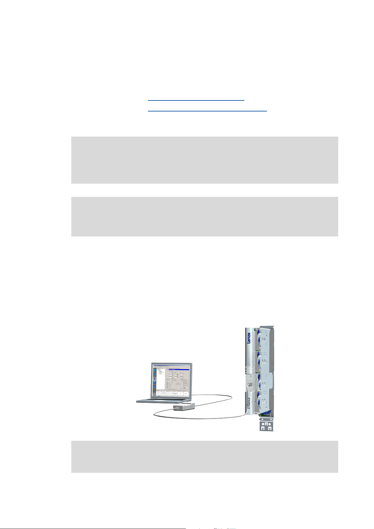
2.2.1 Going online via diagnostic adapter
For initial commissioning of the controller you can for instance use the diagnostic adapter offered
by Lenze:
Note!
Please observe the documentation for the diagnostic adapter!
Lenze · 9400 Servo PLC· Reference manual · DMS 4.0 EN · 11/2013 · TD05/06 21
Page 22
2Introduction
2.2 Communicating with the controller
_ _ _ _ _ _ _ _ _ _ _ _ _ _ _ _ _ _ _ _ _ _ _ _ _ _ _ _ _ _ _ _ _ _ _ _ _ _ _ _ _ _ _ _ _ _ _ _ _ _ _ _ _ _ _ _ _ _ _ _ _ _ _ _
Preconditions:
• The diagnostic adapter is connected to the controller at the diagnostic interface X6 and to the
PC at a free USB port.
• The driver required for the diagnostic adapter is installed.
• The control electronics of the controller is supplied with 24 V low voltage via plug X2.
How to build up an online connection via the diagnostic adapter:
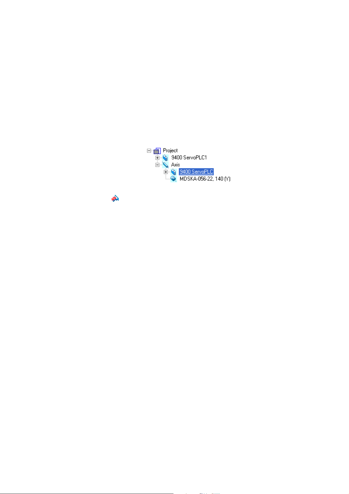
1. Select the controller to which you want to build up an online connection in the Project view
of the »Engineer«:
2. Click the icon.
If the changes you have made on the project have not been accepted yet, first a query on
whether an update is to be carried out is effected.
If an update is to be carried out:
•Click on Yes to open the Update project dialog box.
•Press the Create button in the Update project dialog box to update the changed project
elements.
• After the update a note is shown, saying whether the update was carried out
successfully.
22
Lenze · 9400 Servo PLC· Reference manual · DMS 4.0 EN · 11/2013 · TD05/06
Page 23
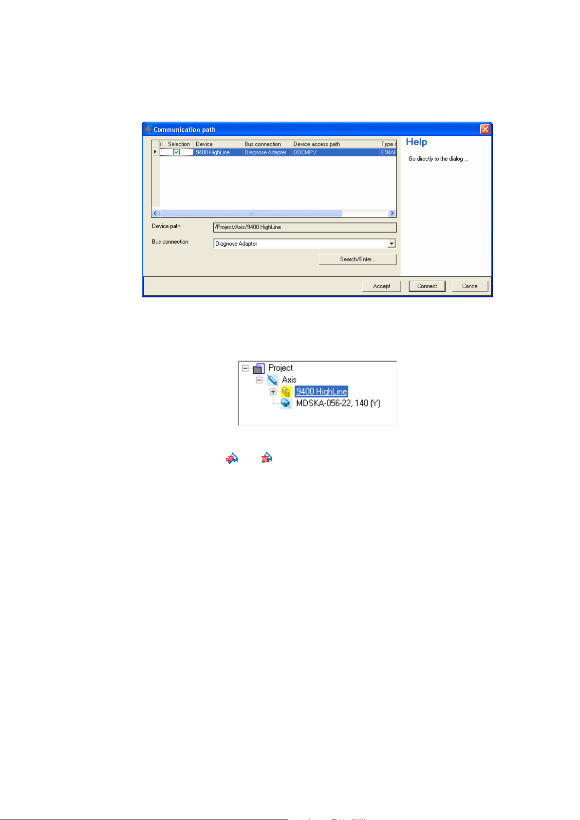
2Introduction
2.2 Communicating with the controller
_ _ _ _ _ _ _ _ _ _ _ _ _ _ _ _ _ _ _ _ _ _ _ _ _ _ _ _ _ _ _ _ _ _ _ _ _ _ _ _ _ _ _ _ _ _ _ _ _ _ _ _ _ _ _ _ _ _ _ _ _ _ _ _
If no communication path was configured yet for the controller selected, the
Communication path dialog box is shown after the update has been carried out:
• The "Diagnostic adapter" bus connection is already preset.
3. Click on Connect.
• The dialog box is closed and the online connection with the controller is built up.
•In the Project view a yellow icon indicates the online connection with the controller:
Now you can use the icons and to easily build up and end a connection with the controller.
The communication settings are only required when communication with a controller is built up for
the first time.
• If you want to change the configured communication path, select the command Online Set
communication path and go online to open the Communication path dialog box and change the
settings.
• When an online connection has been established, the »Engineer« displays the current
parameter settings of the controller with a yellow background colour.
Lenze · 9400 Servo PLC· Reference manual · DMS 4.0 EN · 11/2013 · TD05/06 23
Page 24
2Introduction
2.2 Communicating with the controller
_ _ _ _ _ _ _ _ _ _ _ _ _ _ _ _ _ _ _ _ _ _ _ _ _ _ _ _ _ _ _ _ _ _ _ _ _ _ _ _ _ _ _ _ _ _ _ _ _ _ _ _ _ _ _ _ _ _ _ _ _ _ _ _
2.2.2 Going online via system bus (CAN on board)
As an alternative to the diagnostic adapter, you can use the integrated system bus interface (CAN on
board, terminal X1) of the controller for communication.
• Lenze offers the following communication accessories for connection to the PC:
Communication accessories PC interface
PC system bus adapter 2173
incl. connection cable and voltage supply adapter
• for DIN keyboard connection (EMF2173IB)
• for PS/2 keyboard connection (EMF2173IBV002)
• for PS/2 keyboard connection with electrical isolation (EMF2173IBV003)
PC system bus adapter 2177
incl. connection cable (EMF2177IB)
Parallel interface
(LPT port)
USB
(Universal Serial Bus)
Note!
• For detailed information about the PC system bus adapter, please see the "CAN
Communication Manual".
• Please observe the documentation for the PC system bus adapter!
• The online connection is established as described in the previous chapter "Going
online via diagnostic adapter", only that this time the entry "CAN system bus" is to be
selected in the Bus connection list field of the Communication path dialog box.
( 22)
2.2.3 Use of other communication interfaces
The controller can be extended by further communication interfaces, if required, e.g. Ethernet,
ETHERNET Powerlink, or PROFIBUS.
• For this the controller is provided with the module slots MXI1 and MXI2 for accepting
communication modules.
• Detailed information on this subject can be found in the Hardware Manual and Communication
Manual for the corresponding communication system.
24
Lenze · 9400 Servo PLC· Reference manual · DMS 4.0 EN · 11/2013 · TD05/06
Page 25
2Introduction
2.3 Signal types & scaling
_ _ _ _ _ _ _ _ _ _ _ _ _ _ _ _ _ _ _ _ _ _ _ _ _ _ _ _ _ _ _ _ _ _ _ _ _ _ _ _ _ _ _ _ _ _ _ _ _ _ _ _ _ _ _ _ _ _ _ _ _ _ _ _
2.3 Signal types & scaling
It is very helpful for the parameterisation & configuration of the controller to know the signal types
and their scaling listed below, which serve to process physical quantities (e.g. a speed or position)
within the function block interconnection.
Signal type (data type)
Scaled (INT) 16 bits ± 199.99 % 2 _a
Scaled (DINT) 32 bits ± 200.00 % 2 _n
Speed (INT) / 16 bits ± 30000.0 rpm 1 _v
Speed (DINT) 32 bits ± 480000.0 rpm 1 _s
Position/angle (DINT) / 32 bits -2
Digital (BOOL) 1 bit 0 ≡ FALSE; 1 ≡ TRUE 0
Acceleration (DINT) 32 bits ± 7.69 * 10
Time 28 bits 0 ... 268435.456 s 3
Other (BYTE) 8 bits 0 ... 255 0
Other (WORD) 16 bits 0 ... 65535 0
Other (DWORD) 32 bits 0 ... 4294967295 0
Other (INT) 16 bits -32768 ... 32767 0
Other (DINT) 32 bits -2147483648 ... 2147483647 0
Connection
symbol
Resolution
Value range (external)
31
... 231-1 increments 3 _p
9
rpm/s 3 _x
Decimal positions/
signal type suffix
in the identifier
Scaling of physical units
Signal type
Scaled (INT) 16 bits 100 % ≡ 2
Scaled (DINT) 32 bits 100 % ≡ 2
Speed (INT) / 16 bits 15000 rpm ≡ 2
Speed (DINT) 32 bits 15000 rpm ≡ 2
Position/angle (DINT) / 32 bits 1 encoder revolution ≡ 2
Acceleration (DINT) 32 bits 15000000 rpm/s ≡ 2
Connection
symbol
Resolution
Scaling
External value ≡ internal value
14
≡ 16384
30
≡ 1073741824
14
≡ 16384
26
≡ 67108864
16
increments
22
≡ 4194304
Lenze · 9400 Servo PLC· Reference manual · DMS 4.0 EN · 11/2013 · TD05/06 25
Page 26

3 Commissioning
_ _ _ _ _ _ _ _ _ _ _ _ _ _ _ _ _ _ _ _ _ _ _ _ _ _ _ _ _ _ _ _ _ _ _ _ _ _ _ _ _ _ _ _ _ _ _ _ _ _ _ _ _ _ _ _ _ _ _ _ _ _ _ _
3 Commissioning
This documentation contains detailed information on parameter setting and configuration of the
controller. Sequential reading is not required.
In order to obtain the information relevant for initial commissioning, this chapter describes
different commissioning scenarios which can also be used as a guide through this manual:
A. Initial commissioning
• Target: Adapting the controller to the electromechanics and the control system.
B. Standard set-up
• Target: Taking over the application and parameter set of an already preconfigured "Engineer"
project into several controllers.
( 29)
( 30)
C. Controller replacement
• Target: Replacing a controller which has failed in a running system by a replacement device
using the "old" memory module.
D. Motor replacement
• Target: Replacing a motor which has failed in a running system.
( 31)
( 31)
26 Lenze · 9400 Servo PLC· Reference manual · DMS 4.0 EN · 11/2013 · TD05/06
Page 27
3 Commissioning
3.1 General information
_ _ _ _ _ _ _ _ _ _ _ _ _ _ _ _ _ _ _ _ _ _ _ _ _ _ _ _ _ _ _ _ _ _ _ _ _ _ _ _ _ _ _ _ _ _ _ _ _ _ _ _ _ _ _ _ _ _ _ _ _ _ _ _
3.1 General information
Note!
Some parameters of the controller have a setting range depending on the device type.
If parameterisation is carried out offline or if the memory module is exchanged between
different 9400 ServoPLC device types, always check the settings of the parameters listed
in the following table and adapt them, if required, to prevent a parameter error after the
parameter set download or module change!
Parameter Info Lenze setting
C00018
C00022
C00173
C00174
Switching frequency 8 kHz variable
Maximum current
Accepting/adapting plant parameters
Mains voltage and undervoltage threshold (LU)
Machine parameters
( 80)
( 172)
0.00 A
400/415 V, LU = 285 V
Tip!
The rated data of the different device types can be found in the Hardware Manual in the
"Rated data" chapter.
Term definition of "Plant parameters"
The term "plant parameters" which is frequently used in the following chapters summarises all
parameters which result from the combination of motor and load. They characterise the transfer
behaviour of the entire controlled system including the desired monitoring functions. The plant
parameters depend on the application in which the controller and motor are used.
Lenze · 9400 Servo PLC· Reference manual · DMS 4.0 EN · 11/2013 · TD05/06 27
Page 28

3 Commissioning
3.2 Notes on commissioning using the keypad
_ _ _ _ _ _ _ _ _ _ _ _ _ _ _ _ _ _ _ _ _ _ _ _ _ _ _ _ _ _ _ _ _ _ _ _ _ _ _ _ _ _ _ _ _ _ _ _ _ _ _ _ _ _ _ _ _ _ _ _ _ _ _ _
3.2 Notes on commissioning using the keypad
For a motor with an electronic nameplate (ENP)
• A display of the plant parameters offered by ENP via keypad is not provided. The plant
parameters must be edited and optimised individually.
• To avoid that the motor starts unintentionally without adjusting the plant parameters, the
maximum current in the Lenze setting is set to "0 A" in C00022
• After setting the plant parameters, they have to be saved on the memory module of the
controller with mains failure protection, just as the motor data that have been read out from
the ENP (C00002
For a motor without an electronic nameplate (ENP)
• The motor data and plant parameters must be edited and set individually.
• To avoid that the motor starts unintentionally without adjusting the plant parameters, the
maximum current is set to "0 A" in C00022
• After setting the motor data and plant parameters, they have to be saved on the memory
module of the controller with mains failure protection (C00002
= "11: Save start parameters").
by the factory.
.
= "11: Save start parameters").
Commissioning of the application
• The application must already be stored on the memory module of the controller. Otherwise
commissioning by only using the keypad is not possible.
• All application parameters which deviate from the factory adjustment have to be edited
individually. For this the project planner has to provide a corresponding list to the commissioner
(including the motor and plant data).
• In the case of a standard set-up, a pole position identification may have to be carried out for
synchronous motors of a third party manufacturer or Lenze synchronous motors with a
Stegmann absolute value encoder.
• After setting the parameters, they have to be saved on the memory module of the controller
with mains failure protection (C00002
= "11: Save start parameters").
28
Lenze · 9400 Servo PLC· Reference manual · DMS 4.0 EN · 11/2013 · TD05/06
Page 29
3 Commissioning
3.3 Initial commissioning
_ _ _ _ _ _ _ _ _ _ _ _ _ _ _ _ _ _ _ _ _ _ _ _ _ _ _ _ _ _ _ _ _ _ _ _ _ _ _ _ _ _ _ _ _ _ _ _ _ _ _ _ _ _ _ _ _ _ _ _ _ _ _ _
3.3 Initial commissioning
Worksteps
Parameterising motor control:
1. Read out the motor data of the controller or select them via the »Engineer« motor catalogue.
• If the motor connected to the controller is provided with an electronic nameplate (ENP), all motor
data are automatically read out from the ENP and a selection in the motor catalogue is not required.
Reading out motor data from the controller
• If a motor without ENP or a motor by a third-party manufacturer is used, the selection is carried out
via the »Engineer« motor catalogue. Selecting a motor from the motor catalogue in the »Engineer«
( 166)
2. Select motor control
• Servo control is preset for the synchronous motor.
3. Adjusting motor and controller to each other
4. Carry out settings for selected motor control.
• For this see description for the corresponding motor control:
• Servo control (SC)
• Sensorless vector control (SLVC) ()
• V/f control (VFCplus)
• V/f control (VFCplus)
Optimise control mode:
7. Optimise control mode of the selected motor control.
• By means of traversing profile from the application and oscilloscope.
• For this see description for the corresponding motor control:
• Servo control (SC)
• Sensorless vector control (SLVC) ()
• V/f control (VFCplus)
• V/f control (VFCplus)
Save project and parameter set:
8. Execute device command C00002
9. Save »Engineer« project.
. ( 169)
()
()
()
()
= "11: Save start parameters".
( 165)
( 171)
More (optional) worksteps
Worksteps
Establish network:
1. Insert network and machine application into the »Engineer« project.
2. Interconnect port blocks reasonably to each other within the machine application.
3. Configure network (set addresses, baud rate, and process data channels in a reasonable manner).
4. Establish communication with the control system.
5. Establish communication with other drive components (e.g. HMIs, I/O extensions and other controllers).
Lenze · 9400 Servo PLC· Reference manual · DMS 4.0 EN · 11/2013 · TD05/06 29
Page 30
3 Commissioning
3.4 Standard set-up
_ _ _ _ _ _ _ _ _ _ _ _ _ _ _ _ _ _ _ _ _ _ _ _ _ _ _ _ _ _ _ _ _ _ _ _ _ _ _ _ _ _ _ _ _ _ _ _ _ _ _ _ _ _ _ _ _ _ _ _ _ _ _ _
Worksteps
Check & optimise application/DC-bus operation:
1. Traverse axis in manual operation.
•See chap. Basic drive functions
2. Check area boundaries (path, speed, torque).
3. Traverse axis in automatic operation with set-up speed, possibly together with coupled axes.
4. Check coupling with other movements (master/slave axes, tools, …).
5. Optimisation of the process at higher speeds.
6. Recording of typical signal characteristics using the oscilloscope function for the documentation.
•See chapter Oscilloscope
Save & archive project and parameter set:
1. Execute device command C00002
2. Save »Engineer« project.
3. Deposit a backup copy of the »Engineer« project, e.g. on CD ROM, in the control cabinet.
Manual jog ( 435)
( 611)
= "11: Save start parameters".
3.4 Standard set-up
Worksteps
Transfer application and parameter set to the controller:
1. Transfer the application preconfigured in »Engineer« and the corresponding parameter set to the
For a motor with an electronic nameplate (ENP):
For a motor without an electronic nameplate (ENP):
2. Execute device command C00002
3. Restart controller with connected motor to read out the motor data from the electronic nameplate
4. Execute device command C00002
memory module of the controller.
= "11: Save start parameters".
(ENP).
• Either by switching off/switching on again the voltage supply or by means of device command
•See chap. Motor interface
Note:
The motor is operated with the motor data and plant parameters identified during initial
commissioning. Adjusting motor and controller to each other
= "11000: Restart controller".
C00002
Reading out motor data from the controller ( 165)
= "11: Save start parameters".
( 171)
30
Lenze · 9400 Servo PLC· Reference manual · DMS 4.0 EN · 11/2013 · TD05/06
Page 31

3 Commissioning
3.5 Controller replacement
_ _ _ _ _ _ _ _ _ _ _ _ _ _ _ _ _ _ _ _ _ _ _ _ _ _ _ _ _ _ _ _ _ _ _ _ _ _ _ _ _ _ _ _ _ _ _ _ _ _ _ _ _ _ _ _ _ _ _ _ _ _ _ _
3.5 Controller replacement
Scenario: The controller has failed in a running system.
Note!
For the procedure described in the following it is assumed that the memory module and
possibly available extension modules in the controller, as well as the motor are not
affected by the failure and that all parameters have been saved with mains failure
protection.
Worksteps
Replacement of the controller:
1. Replace controller.
See Mounting Instructions for the controller!
2. Insert the memory module of the failed controller into the replacement device.
3. If further extension modules are plugged into the failed controller, they must be inserted into the
replacement device as well.
Further steps are not required since all data required are on the memory module.
3.6 Motor replacement
Scenario: The motor has failed in a running system.
Note!
For the procedure described in the following it is assumed that the controller is not
affected by the failure.
Worksteps
Replacement of the motor:
1. Replace the motor.
See Mounting Instructions for the controller!
Note:
The motor connection on the controller is accessible without having to remove the standard device
from the installation backplane.
For a motor with an electronic nameplate (ENP):
2. Restart controller with connected motor to read out the motor data from the electronic nameplate.
• Either by switching off/switching on again the voltage supply or by means of device command
C00002
• See chap. Motor interface
3. Execute device command C00002
For a motor without an electronic nameplate (ENP):
Note:
The motor is operated with the motor data and plant data from the memory module.
= "11000: Restart controller".
Reading out motor data from the controller ( 165)
= "11: Save start parameters".
Lenze · 9400 Servo PLC· Reference manual · DMS 4.0 EN · 11/2013 · TD05/06 31
Page 32

4 PLC functionality
_ _ _ _ _ _ _ _ _ _ _ _ _ _ _ _ _ _ _ _ _ _ _ _ _ _ _ _ _ _ _ _ _ _ _ _ _ _ _ _ _ _ _ _ _ _ _ _ _ _ _ _ _ _ _ _ _ _ _ _ _ _ _ _
4 PLC functionality
This chapter provides information on how to prepare, execute and complete a PLC programming.
The description focuses on the »PLC Designer« engineering software which serves to implement the
tasks mentioned.
Moreover, the software provides more opportunities than can be described here. More information
can be found in the associated online help of »PCL Designer«.
See also: Technical data
Task and timing frame
User task
Runtime measurement
Data consistency
Storage capacities and memory modules
Known function restrictions of the controller
32 Lenze · 9400 Servo PLC· Reference manual · DMS 4.0 EN · 11/2013 · TD05/06
Page 33

4 PLC functionality
4.1 Setting the controller in »Engineer«
_ _ _ _ _ _ _ _ _ _ _ _ _ _ _ _ _ _ _ _ _ _ _ _ _ _ _ _ _ _ _ _ _ _ _ _ _ _ _ _ _ _ _ _ _ _ _ _ _ _ _ _ _ _ _ _ _ _ _ _ _ _ _ _
4.1 Setting the controller in »Engineer«
System requirements
The installation of »Engineer« requires a PC with the following system requirements:
• processor with 1.4 GHz or higher
• A main memory of at least 512 MB and 650 MB of free hard disk space
•Microsoft
Required software
The following engineering software is required for programming, parameterising, configuring and
diagnosing the »9400 ServoPLC«
• »PLC Designer« for programming a drive application according to IEC 61131-3
Thus, separate system blocks are available, which, if required, can be integrated in the control
configuration, and which then can be accessed from the IEC 61131-3 program via the
corresponding system variables.
• »Engineer« HighLevel for parameterising, configuring and diagnosing Lenze controllers.
Windows 2000 (service pack 2) or Windows XP
Tip!
The full version of the L-force engineering software »Engineer« HighLevel can be obtained
as single user, multiple user, company, or buyout license.
You obtain the »Engineer« engineering software by
• contacting the Lenze employee responsible for your region or
• placing the order via the following internet address:
http://www.Lenze.com
The »PLC Designer« engineering software and updates of »Engineer« and »PLC Designer«
can be downloaded for free in the download area "Services & Downloads".
An online help is also available for »PLC Designer«. It can be accessed by pressing the <F1>
button when being in the program. Many of the information that cannot be explained here
in detail, can be found there, e.g. the components described above.
.
Lenze · 9400 Servo PLC· Reference manual · DMS 4.0 EN · 11/2013 · TD05/06 33
Page 34

4 PLC functionality
4.1 Setting the controller in »Engineer«
_ _ _ _ _ _ _ _ _ _ _ _ _ _ _ _ _ _ _ _ _ _ _ _ _ _ _ _ _ _ _ _ _ _ _ _ _ _ _ _ _ _ _ _ _ _ _ _ _ _ _ _ _ _ _ _ _ _ _ _ _ _ _ _
4.1.1 First steps for setting the controller
When pressing the <F1> button, you start the online help of »Engineer«. In addition to the
descriptions of the Lenze controllers, the online help also contains the general
»Engineer«.
The following topics are described here. They are to be processed in the given order as a
precondition for the further descriptions in this manual:
1. Create a new project with controllers of the »9400 ServoPLC« series.
2. Select a memory module MM340 or MM440 for each controller.
3. Select the PLC application applicable for the memory module.
description of
Tip!
Please continue to use the online help as a supplementary description for the following
chapters.
After the actions mentioned above are completed, the Application parameters tab of the controller
appears in »Engineer«.
Usually, no PLC project has been assigned to the newly
respective entry, see arrow:
created device. Thus, the tab contains a
Instructions of how to export a newly created PCL application can be found in the section
Assignment of a PLC project for a newly created ServoPLC
( 36)
34
Lenze · 9400 Servo PLC· Reference manual · DMS 4.0 EN · 11/2013 · TD05/06
Page 35

4 PLC functionality
4.1 Setting the controller in »Engineer«
_ _ _ _ _ _ _ _ _ _ _ _ _ _ _ _ _ _ _ _ _ _ _ _ _ _ _ _ _ _ _ _ _ _ _ _ _ _ _ _ _ _ _ _ _ _ _ _ _ _ _ _ _ _ _ _ _ _ _ _ _ _ _ _
4.1.2 Export and import of PLC applications
The exchange of PLC applications between »Engineer« and »PLC Designer« takes place by means of
the Export PLC Application and Import PLC Application buttons:
• The PLC project contained in »Engineer« is exported to a separate directory by means of the
Export PLC Application button.
• Development of the PLC application in the exported PLC project directory is carried out with
»PLC Designer«.
• After these actions are completed, the application must be re-imported into »Engineer«. This is
done by pressing the Import PLC application button.
[4-1] Exchange of the PLC application between »Engineer« and »PLC Designer«
Tip!
If you want to use a PLC project that is already available, please read the section
Select an already existing project
How to import a program from »PLC Designer« into »Engineer« is described in section
Import in the »Engineer« project
( 38)
( 65)
Lenze · 9400 Servo PLC· Reference manual · DMS 4.0 EN · 11/2013 · TD05/06 35
Page 36

4 PLC functionality
4.1 Setting the controller in »Engineer«
_ _ _ _ _ _ _ _ _ _ _ _ _ _ _ _ _ _ _ _ _ _ _ _ _ _ _ _ _ _ _ _ _ _ _ _ _ _ _ _ _ _ _ _ _ _ _ _ _ _ _ _ _ _ _ _ _ _ _ _ _ _ _ _
Assignment of a PLC project for a newly created ServoPLC
If the PLC project has not yet been assigned, please observe the following instructions.
How to export a PLC application from the »Engineer« project
1. Click on the Export PLC application button.
• An empty or not yet available directory must be indicated for the export. For this
purpose, »Engineer« proposes a directory name which contains the ending "_PLC" in
addition to the project name:
• Contrary to the proposal of »Engineer« the directory with the project file can also be
exported into another directory.
• Neither the directory nor files may be write-protected.
2. Click the "Complete" button.
• The PLC application contained in the »Engineer« project is exported in the directory that
is named before (in the example below: "Projekt_PLC").
In this directory, a subdirectory is created for the component (»9400 ServoPLC«) of the
project which has the name of the component in the project (e.g. "9400_ServoPLC-1").
• Each of the component directories contains a file with the file type PRO, PRG, CHK and
ECI:
36
Lenze · 9400 Servo PLC· Reference manual · DMS 4.0 EN · 11/2013 · TD05/06
Page 37

4 PLC functionality
4.1 Setting the controller in »Engineer«
_ _ _ _ _ _ _ _ _ _ _ _ _ _ _ _ _ _ _ _ _ _ _ _ _ _ _ _ _ _ _ _ _ _ _ _ _ _ _ _ _ _ _ _ _ _ _ _ _ _ _ _ _ _ _ _ _ _ _ _ _ _ _ _
3. Repeat export function for further controllers (components) with PLC functionality
• Independent of the project structure in »Engineer«, all exported component directories
are saved in the same directory.
Please note that, as an exception to the Lenze setting, the directory structure of the project
can be stored differently for each axis.
The directory path of the PLC project is saved relatively to the directory of the »Engineer«
project in the »Engineer« project. The PLC project will only be saved with an absolute path
indication if the PLC project is located on a different drive than the »Engineer« project. This,
among other things, makes the transfer of the project more difficult.
The "FileSave under" menu command only serves to save the »Engineer« project in a
different directory. The PLC projects and the assignment to the PLC projects in the
»Engineer« project remain untouched.
Lenze · 9400 Servo PLC· Reference manual · DMS 4.0 EN · 11/2013 · TD05/06 37
Page 38

4 PLC functionality
4.1 Setting the controller in »Engineer«
_ _ _ _ _ _ _ _ _ _ _ _ _ _ _ _ _ _ _ _ _ _ _ _ _ _ _ _ _ _ _ _ _ _ _ _ _ _ _ _ _ _ _ _ _ _ _ _ _ _ _ _ _ _ _ _ _ _ _ _ _ _ _ _
Select an already existing project
1. Click on the ... button.
Select the project file <File name>.PRO of an already existing PLC project.
The example is about the supplied Standard project "PLC_Application.pro"
( 40).
38
Lenze · 9400 Servo PLC· Reference manual · DMS 4.0 EN · 11/2013 · TD05/06
Page 39

4 PLC functionality
4.2 Preparations for creating a PLC program
_ _ _ _ _ _ _ _ _ _ _ _ _ _ _ _ _ _ _ _ _ _ _ _ _ _ _ _ _ _ _ _ _ _ _ _ _ _ _ _ _ _ _ _ _ _ _ _ _ _ _ _ _ _ _ _ _ _ _ _ _ _ _ _
4.2 Preparations for creating a PLC program
Once a project has been assigned or exported to a directory, »PLC Designer« can be started with this
project.
Tip!
How to terminate the project is described in section
Completing the PLC project
4.2.1 Starting »PLC Designer« from »Engineer«
»PLC Designer« is started from the Application parameters tab of »Engineer«:
•Click the Start »PLC Designer« button:
( 64)
»PLC Designer« starts and loads the project assigned.
In this case it is the Standard project "PLC_Application.pro"
Version of »PLC Designer«
The »Engineer« project stores the version of »PLC Designer« with which the project was edited last.
»Engineer« suggests this version for editing the PLC project.
If this version of »PLC Designer« is not installed or is a newly created project, the latest version is
suggested.
( 40)
Lenze · 9400 Servo PLC· Reference manual · DMS 4.0 EN · 11/2013 · TD05/06 39
Page 40

4 PLC functionality
4.2 Preparations for creating a PLC program
_ _ _ _ _ _ _ _ _ _ _ _ _ _ _ _ _ _ _ _ _ _ _ _ _ _ _ _ _ _ _ _ _ _ _ _ _ _ _ _ _ _ _ _ _ _ _ _ _ _ _ _ _ _ _ _ _ _ _ _ _ _ _ _
4.2.1.1 Standard project "PLC_Application.pro"
»Engineer« supplies a standard project for the controller. This standard project should generally
provide the basis of each PLC project.
The main window of »PLC Designer« shows the Object Organizer which is important for the
following descriptions with the Blocks, Data types, Visualisations and Resources:
Tab Blocks
The Blocks tab of the standard project contains
•Application (PRG)
•Idle (PRG)
•User (PRG)
•Visu (PRG)
Tab Data types
The Data types tab of the standard project contains 60 different user data type for ports.
Tab Visualisations
This tab will not be discussed in greater detail within the scope of this manual.
Tab Resources
The Resources tab of the standard project contains
• the tasks Application Task, User Task, Visu Task and Idle Task in the task configurations. The
associated description can be found in the section Configuring tasks
• 60 global variables for accessing the ports in the Ports list
• 60 user codes for mapping the ports in the parameter manager.
• the libraries IecSfc.lib, standard.lib and SysLibCallBack.lib in the library manager
( 43)
Tip!
An online help is also available for »PLC Designer«. It can be accessed by pressing the <F1>
button when being in the program.
Information that cannot be described in detail here in the manual is explained there, e.g.
the components mentioned above.
40
Lenze · 9400 Servo PLC· Reference manual · DMS 4.0 EN · 11/2013 · TD05/06
Page 41

4 PLC functionality
4.2 Preparations for creating a PLC program
_ _ _ _ _ _ _ _ _ _ _ _ _ _ _ _ _ _ _ _ _ _ _ _ _ _ _ _ _ _ _ _ _ _ _ _ _ _ _ _ _ _ _ _ _ _ _ _ _ _ _ _ _ _ _ _ _ _ _ _ _ _ _ _
4.2.2 Setting the communication parameters in »PLC Designer«
Stop!
It is impermissible to establish an online connection to a device via the same bus system
with Engineer and
How to set the communication parameters in »PLC Designer«:
1. Select command OnlineCommunication parameters ....
2. Click the New button
3. Select the required interface
4. Click OK.
»PLC Designer«.
4.2.3 Selecting libraries
When setting the »9400 ServoPLC«, comprehensive libraries are available to support the
implementation of drive tasks.
An overview provides the tables divided according to CoDeSys and Lenze libraries.
Overview of the CoDeSys libraries
• Menu command: WindowLibrary manager
Library name Info
Analyzation.lib FBs for analysing transition terms in case of SFC
CheckBounds Function for monitoring array limits with indirect addressing
CheckDiv Functions for monitoring divisions
CheckPointer Function for monitoring pointer accesses
CheckRange.lib Functions for checking overflows
Iecsfc.lib FB "SFCActionControl" for IEC61131-3 conform processing of the SFC
Standard.lib FBs and functions from IEC61131-3
SysLibCallback.lib SysCallbackRegister and SysCallBackUnregister which serve to activate
SysLibInitLibrary.lib Function for initialising an external library that is provided on the
SysLibSockets.lib This library supports the access on sockets for communicating via TCP/IP and
SysLibTime.lib Representation of the task time evaluation in the task editor of »PLC
SysTaskInfo.lib Used internally for evaluating the task runtimes
defined callback functions for runtime events
development computer as an obj file. Processing is executed synchronously.
UDP.
Designer«. Processing is executed synchronously.
Lenze · 9400 Servo PLC· Reference manual · DMS 4.0 EN · 11/2013 · TD05/06 41
Page 42

4 PLC functionality
4.2 Preparations for creating a PLC program
_ _ _ _ _ _ _ _ _ _ _ _ _ _ _ _ _ _ _ _ _ _ _ _ _ _ _ _ _ _ _ _ _ _ _ _ _ _ _ _ _ _ _ _ _ _ _ _ _ _ _ _ _ _ _ _ _ _ _ _ _ _ _ _
Overview of the Lenze libraries
• Menu command: InsertAdditional library
Note!
It is only permissible to use the function blocks indicated in the column "FB restrictions"
in the following table with an interval time of 1ms, 2ms, 4ms or 8ms.
Library name Info FB restriction
LenzeCamVxxyy.lib FBs for cam functionality all
LenzeCanMsgVxxyy.lib FBs for CAN communication, transmission, and
LenzeCiA402DeviceProfileVxxyy.lib FBs for implementing the CiA402 profile
LenzeDataConversionVxxyy.lib Data and type converters as well as bit operators
LenzeDevice9400Vxxyy.lib FBs for the evaluation of application errors, states,
LenzeElectricalShaftVxxyy.lib FBs for the master value processing L_EsEncoderConv,
LenzeLineDriveVxxyy.lib FBs for the electrical shaft all
LenzePositioningVxxyy.lib FBs for positioning
LenzeServoDriveVxxyy.lib FBs for speed and position selections all
LenzeSysLibFileVxxyy.lib Functions for using file services
LenzeToolboxVxxyy.lib FBs for arithmetic and logic operations, as well as
"xxyy": Software version ( xx = main version, yy = subversion)
reception of CAN telegrams
and writing/reading of codes
filters
L_DevParReadFix,
L_DevParWriteFix,
L_DevReadParDInt,
L_DevWriteParDInt
L_EsClutchPos,
L_EsStretchIntegrate
L_TbDifferentiate,
L_TbIntegrate,
L_TbPIController,
L_TbPT1Filter,
L_TbRateAction
42
Lenze · 9400 Servo PLC· Reference manual · DMS 4.0 EN · 11/2013 · TD05/06
Page 43

4 PLC functionality
4.2 Preparations for creating a PLC program
_ _ _ _ _ _ _ _ _ _ _ _ _ _ _ _ _ _ _ _ _ _ _ _ _ _ _ _ _ _ _ _ _ _ _ _ _ _ _ _ _ _ _ _ _ _ _ _ _ _ _ _ _ _ _ _ _ _ _ _ _ _ _ _
4.2.4 Configuring tasks
In the Resources tab in the Task configuration object, the task features of the four tasks described in
the section Standard project "PLC_Application.pro"
Please make sure that the interval times of the cyclic tasks are limited to the permissible or optional
values.
Task Priority Type Interval time and watchdog time Sensitivity
Application task 1 cyclic T = 1 ms
User task 2 cyclic T = 2 ms
Visu task 7 cyclic Interval time T = 8 ms,
Idle task 8 free-running
*) The value of interval times of cyclic tasks must always be selected as the power of two (e.g. 24=16ms).
( 40) can be checked.
1
optional: 2ms, 4ms or 8ms,
recommended: 1 ms or 2 ms
1
optional: 2ms, 4ms or 8ms *)
1
optional also larger
Tip!
When the checkbox Update unused I/Os (tab Resources Object Target system settings
tab General) is active, a system task with priority 9 is created.
If you have created your own task with priority 9, this will cause the translation error 3570
(error message: "The tasks 'InputUpdateTask' and 'IdleTask' have the same priority 9").
4.2.4.1 Inserting other user tasks
As described in section Standard project "PLC_Application.pro", the Application, User, Visu and Idle
Task exist after creating a new project.
In order to create other user tasks, mark a task and then select the menu command InsertInsert
task.
Lenze · 9400 Servo PLC· Reference manual · DMS 4.0 EN · 11/2013 · TD05/06 43
Page 44

4 PLC functionality
4.2 Preparations for creating a PLC program
_ _ _ _ _ _ _ _ _ _ _ _ _ _ _ _ _ _ _ _ _ _ _ _ _ _ _ _ _ _ _ _ _ _ _ _ _ _ _ _ _ _ _ _ _ _ _ _ _ _ _ _ _ _ _ _ _ _ _ _ _ _ _ _
4.2.4.2 Program call
A task can only call blocks of PRG type (program). Then this program is the main program of this task.
You access the program call as follows:
Tab Resources Object Task configuration tab Program call
Attach program call
A task can be assigned to one or several programs. More program calls are assigned as follows:
1. Open the Task configuration object
2. Select the task you want call a program from
3. Select the menu command InsertAttach program call
Tip!
A further option for attaching a program is to show the context menu by clicking the right
mouse button in the task configuration field (tab Resources) and select the corresponding
menu item.
If the field marked with the arrow has been selected, the input assistance opens which
displays all programs to be attached to the task.
44
Lenze · 9400 Servo PLC· Reference manual · DMS 4.0 EN · 11/2013 · TD05/06
Page 45

4 PLC functionality
4.2 Preparations for creating a PLC program
_ _ _ _ _ _ _ _ _ _ _ _ _ _ _ _ _ _ _ _ _ _ _ _ _ _ _ _ _ _ _ _ _ _ _ _ _ _ _ _ _ _ _ _ _ _ _ _ _ _ _ _ _ _ _ _ _ _ _ _ _ _ _ _
4.2.4.3 Configuring system events
System events as for example stopping of the PLC processing can result in a block being called and
processed once.
The Task configuration object serves to define which block is to be called at which system event. It
is not required that a block must be defined for each system event.
Tip!
Use the system events function to specify the exceptional behaviour of the "9400
ServoPLC", e.g. in the case of TaskOverrun.
Example: You can create a block for the system event "TaskOverrun" as follows
1. Go to the Task configuration and open the System events
2. Activate the checkmark for the PLC_TaskOverrun system event.
3. Enter the block name to be called in the called POU column, e.g. PLC_Exception.
• If the block does already exist, select it by means of the input assistance <F2>.
• Otherwise, you can create the block via the Create POU PLC button.
The new block can be found on the POU with the name PLC_Exception (FUN).
Note!
Only blocks of the type "program" can be selected with the input assistance whereas
»PLC Designer« creates a block of the type "function" when the button is clicked.
Lenze recommends using blocks of the type "program" for a system event. Otherwise, a
CRC error can occur in the »9400 ServoPLC«, for example, after downloading of the
project when the L_CanInit block is called from the LenzeCanMsg.lib library.
Lenze · 9400 Servo PLC· Reference manual · DMS 4.0 EN · 11/2013 · TD05/06 45
Page 46

4 PLC functionality
4.2 Preparations for creating a PLC program
_ _ _ _ _ _ _ _ _ _ _ _ _ _ _ _ _ _ _ _ _ _ _ _ _ _ _ _ _ _ _ _ _ _ _ _ _ _ _ _ _ _ _ _ _ _ _ _ _ _ _ _ _ _ _ _ _ _ _ _ _ _ _ _
List of the system events
• Execution of a maximum of 1,000 instructions as a result of a system event is permissible.
• POUs (= program organisation unit) which are called by system events are not monitored
according to runtimes by a "watchdog" compared to tasks.
System event The called POU starts, ...
PLC_AfterReset after the PLC has been reset.
PLC_BeforeReset before the PLC is reset.
PLC_DebugLoop Not supported
PLC_FQSPState when quick stop by trouble has been activated.
PLC_MessageState when a message has been activated.
PLC_OnboardCANError when a system bus error occurs (e.g. Bus-Off).
PLC_Start when the PLC is started.
PLC_Stop when the PLC is stopped.
PLC_TaskOverrun when a task has overflown.
PLC_TripState when trouble has been activated.
PLC_WarningState when a warning has been activated.
4.2.5 Inserting more user POUs
Four POUs have already been created in the POUs
Standard project "PLC_Application.pro"
In order to insert more POUs, please select the menu command ProjectObjectInsert.
The New POU opens where you can define the type, name and language you want to use to program
the POU:
( 40).
46
Lenze · 9400 Servo PLC· Reference manual · DMS 4.0 EN · 11/2013 · TD05/06
Page 47

4 PLC functionality
4.3 Programming notes
_ _ _ _ _ _ _ _ _ _ _ _ _ _ _ _ _ _ _ _ _ _ _ _ _ _ _ _ _ _ _ _ _ _ _ _ _ _ _ _ _ _ _ _ _ _ _ _ _ _ _ _ _ _ _ _ _ _ _ _ _ _ _ _
4.3 Programming notes
Note!
Up to and including version 02.xx.xx, remanent variables support RETAIN and PERSISENT
and RETAIN PERSISTENT are not
From version 03.00.00, PERSISTENT and PERSISTENT RETAIN are also supported.
• If a persistent variable is linked to a user-defined write/read code
overwritten as follows after the application has been downloaded:
• When the application is downloaded with the »L-force Engineer«, the parameter
set is also loaded into the »9400 ServoPLC«. Thus, the value of this persistent
variable is overwritten by the download depending on the downloaded parameter
value.
• When the application is downloaded with the »PLC Designer«, the user-defined
codes are set to their initial value. Thus, the value of this persistent variable is
overwritten by the download depending on the initial value of the parameter.
• If a persistent variable is linked to a user-defined read code
after the application has been downloaded.
• The size of the persistent variable memory is limited to 2 kbytes. During the
compilation, an error message is output if this value is exceeded. Please bear in mind
that permanently available contents as e.g. variable names, module names, and data
types reduce the freely available memory space.
supported.
, the variable will be
, the value is kept even
4.3.1 Update function and scaling function
The update function is used to execute time-consuming calculations - similar to the scaling
functions.
• Scaling functions are always called when the corresponding user code is accessed.
• The update function "listens" to changes that have taken place elsewhere, e.g. changes in the
axis data structure, and executes various calculations again.
Some of the Lenze function blocks have an update function. The update function is not called
automatically by the »9400 ServoPLC«; calling of the function must be programmed.
Lenze function blocks with update function have the following syntax:
• Taskname-FBInstanzname.Update()
• Example: Cam.L_LdVirtualMasterP1.Update();
Tip!
In order to protect the resources, the update function of the function blocks should be
called in an unsolicited task.
Whether a function block has an update function, can be recognised by a corresponding
"Update" entry in the library manager.
Lenze · 9400 Servo PLC· Reference manual · DMS 4.0 EN · 11/2013 · TD05/06 47
Page 48

4 PLC functionality
4.3 Programming notes
_ _ _ _ _ _ _ _ _ _ _ _ _ _ _ _ _ _ _ _ _ _ _ _ _ _ _ _ _ _ _ _ _ _ _ _ _ _ _ _ _ _ _ _ _ _ _ _ _ _ _ _ _ _ _ _ _ _ _ _ _ _ _ _
Overview of the function blocks with update function:
Application Function block (FB)
LenzeCam L_CamClutchPos
L_CamSetContDataSDO
L_CamSyncIn
LenzeCiA402DeviceProfile L_CiA402DeviceProfile
LenzeElectricalShaft L_EsClutchPos
L_EsEncoderConv
LenzeLineDrive L_LdClutchAxisP
L_LdClutchV
L_LdConvAxisV
L_LdMPot
L_LdPosCtrlLin
L_LdSyncOperation
L_LdVirtualMasterP
L_LdVirtualMasterV
LenzePositioning L_PosPositionerTable
L_PosProfileTable
LenzeServoDrive L_SdGetPosition
L_SdGetSpeed
L_SdRampGeneratorAny
L_SdSetPosition
L_SdSetSpeed
L_SdSpeedFilter
L_SdSwitchPoint
48
Lenze · 9400 Servo PLC· Reference manual · DMS 4.0 EN · 11/2013 · TD05/06
Page 49

4 PLC functionality
4.3 Programming notes
_ _ _ _ _ _ _ _ _ _ _ _ _ _ _ _ _ _ _ _ _ _ _ _ _ _ _ _ _ _ _ _ _ _ _ _ _ _ _ _ _ _ _ _ _ _ _ _ _ _ _ _ _ _ _ _ _ _ _ _ _ _ _ _
4.3.2 Creating user-defined codes
Memory area
For the 9400 servo inverter, all codes are assigned to different ranges, see table below.
• Within the range C03000 ... C08999, max. 196 kB can be created as user codes in the parameter
manager (register Resources).
• The range C03000 ... C05999 is used for the first instance codes of the Lenze function blocks.
• In order to avoid collisions, user codes must be created as of C06000 (unless they are first
instances).
Assignment Range Contents
Firmware C00000 ... C02999 Codes of the standard device
TA C03000 ... C03099 Basic codes of the technology application
C03100 ... C03499 Multiplexer codes of the technology application
Libraries C03500 ... C03999 Codes of function blocks used
C04000 ...
C05900 ... C05999 LenzeDevice9400
User C06000 ... C08999 Free field for user codes
Reserve C09000 ... C12999
Modules C13000 ... C13999 Extension module/communication module in module slot MXI1
Modules C14000 ... C14999 Extension module/communication module in module slot MXI2
Modules C15000 ... C15999 Safety module in module slot MSI for safety engineering
Reserve C16000 ...
Different kinds of creation
The user-defined codes can be directly created in the parameter manager or via Pragma instruction.
When being compared, both options show the following advantages and disadvantages:
Creation of codes .. Advantage Disadvantage
... in the parameter manager Less memory requirements than the
Pragma instruction
... via Pragma instruction Automatic creation of the parameter
list
Bad clarity due to many columns in
the parameter manager
Complex definition in the declaration
part of the Pragma instruction
Lenze · 9400 Servo PLC· Reference manual · DMS 4.0 EN · 11/2013 · TD05/06 49
Page 50

4 PLC functionality
4.3 Programming notes
_ _ _ _ _ _ _ _ _ _ _ _ _ _ _ _ _ _ _ _ _ _ _ _ _ _ _ _ _ _ _ _ _ _ _ _ _ _ _ _ _ _ _ _ _ _ _ _ _ _ _ _ _ _ _ _ _ _ _ _ _ _ _ _
Procedure for creating user-defined codes
Danger!
The creation of codes that access individual bits of variables is not permissible for the
»9400 ServoPLC«.
1. Import the parameter list of »PLC Designer« to »Engineer« before exiting »Engineer«.
2. Comply with the following order
(see also Completing the PLC project
• Translate PLC project in »PLC Designer«, create boot project and then save
• Import the parameter list from »PLC Designer« to »Engineer«
• Save the project in »Engineer«
3. Creation of the codes with the parameter manager or Pragma instruction. Decide for one of the
two options:
• How to create codes in the parameter manager
• How to create codes with Pragma ( 50)
( 64))
( 50)
How to create codes in the parameter manager
1. Open the parameter manager (Resources tab).
2. Click the menu command InsertList…
3. Choose the Variables type and enter a name. (for parameters on ARRAYs, the instance type
has to be selected).
The parameter list appears in the navigation window of the Parameter Manager.
4. To create a new user code, select the menu command InsertRow.
5. Enter a code number.
User codes from C03000 (0x0BB8) onwards can be used.
How to create codes with Pragma
1. Create the Pragma in the declaration editor of the POU.
The appendix contains a
Sample collection for code creation with Pragma instruction
2. Go to »PLC Designer« and select the menu command ProjectClean all.
3. Select the menu command ProjectRebuild all.
During the rebuild process, »PLC Designer« automatically inserts the new parameter list
into the parameter manager.
If now error messages are generated that refer to errors during the Pragma creation, delete
the new parameter list in the Parameter manager. For this purpose, right-click the Context
menu Delete list.
( 76)
50
Rebuild the PLC project after "cleaning".
Lenze · 9400 Servo PLC· Reference manual · DMS 4.0 EN · 11/2013 · TD05/06
Page 51

4 PLC functionality
4.3 Programming notes
_ _ _ _ _ _ _ _ _ _ _ _ _ _ _ _ _ _ _ _ _ _ _ _ _ _ _ _ _ _ _ _ _ _ _ _ _ _ _ _ _ _ _ _ _ _ _ _ _ _ _ _ _ _ _ _ _ _ _ _ _ _ _ _
4.3.3 Generating application error messages
For generating application error messages, the L_DevApplErr and L_DevApplErrFix function blocks
from the LenzeDevice9400Vxxxx library are available.
The errors are written unambiguously via module ID and error ID. Moreover, an error response can
be defined, see the documentation for function libraries.
For defining an error message for an error, the LT_DevErrorList data type is available in the
LenzeDevice9400Vxxxx library.
Data type LT_DevErrorList
Identifier Data type Information/possible settings
dwModulId DWORD Module ID (980 ... 990) of the error
dwErrorId DWORD Error ID (0 ... 65535) for error message
strErrorMessage STRING(64) Error text
Definition of error messages:
1. Depending on the number of the error messages to be defined, an instance of the data type
LT_DevErrorList must be created.
• a declaration as array is possible
• the data type must be defined as global constant and initialised there,
see example:
VAR_GLOBAL CONSTANT
(* Example for declaration of errors as single structures *)
Error1 : LT_DevErrorList := (dwModulId := 980, dwErrorId:=8001,strErrorMessage:='Error1');
Error2 : LT_DevErrorList := (dwModulId := 980, dwErrorId:= 8002,strErrorMessage:=' Error2');
(* Example for declaration of errors as array *)
ErrorList : ARRAY[1..4] OF LT_DevErrorList :=(dwModulId := 901, dwErrorId:=1,strErrorMessage:='Hallo1'),
(dwModulId := 981, dwErrorId:= 8002,strErrorMessage:=' Error3'),
(dwModulId := 981, dwErrorId:= 8003,strErrorMessage:=' Error4'),
(dwModulId := 981, dwErrorId:= 8004,strErrorMessage:=' Error5');
END_VAR
2. The error messages are incorporated in the software when the PLC application is imported into
»Engineer«.
Note!
• If the declaration of error messages is stored in an export file with the name
"Error_Text_Declaration.exp" in the project directory, the error messages will be read
out of this file during the importing process.
• Before error messages are imported from coded
the error messages in an export file.
PLC projects, it is necessary to place
Tip!
The import into the »Engineer« is described in section "Import in the »Engineer« project
( 65)
Lenze · 9400 Servo PLC· Reference manual · DMS 4.0 EN · 11/2013 · TD05/06 51
".
Page 52

4 PLC functionality
4.4 Use of function blocks
_ _ _ _ _ _ _ _ _ _ _ _ _ _ _ _ _ _ _ _ _ _ _ _ _ _ _ _ _ _ _ _ _ _ _ _ _ _ _ _ _ _ _ _ _ _ _ _ _ _ _ _ _ _ _ _ _ _ _ _ _ _ _ _
4.4 Use of function blocks
When working with function blocks, proceed as follows (irrespective whether the function block has
instance codes or not):
1. Inserting the corresponding library in the library management,
menu command WindowLibrary management
2. Declaring the function block.
Parameterisable function blocks
Some function blocks of the controller libraries also have codes that serve to change certain settings
during operation or display actual values and status information.
In contrast to the 9400 HighLine servo inverter, the codes of these function blocks are not created
automatically but by the user in the PLC project.
Note!
If new library versions are incorporated in the PLC project, the initialisation values of
codes of parameterisable function blocks are reset to the Lenze settings.
If necessary, the codes must be reset in the Parameter Manager.
Tip!
Lenze recommends that no changes be made to the initialisation values of codes of
parameterisable function blocks.
Example for creating codes for function blocks:
1. Insert LenzeServoDriveVxxyy.lib library in the library management
2. Insert L_SdRampGenerator POU in the Application program
3. Carry out configuration:
52
Lenze · 9400 Servo PLC· Reference manual · DMS 4.0 EN · 11/2013 · TD05/06
Page 53

4 PLC functionality
4.4 Use of function blocks
_ _ _ _ _ _ _ _ _ _ _ _ _ _ _ _ _ _ _ _ _ _ _ _ _ _ _ _ _ _ _ _ _ _ _ _ _ _ _ _ _ _ _ _ _ _ _ _ _ _ _ _ _ _ _ _ _ _ _ _ _ _ _ _
How to create the codes for function block instances:
1. Open the Parameter manager in the Resources tab.
2. Use the menu command InsertList to open the dialog window Insert list.
3. Activate the Instance field
4. Enter list names (example: "ramp generator").
After being imported into Engineer, the list name appears as pulldown menu in the "All
parametersIEC 1131 parameter" register.
5. Confirm with OK
6. Go to the Template selection field and enter the name of the L_SdRampGenerator function
block
7. Go to the Base variable and enter the name of the instanced POU using the function key
<F2>. Enter 0 in the base index and subindex fields.
8. Select Apply . The following image appears:
9. Import new codes as described in section "Import in the »Engineer« project
In the All parameters tab, the Ramp generator category is displayed.
". ( 65)
Lenze · 9400 Servo PLC· Reference manual · DMS 4.0 EN · 11/2013 · TD05/06 53
Page 54

4 PLC functionality
CPU
0 0 0 0 0 00
4.5 Use of system blocks
_ _ _ _ _ _ _ _ _ _ _ _ _ _ _ _ _ _ _ _ _ _ _ _ _ _ _ _ _ _ _ _ _ _ _ _ _ _ _ _ _ _ _ _ _ _ _ _ _ _ _ _ _ _ _ _ _ _ _ _ _ _ _ _
4.5 Use of system blocks
Functions used for implementing applications for Lenze controllers are described by means of
function blocks (FBs).
• Functions which can be used in your project as software functions are included in the function
libraries as function blocks or functions.
• Moreover, there are quasi hardware functions which are available as system blocks (SBs) in the
»PLC Designer« control configuration.
Principle
The principle of the system blocks can be explained with the help of a PLC system in a rack: The rack
contains the CPU, digital I/Os, analog I/Os, counter cards, positioning cards etc. as additional cards.
• The CPU can directly access the extension cards and process the resulting information.
• The single extension cards have a permanent address for being addressed.
Additional cards
With the »9400 ServoPLC«, the system blocks comply with these additional cards! Thus, system
blocks are special (hardware) function blocks that are permanently implemented in the runtime
system of the »9400 ServoPLC«.
• SBs can address real hardware.
• SBs are assigned/identified by node numbers.
• The inputs/outputs of the SBs are accessed via system variables or absolute memory addresses.
• Inputs/outputs are always classified from the program's point of view.
• Required SBs must be explicitly implemented into the project via the control configurations of
»PLC Designer«.
54
Lenze · 9400 Servo PLC· Reference manual · DMS 4.0 EN · 11/2013 · TD05/06
Page 55

4 PLC functionality
6%
2XWSXWV
6%328
,QSXWV
2XWSXWV
,QSXWV
4.5 Use of system blocks
_ _ _ _ _ _ _ _ _ _ _ _ _ _ _ _ _ _ _ _ _ _ _ _ _ _ _ _ _ _ _ _ _ _ _ _ _ _ _ _ _ _ _ _ _ _ _ _ _ _ _ _ _ _ _ _ _ _ _ _ _ _ _ _
4.5.1 Access via system variables
When you have implemented a system block into the control configuration of »PLC Designer«, you
can use its system variable in your project.
• In the editors of »PLC Designer«, use the function key <F2> to call the input assistance which,
among other things, lists all available system variables.
• In this chapter, the system variables can be found in the description of the corresponding
system block.
4.5.2 Access via absolute addresses
The inputs and outputs of the system blocks can also be accessed via absolute addresses according
to the IEC 61131-3 standard.
• For inputs, the notation "%IDa.b" applies
(X = data type, a = module number, b = double word address)
• For outputs, the notation "%QDa.b" applies
(X = data type, a = module number, b = double word address)
• Each system variable described in the following chapters comes with the corresponding
address.
4.5.3 Definition of the inputs and outputs
In order to establish a connection of the user program with the hardware, system blocks are
connected to the program organisation unit (POU).
Note!
The inputs and outputs are always classified from the program's point of view!
• Logic SB inputs are hardware outputs of the »9400 ServoPLC«.
• Logic SB outputs are hardware inputs of the »9400 ServoPLC«.
Lenze · 9400 Servo PLC· Reference manual · DMS 4.0 EN · 11/2013 · TD05/06 55
Page 56

4 PLC functionality
LS_DigitalInput
POU
DIGIN_bIn1
DIGIN_bIn2
DIGIN_bIn5
DIGIN_bIn4
DIGIN_bIn3
X5 X4
DIGIN_bIn6
DIGIN_bIn7
DIGIN_bIn8
DIGIN_bCInh
DIGIN_
bStateBusIn
1
0
1
C00114/1...8
C00443/1...8
CONTROL
RFR A1
DI1
A2
DI2
A3
DI3
A4
DI4
DI5
DI6
DI7
DI8
SB
SB
X2
X2
LS_DigitalOutput
DIGOUT_bOut1
DIGOUT_
bStateBusOut
DIGOUT_bOut3
DIGOUT_bOut2
1
0
1
C00118/1...4
DIGOUT_bOut4
DIGOUT_
bUserLED
User
LED
C00444/1...4
CONTROL
DriveInterface
1
Inputs
Outputs
4.5 Use of system blocks
_ _ _ _ _ _ _ _ _ _ _ _ _ _ _ _ _ _ _ _ _ _ _ _ _ _ _ _ _ _ _ _ _ _ _ _ _ _ _ _ _ _ _ _ _ _ _ _ _ _ _ _ _ _ _ _ _ _ _ _ _ _ _ _
Example: System block DIGITAL_IO of the »9400 ServoPLC«
If you want to use the digital input 1 and the digital output 1 of the »9400 ServoPLC«, carry out the
following steps:
1. Implement the DIGITAL_IO system block into the control configuration of the »PLC Designer«.
Implementing system blocks in »PLC Designer«
2. For access to the digital input 1:
• The digital inputs can be found under Inputs_Digital[SLOT]
• Assign the system variable DIGIN_bIn1 to a POU input.
3. For access to the digital output 1:
• The digital outputs can be found under Outputs_Digital[SLOT]
• Assign the system variable DIGOUT_bOut1 to a POU output.
[4-2] Connecting the system block DIGITAL_IO of the »9400 ServoPLC« with a POU
4.5.4 Implementing system blocks in »PLC Designer«
The system blocks are the interface between PLC program and the peripherals of the controller (e.g.
digital inputs and outputs).
In order to access from the PLC program to the system blocks, the system blocks must be inserted
into the control configuration.
Note!
The process image of the system blocks is created by the »9400 ServoPLC« in the task
with the highest priority, irrespective of the interval time set for this task.
In the PLC standard project, the ApplicationTask has the highest priority (priority 1).
Thus, a consistent process image is only available in the ApplicationTask. Therefore, the
system blocks should only be accessed in this task.
56
Lenze · 9400 Servo PLC· Reference manual · DMS 4.0 EN · 11/2013 · TD05/06
Page 57

4 PLC functionality
4.5 Use of system blocks
_ _ _ _ _ _ _ _ _ _ _ _ _ _ _ _ _ _ _ _ _ _ _ _ _ _ _ _ _ _ _ _ _ _ _ _ _ _ _ _ _ _ _ _ _ _ _ _ _ _ _ _ _ _ _ _ _ _ _ _ _ _ _ _
Inserting the system blocks
Tab Resources object Control configuration menu command InsertAppend subelement.
Then, a selection list of the system blocks is displayed. In the control configuration, the inputs and
outputs of each implemented system block are listed with the identifier of the corresponding
system variable, the absolute address, and the data type of the system variable:
System variable Absolute address Data type
[4-3] Example: Control configuration for the »9400 ServoPLC« with implemented system block DIGITAL_IO
Lenze · 9400 Servo PLC· Reference manual · DMS 4.0 EN · 11/2013 · TD05/06 57
Page 58

4 PLC functionality
4.5 Use of system blocks
_ _ _ _ _ _ _ _ _ _ _ _ _ _ _ _ _ _ _ _ _ _ _ _ _ _ _ _ _ _ _ _ _ _ _ _ _ _ _ _ _ _ _ _ _ _ _ _ _ _ _ _ _ _ _ _ _ _ _ _ _ _ _ _
Overview of system blocks
The following table lists the system blocks that you can enter into »PLC Designer« in the control
configuration.
Module number Designation in »PLC Designer« Description
Device interfaces
100, 101, 104, 105 CAN_onBoard System bus interface "CAN on board"
200, 201, 600 ... 604 EXTENSION_BOARDS_SLOT1 Interface MXI1 for fieldbus modules
300, 301, 600 ... 604 EXTENSION_BOARDS_SLOT2 Interface MXI2 for fieldbus modules
11 ... 13 ANALOG_IO Analog inputs
Analog outputs
1 ... 3 DIGITAL_IO Digital inputs
Digital outputs
139 ... 150 TP_TouchProbe Touch probe
Touch-Probe-Motor
Touch-Probe-Load
102 ... 103 SYNC_Synchronisation CAN-synchronisation
404 ... 405 SMI_SafetyModuleInterface Interface to the safety module
Safety engineering
Drive and motor interface
152 ... 154 DI_DriveInterface Drive interface
155 ... 157 MI_MotorInterface Motor interface
Basic drive functions
158 ... 160 BRK_Brake Brake control
161 ... 163 FDB_Feedback Encoder evaluation
164 ... 166 HM_Homing Homing
167 ... 169 LIM_Limiter Limiter
170 ... 172 MAN_ManualJog Manual jog
173 ... 175 POS_Positioner Positioning
176 ... 178 PF_PositionFollower Position follower
179 ... 181 QSP_Quickstop Quick stop
182 ... 184 SF_SpeedFollower Speed follower
185 ... 186 STP_Stop Stop
187 ... 189 TF_TorqueFollower Torque follower
193 ... 195 CAM_CamInterface Cam data management
196, 197 SSI_Encoder SSI encoder
198, 199, 500 MOL_ManualJogOpenLoop Encoderless_manual jog
501 ... 503 PPI_PolePositionIdentification Pole position identification
504, 505 ENC_EncoderX8 Encoder signal at X8
58
Lenze · 9400 Servo PLC· Reference manual · DMS 4.0 EN · 11/2013 · TD05/06
Page 59

4 PLC functionality
4.6 Network communication
_ _ _ _ _ _ _ _ _ _ _ _ _ _ _ _ _ _ _ _ _ _ _ _ _ _ _ _ _ _ _ _ _ _ _ _ _ _ _ _ _ _ _ _ _ _ _ _ _ _ _ _ _ _ _ _ _ _ _ _ _ _ _ _
4.6 Network communication
Communication between the single components of an entire system requires fieldbus system for
process automation. For the common fieldbus systems, Lenze offers a great number of
communication modules in addition to the CAN system bus.
This section contains information on PDO mapping for the CAN (on board) implemented in the
controller and on PDO mapping for the fieldbus systems to be adapted additionally.
See also: Communicating with the controller ( 21)
4.6.1 Network communication with CAN on board
The »9400 ServoPLC« features the following parameterisable process data channels (PDO
channels):
• Max. 4 transmission objects (transmit PDO, TPDO) with 1 ... 8 bytes
• Max. 4 transmission objects (receive PDO, RPDO) with 1 ... 8 bytes
PDO mapping in »Engineer«
The data exchange between the »CAN on board« interface and the PLC program is carried out via
ports. In the Ports tab, 30 input ports and 30 output ports are created.
PDO mapping means the connection of the parameterisable process data channels with the ports
of the controller.
Note!
In contrast to the »9400 HighLine«, in the case of the »9400 ServoPLC« the user cannot
create his own ports. Instead of that, a set of fixed ports is provided under the Ports tab,
via which a port interconnection can be carried out.
Tip!
The general online help of »Engineer« describes PDO mapping in the section entitled Insert
and configure network / Process data objects.
Lenze · 9400 Servo PLC· Reference manual · DMS 4.0 EN · 11/2013 · TD05/06 59
Page 60

4 PLC functionality
4.6 Network communication
_ _ _ _ _ _ _ _ _ _ _ _ _ _ _ _ _ _ _ _ _ _ _ _ _ _ _ _ _ _ _ _ _ _ _ _ _ _ _ _ _ _ _ _ _ _ _ _ _ _ _ _ _ _ _ _ _ _ _ _ _ _ _ _
PDO mapping in »PLC Designer«
The access to the ports and therefore to the CAN data is effected via global variables which are
already declared in the Ports list of the global variables.
Standard project "PLC_Application.pro"
In the PLC logic you can access the global "Port“ variables. The name of the variables is identical to
the port.
Each port variable has an individual data type which is defined in the standard project in the Data
types tab.
The CAN mapping of the ports is effected via codes which are defined in the
AutomationSuite_ObjectDirectory list in the parameter manager.
Note!
Without the "AutomationSuite_ObjectDirectory" parameter list the PDO mapping can no
longer be carried out.
If you have deleted the "AutomationSuite_ObjectDirectory" parameter list, the global
variables "Ports", or the associated data types in your project, you can restore the missing
objects by importing them from a standard PLC application.
60
Lenze · 9400 Servo PLC· Reference manual · DMS 4.0 EN · 11/2013 · TD05/06
Page 61

4 PLC functionality
4.6 Network communication
_ _ _ _ _ _ _ _ _ _ _ _ _ _ _ _ _ _ _ _ _ _ _ _ _ _ _ _ _ _ _ _ _ _ _ _ _ _ _ _ _ _ _ _ _ _ _ _ _ _ _ _ _ _ _ _ _ _ _ _ _ _ _ _
4.6.2 Network communication with fieldbus module
PDO mapping in »Engineer«
The »9400 ServoPLC« is to be extended by the Profibus module in the »Engineer« project.
How to execute PDO mapping in »Engineer«:
1. Highlight the corresponding »9400 ServoPLC« in the project view of »Engineer«
2. Select the menu command InsertDevice module...
3. In the field Extension module for MXI1, select the Profibus module V1.11.
4. Click OK.
5. Complete the process by clicking the Complete button.
6. Highlight the element Profibus (Slot1) in the project view.
7. Enter the station address on the Settings tab.
8. Open the Process data objects tab.
Lenze · 9400 Servo PLC· Reference manual · DMS 4.0 EN · 11/2013 · TD05/06 61
Page 62

4 PLC functionality
4.6 Network communication
_ _ _ _ _ _ _ _ _ _ _ _ _ _ _ _ _ _ _ _ _ _ _ _ _ _ _ _ _ _ _ _ _ _ _ _ _ _ _ _ _ _ _ _ _ _ _ _ _ _ _ _ _ _ _ _ _ _ _ _ _ _ _ _
9. Highlight the PDO_RX0 receive object.
• In this example data are to be received via the Profibus.
10. Click on the Edit PDO button.
11. In the Port selection, select the desired port
•In the Process data object structure: PDO_RX0 dialog box you define the connection
between the process data channel and the port.
12. Click on the » button.
62
13. Click OK.
Lenze · 9400 Servo PLC· Reference manual · DMS 4.0 EN · 11/2013 · TD05/06
Page 63

4 PLC functionality
4.6 Network communication
_ _ _ _ _ _ _ _ _ _ _ _ _ _ _ _ _ _ _ _ _ _ _ _ _ _ _ _ _ _ _ _ _ _ _ _ _ _ _ _ _ _ _ _ _ _ _ _ _ _ _ _ _ _ _ _ _ _ _ _ _ _ _ _
14. Click on the icon to build the project.
PDO mapping in »PLC Designer«
How to execute PDO mapping in »PLC Designer«:
1. Start »PLC Designer«.
2. Just like under CAN, the access to the ports and therefore on the Profibus data is effected
via global variables which are already declared in the Ports list of the global variables in the
standard project. Standard project "PLC_Application.pro"
3. In the PLC logic you can access the global "Port“ variables. The name of the variables is
identical to the port.
Lenze · 9400 Servo PLC· Reference manual · DMS 4.0 EN · 11/2013 · TD05/06 63
Page 64

4 PLC functionality
4.7 Completing the PLC project
_ _ _ _ _ _ _ _ _ _ _ _ _ _ _ _ _ _ _ _ _ _ _ _ _ _ _ _ _ _ _ _ _ _ _ _ _ _ _ _ _ _ _ _ _ _ _ _ _ _ _ _ _ _ _ _ _ _ _ _ _ _ _ _
4.7 Completing the PLC project
Comply with the following procedure after PLC programming has been completed:
1. Compiling a PLC project
2. Generating a boot project ( 64)
3. Saving the PLC project ( 65)
4. Import in the »Engineer« project ( 65)
5. Saving the »Engineer« project ( 66)
6. Project download ( 67)
4.7.1 Compiling a PLC project
For compiling the project, click on the menu command ProjectCompile all. In the message window
the number of errors and warnings, the size of the data and retain data consumed and the code size
used is displayed.
( 64)
4.7.2 Generating a boot project
A boot project can only be downloaded using »Engineer«.
The boot project download loads and starts the compiled PLC project automatically in case of a
restart (e.g. mains switching).
The command "OnlineCreate boot project" is used to create the following files, among others, in
the PLC project directory:
• <projektname>.prg for the boot project
• <projektname>.chk for the checksum of the code.
Note!
• During the download it is not checked whether the binary coded data match the
current project. In order to avoid that a non-current project is loaded into the »9400
ServoPLC« unintentionally, Lenze recommends to also generate a boot project after
every compilation process to always keep the files consistent like this.
• The boot project may not be generated in the online mode of »PLC Designer«.
64
Lenze · 9400 Servo PLC· Reference manual · DMS 4.0 EN · 11/2013 · TD05/06
Page 65

4 PLC functionality
4.7 Completing the PLC project
_ _ _ _ _ _ _ _ _ _ _ _ _ _ _ _ _ _ _ _ _ _ _ _ _ _ _ _ _ _ _ _ _ _ _ _ _ _ _ _ _ _ _ _ _ _ _ _ _ _ _ _ _ _ _ _ _ _ _ _ _ _ _ _
How to generate a boot project:
1. Select OnlineCreate boot project
2. Click on the Yes button.
3. Display of the created files:
4. Click OK.
4.7.3 Saving the PLC project
In order to prevent changes to the PLC project from being lost, they have to be saved via the menu
command FileSave before exiting »PLC Designer«.
4.7.4 Import in the »Engineer« project
The PLC project must be imported in »Engineer« after being completed.
The import causes
• the project directory to be copied with all
• the boot project to be saved in the »Engineer« project
• each user code to be declared in the »Engineer« project.
• user error messages to be imported.
subdirectories to the »Engineer« project directory
Lenze · 9400 Servo PLC· Reference manual · DMS 4.0 EN · 11/2013 · TD05/06 65
Page 66

4 PLC functionality
4.7 Completing the PLC project
_ _ _ _ _ _ _ _ _ _ _ _ _ _ _ _ _ _ _ _ _ _ _ _ _ _ _ _ _ _ _ _ _ _ _ _ _ _ _ _ _ _ _ _ _ _ _ _ _ _ _ _ _ _ _ _ _ _ _ _ _ _ _ _
How to import the new codes in »Engineer«:
1. Click on the Import PLC application button on the Application parameters tab.
• During the import, error messages and warnings appear in the message window.
• If the checkmark next to Show details has been activated, the codes and error messages
imported into the »Engineer« project are shown in the message window as well.
The parameters imported can be viewed in the All parameters tab in the IEC 1131 parameters
category. The IEC 1131 parameters category only appears if user codes have been created in »PLC
Designer«.
Note!
By clicking the Import PLC application button, all data (i.e. files and subdirectories) that
4.7.4.1 Saving the »Engineer« project
The project is saved completely if you
1. save the PLC project using »PLC Designer«
2. save the »Engineer« project using »Engineer«.
is the same directory as the project file (*.PRO) is imported into the Engineer project.
66
Lenze · 9400 Servo PLC· Reference manual · DMS 4.0 EN · 11/2013 · TD05/06
Page 67

4 PLC functionality
4.7 Completing the PLC project
_ _ _ _ _ _ _ _ _ _ _ _ _ _ _ _ _ _ _ _ _ _ _ _ _ _ _ _ _ _ _ _ _ _ _ _ _ _ _ _ _ _ _ _ _ _ _ _ _ _ _ _ _ _ _ _ _ _ _ _ _ _ _ _
4.7.5 Project download
Detailed information on the project download and on "Going online" with »Engineer« can be found
in the »Engineer« online help.
Note!
The download by »PLC Designer« may only be used during the development phase of a
device.
The following must be observed:
• The project is not saved with mains failure protection.
• All user codes are reset to their default values.
How to start the project download using »PLC Designer«
1. Go to »PLC Designer« and select the menu command OnlineCommunication parameter.
2. In the Communication parameters dialog, press the New button.
3. Select a name for the new communication channel.
4. Confirm the dialog with OK.
5. Select communication driver (e.g. diagnostic bus driver).
6. Confirm the dialog with OK.
7. Select project download with the menu command OnlineLog-in.
8. Start download with Yes.
How to restore the parameter values after a project download with »PLC Designer«:
1. Download the complete project with the »Engineer«.
2. Persist the project.
3. Send command C00002 = 301 (archive parameter set 1) to the »9400 ServoPLC«.
• All codes (system and user codes) are saved with mains failure protection on the memory
module.
4. Now you can alter the PLC project with »PLC Designer« and load it into the PLC.
5. Send command C00002 = 201 (activate parameter set 1) to the »9400 ServoPLC« to restore
the parameter set.
• All codes stored are reassigned with the saved values.
• All codes removed from the »PLC Designer« project are discarded.
• All codes that are newly created in the »PLC Designer« project have their initialisation
value.
A cod e that is cha nged with regard to its meaning nevertheless receives the stored value
if
• the value stored is within the value limits entered in the parameter manager of »PLC
Designer«.
• the data size of the code has not changed.
Lenze · 9400 Servo PLC· Reference manual · DMS 4.0 EN · 11/2013 · TD05/06 67
Page 68

4 PLC functionality
4.8 Appendix
_ _ _ _ _ _ _ _ _ _ _ _ _ _ _ _ _ _ _ _ _ _ _ _ _ _ _ _ _ _ _ _ _ _ _ _ _ _ _ _ _ _ _ _ _ _ _ _ _ _ _ _ _ _ _ _ _ _ _ _ _ _ _ _
4.8 Appendix
4.8.1 Technical data
Range Description
Inputs and outputs 2 free Analog inputs
2 free Analog outputs
1 digital input for controller enable (RFR)
8 free digital inputs
4 free digital outputs
Operation set According to IEC 61131-3
Counter/times According to IEC 61131-3, depending on the user memory available
RAM memory
for program code & data
File system (flash memory) Depending on the memory module used:
Retain memory
Available calculating time 350 μs per 1 millisecond
Task types 1 cyclic task
Network variables and mapping 0x6000 ... 0x6FFF: Available range for profile indices acc. to CiA402
Configuring software »Engineer«
Programming software »PLC Designer«, is called from the »Engineer«.
Functions Functions which can be used in your project as software functions are
512 kByte code memory
256 kByte data memory
196 kByte memory for user parameters
MM340: 4 MByte
MM440: 8 MByte
Depending on the memory module used:
MM340: 4992 bytes
MM440: 64 kbytes
8 interval-controlled tasks (interval time 1 ms ... 16 s)
• The task with the highest priority must have an interval time of 1 ms or
2ms.
1 unsolicited task
0xA000 ... 0xAFFF: Available range for network variables acc. to CiA405
• Download, Network and project management
• Programming languages according to IEC 61131-3 (AWL, KOP, FUP, ST,
AS)
• Monitoring & visualisation
included in the function libraries as function blocks or functions.
Moreover, there are quasi hardware functions which are available as system
blocks (SBs) in the »PLC Designer« control configuration. Use of system
blocks ( 54)
(touch-probe capable)
68
Lenze · 9400 Servo PLC· Reference manual · DMS 4.0 EN · 11/2013 · TD05/06
Page 69

4 PLC functionality
V V V V
PV
V V V V
PV
6\VWHP 0& 8VHU3/& 0& 6\VWHP 0& 8VHU3/& 0& 6\VWHP 0&
V V
PV
4.8 Appendix
_ _ _ _ _ _ _ _ _ _ _ _ _ _ _ _ _ _ _ _ _ _ _ _ _ _ _ _ _ _ _ _ _ _ _ _ _ _ _ _ _ _ _ _ _ _ _ _ _ _ _ _ _ _ _ _ _ _ _ _ _ _ _ _
4.8.2 Task and timing frame
The task frame of the system mainly consists of a constant change of system components and user
components.
System = system components
MC = Motion Control basic functions
User PLC = freely programmable PLC part
[4-4] Distribution of the system interval
System components:
• Provision of the setpoint data for the control and actual data of the control
• Maintenance of the communication links on SDO and PDO level
• Processing and evaluation of the device status
• Parameter/services and error management
User components:
• Motion Control basic functions (MC)
• The basic functions enable a more comfortable access for motion control of the drive.
• For the »9400 ServoPLC«, the basic functions in »PLC Designer« are available as separate
system blocks which can be inserted, if required, into the control configuration and which
then can be accessed from the IEC 61131-3 program via the corresponding system variables.
• The basic functions are described in detail in the "Basic drive functions" chapter.
• Creation of the task images for the PLC tasks
• PLC part freely programmable by the user (User PLC).
Lenze · 9400 Servo PLC· Reference manual · DMS 4.0 EN · 11/2013 · TD05/06 69
Page 70

4 PLC functionality
4.8 Appendix
_ _ _ _ _ _ _ _ _ _ _ _ _ _ _ _ _ _ _ _ _ _ _ _ _ _ _ _ _ _ _ _ _ _ _ _ _ _ _ _ _ _ _ _ _ _ _ _ _ _ _ _ _ _ _ _ _ _ _ _ _ _ _ _
4.8.3 User task
9 user tasks can be created. User tasks can be event-controlled, time-controlled or unsolicited. Only
one unsolicited task can be created. The user tasks can interrupt themselves in the form of preemptive multitasking and thus make optimum use of the available computing time.
Note!
The »9400 ServoPLC« only ensures data consistency of the task images for the user task
with the highest priority. For all other tasks, the user is responsible for consistency.
Data consistency
Pre-emptive multi-tasking may cause the task images to start with a delay or being
interrupted by tasks with a higher priority. Example of pre-emptive multitasking
( 71)
Tip!
The tasks are created and configured in the »PLC Designer« via the task configuration that
is located as an object in the Object Organizer in the Resources tab.
( 73)
Priorities
Each task is assigned to a priority (1: highest ..... 9: lowest). The hierarchy determines the
distribution of the available calculating time to the tasks.
• One priority cannot be assigned for several tasks.
• The task with the highest priority must be a cyclic task.
• The unsolicited task must always have the lowest priority.
Distribution of the calculating time
Max. 350 μs of calculating time per millisecond are available for the task with the highest priority,
see illustration [4-4]
share this calculating time according to their priority.
• If the processing time in a task with higher priority takes longer, the free calculating time in the
lower-priority tasks is automatically reduced.
• In »PLC Designer«, an interval time of 1 ms, 2 ms, 4 ms or 8 ms must be set for the task with the
highest priority. After this interval time, the task is followed by processing of the basic motor
control functions.
. The calculating time not required remains for the lower-level tasks which
70
Lenze · 9400 Servo PLC· Reference manual · DMS 4.0 EN · 11/2013 · TD05/06
Page 71

4 PLC functionality
8VHU3/& 8VHU3/& 8VHU3/& 8VHU3/&
PV PV PV PV PV
n
4.8 Appendix
_ _ _ _ _ _ _ _ _ _ _ _ _ _ _ _ _ _ _ _ _ _ _ _ _ _ _ _ _ _ _ _ _ _ _ _ _ _ _ _ _ _ _ _ _ _ _ _ _ _ _ _ _ _ _ _ _ _ _ _ _ _ _ _
Example of pre-emptive multitasking
In the following example, three interval-controlled user tasks share the available 350 μs of
computing time per millisecond.
• The respective task cycle will not be used completely by the tasks so that a small amount of
calculating time remains after the lower-priority task 3.
• In the grey areas, processing in the respective task is frozen since either a higher-priority task,
the system part, or the basic motion control functions are being processed.
Task 1 Task 2 Task 3 Free calculating time
[4-5] Example "pre-emptive multitasking"
User task Priority Task interval
Task 1 1 1 ms
Task 2 2 2 ms
Task 3 3 4 ms
Tip!
The example in illustration [4-5]
total 1400 μs calculating time (4 task cycles * 350 μs per millisecond) is available but only
the part of the time that remains after processing the higher-priority task 1 and task 2.
shows that, e.g. for task 3 with the lowest priority, not the
Lenze · 9400 Servo PLC· Reference manual · DMS 4.0 EN · 11/2013 · TD05/06 71
Page 72

4 PLC functionality
4.8 Appendix
_ _ _ _ _ _ _ _ _ _ _ _ _ _ _ _ _ _ _ _ _ _ _ _ _ _ _ _ _ _ _ _ _ _ _ _ _ _ _ _ _ _ _ _ _ _ _ _ _ _ _ _ _ _ _ _ _ _ _ _ _ _ _ _
4.8.4 Runtime measurement
When the PLC program has started, the controller continuously carries out a runtime measurement.
The current and maximum task runtimes of the single tasks are displayed in the codes C02121/1...2
to C02129/1...2:
Parameter Info Lenze setting
Value Unit
C02121/1 Current runtime Task Prio 1 - μs
C02121/2 Maximum runtime Task Prio 1 - μs
C02122/1 Current runtime Task Prio 2 - μs
C02122/2 Maximum runtime Task Prio 2 - μs
C02123/1 Current runtime Task Prio 3 - μs
C02123/2 Maximum runtime Task Prio 3 - μs
C02124/1 Current runtime Task Prio 4 - μs
C02124/2 Maximum runtime Task Prio 4 - μs
C02125/1 Current runtime Task Prio 5 - μs
C02125/2 Maximum runtime Task Prio 5 - μs
C02126/1 Current runtime Task Prio 6 - μs
C02126/2 Maximum runtime Task Prio 6 - μs
C02127/1 Current runtime Task Prio 7 - μs
C02127/2 Maximum runtime Task Prio 7 - μs
C02128/1 Current runtime Task Prio 8 - μs
C02128/2 Maximum runtime Task Prio 8 - μs
C02129/1 Current runtime Task Prio 9 - μs
C02129/2 Maximum runtime Task Prio 9 - μs
Highlighted in grey = display parameter
Note!
The runtime measurement is reset by the following actions:
• Start application
• Reset/delete/restart program
•Device command "Reset runtime measurement
Tip!
On the basis of the runtime measurement, you can detect the amount of the remaining
free calculating time in the different priority levels.
The free calculating times must not simply be added since each extension in a higherpriority task automatically affects the free calculating time in the lower-priority tasks.
"
72
Lenze · 9400 Servo PLC· Reference manual · DMS 4.0 EN · 11/2013 · TD05/06
Page 73

4 PLC functionality
4.8 Appendix
_ _ _ _ _ _ _ _ _ _ _ _ _ _ _ _ _ _ _ _ _ _ _ _ _ _ _ _ _ _ _ _ _ _ _ _ _ _ _ _ _ _ _ _ _ _ _ _ _ _ _ _ _ _ _ _ _ _ _ _ _ _ _ _
4.8.5 Data consistency
The data consistency of the system variables in the control configuration as well as of the PDO
network variables is ensured for the user task with the highest priority. If these data have to be used
in tasks with a lower priority as well, the user must provide appropriate consistency mechanisms.
Due to the fact that the »9400 ServoPLC« is based on a 32-bit architecture, all accesses up to this
width are atomic accesses. One exception are the single bit accesses which can only be
implemented as Read-Modify-Write and are not provided with a protection against interruption by
another task.
Accesses with a width of 64 bits are atomic as well since the load and save command in the
processor architecture for two related values is handled atomically.
4.8.6 Storage capacities and memory modules
RAM memory
Note!
With controllers of the Servo Drives 9400 series, the program code is executed in the
RAM memory.
The device command C00002 = "11: Save start parameter" serves to protect the
parameter settings against data loss against e.g. mains failure. This command serves to
archive the data safe against mains failure in the memory module.
In the RAM memory, the user data is limited to the following size:
Memory for Size
Program code 512 kByte
Data 256 kByte
User parameter 196 kByte
Cam data 512 kByte
Retain memory
The values of the retain variables are permanently saved in the retain memory. In this way, they are
even after mains disconnection available to the program. An explicit saving of the parameter set is
not required.
• Retain variables are declared by means of the variable class VAR RETAIN.
• Retain variables are used as a memory which can be symbolically addressed.
• With every program download, the retain variables are reset to their initialisation value. If no
initialisation value is defined, the corresponding retain variable is initialised with the value "0".
• In the online mode of the »PLC-Designer« you can reset the retain variables in the controller to
their initialisation value using the commands Online Reset (cold) or Online Reset (original).
• The available retain memory depends on the memory module plugged into the controller:
• Memory module MM340: 4992 bytes
• Memory module MM440: 64 kbytes
Lenze · 9400 Servo PLC· Reference manual · DMS 4.0 EN · 11/2013 · TD05/06 73
Page 74

4 PLC functionality
4.8 Appendix
_ _ _ _ _ _ _ _ _ _ _ _ _ _ _ _ _ _ _ _ _ _ _ _ _ _ _ _ _ _ _ _ _ _ _ _ _ _ _ _ _ _ _ _ _ _ _ _ _ _ _ _ _ _ _ _ _ _ _ _ _ _ _ _
Memory modules
In order to use the PLC functionality, the memory module MM340 or MM440 (licence: "PLC") must
be plugged in the controller. Saving with mains failure protection of the IEC61131-3 program into
another memory module is not possible.
The following table compares the storage capacities and functions of both memory modules:
MM340 MM440
Size of the file system
• For example for »Engineer« project data, programs, and
parameter sets.
Retain memory
CAN address switch
• For system bus "CAN on board".
Real-time clock
• For adjusting the system time at switch-on.
•Display in C01214
, setting in C01215.
4 MByte 8 MByte
4992 Byte 64 kByte
4.8.7 Known function restrictions of the controller
Restrictions when working with the SysLibTime.lib library
The structure entry DayOfWeek of the function block CurTimeEx is not supported by the controller.
Device error by aborting a trace recording
A started trace recording must be stopped with the command "Stop trace".
Otherwise, a device error occurs in case of a premature log-out that can only be reset by mains
switching of the controller.
Project options in »PLC Designer«
In the PLC project under the menu item ProjectOptionsSource download, the setting "Only on
request" must be activated at the time of download. Otherwise, an error message will be generated
when a boot project is created.
74
Lenze · 9400 Servo PLC· Reference manual · DMS 4.0 EN · 11/2013 · TD05/06
Page 75

4 PLC functionality
4.8 Appendix
_ _ _ _ _ _ _ _ _ _ _ _ _ _ _ _ _ _ _ _ _ _ _ _ _ _ _ _ _ _ _ _ _ _ _ _ _ _ _ _ _ _ _ _ _ _ _ _ _ _ _ _ _ _ _ _ _ _ _ _ _ _ _ _
Addressing of boolean system variables
System variables of the »9400 ServoPLC« are addressed with %IBx.y and %QBx.y which differs from
the absolute addressing of boolean system variables (%IXx.y or %QXx.y according to IEC61131).
Thus, the following restrictions must be considered:
• When boolean variables with the keyword AT are linked to a certain address, the prefix "B" must
be used instead of prefix "X".
Example
bVar AT%IB2.0:BOOL;
• When an event-controlled task is created, the absolute address of the system variables cannot
be used directly but the symbolic name of the system variables must be used.
• The assignment of an absolute address to a boolean variable is not possible.
Example
bVar:BOOL;
bVar:=%IB2.0;
Permissible marking in the path and file name
The PLC project cannot be loaded if the path referred to a PLC project contains ASCII characters > 126
or umlauts and special characters.
Thus, do not use umlauts and special characters in the file name.
Trace configuration
It is possible that too large a value will be specified for the parameter "Number of measurements"
in the "Trace Configuration" dialog box of »PLC Designer«. In this case, the following error message
is shown when trace recording is started:
"The control has executed the last online service incorrectly. Service number: 28, error number: 53."
In this case, the value for "Number of measurements" must be reduced so that the following
applies:
The sum of the size of the recorded variables multiplied by the number of measurements must be
lower than 4990 bytes.
Lenze · 9400 Servo PLC· Reference manual · DMS 4.0 EN · 11/2013 · TD05/06 75
Page 76

4 PLC functionality
4.8 Appendix
_ _ _ _ _ _ _ _ _ _ _ _ _ _ _ _ _ _ _ _ _ _ _ _ _ _ _ _ _ _ _ _ _ _ _ _ _ _ _ _ _ _ _ _ _ _ _ _ _ _ _ _ _ _ _ _ _ _ _ _ _ _ _ _
4.8.8 Sample collection for code creation with Pragma instruction
Example Bool
bCexample: BOOL(* Variable example Bool *)
{parameter list="CodePerPragma"
[index="7000"
subindex="0"
name="Bool example"
variable="bCexample"
MinIntern="0"
MaxIntern="1"
value="0"
MIN="0"
MAX="1"
Unit=""
Scaleroutine=""
Cinh="No"
PlcStop="No"
SHIFTPrg="Yes"
SelectText="0:off;1:on"
DisplayText="bExample"
DisplayNominator=1
DisplayDenominator=1
GDCText="bExample"
accessright="read-write"
Accesslevel="No"
]};
Example byte
byCExample: BYTE (* Variable example Byte *)
{parameter list="CodestellenPerPragma"
[index="7001"
subindex="0"
name="Byte example"
variable="byCExample"
MinIntern="0"
MaxIntern="15"
value="1"
MIN="0"
MAX="15"
Unit=""
Scaleroutine=""
Cinh="No"
PlcStop="No"
SHIFTPrg="Yes"
SelectText="0:default;1:fixed value 1;2:fixed value 2;3:fixed value 3;4:fixed value 4;5:fixed value 5;6:fixed value 6;
7:fixed value7;8:fixed value 8;9:fixed value 9; 10:fixed value 10;11:fixed value 11;12:fixed value 12; 13:fixed value
13;14:fixed value 14;15:fixed value 15"
DisplayText="byExample"
DisplayNominator=1
DisplayDenominator=1
GDCText="byExample"
accessright="read-write"
Accesslevel="No"
]};
76
Lenze · 9400 Servo PLC· Reference manual · DMS 4.0 EN · 11/2013 · TD05/06
Page 77

4 PLC functionality
4.8 Appendix
_ _ _ _ _ _ _ _ _ _ _ _ _ _ _ _ _ _ _ _ _ _ _ _ _ _ _ _ _ _ _ _ _ _ _ _ _ _ _ _ _ _ _ _ _ _ _ _ _ _ _ _ _ _ _ _ _ _ _ _ _ _ _ _
Example INT
nCBeispiel: INT (* Variable example int *){parameter list="CodePerPragma"
[index="7002"
subindex="0"
name="Int example"
variable="nCExample"
MinIntern="-32768"
MaxIntern="32767"
value="100"
MIN="-32768"
MAX="32767"
Unit="inc"
Scaleroutine=""
Cinh="No"
PlcStop="No"
SHIFTPrg="Yes"
SelectText=""
DisplayText="nExample"
DisplayNominator=1
DisplayDenominator=1
GDCText="nExample"
accessright="read-write"
Accesslevel="No"
]};
Example DINT
dnCExample: DINT (* Variable example dint *)
{parameter list="CodePerPragma"
[index="7003"
subindex="0"
name="DInt Example"
variable="dnCExample"
MinIntern="-2147483648"
MaxIntern="2147483647"
value="10000"
MIN="-2147483648"
MAX="2147483647"
Unit="inc"
Scaleroutine=""
Cinh="No"
PlcStop="No"
SHIFTPrg="Yes"
SelectText=""
DisplayText="dnExample"
DisplayNominator=1
DisplayDenominator=1
GDCText="dnExample"
accessright="read-write"
Accesslevel="No"
]};
Lenze · 9400 Servo PLC· Reference manual · DMS 4.0 EN · 11/2013 · TD05/06 77
Page 78

4 PLC functionality
4.8 Appendix
_ _ _ _ _ _ _ _ _ _ _ _ _ _ _ _ _ _ _ _ _ _ _ _ _ _ _ _ _ _ _ _ _ _ _ _ _ _ _ _ _ _ _ _ _ _ _ _ _ _ _ _ _ _ _ _ _ _ _ _ _ _ _ _
Example WORD
wCBeispiel: WORD (* Variable example word *)
{parameter list="CodePerPragma"
[index="7004"
subindex="0"
name="Word example"
variable="wCExample"
MinIntern="0"
MaxIntern="65535"
value="1000"
MIN="0"
MAX="65535"
Unit="kg"
Scaleroutine=""
Cinh="No"
PlcStop="No"
SHIFTPrg="Yes"
SelectText=""
DisplayText="wExample"
DisplayNominator=1
DisplayDenominator=1
GDCText="wExample"
accessright="read-write"
Accesslevel="No"
]};
FB instances per Pragma
(*-- Generating FB instances per Pragma ----*)
(* FB instances without initial values *)
L_CamContactor1 : L_CamContactor
{instance list=L_CamContactor1
template=L_CamContactor baseindex=0 basesubindex=0
};
(* FB instance with initial values *)
L_CamContactor2:L_CamContactor
{instance list=L_CamContactor2
template=L_CamContactor baseindex=50 basesubindex=0
[][][][value=5][value=6][][][][][]
};
78
Lenze · 9400 Servo PLC· Reference manual · DMS 4.0 EN · 11/2013 · TD05/06
Page 79

5 Drive interface
_ _ _ _ _ _ _ _ _ _ _ _ _ _ _ _ _ _ _ _ _ _ _ _ _ _ _ _ _ _ _ _ _ _ _ _ _ _ _ _ _ _ _ _ _ _ _ _ _ _ _ _ _ _ _ _ _ _ _ _ _ _ _ _
5 Drive interface
This chapter provides you with information on the drive interface via which you can control the
drive controller into specific states and call different pieces of status information of the controller.
Furthermore the machine constants for the motor end are entered via the drive interface.
How to get to the dialog for setting the drive interface parameters:
1. Go to the Project view of the »Engineer« and select the»9400 ServoPLC«.
2. Select the Application parameters tab from the Workspace.
3. Click the following button of the Overview dialog level:
Parameterisation dialog in the »Engineer«
• The white buttons indicate the configuration of the drive interface inputs. Internal interfaces
| "LS_DriveInterface" system block ( 158)
• The assignment is predefined by the technology application selected (in the example
"Actuating drive – speed"). If required, this assignment configuration can be changed by
clicking the corresponding buttons.
• If you click a button marked with the symbol, you go one level deeper in the corresponding
parameterisation dialog.
Lenze · 9400 Servo PLC· Reference manual · DMS 4.0 EN · 11/2013 · TD05/06 79
Page 80

5 Drive interface
5.1 Machine parameters
_ _ _ _ _ _ _ _ _ _ _ _ _ _ _ _ _ _ _ _ _ _ _ _ _ _ _ _ _ _ _ _ _ _ _ _ _ _ _ _ _ _ _ _ _ _ _ _ _ _ _ _ _ _ _ _ _ _ _ _ _ _ _ _
5.1 Machine parameters
The global machine constants ("machine parameters") are set in the »Engineer» on the Application
parameters tab in the dialog level Overview Drive interface Machine parameters:
Tip!
Detailed information on the different machine parameters can be obtained from the
following subchapters.
80
Lenze · 9400 Servo PLC· Reference manual · DMS 4.0 EN · 11/2013 · TD05/06
Page 81

5 Drive interface
5.1 Machine parameters
_ _ _ _ _ _ _ _ _ _ _ _ _ _ _ _ _ _ _ _ _ _ _ _ _ _ _ _ _ _ _ _ _ _ _ _ _ _ _ _ _ _ _ _ _ _ _ _ _ _ _ _ _ _ _ _ _ _ _ _ _ _ _ _
5.1.1 Mains voltage
Via the Mains voltage list field (C00173) the mains voltage for the controller is set.
• If you set a mains voltage with an adjustable threshold for undervoltage ("LU adjustable"), this
undervoltage threshold can be set in the Undervoltage threshold (LU) input field (C00174
•In the Resp. to DC-bus overvoltage list field (C00600
effected when a DC-bus overvoltage occurs.
) you can select the response that is to be
).
Note!
Changing the setting in C00173 also affects the permissible device utilisation!
Tip!
In the chapter "Rated data" of the hardware manual the device types and their permissible
device utilisation at a certain mains voltage and switching frequency are specified.
See also: Monitoring of the device utilisation ( 156)
Lenze · 9400 Servo PLC· Reference manual · DMS 4.0 EN · 11/2013 · TD05/06 81
Page 82

5 Drive interface
MM
i = 58.667
L EXTERTAL / Germany
GFL05-2M HCR 080-32 004 B
295 Nm
24/min (50Hz)
i = 58.667
GT/40000027
CLP 460 1196
00500038
GFL 05
i
58.667
z3
9
z112z2
88
z4
72
M
Gearbox factor numerator (C02520) z2 z4× 88 72×==
6336=
Gearbox factor denominator (C02521) z1 z3× 12 9×==
108=
5.1 Machine parameters
_ _ _ _ _ _ _ _ _ _ _ _ _ _ _ _ _ _ _ _ _ _ _ _ _ _ _ _ _ _ _ _ _ _ _ _ _ _ _ _ _ _ _ _ _ _ _ _ _ _ _ _ _ _ _ _ _ _ _ _ _ _ _ _
5.1.2 Gearbox ratio
The gearbox ratio indicates the number of revolutions of the motor axis it takes for exactly one
revolution of the load axis (e.g. spindle or drive roll) to take place.
[5-1] Schematic diagram of gearbox ratio
• In the example shown in illustration [5-1] one revolution of the spindle is carried out at exactly
58,667 revolutions of the motor axis.
Specification of the gearbox ratio
• The gearbox ratio is to be defined in the form of a quotient (numerator/denominator); the data
required can be found in the technical data for the gearbox:
[5-2] Example: Technical data relating to the gearbox (from gearbox catalogue)
Tip!
In order to specify the gearbox ratio exactly, use the number of teeth indicated on the data
sheet or in the catalogue, if possible, instead of the information on the nameplate (see
following calculation).
In C02531/1
Example calculation on the basis of the technical gearbox data:
[5-3] Sample calculation
the gearbox factor is displayed in decimal format.
82
Lenze · 9400 Servo PLC· Reference manual · DMS 4.0 EN · 11/2013 · TD05/06
Page 83

5 Drive interface
MM
5.1 Machine parameters
_ _ _ _ _ _ _ _ _ _ _ _ _ _ _ _ _ _ _ _ _ _ _ _ _ _ _ _ _ _ _ _ _ _ _ _ _ _ _ _ _ _ _ _ _ _ _ _ _ _ _ _ _ _ _ _ _ _ _ _ _ _ _ _
5.1.3 Motor mounting direction
Depending on the motor mounting position, you can carry out an inversion of the direction of
rotation via the Motor mounting direction list field (C02527
), if required:
• C02527
• C02527
5.1.4 Feedback configuration
In most cases the system only has one motor encoder, i.e. no separate position encoder is installed
on the load side. The motor position (angle of rotation) and motor speed are detected via the motor
encoder selected in C00495
Motor encoder
[5-4] Schematic diagram - feedback with position encoder = motor encoder
The actual position and speed values on the machine side result from the conversion via the
Gearbox ratio
= "0": Clockwise rotating motor ≡ positive machine direction.
= "1": Counter-clockwise rotating motor ≡ positive machine direction.
and converted with regard to the load side.
on the motor side and the Feed constant.
Tip!
Detailed information on the parameterisation of the feedback systems for the motor
control can be found in the chapter "Encoder evaluation
". ( 281)
Lenze · 9400 Servo PLC· Reference manual · DMS 4.0 EN · 11/2013 · TD05/06 83
Page 84

5 Drive interface
5.1 Machine parameters
_ _ _ _ _ _ _ _ _ _ _ _ _ _ _ _ _ _ _ _ _ _ _ _ _ _ _ _ _ _ _ _ _ _ _ _ _ _ _ _ _ _ _ _ _ _ _ _ _ _ _ _ _ _ _ _ _ _ _ _ _ _ _ _
5.1.5 Unit/user-defined unit
Via these machine parameters you define the real unit of the machine in which the feed constant
and the parameters for a travel profile must be specified (e.g. position, speed, acceleration, and
deceleration).
• If you for instance set the unit "mm" for a linear axis, the position must be specified in [mm] and
the speed in [mm/s].
• By means of the user-defined unit, significant production units, like for example "bottles" can
also be set.
• For this, select the "User-defined" entry as unit in C02525
defined unit in C02526
.
and then enter the desired user-
Note!
In this documentation the term "unit" in the parameter unit data only serves as a
wildcard for the real unit of the machine.
Display parameter
Parameter Info
C02534 Time unit used
C02535 Unit used
C02537 Speed unit
C02538 Acceleration unit
Highlighted in grey = display parameter
84
Lenze · 9400 Servo PLC· Reference manual · DMS 4.0 EN · 11/2013 · TD05/06
Page 85

5 Drive interface
M
M
5.1 Machine parameters
_ _ _ _ _ _ _ _ _ _ _ _ _ _ _ _ _ _ _ _ _ _ _ _ _ _ _ _ _ _ _ _ _ _ _ _ _ _ _ _ _ _ _ _ _ _ _ _ _ _ _ _ _ _ _ _ _ _ _ _ _ _ _ _
5.1.6 Traversing range
The selection of the traversing range ("Unlimited", "Limited", or "Modulo") in the Traversing range
list field (C02528
) serves to define the machine measuring system.
Note!
A change-over of the traversing range results in a loss of the reference information!
"Unlimited" traversing range
The drive can rotate continuously in one direction.
• By referencing and activating the software limit positions the traversing range can be limited.
• For positioning with absolute travel command the home position must be known.
[5-5] Unlimited traversing range, taking the "feed control tape" as an example
"Limited" traversing range
The travel range is limited by positive and negative position limits (mechanical limits/travel range
limit switches/software limit positions).Limiter
• After a defined distance the drive must travel in the opposite direction again.
• For positioning in the limited traversing range the home position must be known.
• The software limit positions are basically monitored with regard to the maximum value range
that can be represented internally (±2
via C02700
• An overflow of the value range results in a loss of the reference information.
[5-6] Example: Limited traversing range - "spindle drive" (linear axis)
.
31
( 536)
increments), even if monitoring has been deactivated
Lenze · 9400 Servo PLC· Reference manual · DMS 4.0 EN · 11/2013 · TD05/06 85
Page 86

5 Drive interface
M
j
t
j
t
5.1 Machine parameters
_ _ _ _ _ _ _ _ _ _ _ _ _ _ _ _ _ _ _ _ _ _ _ _ _ _ _ _ _ _ _ _ _ _ _ _ _ _ _ _ _ _ _ _ _ _ _ _ _ _ _ _ _ _ _ _ _ _ _ _ _ _ _ _
"Modulo" traversing range
The measuring system is repeated.
• If the cycle set in C02536
typically corresponds to a revolution or tool distance.
• For positioning in the "Modulo" traversing range the home position must be known.
• Software limit positions are not effective.
• Absolute targets can be approached by exceeding the measuring system limit, e.g. from 10° to
350°.
C02536: Cycle (illustration = 60°)
is exceeded, a defined overflow occurs. In a rotative system, the cycle
[5-7] Example: Modulo traversing range - "rotary table""
Dependencies - traversing range/basic drive functions
• The following table lists the different dependencies between the selected traversing range and
the basic drive functions.
Basic drive function Traversing range
Unlimited Limited Modulo
Position data for Encoder evaluation
Position data for Position follower
Positioning modes for Positioning
Restrictions for Homing
Limit positions (Limiter
) Permitted Permitted Not permitted
Continuously Continuously Clocked
Absolute Absolute Absolute (in time)
1, 2, 5, 6, 7, 8 1, 2, 5, 6, 7, 8 5, 6, 11 ... 16
None None Home position must
be in time
Example 1: Unlimited/limited position display
Reference setting
Position in the machine measuring system
Position in the motor measuring system
Example 2: Modulo position display
Cycle
Position in the machine measuring system
Position in the motor measuring system
86
Lenze · 9400 Servo PLC· Reference manual · DMS 4.0 EN · 11/2013 · TD05/06
Page 87

5 Drive interface
M
d = 200 mm
Feed constant π d
[unit]
Revolution
--------------------------- -
π 200
mm
Revolution
--------------------------- -
628.3185
mm
Revolution
--------------------------- -
=⋅=⋅=
M
h = 5.023 mm
5.1 Machine parameters
_ _ _ _ _ _ _ _ _ _ _ _ _ _ _ _ _ _ _ _ _ _ _ _ _ _ _ _ _ _ _ _ _ _ _ _ _ _ _ _ _ _ _ _ _ _ _ _ _ _ _ _ _ _ _ _ _ _ _ _ _ _ _ _
5.1.7 Feed constant
The feed constant corresponds to the movement of the machine during one revolution of the
gearbox output shaft.
• The entry in the Feed constant field (C02524
one revolution.
• In the case of a conveyor drive, the feed constant is obtained from the drive roll's circumference,
which, in the following example, is calculated on the basis of the indicated diameter:
d = diameter
[5-8] Schematic diagram: Feed constant for a conveyor driver
• In the case of a spindle drive (linear axis), the feed constant is derived from the leadscrew pitch.
The feed constant indicates the distance the slide travels during one revolution of the spindle
(in the following example: 5.023 mm).
) is made in the unit defined in C02525 relating to
h = leadscrew pitch (can be obtained from the technical data of the linear axis)
[5-9] Schematic diagram: Feed constant for a spindle drive
• In the case of a rotary table and its specification as an angle, the feed constant is = 360°/
revolution.
Lenze · 9400 Servo PLC· Reference manual · DMS 4.0 EN · 11/2013 · TD05/06 87
Page 88

5 Drive interface
%LW
%LW
5.1 Machine parameters
_ _ _ _ _ _ _ _ _ _ _ _ _ _ _ _ _ _ _ _ _ _ _ _ _ _ _ _ _ _ _ _ _ _ _ _ _ _ _ _ _ _ _ _ _ _ _ _ _ _ _ _ _ _ _ _ _ _ _ _ _ _ _ _
5.1.8 Resolution of an encoder revolution
C00100 serves to adjust the resolution to the application.
• The default resolution of 16 bits/revolution is sufficient for standard applications.
Sign bit
Number of revolutions: 15 bits ≡ ±32767 revolutions
Resolution of one encoder revolution: 16 bits ≡ 65536 increments/revolution
[5-10] Example: standard resolution (16 bits/revolution)
• For more significant applications, a higher resolution of the position values can clearly improve
the control properties and positioning accuracies:
• Finer resolution of the position targets improved positioning accuracy
• Finer quantisation of setpoints and actual values better control quality
• Higher loop gain adjustable less following errors
• However, a higher resolution at the same time causes a restricted number of encoder
revolutions, and only smaller traversing distances can be displayed.
[5-11] Example: Higher resolution (22 bits/revolution) with a restricted traversing range
Sign bit
Number of revolutions: 9 bits ≡ ±512 revolutions
Resolution of one encoder revolution: 22 bits ≡ 4194304 increments/revolution
Tip!
In the following subchapter "Determining the optimum resolution
how you can determine the optimum resolution of the position values.
" ( 90) it is described
88
Lenze · 9400 Servo PLC· Reference manual · DMS 4.0 EN · 11/2013 · TD05/06
Page 89

5 Drive interface
5.1 Machine parameters
_ _ _ _ _ _ _ _ _ _ _ _ _ _ _ _ _ _ _ _ _ _ _ _ _ _ _ _ _ _ _ _ _ _ _ _ _ _ _ _ _ _ _ _ _ _ _ _ _ _ _ _ _ _ _ _ _ _ _ _ _ _ _ _
Note!
The position values (e.g. setpoints, actual values, parameters, …) in the signal flow
always use the resolution set in C00100
resolution is delivered directly by the encoder.
Multi-axis systems
In an interconnection via the electrical shaft, at least two measuring systems (master
and slave) are available in the drive.
• Each measuring system is provided with an individual setting of the resolution.
• The machine parameters (gearbox factors, feed constants, encoder resolution and
cycle) for the master measuring system or master value must be set identically for all
drives in the system.
Technology applications "Electronic gearbox" and "Synchronism"
For these two technology applications the machine parameters of the master measuring
system are defined on the Application parameters tab in the "Master value scaling"
dialog level.
Electronic cam
The machine parameters of the master measuring system for electronic cams can be
defined on the Measuring systems tab for the electrical shaft.
. In this connection it is irrelevant which
Lenze · 9400 Servo PLC· Reference manual · DMS 4.0 EN · 11/2013 · TD05/06 89
Page 90

5 Drive interface
5.1 Machine parameters
_ _ _ _ _ _ _ _ _ _ _ _ _ _ _ _ _ _ _ _ _ _ _ _ _ _ _ _ _ _ _ _ _ _ _ _ _ _ _ _ _ _ _ _ _ _ _ _ _ _ _ _ _ _ _ _ _ _ _ _ _ _ _ _
5.1.8.1 Determining the optimum resolution
How to determine the optimum resolution:
In the dialog level Overview Drive interface Machine parameters:
1. Set gearbox factors.
2. Set real unit of the machine.
3. Set feed constant.
4. Press the Optimum positional resolution button.
•The Optimum positional resolution dialog box is displayed:
5. Go to the Max. presentable position input field and enter the highest position which is to
be entered in a parameter during operation.
• If required, set a reserve in the Overshoot input field to take into account possible
following errors (overshoot of actual values).
Then the maximum resolution for the position entered is shown in the Maximum
resolution for encoder revolution field.
6. Click Accept value to accept the displayed resolution in C00100
7. Click Close to close the dialog box again.
.
Tip!
In order to display the position that can be maximally represented for a defined resolution,
activate the second option Determine max. presentable position. Then you can set the
resolution for which the maximally presentable position is to be displayed in the Maximum
resolution for encoder revolution input field.
90
Lenze · 9400 Servo PLC· Reference manual · DMS 4.0 EN · 11/2013 · TD05/06
Page 91

5 Drive interface
5.1 Machine parameters
_ _ _ _ _ _ _ _ _ _ _ _ _ _ _ _ _ _ _ _ _ _ _ _ _ _ _ _ _ _ _ _ _ _ _ _ _ _ _ _ _ _ _ _ _ _ _ _ _ _ _ _ _ _ _ _ _ _ _ _ _ _ _ _
5.1.9 Max. position, speed, and acceleration that can be displayed internally
By setting the following machine parameters, the connection between the real units (application
units) of the machine and the internal units in the controller is described:
• Gearbox ratio (C02520
• Feed constant (C02524
• Resolution of an encoder revolution (C00100
Possibly the defined values for position, speed, and acceleration cannot be represented in the
internal units by the numerical 32-bit format used.
• The following display parameters show the values that can be maximally displayed:
Parameter Info Lenze setting
C02539 Max. presentable position - Unit
C02540 Speed that can be maximally displayed - Unit/s
C02541 Acceleration that can be maximally displayed - Unit/s
Highlighted in grey = display parameter
Response if a value that cannot be displayed internally is entered
If a position, speed, or acceleration which cannot be represented internally is defined via
parameters, the value defined is limited to the maximum value that can be represented internally
(±2147483647).
, C02521, C02522, C02523)
)
)
Value Unit
2
Lenze · 9400 Servo PLC· Reference manual · DMS 4.0 EN · 11/2013 · TD05/06 91
Page 92

5 Drive interface
5.2 Device commands
_ _ _ _ _ _ _ _ _ _ _ _ _ _ _ _ _ _ _ _ _ _ _ _ _ _ _ _ _ _ _ _ _ _ _ _ _ _ _ _ _ _ _ _ _ _ _ _ _ _ _ _ _ _ _ _ _ _ _ _ _ _ _ _
5.2 Device commands
In the following subchapters the device commands of the controller are described, which are
provided in C00002
keypad when an online connection has been established.
and which can be executed by means of »Engineer« or alternatively with the
Note!
Before switching off the supply voltage after a device command has been executed,
check the successful execution of the device command via the status display in C00003
!
The meaning of the status display in C00003
the corresponding device command.
Activating frequently required device commands via the toolbar
The simplest way to execute the frequently required device commands is directly via the Toolbar of
»Engineer« when an online connection has been established.
Icon Function
Enable controller
Inhibit controller
Start application
Inhibit controller and Stop application
can be obtained from the subchapter for
Note!
Device commands that can be executed via the Toolbar of the »Engineer« always affect
the element currently selected in the Project view including all subelements!
• If no controller but a system module is selected in the Project view, the corresponding
device command will be activated in all lower-level controllers having an online
connection with the »Engineer«.
Before the desired action is carried out, a confirmation prompt appears first, asking
whether the action is really to be carried out.
92
Lenze · 9400 Servo PLC· Reference manual · DMS 4.0 EN · 11/2013 · TD05/06
Page 93

5 Drive interface
5.2 Device commands
_ _ _ _ _ _ _ _ _ _ _ _ _ _ _ _ _ _ _ _ _ _ _ _ _ _ _ _ _ _ _ _ _ _ _ _ _ _ _ _ _ _ _ _ _ _ _ _ _ _ _ _ _ _ _ _ _ _ _ _ _ _ _ _
Activating device commands via the "Device commands" dialog box
All device commands of the controller are available in »Engineer« in the Device Commands dialog
box:
•The Device commands dialog box can be opened by clicking on the Device commands list field
on the Application parameters tab in the dialog level Overview Drive interface.
•The Device commands dialog box can also be opened by clicking the setting of C00002
parameters tab.
on the All
Note!
If you click a device command in the list field of the Device commands dialog box, the
corresponding device command is executed immediately!
• During and after the execution of the device command, the processing status is displayed in the
Device Commands dialog box:
Lenze · 9400 Servo PLC· Reference manual · DMS 4.0 EN · 11/2013 · TD05/06 93
Page 94

5 Drive interface
Application 3
PS
Application 2
PS
Memory module MM
PS
9400
PS
RAM
Firmware Application 1Application
PS
5.2 Device commands
_ _ _ _ _ _ _ _ _ _ _ _ _ _ _ _ _ _ _ _ _ _ _ _ _ _ _ _ _ _ _ _ _ _ _ _ _ _ _ _ _ _ _ _ _ _ _ _ _ _ _ _ _ _ _ _ _ _ _ _ _ _ _ _
5.2.1 Load Lenze setting
The C00002 = "0: Load Lenze setting" device command is used to reset the parameters of the active
application to the Lenze setting, which is stored in the controller firmware:
[5-12] "Load Lenze setting" function
• Only possible when the application has stopped and the controller is inhibited.
• All parameter changes made since the last saving of the parameter set will get lost!
• This device command only affects the settings of the operating system, application and module
parameters, the active application remains unchanged.
Possible status displays for this device command
Status (C00003) Meaning
34050 Device command in process
0 Device command executed successfully
1 General error
39424 CAN fault
... ...
39679 CAN fault
Related device commands
Load start parameters
Save start parameters
( 95)
( 99)
94
Lenze · 9400 Servo PLC· Reference manual · DMS 4.0 EN · 11/2013 · TD05/06
Page 95

5 Drive interface
PS
9400
RAM
Firmware Application 1*
PS
Application 3
PS
Application 2
PS
Memory module MM
PS
Application 1*
5.2 Device commands
_ _ _ _ _ _ _ _ _ _ _ _ _ _ _ _ _ _ _ _ _ _ _ _ _ _ _ _ _ _ _ _ _ _ _ _ _ _ _ _ _ _ _ _ _ _ _ _ _ _ _ _ _ _ _ _ _ _ _ _ _ _ _ _
5.2.2 Load start parameters
Via C00002 = "1: Load start parameters" the start parameters of the active application can be
reloaded from the memory module to the controller:
* In this example, application 1 is the active application
[5-13] "Load start parameters" function
• Only possible when the application has stopped and the controller is inhibited.
• All parameter changes made since the last saving of the parameter set will get lost!
• This device command only affects the settings of the operating system, application and module
parameters, the active application remains unchanged.
Possible status displays for this device command
Status (C00003) Meaning
99586 Device command in process
65536 Device command executed successfully
65537 General error
99371 Fault while reading the parameter set partition
99374 No memory module available
104960 CAN fault
... ...
105215 CAN fault
Related device commands
Save start parameters
Load Lenze setting
( 99)
( 94)
Lenze · 9400 Servo PLC· Reference manual · DMS 4.0 EN · 11/2013 · TD05/06 95
Page 96

5 Drive interface
5.2 Device commands
_ _ _ _ _ _ _ _ _ _ _ _ _ _ _ _ _ _ _ _ _ _ _ _ _ _ _ _ _ _ _ _ _ _ _ _ _ _ _ _ _ _ _ _ _ _ _ _ _ _ _ _ _ _ _ _ _ _ _ _ _ _ _ _
5.2.3 ENP:Load plant data
If the Lenze motor connected to the controller is provided with an electronic nameplate (ENP), all
motor data are automatically read out from the electronic nameplate of the motor when the
controller is switched on for the first time and are temporarily stored in the controller at first.
With the device command C00002
the electronic nameplate (ENP) of the motor.
• Only possible when the application has stopped and the controller is inhibited.
• For a permanent acceptance of the motor data, the parameter set must be saved.Save start
parameters ( 99)
• The following plant data are read out from the ENP:
Parameter Info
C00022
C00070 Speed controller gain
C00071
C00596
Maximum current
Speed controller reset time
Threshold max. speed reached
= "2: ENP: Load plant data" the motor data can be reread from
Note!
The two pieces of plant data C00011 and C00497 listed in the following table are not
read out from the ENP and thus have to be checked and, if required, set manually after
this device command has been executed!
Parameter Info
C00011
C00497
Motor reference speed
Speed act. val. time const.
Possible status displays for this device command
Status (C00003) Meaning
165122 Device command in process
131072 Device command executed successfully
131073 General error
96
Lenze · 9400 Servo PLC· Reference manual · DMS 4.0 EN · 11/2013 · TD05/06
Page 97

5 Drive interface
PS
9400
RAM
Firmware Application
PS
Application 3
Memory module MM
Application 1
Application 2*
PS
5.2 Device commands
_ _ _ _ _ _ _ _ _ _ _ _ _ _ _ _ _ _ _ _ _ _ _ _ _ _ _ _ _ _ _ _ _ _ _ _ _ _ _ _ _ _ _ _ _ _ _ _ _ _ _ _ _ _ _ _ _ _ _ _ _ _ _ _
5.2.4 Activate application
If several applications are available on the memory module, the C00002 = "5: Activate application"
device command can be used to activate the application the number of which has been set in
C00005
* In this example, application selection "2" is set in C00005
[5-14] "Activate application" function
.
• Only possible when the application has stopped and the controller is inhibited.
• Whether the application is started at the same time, depends on the auto-start setting selected
in C02104
.
• After mains switching, the preset application will be loaded into the controller.
• If after mains switching another application than the one preset by Lenze is to be loaded, it must
be activated first and then the selected application must be saved with the device command
"Save selected application
• The number of the currently active application is displayed in C00007
". ( 98).
.
Note!
When the application is activated, the corresponding start parameter set is loaded
automatically and parameter settings executed before will get lost unless the parameter
set was saved before!
Possible status displays for this device command
Status (C00003) Meaning
361730 Device command in process
327680 Device command executed successfully
327681 General error
Lenze · 9400 Servo PLC· Reference manual · DMS 4.0 EN · 11/2013 · TD05/06 97
Related device commands
Save selected application
Start application
( 103) / Stop application ( 104)
( 98)
Page 98

5 Drive interface
PS
9400
RAM
Firmware Application 2*
PS
Application 3
Memory module MM
Application 1
Application 2*
PS
5.2 Device commands
_ _ _ _ _ _ _ _ _ _ _ _ _ _ _ _ _ _ _ _ _ _ _ _ _ _ _ _ _ _ _ _ _ _ _ _ _ _ _ _ _ _ _ _ _ _ _ _ _ _ _ _ _ _ _ _ _ _ _ _ _ _ _ _
5.2.5 Save selected application
After mains switching the controller always loads the preset start application from the memory
module, even if a different application has been active before.
With the device command C00002
= "7: Save selected application" the active application can be
defined as start application.
* In this example, the active application 2 is defined as start application
[5-15] "Save selected application" function
• When this device command is executed, the parameter set is also saved automatically.
• The number of the currently active application is displayed in C00007
.
Possible status displays for this device command
Status (C00003) Meaning
492802 Device command in process
458752 Device command executed successfully
458753 General error
Related device commands
Activate application
Start application
Stop application
( 97)
( 103)
( 104)
98
Lenze · 9400 Servo PLC· Reference manual · DMS 4.0 EN · 11/2013 · TD05/06
Page 99

5 Drive interface
PS
9400
RAM
Firmware Application 1*
PS
Application 3
PS
Application 2
PS
Memory module MM
PS
Application 1*
5.2 Device commands
_ _ _ _ _ _ _ _ _ _ _ _ _ _ _ _ _ _ _ _ _ _ _ _ _ _ _ _ _ _ _ _ _ _ _ _ _ _ _ _ _ _ _ _ _ _ _ _ _ _ _ _ _ _ _ _ _ _ _ _ _ _ _ _
5.2.6 Save start parameters
Controller parameter changes made via »Engineer« or keypad will get lost after mains switching of
the controller or loading of another application unless the settings have been explicitly saved.
With the device command C00002
the active application can be saved with mains failure protection in the memory module of the
controller:
* In this example, application 1 is the active application
[5-16] "Save start parameters" function
= "11: Save start parameters" the current parameter settings of
Tip!
With the keypad this device command can be executed via the left function key if it is
currently assigned with the function.
Note!
The saving process can take several seconds. Before you switch off the supply voltage
after having executed this device command, therefore be absolutely sure to check via
the status display in C00003
successfully!
Saving of the cam data
whether the device command has been executed
Lenze · 9400 Servo PLC· Reference manual · DMS 4.0 EN · 11/2013 · TD05/06 99
This device command serves to save the Cam data safe against mains failure in the
memory module.
• The saving process is only carried out if the cam data in the controller and the memory
module differ from each other (based on the time stamp/GUID of the cam data).
• For saving the cam data, you do not need to enter a possibly existing user password
(C02900
•The C00002
data ( 138)
).
= "502: Save Cam Data" device command remains available.Save cam
Page 100

5 Drive interface
5.2 Device commands
_ _ _ _ _ _ _ _ _ _ _ _ _ _ _ _ _ _ _ _ _ _ _ _ _ _ _ _ _ _ _ _ _ _ _ _ _ _ _ _ _ _ _ _ _ _ _ _ _ _ _ _ _ _ _ _ _ _ _ _ _ _ _ _
Possible status displays for this device command
Status (C00003) Meaning
754946 Device command in process
720896 Device command executed successfully
720897 General error
754718 Fault while writing into a file
754734 No memory module available
761857 Access to file has been denied since the file is already accessed from another position
761861 I/O fault when accessing the file system
761868 RAM is full
761869 Access authorisation denied
761884 No free memory on the memory module
Related device commands
Load start parameters
( 95)
100
Lenze · 9400 Servo PLC· Reference manual · DMS 4.0 EN · 11/2013 · TD05/06
 Loading...