

Page 1
EDS84DMOTCAN
13395082
Ä.HSsä
L-force Communication
Communication Manual
8400 motec
E84DGFCCxxx
CANopen communication unit
L
Page 2

2 L EDS84DMOTCAN EN 3.0 - 11/2011
Page 3

Communication manual 8400 motec CANopen
Contents
Contents
1 About this documentation . . . . . . . . . . . . . . . . . . . . . . . . . . . . . . . . . . . . . . . . . . . . . . . . . . . . . . . . . 6
1.1 Document history
1.2 Conventions used
1.3 Terminology used
1.4 Notes used
2 Safety instructions
2.1 General safety and application instructions
2.2 Device and application-specific safety instructions
2.3 Residual hazards
3 Product description
3.1 Application as directed
3.2 Product features and variants
3.3 Connections and interfaces
4 Technical data
4.1 General data and operating conditions of the CANopen
4.2 Supported protocols
. . . . . . . . . . . . . . . . . . . . . . . . . . . . . . . . . . . . . . . . . . . . . . . . . . . . . . . . . . . . . . . . . . . . . . 11
. . . . . . . . . . . . . . . . . . . . . . . . . . . . . . . . . . . . . . . . . . . . . . . . . . . . . . . . . . . . . . . . . . . . 19
. . . . . . . . . . . . . . . . . . . . . . . . . . . . . . . . . . . . . . . . . . . . . . . . . . . . . . . . . . . . . . . 8
. . . . . . . . . . . . . . . . . . . . . . . . . . . . . . . . . . . . . . . . . . . . . . . . . . . . . . . . . . . . . . . 9
. . . . . . . . . . . . . . . . . . . . . . . . . . . . . . . . . . . . . . . . . . . . . . . . . . . . . . . . . . . . . . . 10
. . . . . . . . . . . . . . . . . . . . . . . . . . . . . . . . . . . . . . . . . . . . . . . . . . . . . . . . . . . . . . . .12
. . . . . . . . . . . . . . . . . . . . . . . . . . . . . . . . . . . . . . . . . . . . . . . . . . . . . . . . . . . . . . . . 13
. . . . . . . . . . . . . . . . . . . . . . . . . . . . . . . . . . . . . . . . . . . . . . . . . . . . . . . . . . . . . . . 14
. . . . . . . . . . . . . . . . . . . . . . . . . . . . . . . . . . . . . . . . . . . . . . . . . . . . . . . . . . 14
. . . . . . . . . . . . . . . . . . . . . . . . . . . . . . . . . . . . . . . . . . . . . . . . . . . . 15
. . . . . . . . . . . . . . . . . . . . . . . . . . . . . . . . . . . . . . . . . . . . . . . . . . . . . . 17
. . . . . . . . . . . . . . . . . . . . . . . . . . . . . . . . . . . . . . . . . . . . . . . . . . . . . . . . . . . . . 20
. . . . . . . . . . . . . . . . . . . . . . . . . . . . . . . . . . . . . . . 12
. . . . . . . . . . . . . . . . . . . . . . . . . . . . . . . . 13
. . . . . . . . . . . . . . . . . . . . . . . . . . . 19
4.3 Communication time
5 Installation
5.1 Mechanical installation
5.2 Electrical installation
6 Commissioning
6.1 Before initial switch-on
6.2 Configuring the host (master)
6.3 Possible settings via DIP switch
6.4 Settings in the Lenze »Engineer«
. . . . . . . . . . . . . . . . . . . . . . . . . . . . . . . . . . . . . . . . . . . . . . . . . . . . . . . . . . . . . . . . . . . . . . . 22
5.2.1 Network topology
5.2.2 Bus termination
5.2.3 Specification of the bus cable
5.2.4 Bus cable length
5.2.5 CANopen connection
. . . . . . . . . . . . . . . . . . . . . . . . . . . . . . . . . . . . . . . . . . . . . . . . . . . . . . . . . . . . . . . . . . . 30
6.3.1 Setting the baud rate
6.3.2 Setting the CAN node address
. . . . . . . . . . . . . . . . . . . . . . . . . . . . . . . . . . . . . . . . . . . . . . . . . . . . . . . . . . . . 21
. . . . . . . . . . . . . . . . . . . . . . . . . . . . . . . . . . . . . . . . . . . . . . . . . . . . . . . . . . 23
. . . . . . . . . . . . . . . . . . . . . . . . . . . . . . . . . . . . . . . . . . . . . . . . . . . . . . . . . . . . 24
. . . . . . . . . . . . . . . . . . . . . . . . . . . . . . . . . . . . . . . . . . . . . . . . . . . . . . . 24
. . . . . . . . . . . . . . . . . . . . . . . . . . . . . . . . . . . . . . . . . . . . . . . . . . . . . . . . . 25
. . . . . . . . . . . . . . . . . . . . . . . . . . . . . . . . . . . . . . . . . . . . 26
. . . . . . . . . . . . . . . . . . . . . . . . . . . . . . . . . . . . . . . . . . . . . . . . . . . . . . . . . 26
. . . . . . . . . . . . . . . . . . . . . . . . . . . . . . . . . . . . . . . . . . . . . . . . . . . . 29
. . . . . . . . . . . . . . . . . . . . . . . . . . . . . . . . . . . . . . . . . . . . . . . . . . . . . . . . . . 30
. . . . . . . . . . . . . . . . . . . . . . . . . . . . . . . . . . . . . . . . . . . . . . . . . . . . 31
. . . . . . . . . . . . . . . . . . . . . . . . . . . . . . . . . . . . . . . . . . . . . . . . . . 32
. . . . . . . . . . . . . . . . . . . . . . . . . . . . . . . . . . . . . . . . . . . . . . . . . . . . 32
. . . . . . . . . . . . . . . . . . . . . . . . . . . . . . . . . . . . . . . . . . . . 33
. . . . . . . . . . . . . . . . . . . . . . . . . . . . . . . . . . . . . . . . . . . . . . . . . 34
6.5 Initial switch-on
EDS84DMOTCAN EN 3.0 - 11/2011 L 3
. . . . . . . . . . . . . . . . . . . . . . . . . . . . . . . . . . . . . . . . . . . . . . . . . . . . . . . . . . . . . . . . . 35
Page 4

Communication manual 8400 motec CANopen
Contents
7 Data transfer . . . . . . . . . . . . . . . . . . . . . . . . . . . . . . . . . . . . . . . . . . . . . . . . . . . . . . . . . . . . . . . . . . . . . 36
7.1 Structure of the CAN data telegram
7.1.1 Identifier
7.1.2 User data
7.2 Communication phases/network management
7.2.1 State transitions
7.2.2 Network management telegram (NMT)
7.2.3 Parameterising the Inverter Drives 8400 motec as CAN master
8 Process data transfer
8.1 Access to process data / PDO mapping
8.2 Port interconnection of the process data objects (PDO)
8.3 Identifiers of the process data objects
8.4 Transmission type
8.5 PDO synchronisation via sync telegram
9 Parameter data transfer
9.1 Identifiers of the parameter data objects
9.2 User data
9.2.1 Command
9.2.2 Addressing by means of index and subindex
9.2.3 Data 1 ... data 4
9.2.4 Error messages
. . . . . . . . . . . . . . . . . . . . . . . . . . . . . . . . . . . . . . . . . . . . . . . . . . . . . . . . . . . . . . . . . . . . . . . 57
. . . . . . . . . . . . . . . . . . . . . . . . . . . . . . . . . . . . . . . . . . . . . . 36
. . . . . . . . . . . . . . . . . . . . . . . . . . . . . . . . . . . . . . . . . . . . . . . . . . . . . . . . . . . . . . . . 37
. . . . . . . . . . . . . . . . . . . . . . . . . . . . . . . . . . . . . . . . . . . . . . . . . . . . . . . . . . . . . . . 39
. . . . . . . . . . . . . . . . . . . . . . . . . . . . . . . . . . . 40
. . . . . . . . . . . . . . . . . . . . . . . . . . . . . . . . . . . . . . . . . . . . . . . . . . . . . . . . . 41
. . . . . . . . . . . . . . . . . . . . . . . . . . . . . . . . . . . 42
. . . . . . . . . . . . . 43
. . . . . . . . . . . . . . . . . . . . . . . . . . . . . . . . . . . . . . . . . . . . . . . . . . . . . . . . . . . . . . 44
. . . . . . . . . . . . . . . . . . . . . . . . . . . . . . . . . . . . . . . . . . . 46
. . . . . . . . . . . . . . . . . . . . . . . . . . . . 47
. . . . . . . . . . . . . . . . . . . . . . . . . . . . . . . . . . . . . . . . . . . . 51
. . . . . . . . . . . . . . . . . . . . . . . . . . . . . . . . . . . . . . . . . . . . . . . . . . . . . . . . . . . . . . . 52
. . . . . . . . . . . . . . . . . . . . . . . . . . . . . . . . . . . . . . . . . . . 54
. . . . . . . . . . . . . . . . . . . . . . . . . . . . . . . . . . . . . . . . . . . . . . . . . . . . . . . . . . . 55
. . . . . . . . . . . . . . . . . . . . . . . . . . . . . . . . . . . . . . . . . 56
. . . . . . . . . . . . . . . . . . . . . . . . . . . . . . . . . . . . . . . . . . . . . . . . . . . . . . . . . . . . . . . 57
. . . . . . . . . . . . . . . . . . . . . . . . . . . . . . 58
. . . . . . . . . . . . . . . . . . . . . . . . . . . . . . . . . . . . . . . . . . . . . . . . . . . . . . . . . . 59
. . . . . . . . . . . . . . . . . . . . . . . . . . . . . . . . . . . . . . . . . . . . . . . . . . . . . . . . . . 60
9.3 Parameter data telegram examples
9.3.1 Reading parameters
9.3.2 Write parameters
9.3.3 Reading block parameters
10 Monitoring
10.1 Monitoring of the RPDOs for data reception
10.2 Integrated error detection
10.3 Heartbeat protocol
10.4 Emergency telegram
11 Diagnostics
. . . . . . . . . . . . . . . . . . . . . . . . . . . . . . . . . . . . . . . . . . . . . . . . . . . . . . . . . . . . . . . . . . . . . . . 67
. . . . . . . . . . . . . . . . . . . . . . . . . . . . . . . . . . . . . . . . . . . . . . . . . . . . . . . . . . . . . . 69
10.3.1 Telegram structure
10.3.2 Parameter setting
10.3.3 Commissioning example
. . . . . . . . . . . . . . . . . . . . . . . . . . . . . . . . . . . . . . . . . . . . . . . . . . . . . . . . . . . . 73
. . . . . . . . . . . . . . . . . . . . . . . . . . . . . . . . . . . . . . . . . . . . . . . . . . . . . . . . . . . . . . . . . . . . . . . 74
. . . . . . . . . . . . . . . . . . . . . . . . . . . . . . . . . . . . . . . . . . . . . . . . . . . . . 62
. . . . . . . . . . . . . . . . . . . . . . . . . . . . . . . . . . . . . . . . . . . . . . . . . . . . . . . . 63
. . . . . . . . . . . . . . . . . . . . . . . . . . . . . . . . . . . . . . . . . . . . . . . . . . . . . . . 68
. . . . . . . . . . . . . . . . . . . . . . . . . . . . . . . . . . . . . . . . . . . . . . . . . . . . . . 69
. . . . . . . . . . . . . . . . . . . . . . . . . . . . . . . . . . . . . . . . . . . . . . . . . . . . . . . 70
. . . . . . . . . . . . . . . . . . . . . . . . . . . . . . . . . . . . . . . . . . . . . . 62
. . . . . . . . . . . . . . . . . . . . . . . . . . . . . . . . . . . . . . . . . . . . . . . . 64
. . . . . . . . . . . . . . . . . . . . . . . . . . . . . . . . . . . . . . 67
. . . . . . . . . . . . . . . . . . . . . . . . . . . . . . . . . . . . . . . . . . . . . . . . . 72
4 L EDS84DMOTCAN EN 3.0 - 11/2011
Page 5

Communication manual 8400 motec CANopen
Contents
12 Parameter reference. . . . . . . . . . . . . . . . . . . . . . . . . . . . . . . . . . . . . . . . . . . . . . . . . . . . . . . . . . . . . . . 75
12.1 Communication-relevant parameters of the operating system
12.2 Parameters for CANopen communication
12.3 Table of attributes
13 Implemented CANopen objects
14 DIP switch positions for setting the CAN node address
15 Index
. . . . . . . . . . . . . . . . . . . . . . . . . . . . . . . . . . . . . . . . . . . . . . . . . . . . . . . . . . . . . . . . . . . . . . . . . . . . 108
. . . . . . . . . . . . . . . . . . . . . . . . . . . . . . . . . . . . . . . . . . . . . . . . . . . . . . . . . . . . . . 87
. . . . . . . . . . . . . . . . . . . . . . . . . . . . . . . . . . . . . . . . . . . . . . . . . . . . . 89
. . . . . . . . . . . . . . . . . . . . . . . . . . . . . . . . . . . . . . . . 76
. . . . . . . . . . . . . . . . . . . . . 75
. . . . . . . . . . . . . . . . . . . . . . . . . . . . . . . . 106
EDS84DMOTCAN EN 3.0 - 11/2011 L 5
Page 6

Communication manual 8400 motec CANopen
About this documentation
1 About this documentation
Contents
This documentation exclusively describes the system bus (CAN) and the CANopen-specific
functions of the Inverter Drive 8400 motec.
Note!
This documentation supplements the mounting instructions and the hardware
manual "Inverter Drives 8400 motec" supplied with the controller.
The features of the system bus (CAN) and CANopen-specific functions for the Inverter Drive
8400 motec are described in detail.
Typical applications are explained with the help of examples.
This documentation also contains ...
the most important technical data for CAN communication;
information on the installation and commissioning of the CAN network;
information on CAN data transfer, CAN monitoring functions, communication-relevant
parameters and implemented CAN objects.
The theoretical concepts are only explained to the level of detail required to understand
the function of CAN communication with Inverter Drives 8400 motec.
Depending on the software version of the controller and of the »Engineer« software
installed, the screenshots in this documentation may vary from the »Engineer«
representation.
This documentation does not describe the software of other manufacturers. No
responsibility is taken for corresponding information given in this documentation.
Information on how to use the software can be obtained from the documents of the host
(master).
All brand names used in this documentation are trademarks of their respective owners.
Tip!
Detailed information about the system bus (CAN) can be found on the website of
the CAN user organisation CiA (CAN in Automation):
www.can-cia.org
6 L EDS84DMOTCAN EN 3.0 - 11/2011
Page 7

Communication manual 8400 motec CANopen
About this documentation
Target group
This documentation is intended for all persons who plan, install, commission and maintain
the networking and remote service of a machine.
Tip!
Information and software updates for Lenze products can be found in the
Download area at:
www.Lenze.com
Information regarding the validity
The information given in this documentation is valid for the following devices:
Product series Type designation Variant
Inverter Drives 8400 motec
CANopen communication unit
Product features and variants
E84DGFCCxNx CANopen
E84DGFCCxJx CANopen + safety
( 15)
EDS84DMOTCAN EN 3.0 - 11/2011 L 7
Page 8

Communication manual 8400 motec CANopen
About this documentation
Document history
1.1 Document history
Version Description
1.0 09/2010 TD17 First edition
2.0 01/2011 TD17 Update of the ...
• Parameters for CANopen communication
• »Engineer« screenshots
3.0 11/2011 TD17 General revision
Your opinion is important to us!
These instructions were created to the best of our knowledge and belief to give you the
best possible support for handling our product.
If you have suggestions for improvement, please e-mail us to:
feedback-docu@Lenze.de
Thank you for your support.
( 76) (version 02.00)
Your Lenze documentation team
8 L EDS84DMOTCAN EN 3.0 - 11/2011
Page 9

1.2 Conventions used
This manual uses the following conventions to distinguish between different types of
information:
Type of information Writing Examples/notes
Numbers
Decimal Standard notation Example: 1234
Hexadecimal 0x[0 ... 9, A ... F] Example: 0x60F4
Binary
• Nibble
Decimal separator Point The decimal point is always used.
Text
Program name » « PC software
Control element Bold The OK button... / The Copy command... / The
Hyperlink Underlined
Symbols
Page reference ( 9) Optically highlighted reference to another page. Can
Step-by-step instructions
Communication manual 8400 motec CANopen
About this documentation
Conventions used
In inverted commas
Point
Example: ’100’
Example: ’0110.0100’
Example: 1234.56
Example: Lenze »Engineer«
Properties tab... / The Name input field...
Optically highlighted reference to another topic. Can
be activated with a mouse-click in this
documentation.
be activated with a mouse-click in this
documentation.
Step-by-step instructions are indicated by a
pictograph.
EDS84DMOTCAN EN 3.0 - 11/2011 L 9
Page 10

Communication manual 8400 motec CANopen
About this documentation
Terminology used
1.3 Terminology used
Term Meaning
Controller Lenze frequency inverter of the "Inverter Drives 8400 motec" product series
Standard device
The 8400 motec controller consists of the following modules: "drive unit",
"communication unit", and "wiring unit".
• The drive unit is available in various power classes.
• The communication unit is available in the following versions:
–No fieldbus
–AS-i option
–CANopen option
–PROFIBUS option
–PROFINET option
–EtherCAT option
• The wiring unit provides flexible connection options for an easy integration
into the power supply of the machine.
diagnosing, and configuring) during the entire life cycle, i.e. from planning to
maintenance of the commissioned machine.
usage, the term is usually referred to as "Index".
"subcodes".
In this documentation a slash "/" is used as a separator between the code and
subcode (e.g. "C00118/3").
In normal usage, the term is also referred to as "Subindex".
Drive unit
Communication unit
Wiring unit
»Engineer« PC software from Lenze which supports you in "engineering" (parameter setting,
Code Parameter which serves to parameterise and monitor the controller. In normal
Subcode If a code contains more than one parameter, these parameters are stored in
Lenze setting These are settings with which the device is preconfigured ex works.
Basic setting
HW Hardware
SW Software
Note!
Some of the terms used originate from the CANopen protocol.
10 L EDS84DMOTCAN EN 3.0 - 11/2011
Page 11

1.4 Notes used
The following signal words and symbols are used in this documentation to indicate
dangers and important information:
Safety instructions
Structure of safety instructions:
Pictograph and signal word!
(characterise the type and severity of danger)
Note
(describes the danger and suggests how to avoid the danger)
Pictograph Signal word Meaning
Communication manual 8400 motec CANopen
About this documentation
Danger! Danger of personal injury through dangerous electrical voltage
Reference to an imminent danger that may result in death or serious
personal injury if the corresponding measures are not taken.
Danger! Danger of personal injury through a general source of danger
Reference to an imminent danger that may result in death or serious
personal injury if the corresponding measures are not taken.
Stop! Danger of property damage
Reference to a possible danger that may result in property damage if the
corresponding measures are not taken.
Notes used
Application notes
Pictograph Signal word Meaning
Note! Important note for trouble-free operation
Tip! Useful tip for simple handling
Reference to other documents
EDS84DMOTCAN EN 3.0 - 11/2011 L 11
Page 12

Communication manual 8400 motec CANopen
Safety instructions
General safety and application instructions
2 Safety instructions
Note!
Always observe the specified safety measures to avoid severe injury to persons
and damage to property!
Always keep this documentation to hand in the vicinity of the product during
operation.
2.1 General safety and application instructions
Danger!
Disregarding the following basic safety measures may lead to severe personal
injury and damage to material assets.
Lenze drive and automation components ...
– must only be used as directed.
Application as directed
– must never be commissioned in the event of visible damage.
– must never be technically modified.
– must never be commissioned before they have been completely mounted.
– must never be operated without the covers required.
– can - depending on the degree of protection - have live, movable or rotating parts
during operation and after operation. Surfaces can be hot.
For Lenze drive components ...
– use only the accessories approved.
– use only original spare parts from the manufacturer.
Observe all specifications given in the attached and associated documentation.
– This is the precondition for safe and trouble-free operation and for achieving the
specified product features.
Product features and variants
– The procedural notes and circuit details described in this document are only
proposals. It is up to the user to check whether they can be adapted to the particular
applications. Lenze does not take any responsibility for the suitability of the
procedures and circuit proposals described.
( 14)
( 15)
12 L EDS84DMOTCAN EN 3.0 - 11/2011
Page 13

Communication manual 8400 motec CANopen
Device and application-specific safety instructions
Only qualified personnel may work with and on Lenze drive and automation
components. In accordance with IEC 60364 and CENELEC, these are persons ...
– who are familiar with the installation, assembly, commissioning, and operation of
the product.
– who have the corresponding qualifications for their work.
– who know all regulations for the prevention of accidents, directives and laws
applicable on site and are able to apply them.
2.2 Device and application-specific safety instructions
During operation, the communication unit must be connected to the wiring unit and
the drive unit.
With external voltage supply, always use a separate power supply unit, safely
separated in accordance with EN 61800-5-1 in every control cabinet ("SELV"/"PELV").
Only use cables that correspond to the given specifications.
Specification of the bus cable
( 26)
Safety instructions
Documentation of "Inverter Drives 8400 motec", control system, plant/machine
All other measures prescribed in this documentation must also be implemented.
Observe the safety instructions and application notes specified in the
documentation.
2.3 Residual hazards
Device protection
The communication unit contains electronic components that can be damaged or
destroyed by electrostatic discharge.
Installation
( 22)
EDS84DMOTCAN EN 3.0 - 11/2011 L 13
Page 14

Communication manual 8400 motec CANopen
Product description
Application as directed
3 Product description
3.1 Application as directed
The CANopen communication unit ...
is a unit that can only be used in conjunction with the following modules:
Product series Type designation
Inverter Drives 8400 motec
Drive unit
Inverter Drives 8400 motec
Wiring unit
is a device intended for use in industrial power systems.
may only be operated under the operating conditions specified in this documentation.
E84DGDVxxxxxxxx
E84DGVNxx
may only be used in CANopen networks.
can also be used without being connected to the CANopen network.
Any other use shall be deemed inappropriate!
14 L EDS84DMOTCAN EN 3.0 - 11/2011
Page 15

3.2 Product features and variants
The CANopen communication unit is available in the following versions:
Product series Type designation Features
Inverter Drives 8400 motec
CANopen communication unit
The CANopen communication unit ...
– is mounted on the wiring unit (E84DGVNxx);
– is exclusively supplied internally by the drive unit (E84DGDVxxxxxxxx).
Communication manual 8400 motec CANopen
Product description
Product features and variants
Enclosure
IP 65
CANopen
M12
I/O: Terminal
E84DGFCCANP zz z
E84DGFCC9NP zzz
E84DGFCCAJP zz zz
E84DGFCC9JP zzz z
I/O: M12
Safety
The I/O connections can be led into the device via M12 connectors or by means of cable
glands.
In the E84DGFCC9xx version, a maximum of four digital inputs is conducted on M12
connectors (see "Inverter Drives 8400 motec" hardware manual).
Devices without an integrated safety system (safety option) have no analog input and
no relay output.
In the case of the E84DGFCCxJx communication units, the integrated safety system can
be used for the protection of persons on machines.
Setting of the CAN node address and baud rate is possible via DIP switch or code.
Communication with the Lenze »Engineer« (access to all Lenze parameters) is
preferably carried out via the CAN bus. Furthermore communication can be effected via
the diagnostic interface of the drive unit.
"Inverter Drives 8400 motec" hardware manual
Here you'll find detailed information on the integrated safety system (safety
option).
Software manual / »Engineer« online help "Inverter Drives 8400 motec"
Here you will find detailed information on how to configure the safety system
(safety option).
EDS84DMOTCAN EN 3.0 - 11/2011 L 15
Page 16

Communication manual 8400 motec CANopen
Product description
Product features and variants
The system bus (CANopen) of the Inverter Drives 8400 motec is the advanced version of the
system bus (CAN) and includes the following features:
Full compatibility according to CANopen DS301, V4.02.
Support of the "Heartbeat" NMT slave function (DS301, V4.02).
Number of parameterisable server SDO channels:
– Max. 2 channels with 1 ... 8 bytes
– Because of the 2 server SDO channels, the address range from 1 ... 63 is available.
Number of parameterisable PDO channels:
– Max. 2 transmit PDOs (TPDOs) with 1 ... 8 bytes (adjustable)
– Max. 2 receive PDOs (RPDOs) with 1 ... 8 bytes (adjustable)
All PDO channels are functionally equivalent.
Monitoring of the RPDOs for data reception
Adjustable error response to ...
– physical CAN errors (frame, bit, ACK error)
– bus-stop, bus-working
– missing PDOs
Telegram counters for SDOs and PDOs
Bus status diagnostics
Boot-up telegram generation
Emergency telegram generation
Reset node telegram generation (in the case of master configuration)
Sync telegram generation and response to sync telegrams:
– Data transmission/reception
– Device-internal time base synchronisation
Abort codes
Object directory (all mandatory functions, optional functions, indexes)
16 L EDS84DMOTCAN EN 3.0 - 11/2011
Page 17
3.3 Connections and interfaces
Communication manual 8400 motec CANopen
Product description
Connections and interfaces
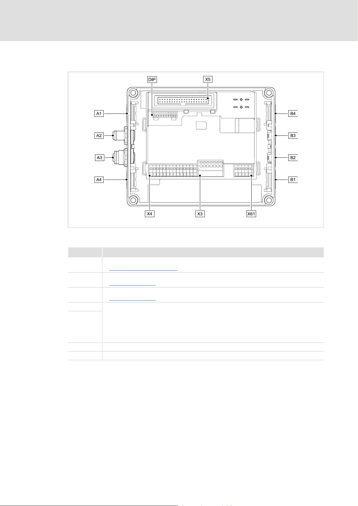
[3-1] CANopen communication unit
Pos. Description
DIP DIP switch
Possible settings via DIP switch
A2 CANopen input (M12 pins, 5-pole)
CANopen connection
A3 CANopen output (M12 socket, 5-pole)
CANopen connection
A1 / A4 Positions for further freely designable inputs and outputs:
B1 ... B4
X3 / X4 / X61 Terminal strips for wiring the connectors at A1 ... A4 and B1 ... B4
X5 Plug connector for connection to the drive unit
• Digital inputs
•Digital output
• Analog input (only for E84DGFCCxJx)
• Relay output (only for E84DGFCCxJx)
• Connection of safety system "Safety Option" (only for E84DGFCCxJx)
E84DG002
( 32)
( 29)
( 29)
EDS84DMOTCAN EN 3.0 - 11/2011 L 17
Page 18

Communication manual 8400 motec CANopen
Product description
Connections and interfaces
By default, the CANopen connectors are already pre-assembled and wired with the
terminal strip X3.
The CANopen connections and further connections (e.g. digital inputs) can be freely
designed at the positions A1 ... A4 and B1 ... B4..
The connections can be equipped with 5-pole M12 connectors, or optionally with cable
glands (cable cross-section max. 1.0 mm
The M12 connectors, cable glands and prefabricated system cables can be obtained
from various manufacturers.
Wire the M12 connectors or cable glands used to the corresponding contacts of
terminal strips X3, X4, and X61.
2
, AWG 18).
"Inverter Drives 8400 motec" hardware manual
Observe the notes and wiring instructions given in the documentation.
18 L EDS84DMOTCAN EN 3.0 - 11/2011
Page 19

Communication manual 8400 motec CANopen
General data and operating conditions of the CANopen
4 Technical data
"Inverter Drives 8400 motec" hardware manual
Here you will find the ambient conditions and information on the
electromagnetic compatibility (EMC) that also apply to the communication unit.
4.1 General data and operating conditions of the CANopen
Field Values
Order designation • E84DGFCCxNx (CANopen)
• E84DGFCCxJx (CANopen + Safety)
Communication profile CANopen, DS301 V4.02
Communication medium DIN ISO 11898
Interface • CANopen input: M12 pins, 5-pole, A-coded
• CANopen output: M12 socket, 5-pole, A-coded
Network topology Line terminated on both sides
Adjustable node address 1 ... 63 (can be set via DIP switch or code C00350
Max. number of nodes 63
Baud rate [kbps] 20, 50, 125, 250, 500, 800, 1000 kbps, adjustable via DIP switches or code
C00351
Process data • Max. 2 transmit PDOs (TPDOs) with 1 ... 8 bytes (adjustable)
• Max. 2 receive PDOs (RPDOs) with 1 ... 8 bytes (adjustable)
Parameter data Max. 2 server SDO channels with 1 ... 8 bytes
Transmission mode for TPDOs • With change of data
• Time-controlled, 1 to x ms
• After the reception of 1 to 240 sync telegrams
Conformities, approvals • CE
•UR / cUR
Technical data
)
EDS84DMOTCAN EN 3.0 - 11/2011 L 19
Page 20

Communication manual 8400 motec CANopen
Technical data
Supported protocols
4.2 Supported protocols
Protocols
Standard PDO protocols PDO write
PDO read
SDO protocols SDO download
SDO download initiate
SDO download segment
SDO upload
SDO upload initiate
SDO upload segment
SDO abort transfer
SDO block download
SDO block download initiate
SDO block download end
SDO block upload
SDO block upload initiate
SDO block upload end
NMT protocols Start remote node (master and slave)
Stop remote node (slave)
Enter pre-operational (slave)
Reset node (slave and local device)
Reset communication protocol (slave)
Monitoring protocols Heartbeat (heartbeat producer and heartbeat consumer)
• 1 Heartbeat Producer can be monitored.
Emergency telegram (to master)
20 L EDS84DMOTCAN EN 3.0 - 11/2011
Page 21

4.3 Communication time
The communication time is the time between the start of a request and the arrival of the
corresponding response.
The communication times in a CANopen network depend on ...
the processing time in the controller;
the telegram runtime (baud rate / telegram length);
the nesting depth of the network.
Processing time in the controller
Data Processing time
Process data Approx. 2 ms
Parameter data Approx. 30 ms + 20 ms tolerance (typical)
Communication manual 8400 motec CANopen
Technical data
Communication time
update cycle
+ 0 ... 1 ms
+ 1 ... x ms
• For some codes, the processing time may be longer (see software
manual/»Engineer« online help "Inverter Drives 8400 motec").
processing time in the module
application task runtime of the technology application used
(tolerance)
There are no interdependencies between parameter data and process data.
EDS84DMOTCAN EN 3.0 - 11/2011 L 21
Page 22

Communication manual 8400 motec CANopen
Installation
5 Installation
Stop!
Electrostatic discharge
Electronic components within the communication unit can be damaged or
destroyed by electrostatic discharge.
Possible consequences:
• The communication unit is defective.
• Communication via the fieldbus is not possible or faulty.
• I/O signals are faulty.
• The safety function is faulty.
Protective measures
• Discharge electrostatic charges before touching the communication unit.
22 L EDS84DMOTCAN EN 3.0 - 11/2011
Page 23
5.1 Mechanical installation
Mounting instructions for "Inverter Drives 8400 motec"
Here you will find detailed information on the installation.
0.37 ... 3.0 kW 4.0 ... 7.5 kW
Communication manual 8400 motec CANopen
Installation
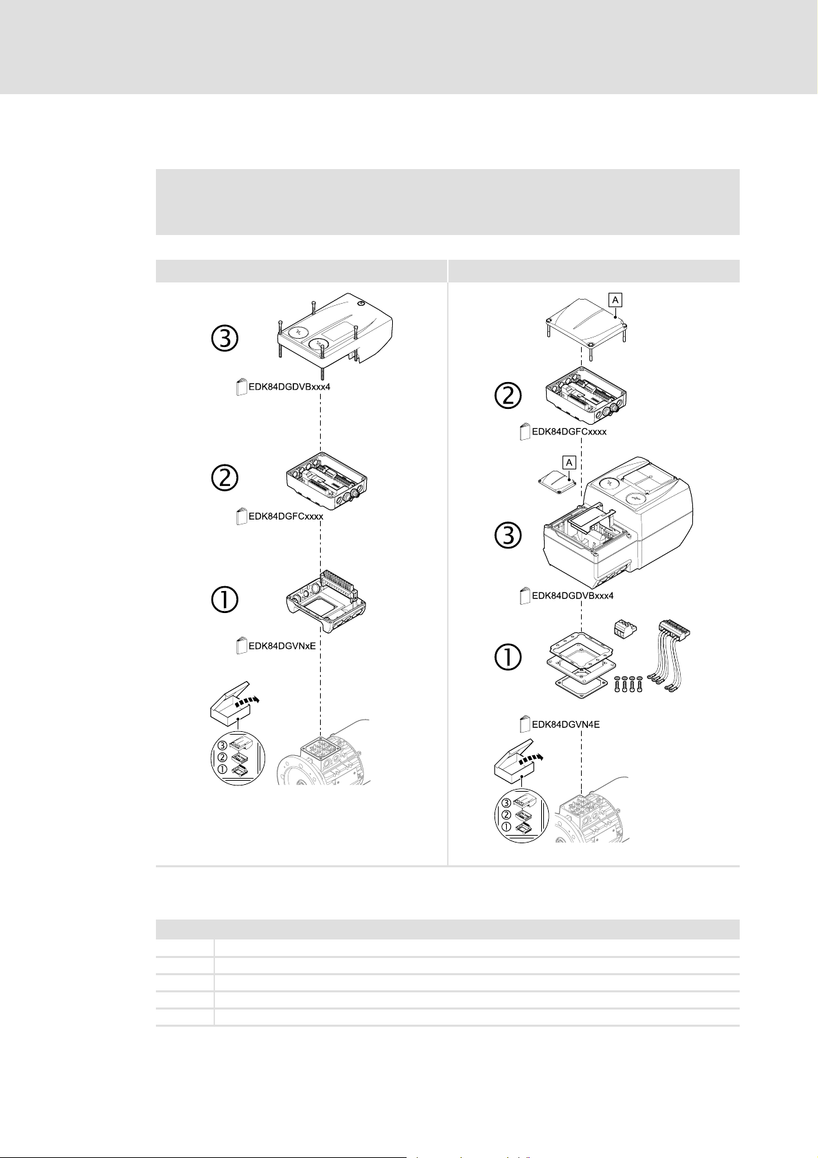
Mechanical installation
[5-1] Mechanical installation of the 8400 motec components
Legend for Fig. [5-1]
1 Drive unit
2 Communication unit
3 Wiring unit
A Cover of the drive unit
EDK84DG... Mounting instructions for the drive unit, communication unit, wiring unit
E84DG023a
E84DG023b
EDS84DMOTCAN EN 3.0 - 11/2011 L 23
Page 24
Communication manual 8400 motec CANopen
Installation
Electrical installation
5.2 Electrical installation
"Inverter Drives 8400 motec" hardware manual
Here you'll find detailed information on ...
• the digital and analog inputs and outputs;
• the relay output;
• the integrated safety system (safety option);
• the wiring of the connections.
Observe the notes and wiring instructions given in the documentation.
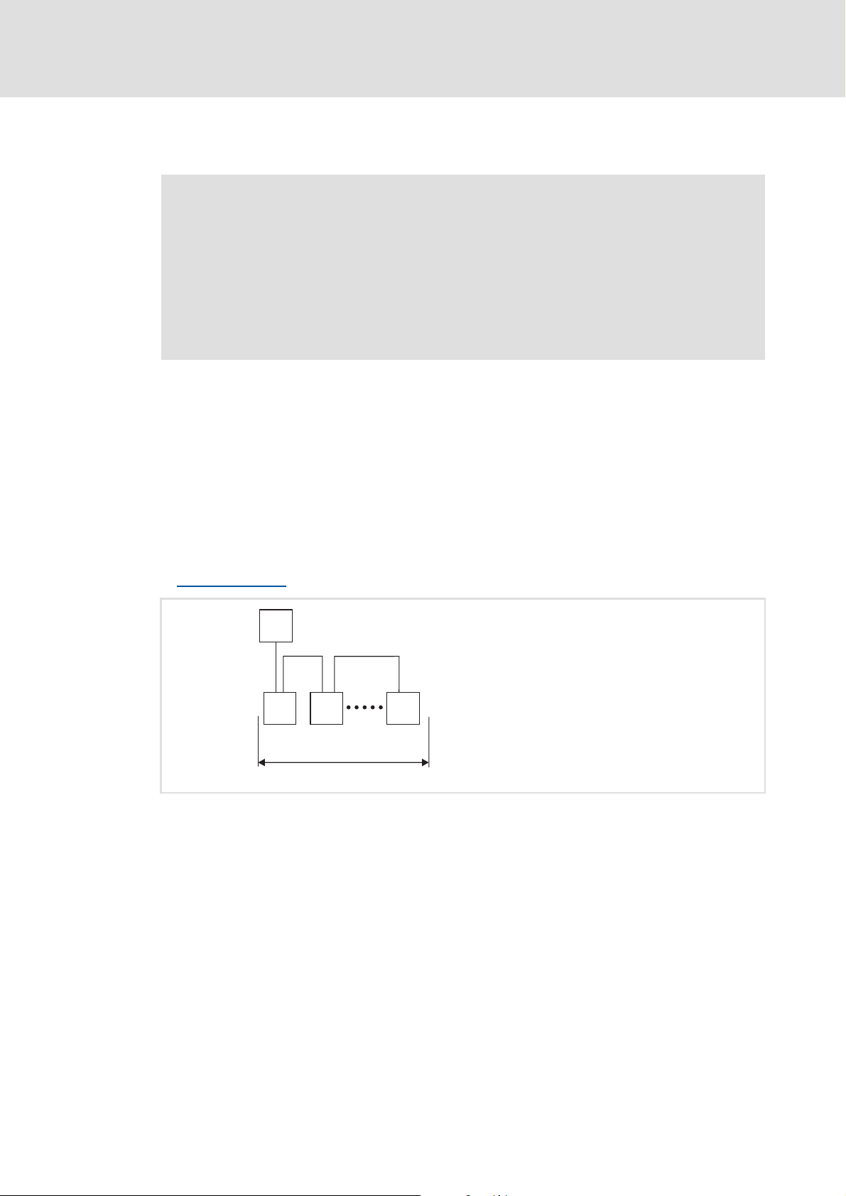
5.2.1 Network topology
The following examples show two simple CAN networks.
Each segment of the network must be terminated at both ends by resistors (120 Ω)
between CAN-Low and CAN-High. The bus terminators of the system bus (CAN) are marked
with a "Z" in the following examples.
A CAN network consisting of only one segment starts with the CAN master (M) with
integrated bus termination, whereas the last CAN node (S) has to be terminated by a bus
terminating resistor.
Bus termination
( 25)
M
Z
Z
S SS
1
[5-2] CAN network with one segment
E94YCPM012a
24 L EDS84DMOTCAN EN 3.0 - 11/2011
Page 25
Communication manual 8400 motec CANopen
Installation
Electrical installation
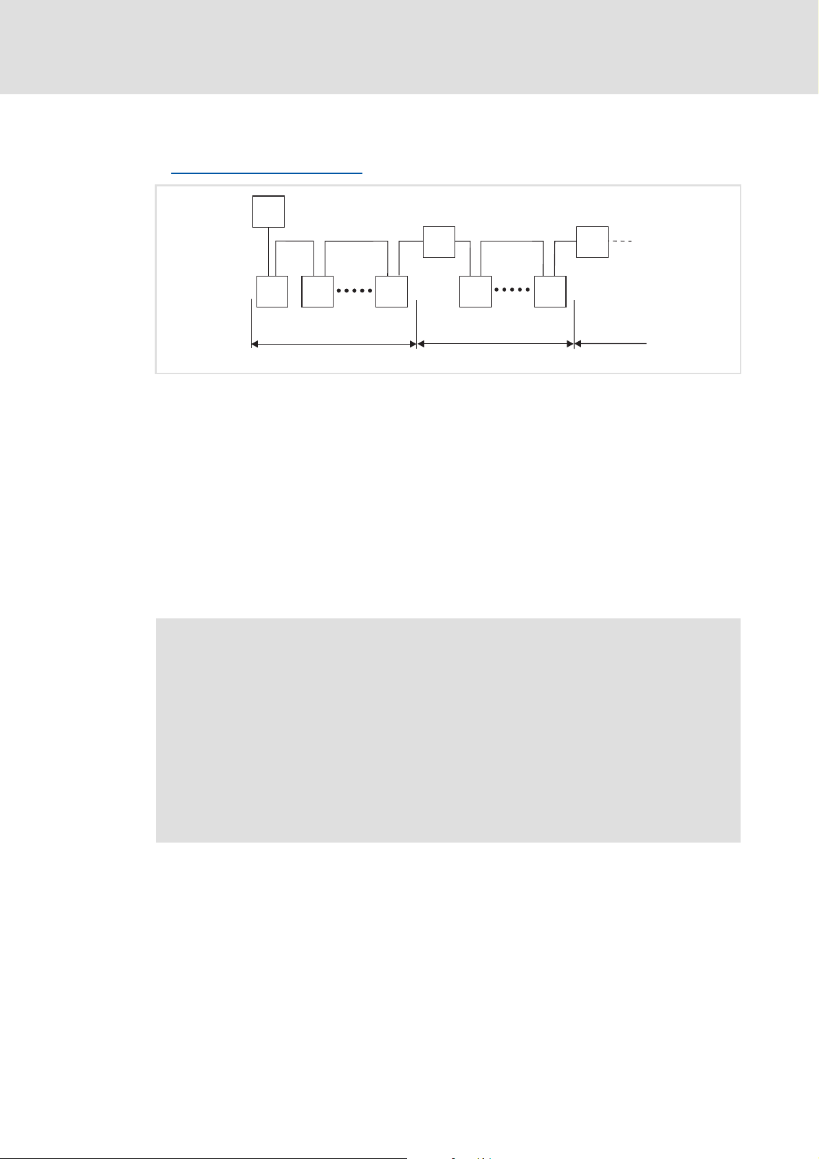
A CAN network consisting of several segments contains repeaters (R) for connecting the
segments. The repeaters are provided with integrated bus terminations.
Consider the use of repeaters
( 28)
M
Z
Z
Z
R
Z
Z
R
Z
[5-3] CAN network with repeaters
If no repeater is to be used at the end of the segment, the bus must be terminated by a bus
terminating resistor at the last node (S). The bus termination is supplied by the node itself.
5.2.2 Bus termination
The system bus (CANopen) must be terminated through a bus terminating resistor at the
first and last physical node (120 Ω).
In the case of the communication unit, the bus terminating resistor can only be installed
externally at the M12 connector. This has the advantage that the presence of the resistor
can be identified on the closed device.
Note!
• The CANopen terminals (input and output) must be installed so that they are
closed. For this purpose either use a connecting cable, a closed terminating
resistor plug (M12 pins, 5-pole, A-coded), or a cap.
• The connecting cable and terminating resistor plug can be procured freely
from various cable manufacturers (e.g. Lapp or Turck).
• If you want to disconnect individual nodes, ensure that the bus terminations
at the cable ends remain active. Otherwise the bus may become instable.
• Observe that the bus terminator is no longer active when the terminating
resistor plug has been removed.
S SS
S S
1 23
E94YCPM012b
EDS84DMOTCAN EN 3.0 - 11/2011 L 25
Page 26

Communication manual 8400 motec CANopen
Installation
Electrical installation
5.2.3 Specification of the bus cable
We recommend the use of CAN cables in accordance with ISO 11898-2:
CAN cable in accordance with ISO 11898-2
Cable type Paired with shielding
Impedance 120 Ω (95 ... 140 Ω)
Cable resistance/cross-section
Cable length ≤ 300 m
Cable length 301 ... 1000 m
Signal propagation delay ≤ 5 ns/m
≤ 70 mΩ/m / 0.25... 0.34 mm
≤ 40 mΩ/m / 0.5 mm
2
(AWG20)
2
(AWG22)
Observe the notes provided on the Bus cable length
5.2.4 Bus cable length
Note!
• It is absolutely necessary to comply with the permissible cable lengths.
• Please take into account the reduction of the total cable length due to the
• Mixed operation refers to different nodes being connected to the same
Total cable length
• If the total cable lengths of the nodes are different at the same baud rate, the
1. Check that the total cable length is not exceeded.
The total cable length is determined by the baud rate.
( 26)!
signal delay of the repeater.
Consider the use of repeaters
( 28)
network.
smaller value must be used to determine the maximum cable length.
Baud rate [kbps] Max. bus length [m]
20 4013
50 1575
125 600
250 275
500 113
800 38
1000 13
[5-1] Total cable length
26 L EDS84DMOTCAN EN 3.0 - 11/2011
Page 27
Communication manual 8400 motec CANopen
Segment cable length
2. Check that the segment cable length is not exceeded
The segment cable length is determined by the number of nodes and the cable
cross-section used. Without a repeater, the segment cable length corresponds to
the total cable length.
Installation
Electrical installation
Maximum number of
nodes per segment
2 240 m 430 m 650 m 940 m
5 230 m 420 m 640 m 920 m
10 230 m 410 m 620 m 900 m
20 210 m 390 m 580 m 850 m
32 200 m 360 m 550 m 800 m
63 170 m 310 m 470 m 690 m
[5-2] Segment cable length
3. Compare both values.
If the value determined from the Segment cable length
the required total cable length Total cable length
Repeaters divide the total cable length into segments.
Selection example
Given
• Cable cross-section: 0.5 mm
• Number of nodes: 63
• Repeater: Lenze repeater, type 2176 (cable reduction: 30 m)
Cable cross-section
0.25 mm
2
0.5 mm
2
0.75 mm
2
1 mm
[5-2] table is smaller than
[5-1], repeaters must be used.
2
, according to Specification of the bus cable ( 26)
2
Based on the given specifications, the following cable lengths/number of repeaters result
for a maximum of 63 nodes:
Baud rate [kbps] 20 50 125 250 500 800 1000
Max. cable length [m] 4013 1575 600 275 113 38 13
Segment cable length [m] 270 270 270 270 113 38 13
Number of repeaters 15621- - -
EDS84DMOTCAN EN 3.0 - 11/2011 L 27
Page 28

Communication manual 8400 motec CANopen
Installation
Electrical installation
Consider the use of repeaters
Note!
The use of an additional repeater is recommended as:
• Service interface
– Advantage: Trouble-free connecting during ongoing bus operation is
possible.
• Calibration interface
– Advantage: Calibration/programming units remain electrically isolated.
Given
• Baud rate: 125 kbps
• Cable cross-section: 0.5 mm
• Number of nodes: 28
• Cable length: 450 m
2
Steps Cable length See
1 Total cable length at 125 kbps: 600 m Table Total cable length
2 Segment cable length for 28 nodes and a
cable cross-section of 0.5 mm
3 Comparison: The value determined in
step 2 is smaller than the required cable
length of 450 m.
2
:
360 m Table Segment cable length
( 27)
Conclusion:
A cable length of 450 m is not possible without installing a repeater.
After 360 m (step 2), a repeater must be installed.
Result:
The Lenze repeater, type 2176 (cable reduction: 30 m), is used
Calculation of the max. cable length:
– First segment: 360 m
– Second segment: 360 m (according to the table Segment cable length
[5-2] ( 27))
minus 30 m (cable reduction when a repeater is used)
Max. possible cable length with one repeater: 690 m
– Now the required cable length is possible.
[5-1] ( 26)
[5-2]
28 L EDS84DMOTCAN EN 3.0 - 11/2011
Page 29
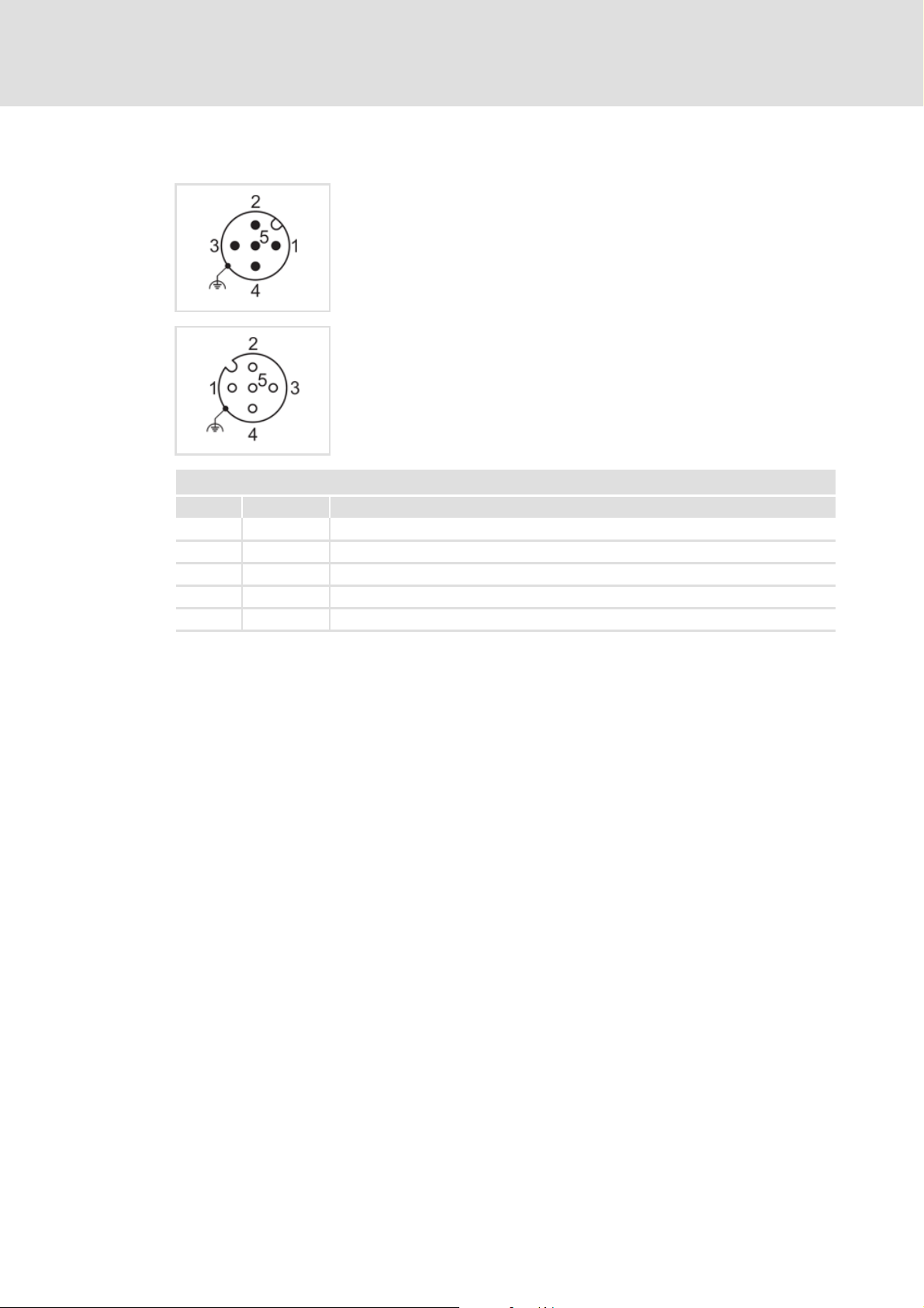
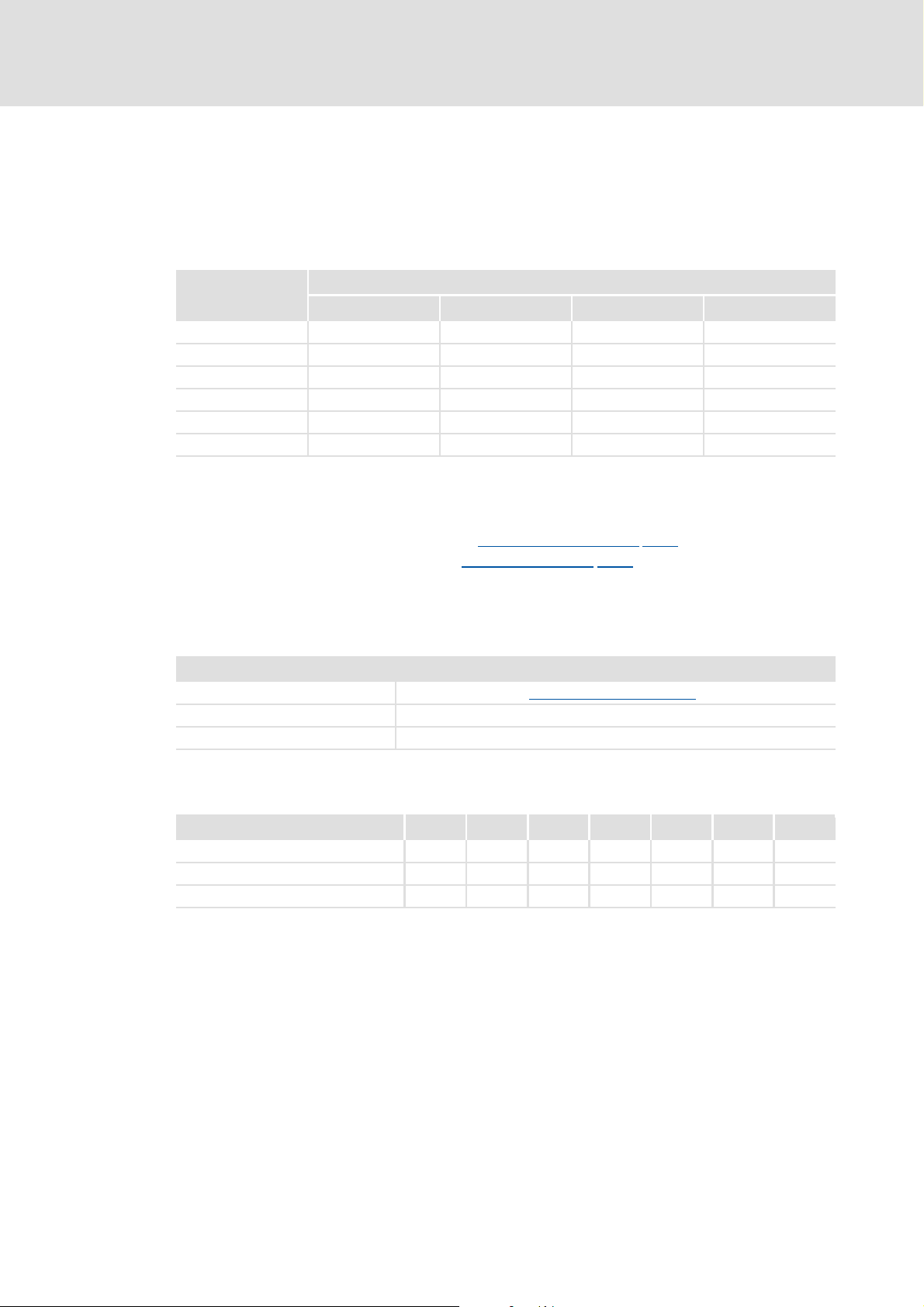
5.2.5 CANopen connection
CANopen connection
Pin Signal Description
1 - Not assigned
2 - Not assigned
3CG CAN GND potential
4 CH CAN-High data line
5CL CAN-Low data line
Communication manual 8400 motec CANopen
Installation
Electrical installation
Input: M12 pins, 5-pole, A-coded
Wiring at terminal strip X3
Output: M12 socket, 5-pole, A-coded
Wiring at terminal strip X3
EDS84DMOTCAN EN 3.0 - 11/2011 L 29
Page 30

Communication manual 8400 motec CANopen
Commissioning
Before initial switch-on
6 Commissioning
During commissioning, system-related data such as motor parameters, operating
parameters, responses, and parameters for fieldbus communication are defined for the
controller. For Lenze devices, this is done via the codes.
The codes of the controller and communication are saved non-volatilely as a data set in the
memory module.
In addition, other codes are also available for diagnosing and monitoring the nodes.
Parameter reference
6.1 Before initial switch-on
Stop!
Before switching on the device for the first time, please check ...
• the entire wiring for completeness, short circuit, and earth fault.
• whether the bus system is terminated through a bus terminating resistor at
the first and last physical node.
Bus termination
( 75)
( 25)
30 L EDS84DMOTCAN EN 3.0 - 11/2011
Page 31

6.2 Configuring the host (master)
First you have to configure the host (master) for the communication with the controller.
Defining the user data length
The CANopen communication unit supports the configuration of max. 8 process data
words (max. 64 bytes).
The user data length is defined during the initialisation phase of the master.
The user data lengths for process input data and process output data are the same.
Note!
The CANopen process data objects are designated as seen from the node's view:
• Receive PDO (RPDOx): Process data object received by a node
• Transmit PDO (TPDOx): Process data object sent by a node
Communication manual 8400 motec CANopen
Commissioning
Configuring the host (master)
EDS84DMOTCAN EN 3.0 - 11/2011 L 31
Page 32

Communication manual 8400 motec CANopen
Commissioning
Possible settings via DIP switch
6.3 Possible settings via DIP switch
The DIP switches serve to ...
[6-1] DIP switch
Note!
• The DIP switches can only be accessed when the drive unit is detached from
the communication unit. Loosen the four fixing screws at the drive unit.
Observe the notes in the mounting instructions.
• Switch off the voltage supply of the controller and the external supply of the
communication unit before starting with the dismounting of the drive unit.
• The DIP switches are only read in when the device is switched on.
6.3.1 Setting the baud rate
The baud rate ...
must be the same for all networked CANopen nodes;
Setting the baud rate
( 32) (switches: a ... c)
Setting the CAN node address
(switches: 1 ... 64)
Lenze setting: All switches OFF
( 33)
can be set via the DIP switches a...c or via the »Engineer« (code C00351
DIP switch position Baud rate
c b a
ON OFF ON 20 kbps
OFF ON ON 50 kbps
OFF ON OFF 125 kbps
OFF OFF ON 250 kbps
OFF OFF OFF 500 kbps
ON ON OFF 800 kbps
ON OFF OFF 1000 kbps
Settings in the Lenze »Engineer«
( 34)
).
32 L EDS84DMOTCAN EN 3.0 - 11/2011
Page 33

6.3.2 Setting the CAN node address
The node addresses must differ from each other in the case of several networked CANopen
nodes.
The node address can be set via DIP switches 1...64 or via the »Engineer« with code
C00350
.
Communication manual 8400 motec CANopen
Commissioning
Possible settings via DIP switch
For the setting with C00350
DIP switches 1...64must be set toOFF.
Note!
• The valid address range is 0 ... 63.
• If DIP switch 64 = ON (node address > 63), always node address 63 is used.
DIP switch Node address
64 32 16 8 4 2 1
OFF OFF OFF OFF OFF OFF OFF Value from C00350
OFF OFF OFF OFF OFF OFF ON 1
OFF ... ... ... ... ... ... ...
OFF ON ON ON ON ON ON 63
ON ... ... ... ... ... ...
The labelling on the housing corresponds to the values of the individual DIP switches for
determining the node address.
DIP switch 64 32 16 8 4 2 1
Switch position OFF OFF ON OFF ON ON ON
Value 00
Node address = Sum of the values = 16 + 4 + 2 + 1 = 23
16 0 4 2 1
The current address setting of the DIP switches is displayed in C00349
DIP switch positions for setting the CAN node address
Settings in the Lenze »Engineer«
( 34)
( 106)
.
EDS84DMOTCAN EN 3.0 - 11/2011 L 33
Page 34

Communication manual 8400 motec CANopen
Commissioning
Settings in the Lenze »Engineer«
6.4 Settings in the Lenze »Engineer«
The following settings can be made in the »Engineer« under the Settings tab:
CAN node address (C00350
– The node address can only be parameterised if the node address "0" is set via the DIP
switches.
– A change of the node address will only become effective after a CAN reset node.
CAN node is slave or master (C00352
Deceleration during status change from "Boot-up" to "Operational" (C00356/1
Time to the first transmission of CANx_OUT in the "Operational" state (C00356/4)
)
)
)
Save changed settings with the device command C00002/11 (save all parameter sets).
34 L EDS84DMOTCAN EN 3.0 - 11/2011
Page 35

6.5 Initial switch-on
Establishing communication
To establish communication, the controller must be supplied with mains voltage.
All parameters (codes) and DIP switch settings are read in when the device is switched
on.
If an error occurs, the error message "CE04: MCI communication error" (error no.
01.0127.00002) is output.
The positions of the DIP switches define whether the CAN node address and the baud
rate are selected via the DIP switches or via codes C00350
Possible settings via DIP switch
Communication manual 8400 motec CANopen
Commissioning
Initial switch-on
and C00351.
( 32)
EDS84DMOTCAN EN 3.0 - 11/2011 L 35
Page 36

Communication manual 8400 motec CANopen
Data transfer
Structure of the CAN data telegram
7 Data transfer
Via the system bus interface, for instance process data and parameter values can be
exchanged between the nodes. In addition, the interface enables the connection of
additional modules such as distributed terminals, keypads and input devices or external
control systems and hosts (masters).
The system bus interface transfers CAN objects following the CANopen communication
profile (CiA DS301, version 4.02) developed by the umbrella organisation of CiA (CAN in
Automation) in conformity with the CAL (CAN Application Layer).
7.1 Structure of the CAN data telegram
6WDUW 575ELW
,GHQWLILHU 8VHUGDWD
%LW %LW %LW %LW %LW %LW %LW %LW %LW
[7-1] Basic structure of the CAN telegram
&RQWUROILHOG
&5&VHTXHQFH
%\WH
1HWZRUNPDQDJHPHQW
3URFHVVGDWD
3DUDPHWHUGDWD
&5&GHOLPLWHU $&.GHOLPLWHU
$&.VORW (QG
The following subchapters provide a detailed description of the identifier and the user
data. The other signals refer to the transfer characteristics of the CAN telegram the
description of which is not included in the scope of this documentation.
Tip!
Please visit the homepage of the CAN user organisation CiA (CAN in automation)
for further information:
http://www.can-cia.org
36 L EDS84DMOTCAN EN 3.0 - 11/2011
Page 37

7.1.1 Identifier
The principle of CAN communication is based on a message-oriented data exchange
between a transmitter and many receivers. All nodes can virtually transmit and receive
simultaneously.
The identifier, also called COB-ID (abbr. for communication object identifier), is used to
control which node is to receive a transmitted message. In addition to the addressing, the
identifier contains information on the priority of the message and the type of user data.
The identifier consists of a basic identifier and the node address of the node to be
addressed:
Identifier (COB-ID) = basic identifier + node address (node ID)
Communication manual 8400 motec CANopen
Data transfer
Structure of the CAN data telegram
Exception:
management and sync telegrams is freely assigned by the user (either manually or
automatically by the network configurator), or is permanently assigned.
Node address (node ID)
For unambiguous identification, a node address (also called node ID) within the valid
address range (1 ... 63) must be assigned to every node of the system bus network.
A node address may not be assigned more than once within a network.
The own node address can be configured via the DIP switches or via code C00350
Setting the CAN node address
Identifier assignment
The system bus is message-oriented instead of node-oriented. Every message has an
unambiguous identification, the identifier. For CANopen, node-oriented transfer is
achieved by the fact that every message has only one transmitter.
The basic identifiers for network management (NMT) and sync as well as the basic SDO
channel (SDO1) are defined in the CANopen protocol and cannot be changed.
In the Lenze setting, the basic identifiers of the PDOs are preset according to the
"Predefined connection set" of DS301, V4.02 and can be changed via parameters/
indexes, if required.
The identifier for process data/heartbeat/emergency objects as well as network
.
( 33)
Identifiers of the process data objects
EDS84DMOTCAN EN 3.0 - 11/2011 L 37
( 51)
Page 38

Communication manual 8400 motec CANopen
Data transfer
Structure of the CAN data telegram
Object Direction Lenze-Base-ID CANopen-Base-ID
from device to device dec hex dec hex
Network management (NMT) 0 0 0 0
1)
Sync
Emergency
PDO1
(Process data channel 1)
PDO2
(Process data channel 2)
SDO1
(Parameter data channel 1)
SDO2
(Parameter data channel 2)
Heartbeat z 1792 700 1792 700
Boot-up z 1792 700 1792 700
1)
TPDO1
RPDO1
TPDO2
RPDO2
TSDO1
RSDO1
TSDO2
RSDO2
z 128 80 128 80
z 384 180 384 180
z 640 280 640 280
z 1408 580 1408 580
z 1472 5C0 1472 5C0
128 80 128 80
z 512 200 512 200
z 641 281 768 300
z 1536 600 1536 600
z 1600 640 1600 640
1) If you set the sync transmit/receive identifier manually, observe the use of the emergency telegram, since it has the same
COB-ID.
38 L EDS84DMOTCAN EN 3.0 - 11/2011
Page 39

7.1.2 User data
All nodes communicate by exchanging data telegrams via the system bus. The user data
area of the CAN telegram either contains network management data, or parameter data,
or process data:
Network management data
(NMT data)
Control information on start, stop, reset, etc. of communication to specific nodes or to
all nodes of the CAN network.
Process data
(PDOs – process data objects)
Process data are transferred via the process data channel.
Process data can be used to control the controller.
Communication manual 8400 motec CANopen
Data transfer
Structure of the CAN data telegram
Process data are not
Process data are transmitted between the host (master) and controllers (slaves) to
ensure a continuous exchange of current input and output data.
Process data usually are unscaled/scalable raw data.
Process data are, for instance, setpoints and actual values.
The exact meaning of the PDO file contents is determined via the function block editor
(FB Editor) in the I/O level or via the PDO mapping.
Parameter data
(SDOs – service data objects)
Parameter data are the CANopen indexes or, in the case of Lenze devices, the codes.
Parameters are, for instance, used for one-off plant setting during commissioning or
when the material on a production machine is changed.
Parameter data are transmitted as SDOs via the parameter data channel. They are
acknowledged by the receiver, i.e. the sender gets a feedback about whether the
transmission was successful or not.
The parameter data channel enables access to all Lenze codes and CANopen indexes.
Parameter changes are automatically saved to the controller until mains switching.
saved to the controller.
Generally the parameter transfer is not time-critical.
Parameter data are, for instance, operating parameters, diagnostic information, and
motor data.
EDS84DMOTCAN EN 3.0 - 11/2011 L 39
Page 40

Communication manual 8400 motec CANopen
Data transfer
Communication phases/network management
7.2 Communication phases/network management
With regard to communication via the system bus, the controller distinguishes between
the following states:
Status Explanation
"Initialisation"
(Initialisation)
"Pre-operational"
(before being ready for operation)
"Operational"
(ready for operation)
"Stopped"
(stopped)
After switch-on, an initialisation run is carried out.
• During this phase, the controller is not involved in the data exchange via
the bus.
• The standard values are re-written to all CAN-relevant parameters.
• After initialisation is completed, the controller is automatically set to the
"Pre-operational" status.
Parameter data can be received, process data are ignored.
Parameter data and process data can be received!
Only network management telegrams can be received.
Communication object Initialisation Pre-operational Operational Stopped
PDO z
SDO zz
Sync zz
Emergency zz
Boot-up z
Network management (NMT) zzz
Code C00359
serves to display the status of the CAN bus.
Tip!
Part of the initialisation or the entire initialisation can be carried out again in every
status by transmitting the corresponding network management telegrams.
40 L EDS84DMOTCAN EN 3.0 - 11/2011
Page 41

7.2.1 State transitions
[7-2] NMT state transitions in the CAN network
Communication manual 8400 motec CANopen
Data transfer
Communication phases/network management
,QLWLDOLVDWLRQ
3UH2SHUDWLRQDO
2SHUDWLRQDO
6WRSSHG
Transition NMT command Status after
Effects on process/parameter data after status change
change
(1) - Initialisation Initialisation starts automatically at mains connection.
• During initialisation, the controller is not involved in the
data exchange.
• After the initialisation is completed, the node sends a
boot-up message with an individual identifier and
automatically changes to the "Pre-operational" status.
(2) - Pre-operational In this phase, the master determines the way in which the
node(s) takes/take part in communication.
From here, the master changes the states for the entire network.
• A target address included in the NMT command defines the receiver(s).
• If the controller is configured as CAN master, the status is automatically changed to
"Operational" after a waiting time has expired (C00356/1
) and the command 0x0100 NMT
("Start Remote Node") is transmitted to all nodes.
• Data can only be exchanged via process data objects if the status is "Operational"!
(3), (6) 0x01 xx
Start remote node
Operational Network management/sync/emergency telegrams as well
as process data (PDO) and parameter data (SDO) are active.
Optional: When the status is changed, event- and time-
controlled process data (PDOs) are transmitted once.
(4), (7) 0x80 xx
Enter Pre-operational
(5), (8) 0x02 xx
Stop remote node
(9), (10), (11) 0x81 xx
Reset node
(12), (13), (14) 0x82 xx
Reset communication
Pre-operational Network management/sync/emergency telegrams and
parameter data (SDO) are active.
Stopped Only network management telegrams can be received.
Initialisation All CAN-relevant parameters (CiA DS 301) are initialised with
the saved values.
All CAN-relevant parameters (CiA DS 301) are initialised with
the saved values.
Meaning of the node address in the NMT command:
• xx = 0x00: If this assignment is selected, the telegram addresses all nodes (broadcast telegram).
The status of all nodes can be changed at the same time.
• xx = Node ID: If a node address is specified, only the status of the node with the corresponding
address changes.
EDS84DMOTCAN EN 3.0 - 11/2011 L 41
Page 42

Communication manual 8400 motec CANopen
Data transfer
Communication phases/network management
7.2.2 Network management telegram (NMT)
The telegram for the network management contains the identifier "0" and the command
included in the user data, which consists of the command byte and the node address:
,GHQWLILHU 8VHUGDWD%\WH
&2%,'
%LW %LW %LW %LW %LW %LW %LW %LW %LW
[7-3] Network management telegram for changing over the communication phases
Command specifier (cs) NMT command
dec hex
1 0x01 Start remote node
20x02Stop remote node
128 0x80 Enter Pre-operational
129 0x81 Reset node
130 0x82 Reset communication
FRPPDQG
VSHFLILHU
FV
QRGH
DGGUHVV
QRGH,'
The change-over of the communication phases for the entire network is carried out by one
node, the CAN master. The function of the CAN master can also be carried out by the
controller.
Parameterising the Inverter Drives 8400 motec as CAN master
( 43)
Example:
Data can only be exchanged via process data objects if the status is "Operational". If the
CAN master is supposed to switch all nodes connected to the bus from the "Preoperational" communication status to the "Operational" communication status, the
identifier and user data in the transmission telegram must be set as follows:
Identifier: 0x00 (network management)
User data: 0x0100 ("Start remote node" NMT command to all nodes)
42 L EDS84DMOTCAN EN 3.0 - 11/2011
Page 43

Communication manual 8400 motec CANopen
Communication phases/network management
7.2.3 Parameterising the Inverter Drives 8400 motec as CAN master
If the initialisation of the system bus and the associated status change from "Preoperational" to "Operational" is not effected by a higher-level host, the Inverter Drive 8400
motec can instead be defined to be a "quasi" master to execute this task.
Data transfer
The controller is configured as CAN master in C00352
Being the CAN master, the controller sets all
telegram) to the "Operational" communication status with the "Start remote node"
NMT telegram. Only in this communication status data can be exchanged via process
data objects.
A delay time can be set in C00356/1
the controller transmits the "Start remote node" NMT telegram.
Parameter Info Lenze setting
C00352 CAN slave/master Slave
C00356/1
CAN delay boot-up - Operational 3000 ms
, which must expire after mains switching before
.
nodes connected to the bus (broadcast
Value Unit
Note!
The changes of the master/slave operation in C00352 will not be activated until
• another mains switching of the controller
or
• the "Reset node" or "Reset communication" NMT telegram has been
transmitted to the controller.
The "CAN reset node" device command (C00002/26) is provided as an alternative
to the "Reset node" NMT telegram for the reinitialisation of the CAN-specific
device parameters.
Tip!
Master functionality is only required during the initialisation phase of the drive
system.
EDS84DMOTCAN EN 3.0 - 11/2011 L 43
Page 44

Communication manual 8400 motec CANopen
Process data transfer
8 Process data transfer
[8-1] PDO data transfer from / to the higher-level host (master)
The CANopen communication unit is provided with two separate process data channels
(PDO1 and PDO2) for transmitting process data. Each process data channel can transmit up
to four words (8 bytes) at a maximum.
The system bus (CANopen) transmits parameter data, configuration data, diagnostic data,
alarm messages and process data between the host (master) and the controllers (slaves)
participating on the fieldbus. Depending on their time-critical nature, the data are
transmitted via different communication channels.
Process data are transmitted via the process data channel.
The process data serve to control the controller.
Transferring process data is time-critical.
Process data are transferred cyclically between the master and the slaves participating
on the fieldbus (continuous exchange of current input and output data).
The master can directly access the process data. In the PLC, for instance, the data are
directly assigned to the I/O area.
Process data are not saved in the controller.
Process data are, for instance, setpoints, actual values, control words and status words.
44 L EDS84DMOTCAN EN 3.0 - 11/2011
Page 45

Communication manual 8400 motec CANopen
Process data transfer
Definitions
Process data telegrams between the host (master) and the controllers (slaves) are
distinguished in terms of direction as follows:
– Process data telegrams to
– Process data telegrams from
The CANopen process data objects are designated as seen from the node's view:
– Receive PDOs (RPDOx): Process data object received by a node
– Transmit PDOs (TPDOx): Process data object sent by a node
the device (RPDO)
the device (TPDO)
Note!
Data can only be exchanged via process data objects if the status is
"Operational"!
Communication phases/network management
( 40)
EDS84DMOTCAN EN 3.0 - 11/2011 L 45
Page 46

Communication manual 8400 motec CANopen
Process data transfer
Access to process data / PDO mapping
8.1 Access to process data / PDO mapping
The process data are transferred via the MCI/CAN interface.
Max. 8 words (16 bits/word) per direction can be exchanged.
– 2 x 4 words via the input ports CAN1_IN and CAN2_IN
– 2 x 4 words via the output ports CAN1_OUT and CAN2_OUT
The process data are accessed via the port blocks LP_Network_In and
LP_Network_Out. These port blocks are also called process data channels.
The port/function block interconnection of the process data objects (PDO) takes place
via the Lenze »Engineer«.
[8-2] External and internal data transfer between the bus system, controller, and application
Software manual / »Engineer« online help "Inverter Drives 8400 motec"
Here you will find detailed information on port blocks and port/function block
interconnection in the »Engineer«.
46 L EDS84DMOTCAN EN 3.0 - 11/2011
Page 47

Communication manual 8400 motec CANopen
Port interconnection of the process data objects (PDO)
8.2 Port interconnection of the process data objects (PDO)
Note!
The »Engineer« screenshots shown on the following pages are only examples for
the setting sequence and the resulting screens.
Depending on the software version of the controller and of the »Engineer«
software installed, the screenshots may deviate from your »Engineer«
representation.
The preconfigured port interconnection of the process data objects is activated by setting
code C00007 = 40: Network (MCI/CAN).
How to freely configure the port interconnection in the »Engineer«:
1. Under the Process data object tab, click the Go to application button.
Process data transfer
2. The Ports tab displays the port blocks CAN1_IN/CAN2_IN and CAN1_OUT/
CAN2_OUT.
EDS84DMOTCAN EN 3.0 - 11/2011 L 47
Page 48

Communication manual 8400 motec CANopen
Process data transfer
Port interconnection of the process data objects (PDO)
3. Click the port to be configured and press the Edit port ... button.
48 L EDS84DMOTCAN EN 3.0 - 11/2011
Page 49

Communication manual 8400 motec CANopen
Process data transfer
Port interconnection of the process data objects (PDO)
4. Via the button, you can assign signals to the process data words in the Signal
assignment --> Function Block dialog box.
Select the signals and then confirm the selection with the OK button.
EDS84DMOTCAN EN 3.0 - 11/2011 L 49
Page 50

Communication manual 8400 motec CANopen
Process data transfer
Port interconnection of the process data objects (PDO)
For some process data words, you can also assign signals to the individual bits via
the and buttons.
Select the signals and then confirm the selection with OK.
The current interconnection is only displayed if the following has been set for the
control mode in code C00007 = 40: Network (MCI/CAN).
50 L EDS84DMOTCAN EN 3.0 - 11/2011
Page 51

Communication manual 8400 motec CANopen
8.3 Identifiers of the process data objects
In the Lenze setting, the identifier for the process data objects PDO1 and PDO2 consists of
a basic identifier (CANBaseID) and the node address set in C00350
Identifier (COB-ID) = basic identifier + node address (node ID)
The basic identifiers of the PDOs comply with the "Predefined connection set" of
DS301, V4.02.
Process data transfer
Identifiers of the process data objects
:
Alternatively, define via code C00353
that the identifiers of the PDOs are to be assigned
according to Lenze definition or that individual settings are to be made.
–If C00353
= "2: COBID = C0354/x", the identifiers of the PDOs can be set individually
via the Lenze codes and CANopen indexes listed in the table below. That way,
identifiers independent of the node address can be set for specific PDOs.
– If identifiers are assigned individually, all PDOs must have basic identifier values in
the range of 385 ... 1407.
Process data object Basic identifier Individual setting
dec hex Lenze code CANopen index
PDO1
RPDO1 512 0x200 C00354/1
TPDO1 384 0x180 C00354/2 I-1800/1
PDO2
RPDO2 768 0x300 C00354/3
TPDO2 640 0x280 C00354/4 I-1801/1
I-1400/1
I-1401/1
Note!
After a node address change (C00350) and a subsequent CAN reset node, the
subcodes of C00354
respective basic identifier and the node address set.
automatically resume the values which result from the
Short overview: Parameters for setting the identifiers
Parameter Info Lenze setting
Value Unit
C00353/1 COBID source CAN1_IN/OUT 0: COBID = C0350 + CANBaseID
C00353/2
C00354/1
C00354/2
C00354/3
C00354/4
EDS84DMOTCAN EN 3.0 - 11/2011 L 51
COBID source CAN2_IN/OUT 0: COBID = C0350 + CANBaseID
COBID CAN1_IN 0x00000201
COBID CAN1_OUT 0x00000181
COBID CAN2_IN 0x00000301
COBID CAN2_OUT 0x00000281
Page 52

Communication manual 8400 motec CANopen
Process data transfer
Transmission type
8.4 Transmission type
Process data objects can be transmitted in an event-controlled or time-controlled manner.
The below table shows that it is possible to combine the different methods by means of
logic operations (AND, OR):
Event-controlled
The PDO is sent when a certain device-internal event has occurred, e.g. when the data
contents of the TPDO have changed or when a transmission cycle time has elapsed
Synchronous transmission
A TPDO (or RPDO) is sent (or received) after the device has received a sync telegram
(COB-ID 0x80).
Cyclic transmission
The cyclic transmission of PDOs takes place when the transmission cycle time has
elapsed.
Polled via RTR
A TPDO is sent when another device requests it by means of a data request telegram
(RTR remote transmit request). For this purpose, the data requester (e.g. the master)
sends the data request telegram with the COB-ID of the TPDO requested to be sent. The
receiver recognises the RTR and transmits the corresponding PDO.
Transmission type PDO transmission Logic combination of
cyclic synchronous event-controlled
0 zzAND
1 ... 240 zz AND
254 zzOR
Transmission type Description
0 Synchronous and acyclic:
The PDO is transmitted on an event-controlled basis with every sync (e.g. when a bit change
occurs in the PDO).
1 ... 240 Synchronous and cyclic (sync-controlled with response):
• Selection n = 1: The PDO is transmitted with every
• Selection 1 < n ≤ 240: The PDO is transmitted with every n-th
241 ... 251 Reserved
252, 253 RTR-controlled manner is not permissible.
254 Event-controlled with cyclic transmission:
If this value is entered, the PDO is transferred in an event-controlled or cyclic manner. (The
values "254" and "255" are equivalent).
For a cyclic transmission, a cycle time must be set for the respective PDO. In this case, cyclic
transmission takes place in addition to event-controlled transmission.
255 Not permissible
sync.
different
transmission types
sync.
52 L EDS84DMOTCAN EN 3.0 - 11/2011
Page 53

Communication manual 8400 motec CANopen
Process data transfer
Transmission type
The communication parameters such as the transmission mode and cycle time can be set
freely for every PDO and independently of the settings of other PDOs:
Parameter Info Lenze setting
Value Unit
C00322/1 Transmission mode CAN1 OUT 254
C00322/2
C00323/1
C00323/2
C00324/1
C00324/2
C00324/3
C00356/5
C00356/2
Transmission mode CAN2 OUT 254
Transmission mode CAN1 IN 254
Transmission mode CAN2 IN 254
Inhibit time for emergency telegrams 0 ms
CAN1_OUT inhibit time 0 ms
CAN2_OUT inhibit time 0 ms
CAN1_OUT cycle time 0 ms
CAN2_OUT cycle time 0 ms
Tip!
The setting can also be carried out via the following CANopen objects:
• I-1400
• I-1800
/ I-1401: Communication parameter for RPDO1 and RPDO2
/ I-1801: Communication parameter for TPDO1 and TPDO2
EDS84DMOTCAN EN 3.0 - 11/2011 L 53
Page 54

Communication manual 8400 motec CANopen
Process data transfer
PDO synchronisation via sync telegram
8.5 PDO synchronisation via sync telegram
During cyclic transmission, one or more PDOs are transmitted/received in fixed time
intervals. An additional specific telegram, the so-called sync telegram, is used for
synchronising cyclic process data.
The sync telegram is the trigger point for the transmission of process data from the
slaves to the master and for the acceptance of process data from the master in the
slaves.
For sync-controlled process data processing, the sync telegram must be generated
accordingly.
The response to a sync telegram is determined by the selected transmission type.
Transmission type
Basic workflow
n Sync cycle time
[8-3] Sync telegram
A. After the sync telegram has been received, the slaves transmit the synchronous process
data to the master (TPDOs). The master reads them as process input data.
B. When the transmission process is completed, the slaves receive (RPDOs) the process
output data (of the master).
– All other telegrams (e.g. parameters or event-controlled process data) are accepted
acyclically by the slaves after the transmission is completed.
–Illustration [8-3]
when dimensioning the cycle time.
( 52)
SYNC SYNC
01 2
does not include acyclic data. However, they need to be considered
C. The data are accepted in the slave with the next sync telegram if the Rx mode is set to
1 ... 240. If the Rx mode is 254 or 255, the data are accepted in the next device cycle,
irrespective of the sync telegram.
Short overview: Parameters for the synchronisation via sync telegram
Parameter Info Lenze setting Assignment
Value Unit Sync
C00367 CAN sync Rx identifier 128 z
C00368
C00369
54 L EDS84DMOTCAN EN 3.0 - 11/2011
CAN sync Tx identifier 128 z
CAN sync transmission cycle time 0 ms z
master
Sync
slave
Page 55

9 Parameter data transfer
Communication manual 8400 motec CANopen
Parameter data transfer
[9-1] Parameter data transfer via the available parameter data channels
Parameters are values stored in codes on Lenze controllers.
Two parameter data channels are available for parameter setting, enabling the
simultaneous connection of different devices for configuration purposes.
Parameter data are transmitted via the system bus as SDOs (Service Data Objects) via the
system bus (CANopen) and are acknowledged by the receiver. The SDO enables read and
write access to all device parameters and to the CANopen object directory integrated in the
device. Indexes (e.g. 0x1000) enable access to device parameters and functions included in
the object directory. To transfer SDOs, the information contained in the user data must
comply with the CAN-SDO protocol.
EDS84DMOTCAN EN 3.0 - 11/2011 L 55
Page 56

Communication manual 8400 motec CANopen
Parameter data transfer
Identifiers of the parameter data objects
9.1 Identifiers of the parameter data objects
In the Lenze setting, the basic identifiers of the SDOs are preset according to the
"Predefined Connection Set".
The identifiers for the parameter data objects SDO1 and SDO2 are generated from the
basic identifier and the node address set in code C00350
Identifier = basic identifier + node address
Object Direction Lenze-Base-ID CANopen-Base-ID
from device to device dec hex dec hex
SDO1
(Parameter data channel 1)
SDO2
(Parameter data channel 2)
Heartbeat z 1792 700 1792 700
Boot-up z 1792 700 1792 700
TSDO1
RSDO1
TSDO2
RSDO2
z 1408 580 1408 580
z 1472 5C0 1472 5C0
:
z 1536 600 1536 600
z 1600 640 1600 640
Note!
Please observe that the parameter data channels 1 and 2 are active in the factory
setting.
56 L EDS84DMOTCAN EN 3.0 - 11/2011
Page 57

9.2 User data
Structure of the user data of the parameter data telegram
1st byte 2nd byte 3rd byte 4th byte 5th byte 6th byte 7th byte 8th byte
Command Index Subindex Data 1 Data 2 Data 3 Data 4
Note!
For the user data, the Motorola format is used.
Communication manual 8400 motec CANopen
Parameter data transfer
User data
Low byte High byte Low word High word
Low byte High byte Low byte High byte
Parameter data telegram examples
The following subchapters provide detailed information on user data.
9.2.1 Command
1st byte 2nd byte 3rd byte 4th byte 5th byte 6th byte 7th byte 8th byte
Command Index Subindex Data 1 Data 2 Data 3 Data 4
The following commands can be transmitted or received for writing and reading the
parameters:
Command 1st byte Data length Info
Write request 0x23 35 4 bytes Writing of a parameter to the controller.
Write response 0x60 96 4 bytes Controller acknowledges a write request.
Read request 0x40 64 4 bytes Reading of a parameter from the controller.
Read response 0x43 67 4 bytes Controller's response to a read request with the current
Error response 0x80 128 4 bytes Response of the controller if the write/read request could
( 62)
Low byte High byte Low word High word
Low byte High byte Low byte High byte
hex dec
0x2B 43 2 bytes
0x2F 47 1 byte
0x21 33 Block
0x4B 75 2 bytes
0x4F 79 1 byte
0x41 65 Block
parameter value.
not be executed correctly.
Error messages
( 60)
EDS84DMOTCAN EN 3.0 - 11/2011 L 57
Page 58

Communication manual 8400 motec CANopen
Parameter data transfer
User data
More precisely, the command byte comprises the following information:
Command 1st byte
Command specifier (cs) Toggle (t) Length* e s
Bit 7 Bit 6 Bit 5 Bit 4 Bit 3 Bit 2 Bit 1 Bit 0
Write request 00100/10/111
Write response 01100000
Read request 01000000
Read response 01000/10/111
Error response 10000000
*Bit coding of the length: 00=4bytes, 01=3bytes, 10=2bytes, 11=1byte
Tip!
More commands are defined in CANopen specification DS301, V4.02 (e.g.
segmented transfer).
e: expedited (shortened block service)
s: segmented (normal block service)
9.2.2 Addressing by means of index and subindex
1st byte 2nd byte 3rd byte 4th byte 5th byte 6th byte 7th byte 8th byte
Command Index Subindex Data 1 Data 2 Data 3 Data 4
Low byte High byte Low word High word
A parameter (a Lenze code) is addressed as per the following formula:
Index = 24575 - (Lenze code number)
Example
The C00011 parameter (motor reference speed) is to be addressed.
Calculation:
Index:
– Decimal: 24575 - 11 = 24564
– Hexadecimal: 0x5FFF - 0xB = 0x5FF4
Subindex: 0x00 (subindex 0 since the parameter does not have any subcodes)
Entries:
Low byte High byte Low byte High byte
1st byte 2nd byte 3rd byte 4th byte 5th byte 6th byte 7th byte 8th byte
Command Index Subindex Data 1 Data 2 Data 3 Data 4
0xF4 0x5F 0x00
58 L EDS84DMOTCAN EN 3.0 - 11/2011
Page 59

9.2.3 Data 1 ... data 4
1st byte 2nd byte 3rd byte 4th byte 5th byte 6th byte 7th byte 8th byte
Command Index Subindex Data 1 Data 2 Data 3 Data 4
Low byte High byte Low word High word
Maximally 4 bytes are available for parameter value entries. Depending on the data
format, they are assigned as follows:
5th byte 6th byte 7th byte 8th byte
Parameter value (1 byte) 0x00 0x00 0x00
Parameter value (2 bytes) 0x00 0x00
Low byte High byte
Low byte High byte Low byte High byte
Communication manual 8400 motec CANopen
Parameter data transfer
User data
Low byte High byte Low byte High byte
Parameter value (4 bytes)
Low word High word
Note!
The "Factor" column of the Table of attributes ( 87) contains a scaling factor for
all Lenze parameters. The scaling factor is relevant to the transfer of parameter
values which have one or more decimal positions in the parameter list.
If the scaling factor is > 1, the value must be multiplied by the indicated scaling
factor prior to transmission to be able to transfer the value as an integer. At the
SDO client end, the integer must be divided by the scaling factor to obtain the
original value including decimal positions again.
Example
A value of "123.45" is to be transmitted for a code, unit: "%" (e.g. C00039/1: "Fixed setpointJOG1").
Parameters with the "%" unit have two decimal positions and hence a scaling factor of
"100".
Calculation:
Value to be transmitted = scaling factor x value
Data
Entries:
= 100 x 123.45 = 12345 (0x00 00 30 39)
(1 ... 4)
1st byte 2nd byte 3rd byte 4th byte 5th byte 6th byte 7th byte 8th byte
Command Index Subindex Data 1 Data 2 Data 3 Data 4
0x39 0x30 0x00 0x00
EDS84DMOTCAN EN 3.0 - 11/2011 L 59
Page 60

Communication manual 8400 motec CANopen
Parameter data transfer
User data
9.2.4 Error messages
1st byte 2nd byte 3rd byte 4th byte 5th byte 6th byte 7th byte 8th byte
Command Index Subindex Error code
0x80
(128)
In the event of an error, the node addressed generates a telegram with the "Error response"
(0x80) command.
The telegram includes the index and subindex of the code where the error occurred.
The error code is entered in bytes 5 ... 8.
– The error codes are standardised according to DS301, V4.02.
– The representation of the error codes is provided in reverse read direction (see
example below).
Low byte High byte Low word High word
Low byte High byte Low byte High byte
Example
Representation of error code "0x06 04 00 41" in bytes 5 ... 8:
1st byte 2nd byte 3rd byte 4th byte 5th byte 6th byte 7th byte 8th byte
Command Index Subindex Error code
0x41 0x00 0x04 0x06
60 L EDS84DMOTCAN EN 3.0 - 11/2011
Page 61

Communication manual 8400 motec CANopen
Parameter data transfer
User data
Meaning of the error codes
The error codes are standardised according to DS301, V4.02.
Error code Explanation
0x0503 0000 Toggle bit not changed
0x0504 0000 SDO protocol expired
0x0504 0001 Invalid or unknown client/server command specifier
0x0504 0002 Invalid block size (only block mode)
0x0504 0003 Invalid sequence number (only block mode)
0x0504 0004 CRC error (only block mode)
0x0504 0005 Not sufficient memory
0x0601 0000 Object access not supported
0x0601 0001 Attempt to read a write-only object
0x0601 0002 Attempt to write to a read-only object
0x0602 0000 Object not listed in object directory
0x0604 0041 Object not mapped to PDO
0x0604 0042 Number and length of objects to be transferred longer than PDO length.
0x0604 0043 General parameter incompatibility
0x0604 0047 General internal device incompatibility
0x0606 0000 Access denied because of hardware error
0x0607 0010 Unsuitable data type, unsuitable service parameter length
0x0607 0012 Unsuitable data type, service parameter length exceeded
0x0607 0013 Unsuitable data type, service parameter length not long enough
0x0609 0011 Subindex does not exist
0x0609 0030 Parameter value range exceeded
0x0609 0031 Parameter values too high
0x0609 0032 Parameter values too low
0x0609 0036 Maximum value falls below minimum value
0x0800 0000 General error
0x0800 0020 Data cannot be transferred/saved for application.
0x0800 0021 Data cannot be transferred/saved for application due to local control.
0x0800 0022 Data cannot be transferred/saved for application due to current device status.
0x0800 0023 Dynamic generation of object directory failed or no object directory available (e.g. object
directory generated from file, generation not possible because of a file error).
EDS84DMOTCAN EN 3.0 - 11/2011 L 61
Page 62

Communication manual 8400 motec CANopen
Parameter data transfer
Parameter data telegram examples
9.3 Parameter data telegram examples
9.3.1 Reading parameters
The heatsink temperature of 43 °C (code: C00061, data format: INTEGER32, scaling
Task:
factor: 1) of the controller with node address "5" is to be read.
Telegram to the drive
Identifier User data
1st byte 2nd byte 3rd byte 4th byte 5th byte 6th byte 7th byte 8th byte
Command Index Subindex Data 1 Data 2 Data 3 Data 4
0x0605 0x40 0xC2 0x5F 0x00 0x00 0x00 0x00 0x00
Explanations on the telegram to the drive
Identifier = 1536 + node address = 1536 + 5 = 1541 = 0x0605
(1536 = SDO1 basic identifier to the controller)
Command = 0x40 = "Read request" (read request of a parameter from the controller)
Index = 24575 - code number = 24575 - 61 = 24514 = 0x5FC2
Subindex = 0 (code C00061 does not have any subcodes)
Response message from drive (if data have been transmitted correctly)
Identifier User data
1st byte 2nd byte 3rd byte 4th byte 5th byte 6th byte 7th byte 8th byte
Command Index Subindex Data 1 Data 2 Data 3 Data 4
0x0585 0x43 0xC2 0x5F 0x00 0x2B 0x00 0x00 0x00
Explanations on the telegram from the drive
Identifier = 1408 + node address = 1408 + 5 = 1413 = 0x0585
(1408 = SDO1 basic identifier from the controller)
Command = 0x43 = "Read response" (response to the read request with current value)
Index As in telegram to the drive
Subindex
Data 1 ... 4 = 0x0000002B = 43 [°C]
62 L EDS84DMOTCAN EN 3.0 - 11/2011
Page 63

9.3.2 Write parameters
The rated current of the connected motor is to be entered with IN= 10.20 A (code
Task:
C00088) into the controller with node address "2".
Data 1 ... 4 Calculation
Value for motor current, (data type U16; display factor 1/100) 10.20 x 100 = 1020 (0x03 FC)
Telegram to the drive
Identifier User data
0x0602 0x23 0xA7 0x5F 0x00 0xFC 0x03 0x00 0x00
Explanations on the telegram to the drive
Identifier = 1536 + node address = 1536 + 2 = 1538 = 0x0602
(1536 = SDO1 basic identifier to the controller)
Command = 0x23 = "Write request" (write request of a parameter to the controller)
Index = 24575 - code number = 24575 - 88 = 24487 = 0x5FA7
Subindex = 0 (code C00088 does not have any subcodes)
Data 1 ... 4 = 10.20 x 100 = 1020 = 0x000003FC
(motor current value; data type U32; display factor 1/100)
Communication manual 8400 motec CANopen
Parameter data transfer
Parameter data telegram examples
1st byte 2nd byte 3rd byte 4th byte 5th byte 6th byte 7th byte 8th byte
Command Index Subindex Data 1 Data 2 Data 3 Data 4
Response message from drive (if data have been transmitted correctly)
Identifier User data
1st byte 2nd byte 3rd byte 4th byte 5th byte 6th byte 7th byte 8th byte
Command Index Subindex Data 1 Data 2 Data 3 Data 4
0x0582 0x60 0xA7 0x5F 0x00 0x00 0x00 0x00 0x00
Explanations on the telegram from the drive
Identifier = 1408 + node address = 1408 + 2 = 1410 = 0x0582
(1408 = SDO1 basic identifier from the controller)
Command = 0x60 = "Write response" (acknowledgement of the write access from the controller)
Index As in telegram to the drive
Subindex
EDS84DMOTCAN EN 3.0 - 11/2011 L 63
Page 64

Communication manual 8400 motec CANopen
Parameter data transfer
Parameter data telegram examples
9.3.3 Reading block parameters
The firmware version (code C00099) is to be read from the parameter set of the
Task:
controller with node address "12". The firmware version has a length of 11 ASCII characters
which are transmitted as a block parameter. Depending on the block, the data width from
the 2nd to 8th byte is assigned within the user data.
Telegram 1 to the drive: Read request
Identifier User data
1st byte 2nd byte 3rd byte 4th byte 5th byte 6th byte 7th byte 8th byte
Command Index Subindex Data 1 Data 2 Data 3 Data 4
0x060C 0x40 0x9C 0x5F 0x00 0x00 0x00 0x00 0x00
Explanations on the telegram to the drive
Identifier = 1536 + node address = 1536 + 12 = 1548 = 0x060C
(1536 = SDO1 basic identifier to the controller)
Command = 0x40 = "Read request" (read request of a parameter from the controller)
Index = 24575 - code number = 24575 - 99 = 24476 = 0x5F9C
Subindex = 0 (code C00099 does not have any subcodes)
Response message 1 from the drive: Indication of the block length (11 characters)
Identifier User data
1st byte 2nd byte 3rd byte 4th byte 5th byte 6th byte 7th byte 8th byte
Command Index Subindex Data 1 Data 2 Data 3 Data 4
0x058C 0x41 0x9C 0x5F 0x00 0x0B 0x00 0x00 0x00
Explanations on the telegram from the drive
Identifier = 1408 + node address = 1408 + 12 = 1420 = 0x058C
(1408 = SDO1 basic identifier from the controller)
Command = 0x41 = "Read response" (response is block telegram)
Index As in telegram to the drive
Subindex
Data 1 ... 4 = 0x0000000B = data length of 11 characters in the ASCII format
64 L EDS84DMOTCAN EN 3.0 - 11/2011
Page 65

Communication manual 8400 motec CANopen
Parameter data transfer
Parameter data telegram examples
Telegram 2 to the drive: Request of the 1st data block
Identifier User data
1st byte 2nd byte 3rd byte 4th byte 5th byte 6th byte 7th byte 8th byte
Command Data 1 Data 2 Data 3 Data 4 Data 5 Data 6 Data 7
0x060C 0x60 0x00 0x00 0x00 0x00 0x00 0x00 0x00
Explanations on the telegram to the drive
Command = 0x60 = "Read segment request" (request: read data block)
• Bit 4 = 0 (toggle bit)
Influence of the toggle bit on the request command
The blocks are toggled one after another, i.e. the request ist made with the "0x60" (=
0110*0000
with the "0x60" command, etc.
* Toggle bit
Response message 2 from the drive: Transmission of the 1st data block
) command, then with the "0x70" (= 0111*0000
bin
) command, and then again
bin
Identifier User data
1st byte 2nd byte 3rd byte 4th byte 5th byte 6th byte 7th byte 8th byte
Command Data 1 Data 2 Data 3 Data 4 Data 5 Data 6 Data 7
0x058C 0x00 0x30 0x31 0x2E 0x30 0x30 0x2E 0x30
0
asc
Explanations on the telegram to the drive
Command = 0x00 = 00000000
• Bit 4 = 0 (toggle bit)
Influence of the toggle bit on the transmission command
• The 1st response of the controller in the command byte is "0x0000*0000
completely filled with data and other telegrams are following.
• The 2nd response of the controller in the command byte is "0x0001* 0000
are completely filled with data and other telegrams are following, etc.
* Toggle bit
Data 1 ... 7 = "01.00.0" (ASCII representation)
bin
1
asc
.
asc
0
asc
0
asc
.
asc
" if bytes 2 ... 8 are
bin
" if bytes 2 ... 8
bin
0
asc
EDS84DMOTCAN EN 3.0 - 11/2011 L 65
Page 66

Communication manual 8400 motec CANopen
Parameter data transfer
Parameter data telegram examples
Telegram 3 to the drive: Request of the 2nd data block
Identifier User data
1st byte 2nd byte 3rd byte 4th byte 5th byte 6th byte 7th byte 8th byte
Command Data 1 Data 2 Data 3 Data 4 Data 5 Data 6 Data 7
0x060C 0x70 0x00 0x00 0x00 0x00 0x00 0x00 0x00
Explanations on telegram 3 to the drive
Command = 0x70 = "Read segment request" (request: read data block)
• Bit 4 = 1 (toggle bit)
Response message 3 from the drive: Transmission of the 2nd data block including end
identifier
Identifier User data
1st byte 2nd byte 3rd byte 4th byte 5th byte 6th byte 7th byte 8th byte
Command Data 1 Data 2 Data 3 Data 4 Data 5 Data 6 Data 7
0x058C 0x17 0x30 0x2E 0x30 0x30 0x00 0x00 0x00
0
asc
.
asc
0
asc
0
asc
---
Explanations on telegram 3 from the drive
Command = 0x17 = 00010111
• Bit 0 = 1 (end of transmission)
• Bit 1 ... bit 3 = 011
• Bit 4 = 1 (toggle bit)
Influence of the final bit and the residual data length on the transmission command
• The end of transmission is signalled via the set final bit 0.
• Bits 1 ... 3 reveal the number of bytes that do not contain data anymore.
* Toggle bit
Data 1 ... 7 = "0.00" (ASCII representation)
The result of the data block transmission is: "01.00.00.00"
:
bin
(3 bytes do not contain any data)
bin
66 L EDS84DMOTCAN EN 3.0 - 11/2011
Page 67

Communication manual 8400 motec CANopen
10 Monitoring
10.1 Monitoring of the RPDOs for data reception
RPDO1 and RPDO2 have a parameterisable monitoring time within which the RPDO must
arrive.
The following settings can be made in the »Engineer« under the Monitoring tab:
Response to "BusOff" (bus system switched off), C00592/2
CAN1_IN monitoring time, C00357/1
CAN2_IN monitoring time, C00357/2
Response to CAN1_IN monitoring, C00593/1
Response to CAN2_IN monitoring, C00593/2
Monitoring
Monitoring of the RPDOs for data reception
If a monitoring time > 0 ms (C00357/1...2) is entered for CAN1_IN/CAN2_IN, the RPDO
is expected after the set time has expired.
If the RPDO is not received within the monitoring time or with the configured sync, the
response set for the respective RPDO is effected (C00593/1...2
A monitoring time = 0 ms deactivates the monitoring function.
).
EDS84DMOTCAN EN 3.0 - 11/2011 L 67
Page 68

Communication manual 8400 motec CANopen
Monitoring
Integrated error detection
10.2 Integrated error detection
If a node detects an error, it rejects the CAN telegram bits received so far and transmits an
error flag. The error flag consists of 6 consecutive bits with the same logic value.
The following errors are detected:
Bit error
The sending node monitors the bus and interrupts the transmission if it receives a different
logic value than the value transmitted. With the next bit, the sending node starts the
transmission of an error flag.
In the arbitration phase, the sender only detects a bit error if a dominantly sent bit is
received as a recessive bit. In the ACK slot as well, the dominant overwriting of a recessive
bit is not indicated as a bit error.
Stuff-bit error
If more than 5 consecutive bits before the ACK delimiter in the CAN telegram have the
same logic value, the previously transmitted telegram will be rejected and an error flag will
be sent with the next bit.
CRC error
If the CRC checksum received does not correspond to the checksum calculated in the CAN
chip, the CAN controller sends an error flag after the ACK delimiter, and the previously
transmitted telegram is invalidated.
Acknowledgement error
If the ACK slot which is sent recessively by the transmitting node is not overwritten
dominantly by a receiver, the transmitting node aborts the transmission. The transmitting
node invalidates the telegram transmitted and sends an error flag with the next bit.
Format error
If a dominant bit is detected in the CRC delimiter, in the ACK delimiter or in the first 6 bits
of the EOF field, the telegram received is rejected and an error flag is sent with the next bit.
68 L EDS84DMOTCAN EN 3.0 - 11/2011
Page 69

10.3 Heartbeat protocol
+
+
The heartbeat protocol can be used for node monitoring purposes within a CAN network.
Basic workflow
Communication manual 8400 motec CANopen
Monitoring
Heartbeat protocol
r: Reserved (always 0)
s: Status of the producer (0: Boot-up, 4: Stopped, 5: Operational, 127: Pre-operational)
[10-1] Heartbeat protocol
HDUWEHDWSURGXFHU
UHTXHVW LQGLFDWLRQ
UHTXHVW LQGLFDWLRQ
+HDUWEHDWSURGXFHUWLPH
HDUWEHDWFRQVXPHUV
U
U
V
V
LQGLFDWLRQ
(0(5*(1&<
107PDVWHU
LQGLFDWLRQ
LQGLFDWLRQ
WLPH
+HDUWEHDWFRQVXPHU
LQGLFDWLRQ
LQGLFDWLRQ
WLPH
+HDUWEHDWFRQVXPHU
+HDUWEHDW
HYHQW
1. A heartbeat producer cyclically transmits a so-called heartbeat telegram to one or more
consumers.
2. The consumer(s) monitor(s) the heartbeat telegram for arrival on a regular basis.
10.3.1 Telegram structure
The heartbeat telegram of the producer has the following identifier:
Identifier (COB-ID) = 1792 + producer's node address
The user data (1 byte) contain the status (s) of the producer:
Heartbeat producer status Data
Communication status Decimal value
Boot-up 0 00000000
Stopped 4 00000100
Operational 5 00000101
Pre-operational 127 01111111
(s)
(r) Producer status (s)
Bit 7 Bit 6 Bit 5 Bit 4 Bit 3 Bit 2 Bit 1 Bit 0
EDS84DMOTCAN EN 3.0 - 11/2011 L 69
Page 70

Communication manual 8400 motec CANopen
Monitoring
Heartbeat protocol
10.3.2 Parameter setting
Short overview of the parameters for the "Heartbeat" monitoring function:
Parameter Info Lenze setting Assignment
C00347/1...n CAN status
of heartbeat producer 1
C00381 Heartbeat producer time 0 ms z
C00385/1...n
C00386/1...n
C00592/5
Highlighted in grey = display parameter
Heartbeat producer time
CAN node address
of heartbeat producer 1
Heartbeat consumer time
for heartbeat producer 1
Resp. to heartbeat event No response z
Value Unit Consumer Producer
- z
0 z
0ms z
Time interval for the transmission of the heartbeat telegram to the consumer(s).
Parameterisable in C00381
or via object I-1017. The parameterised time is rounded
down to an integer multiple of 5 ms.
The heartbeat telegram is sent automatically as soon as a time > 0 ms is set.
Heartbeat consumer time
Monitoring time for the nodes (producers) to be monitored.
Parameterisable in C00386/1...n
or via object I-1016.
The parameterised time is rounded down to an integer multiple of 5 ms and must have
a greater value than the heartbeat producer time of the node to be monitored.
1 Heartbeat Producer can be monitored.
The node address(es) of the nodes to be monitored is/are set in C00385/1...n
object I-1016
, too.
or via
70 L EDS84DMOTCAN EN 3.0 - 11/2011
Page 71

Communication manual 8400 motec CANopen
Monitoring
Heartbeat protocol
Heartbeat event
The "Heartbeat event" is activated in the consumer if it does not receive any heartbeat
telegram from the producer within the heartbeat consumer time:
The consumer changes from the "Operational" communication status to the "Pre-
operational" communication status.
The NMT master receives an emergency telegram containing emergengy error code
0x8130.
The response parameterised in C00592/5
Note!
The heartbeat monitoring will not start until the first heartbeat telegram of a
monitored producer has been received successfully and the "Pre-operational"
NMT status has been achieved.
The boot-up telegram counts as the first heartbeat telegram.
is activated (Lenze setting: "No response").
EDS84DMOTCAN EN 3.0 - 11/2011 L 71
Page 72

Communication manual 8400 motec CANopen
Monitoring
Heartbeat protocol
10.3.3 Commissioning example
Task
A controller (node 2) which is configured as heartbeat consumer is to monitor another
controller (heartbeat producer, node 1).
The heartbeat producer is to transmit a heartbeat telegram to the heartbeat consumer
every 10 ms.
The heartbeat consumer monitors the heartbeat telegram for arrival. A response is to
be activated in the event of an error.
Parameterising the heartbeat producer (node 1)
1. Set the heartbeat producer time (C00381
Parameterising the heartbeat consumer (node 2)
1. Set the CAN node address of the producer in C00385/1
2. Set the heartbeat consumer time in C00386/1
– Note: The heartbeat consumer time must be greater than the heartbeat producer
time of the node to be monitored set in C00381
3. Set the desired response in C00592/5
the consumer occurs.
) to 10 ms.
.
.
.
which is to be activated if a heartbeat event in
Tip!
C00347/1...n
Heartbeat telegram
The heartbeat telegram from the producer has the following identifier:
Identifier (COB-ID) = 1792 + producer node address = 1792 + 1 = 1793 = 0x701
displays the heartbeat status of the nodes monitored.
72 L EDS84DMOTCAN EN 3.0 - 11/2011
Page 73

10.4 Emergency telegram
If the error status changes because an internal device error occurs or has been eliminated,
the NMT master once receives an emergency telegram with the following structure:
1st byte 2nd byte 3rd byte 4th byte 5th byte 6th byte 7th byte 8th byte
Emergency error code Error register Manufacturer-specific error message
Low byte High byte I-1001
See table below • For emergency error code 0xF000: Lenze error number
Emergency error code Error register Cause
0x0000 0xXX One of several errors eliminated
0x3100 0x01 Supply voltage of standard device faulty or failed
0x8100 0x11 Communication error (warning)
0x8130 0x11 Life guarding error or heartbeat error
0x8150 0x11 Collision of identifiers (COB-IDs): An identifier parameterised for
0x8210 0x11 PDO length shorter than expected
0x8220 0x11 PDO length greater than expected
0x8700 0x11 Monitoring of the sync telegram
0xF000 0x01 Generic error
Communication manual 8400 motec CANopen
Monitoring
Emergency telegram
0x00
Reserved
(value displayed in C00168)
• All other emergency error codes have a value of "0" here.
0x00 One error has been eliminated (error-free status afterwards)
reception is also used for transmission.
• An error with a "Fault", "Trouble", "TroubleQSP", "Warning", or
"SystemFault" error response occurred in the standard device.
• Error message is the Lenze error number (C00168).
Low word High word
Low byte High byte Low byte High byte
More emergency error codes are listed in the short overview of the error messages of the
operating system in the software manual/»Engineer« online help "Inverter Drives 8400
motec".
Example
1st byte 2nd byte 3rd byte 4th byte 5th byte 6th byte 7th byte 8th byte
Emergency error code Error register Manufacturer-specific error message
0x00 0xF0 0x01 0x00
Generic error Corresponding error-free message: Value
Reserved
"0x00000000"
Lenze error number
Tip!
A detalied description can be found in CAN specification DS301, V4.02.
EDS84DMOTCAN EN 3.0 - 11/2011 L 73
Page 74

Communication manual 8400 motec CANopen
Diagnostics
11 Diagnostics
Diagnostics with the »Engineer«
In the »Engineer« under the Diagnostics tab, various system bus (CANopen) diagnostics
information is displayed.
74 L EDS84DMOTCAN EN 3.0 - 11/2011
Page 75

Communication manual 8400 motec CANopen
Communication-relevant parameters of the operating system
12 Parameter reference
This chapter complements the parameter list and table of attributes in the software
manual and the »Engineer« online help for the Inverter Drive 8400 motec by the
parameters for CANopen communication.
Software manual/»Engineer« online help "Inverter Drives 8400 motec"
Here you can find general information on parameters.
12.1 Communication-relevant parameters of the operating system
This chapter lists communication-relevant parameters of the 8400 motec operating
system in numerically ascending order.
C01501
Parameter reference
C01503
Parameter | Name:
C01501 | Resp. to communication error with MCI
Configuration of monitoring modes for the communication unit
Selection list
0 No Reaction
1Fault
4 WarningLocked
Subcodes Lenze setting Info
C01501/1 1: Fault Resp. to MCI error 1
• Response to a communication error.
C01501/2 1: Fault Resp. to MCI error 2
• Response to an incompatible communication unit.
; Read access ; Write access CINH PLC STOP No transfer COM MOT Scaling factor: 1
Parameter | Name:
C01503 | MCI timeout
Setting range (min. value | unit | max. value)
0 ms 1000
Subcodes Lenze setting Info
C01503/1 200 ms MCI timeout
; Read access ; Write access CINH PLC STOP No transfer COM MOT Scaling factor: 1
Data type: UNSIGNED_8
Index: 23074
Data type: UNSIGNED_16
Index: 23072
= 5A22
d
= 5A20
d
h
h
EDS84DMOTCAN EN 3.0 - 11/2011 L 75
Page 76

Communication manual 8400 motec CANopen
Parameter reference
Parameters for CANopen communication
12.2 Parameters for CANopen communication
This chapter lists the CANopen parameters of the communication unit in numerically
ascending order.
C00322
C00323
Parameter | Name:
C00322 | Transmission mode CAN TxPDOs
TPDO transmission type according to DS301 V4.02
• The following transmission modes are supported:
–0: Synchronous and acyclic
–1 ... 240: Synchronous and cyclic
–252: Synchronous - only RTR
–253: Asynchronous - only RTR
–254: Asynchronous - manufacturer-specific
–255: Asynchronous - device profile-specific
• The basic setting for all PDOs is the "asychronous - manufacturer-specific" setting (254).
• Mapping of the CANopen objects I-1800/2
Setting range (min. value | unit | max. value)
0 255
Subcodes Lenze setting Info
C00322/1 254 Transmission mode CAN1 OUT
C00322/2 254 Transmission mode CAN2 OUT
; Read access ; Write access CINH PLC-STOP No transfer PDO_MA P_RX PDO_MAP_TX ; COM MOT
Parameter | Name:
C00323 | Transmission mode CAN Rx PDOs
RPDO transmission type according to DS301 V4.02
• For the RPDO, it serves as monitoring setting in the case of sync-controlled PDOs.
• The following transmission modes are supported:
–0: Synchronous and acyclic
–1 ... 240: Synchronous and cyclic
–252: Synchronous - only RTR
–253: Asynchronous - only RTR
–254: Asynchronous - manufacturer-specific
–255: Asynchronous - device profile-specific
• The basic setting for all PDOs is the "asychronous - manufacturer-specific" setting (254).
• Mapping of the CANopen objects I-1400/2
Setting range (min. value | unit | max. value)
0 255
Subcodes Lenze setting Info
C00323/1 254 Transmission mode CAN1 IN
C00323/2 254 Transmission mode CAN2 IN
; Read access ; Write access CINH PLC-STOP No transfer PDO_MA P_RX PDO_MAP_TX ; COM MOT
and I-1801/2 (see DS301 V4.02).
and I-1401/2 (see DS301 V4.02).
Data type: UNSIGNED_8
Data type: UNSIGNED_8
Index: 24253
Index: 24252
= 5EBD
d
= 5EBC
d
h
h
76 L EDS84DMOTCAN EN 3.0 - 11/2011
Page 77

C00324
Communication manual 8400 motec CANopen
Parameter reference
Parameters for CANopen communication
C00345
Parameter | Name:
C00324 | CAN Tx inhibit time
Data type: UNSIGNED_16
Index: 24251
= 5EBB
d
Inhibit time for the transmission of the emergency telegram and the process data
Note:
If the "Asynchronous - manufacturer-specific/device profile-specific" transmission time is set, the transmission
cycle timer is reset to 0 if the transmission has been triggered in an event-controlled manner.
Example: Cycle time (C00356/x
) = 500 ms, inhibit time = 100 ms, data change sporadically:
• In the case of a sporadical data change < 500 ms, due to the inhibit time set, transmission takes place as quickly
as possible every 100 ms (event-controlled transmission).
• In the case of a sporadical data change > 500 ms, due to the cycle time set, transmission takes place every 500 ms
(cyclic transmission).
• Mapping of the CANopen objects I-1800/3
and I-1801/3 (see DS301 V4.02).
Setting range (min. value | unit | max. value)
0 ms 6500
Subcodes Lenze setting Info
C00324/1 0 ms Inhibit time for emergency telegrams
C00324/2 0 ms CAN1_OUT inhibit time
C00324/3 0 ms CAN2_OUT inhibit time
; Read access ; Write access CINH PLC-STOP No transfer PDO_MA P_RX PDO_MAP_TX ; COM MOT
Parameter | Name:
C00345 | CAN error status
Data type: UNSIGNED_8
Index: 24230
= 5EA6
d
Display of the CAN error status
Selection list (read only)
0 No Error
1 Warning ErrActive
2 Warning ErrPassive
3 Bus off
4 Reserved
5 Reserved
; Read access Write access CINH PLC-STOP ; No transfer PDO_MAP_RX PDO_MAP_TX COM MOT
h
h
EDS84DMOTCAN EN 3.0 - 11/2011 L 77
Page 78

Communication manual 8400 motec CANopen
Parameter reference
Parameters for CANopen communication
C00347
C00349
Parameter | Name:
Data type: UNSIGNED_8
C00347 | CAN status HeartBeat producer
Display of the heartbeat producer's CAN status
Heartbeat protocol
( 69)
Selection list
0 Boot-up
4 Stopped
5 Operational
127 Pre-operational
250 Failed
255 NoResponse
Subcodes Info
C00347/1 Status node 1
; Read access Write access CINH PLC-STOP ; No transfer PDO_MAP_RX PDO_MAP_TX ; COM MOT
Parameter | Name:
Data type: UNSIGNED_16
C00349 | CAN setting, DIP switch
Display of the DIP switch setting at the last mains connection
Possible settings via DIP switch
( 32)
Display area (min. hex value | max. hex value)
0x0000 0xFFFF
Value is bit-coded:
Bit 0 Node address 1
Bit 1 Node address 2
Bit 2 Node address 4
Bit 3 Node address 8
Bit 4 Node address 16
Bit 5 Node address 32
Bit 6 Node address 64
Bit 7 Baud rate 1
Bit 8 Baud rate 2
Bit 9 Baud rate 4
Bit 10 Reserved
... ...
Bit 14 Reserved
Bit 15 Accept DIP switch at 24V-ON
; Read access Write access CINH PLC-STOP ; No transfer PDO_MAP_RX PDO_MAP_TX COM MOT
Index: 24228
Index: 24226
= 5EA4
d
= 5EA2
d
h
h
78 L EDS84DMOTCAN EN 3.0 - 11/2011
Page 79

C00350
Communication manual 8400 motec CANopen
Parameter reference
Parameters for CANopen communication
C00351
Parameter | Name:
Data type: UNSIGNED_8
C00350 | CAN node address
Setting of the node address via parameters
• The node address can only be parameterised if the node address "0" is set via the DIP switches.
• A change of the node address will only become effective after a CAN reset node.
Setting the CAN node address
( 33)
Setting range (min. value | unit | max. value) Lenze setting
1631
; Read access ; Write access CINH PLC-STOP No transfer PDO_MA P_RX PDO_MAP_TX ; COM MOT
Parameter | Name:
Data type: UNSIGNED_8
C00351 | CAN baud rate
Setting of the baud rate via parameters
• The baud rate can only be parameterised if the baud rate "0" is set via the DIP switches.
• A change of the baud rate will only become effective after a CAN reset node.
Setting the baud rate
( 32)
Selection list (Lenze setting printed in bold)
0 500 kbps
1 250 kbps
2 125 kbps
3 50 kbps
4 1000 kbps
5 20 kbps
14 800 kbps
; Read access ; Write access CINH PLC-STOP No transfer PDO_MA P_RX PDO_MAP_TX ; COM MOT
Index: 24225
Index: 24224
= 5EA1
d
= 5EA0
d
h
h
C00352
Parameter | Name:
C00352 | CAN Slave/Master
Data type: UNSIGNED_8
Index: 24223
The drive starts as CAN master after mains switching if the value "1" has been entered and saved here.
Selection list (Lenze setting printed in bold)
0Slave
1Master
; Read access ; Write access CINH PLC-STOP No transfer PDO_MA P_RX PDO_MAP_TX ; COM MOT
= 5E9F
d
h
EDS84DMOTCAN EN 3.0 - 11/2011 L 79
Page 80

Communication manual 8400 motec CANopen
Parameter reference
Parameters for CANopen communication
C00353
C00354
Parameter | Name:
Data type: UNSIGNED_8
C00353 | CAN IN/OUT COBID source
Identifier allocation procedure for the CANx_IN/OUT process data
Selection list Info
0 COBID = C0350 + LenzeBaseID COBID = device address + LenzeBaseID
1 COBID = C0350 + CANBaseID COBID = device address + CANBaseID (C00354/x
2 COBID = C0354/x COBID = direct setting from C00354/x
Subcodes Lenze setting Info
C00353/1 1 COBID source CAN1_IN/OUT
C00353/2 1 COBID source CAN2_IN/OUT
; Read access ; Write access CINH PLC-STOP No transfer PDO_MA P_RX PDO_MAP_TX ; COM MOT
Parameter | Name:
Data type: UNSIGNED_32
C00354 | COBID
Setting of the default COBID according to CANopen
• A change of the COBID will only become effective after a CAN reset node.
Identifiers of the process data objects
( 51)
Value is bit-coded:
Bit 0 COBID Bit0
... ...
Bit 10 COBID Bit10
Bit 11 Reserved
... ...
Bit 30 Reserved
Bit 31 PDO invalid
Subcodes Lenze setting Info
C00354/1 513 (0x00000201) COBID CAN1_IN
C00354/2 385 (0x00000181) COBID CAN1_OUT
C00354/3 769 (0x00000301) COBID CAN2_IN
C00354/4 641 (0x00000281) COBID CAN2_OUT
; Read access ; Write access CINH PLC-STOP No transfer PDO_MA P_RX PDO_MAP_TX ; COM MOT
Index: 24222
Index: 24221
= 5E9E
d
)
= 5E9D
d
h
h
C00355
Parameter | Name:
C00355 | Active COBID
Data type: UNSIGNED_16
Index: 24220
= 5E9C
d
Display of the COBID of the PDOs that is active in the CAN stack
Identifiers of the process data objects
( 51)
Display area (min. value | unit | max. value)
0 2047
Subcodes Info
C00355/1 Active COBID CAN1_IN
C00355/2 Active COBID CAN1_OUT
C00355/3 Active COBID CAN2_IN
C00355/4 Active COBID CAN2_OUT
; Read access Write access CINH PLC-STOP ; No transfer PDO_MAP_RX PDO_MAP_TX ; COM MOT
80 L EDS84DMOTCAN EN 3.0 - 11/2011
h
Page 81

C00356
Communication manual 8400 motec CANopen
Parameter reference
Parameters for CANopen communication
C00357
Parameter | Name:
C00356 | CAN time settings
Data type: UNSIGNED_16
Index: 24219
= 5E9B
d
Different time settings for the CAN interface
Setting range (min. value | unit | max. value)
0 ms 65000
Subcodes Lenze setting Info
C00356/1 3000 ms CAN delay during status change from "Boot-up" to
"Operational"
C00356/2 0 ms CAN2_OUT cycle time
C00356/3 0 ms Reserved
C00356/4 0 ms CANx_OUT time "Operational" to "First transmission"
C00356/5 0 ms CAN1_OUT cycle time
; Read access ; Write access CINH PLC-STOP No transfer PDO_MA P_RX PDO_MAP_TX ; COM MOT
Parameter | Name:
C00357 | CAN monitoring times
Data type: UNSIGNED_16
Index: 24218
= 5E9A
d
Mapping of the RPDO event time (see DS301 V4.02)
• If a non-zero value is entered, the RPDO is expected after the time set has elapsed.
• If the RPDO is not received within the expected time, the response set in C00593/1...2
is effected.
Setting range (min. value | unit | max. value)
0 ms 65000
Subcodes Lenze setting Info
C00357/1 3000 ms CAN1_IN monitoring time
C00357/2 3000 ms CAN2_IN monitoring time
; Read access ; Write access CINH PLC-STOP No transfer PDO_MA P_RX PDO_MAP_TX ; COM MOT
h
h
C00359
Parameter | Name:
Data type: UNSIGNED_8
C00359 | CAN status
Display of the CAN status
Communication phases/network management
( 40)
Selection list (read only)
0 Operational
1 Pre-operational
2 Reserved
3 Reserved
4 BootUp
5 Stopped
6 Reserved
7 Reset
; Read access Write access CINH PLC-STOP ; No transfer PDO_MAP_RX PDO_MAP_TX ; COM MOT
Index: 24216
= 5E98
d
h
EDS84DMOTCAN EN 3.0 - 11/2011 L 81
Page 82

Communication manual 8400 motec CANopen
Parameter reference
Parameters for CANopen communication
C00360
C00364
Parameter | Name:
Data type: UNSIGNED_16
C00360 | CAN telegram counter
Number of received and sent CAN telegrams
Display area (min. value | unit | max. value)
0 65535
Subcodes Info
C00360/1 All PDOs/SDOs sent
C00360/2 All PDOs/SDOs received
C00360/3 Telegram counter CAN1_OUT
C00360/4 Telegram counter CAN2_OUT
C00360/5 Reserved
C00360/6 Telegram counter SDO1 OUT
C00360/7 Telegram counter SDO2 OUT
C00360/8 Telegram counter CAN1_IN
C00360/9 Telegram counter CAN2_IN
C00360/10 Reserved
C00360/11 Telegram counter SDO1 IN
C00360/12 Telegram counter SDO2 IN
; Read access Write access CINH PLC-STOP ; No transfer PDO_MAP_RX PDO_MAP_TX ; COM MOT
Index: 24215
= 5E97
d
h
Parameter | Name:
Data type: UNSIGNED_8
C00364 | CAN MessageError
Value is bit-coded:
Bit 0 No Error
Bit 1 StuffError
Bit 2 FormError
Bit 3 AckError
Bit 4 Bit1Error
Bit 5 Bit0Error
Bit 6 CRCError
Bit 7 Reserved
; Read access Write access CINH PLC-STOP ; No transfer PDO_MAP_RX PDO_MAP_TX ; COM MOT
Index: 24211
= 5E93
d
h
82 L EDS84DMOTCAN EN 3.0 - 11/2011
Page 83

C00366
Communication manual 8400 motec CANopen
Parameter reference
Parameters for CANopen communication
C00367
Parameter | Name:
C00366 | Number of CAN SDO channels
Data type: UNSIGNED_8
Index: 24209
= 5E91
d
Available from firmware version 02.00.
Selection of the number of active parameter data channels
• In the Lenze setting in accordance with CANopen, only parameter data channel 1 is activated. To activate both
parameter data channels, set the selection "2 SDO Lenze".
• Mapping of the CANopen object I-1201
(see DS301 V4.02)
Selection list (Lenze setting printed in bold) Info
01 SDO CANopen I-1201
• Subindex1.Bit31 = 1 (client -> server (rx))
• Subindex2.Bit31 = 1 (server -> client (tx))
• Bit 31 = 1 (SDO invalid/not available)
1 2 SDO Lenze I-1201
• Subindex1.Bit31 = 0 (client -> server (rx))
• Subindex2.Bit31 = 0 (server -> client (tx))
• Bit 31 = 1 (SDO valid/available)
; Read access ; Write access CINH PLC-STOP No transfer PDO_MA P_RX PDO_MAP_TX ; COM MOT
Parameter | Name:
C00367 | CAN sync-Rx identifier
Data type: UNSIGNED_16
Index: 24208
= 5E90
d
Identifier by means of which the sync slave is to receive sync telegrams.
• Mapping of the CANopen object I-1005
PDO synchronisation via sync telegram
(see DS301 V4.02).
( 54)
Setting range (min. value | unit | max. value) Lenze setting
128 255 128
; Read access ; Write access CINH PLC-STOP No transfer PDO_MA P_RX PDO_MAP_TX ; COM MOT
h
h
C00368
C00369
Parameter | Name:
Data type: UNSIGNED_16
C00368 | CAN sync-Tx identifier
Identifier by means of which the sync master is to transmit sync telegrams.
• Mapping of the CANopen object I-1005
PDO synchronisation via sync telegram
(see DS301 V4.02).
( 54)
Setting range (min. value | unit | max. value) Lenze setting
128 255 128
; Read access ; Write access CINH PLC-STOP No transfer PDO_MA P_RX PDO_MAP_TX ; COM MOT
Parameter | Name:
Data type: UNSIGNED_16
C00369 | CAN sync transmission cycle time
Cycle during which the sync master is to transmit sync telegrams.
• If "0 ms" is set (Lenze setting), no sync telegrams are generated.
• Mapping of the CANopen object I-1006
PDO synchronisation via sync telegram
(see DS301 V4.02).
( 54)
Setting range (min. value | unit | max. value) Lenze setting
0 ms 65000 0ms
; Read access ; Write access CINH PLC-STOP No transfer PDO_MA P_RX PDO_MAP_TX ; COM MOT
Index: 24207
Index: 24206
= 5E8F
d
= 5E8E
d
h
h
EDS84DMOTCAN EN 3.0 - 11/2011 L 83
Page 84

Communication manual 8400 motec CANopen
Parameter reference
Parameters for CANopen communication
C00372
C00381
C00385
Parameter | Name:
Data type: UNSIGNED_8
C00372 | CAN_Tx_Rx_Error
Display of CAN transmission and reception errors
Display area (min. value | unit | max. value)
0 ms 255
Subcodes Info
C00372/1 Transmission error (Tx_Error)
C00372/2 Receipt error (Rx_Error)
; Read access Write access CINH PLC-STOP ; No transfer PDO_MAP_RX PDO_MAP_TX ; COM MOT
Parameter | Name:
Data type: UNSIGNED_16
C00381 | CAN Heartbeat Producer Time
Time interval for the transmission of the heartbeat telegram to the consumer(s).
• The heartbeat telegram is sent automatically as soon as a time > 0 ms is set.
• Mapping of the CANopen object I-1017
Heartbeat protocol
( 69)
(see DS301 V4.02).
Setting range (min. value | unit | max. value) Lenze setting
0 ms 65535 0ms
; Read access ; Write access CINH PLC-STOP No transfer PDO_MA P_RX PDO_MAP_TX ; COM MOT
Index: 24203
Index: 24194
= 5E8B
d
= 5E82
d
h
h
C00386
Parameter | Name:
Data type: UNSIGNED_8
C00385 | CAN NodeID heartbeat producer
Subcode 1 represents the node which is to be monitored via heartbeat.
Heartbeat protocol
( 69)
Setting range (min. value | unit | max. value)
0 127
Subcodes Lenze setting Info
C00385/1 0 CAN NodeID heartbeat producer 1
; Read access ; Write access CINH PLC-STOP ; No transfer PDO_MAP_RX PDO_MAP_TX ; COM MOT
Parameter | Name:
Data type: UNSIGNED_16
C00386 | ConsumerTime HeartBeat producer
Monitoring time for the nodes to be monitored
• Mapping of the CANopen object I-1016
Heartbeat protocol
( 69)
(see DS301 V4.02).
Setting range (min. value | unit | max. value)
0 ms 60000
Subcodes Lenze setting Info
C00386/1 0 ms ConsumerTime HeartBeat Producer 1
; Read access ; Write access CINH PLC-STOP No transfer PDO_MA P_RX PDO_MAP_TX ; COM MOT
Index: 24190
Index: 24189
= 5E7E
d
= 5E7D
d
h
h
84 L EDS84DMOTCAN EN 3.0 - 11/2011
Page 85

C00389
Communication manual 8400 motec CANopen
Parameter reference
Parameters for CANopen communication
C00409
Parameter | Name:
Data type: UNSIGNED_8
C00389 | PDO valid / not valid
Validity of the PDOs
Selection list (Lenze setting printed in bold)
0 PDO available/valid
1 PDO not available/invalid
Subcodes Lenze setting Info
C00389/1 0 PDO valid / invalid CAN1_IN
C00389/2 0 PDO valid / invalid CAN1_OUT
C00389/3 0 PDO valid / invalid CAN2_IN
C00389/4 0 PDO valid / invalid CAN2_OUT
; Read access ; Write access CINH PLC-STOP No transfer PDO_MA P_RX PDO_MAP_TX ; COM MOT
Parameter | Name:
Data type: UNSIGNED_16
C00409 | LP_CanIn Mapping
Mapping for the port blocks LP_CanIn1...2
• Mapping of the CANopen objects I-1600
... I-1601 (see DS301 V4.02)
Setting range (min. value | unit | max. value)
0 65535
Subcodes Lenze setting Info
C00409/1 0 LP_CanIn1_wIn1(wCtrl)
C00409/2 0 LP_CanIn1_wIn2
C00409/3 0 LP_CanIn1_wIn3
C00409/4 0 LP_CanIn1_wIn4
C00409/5 0 LP_CanIn2_wIn1
C00409/6 0 LP_CanIn2_wIn2
C00409/7 0 LP_CanIn2_wIn3
C00409/8 0 LP_CanIn2_wIn4
; Read access ; Write access CINH PLC-STOP No transfer ; PDO_MAP_RX PDO_MAP_TX COM MOT
Index: 24186
Index: 24166
= 5E7A
d
= 5E66
d
h
h
EDS84DMOTCAN EN 3.0 - 11/2011 L 85
Page 86

Communication manual 8400 motec CANopen
Parameter reference
Parameters for CANopen communication
C00592
C00593
Parameter | Name:
C00592 | Resp. to CAN bus connection
Data type: UNSIGNED_8
Index: 23983
= 5DAF
d
Configuration of monitoring of the CAN interface
Selection list
0 No Reaction
1Fault
2Trouble
4 WarningLocked
Subcodes Lenze setting Info
C00592/1 0: No Reaction Response to an incorrect telegram during CAN
communication
C00592/2 0: No Reaction Response to "BusOff" (bus system switched off)
C00592/3 0: No Reaction Response to warnings of the CAN controller
C00592/4 0: No Reaction Response to communication stop of a CAN bus node
C00592/5 0: No Reaction Response to an event in the case of monitoring via
heartbeat protocol
; Read access ; Write access CINH PLC-STOP No transfer PDO_MA P_RX PDO_MAP_TX COM MOT
Parameter | Name:
C00593 | Resp. to CANx_IN monitoring
Data type: UNSIGNED_8
Index: 23982
= 5DAE
d
Configuration of monitoring for the reception of PDOs CAN1_IN and CAN2_IN
Selection list
0 No Reaction
1Fault
2Trouble
4 WarningLocked
Subcodes Lenze setting Info
C00593/1 0: No Reaction Response if the monitoring time set in C00357/1
for the
reception of the PDO CAN1_IN is exceeded.
C00593/2 0: No Reaction Response if the monitoring time set in C00357/2
for the
reception of the PDO CAN2_IN is exceeded.
; Read access ; Write access CINH PLC-STOP No transfer PDO_MA P_RX PDO_MAP_TX COM MOT
h
h
86 L EDS84DMOTCAN EN 3.0 - 11/2011
Page 87

12.3 Table of attributes
How to read the table of attributes:
Column Meaning Entry
Code Parameter name Cxxxxx
Name Parameter short text (display text) Text
Index dec Index under which the parameter is addressed.
hex 5FFF
Data DS Data structure E Single variable
DA Number of array elements (subcodes) Number
DT Data type BITFIELD_8 1 byte, bit-coded
Factor Factor for data transmission via a bus system,
Access R Read access ; Reading permitted
W Write access ; Writing permitted
CINH Controller inhibit required ; Writing is only possible if controller inhibit is set
The subindex for array variables corresponds to the
Lenze subcode number.
depending on the number of decimal positions
Communication manual 8400 motec CANopen
Parameter reference
Table of attributes
24575 - Lenze code number Is only required for access via a bus
- Lenze code number
h
A Array variable
BITFIELD_16 2 bytes bit-coded
BITFIELD_32 4 bytes, bit-coded
INTEGER_8 1 byte with sign
INTEGER_16 2 bytes with sign
INTEGER_32 4 bytes with sign
UNSIGNED_8 1 byte without sign
UNSIGNED_16 2 bytes without sign
UNSIGNED_32 4 bytes, without sign
VISIBLE_STRING ASCII string
OCTET_STRING
Factor 1 ≡ no decimal positions
system.
(only one parameter element)
(several parameter elements)
10 ≡ 1 decimal position
100 ≡ 2 decimal positions
1000 ≡ 3 decimal positions
EDS84DMOTCAN EN 3.0 - 11/2011 L 87
Page 88

Communication manual 8400 motec CANopen
Parameter reference
Table of attributes
Table of attributes
Code Name Index Data Access
dec hex DS DA Data type Factor R W CINH
C00322
C00323
C00324
C00345
C00347
C00349
C00350
C00351
C00352
C00353
C00354
C00355
C00356
C00357
C00359
C00360
C00364
C00366
C00367
C00368
C00369
C00372
C00381
C00385
C00386
C00389
C00409
C00592
C00593
Transmission mode CAN TxPDOs 24253 5EBD A 2 UNSIGNED_8 1 ;;
Transmission mode CAN Rx PDOs 24252 5EBC A 2 UNSIGNED_8 1 ;;
CAN Tx inhibit time 24251 5EBB A 3 UNSIGNED_16 1 ;;
CAN error status 24230 5EA6 E 1 UNSIGNED_8 1 ;
CAN status HeartBeat producer 24228 5EA4 A 1 UNSIGNED_8 1 ;
CAN setting - DIP switch 24226 5EA2 E 1 UNSIGNED_16 ;
CAN node address 24225 5EA1 E 1 UNSIGNED_8 1 ;;
CAN baud rate 24224 5EA0 E 1 UNSIGNED_8 1 ;;
CAN slave/master 24223 5E9F E 1 UNSIGNED_8 1 ;;
CAN IN/OUT COBID source 24222 5E9E A 2 UNSIGNED_8 1 ;;
COBID 24221 5E9D A 4 UNSIGNED_32 ;;
Active COBID 24220 5E9C A 4 UNSIGNED_16 1 ;
CAN time settings 24219 5E9B A 5 UNSIGNED_16 1 ;;
CAN monitoring times 24218 5E9A A 2 UNSIGNED_16 1 ;;
CAN status 24216 5E98 E 1 UNSIGNED_8 1 ;
CAN telegram counter 24215 5E97 A 12 UNSIGNED_16 1 ;
CAN MessageError 24211 5E93 E 1 UNSIGNED_8 ;
Number of CAN SDO channels 24209 5E91 E 1 UNSIGNED_8 1 ;;
CAN sync Rx identifier 24208 5E90 E 1 UNSIGNED_16 1 ;;
CAN sync Tx identifier 24207 5E8F E 1 UNSIGNED_16 1 ;;
CAN sync transmission cycle time 24206 5E8E E 1 UNSIGNED_16 1 ;;
CAN_Tx_Rx_Error 24203 5E8B A 2 UNSIGNED_8 1 ;
CAN heartbeat producer time 24194 5E82 E 1 UNSIGNED_16 1 ;;
CAN NodeID Heartbeat producer 24190 5E7E A 1 UNSIGNED_8 1 ;;
ConsumerTime HeartBeat Producer 24189 5E7D A 1 UNSIGNED_16 1 ;;
PDO valid / invalid 24186 5E7A A 4 UNSIGNED_8 1 ;;
LP_CanIn mapping 24166 5E66 A 8 UNSIGNED_16 1 ;;
Resp. to CAN bus connection 23983 5DAF A 5 UNSIGNED_8 1 ;;
Resp. to CANx_IN monitoring 23982 5DAE A 2 UNSIGNED_8 1 ;;
88 L EDS84DMOTCAN EN 3.0 - 11/2011
Page 89

Communication manual 8400 motec CANopen
13 Implemented CANopen objects
Lenze devices can be parameterised with both Lenze codes and manufacturerindependent "CANopen objects". Completely CANopen-compliant
only be achieved by solely using CANopen objects for parameter setting. The CANopen
objects described in this chapter are defined in the CAN specification DS301 V4.02.
Many CANopen objects can be mapped to Lenze codes. The "Relationship to Lenze code"
column of the following table lists the Lenze codes used.
Note!
Some of the terms used here derive from the CANopen protocol.
Overview of CANopen indexes and their relationship to Lenze codes
Implemented CANopen objects
communication can
CANopen object Relationship to Lenze
Index Subindex Name
I-1000
I-1001
I-1003
I-1005
I-1006 0 Communication cycle period C00369
I-1014 0COB-ID EMCY -
I-1016
I-1017 0 Producer heartbeat time C00381
I-1018 Identity object
I-1200
I-1201
0 Device type -
0 Error register -
Predefined error field
0 Number of errors -
1 ... 10 Standard error field -
0 COB-ID SYNC message C00367
Consumer heartbeat time
0 Highest subindex supported -
1 Consumer heartbeat time C00385/1...n
0 Highest subindex supported -
1Vendor ID -
2 Product code -
3 Revision number -
4 Serial number -
SDO1 server parameter
0 Highest subindex supported -
1 COB-ID client −> server (rx) -
2COB-ID server −> client (tx) -
SDO2 server parameter C00366
0 Highest subindex supported
1 COB-ID client −> server (rx)
2COB-ID server −> client (tx)
code
C00368
C00386/1...n
EDS84DMOTCAN EN 3.0 - 11/2011 L 89
Page 90

Communication manual 8400 motec CANopen
Implemented CANopen objects
CANopen object Relationship to Lenze
Index Subindex Name
I-1400 RPDO1 communication parameter
0 Highest subindex supported -
1 COB-ID used by RPDO C00355/1
2 Transmission type C00323/1
I-1401 RPDO2 communication parameter
0 Highest subindex supported -
1 COB-ID used by RPDO C00355/3
2 Transmission type C00323/2
I-1600 RPDO1 mapping parameter
0 Number of mapped application objects in PDO -
1 ... 4 Application object 1 ... 4 C00409/1...4
I-1601 RPDO2 mapping parameter
0 Number of mapped application objects in PDO -
1 ... 4 Application object 1 ... 4 C00409/5...8
I-1800 TPDO1 communication parameter
0 Highest subindex supported -
1 COB-ID used by TPDO C00355/2
2 Transmission type C00322/1
3 Inhibit time -
5Event timer C00356/5
I-1801 TPDO2 communication parameter
0 Highest subindex supported -
1 COB-ID used by TPDO C00355/4
2 Transmission type C00322/2
3 Inhibit time -
5Event timer C00356/2
I-1A00 TPDO1 mapping parameter
0 Number of mapped application objects in PDO -
1 ... 4 Application object 1 ... 4 -
I-1A01
TPDO2 mapping parameter
0 Number of mapped application objects in PDO -
1 ... 4 Application object 1 ... 4 -
code
C00369
C00369
90 L EDS84DMOTCAN EN 3.0 - 11/2011
Page 91

I-1000 - Device type
Communication manual 8400 motec CANopen
Implemented CANopen objects
Index
I-1000
Subindex Default setting Display range (min. value | unit | max. value) Access Data type
0: Device type 0
Name:
Device type
0 4294967295 ro U32
The CANopen index I-1000 specifies the profile for this device. Furthermore, additional
information defined in the device profile itself can be stored here.
8th byte 7th byte 6th byte 5th byte
Data 4 Data 3 Data 2 Data 1
High word Low word
High byte Low byte High byte Low byte
Additional information Device profile number
[13-1] Data telegram assignment
In case of 8400 series controllers, the four bytes contain the following values:
5th and 6th byte: The data contents are 0x0000, i.e. no profile definition.
7th byte: The data content specifies the device type: Here the value is 0x00 for
controllers.
8th byte: The data contents are 0x00.
The data content for the 8400 controller thus is: 00 00 00 00
I-1001 - Error register
Index:
I-1001
Subindex Default setting Display range (min. value | unit | max. value) Access Data type
0: Error register - 0 255 ro U8
Name:
Error register
Error register
The error status in the data byte (U8) is bit-coded. The following error states are coded in
the data byte (U8):
Bit 7 Bit 6 Bit 5 Bit 4 Bit 3 Bit 2 Bit 1 Bit 0 Error status
00000000No error
00000001Device error message
00010001Communication error
EDS84DMOTCAN EN 3.0 - 11/2011 L 91
Page 92

Communication manual 8400 motec CANopen
Implemented CANopen objects
I-1003 - Pre-defined error field
Index:
I-1003
Subindex Default setting Setting range (min. value | unit | max. value) Access Data type
0: Number of errors 0 0 255 rw U8
1 ... 10: Standard error field - 0 4294967295 ro U32
Name:
Predefined error field
Error history
This object indicates that an error has occurred in the module and in the standard device.
Subindex Meaning
0 Number of saved error messages
1 ... 10 Display of the error list
The error messages (U32) consist of a 16-bit error code and a manufacturer-specific
information field comprising 16 bits.
Note!
The values of the "Standard error field" in subindex 1 ... 10 will be deleted if the
"Number of recorded errors" subindex is overwritten with a value of "0".
Emergency
Error code
0x0000 One of several errors eliminated 0xXX
0x1000 Standard device is in error status (error response "fault", "message",
0x3100 Supply voltage of standard device faulty or failed 0x01
0x8100 Communication error (warning) 0x11
0x8130 Life guard error or heartbeat error 0x11
0x8150 Collision of COB IDs: An ID parameterised for reception is also used
0x8210 PDO length shorter than expected 0x11
0x8220 PDO length greater than expected 0x11
0x8700 Monitoring of the sync telegram 0x11
Cause Entry in the
Error register
(I-1001
)
Elimination of one single error
(afterwards no more errors)
"warning", "error", "quick stop by trouble", or "system error")
for transmission.
0x00
0x01
0x11
92 L EDS84DMOTCAN EN 3.0 - 11/2011
Page 93

I-1005 - COB-ID SYNC message
Communication manual 8400 motec CANopen
Implemented CANopen objects
Index:
I-1005
Subindex Default setting Setting range (min. value | unit | max. value) Access Data type
0: COB-ID SYNC message 0x0000 0080
Name:
COB-ID SYNC message
or
0x8000 0080
0 4294967295 rw U32
This object can be used to activate the generation of sync telegrams and to write the
identifier value.
This object relates to codes C00367
and C00368.
Creating sync telegrams
Sync telegrams are generated by setting bit 30 (see below) to a value of "1". The time
interval between the sync telegrams can be set using object I-1006
.
Writing identifiers
For the reception of PDOs, the value 0x80 is entered in the Lenze setting (and according to
CANopen specification) into the 11 bit identifier. This means that all
modules are set to the
same sync telegram by default.
If sync telegrams are only to be received by certain
communication modules, their
identifiers can be entered with values up to and including 0x07FF.
The identifier may only be changed when the communication module does not send
any sync telegrams (bit 30 = "0").
How to change the identifier:
– Deactivate identifier (set bit 30 to "0").
– Change identifier.
– Activate identifier (set bit 30 to "1").
8th byte 7th byte 6th byte 5th byte
Data 4 Data 3 Data 2 Data 1
Bit 31 Bit 30 Bit 29 ... bit 11 Bit 10 ... bit 0
x 0/1 Extended identifier* 11-bit identifier
* The extended identifier is not supported - bit 11 ... bit 29 must be set to "0".
[13-2] Data telegram assignment
EDS84DMOTCAN EN 3.0 - 11/2011 L 93
Page 94

Communication manual 8400 motec CANopen
Implemented CANopen objects
I-1006 - Communication cycle period
Index:
I-1006
Subindex Default setting Setting range (min. value | unit | max. value) Access Data type
0: Communication cycle period 0 μs0 μs 65535000 rw U32
Name:
Communication cycle period
Setting the sync telegram cycle time.
The cycle time can be selected as "1000" or as an integer multiple of it.
If "0 μs" is set
This object relates to code C00369
(Lenze setting), no sync telegrams are generated.
.
I-1014 - COB-ID EMCY
Index:
I-1014
Subindex Default setting Setting range (min. value | unit | max. value) Access Data type
0: COB-ID EMCY 0x80 + nod e ID 0 4294967295 rw U32
Name:
COB-ID EMCY
When communication errors occur and are acknowledged or when internal errors occur in
the communication module or controller (e.g. "fault"), an error message is sent on the
system bus. The telegram is sent once for every error. This function can be activated or
deactivated with bit 31.
8th byte 7th byte 6th byte 5th byte
Data 4 Data 3 Data 2 Data 1
Bit 31 Bit 30 Bit 29 ... bit 11 Bit 10 ... bit 0
0/1 0 Extended identifier* 11-bit identifier
* The extended identifier is not supported - bit 11 ... bit 29 must be set to "0".
[13-3] Data telegram assignment
Bit Setting
Bit 31 0 Emergency object is valid.
1 Emergency object is invalid.
Note!
The identifier can only be changed in the "emergency object invalid" status
(bit 31 = 1).
94 L EDS84DMOTCAN EN 3.0 - 11/2011
Page 95

Communication manual 8400 motec CANopen
I-1016 - Consumer heartbeat time
Implemented CANopen objects
Index:
I-1016
Subindex Default setting Setting range (min. value | unit | max. value) Access Data type
0: Highest subindex supported 1 - (read access only) ro U16
1 ... n: Consumer heartbeat time 0 0 65535 rw U16
Name:
Consumer heartbeat time
Monitoring time for the nodes to be monitored via heartbeat.
Heartbeat protocol
( 69)
The parameterised time is rounded down to an integer multiple of 5 ms and must have a
greater value than the heartbeat producer time of the node to be monitored.
Subindex Meaning Lenze code
0 Number of nodes to be monitored
1 ... n Node ID and heartbeat time of the node to be monitored Node ID:
C00385/x
Heartbeat time:
C00386/x
8th byte 7th byte 6th byte 5th byte
Data 4 Data 3 Data 2 Data 1
Bit 31 ... bit 24 Bit 23 ... bit 16 Bit 15 ... bit 0
0
Reserved
[13-4] Data telegram assignment
Node ID Heartbeat time
in [ms]
I-1017 - Producer heartbeat time
Index:
I-1017
Subindex Default setting Setting range (min. value | unit | max. value) Access Data type
0: Producer heartbeat time 0 0 ms 65535 rw U16
Name:
Producer heartbeat time
Time interval for the transmission of the heartbeat telegram to the consumer(s).
Heartbeat protocol
( 69)
The parameterised time is rounded down to an integer multiple of 5 ms.
The heartbeat telegram is sent automatically as soon as a tim e > 0 ms is s et. In th is c ase
the monitoring function "Node Guarding" is deactivated.
This object relates to code C00381
.
EDS84DMOTCAN EN 3.0 - 11/2011 L 95
Page 96

Communication manual 8400 motec CANopen
Implemented CANopen objects
I-1018 - Identity object
Index:
I-1018
Subindex Default setting Display range (min. value | unit | max. value) Access Data type
0: Highest subindex supported See below 0 4294967295 ro U32
1: Vendor ID
2: Product code
3: Revision number
4: Serial number
Subindex Meaning
1 Manufacturer's identification number
2 Product code
3 Main version and subversion of firmware
4 Serial number
Name:
Identity object
• The identification number allocated to Lenze by the organisation "CAN in
Automation e. V." is "0x0000003B".
I-1200 - SDO1 server parameter
Index:
I-1200
Subindex Default setting Display range (min. value | unit | max. value) Access Data type
0: Highest subindex supported 2 2 2 ro U8
1: COB-ID client -> server (rx) Node ID + 0x600 0 4294967295 ro U32
2: COB-ID server -> client (tx) Node ID + 0x580 0 4294967295 ro U32
Name:
SDO1 server parameter
Identifiers for SDO server channel 1 (basic SDO channel).
According to DS301 V4.02, the basic SDO channel can neither be changed nor deactivated.
Subindex Meaning
1 Specification of the receive identifier
• For SDO server channel 1: node address (C00350) + 0x600
2 Specification of the transmit identifier
• For SDO server channel 1: node address (C00350) + 0x580
8th byte 7th byte 6th byte 5th byte
Data 4 Data 3 Data 2 Data 1
Bit 31 Bit 30 Bit 29 ... bit 11 Bit 10 ... bit 0
0 0 Extended identifier* 11-bit identifier
* The extended identifier is not supported - bit 11 ... bit 29 must be set to "0".
[13-5] Data telegram assignment
96 L EDS84DMOTCAN EN 3.0 - 11/2011
Page 97

I-1201 - SDO2 server parameter
Communication manual 8400 motec CANopen
Implemented CANopen objects
Index:
I-1201
Subindex Default setting Setting range (min. value | unit | max. value) Access Data type
0: Highest subindex supported 3 - (read access only) ro U8
1: COB-ID client -> server (rx) 0x80000000 0 4294967295 rw U32
2: COB-ID server -> client (tx) 0x80000000 0 4294967295 rw U32
Name:
SDO2 server parameter
Setting of the identifiers for SDO server channel 2.
The server SDO parameter is only valid if bit 31 is set to "0" for both transmission
directions (subindex 1 and 2).
In the Lenze setting, SDO server channel 2 is deactivated (bit 31 = "1").
The identifier may only be changed when the SDO is invalid (bit 31 = "1").
Subindex Meaning
1 Specification of the receive identifier
2 Specification of the transmit identifier
8th byte 7th byte 6th byte 5th byte
Data 4 Data 3 Data 2 Data 1
Bit 31 Bit 30 Bit 29 ... bit 11 Bit 10 ... bit 0
0/1 0 Extended identifier* 11-bit identifier
* The extended identifier is not supported - bit 11 ... bit 29 must be set to "0".
[13-6] Data telegram assignment
Bit Setting
Bit 31 0 SDO is valid.
1 SDO is invalid.
How to change the identifier:
1. Deactivate identifier (set bit 31 to "1").
2. Change identifier.
3. Activate identifier (set bit 31 to "0").
EDS84DMOTCAN EN 3.0 - 11/2011 L 97
Page 98

Communication manual 8400 motec CANopen
Implemented CANopen objects
Example Parameter data channel 2 of the controller with node address 4 is to be activated.
For this, bit 31 must be set to the value "0" (SDO is valid) in subindexes 1 and 2 of object
I-1201
The master must send the two "write request" commands to the nodes via the basic
SDO channel.
Identifier calculation
Identifier (COB-ID) = basic identifier + node address (node ID)
Basic identifier SDO2 from master to drive: 1600 (0x640)
identifier = 0x640 + 0x4 = 0x644
Basic identifier SDO2 from drive to master: 1472 (0x5C0)
identifier = 0x5C0 + 0x4 = 0x5C4
Resulting data (data 1 ... data 4)
.
8th byte 7th byte 6th byte 5th byte
Data 4 Data 3 Data 2 Data 1
Bit 31 Bit 30 Bit 29 ... bit 11 Bit 10 ... bit 0
0 0 Extended identifier = 0 11-bit identifier = 0x644
0x00 0x00 0x06 0x44
[13-7] Data telegram assignment for subindex 1
8th byte 7th byte 6th byte 5th byte
Data 4 Data 3 Data 2 Data 1
Bit 31 Bit 30 Bit 29 ... bit 11 Bit 10 ... bit 0
0 0 Extended identifier = 0 11-bit identifier = 0x5C4
0x00 0x00 0x05 0xC4
[13-8] Data telegram assignment for subindex 2
User data assignment
1st byte 2nd byte 3rd byte 4th byte 5th byte 6th byte 7th byte 8th byte
Command Index Subindex Data 1 Data 2 Data 3 Data 4
0x23 0x01 0x12 0x01 0x44 0x06 0x00 0x00
[13-9] User data assignment for writing to subindex 1
1st byte 2nd byte 3rd byte 4th byte 5th byte 6th byte 7th byte 8th byte
Command Index Subindex Data 1 Data 2 Data 3 Data 4
0x23 0x01 0x12 0x02 0xC4 0x05 0x00 0x00
[13-10] User data assignment for writing to subindex 2
98 L EDS84DMOTCAN EN 3.0 - 11/2011
Page 99

Communication manual 8400 motec CANopen
I-1400 - RPDO1 communication parameter
Implemented CANopen objects
Index:
I-1400
Subindex Default setting Setting range (min. value | unit | max. value) Access Data type
0: Highest subindex supported 5 - (read access only) ro U8
1: COB-ID used by RPDO 0x200 + node ID 0 4294967295 rw U32
2: Transmission type 254 0 255 rw U8
3: Inhibit time - - (not used for RPDOs) rw U16
4: Compatibility entry - - (reserved, read or write access results in error
5: Event timer - - (not used for RPDOs) rw U16
Name:
RPDO1 communication parameter
message 0x06090011)
rw U8
Communication parameters for receiving process data via RPDO1
Subindex Meaning Code
0 The value 5 is permanently set.
• Max. 5 subindexesare supported.
1 RPDO1 identifier
• According to the "Predefined Connection Set", the
basic setting is: identifier = 0x200 + node ID
2 RPDO transmission type according to DS301 V4.02
Transmission type
8th byte 7th byte 6th byte 5th byte
Data 4 Data 3 Data 2 Data 1
Bit 31 Bit 30 Bit 29 ... bit 11 Bit 10 ... bit 0
0/1 0/1 Extended identifier* 11-bit identifier
* The extended identifier is not supported - bit 11 ... bit 29 must be set to "0".
( 52)
-
C00354/1
C00323/1
[13-11] Data telegram assignment
How to change the identifier:
1. Deactivate identifier (set bit 31 to "1").
2. Change identifier.
3. Activate identifier (set bit 31 to "0").
Description of subindex 1
Bit no. Value Explanation
0 ... 10 0/1 11-bit identifier
(11 ... 28)* 0 *) The extended identifier (29 bits) is not supported. Any of these bits must be "0".
29* 0
30 0 RTR to this PDO permissible (cannot be set)
1 RTR to this PDO not permissible (Lenze)
31 0 PDO active
1 PDO not active
[13-12] I-1400 / I-1401, subindex 1
EDS84DMOTCAN EN 3.0 - 11/2011 L 99
Page 100

Communication manual 8400 motec CANopen
Implemented CANopen objects
Description of subindex 2
PDO transmission Transmission type Explanation
cyclic synchronous event-controlled
zz n = 1 ... 240 When a value n is entered, this PDO
z n = 254 PDO will be accepted immediately.
[13-13] I-1400 / I-1401, subindex 2
I-1401 - RPDO2 communication parameter
will be accepted with every nth sync.
Index:
I-1401
Subindex Default setting Setting range (min. value | unit | max. value) Access Data type
0: Highest subindex supported 5 - (read access only) ro U8
1: COB-ID used by RPDO 0x300 + node ID 0 4294967295 rw U32
2: Transmission type 254 0 255 rw U8
3: Inhibit time - - (not used for RPDOs) rw U16
4: Compatibility entry - - (reserved, read or write access results in error
5: Event timer - - (not used for RPDOs) rw U16
Name:
RPDO2 communication parameter
message 0x06090011)
rw U8
Communication parameters for receiving process data via RPDO2
Subindex Meaning Code
0 The value 5 is permanently set.
• Max. 5 subindexesare supported.
1 RPDO2 identifier
• According to the "Predefined Connection Set", the
basic setting is: identifier = 0x300 + node ID
2 RPDO transmission type according to DS301 V4.02
Transmission type
( 52)
-
C00354/3
C00323/2
For data telegram assignment and description of subindexes 1 and 2, see object I-1400
How to change the identifier:
.
1. Deactivate identifier (set bit 31 to "1").
2. Change identifier.
3. Activate identifier (set bit 31 to "0").
100 L EDS84DMOTCAN EN 3.0 - 11/2011
 Loading...